

Page 1

LCD Projector CP-X880/CP-X885
USER'S MANUAL Vol.2 (Extended)
USER'S MANUAL
Thank you for purchasing this projector.
WARNING • Please read the accompanying manual “SAFETY
INSTRUCTIONS” and this “USER'S MANUAL” thoroughly to ensure correct
usage through understanding. After reading, store this instruction manual in a
safe place for future reference.
NOTE
• The manufacturer assumes no responsibility for any errors that may appear in this manual
• The reproduction, transmission or use of this document or contents is not permitted without express
written authority.
TRADEMARK ACKNOWLEDGEMENT :
• PS/2, VGA and XGA are registered trademarks of the International Business Machines Corporation.
• Apple, Mac and ADB are registered trademarks of Apple Computer, Inc.
• VESA and SVGA are trademarks of the Video Electronics Standard Association.
• Windows is a registered trademark of Microsoft Corporation.
• All other trademarks are the property of their respective owners.
• The information in this manual is subject to change without notice.
CONTENTS
Page
MULTIFUNCTIONAL SETTINGS ........................................................................2
WHAT TO DO WHEN YOU THINK A MACHINE DEFECT HAS OCCURRED ......8
SPECIFICATIONS .............................................................................................11
WARRANTY AND AFTER-SERVICE................................................................12
.......................................................................................
For "TECHNICAL" see the end of this manual.
1
Page 2
MULTIFUNCTIONAL SETTINGS
This device has 8 separate menus: MAIN, PICTURE-1, PICTURE-2, INPUT,
AUTO, SCREEN, OPTION, WIRELESS. Each of these menus is operated using
the same methods. The basic operations of these menus are as follows.
Menu screen display : Press the MENU button.
Menu selection : Use the lever switch
or ENTER button.
Item selection : Use the lever switch
ENTER button.
Return menu to last previous screen
: Press the button or the ESC button.
Execution of settings and/or adjustments:Perform the operation using the lever switch
(For further details, read the explanation for each separate menu.)
I
nitialization of settings and/or adjustments
End menu operations: Press the MENU button, or do not perform any operation for
several seconds.
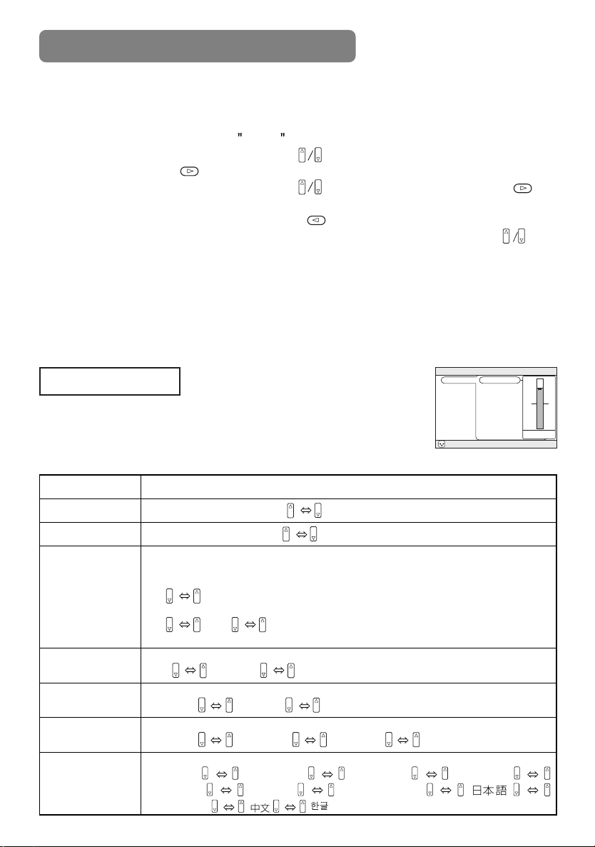
MAIN Menu
With the MAIN menu, the seven items shown in the Table below can be
performed.
Perform each operation in accordance with the instructions in the Table.
MAIN Menu
Item Description
BRIGHT
CONTRAST
ASPECT
PICT.POSIT.
GAMMA
MIRROR
LANGUAGE
2
Adjust Brightness: Light Dark
Adjust Contrast: Strong Weak
Select Aspect Ratio:
At RGB Input or Hi-Vision 1125i(1035i/1080i)/750p of COMPONENT VIDEO
Input:
4:3 16:9
At VIDEO Input, S-VIDEO Input or 525i/525p/625i of COMPONENT VIDEO Input:
4:3 16:9 SMALL
• The SMALL picture may not be displayed correctly with certain input signals.
Select Picture Position (for 16:9/SMALL Picture):
TOP CENTER BOTTOM
Select Gamma Mode:
NORMAL CINEMA DYNAMIC
Select Mirror Status:
NORMAL H:INVERT V:INVERT H&V:INVERT
Select Menu Language:
ENGLISH
ITALIANO
FRANÇAIS DEUTSCH ESPAÑOL
NORSK NEDERLANDS
POTUGUÊS
to select a menu name, then press the
to select an item, then press the or
: During operation, press the RESET button.
(Functions that are executed at the same time
as a selection, including H PHASE, LANGUAGE
selection, and ADJUST, will not be reset.)
MENU
MAIN
BRIGHT
PICTURE-1
CONTRAST
PICTURE-2
ASPECT
INPUT
PICT. POSIT.
AUTO
GAMMA
SCREEN
MIRROR
OPTION
LANGUAGE
WIRELESS
: SELECT
Example : MAIN Menu
(BRIGHT)
.
12
Page 3
PICTURE-1 Menu
MENU
: SELECT
MAIN
PICTURE-1
PICTURE-2
INPUT
AUTO
SCREEN
OPTION
WIRELESS
COLOR BAL R
COLOR BAL B
SHARPNESS
COLOR
TINT
12
MENU
: SELECT
MAIN
PICTURE-1
PICTURE-2
INPUT
AUTO
SCREEN
OPTION
WIRELESS
V POSITION
H POSITION
H PHASE
H SIZE
OVER SCAN
12
With the PICTURE-1 menu, the five items shown in the Table
below can be performed.
Perform each operation in accordance with the instructions in the
Table.
PICTURE-1 Menu
Item Description
Example : PICTURE1 Menu
(COLOR BAL R)
COLOR BAL R
COLOR BAL B
SHARPNESS
COLOR
TINT
Adjust Red Color Balance: Dark Light
Adjust Blue Color Balance: Dark Light
Adjust Sharpness (for VIDEO/S-VIDEO): Clear Soft
Adjust COLOR (for VIDEO/S-VIDEO/COMPONENT VIDEO):
Dark Light
Adjust Tint (for VIDEO/S-VIDEO): Green Red
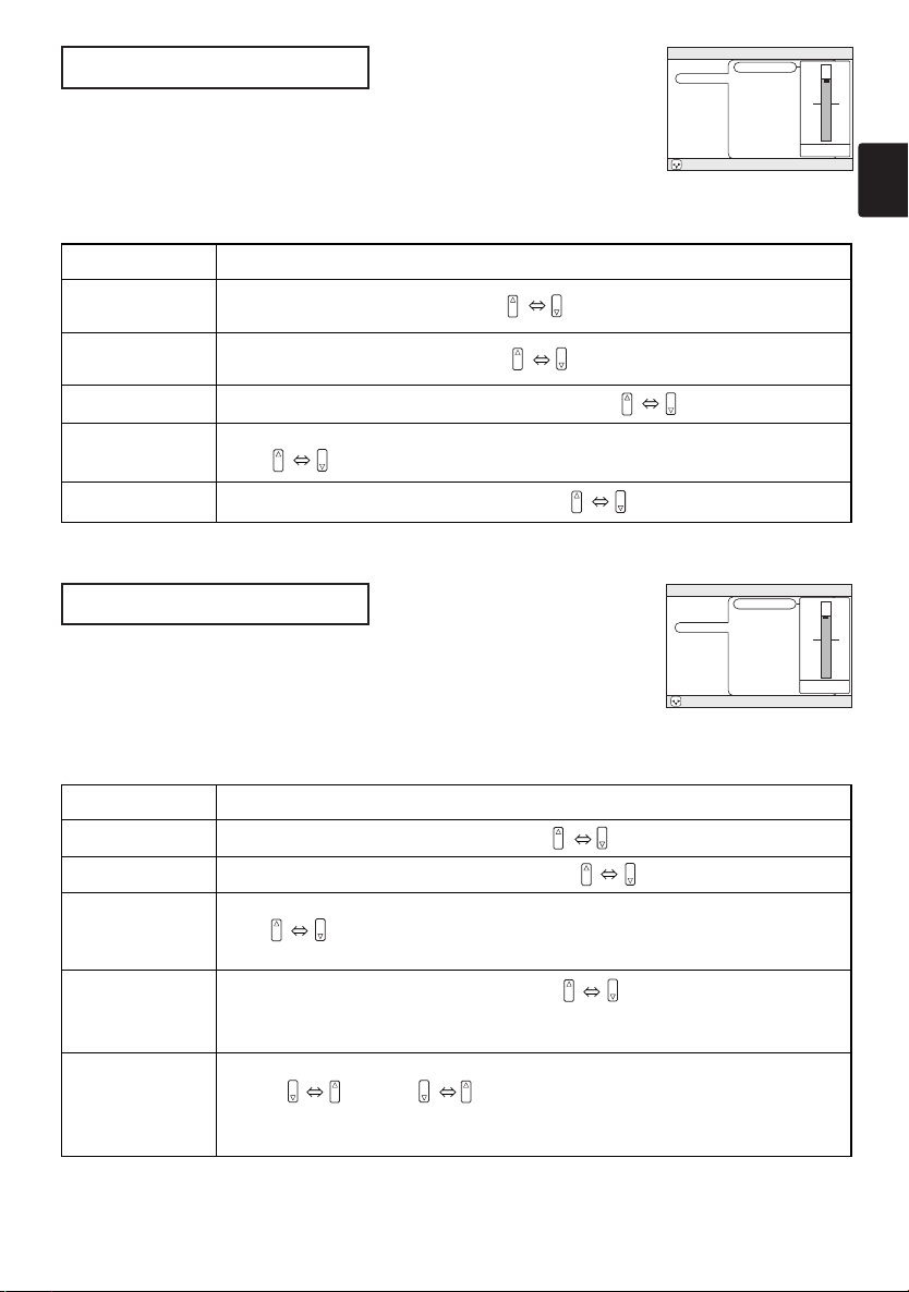
PICTURE-2 Menu
With the PICTURE-2 menu, the five items shown in the Table
below can be performed.
Perform each operation in accordance with the instructions in the
Table.
PICTURE-2 Menu
Item Description
V POSITION
H POSITION
H PHASE
Adjust Vertical Position (for RGB): Up Down
Adjust Horizontal Position (for RGB): Left Right
Adjust Horizontal Phase (for RGB/COMPONENT VIDEO):
Right Left
• Adjust to eliminate flicker.
Example : PICTURE2 Menu
(V POSITION)
H SIZE
OVER SCAN
Adjust Horizontal Size (for RGB): Large Small
• If the horizontal size adjustment is excessive, the image may not be displayed
correctly. In such a case, initialize H SIZE with the RESET button.
Select Over-scan Ratio (for VIDEO/S-VIDEO/COMPONENT VIDEO):
LARGE MIDDLE SMALL
• If you select LARGE, you may note streaking on the top and bottom of the
screen, or flicker. If this is irritating, we suggest you select SMALL.
3
Page 4
MULTIFUNCTIONAL SETTINGS (continued)
MENU
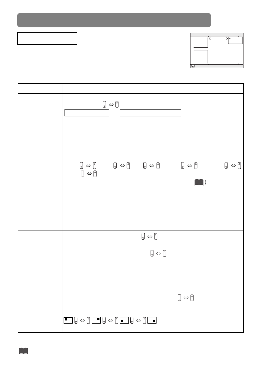
INPUT Menu
The three Input menu items listed in the table below can be manipulated. For
RGB input, the reception signal’s horizontal and vertical frequency is displayed
on the initial menu screen. Use the table below as a guide for operation.
INPUT Menu
Item Description
BNC Pin (R/CR/PR, G/Y, B/CB/PB, H, V) function selection:
BNC
VIDEO
BNC (RGB)
(R) (G) (B) (H) (V) (C
(Pins for RGB) (Pins for COMPONENT)
Selecting BNC (RGB) allows the 5 RGB2 pins (R/CR/PR, G/Y, B/CB/PB, H, V) to be
used as RGB signal BNC input as-is.
Selecting BNC (COMPONENT) allows the 3 leftmost RGB2 pins (R/CR/PR, G/Y,
B/CB/PB) to be used as the COMPONENT VIDEO input CR/PR, Y, and CB/PBpins.
Select Mode of Signal Type (for VIDEO/S-VIDEO):
AUTO NTSC PAL SECAM NTSC4.43
M-PAL N-PAL
When AUTO is selected, the video/ S-video input function under ADJUST ( are enabled, and is
executed simultaneously so that the optimum signal mode is selected from among the modes listed above.
Use this function if the image becomes unstable with VIDEO/S-VIDEO. (e.g. The image becomes irregular, or lacks color.)
•
AUTO mode may not function correctly with a PAL60 signal and certain other signals.
• The AUTO mode operation requires approximately 10 seconds.
• For COMPONENT VIDEO, the signal type is identified automatically even if
this function is inactive. For a HDTV signal, refer to the item HDTV below.
BNC (COMPONENT)
) (Y) (CB/PB) ( - ) ( - )
R/PR
MAIN
PICTURE-1
PICTURE-2
INPUT
AUTO
SCREEN
OPTION
WIRELESS
: SELECT
Example : INPUT Menu
5
BNC
VIDEO
HDTV
SYNC ON G
P. IN P. INPUT
P. IN P. POSIT
(BNC)
RGB
COMPONENT
HDTV
Select HDTV Signal Mode: 1080i 1035i
•
If the selected HDTV mode is incompatible with the input signal, the picture may be distorted.
On/Off SYNC ON G Mode: TURN ON TURN OFF
Selecting TURN ON turns on the SYNC ON G mode. The SYNC ON G mode
SYNC ON G
allows reception of SYNC on G.
• In the SYNC ON G mode, the picture may be distorted with certain input
signals. In such a case, remove the signal connector so that no signal is
received and turn SYNC ON G off, and then reconnect the signal.
P. IN P. INPUT
P. IN P. screen (*) input signal selection: VIDEO S-VIDEO
Selects the signal displayed on the P. IN P. subscreen.
P. IN P. screen (*) display position selection:
P. IN P. POSIT
Selects the position at which the P. IN P. subscreen is displayed.
(*) The P. IN P. (picture-in-picture) function displays the video signal image in a subscreen (P. IN P. screen) on
top of the screen on which the RGB signal image is being displayed. (See “Displaying Child Window” Vol.1
.)
24
4
Page 5

AUTO Menu
With the AUTO menu, the four items shown in the Table below can
be performed.
Please perform each operation in accordance with the instructions
in the Table.
AUTO Menu
Item Description
Auto Adjust (for RGB): Automatically adjusts H POSITION, V POSITION, H
PHASE, and H SIZE. Use this function with the maximum window size.
Auto Adjust (for VIDEO/S-VIDEO): This function automatically selects the
appropriate signal mode depending on input signals. This is only performed if
ADJUST
KEYSTONE
POWER OFF
AUTO is selected on the VIDEO menu item ( ) of the INPUT menu.
• This function may not be available with a PAL60 signal and certain other
signals.
• The AUTO mode operation requires approximately 10 seconds.
•
For COMPONENT VIDEO, the signal type is identified automatically even if this
function is inactive. For more information on HDTV signals, see HDTV. ( )
Automatic keystone distortion correction:
You can automatically correct vertical keystone distortion corresponding to the
angle (forward/backward tilt) at which the unit is set up.
• If the projection screen is inclined, or if the projector is angled downwards, it
may not be possible to make the correct adjustment when V: INVERT or H&V:
INVERT is selected under the MIRROR item of the MAIN menu.
• When the zoom adjustment is set to the TELE side, automatic correction may
be excessive. The automatic correction function should be used with zoom
set to WIDE whenever possible.
Adjust POWER OFF Time:
Long (MAX. 99 min.) Short (Min. 1 min.) (DISABLE: 0 min.)
If the time set here passes without valid signal input (there is no signal input, or
signal input is out of specifications), the standby mode is set (see "TURNING
ON THE POWER" Vol.1 ). This function is inactive when DISABLE (0 min.) is
15
selected.
4
MENU
MAIN
PICTURE-1
PICTURE-2
INPUT
AUTO
SCREEN
OPTION
WIRELESS
: SELECT
ADJUST
KEYSTONE
POWER OFF
ONE TOUCH
EXECUTE
Example : AUTO Menu
(ADJUST)
4
ONE TOUCH
Enabling/disabling the KEYSTONE function using the ONE TOUCH
button:
TURN ON
TURN OFF
Pressing the ONE TOUCH button will automatically retrieve pictures and
automatically adjust the screen (see “ADJUSTING SCREEN WITH ONETOUCH”
Vol.1
), and you can also set the function to execute KEYSTONE
23
(see above in this table) simultaneously when pressed. KEYSTONE will be
executed if TURN ON is selected.
5
Page 6

MULTIFUNCTIONAL SETTINGS (continued)
MENU
MAIN
SCREEN Menu
With the SCREEN menu, the five items shown in the Table below can be performed.
Please perform each operation in accordance with the instructions in the Table.
SCREEN Menu
Item Description
BLANK
START UP
MyScreen
MyScreen Size
MyScreen Lock
6
Selection of BLANK Screen:
MyScreen ORIGINAL
.. . .
The BLANK Screen may be voluntarily selected. The BLANK Screen is displayed when the screen
has been erased (i.e., made to vanish) by manipulating the BLANK button (please refer to the
“Temporarily Blanking the Screen” section of the separate booklet, Vol. 1 (Basic)).
MyScreen:
Using the MyScreen category (see this Table, below), one can register a desired screen
(or screens). At the time of factory shipment, this is set as a non-patterned (plain) blue color screen.
ORIGINAL:
Option screens:
•
The MyScreen and the ORIGINAL Screen will each change to a non-patterned (plain) black color
Existing standard screens. Please make confirmation using the actual screen(s).
Various colored non-patterned (plain) screens displayed within the Menus.
screen several minutes after being displayed.
Selection of START UP Screen:
MyScreen ORIGINAL
The START UP Screen may be voluntarily selected. The START UP Screen is displayed when
no signal has been inputted, or when spec signals are being inputted.
MyScreen:
Using the MyScreen category (see this Table, below), one can register a desired screen
(or screens). At the time of factory shipment, this is set as a non-patterned (plain) blue color screen.
ORIGINAL:
TURN OFF:
•
The MyScreen and ORIGINAL screens will switch to the BLANK screen (see above in this
Existing standard screens. Please make confirmation using the actual screen(s).
A non-patterned (plain) blue color screen.
table) a few minutes after being displayed. If the BLANK screen is the MyScreen or
ORIGINAL screen, it will turn immediately to a solid black screen.
Registration of MyScreen:
When this item is executed, the MyScreen Menu for registration of MyScreen for the BLANK Screen
and the START UP Screen is displayed. When operations are performed in accordance with this Menu,
one can “cut” and register desired screens from among the received images within the display.
1.
After the “Do you start capturing this picture?” message has been displayed, pressing the ESC (or
RESET) button interrupts execution of the MyScreen. When the ENTER button is pressed, the picture
becomes static (no longer moves), and a frame for picture cutting, as well as the message that follows
below, appear. Please press the button when the screen you want to register is currently being displayed.
2.
When the “Move the capture area as you want.” message has been displayed, pressing the ESC (or RESET)
button will eliminate the static state of the picture, and operations can be performed again from operation 1.
The frame can be moved using the buttons. After designating the screen you
want to register, pressing the ENTER button will initiate screen registration. The registration
process takes approximately 1 minute to complete.
3. When the registration has been completed, the screen of the registered MyScreen, plus the
message, “MyScreen registration is finished,” will be displayed for several seconds, after which
the operation is terminated.
Selection of MyScreen display size:
x1 FULL
Invalidation of MyScreen registration function:
When TURN ON is selected, the MyScreen category (see this Table, above) cannot be executed; in
this way, one can prohibit rewrites (“writeovers”) of the MyScreen.
Example : SCREEN Menu
..
TURN ON TURN OFF
PICTURE-1
PICTURE-2
INPUT
AUTO
SCREEN
OPTION
WIRELESS
: SELECT
BLANK
START UP
MyScreen
MyScreen Size
MyScreen Lock
(BLANK)
TURN OFF
MyScreen
ORIGINAL
Page 7

OPTION Menu
MENU
: SELECT
MAIN
PICTURE-1
PICTURE-2
INPUT
AUTO
SCREEN
OPTION
WIRELESS
VOLUME
WHISPER
IR REMOTE
LAMP TIME
FILTER TIME
12
With the OPTION menu, the five items shown in the Table below can
be performed.
Please perform each operation in accordance with the instructions in
the Table.
OPTION Menu
Item Description
VOLUME
WHISPER
IR REMOTE
LAMP TIME
FILTER TIME
Adjust Volume: High Low
Select WHISPER Mode:
NORMAL WHISPER
When WHISPER is selected the WHISPER mode is activated. In the WHISPER
mode, acoustic noise and screen brightness are reduced.
Selecting the remote control receiver:
The unit has 3 remote control receivers, as shown in the figure
to the right (1, 2, and 3). You can select which of them to
activate (“v” in the figure), and which to disable.
• The ambient lighting and other factors may prevent the
remote control operation from functioning properly. If this
happens, use this function to disable receivers being
impacted by unneeded light.
Refer to LAMP TIME: When set, this function displays the total time the
projector lamp has been used since new.
Reset LAMP TIME [Use this function only when the lamp has been replaced!]:
Depress the RESET button for at least 3 seconds while lamp time is being
displayed. The reset menu will then appear. After you replace the lamp with a
new lamp, select RESET on the menu with the button.
• Do not reset the lamp time unless you have replaced the lamp. And, always
reset the lamp time when replacing the lamp. The message functions will not
operate properly if the lamp time is not reset correctly.
•
Before replacing the lamp, carefully read the descriptions headed "THE LAMP".
Refer to FILTER TIME: This function displays the total time the air-filter has
been used since new.
Reset FILTER TIME [Use this function only when the filter is cleaned or replaced!]:
Depress the RESET button for at least 3 seconds while lamp time is being
displayed. The reset menu will then appear. After you replace the filter, select
RESET on the menu with the button.
RESET CANCEL
• Do not reset the filter time unless you have cleaned or replaced the filter. And,
always reset the filter time when cleaning or replacing the filter. The message
functions will not operate properly if the filter time is not reset correctly.
•
Before cleaning or replacing the filter, carefully read the descriptions headed "THE AIR FILTER".
Example : OPTION Menu
(VOLUME)
2
3
3
112
12 3
12 3
12 3
12 3
12 3
12 3
WIRELESS Menu
The WIRELESS menu is only enabled if the wireless function is enabled. Using the
wireless function requires a Wireless & Network Module Terminal (sold separately). See
the Wireless & Network Module Terminal user’s manual for more information about the
WIRELESS menu. Contact your local dealer for more information about the wireless
function and Wireless & Network Module Terminal.
7
Page 8

WHAT TO DO WHEN YOU THINK A MACHINE DEFECT HAS OCCURRED
Related Messages
When the unit's power is ON, messages such as those shown below may be displayed. When
any such message is displayed on the screen, please respond as described below.
Message Description
CHANGE THE LAMP
AFTER REPLACING LAMP,
RESET THE LAMP TIMER.
CHANGE THE LAMP
AFTER REPLACING LAMP,
RESET THE LAMP TIMER.
THE POWER WILL TURN OFF
AFTER
CHANGE THE LAMP
AFTER REPLACING LAMP,
RESET THE LAMP TIMER.
THE POWER WILL TURN OFF
AFTER CLEANING AIR FILTER,
ON
AFTER 0 hr.
CLEAN THE AIR FILTER
RESET THE FILTER TIMER.
NO INPUT IS DETECTED
ON
SYNC IS OUT OF RANGE
fH
CHECK THE AIR FLOW
kHz Hz
(Note 1)
hr.
(Note 1)
fV
Lamp usage time is approaching 2,000 hours. (Note 2)
Preparation of a new lamp, and an early lamp change, is
recommended. After you have changed the lamp, please be
sure to reset the lamp timer.
Lamp usage time is approaching 2,000 hours. A lamp change
within hours is recommended. (Note 2)
When lamp usage reaches 2,000 hours, the power will
automatically be turned OFF. Please change the lamp by
referring to “THE LAMP” (Vol.1 ). After you have
changed the lamp, please be sure to reset the lamp
timer.
As lamp use has reached 2,000 hours, the power will soon be
automatically turned OFF. (Note 2)
Please immediately turn the power OFF, and follow the
instructions in the “THE LAMP” (Vol.1 ).
After you have changed the lamp, please be sure to reset the
lamp timer. ( )
A note of precaution when cleaning the air filter.
After cleaning the filter, operate FILTER TIME of the OPTION
Menu ( ), and perform reset of the filter timer.
There is no input signal.
Please confirm the signal input connection, and the status of the
signal source.
The horizontal or vertical wavelength of the inputted signal is
outside of the response parameters of this unit. Please confirm
the specs for this unit or the signal source specs.
The internal portion temperature is rising. Please turn the power
OFF, and allow the unit to cool down for approximately 20
minutes. After having confirmed the following items, then please
resent the power to ON.
•
Is there blockage of the air passage aperture?
•
Is the air filter dirty?
•
Does the peripheral temperature exceed 35°C?
7
7
27
27
NOTES
Note 1: Although this message will be automatically disappeared after around 3 minutes, it will be
reappeared every time the power is turned ON.
Note 2: Lamps have a finite product life. Lamps are characterized by the fact that, after long hours of
usage, a lamp will no longer light up, or the lamp will break or burst, etc. This unit is equipped
with an automatic shut-down function, such that the power will automatically be turned OFF
when lamp usage time has reached 2,000 hours. Please be aware, however, that among lamp
types, there are major differences in product lifetimes; a lamp may thus fail to light even prior
to the functioning of the automatic shut-down function of this unit.
8
Page 9

Regarding the Indicator Lamps
Lighting and flashing of the POWER indicator, the LAMP indicator, and the
TEMP indicator have the meanings as described in the Table below.
Please respond in accordance with the instructions within the Table.
POWER
indicator
The orange
lamp is lighted
Flashing of the green lamp
The green lamp is lighted
Flashing of the orange lamp
Blinking of the
red lamp
The red lamp
is lighted, or
blinks
The red lamp
is lighted, or
blinks
The red lamp
is lighted, or
blinks
The red lamp is
lighted, or
blinks
The green lamp
is lighted
The green
lamp is lighted
LAMP
indicator
Turned OFF
(Not lighted)
Turned OFF Turned OFF
Turned OFF Turned OFF
Turned OFF Turned OFF
- -
The red lamp
is lighted
Blinking of the
red lamp
Turned
OFF
Turned
OFF
Alternative blinking
with the red lamp
Simultaneous blinking
with the red lamp
TEMP
indicator
Turned OFF
(Not lighted)
Turned
OFF
Turned
OFF
Blinking of the
red lamp
The red lamp is
lighted
Description
The STANDBY mode is set
The unit is warming up. Please wait.
The unit is in an ON state. Ordinary operations may be performed.
The unit is cooling down. Please wait.
The unit is cooling down. Please wait.
A certain error has been detected. Wait until the POWER indicator lamp has finished
flashing, and then perform the proper response measure using the item descriptions
below as reference.
The lamp does not light.
There is a possibility that the interior portion has become heated. Turn the power OFF and wait
approximately 20 minutes. After the main unit has cooled down, please confirm whether or not
there is blockage of the air passage aperture, whether or not the filter is dirty, and/or whether or
not the peripheral temperature exceeds 35°C, etc. After performing any needed maintenance,
turn the power ON again; if the same display is displayed, then please change the lamp.
Either there is no lamp and/or lamp cover, or either of these has not been properly fixed
(attached). Turn the power OFF and wait approximately 45 minutes. After the main unit has
sufficiently cooled down, please make confirmation of the attachment state of the lamp and
lamp cover. After performing any needed maintenance, turn the power ON again; if the same
display is displayed, then please contact a sales store or a service company.
The cooling fan is not operating. Turn the power OFF and wait approximately 20 minutes. After the
main unit has cooled down, please make confirmation that no foreign matter has become caught in
the fan, etc. After performing any needed maintenance, turn the power ON again; if the same display
is displayed, then please contact a sales store or a service company.
There is a possibility that the interior portion has become heated. Turn the power OFF and wait
approximately 20 minutes. After the main unit has cooled down, please confirm whether or not
there is blockage of the air passage aperture, whether or not the filter is dirty, and/or whether or
not the peripheral temperature exceeds 35°C, etc. After performing any needed maintenance,
turn the power ON again; if the same display is displayed, then please contact a sales store or a
service company.
There is a possibility that the interior portion has become overcooled. Please use the unit within
the usage temperature parameters (0°C to 35°C). After performing any needed maintenance,
turn the power ON again; if the same display is displayed, then please contact a sales store or a
service company.
This is a notification that it is time to clean the filter.
After cleaning the filter, operate the FILTER TIME portion of the OPTION Menu, and perform
reset of the FILTER TIME.
NOTE
When the interior portion has become overheated, for safety purposes, the power source is automatically turned OFF,
and the indicator lamps may also be turned OFF. Press the “
for approximately 20 minutes. Please then use the unit only after having first confirmed that the unit has sufficiently
cooled down.
” (power OFF) side of the main power switch, and wait
9
9
Page 10

WHAT TO DO WHEN YOU THINK A MACHINE DEFECT HAS OCCURRED (continued)
Phenomena That May Easily Be Mistaken for Machine Defects
Before requesting repair, check in accordance with the following chart.
If the situation cannot be corrected, then contact your dealer.
Phenomenon
Power does not
come ON
No sound or
pictures are
outputted
Pictures are
displayed, but no
sounds are heard
Sounds are
heard, but no
pictures are
displayed
Cases not involving a machine defect
The main power source is not ON.
The electrical power cord is not plugged in. Correctly connect the power cord.
The main power source has been
interrupted during operation, such as by
a power outage (blackout), etc.
The input changeover settings
are mismatched.
No signal is being inputted.
The electrical wiring to this unit
is not correctly connected.
The volume setting has been set at (or
adjusted to) an extremely low level.
The MUTE mode is the current setting.
The electrical wiring to this unit
is not correctly connected.
The brightness setting has been set at
(or adjusted to) an extremely low level.
The lens cap has not been removed.
Items to be confirmed
Turn on the main power.
Be sure to press the “O” (power OFF) side
of the main power switch, and leave this OFF
for approximately 20 minutes. After the unit
has sufficiently cooled down, turn ON the
power source.
Select the input signal, and
correct the settings.
Correctly connect the connection cord.
Correctly connect the connection cord.
Adjust the VOLUME setting to a higher level.
Press the MUTE button to release
(change) the MUTE mode setting.
Correctly connect the connection cord.
Adjust the BRIGHT setting to a
brighter level.
Remove the lens cap.
Reference
Page(s)
Vol.1-3, 15
Vol.1-15
Vol.1-16
Vol.1-8-12
Vol.1-8-12
Vol.1-18
Vol.1-18
Vol.1-8-12
Vol.2-2
Vol.1-15
Colors have a fadedout appearance
Color tone is poor
Pictures appear
dark
Pictures appear
blurry
Input signal changes
with no-operation.
INPUT dial is set between the click
points.
Color depth setting or color tone setting
The brightness setting and/or contrast
setting has not been properly adjusted.
The WHISPER mode is the current
setting.
Lamp is approaching the end of its
product lifetime.
Either the FOCUS setting or the H
PHASE is not properly adjusted.
Perform picture adjustments by changing the
COLOR BAL R, the COLOR BAL B, and/or the
TINT settings, etc.
Perform picture adjustments by changing the
BRIGHT and/or CONTRAST settings, etc.
Change (by releasing) from the
WHISPER mode.
Exchange the old lamp with a new
lamp.
Adjust the FOCUS and H PHASE settings.
Turn the INPUT dial and set it at the
click point.
Vol.2-3
Vol.2-2
Vol.2-7
Vol.1-27, 28
Vol.1-16
Vol.2-3
Vol.1-16
NOTE
Although bright spots or dark spots may appear on the screen, this is a unique characteristic of liquid crystal displays, and
such do not constitute or imply a machine defect.
10
Page 11

380
117
130
10 303
290
120
28
72
SPECIFICATIONS
NOTE
• This specifications are subject to change without notice.
Item Specification
Product name Liquid crystal projector
Liquid
crystal
panel
Lens Zoom lens F=1.7 ~ 2.4 f=30.5 ~ 45.8 mm
Lamp 275 W UHB
Speaker 1.0W+1.0W (Stereo)
Power supply AC100 ~ 120V, 4.7A / AC220 ~ 240V, 2.0A
Power consumption 430W
Temperature range 0 ~ 35°C (Operating)
Size 380 (W) x 120 (H) x 290 (D) mm (Not including protruding parts)
Weight (mass) 5.7 kg
Ports
Optional Parts
Panel size 2.5 cm (0.99 type)
Drive system TFT active matrix
Pixels 786,432 pixels (1024 horizontal x 768 vertical)
RGB Input Ports
RGB ................................1
BNC (when RGB selected)
– (R.G.B.H.V) ..................1
DVI..................................1
VIDEO Input Ports
VIDEO IN ........................1
S-VIDEO IN ....................1
COMPONENT VIDEO
– (C
R/PR, CB/PB, Y) ........1
BNC
(when COMPONENT selected)
– (CR/PR, Y, CB/PB) ........1
AUDIO Ports
AUDIO IN 1 ....................1
AUDIO IN 2 ....................1
AUDIO IN (R, L)..............1
RGB Output Port
RGB OUT........................1
AUDIO Output Port
AUDIO OUT....................1
CONTROL Ports
CONTROL ......................1
USB ................................1
Other Ports
WIRELESS & NETWORK MODULE
REMOTE CONTROL ......1
Lamp: DT00531 Air Filter: NJ07081
* For others, consult your dealer.
....1
Dimension Diagram
Unit : mm
11
Page 12

WARRANTY AND AFTER-SERVICE
If a problem occurs with the equipment, first refer to the “WHAT TO DO WHEN YOU
THINK A MACHINE DEFECT HAS OCCURRED” section and run through the suggested
checks. If this does not resolve the problem contact your dealer or service company. They
will tell you what warranty condition is applied.
8
12
 Loading...