

Page 1
HITACHI
COLOUR MONITOR
CM811 ET
CM812ET
BEDIENUNGSANLEITUNG...19
USER MANUAL ..... I
MANUAL DE USUARIO...33
CM813ET
CM814ET
with EasyMen u !
EasyMenu IS HITACHI’S On Screen Display function for easy operat[on
Oceooo 00 00 0.0
MANUEL UTILISATEUR...(3I
MANUALE D’USO...47
/
\
READ THE INSTRUCTIONS INSIDE CAREFULLY.
KEEP THIS USER MANUAL FOR FUTURE REFERENCE.
For future reference, record the serial number of your colour monitor.
SERIAL No.
The serial number is located on the rear of the monitor.
This monitor is
equipped with VESA DPMS.
ENERGYSTARoemblem does not represent EPA endorsement
The
of any product or service.
ENERGYSTAR@Partner, Hitachi,Ltd. has determined that this
As an
product meets the
ENERGYSTAR@compliant when used with a computer
ENERGYSTARoguidelines for energy efficiency.
Q*
~
%L
~+
100%
%0
4.
l-!
&“
@
+.
liaa~~
Page 2
NOTE:
~
The information in this manual is subject to change without notice. The manufacturer assumes no
responsibility for any errors that may appear in this manual.
TRADEMARK ACKNOWLEDGEMENT
VGA is a registered trademark of International Business Machines Corporation.
Apple and Macintosh are registered trademark of Apple Computer, Inc.
VESA is a trademark of a nonprofit organization, Video Electronics Standard Association.
ENERGYSTAR@isa trademark of Environmental Protection Agency (EPA),
HINWEIS:
Anderungen der Datenin dieser Bedienungsanleitung sindvorbehalten, Der Hersteller ubernimmt
keine Haftung fur jegliche in diesem Handbuch eventuell enthaltenen Irrtumer.
GESCHUTZTE WARENZEICHEN
VGA ist ein eingetragenes Warenzeichen der International Business Machines Corporation.
Apple und Macintosh ist eingetragenes Warenzeichen der Apple Computer, Inc.
VESA ist ein Warenzeichen der Video Electronics Standard Association, einer Organisation ohne
Erwerbscharakter.
ENERGYSTAR@istein Warenzeichen der Environmental Protection Agency (EPA).
NOTA:
La informaci6n contenida en este manual est~ sujeta a cambios sin previo aviso. El fabricate no
se responsabiliza de Ios errores que puedan aparecer en este manual.
RECONOCIMIENTO DE MARCAS
VGA es una marca registrada de International Business Machines Corporation.
Apple y Macintosh son marca registradas de Apple Computer, Inc.
VESA es una mares registrada de una organizaci6n sin fmimo de Iucro, Video Electronics Standard
Association,
ENERGYSTAR@esuna marca de Environmental Protection Agency (EPA).
.
NOTA:
Tutte Ie informazioni di questo manuale sono soggette ad essere modificate senza preawiso. II
costruttore non si assume responsabilita’ per errori che possono essere riportati SUImanuale.
Marchi di fabbrica riconosciuti.
VGA e’ urn marchio di fabbrica regisrato da International Business Machine Corporation.
Apple e Macintosh sono marchi di fabbrica regisrato da Apple Computer, Inc.
VESA e’ il marchio di riconoscimento dells organizzazione a non-profitto, Video Electronics
Standard Association.
ENERGYSTAR@e’ilmarchio di fabbrica dells Eviromental Protection Agency (EPA).
REMARQUE:
Les inforrnations contenues clans ce manuel peuvent &re modifi6es saris pr6avis. Le constructeur
n’accepte aucune responsabilit~ pour Ies erreurs qui peuvent &entuellement apparaitre clans ce
manuel.
MARQUES DEPOSEES
VGA est une marque d.4pos6e d’ International Business Machines Corporation.
Apple et Macintosh sent des marques d6pos6e d’ Apple Computer, Inc.
VESA est la marque d’une organisation saris but Iucratif, la Video Electronics Standard Association.
ENERGYSTAR@est une marque de 1’EPA (Environmental Protection Agency, USA).
Page 3
FWTURES...... ....................................................................................................I
~~-..7.,.
,$$-
E
8=
E
17
18
CAUTIONS......... .................................................................................................2 ‘
INSTALLATION........
STANDARD
●
Operation ...................................................................................................... II
POWER SAVING SYSTEM ............................................................................... 17
PLUG & PLAY ............
SPECIFICATIONS
The following features are provided by the Colour Monitor.
Sharpest Focus and Highest Contrast
Flat screen CRT with anti-glare, dynamic focus circuit, dark glass, and an INVAR shadow mask
gives the sharpest focus and highest contrast to minimize eye fatigue.
Wide-range Multi-Scanning
Automatic scanning and automatic adjustment to conform with a wide range of scanning frequencies
and user requirements.
Digital Picture Control Function
Position, size, rotation, pincushion, trapezoid, right pincushion and right trapezoid are adjustable by
digital controls.
Geometry setting can be stored for different H/V frequencies.
functions can store 26 sets of geometry settings including the standard factory settings.
Digital Colour Control Function
Red, green, and blue colour balance is adjustable by digital control.
An adjusted colour setting can be stored and recalled by the colour select button.
Power Saving System
The Environmental Protection Agency (EPA) has established a voluntary program by which
manufacturers enable computer products to go into low power states while not being used. This
monitor has a low power “sleep” mode, which is compliant with the EPA requirements for the
STAR@’program, and will assist you in conserving energy.
Please refer to the section of “POWER SAVING SYSTEM” for details.
EasyMenu
An On Screen Display ti,mction that allows direct access to adjust all operations from the front
switches.
Moire Reduction
This monitor has horizontal and vertical moire reduction fundlon.
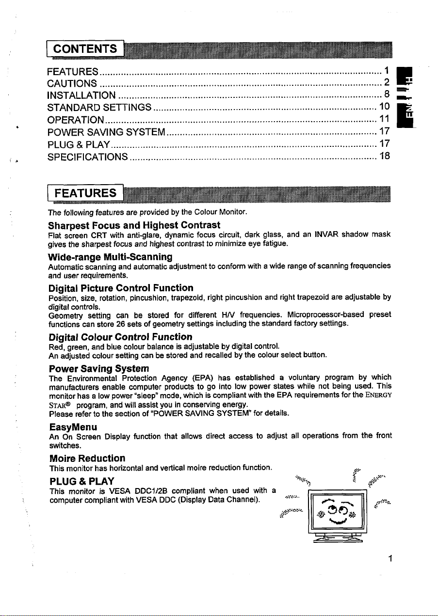
PLUG & PLAY
This monitor is VESA DDC1/2B compliant when used with a
computer compliant with VESA DDC (Display Data Channel). ‘-;”<;-’”
SE~lNGS .................................................................................... 10 :
..... ......................................................................................
........................................................................................
.............................................................................................
Microprocessor-based preset
ENERGY
..$/
.,>,.,
..-,,
~ity;~”.<.
.,.
,*r&5-* “’’”-
$
>
..
m
1
Page 4
■ NEVER REMOVE THE REAR COVER!
The rear cover MUST be removed only by authorized service personnel. This colour monitor
—
~ contains highvoltage components.
■ THE RECEPTACLE SHOULD BE CLOSE TO THE MONITOR AND EASILY
=
—
ACCESSIBLE !
9 iNSTALL THE UNIT IN AN SUITABLE ENVIRONMENT !
DO NOT expose this monitor to rain or moisture to prevent electric shock or fire hazard. This unit
is designed to be used in an office or business environment.
DO NOT subject the unit to vibrations, dust, or corrosive gases.
■ KEEP IN A WELL VENTILATED PLACE !
DO NOT cover this monitor or place anything against any sides (not only the top, right and left side
but also the rear and bottom side) of unit. Ventilation holes are provided at all sides of the rear
cover to prevent the temperature from rising.
■ KEEP AWAY FROM HEAT SOURCES !
AVOID placing the unit in direct sunshine or near a heating appliance.
■ BE CAREFUL OF MAGNETIC FIELDS !
DO NOT place a magnet, loudspeaker system, floppy disk drive, printer, or anything which will
generate magnetism near the unit. A magnetic field may cause blurred colours or distortion of the
displayed pattern.
■ BE CAREFUL OF GENERATED MAGNETISM !
After the power has been turned on or “DEGAUSS” button has been pressed, the CRT is
demagnetized for approximately 10 seconds. This generates a strong magnetic field around the
front cover which may affect the data stored on magnetic tape or disks near the front cover. Place
such magnetic recording equipment and tapes/disks away from this unit.
■ AMBlENT ILLUMINATION
Avoid direct rays of the sun or room lighting onto the CRT screen in order to prevent eye fatigue.
■ THE ENCLOSED POWER CORD MUST BE USED !
In Europe, a proper European standard approved power cord is to be used with this monitor, For a
rated current up to 6A, a type not lighter than H05W-F 3G 0.75 mmz or H05WH2-F 3G 0.75 mmz
must be used.
In USA/Canada, use a UL LISTED/CSA L4BELLED or CERTIFIED power cord set meeting the
following specifications
Rating: min. 125V, 7A
Length: max. 3.Om
Type: SVT or SJT
Plug type: NEMA 5-15P figure, Parallel blade, Grounding type
Failure to do so may cause fire or electric shock hazard.
■ USE ONLY THE CORRECT VOLTAGE POWER OUTLET WITH SAFETY
GROUND CONNECTION !
100-120 V for USA, Canada, etc.
200-240 V for Europe, etc.
(This monitor will automatically adjust to the input voltage 100- 120/ 200- 240V.)
2
Page 5
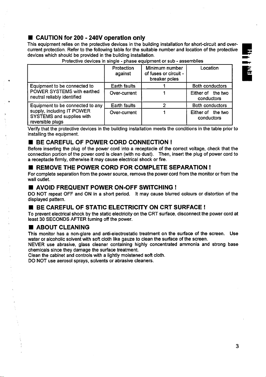
■ CAUTION for 200- 240V operation only
This equipment relies on the protective devices in the building installation for short-circuit and over-
current protection. Refer to the following table for the suitable number and location of the protective .
devices which should be provided in the building installation.
4
Equipment to be connected to Earth faults
POWER SYSTEMS with earthed
h
neutral reliably identified
Equipment to be connected to any Earth faults
supply, including IT POWER
SYSTEMS and supplies with
reversible plugs
Verify that the protective devices in the building installation meets the conditions in the table prior to
installing the equipment.
Protective devices in single - phase equipment or sub - assemblies
Protection
against
Over-current
Over-current
Minimum number
of fuses or circuit -
breaker poles
1 Both conductors
1
2 Both mnductors
1
Either of the two
Either of the two
Location
conductors
conductors
E
w
E
■ BE CAREFUL OF POWER CORD CONNECTION !
Before inserting the plug of the power cord into a receptacle of the correct voltage, check that the
connection portion of the power cord is clean (with no dust). Then, insert the plug of power cord to
a receptacle firmly, otherwise it may cause electrical shock or fire.
■ REMOVE THE POWER CORD FOR COMPLETE SEPARATION!
For complete separation from the power source, remove the power cord from the monitor or from the
wall outlet.
■ AVOID FREQUENT POWER ON-OFF SWITCHING !
DO NOT repeat OFF and ON in a short period. It may cause blurred colours or distortion of the
displayed pattern.
■ BE CAREFUL OF STATIC ELECTRICIN ON CRT SURFACE !
To prevent electrical shock by the static electricity on the CRT surface, disconnect the power cord at
least 30 SECONDS AFTER turning off the power.
■ ABOUT CLEANING
This monitor has a non-glare and anti-electrostatic treatment on the surface of the screen. Use
water or alcoholic solvent with soft cloth like gauze to clean the surface of the screen.
NEVER use abrasive, glass cleaner containing highly concentrated ammonia and strong base
chemicals since they damage the surface treatment.
Clean the cabinet and controls with a lightly moistened soft cloth.
DO NOT use aerosol sprays, solvents or abrasive cleaners.
3
Page 6
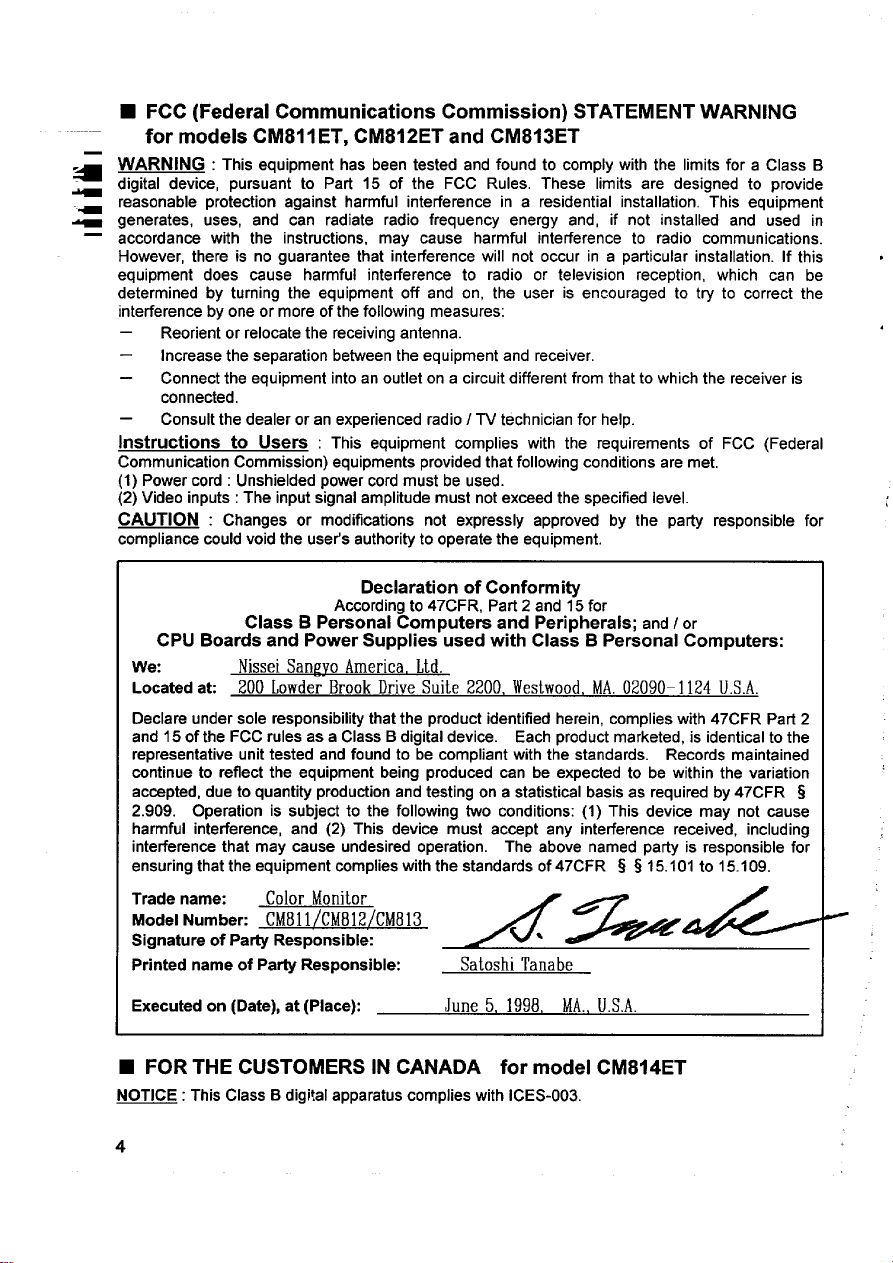
■ FCC (Federal Communications Commission) STATEMENT WARNING
for models CM811 ET, CM812ET and CM813ET
WARNING :
digital device, pursuant to Part 15 of the FCC Rules. These limits are designed to provide
reasonable protection against harmful interference in a residential installation. This equipment
generates, uses, and can radiate radio frequency energy and, if not installed and used in
accordance with the instructions, may cause harmful interference to radio communications.
However, there is no guarantee that interference will not occur in a particular installation. If this
equipment does cause harmful interference to radio or television reception, which can be
determined by turning the equipment off and on, the user is encouraged to try to correct the
interference by one or more of the following measures:
—
Reorient or relocate the receiving antenna.
—
Increase the separation between the equipment and receiver.
—
Connect the equipment intoan outlet on a circuit different from that to which the receiver is
connected.
—
Consult the dealer or an experienced radio/TV technician for help.
ltIStrUCtiOtIS to USerS : This equipment complies with the requirements of FCC (Federal
Communication Commission) equipments provided that following conditions are met,
(1) Power cord : Unshielded power cord must be used.
(2) Video inputs : The input signal amplitude must not exceed the specified level.
CAUTION : Changes or modifications not expressly approved by the party responsible for
compliance could void the uset’s authority to operate the equipment.
CPU Boards and Power Supplies used with Class B Personal Computers:
We:
Located ak 200 Lewder Brook Drive Suite 2200, Westwood,MA,02090-1124 U.S.A.
Declare under sole responsibility that the product identified herein, complies with 47CFR Part 2
and 15 of the FCC rules as a Class B digital device. Each product marketed, is identical to the
representative unit tested and found to be compliant with the standards. Records maintained
continue to reflect the equipment being produced can be expected to be within the variation
accepted, due to quantity production and testing on a statistical basis as required by 47CFR 3
2.909. Operation is subject to the following two conditions: (1) This device may not cause
harmful interference, and (2) This device must accept any interference received, including
interference that may cause undesired operation. The above named party is responsible for
ensuring that the equipment complies with the standards of 47CFR s 315.101 to 15.109.
Trade name:
Model Numbec CM81l/CM812/CM813
Signature of Party Responsible:
Printed name of Party Responsible:
This equipment has been tested and found to comply with the limits for a Class B
Declaration of Conformity
According to 47CFR, Part 2 and 15 for
Class B Personal Computers and Peripherals; and/or
Nissei Sanevo America, Ltd.
Color Monitor
/*&
Satoshi Tanabe
Executed on (Date), at (Place):
June 5, 1998, MA.,U.S.A.
■ FOR THE CUSTOMERS IN CANADA for model CM814ET
NOTICE : This Class B digital apparatus complies with ICES-003.
4
Page 7
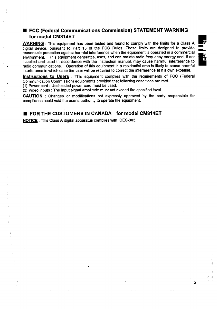
■ FCC (Federal Communications Commission) STATEMENT WARNING
for model CM814ET
WARNING :
digital device, pursuant to Part 15 of the FCC Rules. These limits are designed to provide =
reasonable protection against harmful interference when the equipment is operated in a commercial environment. This equipment generates, uses, and can radiate radio frequency energy and, if not installed and used in accordance with the instruction manual, may cause harmful interference to
radio communications. Operation of this equipment in a residential area is likely to cause harmful
interference in which case the user will be required to correct the interference at his own expense.
Instructions to Users : This equipment complies with the requirements of FCC (Federal
Communication Commission) equipments provided that following conditions are met.
(1) Power cord : Unshielded power cord must be used.
(2) Video inputs: The input signal amplitude must not exceed the specified level.
CAUTION : Changes or modifications not expressly approved by the party responsible for
compliance could void the user’s authority to operate the equipment.
This equipment has been tested and found to comply with the limits for a Class A ■
E
E
■ FOR THE CUSTOMERS IN CANADA for model CM814ET
NOTICE: This Class A digital apparatus complies with ICES-003.
5
Page 8

■ FOR THE CUSTOMERS IN THE U.K.
_ THIS PRODUCT IS SUPPLIED WITH A TWO PIN MAINS PLUG FOR USE IN MAINLAND
EUROPE. FOR THE U.K. PLEASE REFER TO THE NOTES ON THIS PAGE.
a
4
-
4
—
The mains lead on this equipment is supplied with a moulded plug incorporating a fuse, the value
of which is indicated on the pin face of the plug. Should the fuse need to be replaced, an ASTA or
the same colour as that visible on the pin face of the plug. Fuse covers are available from your
dealer.
WORDING FOR CLASS I EQUIPMENT INSTRUCTION BOOKS AND LABELS
BSI approved BS 1362 fuse must be used of the same rating. If the fuse cover is detachable
never use the plug with the cover omitted. If a replacement fuse cover is required, ensure it is of
DO NOT cut off the mains plug from this equipment. If the plug fitted is not suitable for the power
points in your home or the cable is too short to reach a power point, then obtain an appropriate
safety approved extension lead or consult your dealer.
Should it be necessary to change the mains plugs, this must be carried out by a competent person,
preferably a qualified electrician.
If there is no alternate to cutilng off the mains plug, ensure that you dispose of it immediately,
having first removed the fuse, to avoid a possible shock hazard by inadvetient connection to the
mains supply.
IMPORTANT FOR UNITED KINGDOM
WARNING: THIS EQUIPMENT MUST BE EARTHED
IMPORTANT
The wires in the mains lead are coloured in accordance with the following code:
Green and Yellow = Earth, Blue= Neutral, Brown = Live.
Green & Yellow
to Earth
Blue to Neutral
As these colours may not correspond with the coloured markings identifying the terminals in your
plug, proceed as follows:
The wire which is coloured GREEN and YELLOW must be connected to the terminal in the plug
which is marked with the letter E or by the earth symbol @ or coloured GREEN or GREEN and
YELLOW.
The wire coloured BLUE must be connected to the terminal marked with the letter N or coloured
BLUE or BLACK. The wire coloured BROWN must be connected to the terminal marked with the
letter L or mloured BROWN or RED.
Brown to Live
Fuse
Cord Clamp
6
Page 9

Page 10

L INSTALLATION ‘
Install the monitor in the following w
—
FRONT VIEW
1.Installation
Install the monitor on a horizontal base.
2. Power Cord Connection
@ Make sure of using the power cord meeting the safety standard of the
country in which you are using the monitor.
@ Insert the connector of a power cord to the AC Inlet of the monitor.
@ Insert the plug of the power cord to a receptacle of the correct voltage.
3. Signal Cable Connection
@ Use video signal cable which is included in the carton box.
(Cable model name: HD-0501 FXL)
@ Insert the connector of a signal cable to the Signal Input Connector of the
monitor, with attention to the suitability, and secure the screws on the
connector shell firmly.
@ Connect the other connector end of the signal cable to the host computer.
, taking care to maintain safety.
Rear Cover
Signal Input
Connector
AC inlet
\
-1
(
REAR VIEW
/
i
\
A receptacle of
the correct voltage
\
g+m
o
8
AC Inlet
Power Cord
\
i
\.
/
n
I
Signal Input
Connector
Signal Cable
to the host computer
Page 11

● Use a signal cable with the D-Sub Mini 15-pin Connector.
l“, ,,,
Inm-mnarti~n
N(.““,,,, ””.,.
5
6 Red Ground
7 Green Groul
Rl, ka (km Inr
-,-” -, ””,,
8
9
No connect~n
10
Ground
“.
e
● If the graphics board supplies more than one type of sync. signal, the sync,
signal type will be automatically selected by the monitor, with the priority
shown in”the following table.
Sync. Signal Type
H, V Separate Sync.
H I V Composite Sync.
Sync. on Green Video
4. Power On
Turn on the Power Switch of the monitor first, then the computer.
Refer to Page I.1 “POWER ON/OFF.
NOTICE :
■ After turning OFF the switch, wait at least 5 seconds to restart the monitor.
Otherwise the monitor may operate unusually.
■ If the picture doesn’t appear, turn OFF the power switch, make
following and wait at least 30 seconds to
Make sure
connection and the input sync. signal are right.
■ If the Colour is impure on the screen after turning ON the monitor, wait for about
10 minutes and press the
the power switch of the computer, power cord connection, signal cable
Priority
1
2
3
Degauss button.
No connection
Bi-directional Data [SDA]
;;
13 H.Sync. (or H/V)
v Sy
14
Datan;iock [SCL]
15
restart the monitor.
Id
PJcW
I
sure of the
Page 12

STANDARD SETTINGS
Microprocessor-based preset functions can store 26 sets of geometry settings
including the standard settings.
been pre-programmed by the factory.
Video Mode Name
~ Y)
The following industrial standard settings have
ET
3 VESA 1024X 768 -85
4 ADDle 1152x 870 -75
;=
. .
5 VESA 1280X 1024 -&j
6 VESA 1600X 1200 -75 Hz 93.75 kHz
7 VESA 1600X 1200 -85 Hz
8 VESA 1600X 1200.90 Hz
9
10
1856x1392 -71
1600x 1200-100
t+z 68.68 kHz
I+z 68.68 kHz Macintosh h – – –
E
HZ 91.15 kHz
106.25 kHz
112.50 kHz
102.95 kHz
I-Iz
125.00
Hz
kHz
~~ E‘~
21 Color
VESA
VESA
VESA
VESA
L
L –
–
– –
—
—
“~ “~
b b .J
–
h
—
— —
–
b
b
–
–
■ Input signals with approximately the same frequencies may be regarded as the
same signal.
The following horizontal timing conditions are recommended (at sync. H, V
separate or H/V composite).
for 31 kHz -55 kHz horizontal frequency:
Horizontal front porch should be more than 0.1 ps.
Horizontal sync. width should be within 1.0- 3.8 ps.
Horizontal back porch should be more than 1.2 ps.
Horizontal blanking width should be more than 3.5 ps.
for 55 kHz -125 kHz horizontal frequency:
Horizontal front porch should be more than 0.1 ps.
Horizontal sync. width should be within 0.8- 3.0 ps.
Horizontal back porch should be more than 1.1 ps.
Horizontal blanking width should be more than 2.4 ps.
The following vertical timing conditions are recommended.
Vertical front porch should be more than 9 ps.
Vertical sync. width should be less than 100 VS.
Vertical back porch should be more than 400 ps.
Vertical blanking width should be more than 450 ps.
In case the front or back porch is extremely long, or the data display time is
extremely short, it may not be able to set the expected size and position.
Standard settings are subject to change without notice.
This monitor is tested and conformed compliance with ZH1/618 and EN29241-3
(1S09241 -3) ergonomics requirement on the following video modes :
“VESA 1024X 768-85
“VESA 1280X 1024-85 tiz”
‘VESA 1600x 1200-85 Hz” (CM812ET, CM813ET and CM814ET onlv)
Hz”
&
,4
L
?0
Page 13

~ Control Switches
1
Oooooo m 00 o~o
I
i
(
/
\
~
—
-
\
&@9@@:~:m @*@
1
\
.. —-
1 1 1
1
I
Select Switch
Page 11-14 “ADJUSTMENT Page 11 “POWER ONIOF~
1
I
———
I I
1
Adjust Switch
e@
Q“@ :
I
Page 11 “DEGAUSSING’
I
/
POWER ON/OFF
Press the Power switch, to switch the power ON or OFF.
❑ When power is ON, the power LED lights.
DEGAUSSING
Press the switch ‘tDEGAUSS”, to degauss manually.
■ Use this function only
monitor. Remember, the monitor is automatically degaussed during initialpower on.
when you see colour impurities on the screen after turhing ON the
■ Wait for about 10 minutes before repeating the function.
ADJUSTMENT
Press the select switch of the item you want to adjust. Then you can adjust
by the adjust switches shown
■ You can store the adjusted condition. Refer to Page 15 “STORE”.
■ The On Screen Display function of “EasyMenu” shows ,
selected items and adjusting conditions. You can select ~10B .~=~+ ~
the EasyMenu Language. See the table below.
~ ~ @*$+’@ 1..5:..:-:
Select
Select
Item
LanguageSelect =and@ ~
Switch
simultaneously. ,
in following tables.
Adjust
AdjustSwitch
~
~ e~
@
:
;@ mode.
................................................2
......1
Sample of “EasyMenu”
Function
changes the language to the next
ENGLISH+ DEUTSCH+ESPAfiOL
+lTALIANO+FRAN~AIS
changesthe
languageto the previousmode.
FRANQAIS+lTALIANO+ ESPA~OL
+DEUTSCH+ENGLISH
11
Page 14

ADJUSTMENT (Continue)
—
—
Item
Contrast
Brightness
H. Position
-
Select
Switch
@@
Adjust Switch
@ Q
makes Contrast brighter excluding background.
:@
i e!
!@ !
@) ~ I ~ I makes Brightness darker including background. I
makes Contrast darker excluding background,
makes Brightness brighter including back-ground
~@ moves the position to the right.
Function
.
H. Size
V. Position
Size
V.
Rotation
Pincushion
Trapezoid
Right
Pincushion
Right
Trapezoid
@a
~
q /
~ e!
@ ~
@l/
@l ~
~
‘@l ~
~
@l :
@~l~
shrinks horizontally.
moves the position up.
;@
moves the position down.
expands vertically.
shrinks vertically.
rotates clockwise.
@ curves the Ieftlright sides outwards.
curves the Ieftlright sides inwards.
expands the top side, and
shrinks the bottom side.
@ curves the right side outwards.
expands the right top side, and
shrinks the riaht bottom side.
shrinks the right top side, and
expands the right bottom side.
m
m
m,
ml
ml
ml
ml
El
72
Page 15

All II I.QTMFNT (Cnntinlw.)
,
.-”-” . ,.. -.= . \--, .”,.--/
Select
Item
;olorSelect
Switch
B \ ~
.
Red ~and~ ~ :
simultaneously. j
When Green or ! :
Blue is selected, ~ :
@@is valid
singly.
Green
>olor
3alanca
Blue ~and~ : ;
Color
Reset Blue is selected
~and~ g :
simultaneously. j
When Blueor : j
Red is selected, j
mis valid
singly.
simultaneously. :
When Green or i ;
Red is selected, ~
@is valid
singly.
(This operation is ; :
valid only when
Green or
Red,
already.)
AdjustSwitch
G Q
changes
@ No.fl,9300K + No.2:6500K
- NO.3:5000K
+ No.4:USER (if available)
changes the colour to the previous
~ e~ mode.
No.4:USER (if available)
+ No.3:5000K + No.2:6500K
+ No.I :9300K
makes the Red stronger. When the
:@ Red reaches the upper limit, it makes
the Green and Blue weaker.
makes the Green and Blue stronger.
~ e: When the Green or Blue reaches the
Function
the colour to the next mode.
upperlimit,itmakes the Red weaker.
makes the Green
stronger. When the
:@ Greenreachesthe upperlimit,it makes
the Blueand Red
j E$ When the Blue or Red reaches the
: e! When the Red or Green reaches the
(+)
,
simultaneously,
for about
2 seconds.
makes the Blue and Red stronger.
upper limit, it makes
the Blue stronger. When the
makes
:@ Blue reaches the upper limit, it makes
the Red and Green weaker.
makes the Red and Green stronger.
upper limit, it makes the Blue weaker.
cancels the currently adjusted
andcallsthe colourconditionofthe
previously selected colour mode.
weaker.
the Green weaker.
,
colour,
■ When Ea6yMenu is not shown, you can start the adjustment of Contrast and
Brightness only, without pressing any select switch.
■ It is recommended to followthe following procedures for the adjustment of distortions
(1) “Rotation”
(2) “Pincushion” and “Trapezoi& (Adjust the left side.)
(3) “Right Pincushion” and “Right Trapezoid” (Adjust the right side.)
■ The mode “No.4:USER” is not factory set, and it is programmable if desired.
After adjustment of “Color Balance” (Red, Green or Blue) and “STORE” (refer to
page 15), your colour balance will be restored by selecting “No.4:USER”.
13
Page 16

ADJUSTMENT (Continue)
Select
i
Item
z H. Moire
~ Reduction
Switch
@and@@
simultaneously.
-r
V. Moire
Reduction
@@and@@
simultaneously.
“-i
Moire may appear on the screen due to interference between CRT dot Ditch and
video signal by conditions of video image, display size, display brightness, etc.
Adjust the conditions of display size, display brightness, etc., before the
adjustment of moire.
In some cases, this function may cause deterioration of display quality, such as
focus, jitter, etc.
The condition of the moire changing circuit will be indicated by pressing any
switch (Select Switch or Adjust Switch), as the following.
Indicated symbol
m:
m’
m“
Moire changing circuit condition :
Horizontal
ON
ON OFF
OFF ON
Adiust Switch
_i_M-
Vertical
ON ; 50 E14
operates the horizontal more changing
stops the horizontal moire changing
===
circuit.
makes the operation of the horizontal
moire changing circuit stronger.
makes the operation of the horizontal
moire changing circuit weaker.
operates the vertical moire changing
stops the vertical moire changing
G-
makes the operation of the vertical
moire changing circuit stronger.
makes the operation of the vertical
moire chanaina circuit weaker.
. ..............................................
CDCONTRAST +
:100 -4
: .......................................J
Y
~>+ :
BR IGHTNESS j
~
~)i3 :
{ 80
kllz/ 75Mz ;
Sample of “EasyMenu”
>
not indicated
OFF
OFF
Page 17

STORE
Your settinus will automatically be stored when the easv menu disatmears.
Item Storing Condition.
H,Position One setting is allowed for each video mode. When the monitor
H.Size
V. Position
V.Size
Pincushion
Trapezoid
Right Pincushion
Right Trapezoid
H.Moire Reduction
V. Moire Reduction
Color Balance
(Red, Green, Blue)
Rotation One setting is allowed.
Contrast
Brightness
Color Select
Language Select
You can store maximum 26 sets of geometry
settings including the standard settings (refer to
page 10 “STANDARD SEITINGS”).
■ If your store is at its maximum already, storing
a setting for new video mode overwrites the
oldest user setting.
W The video mode is distinguished by the
horizontallveitical frequency and polarity of the
horizontal[vertical sync. signal,
When the video modes are almost similar in
these factors, however, the video modes may
not be discriminated as different.
One setting is allowed to the Colour balance
“NO.4:USER”.
One setting is allowed.
■ It is normally not necessary to store them
manually. No operation of about 8 seconds
stores the currently adjusting data of these
items. automatically.
Restoring Condition
detects the same video
mode.
When the colour balance
“No.4USEW is selected.
When the monitor
detects a valid signal.
RECALL
To select the factory preset for the current video mode, press @ and @
simultaneously and hold for two seconds.
deleted.) The user can then restore new data if required.
(No other user settings are
RESET
To reset all user stored settings, turn QJ the @X@
Power switch while pressing E3 and @
simultaneously.
All user stored settings for
+w+$
each video mode, will be deleted when recalling the factory presets. The user
can then restore new data if required.
QUICK STORE
To store your settings quickly, Press the same select switch again.
15
Page 18

SIGNAL CHECK
To refer to the input signal condition, press any switch
– (Select Switch or Adjust Switch). The horizontal
~ frequency and vertical frequency will be indicated.
—
—
Precision frequency,
■
Horizontal approximately & 2 kHz
Vertical approximately
AUTOMATIC SIGNAL CHECK
When the monitor I
monitor will indicate
as detected the change of the si{
he condition automatically, as follc
*2Hz
. ....................................
0 CONTRAST ;
100 -<~}+ :
~ BR IGHTNESS \
5@ E4~}la ;
S0 kllz/ 75Hz !
. . .... ....... . .. ..\..............
Sample of
“EasyMenu”
Ial input condition, the
/s.
Condition
When the monitor detects
no sync. signal.
When the monitor will go
into the power saving
mode.
(Refer to page 17)
When the monitor detects
a sync. signal which is ou~
of set-up specification or
F
is unstable.
VIDEO MUTING
When the monitor has detected the change of the signal input condition, the
monitor mutes the picture automatically.
This function hides scrambled images which may appear during the changing
period of the input signal.
The muting period depends on the time that takes until the replaced signal
becomes stable.
The EasyMenu indicates the message
“POWER SAVE” for 5 seconds.
■ Verify power switch of the computer
and cable connection.
The LED of the Dower switch [@)
flashes.
■ Verify power switch of the computer
and cable connection.
The EasyMenu indicates the message
“INVALID
■ Verify
Indication
SCAN FREQ.”.
the specificationof inputsignal.
E
POUJER SfWE
—
INUfILI D SC9N FREQ .
I
I
I
I
Page 19

L POWER SAVING SYSTEM ‘
This monitor complies with VESA and ENERGY STAR@ power saving
requirements. The power saving system works only when used with VESA
DPMS compliant PC’s and/or graphic controllers.
“Note: When monitor is switched off by use of the Power Switch during the Power
9
Saving ‘OFF mode, the LED will sometimes continue to flash for a few seconds.
This is not a failure”.
Power Saving States
Power LED
Mode Video
VESA DPMS
H. Sync.
V. Sync. Power
ON Active
Stand-by Blanked
Suspend Blanked
OFF Blanked
Yes
No
Yes
No
Yes 125 W (typical) Lighting Green
Yes
No
No less than 5 W
less than
15W
Flashing quickly
Flashing Slowly
This monitor complies with VESA DDC1/2B specifications. Plug & Play is a
system with computer, peripherals (including monitors), and operating system.
It works when the monitor is connected to DDC ready computer that is running
an operating system software that incorporates plug & play functionality.
1
L
17
Page 20

_ CRT
a
4
-
~ Input Signal
Synchronisation
Resolution
Video Clock frequency
Viewable Image Size
Viewable Image Area
Colour Temperature
21 inch picture tube, 0.22 mm horizontal dot pitch
(0.21 mm horizontal mask pitch),
Invar shadow mask, Black matrix,
phosphors, New Anti-Reflection coat.
Video
Sync.
Horizontal:
Vertical :
Horizontal:
Vertical :
20.0 inches (508 mm), diagonal (typical)
Horizontal : 406 mm (typical)
Vertical : 305 mm (typical)
Standard Colour Balance 1 : 9300K
Standard Colour Balance 2 : 6500K
Standard Colour Balance 3 : 5000K
Colour Balance 4 :
: 0.70 Vp-p, Analogue
: Separate HAl, lTL level
ComDosite H/V. TTL level
Sync. on Green at 0.30 Vp-p
CM81 IET CM812ET CM813ET
31-96 kHz 31-107 kHz 31-115 kHz
50-160
CM811 ET CM812ET CM813ET
1280 lines 1280 lines 1392 lines
CM811 ET CM812ET CM813ET
Hz 50-160 HZ 50-160 Hz
1600 dots 1600 dots 1856 dots
(max.)
200 MHz
(typical)
(max.) (max.)
230 MHz 250 MHz
(typical) (typical)
User defined
Short
persistence
CM814ET
31-125 kHz
50-160
tiz
CM814ET
1856 dots
1392 lines
(max.)
CM814ET
270 MHz
(typical)
Warm-up Time
Power Supply
Dimensions
Weight
Environmental
Condition
Specification and Design are subject to change without notice.
?8
30 minutes to reach optimum performance level.
AC 100- 120/ 200-240 V, automatically selected.
Power Consumption :125 W (typical)
Provided with power save circuit.
488 (W) X 482 (H) X 470 (D) mm
(including Tilt & S~vel Base)
27.5 kg (approx.)
(including Tilt & Swivel Base)
O~eration
Temperature
Humidity 10% to 80%
5°Cto 40°c
S!!2M!2
–20”C to 60°C
10’%0to 90?40
,;
Page 21

Hitachi, Ltd. Tokyo, Japan
International Sales Division
THE HITACHI ATAGO BUILDING,
No. 15 –12 Nishi Shinbashi, 2 – Chome,
Minato – Ku, Tokyo 105-8430, Japan.
Tel: 03 35022111
HITACHI EUROPE LTD,
Whitebrook Park
Lower Cookham Road
Maidenhead
Berkshire
SL6 8YA
UNITED KINGDOM
Tel: 01628 643000
Fax: 01628 643400
Email: consumer-service@hitachi-eu.com
HITACHI EUROPE GmbH
Munich Office
Dornacher Strasse 3
D-85622 Feldkirchen bei München
GERMANY
Tel: +49-89-991 80-0
Fax: +49- 89-991 80-224
Hotline: +49-180-551 25 51 (12ct/min)
Email: HSE-DUS.service@hitachi-eu.com
HITACHI EUROPE srl
Via Tommaso Gulli N.39, 20147
Milano, Italia
ITALY
Tel: +39 02 487861
Tel: +39 02 38073415 Servizio Clienti
Fax: +39 02 48786381/2
Email: customerservice.italy@hitachi-eu.com
HITACHI EUROPE S.A.S
Lyon Office
B.P. 45, 69671 BRON CEDEX
FRANCE
Tel: 04 72 14 29 70
Fax: 04 72 14 29 99
Email: france.consommateur@hitachi-eu.com
HITACH EUROPE AB
Egebækgård
Egebækvej 98
DK-2850 Nærum
DENMARK
Tel: +45 43 43 6050
Fax: +45 43 60 51
Email: csgnor@hitachi-eu.com
Hitachi Europe Ltd
Bergensesteenweg 421
1600 Sint- Pieters-Leeuw
BELGIUM
Tel: +32 2 363 99 01
Fax: +32 2 363 99 00
Email: sofie.van.bom@hitachi-eu.com
www.hitachidigitalmedia.com
HITACHI EUROPE S.A.
364 Kifissias Ave. & 1, Delfon Str.
152 33 Chalandri
Athens
GREECE
Tel: 1-6837200
Fax: 1-6835964
Email: service.hellas@hitachi-eu.com
HITACHI EUROPE S.A.
Gran Via Carlos III, 101- 1
08028 Barcelona
SPAIN
Tel: 93 409 2550
Fax: 93 491 3513
Email: atencion.cliente@hitachi-eu.com
HITACHI Europe AB
Box 77 S-164 94 Kista
SWEDEN
Tel: +46 (0) 8 562 711 00
Fax: +46 (0) 8 562 711 13
Email: csgswe@hitachi-eu.com
HITACHI EUROPE LTD (Norway) AB
STRANDVEIEN 18
1366 Lysaker
NORWAY
Tel: 67 5190 30
Fax: 67 5190 32
Email: csgnor@hitachi-eu.com
HITACHI EUROPE AB
Neopoli / Niemenkatu 73
FIN-15140 Lahti
FINLAND
Tel : +358 3 8858 271
Fax: +358 3 8858 272
Email: csgnor@hitachi-eu.com
HITACHI EUROPE LTD
Na Sychrove 975/8
101 27 Praha 10 – Bohdalec
CZECH REPUBLIC
Tel: +420 267 212 383
Fax: +420 267 212 385
Email: csgnor@hitachi-eu.com
 Loading...