

Page 1
6(59,&(0$18$/
J
0$18(/'·(175(7,(1
:$5781*6+$1'%8&+
&$87,21
%HIRUH VHUYLFLQJ WKLV FKDVVLV LW LV LPSRUWDQW WKDW WKH VHUYLFH WHFKQLFLDQ UHDG
WKH ´6DIHW\ 3UHFDXWLRQVµ DQG ´3URGXFW 6DIHW\ 1RWLFHVµ LQ WKLV VHUYLFH PDQXDO
$77(17,21
$YDQW G·HIIHFWXHU O·HQWUHWLHQ GX FKkDVVLV OH WHFKQLFLHQ GRLW OLUH OHV
©3UpFDXWLRQV GH VpFXULWpª HW OHV ©1RWLFHV GH VpFXULWp GX SURGXLWª SUpVHQWpV
GDQV OH SUpVHQW PDQXHO
1R
&/:7$1
&/:7$1
&/:7$1
&/:7$1
&:71
&:71
'DWD FRQWDLQHG ZLWKLQ WKLV 6HUYLFH
PDQXDO LV VXEMHFW WR DOWHUDWLRQ IRU
LPSURYHPHQW
/HV GRQQpHV IRXUQLHV GDQV OH
SUpVHQW PDQXHO G·HQWUHWLHQ
SHXYHQW IDLUH O·REMHW GH
PRGLILFDWLRQV HQ YXH GH
SHUIHFWLRQQHU OH SURGXLW
9256,&+7
9RU gIIQHQ GHV *HKlXVHV KDW GHU 6HUYLFH,QJHQLHXU GLH Å6LFKHUKHLWVKLQZHLVH´
XQG Å+LQZHLVH ]XU 3URGXNWVLFKHUKHLW´ LQ GLHVHP :DUWXQJVKDQGEXFK ]X OHVHQ
'LH LQ GLHVHP :DUWXQJVKDQGEXFK
HQWKDOWHQHQ 6SH]LILNDWLRQHQ
N|QQHQ VLFK ]ZHFNV
9HUEHVVHUXQ
HQ lQGHUQ
7(&+1,&$/ 63(&,),&$7,216 63e&,),&$7,216 7(&+1,48(6 63(&,),&$7,216 7(&+1,48(6
79 6WDQGDUG
&KDQQHO FRYHUDJH
$HULDO LQSXW LPSHGDQFH
3URJUDPPH 6HOHFWRUV
3RZHU &RQVXPSWLRQ 3LFWXUH 7XEH &RQVRPPDWLRQ
:
:
:
:
:
:
6WDQGE\ 3RZHU &RQVXPSWLRQ :
0DLQV 9ROWDJH99 +]
)XVH 7$ 7\SH
)RFXVLQJ(OHFWUR VWDWLF
8+)9+) +\SHU EDQG ([SRUW
EXWWRQV ZLWK SURJUDPPH
)UHTXHQF\ GLUHFW LQSXW
7%$
:
:
7%$
:
:
%*+ // ([SRUW
8+) &KDQQHOV 8.
&KDQQHO 83'2:1
OLQHV
67$1'$5' , 8.
RKP
8QEDODQFHG
UHPRWH FRQWURO
&+ GLUHFW LQSXW
FP 7\SH
FP 7\SH
FP 7\SH
FP 7\SH
FP 7\SH
FP 7\SH
6WDQGDUG 79 OLJQHV
&RXYHUWXUH GH FDQDX[ &DQDX[ 8+) 58
,PSpGDQFH GHQWUpH GDQWHQQH RKPV
6pOHFWHXUV GH SURJUDPPHV 7RXFKHV GH
pOHFWULTXH
:
:
:
:
:
:
&RQVRPPDWLRQ HQ PRGH YHLOOH :
7HQWLRQ VHFWHXU99 +]
)XVLEOH 7\SH 7 $
0LVH DX SRLQW(OHFWURVWDWLTXH
67$1'$5' 58
%*+ // ([SRUW
8+)9+) %DQG K\SHU ([SRUW
1RQ pTXLOLEUpH
6pOHFWLRQ GH FDQDX[ +$87%$6
$YHF SURJUDPPHV
(QWUpH GLUHFWH FDQDO &+
7%$
:
:
7%$
:
:
7pOpFRPPDQGH
(QWUpH GLUHFWH IUpTXHQFH
7XEHVLPDJHV /HLVWXQJVDXIQDKPH %LOGU|KUH
FP 7\SH
FP 7\SH
FP 7\SH
FP 7\SH
FP 7\SH
FP 7\SH
)HUQVHKQRUP =HLOHQ
.DQlOH 8+)%HUHLFK *%
8+)9+)+\SHUEDQG%HUHLFK ([SRUW
$QWHQQHQHLQJDQJVLPSHGDQ] RKQ
6HQGHUZDKO$8)$%7DVWH
:
:
:
:
:
:
/HLVWXQJVDXIQDKPH LP 6WDQGE\0RGXV :
1HW]VSDQQXQJ 9 9 +]
6LFKHUXQJ 7$
)RNXVLHUXQJ(OHNWURVWDWLVFK
DXI )HUQEHGLHQXQJ IU 6HQGHU
)HUQVHKQRUP , QXU *%
)HUQVHKQRUP %*+ //
8QV\PPHWULVFK
6HQGHUGLUHNWHLQJDEH
)UHTXHQ]GLUHNWLQJDEH
7%$
:
:
7%$
:
:
FP 7\SH
FP 7\SH
FP 7\SH
FP 7\SH
FP 7\SH
FP 7\SH
0D\
Page 2

ENGLISH .............................................................................................................................................3
SAFETY ............................................................................................................................................3
SAFETY PRECAUTIONS ..............................................................................................................................3
CIRCUIT DESCRIPTION...................................................................................................................4
D8/A8 CHASSIS ALIGNMENT PROCEDURE ................................................................................................4
DIGITAL COMB FILTER – TOSHIBA TC9090AF..........................................................................................13
SCAN VELOCITY MODULATION. ...............................................................................................................13
DIGITAL DOUBLE SCAN CONVERSION UNIT (FEATURE BOX).................................................................13
INPUT PROCESSOR - PHILIPS TDA 9320..................................................................................................14
PICTURE IMPROVEMENT - PHILIPS TDA 9178..........................................................................................15
TUNER........................................................................................................................................................15
RGB PROCESSOR - TDA 9330...................................................................................................................15
SIGNAL PATH DESCRIPTION.....................................................................................................................16
AUDIO CIRCUIT..........................................................................................................................................16
AUDIO OUTPUT..........................................................................................................................................17
DOLBY DECODER. .....................................................................................................................................17
DEFLECTION..............................................................................................................................................17
HIGH END FEATURE BOX..........................................................................................................................18
LOW END FEATURE BOX ..........................................................................................................................18
MICROCONTROLLER SECTION ON THE A8/D8 CHASSIS ........................................................................19
POWERED CONSOLE................................................................................................................................26
DIGITAL SECTION...................................................................................................................................... 27
GENERAL BLOCK DIAGRAM......................................................................................................................28
COFDM FRONT-END PCB ..........................................................................................................................29
MPEG DECODER AND AV/GRAPHICS PCB............................................................................................... 37
CONNECTOR SPECIFICATION..................................................................................................................60
A8/D8 PSU ..................................................................................................................................................66
DTI PSU ......................................................................................................................................................67
SERVICING..................................................................................................................................... 69
SERVICE. ...................................................................................................................................................69
SELF DIAGNOSTICS ..................................................................................................................................71
DIAGNOSTIC INTERFACE..........................................................................................................................73
FRANÇAIS.........................................................................................................................................74
SÉCURITÉ......................................................................................................................................74
CONSIGNES DE SECURITE.......................................................................................................................74
DESCRIPTION DU CIRCUIT...........................................................................................................75
PROCEDURE D'ALIGNEMANT DU COFFRET D8/A8.................................................................................. 75
FILTRE-PEIGNE NUMÉRIQUE....................................................................................................................84
MODULATION DE LA VITESSE DE BALAYAGE..........................................................................................84
GROUPE DE CONVERSION NUMÉRIQUE À DOUBLE VISIONNEMENT (COFFRET DES FONCTIONS).... 84
PROCESSEUR D'ENTRÉE – PHILIPS TDA 9320 ........................................................................................85
AMÉLIORATION DE L'IMAGE - PHILIPS TDA 9178.....................................................................................86
TUNER........................................................................................................................................................86
PROCESSEUR RGB - TDA 9330.................................................................................................................86
DESCRIPTION DE LA TRAJECTOIRE DES SIGNAUX ................................................................................87
CIRCUIT AUDIO..........................................................................................................................................87
SORTIE AUDIO ...........................................................................................................................................88
DÉCODEUR DOLBY...................................................................................................................................88
DEFLEXION................................................................................................................................................89
CASE DE FONCTIONS EXTRÉMITÉ HAUTE ..............................................................................................90
CASE FONCTIONS EXTRÉMITÉ BASSE....................................................................................................90
SECTION DU MICROCONTRÔLEUR DU CHÂSSIS A8/D8.......................................................................... 91
CONSOLE D'ALIMENTATION .....................................................................................................................99
DESCRIPTION GÉNÉRALE ......................................................................................................................100
SCHÉMA SYNOPTIQUE ...........................................................................................................................101
CIRCUIT IMPRIMÉ FRONTAL COFDM......................................................................................................102
CIRCUIT IMPRIMÉ DE DÉCODEUR MPEG ET AV/GRAPHIQUES ............................................................110
SPÉCIFICATION DES CONNECTEURS....................................................................................................132
ALIMENTATION A8/D8..............................................................................................................................139
ALIMENTATION DTI..................................................................................................................................140
ENTRETIEN COURANT................................................................................................................142
SERVICE. .................................................................................................................................................142
AUTO-DIAGNOSTIC..................................................................................................................................146
1
Page 3

INTERFACE DE DIAGNOSTIC..................................................................................................................148
DEUTSCH........................................................................................................................................149
SICHERHEIT.................................................................................................................................149
SICHERHEITSVORKEHRUNGEN.............................................................................................................149
SCHALTUNGSBESCHREIBUNG .................................................................................................. 150
D8/A8 VERFAHREN ZUM GRUNDPLATTENABGLEICH ...........................................................................150
DIGITALER KAMMFILTER – TOSHIBA TC9090AF....................................................................................159
MODULATION DER ABTAST-GESCHWINDIGKEIT...................................................................................159
DIGITALES DOPPELABTASTUNGS-UMWANDLUNGS-AGGREGAT (ZUSATZ-KASTEN). ........................159
EINGABE-PROZESSOR - PHILIPS TDA 9320...........................................................................................160
BILDVERBESSERUNG - PHILIPS TDA 9178.............................................................................................161
TUNER......................................................................................................................................................161
RGB PROZESSOR - TDA 9330.................................................................................................................161
BESCHREIBUNG DES SIGNALWEGS......................................................................................................162
AUDIO-SCHALTKREIS..............................................................................................................................162
AUDIO-AUSGABE.....................................................................................................................................163
DOLBY DECODER. ...................................................................................................................................163
ABLENKUNG............................................................................................................................................163
„HÖHERE“ FEATURE BOX .......................................................................................................................165
„NIEDRIGE“ FEATURE BOX......................................................................................................................165
MIKROCONTROLLER-ABSCHNITT AUF DER A8/D8 GRUNDPLATTE......................................................166
MIT STROM VERSORGTE KONSOLE ......................................................................................................175
DIGITALER TEIL.......................................................................................................................................175
BLOCKSCHALTBILD.................................................................................................................................177
COFDM EINGANGS-FLACHBAUGRUPPE................................................................................................178
MPEG DECODER UND AV/GRAFIK FLACHBAUGRUPPE........................................................................187
STECKER-SPEZIFIKATION ......................................................................................................................210
A8/D8 NETZTEIL.......................................................................................................................................217
DTI-NETZTEIL...........................................................................................................................................218
WARTUNG....................................................................................................................................220
WARTUNG................................................................................................................................................220
SELBST-DIAGNOSE.................................................................................................................................223
DIAGNOSE-SCHNITTSTELLE...................................................................................................................224
WAVEFORMS............................................................................................................................... 225
IC DATA........................................................................................................................................ 230
I200...........................................................................................................................................................230
IE02..........................................................................................................................................................235
MECHANICAL............................................................................................................................... 238
2
Page 4

ENGLISHENGLISH
SAFETY
SAFETY PRECAUTIONS
WARNING: The following precautions must be observed.
ALL PRODUCTS
1. Before any service is performed on the chassis an isolation transformer should be inserted between the power line and
the product.
2. When replacing the chassis in the cabinet, ensure all the protective devices are put back in place.
3. When service is required, observe the original lead dressing. Extra precaution should be taken to ensure correct lead
dressing in any high voltage circuitry area.
4. Many electrical and mechanical parts in HITACHI products have special safety related characteristics. These
characteristics are often not evident from visual inspection, nor can the protection afforded by them necessarily be
obtained by using replacement components rated for higher voltage, wattage, etc. Replacement parts which have these
special safety characteristics are identified by marking with a ! on the schematics and the replacement parts list.
The use of a substitute replacement component that does not have the same safety characteristics as the HITACHI
recommended replacement one, shown in the parts list, may create electrical shock, fire, X-radiation, or other hazards.
5. Always replace original spacers and maintain lead lengths. Furthermore, where a short circuit has occurred, replace those
components that indicate evidence of overheating.
6. Insulation resistance should not be less than 2M ohms at 500V DC between the main poles and any accessible metal
parts.
7. No flashover or breakdown should occur during the dielectric strength test, applying 3kV AC or 4.25kV DC for two
seconds between the main poles and accessible metal parts.
8. Before returning a serviced product to the customer, the service technician must thoroughly test the unit to be certain that
it is completely safe to operate without danger of electrical shock. The service technician must make sure that no
protective device built into the instrument by the manufacturer has become defective, or inadvertently damaged during
servicing.
CE MARK
1. HITACHI products may contain the CE mark on the rating plate indicating that the product contains parts that have been
specifically approved to provide electromagnetic compatibility to designated levels.
2. When replacing any part in this product, please use only the correct part itemised in the parts list to ensure this standard
is maintained, and take care to replace lead dressing to its original state, as this can have a bearing on the
electromagnetic radiation/immunity.
PICTURE TUBE
1. The line output stage can develop voltages in excess of 25kV; if the E.H.T. cap is required to be removed, discharge the
anode to chassis via a high value resistor, prior to its removal from the picture tube.
2. High voltage should always be kept at the rated value of the chassis and no higher. Operating at higher voltages may
cause a failure of the picture tube or high voltage supply, and also, under certain circumstances could produce X-radiation
levels moderately in excess of design levels. The high voltage must not, under any circumstances, exceed 29kV on the
chassis (except for projection Televisions).
3. The primary source of X-radiation in the product is the picture tube. The picture tube utilised for the above mentioned
function in this chassis is specially constructed to limit X-radiation. For continued X-radiation protection, replace tube with
the same type as the original HITACHI approved type
4. Keep the picture tube away from the body while handling. Do not install, remove, or handle the picture tube in any manner
unless shatterproof goggles are worn. People not so equipped should be kept away while picture tubes are handled
LASERS
If the product contains a laser avoid direct exposure to the beam when the cover is open or when interlocks are defeated or have
failed.CIRCUIT DESCRIPTIONCIRCUIT DESCRIPTION
3
Page 5

CIRCUIT DESCRIPTION
D8/A8 CHASSIS ALIGNMENT PROCEDURE
APPLICATIONS
THIS SPEC. SHOULD BE APPLIED TO ALL UK AND EXPORT, A8 RECEIVERS
P.W.B ASSEMBLY ADJUSTMENT
FOR SIGNAL
PREPARATION ADJUSTMENT
• +B adj. VR982..........Centre
• Screen VR (FBT).......Counter-clockwise fully
• Turn on set. Adjust +B to approximately 152V. (Pre adjustment only - final adjustment in +B VOLTAGE ADJUSTMENT
section)
• If flaring is observed adjust L501 until a clean video signal is seen on the oscilloscope video out port.
For models which have a flash device fitted, ensure that the service information reads FLASH: x.x instead of Code: x.x for the
software version.
STANDARD AFC ALIGNMENT
To reduce the influence of circuit temperature drift, let the television warm up by leaving it operating normally for more than two
minutes.
• Receive a 'PAL I' signal by selecting program 3 via the remote control handset.
• Receive a signal level of +60 dBuV at 623,25MHz (CH40) by direct frequency entry under the CH option.
• Set AFC offset (in service - options) to the centre position.
• In the tuner menu select standard I.F AFC and press either '<' or '>' on the remote control to activate the automatic AFC
setting procedure.
• If the indicator bar goes either end, then returns to the centre, adjust L201 one turn and then return to step 3, continue this
until the indicator bar no longer jumps back to the centre.
L' AFC ALIGNMENT (FOR EXPORT MODELS ONLY).
• To reduce the influence of circuit temperature drift, let the television warm up by leaving it operating normally for more
than two minutes.
• Receive an L' signal by selecting program 14 via the remote control hand-set.
• Receive a signal level of +60 dBuV at 63,75MHz (CH4) by direct frequency entry under the CH option.
• In the tuner menu select L' I.F AFC and press '<' or '>' on the remote control.
• If the bar goes to either end then returns to centre, adjust L201 one turn and then return to step 3, continue this until the
Because the set up procedures are interactive it is necessary to repeat all procedures from STANDARD AFC ALIGNMENT until no
adjustment of L201 is required.
AGC ALIGNMENT
indicator bar no longer jumps back to the centre.
• To reduce the influence of circuit temperature drift, let the television warm up by leaving it operating normally for more
than two minutes.
• Connect a voltmeter of at least 100K internal resistance to the A.G.C. terminal of the tuner.
• Receive channel 40 (623.25mhz) at +60dBuV.
• Adjust the A.G.C. using the A.G.C take-over option in the tuner sub menu until the A.G.C. voltage is 2.8V +/- 0.1V.
4
Page 6
POWER AND DEFLECTION ADJUSTMENT
+B VOLTAGE ADJUSTMENT
• AC input voltage = 230V ± 5V/50Hz
• Turn +B voltage (R982) to mid-point (if pre-adjustment not done).
• Receive Philips circuit pattern. Switch on chassis and set the brightness and contrast to maximum.
• After applying heat run for 1 MIN. or more, turn R982 gradually and adjust +B (re-check after 30 secs)
Measuring point : +B voltage C958 + side
Gnd C958 - side
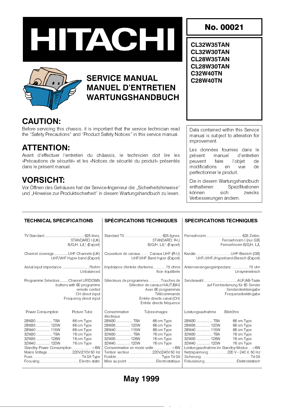
• Set the value of +B voltage to the value shown in the table below.
MODEL +B VOLTAGE (V)
All D8 151V ± 0.2V
All A8 148V ± 0.2V
Min Load Max Load
+8V = 8V ± 5%
+5V = 5V ± 5%
+16V = 16V ,+3V – 0.5V 0A 1.6A
+16V(Phono) = +16V, (+ 3V, - 1V) 0A 200mA
+B 0.2A 0.8A
• Check + B voltage in standby > 145V and < 160V.
Short circuit test (all rails). PSU should go into standby/reset/lockup (supply may have to be removed to restart). Audio rail should be
tested , Q921 source to 0V.
0.3A 0.8A
0.3A 0.8A
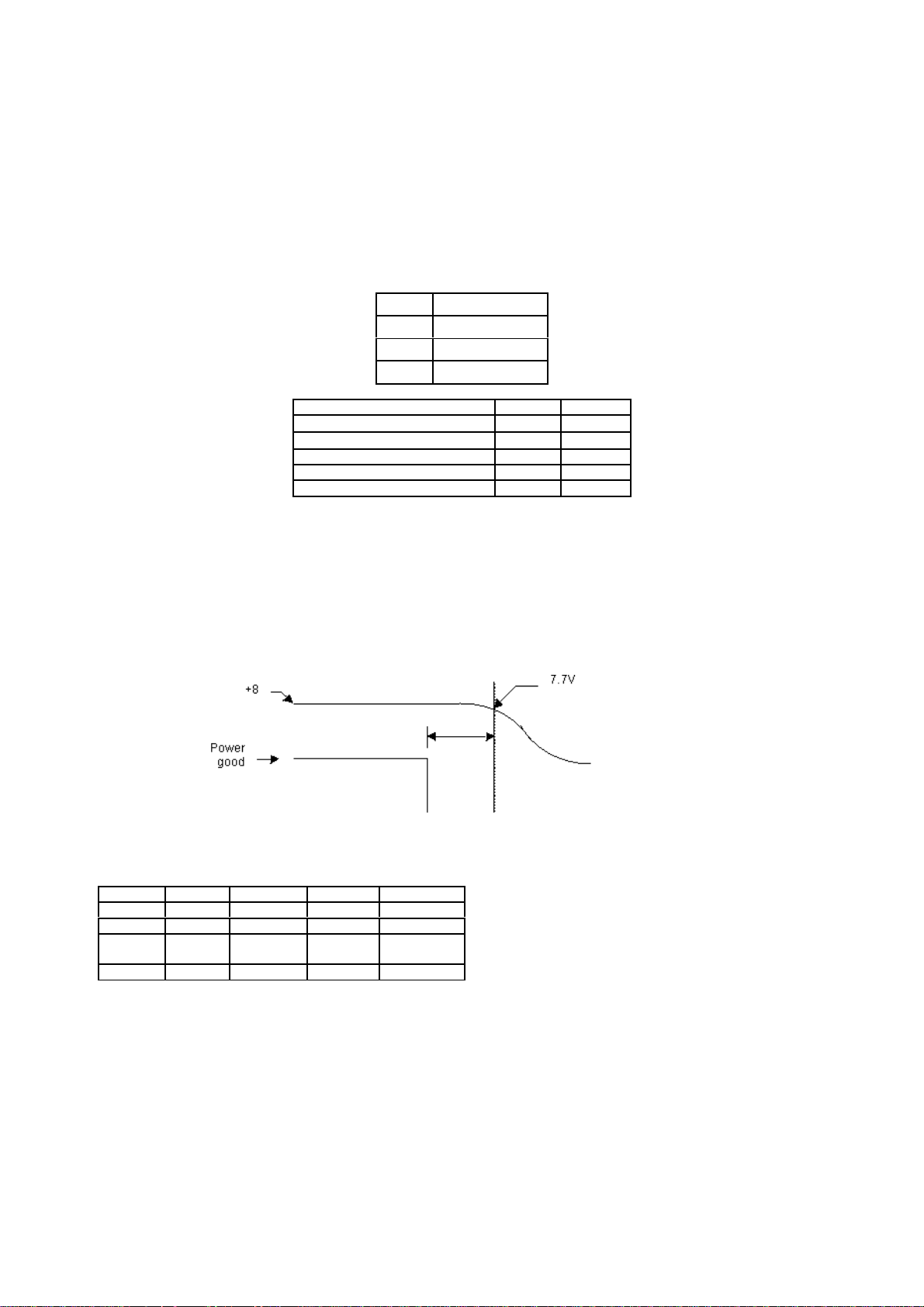
POWER AND DEFLECTION ADJUSTMENT
POWER GOOD LINE
PRIMARY CURRENT LIMIT
(Pre-set R980 to mid point)
Rail Trip Load Check Load Trip Power Check Power
+B 1.2ADC 1.1A 180W 165W
+16V 2.24ADC 1.65A 36W 26W
+11V
(+5, +8)
TOTAL W 234W 209W
• In standby apply full load +40%, to the +B & audio/+11V rails (dynamic load) as table above.
• Adjust R980 until set trips out .
• In standby apply check load. PSU should not trip.
• Set picture to same conditions as above.
• Measure pin 2 I903. Should be HI, if LOW then cut R962 (if fitted). If HI but no power down timing (see below)
then cut R955 (if fitted).
• Check power down logic timing ( >40mS, < 300mS )
• After setting power good , check operation at 200V AC mains
1.60A 1.60A 18W 18W
STANDBY OPERATION CHECK
• Check all rails (except +B and standby +5V) go to 0V.
• Check +B does not rise above 160V
5
Page 7
GENERAL SAFETY CHECKS
• High voltage BEAB test to confirm components across barrier (including sub board).
• Deg relay insertion orientation test (relay can be fitted inverted on main and sub PSU console stand). + Job instruction to
show orientation of relay.
SUB BOARD PSU CHECK (DTT/BASS/CONSOLE PSU)
• Short circuit test (all rails)
• Output voltage test (all rails), see table.
• Standby operation. All rails should be off. +10V remains to supply, sub PSU & opto.
• Full load operation check.
RAIL DTT BASS CONSOLE
38V / 0.62A 0.62A
32V / / 0.92A
9V 400mA / /
5.1V 1.5A Used for mute Used for mute
3V3 2.7A / /
30V 10mA / /
12V 10mA / /
DTT +5V SETTING
• Set VR1 to approx. centre position (10kΩ).
• Turn power on applying external load, see table.
• Adjust VR1 making sure +5.2V rail is within ± 0.05V.
SUB-BOARD MUST BE BEAB TESTED IN A SET OR CONSOLE STAND.
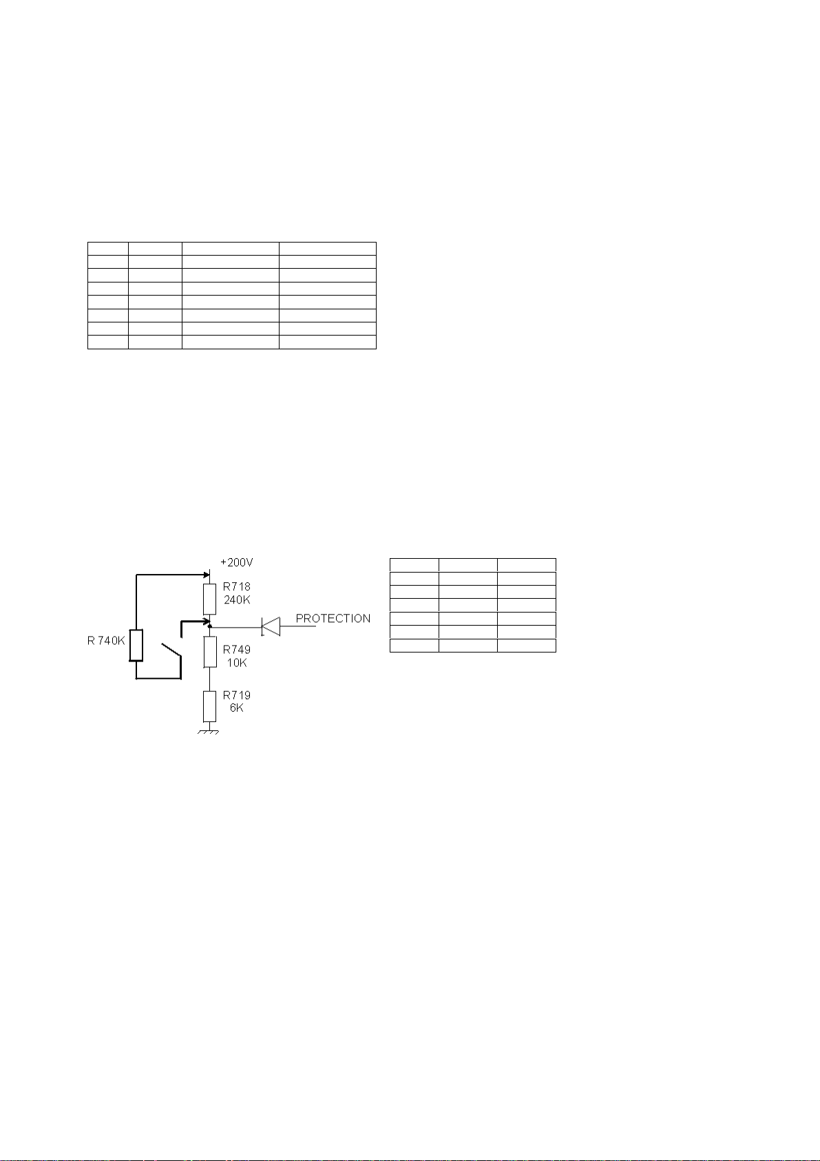
HIGH VOLTAGE LIMITER CIRCUIT CHECK
• Mount the PW board to the set and adjust normally.
• Receive the circle pattern signal.
• Set the contrast and brightness to maximum.
• Add R=470K in parallel with R718 and R718A.
• Check that picture and sound disappear when R is added.
NOTE:
High voltage limiter circuit jig:
2
25",28" 47K 4K7
28" 16/9 47K 4K7
32" 16/9 47K 4K7
ANODE/FOCUS SHORT-CIRCUIT TEST PROTECTION CIRCUIT CHECK
• Add a dc voltage to R760 until set trips ( The dc level should be equivalent to 1.7 x (+B current peak value )
0.6 VDC R760 SET SHOULD NOT TRIP
1.6 VDC R760 SET SHOULD TRIP
FINAL ANODE VOLTAGE LEVEL CHECK.
Please check on all A8 models that the final anode voltage does not exceed the voltages stated.
28" widescreen 31kV
32" widescreen 32kV
This test should be carried out with the brightness and the contrast set to minimum.
R719 R749
6
Page 8
FOR FEATURE BOX (A8 ONLY)
5V & 8V SHORT CIRCUIT CHECK USING FEATURE BOX BOARD
• Measure the resistance between 5V (EU11, pin1) and GND (EU11, pin3) by multi-meter. If the meter shows 62.5 ± 4Ω,
The FEATURE BOX is OK.
• Measure the resistance between 8V (EU11, pin6) and GND (EU11, pin3) by multi-meter. If the meter shows 1.29 ± 0.1kΩ,
If these resistance are not correct, Please check solder bridge or solder losing around IU03 (SDA9272).
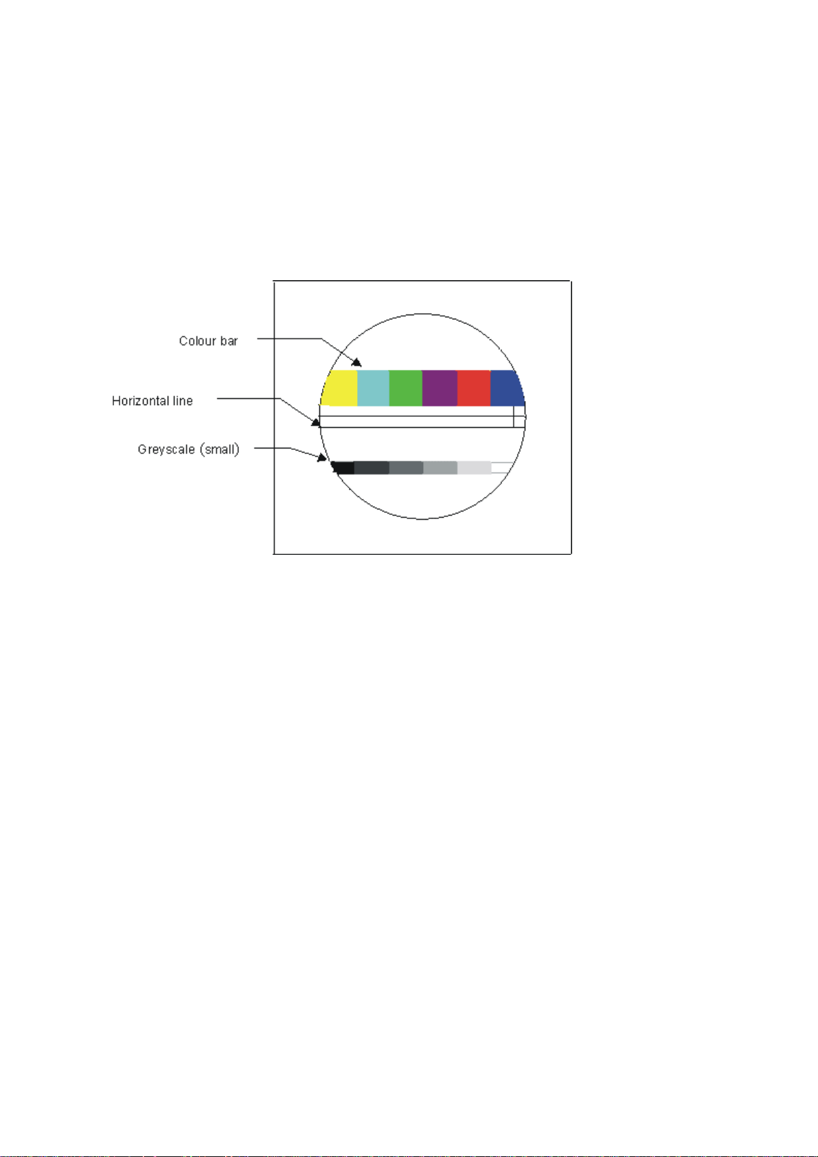
FEATURE BOX OPERATION CHECK
The FEATURE BOX is OK.
• Fit FEATURE BOX onto main board.
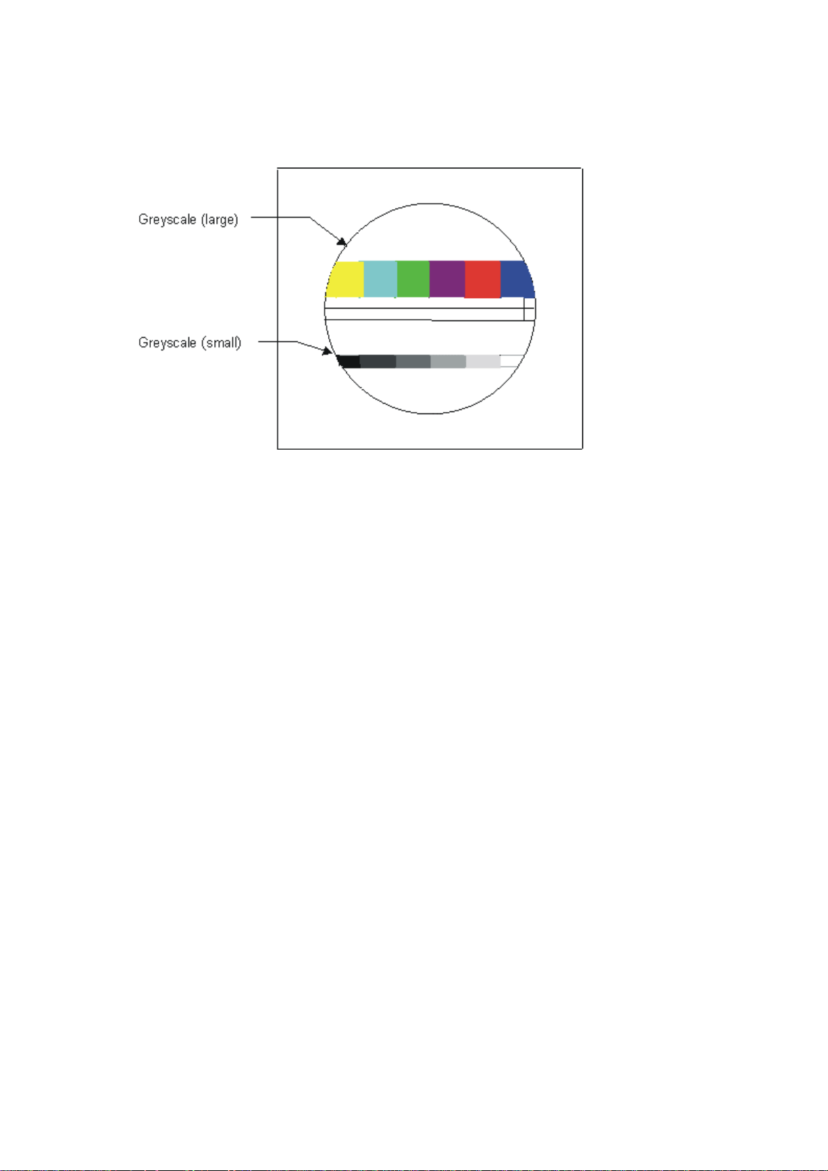
• Receiving circle pattern (PAL), checking the picture quality. Check: Horizontal line is stable (see horizontal line). <-----
Only for 2897,W35 models Colour bar part is correct (see colour bar). White part of picture is pure white(see greyscale).
• Check the progressive scan/100Hz operation by handset (scan-key) <----Only for 2897,W35 models.
• Change sharpness , CTI , compression (14:9, 4:3 & zoom), noise reduction (low, mid & high) by handset. Check the total
Receive an NTSC signal , check same items as PAL.
performance. Whenever digital noise is appears on the picture, or miss operation occurs, reject the feature box.
7
Page 9
PICTURE POSITION/SHAPE
HORIZONTAL PHASE
VERTICAL CENTRE
VERTICAL AMPLITUDE
• Wait 5 minutes minimum after switching on the mains before adjustment.
• Receive the Philips circle pattern.
• Set brightness and contrast to maximum.
• The set should face North or South.
• AC input should be 230V ± 5V 50Hz.
• Adjust software control (using PC / HAND SET)
• Adjust control so that the centre of the picture is as in the diagram below.
Note:
The picture should be exaggerated as to create a barrel type picture at the vertical edges. The compensation to achieve this barrel
picture should be 3 steps passed the normal vertical edge position. This is to compensate for the pin cushion effect noticeable on
the OSDs.
TILT
PARABOLA
WIDTH
• Allow 5 minutes warm up time before adjustment.
• Receive Philips circle pattern.
• Set brightness and contrast to nominal.
• The set should face North or South.
• AC input should be 230V ± 5V 50Hz.
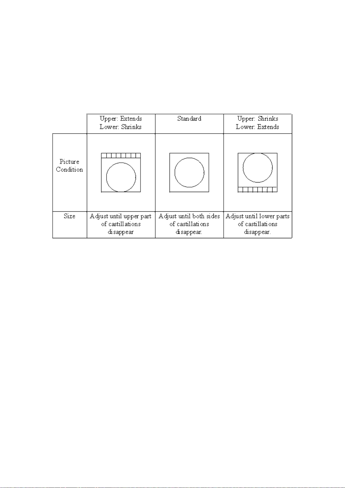
• Adjust software so that the vertical lines at the outside edges of the screen are adjusted to be roughly vertical.
• Adjust the software so that the (approximately) vertical lines at the sides of the screen are adjusted as vertical as the
centre of the screen.
• Adjust the software so that the castillations at the sides of the picture are not quite visible. Reduce the brightness and
contrast to make sure that the picture width has not reduced so that you can see beyond the castillations. You may have
NOTE. For all 16:9 receivers the picture should be first set up in 16:9 mode, then final adjustment for parabola and corner correction
only to be carried out in 4:3 mode.
to repeat stages 6 and 7 again.
8
Page 10
FOCUS ADJUSTMENT
• Receive the Philips circle pattern.
• Adjust after horizontal/vertical has been adjusted.
• Switch the received signal to the cross hatch signal.
• Turn the focus VR gradually clockwise from the full counter clockwise position so that the focus of the vertical line in the
centre part, furthest to the right is adjusted for best result (contrast - maximum, brightness - normal).
WHITE BALANCE ADJUSTMENT
• Receive 100% white signal. (Do not use factory signals, use generator through RF, for improved signal)
• Set Colour Saturation to centre
• Adjust Red and Blue bars using the 'white point' menu Measurement to be made at 10cd
CL Model 7400oK
W30 Models 8700oK
C Model 9300oK
All new models from August 1999 (including the W30), the colour temperature should be set to 8700K
TEXT BRIGHTNESS
• Set text pattern to white box test pattern
• Adjust brightness to 90Cd/m
2
CUT-OFF ADJUSTMENT
• Rough Adjustment.
• Set video mode with no signal.
• Turn screen pot of FBT until lines disappear.
• Fine Adjustment.
• Select A.V mode without any signal applied.
• Service »» white point »» more on bottom line. You can see
This is an indication of the black current status (cut-off). Adjust it to 'i-' with screen pot of FBT.
0+ or i- or 0-
PICTURE SOFTWARE SETTINGS.
SEE SHIPPING SPEC. TABLES AT THE END OF THIS DOCUMENT.
RGB SHIFT
• Receive RGB signal from scart, and SERVICE»» HORIZONTAL»» RGB SHIFT by handset.
• Adjust the horizontal picture position by changing RGB SHIFT.
9
Page 11
COMBFILTER OPERATION CHECK
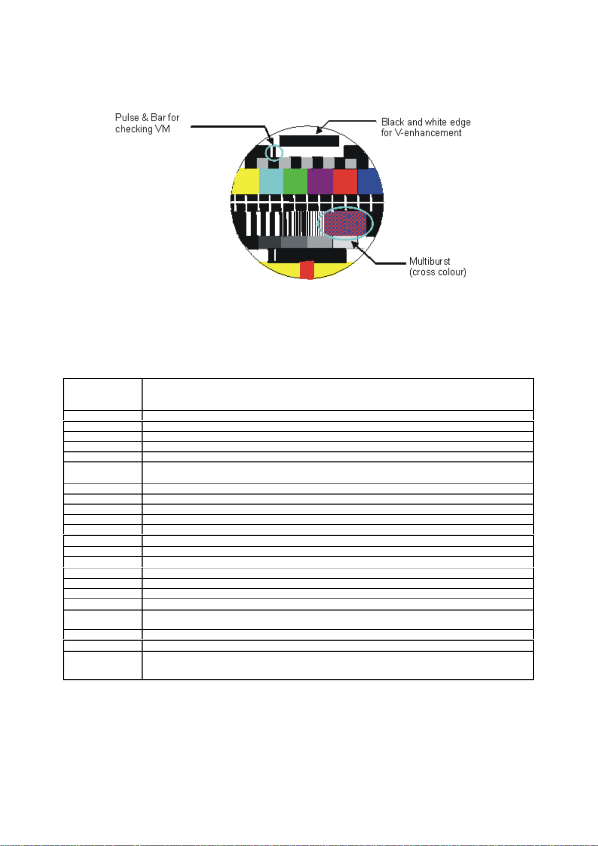
• Receive Philips circle test pattern. PICTURE»» MORE»»COMBFILTER by handset
• Ensure the combfilter is ON using handset and watch the multiburst making sure there is no 'Cross Colour'.
• Check "VERTICAL ENHANCEMENT" by watching horizontal edge of black and white.
• Check the total picture quality.
VM OPERATION CHECK
• Receive Philips circle pattern.
PICTURE»» MORE»» VM by handset
Check the bar width changes wider (see above ) when VM is switched ON by handset.
DTT MODULE FUNCTION CHECK LIST.
FUNCTION
Reception Lower
Channel (ch.21)
Video Output No error
RGB Output No error, right colour
Audio Output L/R out, No error
BER* under 7.00E-003
Reception Centre
Channel (ch.41)
Video Output No error
RGB Output No error, right colour
Audio Output L/R out, No error
BER* under 7.00E-003
Modem
RS232
Output from Module Indicate running software status correctly
Input to Module Possible to input command
PCMCIA
Software Upgrade
from PC Card
RF Output
OK STATUS
Possible to upgrade
Check the function of the RF output terminal for a gain of +2dB/-3dB.
Reduce the level of the digital test signal to -65dBm, there should be no blocking on screen. This test must
be performed with the +5V supply adjusted so that its voltage is set to the minimum, inside the tolerance i.e.
5.1V - 1% = 5.05 V.
OVER-LOAD PROTECTION CHECK.
• To check for tripping during maximum load for picture, set a signal generator to Black to White bounce signal.
10
Page 12
SHIPPING SPEC. TABLES
SERVICE DATA SETTINGS. This is the data set in SERVICE mode for various models.
Model No. Contrast Brightness Colour Sharpness More… Noise
1 C28W40TN(A) 100% 50% 50% 50% Off N/A Off On Normal Off
2 C32W30TN(A) 100% 50% 50% 50% Low N/A Off N/A Normal On
3 C32W35TN(A) 100% 50% 50% 50% Off Off Off Off Normal On
4 C32W40TN(A) 100% 50% 50% 50% Off N/A Off On Normal Off
5 C32W2000N 100% 50% 50% 50% Off Off Off Off Normal On
6 CL28W30TAN(A) 100% 50% 50% 50% Low N/A Off N/A Normal On
7 CL28W35TAN(A) 100% 50% 50% 50% Low Off Off Off Normal On
8 CL32W30TAN(A) 100% 50% 50% 50% Low N/A Off N/A Normal On
9 CL32W35TAN(A) 100% 50% 50% 50% Low Off Off Off Normal On
SERVICE DATA SETTINGS. This is the data set in SERVICE mode for various models.
Model No. Volume Loudness more Mode Graphic
1 C28W40TN(A) 10% Off 1 50% Pro Logic N/A Digital Auto
2 C32W30TN(A) 10% Off 1 50% N/A 100Hz Analogue Auto
3 C32W35TN(A) 10% Off 1 50% Pro Logic Progressive Analogue Auto
4 C32W40TN(A) 10% Off 1 50% Pro Logic N/A Digital Auto
5 C32W2000N 10% Off 1 50% Pro Logic Progressive Analogue Auto
6 CL28W30TAN(A) 10% Off 1 50% N/A 100Hz Analogue Auto
7 CL28W35TAN(A) 10% Off 1 50% Pro Logic Progressive Analogue Auto
8 CL32W30TAN(A) 10% Off 1 50% N/A 100Hz Analogue Auto
9 CL32W35TAN(A) 10% Off 1 50% Pro Logic Progressive Analogue Auto
SERVICE DATA SETTINGS. This is the data set in SERVICE mode for various models.
Model No. Sleep
Timer
1 C28W40TN(A) Off Panoramic Panoramic On English 100% Mid On Normal
2 C32W30TN(A) Off Panoramic Panoramic On English N/A N/A On N/A
3 C32W35TN(A) Off Panoramic Panoramic On English 100% Mid On Normal
4 C32W40TN(A) Off Panoramic Panoramic On English 100% Mid On Normal
5 C32W2000N Off Panoramic Panoramic On English 100% N/A On Phantom
6 CL28W30TAN(A) Off Panoramic Panoramic On English N/A N/A On N/A
7 CL28W35TAN(A) Off Panoramic Panoramic On English 100% Mid On Phantom
8 CL32W30TAN(A) Off Panoramic Panoramic On English N/A N/A On N/A
9 CL32W35TAN(A) Off Panoramic Panoramic On English 100% Mid On Phantom
Default
Zoom
Default
4:3
Equaliser
Auto Wide
Detection
Sound
Language Surround
100Hz/ Progressive
Mode
Reduction
Scan
Set-up
Comb
Filter
Digital/ Analogue
Seating
Internal
Position
CTI VM White
Mode
Speakers
Point
16:9 Mode
Channel
Centre
Black
Stretch
SERVICE DATA SETTINGS. This is the data set in SERVICE mode for various models.
Model No. AV1 VCR
1 C28W40TN(A) On Auto On RF Off Off I Off 11 76 Off
2 C32W30TN(A) On Auto Off RF Off Off I On 11 76 N/A
3 C32W35TN(A) On Auto Off RF Off Off I Off 11 76 Off
4 C32W40TN(A) On Auto On RF Off Off I Off 11 76 Off
5 C32W2000N On Auto On RF Off Off I Off 11 76 On
6 CL28W30TAN(A) On Auto Off RF Off On L/L’ On 11 76 N/A
7 CL28W35TAN(A) On Auto Off RF Off On L/L’ On 11 76 On
8 CL32W30TAN(A) On Auto Off RF Off On L/L’ On 11 76 N/A
9 CL32W35TAN(A) On Auto Off RF Off On L/L’ On 11 76 On
SERVICE DATA SETTINGS. This is the data set in SERVICE mode for various models.
Model No. RGB
1 C28W40TN(A) 35 31 32 4 4 83V 3 31 N/A Single
2 C32W30TN(A) 35 31 32 4 4 71V 3 31 N/A Single
* C32W35TN(A)
(Old FB/New FB)
4 C32W40TN(A) 35 31 32 4 4 83V 3 31 N/A Single
5 C32W2000N
(Old FB/New FB)
6 CL28W30TAN(A) 35 31 32 4 4 71V 3 31 16 Single
7* CL28W35TAN(A)
(Old FB/New FB)
8 CL32W30TAN(A) 35 31 32 4 4 71V 3 31 16 Single
9* CL32W35TAN(A)
(Old FB/New FB)
Mode
Shift
AV1 SAV
Mode
Text
Shift
35 31 32 4 4 62V/71V 3 31 N/A Single
35 31 32 4 4 62V/71V 3 31 N/A Single
35 31 32 4 4 62V/71V 3 31 6/16 Single
35 31 32 4 4 62V/71V 3 31 6/16 Single
AV2 VCR
Mode
R, G, B Cool
Offset
*AV2 Output
Mode
Warm
Offset
AV3 VCR
Mode
Cathode
Level
B/G Other VHF AFC Offset L’ Offset 3DS Mode
C Delay Text
Brightness
SECAM
Offset
Current Text
Mode
11
Page 13

SERVICE DATA SETTINGS. This is the data set in SERVICE mode for various models.
Model No. Top
1 C28W40TN(A) Off SGL JBL Off Off Off 1 50% 1 1
2 C32W30TN(A) Off SGL JBL Off Off Off 1 50% N/A 1
3 C32W35TN(A) Off SDS JBL Off Off On 1 50% N/A 1
4 C32W40TN(A) Off SGL JBL Off Off Off 1 50% 1 1
5 C32W2000N Off SDS JBL Off Off Off 1 50% N/A 1
6 CL28W30TAN(A) On SGL JBL Off Off On 1 50% N/A 1
7 CL28W35TAN(A) On SDS JBL Off Off On 1 50% N/A 1
8 CL32W30TAN(A) On SGL JBL Off Off On 1 50% N/A 1
9 CL32W35TAN(A) On SDS JBL Off Off On 1 50% N/A 1
Text
Text
Modes
Processor Tube
Type
M Gating Hotel
ModeNoStandby
Prog. Max.
Volume
DTT
Prog.
Unit
ID
12
Page 14
DIGITAL COMB FILTER – TOSHIBA TC9090AF.
The operation of a comb filter is to separate the composite video into luminance and reconstruct the chrominance colour sub carrier
signal using digital signal processing techniques. The comb filter IC, IN01 has an additional vertical edge enhancement feature.
Composite video input (Pin 6 of connector E500) and colour sub-carrier (pin 8 of E500) are converted via an 8 bit analogue to digital
converter where the vertical enhancement and digital comb filtering takes place. Separated luminance and chrominance output
components are available via a digital to analogue 8 bit converter at pins 1 & 4 respectively.
SCAN VELOCITY MODULATION.
During transmission the signal sufferers from degradation and also due to the frequency characteristics of the television circuitry.
This normally results in a gently rise or fall in the luminance change areas when black-to-white-to-black patterns are received.
The picture sharpness quality can be assessed by how steep the leading and trailing edges are. The scan velocity modulation circuit
has been designed to improve picture quality, i.e. make the video signal edges steeper, by controlling the horizontal scanning
velocity of the electron beam in the CRT.
The velocity modulation circuit produces a compensation signal by adding the RGB components then differentiating. The
compensation signal is given some current gain, applied to the auxiliary coil (connector E806) on the neck of the cathode ray tube
(CRT).
The VM circuit is located on the CRT base along with the final RGB amplifiers. The RGB signals derive from PL803 pins 4-6 and
into emitter of Q861, through the differentiator C863, R891 arriving at the base of Q862 for voltage amplification and latter stages,
power gain.
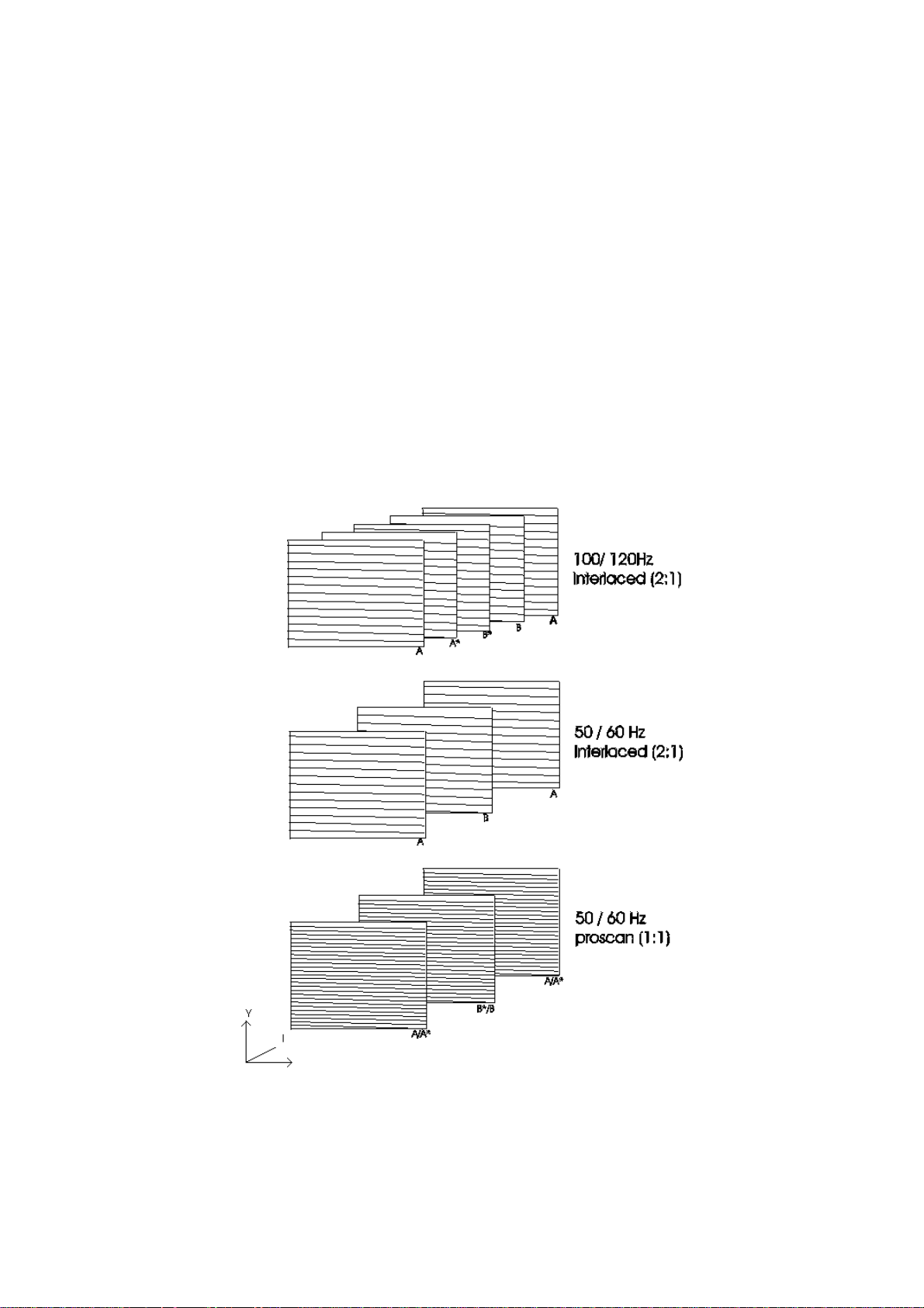
DIGITAL DOUBLE SCAN CONVERSION UNIT (FEATURE BOX).
The main feature of this unit is double scan frequency conversion, 100/120Hz interlaced and 50/60Hz progressive scan. Other
features of this unit are CTI (Colour Transient Improvement), horizontal compression, noise reduction, sharpness and vertical zoom.
These functions are controlled by I2C bus and are provided elsewhere by the picture improvement IC, TDA 9178 (IE01) for digital
models without 100Hz/progressive scan.
Scan rate conversion mode for display
13
Page 15

As the diagram shows, A/B are the Odd/Even original 50Hz signal fields which are used to create extra picture information, while
A*/B* are the predicted/manipulated extra picture information, created by the feature box. Fig.1 shows the differences between
100/120Hz interlaced and 50/60Hz progressive scan. The biggest advantage of progressive scan is "non-interlaced" scanning;
keeping the field frequency at 50/60Hz. This means the line construction is double per field, compared with 100/120Hz interlaced. It
will make very fine pitch scan lines and will eliminate line flicker. The advantage of selecting 100Hz operation will be the reduction of
large area flicker and will reduce the line flicker (except for A8 W30 100Hz models).
This unit is powered from +5V and +8V supplies, feeding into pins 21, 22 and 26 of E10 respectively. The three input 50Hz video
signals Y, U, V are sent to this unit at pins 8, 10 and 12 of E11. The Y, U, V video output signals (double frequency video) are taken
from pins 5, 3 and 1 of E11. The horizontal and vertical sync signals are input to this unit as a composite sync signal at 24 of E10,
the double frequency horizontal and vertical sync signals outputs are from pins 30 and 31of E10.
INPUT PROCESSOR - PHILIPS TDA 9320.
The TDA9320 is a multistandard input processor. Features include:
VIDEO OUTPUTS/EXTERNAL INPUTS.
The input processor has provision for three CVBS inputs (1 internal & 2 external) and 2 Y/C inputs. The external CVBS inputs are
used for the Scart sockets. The Y/C inputs are used for S-VHS and a third CVBS input. The circuit can detect whether CVBS or a
Y/C signal is presented to AV3 input. The I.C. has 2 RGB inputs with fast switching. The switching of the various sources is
controlled by I2C and detection of a Comb filter can be made.
SYNCHRONISATION.
The sync separator is preceded by a controlled amplifier which adjusts the sync pulse amplitude to a fixed level. These pulses are
fed to the slicing stage which is operating at 50% of the amplitude. The sync pulses are fed to the phase detector and to the
coincidence detector. This coincidence detector is used to detect whether the line oscillator is synchronised and can also be used
for transmitter identification. The PLL has a very high statical steepness so that the phase of the picture is independent of the line
frequency.
For the horizontal output pulse, two conditions are possible:
An HA pulse which has a phase and width which is identical to the incoming horizontal sync pulse.
A clamp pulse CLP which has a phase and width which is identical to the clamp pulse in the sandcastle pulse.
The HA/CLP signal is generated by means of an oscillator which is running at a frequency of 440 x FH. Its frequency is divided by
440 to lock the first loop to the incoming signal. The free running frequency of the oscillator is determined by a digital control circuit
which is locked to the reference signal of the colour decoder. When the coincidence detector indicates an out of lock situation the
calibration procedure is repeated.
The vertical pulse is obtained via a vertical count down circuit. The countdown circuit has various windows depending on the
incoming signal (50/60Hz).
VISION I.F. AMPLIFIER.
The video signal is demodulated by means of a PLL carrier regenerator. This circuit contains a frequency detector and a phase
detector. During acquisition the frequency detector will tune the VCO to the right frequency. After lock-in, the phase detector controls
the VCO so that a stable phase relation between VCO and the input signal is achieved. The VCO is running at double the I.F.
frequency with the reference signal for the demodulator obtained by means of a frequency divider circuit.
The AFC output is obtained by using the VCO control voltage of the PLL and can be read via the I2C bus. The AGC detector
operates on top sync and top white level. The time constant on the AGC system during positive modulation is long to avoid visible
variations of the signal amplitude. To improve the speed of the AGC system a circuit has been included which detects whether the
AGC detector is activated every frame period. When during 3 field periods no action is detected the speed of the system is
increased. For signals without peak white information the system switches automatically to a gated black level AGC. Because a
black level clamp pulse is required for this way of operation the circuit will only switch to black level AGC in the internal mode.
The circuit contains a video identification circuit which is independent of the synchronisation circuit. Therefore search tuning is
possible when the display section of the receiver is used as a monitor.
CHROMA & LUMA PROCESSING.
The I.C. contains a chrominance bandpass filter , the SECAM cloche and chrominance traps. The filters are calibrated using the
tuning frequency and the crystal frequency of the colour decoder. The luminance output signal which is derived from the incoming
CVBS or Y/C signal can be varied in amplitude by means of a separate gain control.
COLOUR DECODING.
The colour decoder can decode PAL, NTSC and SECAM signals. The PAL / NTSC decoder contains an alignment free crystal
oscillator with 4 separate pins, a killer circuit and two colour difference demodulators. The 90o phase shift for the reference signal is
made internally. Because it is possible to connect 4 different crystals to the colour decoder, all colour standards can be decoded
without external switching circuits. Crystals not used must be left open. The horizontal oscillator is calibrated by means of the crystal
frequency of the PLL.
The I.C. contains an automatic colour limiting circuit which is switchable which prevents over saturation when signals with a high
chroma-to-burst ratio are received. The acl circuit is designed such that it only reduces the chroma signal and not the burst. This has
the advantage that the colour sensitivity is not affected by this function.
The SECAM decoder contains an auto-calibrating PLL demodulator which has two references, the 4.43MHz sub-carrier frequency
which is obtained from the crystal oscillator which is used to tune the PLL to the desired free running frequency and the bandgap
reference to obtain the correct absolute value of the output signal. The VCO of the PLL is calibrated during each vertical blanking
period, when the I.C. is in search or SECAM mode. The base-band delay line is integrated into the package.
14
Page 16

PICTURE IMPROVEMENT - PHILIPS TDA 9178.
The picture improvement IC is an analogue video processor offering three main processing functions; luminance vector, colour
vector and spectral processing. Features presently being implemented are; luminance transient improvement (LTI), colour transient
improvement (CTI), variable gamma control and picture dependant non-linear Y and U, V processing by luminance histogram
analysis.
The spectral processor provides luminance transient improvement, luminance detail enhancement by smart peaking and colour step
improvement (CTI). The linewidth control may be user defined. The luminance vector processor, the transfer function is controlled in
a non-linear manor by histogram analysis of measured luminance values measured in a picture. As a result the contrast ratio of the
most important parts of the scene will be improved. A variable gamma function after the conversion offers the possibility of
alternative brightness control or factory adjustment of the picture tube.
The following functions sharpness, noise reduction and colour transient improvement (CTI) are provided by the picture improvement
IC for digital models, while 100Hz/progressive scan models provide these functions within the double scan module. All functions
described are switchable/adjustable via I2C control using the options in the service menu.
Y, U and V signals are taken from I200 pins 49, 50 & 51 and go straight into Yin Uin and Vin (pins 6, 8 and 9 of IE01). The enhanced
Y, U & V outputs originate from IE01 (pins 19, 17 & 16 respectively) and are directed to IE02 (pins 28, 27 & 26 respectively).
TUNER.
The tuner U100, is a frequency synthesis type with an unbalanced input, powered from the +5V rail while the tuning voltage is
supplied by the +33V rail, supplied from the horizontal deflection circuit. Direct frequency access, channel selection, AGC and AFC
functions are controlled via the I2C bus. AGC, AFC and Offset controls may be selected by entering the service menu and selecting
the ‘tuner’ option.
Pin 1, AGC is taken from pin 62 of TDA 9320. The balanced I.F. output is taken from pins 10 & 11, which are then arrive at both the
inputs of the vision and sound SAW filters (pins 1 & 2). The outputs from X200 and X202 (pins 4 & 5 respectively) pass through to
pins 2 & 3 and pins 63 & 64 of I200, where they are demodulated.
RGB PROCESSOR - TDA 9330.
VERTICAL DEFLECTION & GEOMETRY CONTROLS.
The drive circuit for the vertical and E-W deflection circuits are generated by means of a vertical divider which gets its clock from the
line oscillator. The divider is synchronised by the incoming vertical pulse, generated by the input processor or the feature box.
The vertical drive is realised by means of a differential output current. The outputs must be DC coupled to the vertical output stage.
The vertical geometry can be adjusted by I2C control via the service menu.
HORIZONTAL SYNCHRONISATION & DRIVE CIRCUIT.
The horizontal drive signal is obtained from an internal VCO which is running at a frequency of 13.75MHz. This oscillator is
stabilised to this frequency by means of a resonant oscillator 12 MHz. The internal VCO is synchronised to the incoming horizontal
Hd pulse by means of a PLL with an internal time constant. The horizontal drive signal generated by means of a second control loop
which compares the phase of the reference signal from the internal VCO with the flyblack pulse. The time constant loop is internal.
The I.C. has a dynamic horizontal phase correction input which can be used to compensate phase shifts which are caused by beam
current variations. Additional settings of the horizontal deflection which are realised via the second loop are the horizontal shift and
the parallelogram correction.
The horizontal drive signal is switched on and off via the so called soft-start/soft-stop procedure. This function is realised by means
of a variation to the Ton of the horizontal drive pulse. For EHT generators without bleeder the I.C. can be set in a fixed beam current
mode. In that case the picture tube capacitance is discharged with a current of about 1mA which is determined by the black current
feedback loop. With the fixed beam current option activated it is still possible to have a black screen during switch-off. This can be
realised by placing the vertical deflection in an overscan position.
An additional function of the I.C. is the low-power start-up feature. This mode is activated when a supply voltage of 5V is supplied to
the start-up pin. The required current for this function is 3mA typical. In this condition the horizontal drive signal has the normal T
and Ton grows gradually from zero to about 30% of the normal value. This results in a line frequency of about 50kHz or 25kHz. The
output signal remains unchanged until the mains voltage is switched-on. Then the horizontal drive signal will gradually change to the
normal frequency and duty cycle via the soft-start procedure.
The I.C. has a general purpose bus controlled DAC output with a resolution of 6 bits and with an output voltage range between 0.2
to 4V.
off
INPUT SIGNALS.
The RGB control circuit of the TDA 9330 contains three sets of input signals.
Y, U, V, input signals which are supplied by the input processor or feature box. The nominal input signals for u and V are 1.33 V
and 1.05V
to-Peak
Two RGB sources are intended for use by the Scart, while the second is used for the OSD and teletext. The required input signal
has an amplitude of 0.7V
. this input is only controlled by brightness.
Switching between various sources can be realised via the I2C bus and by fast insertion switches. The circuit contains switchable
matrix circuits for the colour difference signal so that the colour reproduction can be adapted for PAL/SCAM and NTSC.
Peak-to-Peak
respectively. These input signals are controlled by brightness, contrast and saturation.
Peak-to-Peak
. The switching between the internal signal and the OSD signal can be realised via a fast blanking
Peak-
OUTPUT AMPLIFIER.
The output signal has an amplitude of around 2V black-to-white at nominal settings. The required white point setting of the picture
tube is implemented by 3 separate gain settings for the RGB channels.
15
Page 17

To obtain an accurate biasing of the tube, a continuous cathode calibration circuit is implemented by means of a two point black
level stabilisation circuit. By inserting 2 test levels for each gun and comparing the resulting cathode currents with two different
reference currents the influence of the picture tube parameters like the spread in cut-off voltage can be eliminated.
SIGNAL PATH DESCRIPTION.
The I.F. signal is obtained from SAW filters X200 (vision) and X202 (Sound ) pins 4 & 5 and are fed into pins 2 & 3 vision and 63 &
64 sound of I200. A composite video signal is available at pin 10 from the vision demodulator. I.F. sound out from pin 6. The video is
taken from pin 10 via C304 into pin 12 and out at pin 13. This is the selectable Group Delay via software input output. The
composite video gets taken through buffer and filtering stages where the desired video returns to I200 at pin 14.
The AV switching matrix supports two Scart sockets, phono CVBS and S-VHS inputs. Scart CVBS inputs are at pins 20 (AV1 E301)
and 16 (AV2 E302), CVBS outputs to Scart pins 19 from emitter of Q301 (AV1) and emitter of Q303 (AV2). The RGB input (Digital
models) to I200 from the Digital Terrestrial Tuner (DTT) comes to pins 36-38, from P301 pins 9, 7 and 5, respectively. S-VHS input
is via E300 to pin 23 & 24 of IE02, detection of CVBS input is detected within IE02. For models with progressive scan feature
detection for a Comb filter has been fitted via Y/C input pins 28 & 29. Colour sub-carrier output for the Comb filter is form pin 30.
Y, U and V signals are taken from I200 pins 49, 50 & 51 and go straight into Yin Uin and Vin (pins 6, 8 and 9 of IE01) for 50Hz
operation, while 100Hz operation, Y, U, V signals are directed to pins 9, 10 & 12 of the double scan module (UQ01).
Other miscellaneous pins such as the sandcastle pin 59 is independent of the sandcastle pulse generated by IE02, they do not drive
each other. The Vertical and Horizontal output pulses generated by I200 drive the double scan module, pins 18 & 19 respectively
(100Hz operation) or the IE02 (50Hz operation) pins 23 & 24. I2C control lines are pins 46 & 47, and tuner AGC control voltage is
present at pin 62.
As already previously described Y, U, V signals in either 50Hz/100Hz/Progressive scan mode are sent to pins 26-28 of the TDA
9330 (IE02). Once inside the RGB processor, geometry and synchronisation functions can be implemented before being sent to the
CRT base (pins 40-42 of IE02 & 3-5 of P302) for final video amplification and to the velocity modulation circuit.
The vertical drive output is provided by pin 1 & 2 of IE02 directly to I601 Vertical Output I.C. (pins 11 & 12). Horizontal output is from
pin 8 of IE02 and feeds the base of Q701 Bipolar (50Hz), Q701B MOSFET (100Hz). East-West drive output can be obtained at pin 3
and is driving the gate of the East-West MOSFET Q700.
I2C is present at pins 10 & 11 (IE02) and +8V supply rails at pins 7 & 17. Two sets of RGB inputs are available, only one set is used
for the OSD, pins 35-37, the other is for a VGA board which is not fitted.
AUDIO CIRCUIT
The output from the Tuner T1 is fed via a gain and buffer stage formed by Q200 and Q201 to the Saw Filter X202. The saw filter has
two separate characteristics depending on which of the two inputs (on pin 1 and 2 of the Saw Filter) the signal is applied to.
Selection is achieved by the combination of Q204 and Q203. For most standards, pin 1 is selected. However, when an L’ Signal has
been selected , the micro ( I001) instructs I200 via an I2C command to take pin 19 high. When this happens Q204 conducts taking
pin 1low and switching Q203 and D203 off. This means that the collector of Q203 goes high allowing D202 to conduct and hence
the signal to be applied to pin 2. To return to other broadcast standards, pin 19 of I200 is obviously returned to the low condition.
The output of the Saw is applied to pins 63 and 64 of I200. Here the Signal is transformed from the 1st IF (30 – 40 MHz depending
on transmission standard) to the sound IF (5.5 to 6.5 MHz depending on the transmission standard ).
I200 also provides AM demodulation for the L’ and L standards. The demodulated signal appears superimposed on the Sound IF on
pin 5 of I200.
This signal then takes two paths. The first takes it through a Low pass filter formed by R426 and C427 and coupling capacitor C426.
This is then applied to pin 55 of I400 and forms the AM sound Input. The second path takes the signal through a amplifier and buffer
stage formed by Q400 and Q401.
After these stages some high pass filtering is applied by C464 and R477 before the sound IF is applied to pin 60 of I400 via C431.
I400 is The MSP3410D. This IC provides Nicam , FM Mono and FM Stereo Demodulation as well as matrixing of the scart / digital
receiver signals (If Fitted).
The AV1 input is applied on pins 52 and 53, the AV2 input on pins 49 and 50, the AV3 input on pins 46 and 47. The Digital input
(DTT) is applied to pins 43 and 44 (when fitted). In Each case a 100R resistor and 330n capacitor is used.
The Scart outputs on I400 use the following protocol.
Scart Output
AV1 RF Digital
AV2 Selectable or Auto* Selectable or Auto*
*If auto is selected in the on screen menu’s, AV2 follows the audio of what is being watched the device is I2C Controlled via pins 10
and 11 and receives a reset from the micro at power up on pin 24.The clock is provided by X406 on pins 62 and 63. The device has
three supply rails, 5V Digital (Pin 18), 5v Analogue (Pin 57), and 8v Analogue (Pin 39).
Non Digital Models Digital Models
Output Signal
16
Page 18

AUDIO OUTPUT
The left, right, centre and surround signals are output from pins 29, 28 26 and 25 of the MSP3410D (I400) and are then applied to
an operational amplifier (IF03) at pins 5, 10, 12 and 3 respectively. This adds 3dB of gain.
The outputs from IF03 for the left and right (pins 7 and 8) are supplied to both the audio amplifier (I401) via the attenuation networks
R443 / R439 & R446 / R447 and the phono outputs via buffer transistors QF02 and QF01.
The centre and surround outputs from IF03 (pins 14 and 1) are only supplied to the phono outputs via buffer transistors QF22 and
QF21.
The left and right output stage consists of one TDA7297 (I401) which is a dual bridge amplifier which in this case is driven to give
12W per channel @ 10% thd. The power output is limited by the Vcc supply to pins 3 & 13.
The left and right signals are input to pins 4 & 6 and the outputs obtained from pins 1& 2 and 14 & 15.
Warning. Neither output for either channel is connected to the chassis ground so caution must be taken if an oscilloscope and
other mains operated equipment with a common earth is to be used simultaneously when checking the audio outputs.
The TDA7297 has two control lines on pins 6 & 7. These control inputs are high when the outputs are active and low when muted.
The outputs from pins 2 and 14 of I401 are connected directly to pins 2 and 3 of P400. The outputs from pins 1 and 15 are
connected to pins 1 and 4 of P400 via the headphone socket J400. When a set of headphones is inserted the connections between
I401 and P400 are broken. The left and right outputs from pins 1 and 15 of I401are connected to ground via C438 / R438 & the left
headphone coil and C437 / R437 & the right headphone coil respectively. This method was used to limit the power dissipated in the
headphones.
J400 also contains a switch for the 16V supply that appears at the rear single phono socket. When a suitable plug is inserted into
the headphone socket the connection between pins 8 and 9 of J400 is broken removing the 16V from pin 8. This is sensed by pin 19
of I001 (the micro processor) via the potential divider R473 and R474, this tells I001 to change the audio menu’s to the headphone
versions (Dolby models only).
The 16V is also removed from the rear phono socket, this turns off the infra red surround sound speaker transmitter or the power
console (if connected - not supplied with all models).
For non Dolby models the speaker leads are connected directly to P400. For Dolby models the internal speakers are connected
from P400 via a sub panel screwed to the rear of the chassis frame. This houses two din type speaker sockets with internal
switches. The switches disconnect the internal left and right speakers when a plug is inserted, thus allowing external left and right
speakers to be fitted.
DOLBY DECODER.
The Dolby decoding is provided by IF01 (YSS241) The signals which are sent to this device from I400 in the I2S format, and are:SD0 (Pin Of I400) - the Left and Right channel data (before Dolby decoding)
SCK (Pin Of I400) - the system or bit clock
WS (Pin Of I400) - the word select line, provides selection between the Left and Right samples on the SDO Line.
IFO1 is provided with an 18.432 MHz clock via pin 1 of I400 (SYSCLK),a reset line from pin 4, and is I2C controlled. The Pro-logic
signals that the device decodes are provided in I2S form at pins 40 and 41 (DACS1 and DALR) These signals are in a 32bit per
channel format ( The MSP4310D uses 16 bit) and must therefore pass through a conversion IC IF02. This IC also takes a Bit clock,
DABC from pin 36 of IF01. IF02 then provides the 16 bit pro-logic I2S channels as SDI1 and SDI2 on pins 14 and 20 of I400.
I400 then passes these signals through DAC’s so that the Left, Right, Centre and Surround signals appear at pins 29, 28,26 and 25
as Pre-L, Pre-R, Pre-C and Pre-S respectively. Theses are then amplified by 3dB by op-amp IF03 to become AmpL, AmpR, Centre
and Surround. These then pass through a buffer and filter network to the four way phono plug JF01. The AmpL and AmpR signals
split off before the buffers to the amplifier I401 via dividing resistors R443/R439 and R446/R447 and are decoupled by C443 and
C445. The operation of the amplifier is explained elsewhere in this manual.
DEFLECTION
100HZ HORIZONTAL DEFLECTION STAGE (A8)
The 2H output from UQ01 (the feature box) from pin 30 is fed via K66 and RH03 to pin 24 of IE02 TDA9330 the "HOP".
The horizontal drive is then output from pin 8 is passed through an emitter follower stage (Q705) to the gate of Q701B. A mosfet is
used to sharpen the switching edges and reduce the temperature of the power transistor Q751. The drain of Q701B is fed from the
+B via R701 and the primary of the drive transformer T702. The secondary of the transformer drives the base of the power transistor
Q751, the collector of which is supplied from the +B via R751, L700 and the primary of the FBT T701. The emitter is connected to
ground via R760 a 1 Ohm 10W resistor ( R760 should be kept away from Q751 heatsink to reduce heat transfer) which is a sense
resistor for the protection circuit.
The capacitive divider network C717 and C708 produce a line pulse which is sampled by Z704 and clamped by D713 and D714 this
is then returned to pin 13 of IE02.
50HZ HORIZONTAL DEFLECTION STAGE (D8)
The HA OUT from pin 60 of I200 TDA9320 the "HIP" is fed via K66 and RH03 to pin 24 of IE02 TDA9330 the "HOP".
The horizontal drive is then output from pin 8 is fed to the base of Q701. The collector of Q701 is supplied from the +B via R701 and
the primary of the drive transformer T702. The secondary of T702 drives the base of the power transistor Q751. The collector of
Q751 is supplied from the +B via R751, L700 and the primary of the FBT T701. The emitter is connected to ground via R760 which
is a sense resistor for the protection circuit.
The capacitive divider network C717 and C708 produce a line pulse which is sampled by Z704 and clamped by D713 and D714 this
is then returned to pin 13 of IE02.
17
Page 19

VERTICAL DEFLECTION
On the 50Hz D8 the vertical drive pulse come from pin 61 (VA OUT) of I200 and on the 100Hz A8 it comes from pin 31 of UQ01.
This is fed via K65 and RV02 to pin 23 of IE02. The vertical sawtooth waveforms are output from pins 1 and 2 of IE02 and fed to
pins 11 and 12 of I601 via RV04 and RV03. I601 (TDA8354) is the vertical output amplifier, it requires 2 supply voltages,
approximately 14V to pins 4 and 10 to operate the IC and approximately 48V to pin 7 for the flyback pulse generator. The outputs
are from pins 2 and 9 with the gain setting feedback resistors R602 and R603 connected to pin 5.
Pin 1 is the vertical guard which is connected to pin 9 of IE02 if a vertical failure is detected the vertical part of the sandcastle pulse
is removed and IE02 blanks the picture to prevent damage to the tube. Z615 samples the flyback pulse which is then clamped by
Z606 this generates the frame pulse used by the micro I001.
EAST WEST CORRECTION
The east west parabola is output from pin 3 of IE02 and fed to the gate of Q700 via RH04. The drain of Q700 is connected to the
centre of the diode modulator D706 and D707 via the east west injection coil L751.
HIGH END FEATURE BOX
LOW END FEATURE BOX
18
Page 20

MICROCONTROLLER SECTION ON THE A8/D8 CHASSIS
INTRODUCTION:
The main microcontroller on the A8/D8 chassis is located at I001 (ST92R195B). This is an 80-pin QFP (quad-flat package) that is
surface mounted for compactness. This highly complex device controls many of the other integrated circuits via dedicated
input/output lines or the I2C bus. This device also generates the RGB signals for the on-screen display (OSD) menus and the
teletext. The device can acquire, decode and display the teletext without the need for a separate IC. This microcontroller is ROMless which results in the need of a separate memory device to store the program code necessary for operating the television. This
memory device is located at I002 and is multi-time programmable (MTP). This allows the device to be re-programmed and in the
future can even be re-programmed in the board without having to remove the back cabinet of the TV. The television stores all the
necessary customer preferences and operating settings in an on-board EEPROM (E2). This device can hold 2Kb of information for
storing the programme information (frequency, name, AV setting, etc.), factory alignment settings (geometry, white balance, tuner
AFC/AGC, etc.), service diagnostic errors and customer control settings (volume, brightness, contrast, etc.). This device
communicates with the main microcontroller via the I2C bus, even in the standby mode.
MAIN MICROCONTROLLER (I001)
INTRODUCTION
The ST92R195B is an enhanced microcontroller based on the ST9+ instruction set from STMicroelectronics. It is capable of
displaying menus and teletext for 50Hz and 100Hz televisions. This device can acquire/decode and display pages of teletext
information in FLOF (FastText) and TOP (only in Germany/Switzerland/Austria) modes. The device operates from a single 4MHz
crystal and a +5V supply. Dedicated address/data lines enable it to access 4Mbytes of address space, even though in this television
it is accessing 128Kbytes (1Mbit). These address/data lines are connected to the EPROM/MTP device which holds the instructions
necessary for controlling the television.
DESCRIPTION
EXTERNAL MEMORY INTERFACE MMU ADDRESS LINES
• Pins 1 (MMU0), 15 (MMU1) and 16 (MMU2) are used to access addresses above 64Kbytes. Normally pins 15 and 16 are
not used when using a 128Kbyte EPROM/MTP device (MX26C1000APC) in position I002.
• Pin 2 (MMU3) is used to select between either the EPROM/MTP in position I002, or a future device that can be fitted in
position I003. When this line is low, the MX26C1000APC device in position I002 is enabled (chip enable).
• Pin 17 (MMU4) is used as an output port to derive a clock signal needed for shifting the data into the 74HC595 shift
register (I006).
• Pin 18 (MMU5) is not used.
EXTERNAL MEMORY INTERFACE CONTROL LINES
• Pin 4 is the Data strobe line which is connected to the output enable input of the EPROM/MTP (I002). When data is read
from the EPROM/MTP, this line is temporarily low.
• Pin 8 is the Read/Write line for I003. Normally, this line is not used (HIGH) but if an SRAM were to be fitted into this
position, the line could be low when writing data to the SRAM.
EXTERNAL MEMORY INTERFACE ADDRESS LINES
• Pins 3, 5, 6, 7, 13, 14 and 71 to 80 are the address lines needed to specify which location in a 64Kbyte page is needed to
be accessed from the EPROM/MTP (I002). These lines are also connected to I003 if an SRAM is to be fitted in future.
Normally these lines will be changing state (0V to approx. +5V). By placing an oscilloscope on pin 12 of the EPROM/MTP
(I002) it can be confirmed that the microcontroller is operating successfully. In this case, this line should be changing state
very frequently.
EXTERNAL MEMORY INTERFACE DATA LINES
• Pins 63 to 70 are the 8 data lines needed for receiving data from the EPROM/MTP (I002). If an SRAM were to be fitted in
position I003, then these lines would be used to transfer data from the microcontroller to the SRAM. Under normal
circumstances these lines change from LOW (0V) to HIGH (approx. +5V).
GROUND CONNECTIONS
• Pin 9 (GNDM) is the ground connection (0V) for the external memory interface. This should be free of noise to enable
successful communications between the microcontroller and the EPROM/MTP (or SRAM).
• Pin 35 (GND) is the digital ground connection (0V) for normal operation of the device.
• Pin 62 (GNDA) is the analogue ground connection for the DAC and phase lock loops (PLL’s).
SUPPLY CONNECTIONS
• Pin 10 (VDDM) is the +5V supply for the external memory interface. Without this supply, the microcontroller cannot
communicate with the EPROM/MTP (or SRAM).
• Pin 34 (VDD) is the main digital supply voltage to the IC (5V 10% tolerance).
• Pin 52 (VDDA) is the analogue supply voltage for the DAC’s and PLL’s (+5V). These connections are all joined together
to the +5V standby rail of the television, ensuring that the microcontroller operates even in the standby state.
19
Page 21

CRYSTAL OSCILLATOR CONNECTIONS
• Pin 11 is the 4MHz crystal oscillator input (OSCIN).
• Pin 12 is the 4MHz crystal oscillator output (OSCOUT). By connecting a x100 scope probe to pin 11, it can be seen if a
4MHz sine wave is present at the oscillator input to the microcontroller.
RESET CONNECTION
• Pin 54 is the active low RESET input of the microcontroller. This input is normally high (approx. +5V) under operating
conditions, but changes state when the standby +5V power supply is typically below +4.5V. In this circumstance, the reset
IC (I021) pulls pin 54 low until the input of it is above +4.5V. The diode (D001) ensures that the capacitor (C015)
discharges quickly when the standby supply falls, so that the reset operates quickly. The capacitor (C015) charges up
slowly when the standby +5V supply is restored, ensuring that there is some hysteresis.
INFRA-RED (IR) RECEIVER INPUT
• Pin 25 is the IR receiver’s filtered output. This input from the IR receiver consists of PWM pulses between 0V and +5V
which are decoded by the microcontroller into useful commands from the handset. When a valid command has been
decoded, the Red LED on the front of the TV will briefly flash.
HORIZONTAL AND VERTICAL SYNCHRONISATION CONNECTIONS
• Pin 48 is the vertical synchronisation input from the deflection stage. This input is used to ensure that the OSD is
displayed in a stable vertical position. When the TV is in the standby state, this input is normally low. The vertical input is
triggered on the rising edge (positive polarity).
• Pin 9 is the horizontal synchronisation input from the deflection stage. This input ensures that the OSD is displayed in
stable horizontal position. When the TV is in the standby state, this input is normally low. This input is rising edge
triggered (positive polarity).
GENERAL INPUT CONNECTIONS
HEADPHONE INPUT
• Pin 19 is used to detect if the headphone has been inserted into its socket. This input is normally HIGH (+5V) unless the
headphone has been inserted, in which case it is near 0V. When the headphone is inserted, the headphone mode option
is then available in the "Sound Mode" Menu and the loudspeakers (and internal sub-woofer if available) in the television
are muted.
PROTECTION INPUT
• Pin 26 is used to determine if a protection fault has occurred on the chassis. This line is connected to the comparator
outputs 1, 13 and 14 of I903 in the power supply. This line is normally high (approx. +5V) unless a fault has occurred, in
which case it is near ground potential (0V).
• Comparator output 1 monitors the +16V audio supply rail for over-current. If this rail is shorted, or draws too much current,
then the comparator output (pin 1 of I903) will change state to 0V.
• Comparator output 13 monitors the EHT voltage generated by the FBT in the deflection circuit. If this voltage is too high,
then this output will be low to indicate that there is a problem with the deflection.
• Comparator output 14 is connected to the secondary side of the deflection’s line input transformer. It is primarily used to
indicate whether too much current is being drawn from the line-input transformer and FBT.
POWER-GOOD INPUT
• Pin 27 is used to indicate if the power has been removed from the TV or whether a static discharge has occurred. This
input is interrupt driven to react instantaneously to a falling edge (+5V -> 0V). Under this circumstance, the audio power
amplifiers are muted and the television begins to power-down into standby. This input is derived from the comparator
output (pin 2 of I903) in the power supply. This comparator provides an "early warning" indication that the primary supply
has been removed or a static discharge event has occurred. Under a static-discharge condition, the TV will enter the
standby condition temporarily before powering back up a few seconds later.
DTT FAN FAIL INPUT
• Pin 32 is used only on a D8 chassis fitted with a DTT module. It is used to indicate if a fault with the fan on the DTT unit
has occurred (e.g. fan stuck). This input is normally HIGH (approx. +5V) unless a fault condition has been detected (0V).
FRONT PANEL BUTTONS AND SAV3 SOCKET INPUTS
• Pins 36 and 38 are 2 of the 4 ADC inputs of the microcontroller.
• Pin 36 is connected to the Volume +/- buttons and the SAV3 (Hi-8) socket on the front panel of the TV. When the voltage
on this pin is changed to a value in a certain window, the microcontroller will interpret it as either a volume +, volume -,
volume +/- command and/or an SVHS Hi-8 connector was inserted into the Hi-8 socket.
• Pin 38 is connected to the Programme +/- and Menu buttons on the front panel of the TV. When the voltage on this pin is
changed to a value in a certain window, the microcontroller will interpret it as either a programme change or the menu
button was pressed.
20
Page 22

GENERAL OUTPUT CONNECTIONS
74HC595 SHIFT REGISTER OUTPUTS
STORAGE-REGISTER CLOCK OUTPUT (RCLK)
• Pin 20 of the microcontroller is connected to the rising edge (positive triggered) input (pin 12) of I006. This line is normally
low when not communicating with the device or when shifting data into it. Once the full 8-bits have been shifted in, the
RCLK line rises in order to latch the data to the device’s outputs.
SHIFT-REGISTER CLOCK OUTPUT (SCLK)
• Pin 17 of the microcontroller (MMU4) is used to transfer the data into to the 8-stage shift-register on the rising edge of the
SHIFT-REGISTER DATA OUTPUT (SI)
EEPROM WRITE ENABLE OUTPUT
ON/OFF OUTPUT
ON/OFF 2 OUTPUT
SCLK. 8 clock pulses are needed to transfer 8 bits of data into the shift register.
• Pin 21 of the microcontroller is used as the data line input to pin 14 of the shift register. When this line is HIGH, and the
SCLK changes from low to high, the first bit of data (logical 1) is shifted into the register. When this input is low, the first bit
of data is ‘0’, on the rising edge of the SCLK.
• Pin 22 is the E2 write enable output line, which is connected to pin 7 of the EEPROM (E2). When this output is HIGH
(approx. +5V), the E2 cannot be written to (write disable) but data from the device can be read. When this output is low
(0V), then data can be written to the E2. This hardware line helps to protect the E2 from inadvertent write operations,
which could occur under abnormal circumstances.
• Pin 28 is the On/Off line which turns On (LOW) /Off (HIGH) the secondary supplies (+B, +16V audio rail, +8V and +5V).
The standby +5V and+10V rails are unaffected when this output is HIGH (TV in the standby state). Under normal
operating conditions, this output will be low when the TV is NOT in the standby condition.
• Pin 29 is the On/Off 2 line which turns On (LOW) / Off (HIGH) the DTT/ASW sub-power supply.
DTT RESET OUTPUT
• Pin 31 is the DTT reset line which is asserted HIGH (+5V) on power-up and shutdown of the DTT module. Under normal
operating conditions when the TV is powered up, this line is low.
I2C DISABLE OUTPUT
• Pin 33 is the I2C disable output which prevents the main chassis I2C bus from being connected to the I2C bus of the
microcontroller (I001) and E2 (I002). This line is normally HIGH when the TV is in the standby state. This output is
inverted using the 74HC04 hex inverter IC (I004) and in connected to pins 5 and 6 of I007. In the standby condition, pins 5
and 6 of I007 (74HC4066) are low and the M.SDA and M.SCL (microcontroller) lines are disconnected from the SDA and
SCL (main chassis) I2C lines. When writing to the E2, the I2C disable output is also pulled high, to ensure that successful
writing of the data has occurred (e.g. to log fault diagnostics when the TV fails to power-up and the main chassis I2C bus
is low).
SCART DISABLE OUTPUT
• Pin 39 is used to disable the RS232 transmit and receive lines from pins 10 (Rx) and 12(Tx) of scart socket 2. This is
necessary when the TV is functioning normally. However, when the TV is in service or diagnose modes, then this output
will be low to enable connection of the RS232 lines of the microcontroller to the scart socket.
MUTE OUTPUT
• Pin 40 is the mute output for the on-board audio amplifiers. This output is HIGH when the amplifiers are in the mute
condition (e.g. Standby). If the user has chosen to use the internal speakers, then under normal operating conditions, this
output will be LOW. When powering down, this output will quickly rise to mute the speakers, to prevent any unwanted
‘popping’ noises from being heard.
GREEN LED OUTPUT
• Pin 41 is the green LED output, which is only used on the D8 chassis fitted with a DTT module. This output is high when
the green led is ON. When the DTT module is in the partial standby state or when recording a digital terrestrial
programme, then this LED will be ON and will be mixed with the red LED to produce an amber colour. When the DTT
module is connected via the telephone line and receives mail, then this LED will flash periodically to indicate this
condition.
• When the TV first has power applied to it, then the green LED will be ON. Soon after, though, this LED should extinguish
to indicate that the TV is operating correctly. NOTE: This is one of the easiest ways to check that the microcontroller is
running the programme code correctly in the EPROM/MTP. If the green led remains ON, then the microcontroller or
EPROM/MTP has a fault preventing the code from being executed correctly.
21
Page 23

RED LED OUTPUT
• Pin 42 is the red LED output, which is used to indicate the standby state and when an IR command has been successfully
received and decoded. When the TV is in the standby state, this output will be HIGH to ensure that the red LED is brightly
lit. When the TV is not in standby, then this output will be low, but the red LED will remain dimly lit through resistor R081.
When an IR command has been successfully received, then the LED will flash briefly, to inform the user that the button on
the handset was pressed correctly.
I2C CONNECTIONS
• Pin 23 is the I2C bus data input/output for transferring data between other I2C peripherals/devices. This line is only
connected to the EEPROM (I005) when in the standby state or when writing to the EEPROM. This line is constantly active
when the TV is powered up and normally changes state between (+5V and 0V).
• Pin 24 is the I2C bus clock output for clocking the data to other I2C peripherals/devices. The clock line is also
disconnected from the main chassis when in the standby state or when writing to the EEPROM. This line oscillates at a
frequency around 90KHz
RS232 CONNECTIONS
• Pin 30 is the RS232 Transmit line from the microcontroller. It can be routed to pin 12 of the scart socket and to pin 3 of
connector P001 for the DTT module (only on D8 chassis). This line is time shared between communicating with the DTT
unit and the scart socket (for diagnostics). When the DTT disable line is LOW, the TXD line is routed from pin 1 to pin 2 of
I008 (74HC4066). When the Scart disable output from the microcontroller (pin 39) is low, then the TXD can be routed from
pin 1 to pin 2 of I007 (74HC4066). There is never a situation whereby both disable outputs are low (enabling both DTT
and SCART RS232 communications).
• Pin 37 is the RS232 Receive line for the microcontroller. It can be routed from Scart 2 RXD (pin 10) and from pin 4 of
connector P001 for the DTT unit (only on D8 chassis). When the DTT disable line is low, the DTT can transmit to pin 10 of
I008 and is then routed through to Pin 37 of the microcontroller. When the Scart disable line is low, then the data can be
routed from pin 10 of scart 2 to pin 10 of I007 and then through to pin 37 of the microcontroller. There is never a situation
when both RS232 enable lines are HIGH (disable outputs LOW).
RGB CONNECTIONS
• Pin 44 is the OSD/Teletext RGB blanking signal necessary for allowing insertion of the OSD/Teletext onto the picture.
When this output is high (approx. +5v), then the RGB signal will be superimposed onto the current picture.
• Pin 45 is the OSD blue signal necessary for displaying BLUE colours for the OSD and Teletext.
• Pin 46 is the OSD green signal necessary for displaying GREEN colours for the OSD and Teletext.
• Pin 47 is the OSD red signal necessary for displaying RED colours for the OSD and Teletext.
CVBS CONNECTIONS
• Pin 60 is the Composite Video signal input for VPS and WSS slicing. It is normally AC coupled and internally clamped to
ensure reliable operation. VPS (video programming system) is necessary when auto-sorting programmes in
Germany/Austria/Switzerland. WSS (wide-screen signalling) is used to indicate the aspect ratio of the incoming signal.
The TV can then use this information to display the picture in the correct format.
• Pin 61 is the Composite Video signal input for Teletext acquisition and decoding and also for sync extraction, necessary
for obtaining the correct line timings for slicing the teletext information and VPS/WSS information.
EPROM/MTP (I002)
INTRODUCTION
The device located in position I002 is used to store the program code needed by the microcontroller to operate the television
correctly. This 32 pin device is an MTP (multi-time programmable memory) which allows for it to be re-programmed out of the
chassis without having to erase it using conventional UV EPROM erasers. The device currently used on the A8/D8 chassis is the
MX26C1000APC, which can hold 128Kbytes of information (1Mbit). This device also holds any initialisation data to be downloaded
to an EEPROM. When a blank EEPROM is fitted, the initialisation data is automatically downloaded to it when power is applied to
the chassis.
DISCUSSION
SUPPLY/GROUND CONNECTIONS
• Pins 32 and 16 are the +5V supply and ground connections respectively. The supply voltage of +5V is always present
even when the TV is in the standby state.
ADDRESS CONNECTIONS
• Pins 2 to 12, 23 and 25 to 29 are the 17 address lines needed to access the full 128Kbytes of 8-bit data inside the device.
These lines are connected directly with the microcontroller so that it can request data from the MTP when operating. An
oscilloscope can be used to check pin 12 of the MTP to check whether the microcontroller is running correctly and
accessing the MTP. This pin should be oscillating at a frequency of around 2MHz and is a non-periodic square waveform.
DATA CONNECTIONS
• Pins 13 to 15 and 17 to 21 are the 8 data lines needed to transmit a byte at a time to the microcontroller. These outputs
are normally tri-state and are high-impedance when the output enable pin 24 of the MTP is HIGH. When the output enable
pin is low, the data from the required address will be output on these pins.
22
Page 24

OUTPUT ENABLE CONNECTION
• Pin 24 is the output enable active low input used to control the logical state of the data lines. When this pin is HIGH, the
data lines are in the high impedance condition and no data is present on these pins. When the output enable input it LOW,
the data lines are active and output the addressed data, This line is connected to the data strobe output of the
microcontroller to ensure correct operation/timings.
CHIP ENABLE CONNECTION
• Pin 22 is the chip enable active low input used to select the device. Normally, this input is low to enable the device.
However, the device can be placed in a standby state when accessing a future SRAM in position I003. The MMU3 line
from the microcontroller is used to select either the SRAM or the MTP. When no SRAM is fitted, the chip enable pin is
always low.
MISCELLANEOUS
• Pin 1 (VPP) is the programming voltage input pin (+12.75V needed) used to re-program the device when placed in a
special programmer. This pin is always tied to the +5V standby supply, to ensure that the device can never be reprogrammed inside the television chassis.
• Pin 30 is not used in this device. However, it is still connected to the MMU1 line from the microcontroller for use with
larger size MTP’s/EPROM’s. This line can be used to access a further 128Kbytes if such a device was fitted.
• Pin 31 is the active-low programming enable pin that is used to re-program and erase the device. This pin is always
connected to the +5V standby supply to ensure that no inadvertent writes/erases are performed on the device.
SRAM (I003)
INTRODUCTION
On future chassis, the position I003 will be used to hold an SRAM for teletext page storage and memory storage. A 128Kbyte device
will most likely be situated here to allow 100 teletext pages to be acquired and stored for immediate fast access to them. The SRAM
is connected to the microcontroller’s address and data lines, which are shared with the EPROM/MTP in position I002.
DESCRIPTION
SUPPLY/GROUND CONNECTIONS
• Pins 32 and 16 are the +5V supply and ground connections respectively. This device always has +5V connected to it,
even when the TV is in the standby state.
ADDRESS LINE CONNECTIONS
• Pins 2 to 12, 23, 31 and 25 to 28 are the address lines needed to access the 128Kbyte of data by the microcontroller.
DATA LINE CONNECTIONS
• Pins 13 to 15 and 17 to 21 are the 8-bit data lines needed to receive/transmit a byte of data at a time to/from the
microcontroller.
CHIP ENABLE CONNECTIONS
• Pins 22 and 30 are 2 chip enable inputs that need to be LOW and HIGH respectively for the 128Kbyte device to operate.
If either pin 22 is HIGH or pin 30 is LOW, then the device enters a standby state whereby its power consumption is
dramatically reduced (10uW). The MMU3 output pin from the microcontroller (pin 2) is used to select the SRAM when it is
HIGH. If this pin is low, then the MTP/EPROM in position I002 is selected instead.
WRITE ENABLE CONNECTIONS
• Pin 29 is the active-low write enable input used to enable data to be stored inside the device. This pin is connected to the
read/write line of the microcontroller for synchronisation purposes.
74HC04 HEX INVERTER (I004)
INTRODUCTION
The 14-pin IC in position I004 is a high speed CMOS hex inverter used to invert digital signals. The package consists of 6 inverters,
but only 4 are used in this application.
DESCRIPTION
SUPPLY/GROUND CONNECTIONS
• Pins 14 and 7 are the +5V and 0V supply connections respectively. This device always has +5V supplied to it, even when
the TV is in the standby state. Capacitor C023 is connected across the supply terminal for de-coupling.
CHIP ENABLE CONNECTION
• Pin 1 is connected to the MMU3 output from the microcontroller and is used to select either the MTP or the SRAM. This
signal is inverted and output from pin 2 that is then connected to the active low chip enable input (pin 22) of the SRAM. In
this way, only one chip enable line from the microcontroller needs to be used to enable the SRAM.
23
Page 25

DTT DISABLE CONNECTION
•
• Pin 3 is the DTT disable input from pin 7 of I006. This input is inverted and is outputted at pin 4, before being connected
to pins 12 & 13 of the analogue switch (I008).
I2C DISABLE CONNECTION
• Pin 5 is the I2C disable input from pin 33 of the microcontroller. This signal is inverted and output at pin 6 to pins 5 & 6 of
the analogue switch (I007). When the microcontroller is in the reset condition, or when the TV is in the standby state, the
I2C disable line is HIGH. This signal must be inverted to disable the microcontroller’s I2C bus from the I2C bus of the rest
of the chassis.
SCART DISABLE CONNECTION
• Pin 13 is the RS232 Scart Disable input from pin 39 of the microcontroller. This input is inverted and output at pin 12,
which is then connected to pins 12 & 13 of the analogue switch (I007). When the microcontroller is in the reset state, or
when the TV is NOT in service/diagnose modes, the RS232 transmit/receive lines MUST be disconnected from pins 10
and 12 of scart socket 2. This line must then be inverted to prevent any connection being made.
EEPROM (I005)
INTRODUCTION
The ST24C16 EEPROM, or E2 as it is commonly known, is a 16Kbit (2Kbyte) device that holds non-volatile data when power is
removed from the TV. This device can hold information for 100 programmes, such as the name, frequency, standard, AV setting,
speaker language setting and teletext favourite pages. The EEPROM also holds diagnostic fault codes used to help identify
previous faults with the chassis (see separate section that deals explicitly with this). The E2 also holds factory aligned parameters,
such as the geometry, white balance, tuner AFC/AGC, model type, cathode level, etc. The E2 also holds the user’s preferential
settings, such as the volume, balance, contrast, brightness, etc. Data is written to/ read from the device using the standard Philips
I2C protocols.
DESCRIPTION
SUPPLY/GROUND CONNECTIONS
• Pins 8 and 4 are the +5V supply and ground (0V) connections respectively. The EEPROM is powered from the +5V
standby rail so that it always has power to it, even when the TV is in standby.
I2C CONNECTIONS
• Pin 5 is the I2C Data line needed to transfer serial data between the microcontroller and itself. Data is changed when the
clock line is low and latched on the rising edge of the I2C clock.
• Pin 6 is the I2C clock line needed to synchronise the I2C data transfer. 9 clock pulses are needed for the 8-bit data and
an acknowledge bit. The I2C master clock originates from the microcontroller and operates at a frequency around
100KHz.
ADDRESS CONNECTIONS
• Pins 1 to 3 are the address lines used to select the I2C slave address of the device. On the ST24C16 device, these lines
must be connected to ground in order to access the device properly.
WRITE DISABLE CONNECTION
• Pin 7 is the I2C write enable/disable input. When this input is HIGH (+5V), all I2C writes to the device are denied. When
the pin is pulled low by the microcontroller (pin 22 E2RD), data can be written to the device. In this manner, inadvertent
write operations can prevent the I2C data from being corrupted.
74HC595 SHIFT REGISTER (I006)
INTRODUCTION
The 74HC595 is a 16-pin high-speed CMOS 8-bit shift register used for additional output port capability on the A8/D8 chassis. 8-bit
data is serially shifted into the device and then latched to the outputs when so desired. These outputs are not used when the TV is
in the standby state.
DESCRIPTION
SUPPLY/GROUND CONNECTIONS
• Pins 16 and 8 are the +5V supply and 0V ground connections respectively. This device has +5V supplied to it, even when
the TV is in the standby state. Capacitor C024 is used to de-couple the supply.
VM ON/OFF OUTPUT CONNECTION
• Pin 1 is used to turn On (LOW) or Off (HIGH) the VM (velocity modulation) circuit of some high-end chassis. This
improves the transition from black to white (and vice versa) areas of the picture to sharpen them up. This is particularly
noticeable at the outer areas of the CRT. This output pin is connected to the +5V signal supply and so is left floating when
the TV is in the standby state. The diode, D008, prevents any leakage current from flowing from pin 1 to the VM circuitry
when the TV is in the standby state.
24
Page 26

MUTE 2 OUTPUT CONNECTION
• Pin 2 is used to switch the ASW amplifier into standby (LOW) or operating mode (HIGH). This pin is also used to step
down the +16V supply at the rear of the TV to mute an optional console/speaker system connected to the +16V phono
COMPRESS OUTPUT CONNECTION
EXTERNAL BLANKING OUTPUT CONNECTION
MSP RESET OUTPUT CONNECTION
MUTE3 OUTPUT CONNECTION
DTT DISABLE OUTPUT CONNECTION
SHIFT REGISTER CLEAR INPUT (SCLR)
connector, when power is removed from the TV.
• Pin 3 is the compress relay enable (HIGH) or disable (LOW) control. This output is high when a wide-screen TV is in 4:3
aspect ratio, and is low in all other modes. In 4:3 mode, black side panels are observed either side the central picture.
• Pin 4 is the external RGB blanking output, needed to switch the external blanking input (pin 39) of the HIP (TDA9320) into
full-screen blanking mode. This mode is activated when the user selects "RGB" from the possible AV modes. In this
instance, the line is HIGH causing the RGB signals on pins 36 to 38 of I200 to have precedence over the picture.
• Pin 5 is the MSP3410D reset line that is low when the MSP is being reset. This line is normally HIGH (+5V) when the TV
is operating correctly. When the TV is in the standby state, this line is low, as there is no +5V signal supply to pull the line
up through resistor R044.
• Pin 6 is the Mute3 output needed to mute the ASW amplifier. When this line is HIGH, the internal sub-woofer (optional on
some models) is muted. This occurs if the user has disabled the internal speakers from the speaker configuration menu,
headphones are inserted into the TV, or when the TV is powered off.
• Pin 7 is the DTT disable output necessary for disconnecting the DTT’s RS232 transmit/receive communication lines from
the microcontroller’s RS232 ports. This output goes to pin 3 of the hex inverter (I004) which is then inverted and fed to
pins 12 & 13 of analogue switch I008. The analogue switch disconnects the RXD and TXD (receive and transmit) lines of
the microcontroller from the DTT’s when pins 12 & 13 of it are LOW.
• Pin 10 is an active low input necessary for clearing the shift register’s data on power-up.
SHIFT REGISTER CLOCK INPUT (SCK)
• Pin 11 is the shift register clock input necessary for clocking the data into the device. Each bit of data is latched into the
device, on the rising edge of the clock. This clock originates from pin 17 of the microcontroller.
REGISTER CLOCK INPUT (RCK)
• Pin 12 is the register clock input necessary for latching the data to the output pins. On the rising edge of this pin, all 8
latched bits are transferred to the output pins.
OUTPUT ENABLE INPUT (G)
• Pin 13 is an active low input necessary for enabling the output ports. This pin is always connected to ground to enable the
outputs.
SHIFT DATA INPUT
• Pin 14 is the shift data input necessary for transferring the 8 data bits into the device. When this line is HIGH, a logical ‘1’
is latched into the device on the rising edge of SCK. When this line is low during the rising edge of SCK, a logical ‘0’ is
stored instead.
74HC4066 ANALOGUE SWITCH (I007)
INTRODUCTION
The 74HC4066 is a 14-pin high speed CMOS quad bilateral switch. It is used primarily for connecting/disconnecting signals when
out of/in the standby state.
DESCRIPTION
SUPPLY/GROUND CONNECTIONS
• Pins 14 and 7 are the +5V supply and 0V ground connections respectively. This device is always powered up, even when
then television is in the standby state. Capacitor C025 ensures that the supplies are properly de-coupled.
TXD CONNECTIONS
• Pin 1 is the RS232 Transmit line from the microcontroller (pin 30) which is routed through to pin 2 of I007 when pin 13 is
HIGH. Under normal operating conditions (and when the TV is NOT in service or diagnose modes), pin 1 is disconnected
from pin 2 (and pin 10 of scart2). When the TV is in service mode, a PC can be connected to scart 2 to perform diagnostic
functions on the chassis (see separate section on diagnostic protocols for more information).
25
Page 27

RXD CONNECTIONS
• Pin 11 is the RS232 receive line from the microcontroller (pin 37) which is routed through to pin 10 when pin 12 is HIGH.
Under normal operating conditions (and when the TV is NOT in service or diagnose modes), pin 10 is disconnected from
pin 12 (and pin 12 of scart2). When the TV is in service mode, a PC can be connected to scart 2 to perform diagnostic
functions on the chassis (see separate section on diagnostic protocols for more information).
I2C CONNECTIONS
I2C CLOCK CONNECTION
• Pin 8 is the I2C master clock input from the microcontroller (pin 24). When pin 6 of I007 is HIGH, this line is connected to
pin 9, which enables the microcontroller to communicate with other I2C devices on the chassis. Pin 6 is normally LOW
when the TV is in the standby state, or when power is first applied to the chassis.
I2C DATA CONNECTION
• Pin 4 is the I2C data input from the microcontroller (pin 23). When pin 5 of I007 is HIGH, this line is connected to pin 3,
which enables the microcontroller to communicate with other I2C devices on the chassis. Pin 5 is normally LOW when the
TV is in the standby state, or when power is first applied to the chassis.
74HC4066 (I008) D8 CHASSIS ONLY
INTRODUCTION
The 74HC4066 is a 14-pin high speed CMOS quad bilateral switch. It is used primarily for connecting/disconnecting signals when
out of/in the standby state.
DESCRIPTION
SUPPLY/GROUND CONNECTIONS
• Pins 14 and 7 are the +5V supply and 0V ground connections respectively. This device is always powered up, even when
then television is in the standby state. Capacitor C026 ensures that the supplies are properly de-coupled.
TXD CONNECTIONS
• Pin 1 is the RS232 Transmit line from the microcontroller (pin 30) which is routed through to pin 2 (DTT Tx) of I007 when
pin 13 is HIGH. Pin 2 is connected with pin 3 of P001, which is in turn connected to the DTT module. When
communicating with the DTT module, pin 13 of I008 is HIGH. However, when communicating with the RS232 on scart 2,
this line must be LOW to prevent simultaneous communications.
RXD CONNECTIONS
• Pin 11 is the RS232 receive line from the microcontroller (pin 37) which is routed through to pin 10 (DTT Rx) when pin 12
is HIGH. Pin 10 is connected with pin 4 of P001, which is in turn connected to the DTT module. When communicating with
the DTT module, pin 12 of I008 is HIGH. However, when communicating with the RS232 on scart 2, this line must be
LOW to prevent simultaneous communications.
DTT RESET CONNECTION
• Pin 4 is the DTT reset connection that is routed through to pin 3 when pin 5 is HIGH. Pin 3 is then connected to pin 1 of
P001, which in turn is connected to the DTT module. The DTT reset line is normally HIGH when powering up/down the
DTT module, and is low otherwise.
POWERED CONSOLE
The powered console is used make the A7 and A8/D8 models into full Dolby pro logic sets by amplifying the centre and surround
channels with the addition of a sub woofer.
The amplifiers used for this are three TDA7482 which are mono class D. In this application the Bass output (IC2) is rated at 20W,
and the Centre (IC3) and Surround (IC1) channels are rated at 12W the output being restricted by the supply voltage.
These devices usually require two supplies one positive and one negative but in this case a dummy ground is created for each
amplifier by using a resistive / capacitative divider network. The Bass is supplied from 38V and divided by R11 / R12 and C11+ C16
/ C17 + C18. The Centre and Surround are supplied from 32V which are divided by R56 / R57 and C72 + C77 / C78 + C79 (Centre)
and R50 / R51 and C57 + C64 / C65 + C66(Surround).
The brief principle behind the class D is that the signal is divided in to segments at a rate set by the internal oscillator (the frequency
is set by the R / C components attached to pin 6 in this case approximately 110kHz). This is then amplified and output from pin 1 as
a pulse width modulated square wave form with an amplitude almost equal to the supply voltage. The inductor / capacitor network of
which the speaker is part then filters out most of the fundamental frequency leaving the amplified audio signal.
The class D type amplifiers were chosen because of there high efficiency (low heat losses within the device).
The centre and surround inputs are fed straight forward from the phono sockets to pin 9 of the amplifiers via 470nF capacitors. The
bass uses the left and right outputs from the TV, these signals are passed through an active filter with amplifier(IC9), the output of
which is fed to IC2 pin 9 via R68 and C2.
The only control on the IC is pin 10 which has three level ranges :-
As the Bass, centre and surround amplifiers stages are identical, only the bass will be described. On the powered console a fast
falling 5V rail is used to stop pops and squeals when the TV set is turned off or put into standby (removing the 5V), this is applied to
1. 0 to 0.7 V above pin 7 voltage standby (no output at all from pin 1).
2. 1.7 to 2.5V above pin 7 voltage mute (only the 110kHz output can be seen at pin 1).
3. 4 to 5V above pin 7 voltage play range.
26
Page 28

the base of Q2 via R1, the collector of Q2 holds the base of Q3 low via R3. This allows the collector of Q3 and pin 10 of IC2 to rise
through the pull up network consisting of R10, regulated to 5V6 by ZD2, R9 and R8, C7 is just to add a time constant.
A dual operational amplifier (IC6) is used with both comparator outputs (pins 1 & 7) joined together to mute the amplifiers by holding
the 5V rail low.
At power up pin 1 of IC6 holds the 5V rail low through D42 until the main supply rails settle. A reference voltage generated from the
38V rail by a potential divider consisting of R24 and R30 is applied to pin 2 of IC6, this is then compared to the voltage applied to pin
3 from the potential divider R104 and R100 with C107 adding the time constant.
The other half of the comparator is used at power down. Pin 6 has a reference level derived from the 38V supply from the potential
divider R24 and R102. Pin 5 is connected to the relay switching voltage supplied by the TV. When the TV is put into standby or
turned off the 16V drops to approximately 14V immediately causing pin 7 to be pulled low muting the amplifiers
At power down the 5V is pulled low turning off Q2, which allows the base of Q3 to rise via the pull up resistor R81 from the main
supply for IC2, this in turn pulls the collector low, discharging C7 and removing the voltage from pin 10 via R105 and D30A which
are used to speed up the turn off time of the amplifier. The pull up to the supply is used to make sure that the amplifier stays in mute
/ standby while the supply rail discharges.
DIGITAL SECTION
GENERAL DESCRIPTION
The main function of the digital section of the receiver is to accept COFDM (Coded Orthogonal Frequency Division Multiplex) coded
signals modulated onto a RF carrier in the UHF band, and by demultiplexing, decoding and formatting the information carried, to
produce analogue outputs at audio and video suitable for presentation through a ‘TV’ display.
It may be integrated into a television receiver (IDTV) or a set-top box (STB) with a suitable analogue ‘motherboard’.
The graphics, menus and control functions for the digital receiver are also carried out within the digital module.
The digital section of the receiver is made up of two main PCBs and another associated PCB:
• COFDM front-end PCB
• MPEG Decoder and AV/Graphics PCB
• Smartcard Interface PCB
All the interconnections between these PCBs are internal to the metal screening enclosure and using flat PCB ribbon connectors.
The connections from the digital PCBs to the analogue circuits also use the same type of flat PCB ribbon connectors, except for the
main power connector. The details are given in section 2.6.
The connections accessible to the user from the digital section are:
• Tuner RF input connector
• Tuner RF loop-through output connector
• RS232 9 pin ‘D type’ connector
• RJ11 modem connector
• Common Interface sockets
A fan is attached to circulate air through the enclosure for the digital module on the integrated TV.
27
Page 29
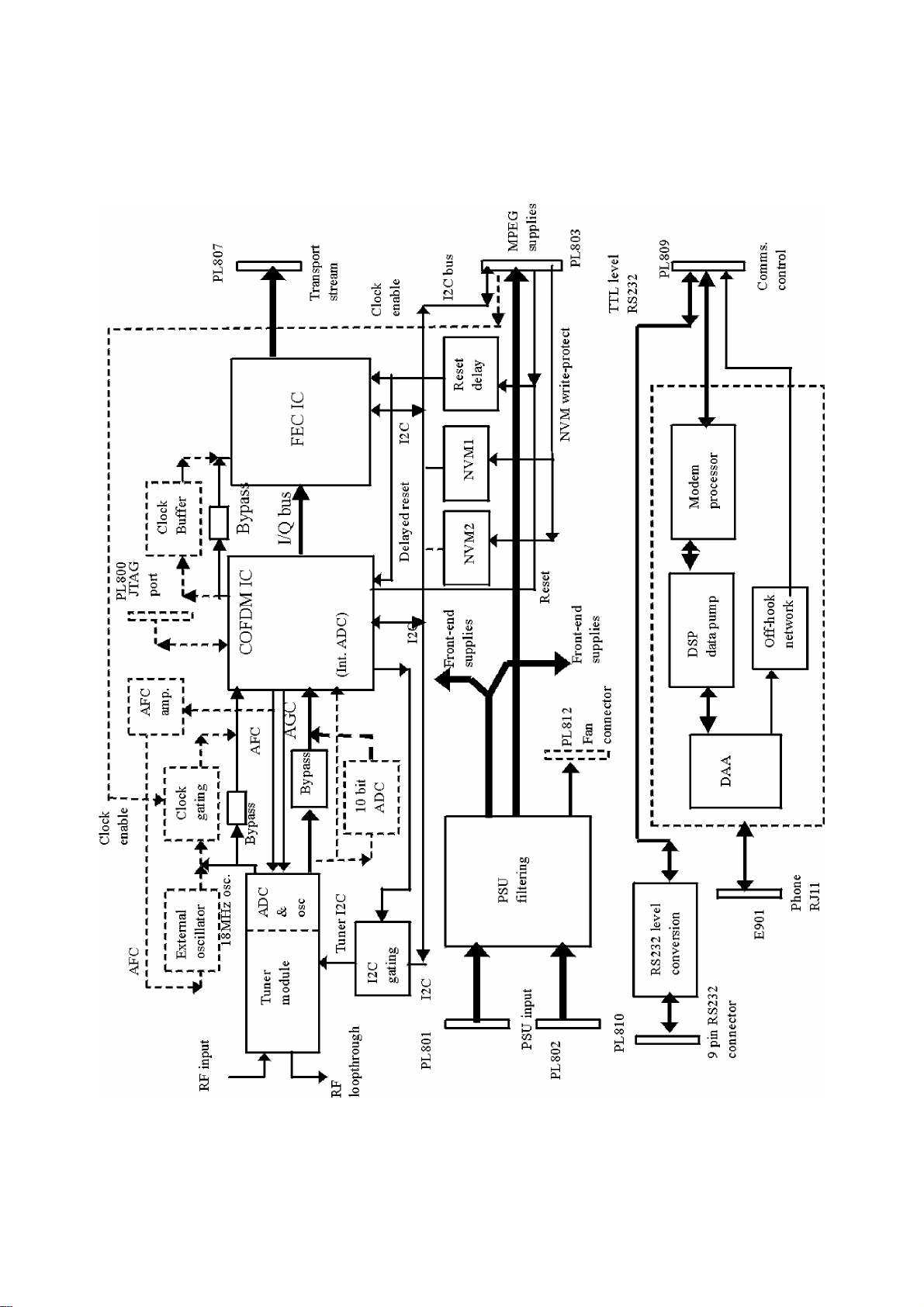
GENERAL BLOCK DIAGRAM
28
Page 30

COFDM FRONT-END PCB
This PCB carries:
• Power supply filtering
• Tuner
• COFDM decoder and FEC circuitry
• RS232 serial communications port
• V22 bis Modem
POWER SUPPLY FILTERING
This filter field is intended to filter incoming noise from the lines and to prevent noise and EMC components being carried out from
the module to the analogue section.
The power for the whole digital module is connected through this PCB, using a network of ferrite beads, chokes and capacitors. The
input power is through PL801 and PL802, and the filtered output lines are carried to the MPEG PCB on PL803, along with some
control signals from the MPEG PCB. The input and filtered/output power lines are:
Input from analogue section Common Filter
Components
5V FB800, C787, C788 Tuner COFDM tuner L801, C801, C802, C803
Modem COFDM tuner R899 (zero ohm link)
MPEG, RS232 MPEG * L805, C785, C786
5V standby L800, C771, C799 Tuner loop-through COFDM tuner None
CI chips MPEG + None
12V FB803, C795, C796 MPEG MPEG L807, C793, C794
Fan External Not used
3V3 FB802, C791, C792 COFDM / FEC COFDM tuner L804, C781, C782
MPEG MPEG * L806, C789, C790
ADC COFDM tuner L808, C779, C780
9V None Tuner COFDM tuner L802, C804, C805
30V None Tuner COFDM tuner R788, R789, R790, C806, C807
‘*’ Indicates further filtering and distribution on the MPEG PCB.
‘+’ Indicates optional linking (R783 / R784) for Common Interface power supply, see text.
Section Used on (PCB) Unique Filter components
TUNER
The tuner includes:
• UHF loop-through
• First down-converter
• Local oscillator and control PLL
• IF filter and second converter stage
• AGC control
• ADC (Analogue to Digital Converter)
• VCXO (Voltage Controlled Oscillator)
The incoming RF signal is looped back out for linking to a conventional a VCR, set-top box or the analogue TV tuner input. The
loop-through is active and has a separate 5V supply pin which is powered in both normal ‘ON’ and standby modes.
The remaining tuner sections use 5V and 9V power rails, with suitable local decoupling.
The first converter stage converts the incoming signals down so that the selected UHF channel is frequency shifted so that it is
centred within the 8MHz IF band centred around 36MHz..
The local oscillator is controlled by the PLL circuitry internal to the tuner, and the frequency selection made using the I2C bus. This
I2C bus is only gated through to the tuner for commands, which are directly addressed to it. The gating is done by IC820 and the
control signal is generated through the main COFDM IC (IC801)using a port pin. The operation of this pin is controlled through I2C
to the COFDM IC. The local pull-ups for the tuner I2C are R786, R787 and the series protection resistors are internal to the tuner.
The 36 MHz IF signal is filtered to remove the out of band frequency components, frequency shifted again down to 4.572MHz and
sampled at 4 times this frequency in the ADC.
The resolution of the ADC internal to the tuner is 8 bit, and the output from the tuner is a 8 bit wide sampled COFDM signal and the
18.288MHz sampling clock, this clock has been internally filtered to remove some of the faster edges to reduce EMC. Resistors
R884 – R889, R860 and R869, R799 are used to link the parallel data signal inputs to the COFDM IC only if the ADC in the tuner is
used. This is the normal current build but they should be omitted if an ADC external to the tuner unit is used.
The COFDM decoder IC, using the AFC feedback signal to the tuner module, controls the frequency and phase of the 18.288MHz
clock.
The gain of the IF stage is controlled by the signal from the COFDM IC, with the tuner being responsible for the crossover point and
generating the RF AGC signal which is externally linked to the RF stages.
29
Page 31

EXTERNAL 10 BIT ADC (IC803)
The option of using a 10 bit ADC external to the tuner is designed into the PCB, but is not currently used. This uses R781 R823,
R824, R825, R826, R827, R828, R831, R832, C824, C825, C826, C827, C828, C830, C831, C832, C834, C835, C836, C837, C840
and IC803. If this IC is not fitted then all the other components listed here should also be omitted from the PCB.
Link resistors R884 – R889, R860 and R869, R799 should be omitted if this IC is fitted.
EXTERNAL OSCILLATOR CIRCUIT
It may be a future requirement to use an oscillator external to the tuner module. This is accommodated on the PCB using R797,
R807 - R809, R811 – R817, R821, R822, C812 – C818, C820, C822, crystal X800, varicap diode D801, and Q800. This is not
currently used.
The circuit is a discrete Colpitt’s style crystal oscillator using the feedback from the COFDM IC to control the frequency by varying
the capacitance of the varicap diode D801. C822, R821, R822 are used to pre-bias the output for the Oscillator buffer needed
(IC800). See the section following.
AFC FEEDBACK AMPLIFIER OPTION (IC816)
An option has been on the PCB to provide an AFC voltage with more range to control the external oscillator if this is needed. This is
currently not used.
It consists of a dual op-amp configured to give a gain of 10 times with an inversion, and a possible output swing of 30V. A following
stage is added to give a further inversion with unity gain. This is made up of R833, R834, R835, R836, R837, R838, R842, C840,
IC816
Bypass links are provided across both sections by R841 (second section only) and R859 (both sections).
CLOCK BUFFERING AND GATING CIRCUIT (IC800)
This stage may be configured in one of three ways:
• With the oscillator internal to the tuner (currently populated option) it is not normally needed, and bypass resistors
R829, R830 should be fitted instead.
• In order to correct a problem on some earlier PCBs it is used as a clock gating circuit, with the function of resetting the
PLL in the COFDM IC under some startup conditions. The control is automatically provided by a control line direct from
the MPEG CPU. For this option R830 should be omitted.
• In the case where the external oscillator is used it is needed as a buffer to convert low level analogue clock to a TTL level.
In this case the PLL reset function is also available. R830 and R829 should be omitted and R797 fitted for this option.
COFDM DECODER (IC801 / L64780)
Using the 18.288MHz clock the 8 bit signal is decoded by the LSI chip (IC801) on the PCB to produce a parallel transport stream.
The clock input is fed to the COFDM IC through a 47R resistor (R810), this provides some waveform shaping and buffering between
the 5V TTL driver and the 3.3V LSI silicon.
The on-chip PLL reset pin (TEST0) is reset directly from the MPEG CPU while the main chip reset is delayed to both COFDM and
FEC ICs through R784, C772. This is done to force the COFDM IC to start up correctly reliably. Also a capacitor (C770) is fitted on
the JTAG reset pin to ensure that the COFDM chip always powers up correctly.
The control for the IF AGC is generated within the L64780 as a sigma-delta output which is filtered by R868, R795, C811. The
COFDM IC also supplies the AFC signal to the tuner VCXO, again using a filtered (R796, R847, C842, , (C841)) sigma-delta output
format.
The control (initialisation, sending of commands and reading of status) is done through the I2C bus from the MPEG CPU carried on
PL801. The serial control mode is selected by pulling the ‘S_P‘ pin high through R863, with the I2C data driven from the LSB of the
data I/O port, the remainder of the data port is used to set the I2C address which is called up during initialisation. R867, R866 are
the bus pull-ups, R864, R865 the series resistors and C870 is added on the data line correct the bus timing.
The enable control signal for the tuner I2C is provided through one port pin on this chip, it is enabled by an I2C command before
each tuner command and disabled immediately afterwards.
The L64780 contains an 8 bit ADC which can be used as an alternative to the ADC in the tuner module or the external 10 bit ADC.
The input interface components associated with this are R870, R871, R872, R873, R874, R875, C846, C847.
The L64780 contains an internal ‘x3’ PLL controlled oscillator generating a 54.864MHz signal locked to the incoming 18.288MHz
signal. This clock is provided with the data to the FEC (L64724). The local PLL power supply is filtered through R861 and C843, and
the associated PLL components are R862, C844 and C845.
The chip contains a JTAG test port which is brought out to connector PL800, with termination components R839, R840, R849,
R850, C839 to maintain the correct conditions on these pins.
The digital signal is fed to the FFT section of the L64780 COFDM decoder IC. This derives the pilot tone signals, which can be used
in conjunction with the information programmed by the MPEG CPU to decode the incoming data using an FFT algorithm into a set of
I/Q quadrature signals. These are each 3 bit resolution and provide the signals for the FEC. The IC also provides information about
the signal quality which is read back from the chip registers through the I2C bus in a form to be used in the menus for the user and
for servicing and testing.
54MHZ CLOCK BUFFER STAGE
This is needed only when a L64780 version A chips is used, it’s function is to correct the 54MHz clock drive level to the FEC. When
L64780 version B (onward) chips are used the stage is by-passed by R846. The stage is made up of IC817, C775, C776, R820
in a self biasing mode, with provision for input biasing as R793, R794.
30
Page 32

FEC IC (IC802 / L64724)
The FEC IC is used in serial control mode with the communication through the I2C bus generated by the MPEG CPU. The data port
is used for both I2C clock and data lines, and to set the device address, which is set during initialisation, in this case the serial
control mode is selected by tying the ‘HOSTMODE’ pin low. R891, R892 are the serial I2C protection resistors and C777, C778 are
added to correct the timing of the I2C bus for this chip.
The master clock for the chip is the 54.864MHz generated by the COFDM IC.
The data input from the COFDM IC is in I/Q format through link resistors R848, R851, R852, R853, R854, R855.
The functions of the FEC (Forward Error Correction) IC are:
• Quadrature decoding the data
• Removing the inner and outer convolution coding
• Viterbi decoding
• Removing the descrambling (used to ensure an approximately balanced data signal)
• Read-Solomon run-time coding (error protection) decoding.
• Derivation of information about the error statistics of the signal
The information such as Bit Error Ratio (BER), used by the CPU internally and to generate the signal quality information for the user
is obtained from the FEC IC on the I2C bus.
The transport stream signal generated by the FEC IC contains the data to be processed, demultiplexed and decoded by the
Common Interface chips and the MPEG chipset on the MPEG PCB.
On PL807 this bus carries the following signals to the MPEG PCB:
• 8 bit wide parallel data
• Data-valid
• Packet start sync
• Bit rate clock
Resistors are provided as an option for linking either packet start or error signals from the FEC but in this application the Common
Interface (to where the transport stream is linked) requires packet start. R878 should be fitted to allow this, and R877 omitted.
NVM
There are positions for two NVM chips, these can accommodate Atmel style 128kb and 256kb devices. Only one 256kb chip is
normally fitted at present (IC805) with it’s associated components C869, C893, R897 and R898. There is a ‘write-protect’ control line
provided from the CPU which disables any erroneous write operations.
RS232 SERIAL COMMUNICATIONS PORT
This chip performs the TTL to bipolar level conversion of the asynchronous serial communications link. It is made up of the AD202
IC (IC807) and it’s associated ladder/reservoir capacitors (C894, C895, C896, C897). The chip is powered from the 5V supply and
local decoupling is made up of C898, C899,
The link to the MPEG processor is TTL level with RX, TX, CTS, RTS signals. The connection to external devices is through a 9 pin
female D type socket at standard levels. Since the CPU UART peripheral is configured to use hardware flow control, the CTS is
pulled high at the output side by R792 in order to allow data to flow freely if no handshaking is provided.
V22 BIS MODEM SECTION
The Modem circuit consists of a Controller, Data Pump, and Data Access Arrangement (DAA)
The DAA provides a complete interface between data pump and a telephone line. All functions are integrated into a single hybrid
module which provides high voltage isolation.
When Loop Control is at logic 0, an active line termination is applied across Tip and Ring, at which time the device can be
considered off-hook and DC loop current will low. This is used to seize the line for an outgoing call, or if it is applied and
disconnected at the required rate, can be used to generate dial pulses. The receiver is not designed to respond to any incoming
calls.
When Off-hook, the DAA converts the balanced 2-wire input presented by the line at Tip and Ring, to a ground referenced signal at
VX. Conversely the device converts the ground referenced signal input at VR to a balanced 2-wire signal across Tip and Ring.
The Loop pin provides a voltage that is proportional to the voltage across Tip and Ring. This can be used with external circuitry to
detect a parallel phone going off-hook, and the presence of a ringing voltage.
The parallel phone detect circuit uses the loop voltage to detect a short small scale pulse. Two R-C time constants are used to
remove noise spikes, and DC information. A parallel phone going off-hook will result in a ~1s pulse going to the MPEG processor.
The ring detect circuit is a comparator that converts the loop voltage into a series of logic pulses which is passed to the controller.
The Data Pump is a synchronous single-chip modem which provides a means to construct a V.22bis modem capable of 2400 bps
full duplex over dial-up lines.
Operating over the Public Switched Telephone Network (PTSN), the Z02201 meets the modem standards for V.22bis, V.22, V.23,
V.21, Bell212A, and Bell 103.
The Z02201 performs HDLC framing at all speeds. All modulation, demodulation, filtering, A/D and D/A conversion functions for
transmit and receive are provided on-chip.
31
Page 33

The Z02201 provides comprehensive and flexible tone generation and detection. This includes all tones required to establish a
circuit connection and to set-up and control a communication session. The tone generation furnishes the DTMF tones for PTSN auto
dialling, and the supervisory tones for call establishment.
The Z02201 communicates with the controller via a parallel interface, and also allows retrieval of modem/line status, control data
and programmable coefficients.
The controller Z02205 communicates to the MPEG processor via a 5V RS232 interface, using the Hayes AT command set.
The Z02205 controls the registers and memory of the data pump via a parallel interface, allowing DTMF dialling, circuit connection,
and data transfer.
The Z02205 controls the Off-hook line to the DAA, and checks the cadence of the Ringing detect pulses for a valid ringing signal
which is communicated to the MPEG processor.
The DTR and CTS signal lines on PL809 (provisions to and from the modem) are tied low with resistor links (R781, R782) to allow
the TTL level RS232 communication to operate between the modem and CPU without handshakes being needed.
TEST POINTS ON COFDM PCB
Test Point ID Net Name Function
A001 5v tuner filtered 5V supply to tuner
A002 9v tuner filtered 9V supply to tuner
A003 9v unfiltered 9V supply to tuner
A090 30v unfiltered 30V supply to tuner
A009 30v tuner filtered 30V supply to tuner
A235 30v 1st intermediate 30V current limiting point
A234 30v 2nd intermediate 30V current limiting point
A006 RF AGC in RF AGC line tuner front can
A004 IF 1 in / out IF1 IN/OUT loop through
A008 IF 2 out IF2 OUT front can
A011 IF2 in IF2 IN rear can
A013 ADD Tuner I2C address select
A018 RF AGC out RF AGC OUT rear can
A033 Tuner out-07 Tuner ADC data out bit 7
A032 Tuner out-05 Tuner ADC data out bit 5
A031 Tuner out-04 Tuner ADC data out bit 4
A030 Tuner out-03 Tuner ADC data out bit 3
A029 Tuner out-02 Tuner ADC data out bit 2
A028 Tuner out-01 Tuner ADC data out bit 1
A027 Tuner out-00 Tuner ADC data out bit 0
TP803 Clock out Unused 18 MHz clock out from tuner
A239 18MHz Clock-in 18 MHz clock to OFDM
A005 SDA-Tuner Tuner I2C data
A012 SCL-Tuner Tuner I2C clock
A238 SDA-Tuner-SW Ungated tuner I2C data
A237 SCL-Tuner-SW Ungated tuner I2C clock
TP801 /Clock-EN active low 18.288 MHz clock enable
A236 CONTROL 18.288 MHz clock enable
A026 18MHz-Clock
TP802 IC800 spare gate unused gate IC800
TP891 IC800 spare gate unused gate IC800
A231 10 Bit-ADC
A050 INT-ADC
A051 10 Bit-ADC
A047 10 Bit-ADC
A063 REF-TF
A080 REF-TF
TP804 STBYAD10
TP805 ENDA10
TP876 DRVss
A194 3v3-COFDM 3V3 COFDM supply line
TP877 EX-AD9 External ADC data bit 9/ tuner ADC data bit 7 link through
TP878 EX-AD8 External ADC data bit 8/ tuner ADC data bit 6 link through
TP879 EX-AD7 External ADC data bit 7/ tuner ADC data bit 5 link through
TP880 EX-AD6 External ADC data bit 6/ tuner ADC data bit 4 link through
TP881 EX-AD5 External ADC data bit 5/ tuner ADC data bit 3 link through
TP882 EX-AD4 External ADC data bit 4/ tuner ADC data bit 2 link through
TP883 EX-AD3 External ADC data bit 3/ tuner ADC data bit 1 link through
32
Page 34

Test Point ID Net Name Function
TP884 EX-AD2 External ADC data bit 2/ tuner ADC data bit 0 link through
TP885 EX-AD1 External ADC data bit 1
TP886 EX-AD0 External ADC data bit 0
A007 IF-AGC tuner IF AGC line
A020 18MHz-Clock-out 18MHz clock buffered/unbuffered
A062 CLK18M Shaped 18MHz clock buffered/unbuffered
A036 EXT-OSC Colpitts oscillator VCXO voltage
A048 EXT-OSC
A025 EXT-OSC Colpitts oscillator XTAL output
A056 EXT-OSC VCXO XTAL
A045 EXT-OSC VCXO XTAL
TP800 EXT-OSC Output Colpitts oscillator
A023 EXT-OSC
A017 EXT-OSC AC coupled DC biased Colpitts oscillator output
A010 5v-OSC External oscillator 5V supply
A016 AMP_VCXO
A057 AMP_VCXO
A038 AMP_VCXO
A058 AMP_VCXO
TP806 AMP_VCXO non-inverted VCXO amplifier output
TP807 AMP_VCXO inverted VCXO amplifier output
TP888 AMP_VCXO VCXO amplifier input signal
A039 AMP_VCXO VCXO amplifier input signal
A079 VCXOCTAL Filtered VCXO signal from COFDM demod IC801
A172 VCXOCTAL Unfiltered VCXO signal from COFDM demod IC801
A061 0R0_IF_EXT_ADC
A217 3v3-COFDM 3V3 COFDM supply voltage
A067 GND-ADC
A092 SCL-780 COFDM demod I2C clock
A091 SDA-780 COFDM demod I2C data
A049 AVIN
A068 AD-VREF
A071 AD-REF
TP850 PROCQ
A087 AGC-OUT
A046 EX-AD0 External ADC data bit 0
A053 EX-AD1 External ADC data bit 1
A065 EX-AD2 External ADC data bit 2/ tuner ADC data bit 0 link through
A059 EX-AD3 External ADC data bit 3/ tuner ADC data bit 1 link through
A041 EX-AD4 External ADC data bit 4/ tuner ADC data bit 2 link through
A054 EX-AD5 External ADC data bit 5/ tuner ADC data bit 3 link through
A060 EX-AD6 External ADC data bit 6/ tuner ADC data bit 4 link through
A042 EX-AD7 External ADC data bit 7/ tuner ADC data bit 5 link through
A043 EX-AD8 External ADC data bit 8/ tuner ADC data bit 6 link through
A044 EX-AD9 External ADC data bit 9/ tuner ADC data bit 7 link through
A081 3v3-COFDM 3V3 COFDM filtered supply
A097 EXT-IN-0 Input port, not used, 0V
A093 EXT-IN-1 Input port, not used, 0V
A098 EXT-IN-2 Input port, not used, 0V
A164 RESET JTAG reset
A167 TCK JTAG clock
A173 TMS JTAG test mode select
A175 TDI JTAG test data in
A140 CLK54M 54 MHz clock out
A177 TDO JTAG data test out
A111 CLK54M ?????
TP808 /DTACK Dta acknowledge output
TP809 /INT Interrupt output
TP811 I2C-CONTROL Tunet I2C gate enable
TP812 IC780-1 Unused port pin
TP813 IC780-2 Unused port pin
A155 SD1_1 Second 4 bit output data bit 1
A156 SD1_2 Second 4 bit output data bit 2
A157 SD1_3 Second 4 bit output data bit 3
A139 SD1_3 Second 4 bit output data bit 3 link through to FEC
A138 SD1_2 Second 4 bit output data bit 2 link through to FEC
33
Page 35

Test Point ID Net Name Function
A137 SD1_1 Second 4 bit output data bit 1 link through to FEC
A136 SD0_3 First 4 bit output data 3 link through to FEC
A135 SD0_2 First 4 bit output data 2 link through to FEC
A134 SD0_1 First 4 bit output data 1 link through to FEC
A154 SD0_3 First 4 bit output data 3
A153 SD0_2 First 4 bit output data 2
A152 SD0_1 First 4 bit output data 1
A163 STARTOUT Soft decision start out from OFDM
A171 DVOUT_LP Data valid second 4 bit outputs
A151 DVOUT Data valid first 4 bit outputs
TP817 STRT780 Unused Soft decision start out from OFDM
TP818 DVLP Unused data valid second 4 bit outputs
TP819 MUX-OUT-26 MUX input bus bit 26 (test purposes only)
TP820 MUX-OUT-25 MUX input bus bit 25 (test purposes only)
TP821 MUX-OUT-24 MUX input bus bit 24 (test purposes only)
TP822 MUX-OUT-23 MUX input bus bit 23 (test purposes only)
TP823 MUX-OUT-22 MUX input bus bit 22 (test purposes only)
TP824 MUX-OUT-21 MUX input bus bit 21 (test purposes only)
TP825 MUX-OUT-20 MUX input bus bit 20 (test purposes only)
TP826 MUX-OUT-19 MUX input bus bit 19 (test purposes only)
TP827 MUX-OUT-18 MUX input bus bit 18 (test purposes only)
TP828 MUX-OUT-17 MUX input bus bit 17 (test purposes only)
TP829 MUX-OUT-16 MUX input bus bit 16 (test purposes only)
TP830 MUX-OUT-15 MUX input bus bit 15 (test purposes only)
TP831 MUX-OUT-14 MUX input bus bit 14 (test purposes only)
TP832 MUX-OUT-13 MUX input bus bit 13 (test purposes only)
TP833 MUX-OUT-12 MUX input bus bit 12 (test purposes only)
TP834 MUX-OUT-11 MUX input bus bit 11 (test purposes only)
TP835 MUX-OUT-10 MUX input bus bit 10 (test purposes only)
TP836 MUX-OUT-9 MUX input bus bit 9 (test purposes only)
TP837 MUX-OUT-8 MUX input bus bit 8 (test purposes only)
TP838 MUX-OUT-7 MUX input bus bit 7 (test purposes only)
TP839 MUX-OUT-6 MUX input bus bit 6 (test purposes only)
TP840 MUX-OUT-5 MUX input bus bit 5 (test purposes only)
TP841 MUX-OUT-4 MUX input bus bit 4 (test purposes only)
TP842 MUX-OUT-3 MUX input bus bit 3 (test purposes only)
TP843 MUX-OUT-2 MUX input bus bit 2 (test purposes only)
TP844 MUX-OUT-1 MUX input bus bit 1 (test purposes only)
TP845 MUX-OUT-0 MUX input bus bit 0 (test purposes only)
A108 INTF-MODE Serial mode select
A110 PLLP2IO VCO control voltage
A109 PLLVDD PLL VDD for internal PLL
A125 PLL filter
A146 DV780
A106 3v3 ADC Filtered 3V3 ADC supply
A055 3v3-COFDM Filtered 3V3 COFDM supply
A066 5v-MODEM Filtered 5V Modem supply
A075 5v Filtered 5V supply
A107 5v Unfiltered 5V supply
A122 3v3 Unfiltered 3V3 supply
A183 3v3 MPEG Filtered 3V3 supply
A022 5v-Tuner-STBY Filtered 5V tuner standby supply
A037 12v Unfiltered 12V supply
A040 12v-MPEG Filtered 12V supply
A123 5v Raw 5V supply to FE board
A122 GNDD Supply ground
A124 30v Raw 30V supply to FE board
A035 12v Raw 12V supply to FE board
A015 5v-Tuner-STBY Raw 5V tuner standby supply
A223 GNDD Supply ground
A227 GNDD Supply ground
A189 SDA I2C data to FEC IC802
A190 SCL I2C clock to FEC IC802
A186 CLK54M 54 MHz clock to FEC
A176 DEMOD-RESET Undelayed reset to Demod IC801
A240 DEMOD-RESET- Delayed reset to Demod/FEC
34
Page 36

Test Point ID Net Name Function
A181 3v3-COFDM Filtered 3V3 supply to FE ICs
A170 GNDD Supply ground
TP868 IC724-0 External output control pin 0
TP869 IC724-1 External output control pin 1
TP870 IC724-2 External output control pin 2
TP871 SYNC724 Synch status output
TP852 XCTR_IN External input control pin
TP853 DTACK_POL Unused data acknowledge
TP855 ADCVREFQ Unused ADC reference voltage
TP856 ADCVREFQN Unused ADC reference voltage
TP857 ADCVDDQ Unused analogue supply
TP858 ADCVSSQ Unused analogue ground
TP859 QVIN Unused Q channel data input
TP861 ADCVREF I Unused ADC reference voltage
TP862 ADCVREF IN Unused ADC reference voltage
TP863 ADCVDD I Unused analogue supply
TP864 ADCVSS I Unused analogue ground
TP865 I VIN Unused Q channel data input
A184 /COE Unused channel output enable
A191 ERR724 Transoport stream packet error from FEC
A197 FSTART Transport stream packet start from FEC
A199 BCLK Transport stream bit clock
A185 DV724 Transport stream data valid
A198 FSTARTOUT Transport stream packet start
A213 CO-7 Transport stream data out bit 7
A212 CO-6 Transport stream data out bit 6
A214 CO-5 Transport stream data out bit 5
A215 CO-4 Transport stream data out bit 4
A200 CO-3 Transport stream data out bit 3
A201 CO-2 Transport stream data out bit 2
A202 CO-1 Transport stream data out bit 1
A209 CO-0 Transport stream data out bit 0
A143 V- -10V for RS232
A128 C2- 0 to -10V square wave for generating -10V
A120 C1- 0 to +5V square wave for generating +10V from 5V
A119 C2+ 0 to +10V square wave for generating -10V from +10V
A116 C1+ +5V to +10V square wave for generating +10V from +5V
A118 V+ +10V for RS232
A221 GNDD ground for RS232 connector
A121 TX01 10V RS232 TX to 9-way D
A129 RX01 10V RS232 RX from 9-way D
A216 RS232-RX 5V RS232 RX to Mips
A133 RS232-TX 5V RS232 TX from Mips
A204 RS232-RTS 5V RS232 RTS from Mips
A144 RS232-CTS 5V RS232 CTS to Mips
A145 CTS01 10V RS232 CTS from 9-way D
A161 RTS01 10V RS232 RTS to 9-way D
TP872 MODEM-RTS 5V RS232 RTS from Mips to Modem (not used)
TP873 MODEM-DSR 5V RS232 DSR from Mips to Modem (not used)
TP874 MODEM-CTS 5V RS232 CTS to Mips from Modem (not used)
TP875 MODEM-DTR 5V RS232 CTS to Mips from Modem (not used)
A021 SDA-NVM2 I2C bus for NVM2 (data)
A013 SCL-NVM2 I2C bus for NVM2 (clock)
A034 SDA-NVM1 I2C bus for NVM2 (data)
A024 SCL-NVM1 I2C bus for NVM2 (clock)
A052 NVM-WP Write protect line for NVM chips, active high in protect mode
A229 GNDD Ground
A096 SDA ‘Network’ I2C bus (data)
A104 SCL ‘Network’ I2C bus (clock)
A224 GNDD ground for modem
A165 /RVLC mirror (reduced) of voltage across the phone line
A188 TF ringing loop sense input
A196 TXIN AC coupled telephone input signal
A211 RING DC input from telephone
A220 TIP input from telephone
DELAY
35
Page 37

Test Point ID Net Name Function
A195 VX isolated input from telephone @ 2V
A206 VX scaled down vesion of A195
A218 VX AC coupled vesion of A206 to 2.5V DC (A131)
A219 AC gnd for inverter
A230 GNDD gnd for DAA
A205 VR reduced amplitude version of A142
A142 VR AC coupled version of A132 to 2V DC
A132 VR audio signal to appear across phone lines
A169 /RVLC mirror (reduced) of voltage across the phone line
A180 /LC 0V = offhook, 5V = onhook
A207 feedback for buffer
A117 TXD- inverted signal for transmit to phone (not used)
A131 VREF reference voltage (2.5V when comunicating)
A115 CF2 internal feedback integration filter
A102 CF1 internal feedback integration filter
A178 RXI- inverted receive input
A179 RXI+ non-inverted receive inpunt
A182 feedback virtual gnd
A162 5v-AMODEM analogue 5V
A228 GNDD gnd
A103 EXTAL cyrstal oscillator input: 24.576MHz
A086 XTAL cyrstal oscillator: 24.576MHz
A078 TEST2/RCLK 0V unused input
A074 /RTS 5V unused input
A069 HD5 modem data line 5
A084 HD6 modem data line 6
A085 HD7 modem data line 7
A203 /MODEM RESET 0V = reset modem data pump IC
A100 HA0 modem address line 0
A105 HA1 modem address line 1
A101 HA2 modem address line 2
A089 /HIRQ host interupt request
A088 /HRD host read enable strobe
A095 /HWR host write enable strobe
A083 HD0 modem data line 0
A076 HD1 modem data line 1
A082 /HCS host chip select
A094 XTAL1 cyrstal oscillator input: 14.7456MHz
A099 XTAL2 cyrstal oscillator: 14.7456MHz
A073 D4 modem data line 4
A072 D3 modem data line 3
A077 D2 modem data line 2
A113 RXD 5V RS232 from mips to modem
TP900 /SHUNT pulse dial shunt relay output (not used)
A114 TXD 5V RS232 to mips from modem
A130 RING ring detect input
A149 voltage reference 0.65V
A148 mirror (reduced) of voltage across the phone line used to detect ringing signal
A232 OFFHOOK parallel phone offhok detect - 1s pulse low = parallel phone offhook
A126
A233 parallel phone offhook streached pulse
A174 parallel phone offhook short pulse
A193 /OH 0V = offhook, 5V = onhook
36
Page 38

MPEG DECODER AND AV/GRAPHICS PCB
RESET CIRCUIT
The initial power-on-reset (active low) for the CPU is generated by IC202 by monitoring the incoming 3V3 power line, with a ‘reset’
threshold at 2.9V, this signal is an active low. The output of the generator is functionally ‘OR’d with an input (active high) through
PL203 into Q200, R207, R208 from the mother board (STB or IDTV) processor which is able to force a reset of the CPU if
necessary. An inverter is provided (IC210) but not used at present.
Reset Circuit Arrangement
After the CPU is reset it generates resets through output ports for the other devices on the COFDM and MPEG PCBs timed to
guarantee the correct start-up of the circuitry on both PCBs (see CPU section). These are used for:
• COFDM/FEC
• PAL video encoder
• AV chip
• Common Interface chips A and B
MASTER CLOCK OSCILLATOR
On the MPEG PCB the system uses a single master clock VCXO centred at 27.000MHz. This is generated using a Colpitts crystal
oscillator (R248, R242, R243, R244, R212, R213, R218, R214, R217, R215, R216, L202, C237, C220, C231, C215, C206, C207,
C232, C233, C234, X200, D200, Q201). The frequency is controlled by the varicap diode (D200) with it’s DC feed from the output of
the filter section (R248, R244, R243, R242, C231, C215). The oscillator is locked to the incoming data by the PLL in the demux IC
(see below). The supply for the oscillator is decoupled through L202. The oscillator output from the emitter of Q201 is AC coupled
and biased for the clock buffer following through C234, R215, R216.
The output of the oscillator is buffered and distributed through the clock IC (IC207) which uses separate outputs for each load
device. The outputs are used for: CPU/demux IC Common Interface A and B AV decoder Video encoder Audio PLL IEEE1394 – this
is currently not supported External DRAM controller – this is currently not supported There are currently 3 unused outputs from the
clock buffer IC
Local decoupling is used (C271 - C274). Provision has been made for clock termination resistors on each chip.
AUDIO CLOCK PLL
The PLL function for the audio decoder clock is carried out by IC220. This uses the 27MHz oscillator as it’s input from the clock
buffer and produces an output at the correct frequency for the audio oversampling clock to the AV chip (256 times the audio sample
rate) as signalled in the transmission. The frequency is controlled by 3 static lines from the CI A IC (IC400), see table following. A
second output is available at 1.862MHz for a UART, this is not used. The chip is decoupled by C276.
Signal Path Diagram for Audio PLL IC
37
Page 39

The control lines are generated on port pins of the Common Interface A chip, with the values being set in one of the command
registers of that device (see section on Common Interface later).
Assuming the input reference frequency is 27MHz, the control protocol for these lines is as in the table following:
Control inputs UART clock output Audio PLL clock output
FS2 FS1 FS0 (MHz) (MHz)
0 0 0 Tristate Tristate
0 0 1 1.8620 256 x 16.0kHz
0 1 0 1.8620 256 x 22.05Hz
0 1 1 1.8620 256 x 24.00kHz
1 0 0 1.8620 256 x 32.00kHz
1 0 1 1.8620 256 x 44.10kHz
1 1 0 1.8620 256 x 48.00kHz
1 1 1 Low Low
Also see the diagram in the ‘AV decoder’ section later.
COMMON INTERFACE (CI) CIRCUITRY
The MPEG board has the provision for two common interface sockets CI A (IC400) and CI B (IC402). The implementation of the
Common Interface is undertaken by two Altera FPGA devices, one for each CI port.
Overall block Diagram of Common Interface Architecture
38
Page 40

Common Interface A (CI A) is always fitted, Common Interface B (CI B) is an optional fit. If CI B is not required it can be bypassed
by a network of resistors (R413 - R418, R420, R421, R423 - R425) on the PCB to route the transport stream direct to the demux IC.
Each chip contains the following circuit functions:
• Interface between the CPU bus and the ‘PCMCIA’ style interface on the module
• Transport stream routing control
• Control of the CI module power switch IC (IC401, IC403)
• Internal control register stack
In addition the CI A chip includes:
• Provision for a second transport stream input and routing control
• Address decoding to provide chip enables for other devices
• Control of the audio PLL
INITIALISATION
At power up the FPGA (Field Programmable Gate Array) devices need to be configured. A block of code is clocked to the devices
from the CPU using the SC1 port of the CPU (see section later) using handshaking lines and a ‘configuration’ register to confirm
correct programming of the devices. The code transferred may be the same for PCBs carrying either one or two devices, if the
second FPGA is not fitted the extra code is ignored by the first device.
Although the FPGAs are programmed devices, after they have been programmed they effectively behave as ‘hardware’ and will be
referred to ‘CI controller ICs’.
Internal control register structure
Both these devices are connected to the CPU via a 16 bit data bus and 24 bit address bus along with the associated control and
handshaking lines.
The transport stream is routed through the CI A and CI B chips in a daisy-chain manner and fed to the demux section of the
CPU/demux IC.
The CI controller ICs each have 4 internal registers to allow the state of the CI to be read/set-up by the CPU. These are as follows:
Register R/W
Status R 0 0 0 IRQ VS2 VS1 CD2 CD1
Control 0 R/W X R/rout X TsAB En1 En0 Vcc3 Vcc5
Control 1 R/W X X S/cyc I/O Reg I/face Int Reset
Configuration R X X X X X 1 1 0
7 6 5 4 3 2 1 0
Bit
39
Page 41

COMMON INTERFACE REGISTERS.
STATUS REGISTER
0 CD1 Card detect 1
1 CD2 Card detect 2
2 VS1 Voltage select 1 Determines voltage for CIS read/operation
3 VS2 Voltage select 2 used as MCLKO in CA
4 IRQ Controls card insertion/removal interrupt
5 X
6 X
7 X
CONTROL REGISTER 0
0 Vcc5En Selects 5V for PC Card supply
1 Vcc3En Selects 3.3V for PC Card supply
2 En0 Programming volts control
3 En1 Programming volts control
4 TsAB Transport stream A or B select
5 X
6 R/route Route Ts to CA card
7 X
CONTROL REGISTER 1
0 Reset PC Card RESET input
1 Int PC card interrupt
2 I/face Enables the PC Card Command & Control Interface
3 Reg Enables REG# cycle
4 I/O Selects I/O interface
5 S/cyc Enables 35ns WAIT cycle (else 100ns WAIT) (short cycle)
6 X
7 X
CONFIGURATION
0 PLL select line 0
1 PLL select line 1
2 PLL select line 2
3 X
4 X
5 X
6 X
7 X
X = Dont care
The status register reflects the state of the interface with the CI module itself for the CPU to monitor, bits 5, 6, 7 are tied low within
the device configuration and will therefore always read ‘0’. The control registers 0 and 1 allow the CPU to set the functionality of the
devices, for instance, to re-route the transport stream through the CI module if appropriate. The ‘don’t care’ bits (X) should be written
with a value of ‘0’ at initialisation. The configuration register is included as a second means for the CPU to verify the correct
programming of the internal logic and to set the audio PLL output frequency. Bits 3 - 7 are allocated for configuration verification and
are not used (set to zero). Bits 0 - 2 are used to carry the audio PLL set-up values (FS0 - FS2) for which the initialisation value is 6
corresponding to audio at 48kHz rate.
The CI controller ICs will initially be powered from 5V direct, but will superceded by 3.3V parts in future. Except for the changes to
the local power supply (information following), the change is invisible to the system. If the 3.3V devices are used the voltage
regulator IC205 and it’s associated components (C275, C246) should be fitted, and R279 by-pass omitted, while for 5V devices
R279 only should be fitted and the regulator omitted. All output logic is 3V3, but is 5V compliant. The logic thresholds are all TTL.
TRANSPORT STREAM ROUTING
The CI controller ICs allow the transport stream routing (bits 4 and 6 of Control register 0) to either be in by-pass mode (direct to the
demux IC), or through the CI socket and the CA card (and return) if one has been inserted (bits 0 and 1 Status reg.).
CI A has the provision to accept two transport stream inputs so that it may be used as a transport routing device at some time in the
future if necessary.
CONTROL AND COMMAND INTERFACE
This allows bi-directional data transfer and control interface between the CPU and the CA card inserted so that the CPU can
communicate with the CI controller IC and hence an inserted CA module and set up transport stream routing, decryption, software
upgrade etc. This is performed by 8 bit read/write cycles controlled by the internal logic of the CI controller IC and monitored by the
CPU checking the relative bits in the control registers.
40
Page 42

ADDRESS DECODE FOR CI B.
The chip enable for CI B is generated by the address decode in CI A, this enables the CPU to communicate with CI B and perform
similar CA (Conditional Access) related operations as CI A. The connections to the data and address bus are common to both
devices.
The CI A chip also provides the address mapped chip select outputs for the IEEE1394 and external CPU DRAM options which are
not currently supported in the PCB build.
This address mapping is detailed in the memory map in the CPU section (later).
CI MODULE VOLTAGE SELECT.
These output pins control the setting of the required voltages to the Vcc and Vpp lines for the common interface socket. The value
set depends on the ‘VS’ pins of the module interface and the configuration information of the CI module when inserted, and the
information is reflected in the bits 2 and 3 of the status register. The values used to control the power supply ICs (IC401, IC403) are
stored in bits 0 - 3 of control register 0. IC401 for CI A and IC403 for CI B switch the actual voltage from the 5V and 3V3 supplies.
IC401 and IC403 internally control the over-current and switching timing for these supplies.
FREQUENCY SELECT LINES FOR THE PLL ASSOCIATED WITH REV C 64108
CPU/DEMUX CHIPS.
Three select lines are used from CI A to set the sample frequency of the audio PLL (bits 0 - 2 of the configuration register).
JTAG TEST CAPABILITY
The CI chips have JTAG test capability. They are configured as part of a ‘one loop’ or ‘two loop’ test system with other chips on the
PCB, more details are given in the ‘JTAG testing’ section (section 2.6) later.
MAIN SYSTEM CPU / MPEG DEMULTIPLEXER (IC200 / L64108)
GENERAL
This IC performs four main functions on the system:
• Main system CPU
• Locking of the incoming data to the main system clock and generation of internal 54MHz clock by PLL
• Transport stream demultiplexing and SI decoding
• Packet decoding and AV data transfer to the AV chip
• Separation of PES streams to output to the IEEE1394 interface (for possible future use)
CPU FUNCTIONS
See also diagram in demultiplexer section following.
The system CPU operates internally in 32 bit mode at a clock speed of 54MHz, but with a 16 bit external data bus (E-BUS) and
memory space mapped by 24 address lines operating at 27MHz. It’s main function is the maintenance of the software program flow
to control all the devices needed for the functionality of the digital receiver. It has internal cache memory to speed up processing,
and uses external EDO DRAM (2MB) for the main processing workspace. Accommodation for up to 4MB of flash memory is
designed in as two 1M x 16 bit chips. The program start is initiated by the main ‘power-on-reset’.
In order to carry out this function and make use of the system resources this requires:
• Communications with other devices
• Asynchronous serial communications using RS232 protocol – on-board UARTs are used to communicate with the modem
and the external RS232 level converter on the front-end COFDM PCB via PL200, and with the user processor through the
Interprocessor Link (IPL) on PL203. The operation of the IPL is based on a ‘message-and-response’ protocol with the
master being the user processor under normal circumstances.
• Programming port for the CI controller ICs (CI A and CI B) – this uses the pins (SC1x) normally allocated to the second
smart card driver IC, with clock, data, acknowledge, enable and status lines.
• I2C – the CPU has an integrated peripheral to act as master for the I2C bus for all the devices on the digital section, these
are:
• Video encoder on the MPEG PCB
• Tuner on the COFDM PCB
• COFDM IC on the COFDM PCB
• FEC IC on the COFDM PCB
• NVM on the COFDM PCB
Pull-up resistors are provided on the front-end PCB on the COFDM IC and the tuner, and on the video encoder IC (R532, R533)
pulling up to 5V.
• The E-BUS gives an address space of 2
with and control the other devices on the PCB, this bus is used on the MPEG PCB, by:
• Flash memory – two chip locations are available on the PCB, but at present only a single 1M x 16bit chip is used. These
positions can accommodate 512k x 16 bit or 1M x 16 bit flash chips operating to the AMD protocol and connections.
• Common Interface (CI) controller ICs – the one or two devices fitted use the E-BUS both as a control and data/control
interface with the CPU
• The AV (Audio/Video) decoder – the E-BUS is used for passing audio-video samples from the demux to the AV decoder,
and for the necessary control communications.
• IEEE1394 fast serial interface, IC600, IC601 (not currently supported)
• External DRAM controller IC700 / IC701 (not currently supported)
23
mapped as in the table earlier in this section in 16 bit wide form to communicate
41
Page 43

• Smartcard port - the main smartcard driver port (SC0x) is used to carry all the low level controls for the CA (Conditional
Access) smartcard – reset, clock, data I/O, etc. These lines are protected by resistor / diode networks (R257 - R262,
R266, D201- D206, D209) and linked to the smartcard PCB which is mounted in the analogue section through PL204.
The CPU has a number of parallel port pins which are used to control various functions on the COFDM and MPEG PCBs,
these are:
Port Identification Input / Output Function
GP1040 O 22kHz enable for QPSK use
GP1041 O TS/NPES
GP1042 O NVM write-protest
GP1043 O Reset for PAL encoder and AV decoder ICs
GP1044 I ROM_SIZE, input sense pin
GP1045 O Reset for front_end PCB
GP1046 O Reset pulse for 18MHz clock gate on front-end PCB
GP1047 O Reset for Common Interface ICs
GP1048 O Reset for IEEE1394 chip
GP1049 I Modem off-hook input
• Local CPU memory control
• Internal cache – this is internal to the CPU
• DRAM control – the CPU has a dedicated control interface for the main DRAM. Addressing for 16Mbit (IC201) is provided
Address decoding within CI A (based on CS2) allows access to the ‘CS miss’ devices for which the chip selects are generated in the
CI A device, the timing for these data communications is then provided using the DSACK controls.
For functional reasons each interrupt group is made up of a pair, each representing an internal and an external input (12 into 6
levels), each interrupt pair is assigned a group, and the groups are prioritised. The system interrupts are allocated as follows:
and EDO type DRAM is used.
Group Function
External INT 4 / Internal NMI Level Highest
4 Timer (0-2) / RES Selectable /\
3 External INT 3 / PID processor Selectable l
2 External INT 2 / Teletext / I2C / UARTS Selectable l
1 External INT 1/ Smartcard Selectable \/
0 External INT 0 / 1284 Selectable Lowest
External Interrupts are mapped as follows
• EXTERNAL INT 4:External DRAM controller
• EXTERNAL INT 3:Common Interface B
• EXTERNAL INT 2:1394
• EXTERNAL INT 1:Common Interface A
• EXTERNAL INT 0:A/V Decoder
Note: The external interrupts have been re-arranged to enable debug on IRQ 4 while the DRAM controller is not being fitted.
The internal memory map is as below.
Triggering
Level / edge
Priority
42
Page 44

Chip select Usage Address (hex)
100.0000
Internal registers
F0.0000
Internal I/O
E0.0000
CS0 Flash bank 1 (2MB) or Boot ROM
C0.0000
CS1 Flash bank 0 (2MB)
A0.0000
CS2 Common Interface A (2MB)
80.0000
CS miss Not allocated (4MB)
40.0000 Peripheral 2MB address space mapping
40.0000
Peripherals (2MB) CS miss
23.0000
This area is mapped CS3 AV chip decoder
as shown in the 22.0000
table on the right Not Allocated
20.2000
CS miss Common Interface B
20, 0000
20.0000
Primary DRAM (2MB)
00.0000
Chip
Select
Usage Address (Hex)
(IEEE1394)
(External DRAM controller)
43
Page 45

CPU / Demux Architecture
MAIN SYSTEM CLOCK AND PLL
The 27MHz from the clock buffer is frequency/phase locked to the incoming datastream using a PLL (IC206, RR225, R223, R222,
R219, C210, C212, C208, C209, C211). The local supply is decoupled through L200, C242, and R219 is used to isolate the local
ground section.
The CPU uses a 54MHz clock internally, this is generated on-board using an internal ‘x2’ PLL loop. The 54MHz is available for test
purposes at pin 20 / TP218, through R209.
TRANSPORT STREAM DEMULTIPLEXING (L64108)
The functionality of this section covers:
• Parsing the SI data from the transport stream
• Extracting the transport stream packets for the video and audio service
• Buffering the video and audio data onto the AV chip
• Extracting the data packets associated with the graphical objects and images which are to be displayed, or acted on.
• Separation of individual PES streams
This section of the IC contains the functional circuit blocks to carry out the transport stream processing to extract the necessary
information from the SI packets of the transport stream to allow the service to be directly decoded.
It involves parsing the MPEG SI tables which carry all the data about the origin, content, timing and format of the services in the
transport stream. Most of this work is done in hardware under the control of the CPU software tasks.
44
Page 46

Having extracted the information to identify the service components video and audio components are buffered ready to pass onto
the AV chip to be decoded. The data components (MHEG, teletext, etc.) are removed from the transport stream and decoded in the
DRAM area using the appropriate software resource, e.g. bitmap expansion.
The video and audio components are passed onto the AV chip on the AV bus, this is as described in the AV chip section. The AV
chip can respond to the AV video and audio request signals by arranging to pass the data when requested, this should not normally
be needed.
The demux section also has the capability to separate PES streams which can be output through the parallel interface to the
IEEE1394 section (this IEEE1394 section is not currently supported in either software or hardware).
Data for the graphical images which are sent as objects in and decoded from the transport stream packets is passed onto the AV
chip over the E-BUS as data in burst mode.
JTAG TEST CAPABILITY
The CPU/demux chip has JTAG test capability. It can be configured either as part of a ‘one loop’ or ‘two loop’ test system with some
of the other chips on the PCB, more details are given in the ‘JTAG testing’ section later.
AV PROCESSOR IC (L64105)
The chip uses the main system clock at 27MHz from one output of the clock buffer IC.
The video and audio signals are sent from the demux IC to the AV chip on the AV bus. This is made up of:
• 8 bit wide data
• Video sample valid
• Audio sample valid
• Video sample request
• Audio sample request
• Error line
The E-BUS is used by the CPU to control the AV chip and to pass graphic image bitmaps which are to be displayed.
The data is made up of mixed audio and video samples identified by the ‘valid’ signals. The system should run such that a steady,
but not constant, audio and video data stream is passed from the demux to the AV chip. If the data is not being sent quickly enough,
signalled by the AV chip buffer contents falling below a certain level the ‘request’ lines can indicate this information back to the CPU
to request more data of that type to prevent the AV chip stalling.
The chip is capable of decoding one moving video picture and one audio service (mono, stereo or dual mono) from the packet
information sent on the AV bus from the demux IC at any time. The packets are decoded into defined buffer areas in memory and
the decoding readout rate is controlled by the timing signals contained in the signal (SCR, PCR, DTS, PTS). The video image
information should be available for playout to the video encoder at a constant rate of 25 frames/sec for PAL.
The AV chip also carries out the audio-video synchronisation using the timing information carried in the transport stream and the
packet headers. This ensures good lipsync at all times.
The AV memory area (32Mb of SDRAM) is used to ‘build’ the full video image, made up of information which has been decoded
from the video packet data and any graphics which have been generated by the CPU, e.g. menus, MHEG graphics, etc. The
graphics can either be presented as a full screen ‘graphics only’ or as an overlay on the video using various levels of transparency.
45
Page 47

AV Section Architecture
The video image can be scaled to either one half or one quarter size in the AV chip if appropriate with suitable interpolation filtering
32Mb of SDRAM running at 81MHz is used to build and store the screen image in preparation for sending the data out to the video
encoder at the correct field rate. The 81MHz clock is generated within the AV chip by ‘x3’ PLL, using C114, C115, R107. Since the
PLL is very sensitive to any extraneous signals the local power supply decoupling is provided L100, C116, C125, and the local
ground area is isolated through R113.
The SDRAM controller is a dedicated section of the AV chip. The chip selects, RAS, CAS, data and address lines are generated
synchronously with the 81MHz clock for the 2 memory ICs.
The signal bus carrying the video data to the video encoder contains:
• 8 bit wide video samples
• OSD signal
• Horizontal and vertical sync
The video samples are in 4:2:2 format synchronous to the 27MHz main clock, giving a luma (Y) sample rate of 13.5MHz and a rate
of 6.75MHz for the U and V chroma components. The OSD signal is generated by the AV chip indicating the presence of on-screen
graphics, this is not used at present. The horizontal and vertical sync signals are generated by the video encoder and the AV
decoder IC is driven in slave mode, these are both negative going sync signals. The information for the display is structured by the
AV chip in an interlaced format optimised for a normal 5 fields/sec TV display.
The audio over-sampling clock is generated by the audio PLL IC (IC220) and fed into the ACLK_32, ACLK_48 and ACLK_441 pins
of the AV chip. It is used to synchronise the decoding and readout of the audio data to the audio DAC.
The audio data signals are outputted from the AV chip in the form of serial PCM, the bus includes:
• Serial data - sequential left and right channels (ASDATA)
• Left/right sample synchronising clock (LRCLK)
• Sample rate clock (BCLK)
• Master over-sampling clock (A_CLK)
These signals are sent onto the audio DAC (see later).
to remove artifacts as far as possible.
46
Page 48

VIDEO ENCODER
The IC (IC500) used is an Analog Devices ADV7170A type which includes Macrovision capability. It is capable of generating either
PAL or NTSC video with VBI teletext, closed caption (NTSC feature) and WSS insertion. In this application we use the chip in PAL
mode and use the WSS option on scan line 23 to allow televisions which respond to it (including the TV display section of the D8
series receivers) to automatically set the optimum picture size dependent on the transmitted AFD (Active Format Descriptor)
information.
The power supply for the IC is 3.3V, but the output transistor buffers are supplied by a separate analogue 9V line direct from the
IDTV or STB motherboard. The 9V is filtered locally by L500, C500, C521, C525. The IC supply is filtered through L501, C503,
C514.
It is controlled by the I2C bus within the digital module, and the reset is generated by the CPU, common with the AV chip, the pullups are R532, R533 and the series protection resistors are R508 and R510. R509 is fitted to set the I2C address.
R507 is used to set the DAC reference currents to give the correct output amplitude.
The chip uses the main 27MHz clock as a reference to process the incoming video data, this is from the clock buffer IC.
The video input is in 8 bit parallel 4:2:2 form from the AV decoder synchronised to the main 27MHz clock.
The outputs are composite (CVBS), red (R), green (G) and blue (B), which are buffered to the video output port through transistor
buffers (Q500 – Q503, R522, R516, R17, R505, R506, R504, R514, R517, R513, R520, R519, R521). An additional filter (C501,
C518, C519, L502, L503) is used in the composite line to further reduce any possible alias products so that the video would be
suitable for a TV in which digital processing is applied. The video outputs are further filtered at the output pins of PL501 to give
EMC/ESD protection.
The system operates with the PAL encoder in master mode, i.e. it supplies horizontal and vertical sync to the AV decoder.
WSS information is sent to the video encoder by the demux in I2C form to insert into the line 23 of the composite stream. This
information is sent to the IC from the CPU on the I2C bus.
There are data and clock connections to the CPU so that VBI World Standard Teletext (WST) can be supported but this feature is
not currently used.
AUDIO DAC (DIGITAL TO ANALOG CONVERTER)
The IC (IC501) is a Crystal CS4334 type, operated from 5V to give sufficient headroom for a full SCART level audio output without
distortion. The 5V supply is locally decoupled by L505, CC508, C509, C522, C524.
The PCM serial data (ASDATA), sample clock (LRCLK), bit clock (BCLK) and oversampling master clock (A_CLK) are supplied by
the AV decoder IC to the audio DAC.
The outputs are stereo (left/right) audio are filtered by R511, R500, C504, C505 at the output (PL500) to provide some ESD and
interference protection.
There are no control or reset functions on the DAC. The output is through PL500.
EXTERNAL DRAM CONTROLLER (IC700, IC701)
GENERAL
The PCB has provision for an external DRAM controller mapped into the E-BUS. The chip select for this is provided through CI A IC.
This allows for the 16bit wide data bus and 24 bit address bus to control an extra 2MB of EDO DRAM. It uses IC700, IC701and its
associated components, but it is not used at present.
CIRCUIT DESCRIPTION
An Altera device (7128 series) is used for this function, it uses the E-BUS as a main data bus, and a chip select mapped from the CI
A chip. The DRAM supported is a 2MB (1M x 16 bit) EDO DRAM similar to that supported by the main CPU.
It is included to cover future possible requirements but it is not currently used.
JTAG TEST CAPABILITY
The Altera chip used as an external DRAM controller has JTAG test capabilty. It can be configured either as part of a ‘one loop’ or
‘two loop’ test system with some of the other chips on the PCB, more details are given in the ‘JTAG testing’ section later.
IEEE1394 INTERFACE (IC600, IC601)
GENERAL
IEEE1394 is a fast serial bus designed to operate at bitrates of 100MB/s, 200MB/s and 400MB/s. It is capable of driving over
reasonably long cable runs, e.g. between rooms, and is thus seen as a means to run full or partial transport streams to and from
display devices and sources, e.g. digital VCR.
The PCB has provision for a IEEE1394 interface with two socket positions. This requires two Texas Instruments ICs, a link layer
chip mapped into the E-BUS, and a physical layer chip. It is designed to use a chip select provided by Common Interface A IC..
The circuitry required is IC600, IC601 and the associated components.
CIRCUIT DESCRIPTION
Silicon designed by Texas Instruments has been designed in for this function. This is made up of a link layer IC (IC600) which
effectively forms part of the data protocol conversion between the controller/data source (the MPEG CPU) and the physical layer
chip (IC601)which communicates with the outside world through CN601, CN602 to provide a high speed bi-directional serial data
link.
An option for DC isolation is provided in the capacitive interface between these ICs.
This interface is not fitted to the PCBs at present.
47
Page 49

JTAG TEST CAPABILITY
The link layer chip has JTAG test capabilty. It can be configured either as part of a ‘one loop’ or ‘two loop’ test system with some of
the other chips on the PCB, more details are given in the ‘JTAG testing’ section following.
48
Page 50

JTAG TESTING
A port has been designed into the PCB to allow full JTAG testing of some of the devices. This covers:
There are five lines associated with the JTAG communication. These are:
The first 4 of these are used by all the chips, and the reset by the CPU/demux and IEEE1394 only.
It is possible to use JTAG test methods for much of the completed MPEG PCB. JTAG, also known as boundary scan testing, is a
method of loading test bit streams into chips in serial mode using a test mode clock synchronised to the data through a dedicated
port to force I/O pins into known states so that the effect can be read back. For this a test mode must be selected on the chip.
Access to and functionality of the DRAM and flash memory associated with the CPU can be tested using this method, and code can
be downloaded to the flash memory chips. This is made more efficient by the use of the CPU R/NW line to reduce the number of
cycles required to execute a read and write to the devices.
The serial bus is structured in 2 parts, one for the CPU/demux only and the second for all the other devices, this enables a more
efficient flash chip download through the JTAG link since the chain is shorter. Zero ohm resistors link options are placed to connect
the 2 loops together to all the chips in series if the JTAG code loading to the flash chip is not needed.
The JTAG test code will need to be modified if chips are to be omitted from the loops.
The net names used on the diagram attached are as we have used on the schematics, and the programming connector is 14 ways,
carrying 3 grounds. Omitted from the diagram are 10k pull ups on the following lines :R271 TDI_CPU
R272 TMS_CPU
R273 TRST_CPU
R274 TDI_CI_DRAMC_LLC
R276 TMS_CI_DRAMC_LLC
with a clock termination network fitted, consisting of 68R and 100pF in series to ground on the following :R274/C261 TCK_CPU
R277/C262 TCK_CI_DRAMC_LLC
The facility is connected such that it can be configured as a single loop through all the devices sequentially, with links R263, R264
and R265 fittted, or as two loops, covering the CPU/demux only in one loop and the other ICs in another. Resistors R412, R633 and
R700 are fitted only if the associated chip is omitted.
• CPU/Demux
• CI chips A and B
• External DRAM controller (not used at present)
• IEEE1394 Link Layer Controller (not used at present)
• TDIdata into the chip
• TDOdata out of the chip (return path)
• TMStest mode select
• TCKclock line to pass the data chain through the devices
• TRSTtest mode reset, not used by all devices.
49
Page 51

TEST POINTS ON MPEG PCB
Test Point Net Name Function
Sheet 1 AV Section
TP100 AV_D7 SDRAMdata 7
TP101 AV_D6 SDRAMdata 6
TP102 AV_D5 SDRAMdata 5
TP103 AV_D4 SDRAMdata 4
TP104 AV_D3 SDRAMdata 3
TP105 AV_D2 SDRAMdata 2
TP106 AV_D1 SDRAMdata 1
TP107 AV_D0 SDRAMdata 0
TP108 AV_DEMUX-AV_0 Multiplexed video and audio (Demux to AV) b0
TP109 AV_DEMUX-AV_1 Multiplexed video and audio (Demux to AV) b1
TP1010 AV_DEMUX-AV_2 Multiplexed video and audio (Demux to AV) b2
TP1011 AV_DEMUX-AV_3 Multiplexed video and audio (Demux to AV) b3
TP1012 AV_DEMUX-AV_4 Multiplexed video and audio (Demux to AV) b4
TP1013 AV_DEMUX-AV_5 Multiplexed video and audio (Demux to AV) b5
TP1014 AV_DEMUX-AV_6 Multiplexed video and audio (Demux to AV) b6
TP1015 AV_DEMUX-AV_7 Multiplexed video and audio (Demux to AV) b7
TP116 /AV_DEMUX-AV_ERR Data error indication
TP117 AV_DEMUX-V_AVALID Audio sample valid
TP118 AV_DEMUX-V_VVALID Video sample valid
TP119 /AV_DEMUX-AV_VREQ Request for video samples
TP120 /AV_DEMUX-AV_AREQ Request for audio samples
TP182 TOS Test function
TP181 MOT / NOT INTEL Busmode - Motorola (high) / Intel (low)
TP121 CLK_27_8 27MHz clock input to AV chip
TP122 /AV_RESET AV chip reset (active low)
TP123 /INT_AV Interrupt to CPU from AV chip(active low)
TP124 /DSACK0 Bus transfer timing control line
TP125 R/NW Read (high) / write (low)
TP126 /DS Data strobe (active low)
TP127 /AS Address strobe (active low)
TP128 /CS_AV AV chip select (active low)
TP129 /VSYNC_AV Vertical sync into AV chip (active low)
TP130 /HSYNC_AV Horizontal sync into AV chip (active low)
TP131 OSD On screen display present indicator (active high)
TP132 YC7_AV Video output 7 to encoder IC
TP133 YC6_AV Video output 6 to encoder IC
TP134 YC5_AV Video output 5 to encoder IC
TP135 YC4_AV Video output 4 to encoder IC
TP136 YC3_AV Video output 3 to encoder IC
TP137 YC2_AV Video output 2 to encoder IC
TP138 YC1_AV Video output 1 to encoder IC
TP139 YC0_AV Video output 0 to encoder IC
TP140 PLL_ACLK PCM audio oversampling clock input from PLL IC
TP141 A_CLK PCM audio oversampling clock output
TP142 BCLK PCM sample bitrate audio clock
TP143 LRCLK PCM left/right audio sample ID signal
TP144 ASDATA PCM audio data
TP179 SCAN_TE Test input
TP183 ZTEST Test input
TP145 AV_D15 SDRAM data 15
TP146 AV_D14 SDRAM data 14
TP147 AV_D13 SDRAM data 13
TP148 AV_D12 SDRAM data 12
TP149 AV_D11 SDRAM data 11
TP150 AV_D10 SDARM data 10
TP151 AV_D9 SDARM data 9
TP152 AV_D8 SDRAM data 8
TP180 SCLK SDRAM 81MHz clock direct from AV chip
TP173 SCLK_B SDRAM 81MHz clock after link resistor
TP153 AV_A9 SDRAM address 9
50
Page 52

Test Point Net Name Function
TP154 AV_A8 SDRAM address 8
TP155 AV_A7 SDRAM address 7
TP156 AV_A6 SDARM address 6
TP157 AV_A5 SDRAM address 5
TP158 AV_A4 SDARM address 4
TP159 AV_A3 SDRAM address 3
TP160 AV_A2 SDRAM address 2
TP161 AV_A1 SDRAM address 1
TP162 AV_A0 SDRAM address 0
TP163 AV_A10 SDRAM address 10
TP164 AV_A11 SDRAM address 11
TP165 /BCS1 SDRAM 1 chip select
TP166 /BCS0 SDRAM 0 chip select
TP167 /BRAS RAS SDRAM control
TP168 /BCAS CAS SDRAM control
TP169 /BWE SDRAM write enable
TP170 DQM SDRAM data control mask
TP171 LP2 PLL control
TP174 PLLVDD 81MHz phase lock loop local supply
TP172 PLLVSS 81MHz PLL local ground
TP178 LP2 (via resistor) PLL control
TP177 GNDD Digital ground
TP175 CKEA0 Clock enable, SDRAM 0
TP176 CKEA1 Clock enable, SDRAM 1
Sheet 2 CPU/Demux
TP1155 5V M-PEG 5V MPEG supply voltage
TP1040 5V_OSC 5Vsupply voltage to 27MHz oscillator voltage
TP257 MCLK_SDC 27MHz oscillator feedback
TP243 27MHzCLK 27MHz clock
TP1034 27MHz OSC2 27MHz oscillator crystal
TP1032 27MHz OSC1 27MHz oscillator crystal
TP256 27MHzOUT 27MHz oscillator output collector
TP254 CLK_27_OSCOUT Biased 27MHz oscillator clock output to buffer IC
TP997 CLK_27_0 27MHz oscillator clock output 0
TP229 CLK_27_1 27MHz oscillator clock output 1
TP998 CLK_27_2 27MHz oscillator clock output 2
TP999 CLK_27_3 27MHz oscillator clock output 3
TP263 CLK_27_4 27MHz oscillator clock output 4
TP262 CLK_27_5 27MHz oscillator clock output 5
TP226 CLK_27_6 27MHz oscillator clock output 6
TP225 CLK_27_7 27MHz oscillator clock output 7
TP224 CLK_27_8 27MHz oscillator clock output 8
TP223 CLK_27_9 27MHz oscillator clock output to CPU PLL
TP1067 PDATA_DIR Control for parallel data bus
TP218 MCLK_54 54MHz clock output after resistor
TP1061 MCLK_54_CPU 54MHz clock output direct on IC
TP1137 TCK_CPU JTAG clock to CPU
TP1141 TCK_CPU JTAG clock to CPU
TP264 TDI_CI_DRAMC_LLC JTAG data input to DRAM
TP265 TMS_CI_DRAMC_LLC JTAG Test mode set for DRAM controller/IEEE 1394 LLC chip
TP266 TDO_CI_DRAMC_LLC JTAG data output
TP267 TCK_CI_DRAMC_LLC JTAG clock input
TP268 TRST_LLC JTAG reset input
TP215 TDI_CPU JTAG data input to CPU
TP214 TDO_CPU JTAG data output to CPU
TP213 TMS_CPU JTAG Test mode set for CPU
TP212 TCK_CPU JTAG clock to CPU
TP211 TRST_CPU JTAG reset to CPU
TP234 MPEG_TO_USER_IPL_B MPEG to user interprocessor link data
TP235 USER_TO_MPEG_IPL User to MPEG interprocessor link data
TP220 18M_CLOCK_RESET 18MHz clock reset
TP201 /CI_RESET /CI_RESET
51
Page 53

Test Point Net Name Function
TP203 /1EEE1394_RESET /1EEE1394_RESET
TP219 /OFFHOOK Not off hook detect
TP249 /PALENC_AV_RESET PAL encoder reset
TP248 NVM_WP# NVM write protect
TP995 22KHZ_EN 22KHZ enable pin
TP216 TS/NPES Transport stream select
TP1105 ROM_SIZE ROM_SIZE
TP233 /TS Packet elemental stream select
TP1152 GNDD Digital ground
TP1041 USER_RESET USER_RESET (from IPL)
TP221 /RESET Not MPEG reset
TP244 MPEG_RESET MPEG_RESET
TP1097 USER_RESET base drive for user reset (from IPL)
TP217 /USER_RESET_B Not user reset (from IPL)
TP1113 SC_DET_B Smart card detect B
TP1104 SC0_C4 Smart card output 4
TP1103 SC_RST0 Smart card reset
TP1075 SC_DETECT0 Smart card detect O
TP1081 SC_CLK0 Smart card clock output
TP1102 SC0_C8 Smart card output 8
TP1037 /CS_EPROM Not chip select eprom
TP1052 /OE_ROM Not ROM output enable
TP1151 GNDD Digital Ground
TP227 RY/NBY1 Ready/ not Busy Flash 1
TP228 RY/NBY0 Ready/ not Busy Flash 0
TP1100 /CS_FLASH0 Not flash chip select 0
TP1048 /CS_FLASH1 Not flash chip select 1
TP232 SC1_I/O Smart card input/output 1
TP250 /CS_008 Not chip select 008
TP251 /BREQ Bus request
TP252 /BGACK Bus Grant acknowledge
TP253 /INT_CI1 Interupt common interface 1
TP255 /INT_1EEE1394 Interupt IEEE1394
TP258 /INT_CI2 Interupt common interface 2
TP259 /INT_DRAMC Interupt DRAM controller
TP260 /DMACK DMA acknowledge
TP261 /RESET Not reset
TP1156 ACLK Oversampling clock
TP1150 /DMREQ DMA request
TP231 /CS0 Not Chip select 0
TP1106 /CS1 Not Chip select 1
TP204 /STROBE IEEE1284/IEEE1394 data strobe
TP210 /AUTOFD IEEE1284 general purpose control
TP202 /INIT IEEE1284 peripheral initialisation
TP209 /SELECTIN IEEE1284 peripheral selection indicator
TP269 1394OUT7 1394 OUTPUT 7
TP208 /1394OVAL Not 1394 output valid
TP207 BUSY IEEE1284 peripheral busy
TP206 PERROR IEEE1284 peripheral error
TP205 SELECT IEEE1284/IEEE1394 peripheral select
TP200 /NFAULT IEEE1284 peripheral fault
TP230 MODEM_DTR Modem Data terminal ready
TP236 MODEM_CTS Modem clear to send
TP237 MODEM_DSA Modem Data set ready
TP238 MODEM_TO_CPU Modem to CPU data
TP239 CPU_TO_MODEM CPU to modem data
TP240 MODEM_RTS Modem ready to send
TP241 RS232_RX RS232 receive
TP242 RS232_TX RS232 transmit
TP1063 RS232_RTS RS232 ready to send
TP1062 RS232_CTS RS232 clear to send
TP293 PD_A4 DRAM address 4
TP292 PD_A5 DRAM address 5
52
Page 54

Test Point Net Name Function
TP291 PD_A6 DRAM address 6
TP290 PD_A7 DRAM address 7
TP289 PD_A8 DRAM address 8
TP288 /PD_RAS1 NotDRAM row address 1
TP287 /PD_CAS0H Not DRAM colum address high
TP286 /PD_CAS0L Not DRAM colum address low
TP285 PD_D8 DRAM data 8
TP284 PD_D9 DRAM data 9
TP283 PD_D10 DRAM data 10
TP282 PD_D11 DRAM data 11
TP281 PD_D12 DRAM data 12
TP280 PD_D13 DRAM data 13
TP279 PD_D14 DRAM data 14
TP278 PD_D15 DRAM data 15
TP270 PD_D0 DRAM data 0
TP271 PD_D1 DRAM data 1
TP272 PD_D2 DRAM data 2
TP273 PD_D3 DRAM data 3
TP274 PD_D4 DRAM data 4
TP275 PD_D5 DRAM data 5
TP276 PD_D6 DRAM data 6
TP277 PD_D7 DRAM data 7
TP294 PD_A0 DRAM address 0
TP295 PD_A1 DRAM address 1
TP296 PD_A2 DRAM address 2
TP297 PD_A3 DRAM address 3
TP246 /PD_WEO Not DRAM Write enable
TP247 /PD_RAS0 Not DRAM row address 0
TP1074 ZTEST LSI test pin
TP1069 LP2 CPU clock generator low pass filter
TP222 LP2 CPU clock generator low pass filter
TP299 PLLAGNDD PLL Ground
TP298 PLLVDD_P PLL 3V3 supply
TP1153 3V3_MPEG 3V3 MPEG supply voltage
TP1078 OPAMP Opamp reference
TP245 IREF Op-amp input (from cpu)
Sheet 4 Common Interface
TP316 TS/NPES Transport stream select
TP363 1394OUT0 1394 output 0
TP362 1394OUT1 1394 output 1
TP361 1394OUT2 1394 output 2
TP360 1394OUT3 1394 output 3
TP359 1394OUT4 1394 output 4
TP358 1394OUT5 1394 output 5
TP357 1394OUT6 1394 output 6
TP356 1394OUT7 1394 output 7
TP435 /STROBE IEEE1284/IEEE1394 data strobe
TP436 SELECT IEEE1284/IEEE1394 peripheral select
TP437 ERROR IEEE1284/IEEE1394 peripheral error
TP424 TS_CI_DEMUX_0 MPEG Transport 0
TP425 TS_CI_DEMUX_1 MPEG Transport 1
TP426 TS_CI_DEMUX_2 MPEG Transport 2
TP427 TS_CI_DEMUX_3 MPEG Transport 3
TP428 TS_CI_DEMUX_4 MPEG Transport 4
TP429 TS_CI_DEMUX_5 MPEG Transport 5
TP430 TS_CI_DEMUX_6 MPEG Transport 6
TP431 TS_CI_DEMUX_7 MPEG Transport 7
TP432 TS_CI_DEMUX_CLK Transport clock
TP433 TS_CI_DEMUX_VALID Transport valid
TP434 TS_CI_DEMUX_ERR Transport error
TP448 SW_PES_ERR Switch present transport error
TP447 SW_PES_EN Switch present transport enable
53
Page 55

Test Point Net Name Function
TP446 SW_PES_CLK Switch present transport clock
TP445 SW_PES_7 Switch present transport 7
TP444 SW_PES_6 Switch present transport 6
TP443 SW_PES_5 Switch present transport 5
TP442 SW_PES_4 Switch present transport 4
TP441 SW_PES_3 Switch present transport 3
TP440 SW_PES_2 Switch present transport 2
TP439 SW_PES_1 Switch present transport 1
TP438 SW_PES_0 Switch present transport 0
TP318 CD2#_B Not Card detect CI 2
TP319 101S16#_ Not 8 or 16 bit data access
TP320 MDO2_B Transport stream data out Bit 2
TP321 D2_B CI 2 Data Bus Bit 2
TP322 MDO1_B Transport stream data out Bit 1
TP323 D1_B CI 2 Data Bus Bit 2
TP324 MDO0_B Transport stream data out Bit 0
TP325 D0_B CI 2 Data Bus Bit 0
TP326 MOSTR0_B Transport stream out Packet start
TP327 A0_B CI 2 Address Bus Bit 0
TP328 MOVAL_B Transport stream out Packet valid
TP329 A1_B CI 2 Address Bus Bit 1
TP330 REG#_B CI 2 Register select
TP331 A2_B CI 2 Address Bus Bit 2
TP332 INPACK#_B CI 2 Acknowledge data transfer
TP333 A3_B CI 2 Address Bus Bit 3
TP334 WAIT#_B CI 2 Extended data transfer
TP335 A4_B CI 2 Address Bus Bit 4
TP336 RESET_B CI 2 reset module CPU
TP337 A5_B CI 2 Address Bus Bit 5
TP338 MCLKO_B CI 2 Transport stream packet clock out
TP339 A6_B CI 2 Address Bus Bit 6
TP340 A7_B CI 2 Address Bus Bit 7
TP341 MD16_B CI 2 transport stream data in Bit 6
TP342 A12_B CI 2 Address Bus Bit 12
TP343 MD15_B CI 2 transport stream data in Bit 5
TP344 MCLK1 CI 2 transport stream packet clock in
TP345 MD14_B CI 2 transport stream data in Bit 4
TP346 MIVAL_B CI 2 transport stream packet valid in
TP347 MD13_B CI 2 transport stream data in Bit 3
TP348 IREQ#_B CI 2 Interupt request from module
TP349 MD12_B CI 2 transport stream data in Bit 2
TP368 WE#_B CI 2 module memory write enable
TP369 MD11_B CI 2 transport stream data in Bit 1
TP370 A14_B CI 2 Address Bus Bit 14
TP371 MD10_B CI 2 transport stream data in Bit 0
TP380 A13_B CI 2 Address Bus Bit 13
TP381 M1STRT_B CI 2 transport stream packet start in
TP382 A8_B CI 2 Address Bus Bit 8
TP383 IOWR#_B CI 2 Module write enable
TP384 A9_B CI 2 Address Bus Bit 9
TP385 IORD#_B CI 2 Module read enable
TP386 A11_B CI 2 Address Bus Bit 11
TP387 VS1#_B CI 2 Module voltage sense pin 1
TP389 OE#_B CI 2 Module memory output enable
TP390 CE2#_B CI 2 Module enable 2
TP391 A10_B CI 2 Address Bus Bit 10
TP392 MDO7_B CI 2 transport stream data out Bit 7
TP393 CE1#_B CI 2 Module enable 1
TP394 MDO6_B CI 2 transport stream data out Bit 6
TP395 D7_B CI 2 Data Bus Bit 7
TP396 MDO5_B CI 2 transport stream data out Bit 5
TP397 D8_B CI 2 Data Bus Bit 8
TP398 MDO4_B CI 2 transport stream data out Bit 4
54
Page 56

Test Point Net Name Function
TP399 D5_B CI 2 Data Bus Bit 5
TP402 MDO3_B CI 2 transport stream data out Bit 3
TP461 /CI_RESET_B CI 2 Interface chip reset
TP462 /CONFIG_CI CI Configuration control input
TP464 VCC5_EN_B CI 2 Enable VCC to 5V
TP465 VCC3_EN_B CI 2 Enable VCC to 3V3
TP467 EN1_B CI 2 VPP enable 1
TP400 1_FLAG_B CI 2 Error indication IC403
TP468 INIT_DONE_B CI initialisation complete
TP367 RDNBSY_B CI 2 configuration ready line
TP366 CLKUSR_B CI 2 optional initialisation clock
TP469 NCS_B CI 2 chip select active low
TP470 CS_B CI 2 chip select active high
TP471 NWS_B CI 2 write strobe
TP472 NRS_B CI 2 read strobe
TP473 DEV_OE_B CI 2 enable O/Ps to tristate
TP474 DCLK_CI CI configuration data clock
TP475 DEV_CLRN_B CI 2 enable register clear
TP377 BCLKOUT Transport stream packet clock from FE to CI 1
TP379 DVALIDOUT Transport stream packet valid from FE to CI 1
TP378 FSTARTOUT/NOT_EPROM Transport stream packet start from FE to CI 1
TP403 TS_A_B_0 Transport stream data CI 1 to CI 2 bit 0
TP404 TS_A_B_1 Transport stream data CI 1 to CI 2 bit 1
TP405 TS_A_B_2 Transport stream data CI 1 to CI 2 bit 2
TP406 TS_A_B_3 Transport stream data CI 1 to CI 2 bit 3
TP407 TS_A_B_4 Transport stream data CI 1 to CI 2 bit 4
TP408 TS_A_B_5 Transport stream data CI 1 to CI 2 bit 5
TP409 TS_A_B_6 Transport stream data CI 1 to CI 2 bit 6
TP410 TS_A_B_7 Transport stream data CI 1 to CI 2 bit 7
TP411 TS_A_B_MCLK Transport stream packet clock CI 1 to CI 2
TP422 TS_A_B_MVAL Transport stream packet valid CI 1 to CI 2
TP423 TS_A_B_MSTRT Transport stream packet start CI 1 to CI 2
TP480 TS2_IN_MSTRT Transport stream packet start IEEE1394 to CI 1
TP481 TS2_IN_MVAL Transport stream packet valid IEEE1394 to CI 1
TP482 TS2_IN_MCLK Transport stream packet clock IEEE1394 to CI 1
TP483 TS2_IN_7 Transport stream data IEEE1394 to CI 1 bit 7
TP484 TS2_IN_6 Transport stream data IEEE1394 to CI 1 bit 6
TP485 TS2_IN_5 Transport stream data IEEE1394 to CI 1 bit 5
TP486 TS2_IN_4 Transport stream data IEEE1394 to CI 1 bit 4
TP487 TS2_IN_3 Transport stream data IEEE1394 to CI 1 bit 3
TP488 TS2_IN_2 Transport stream data IEEE1394 to CI 1 bit 2
TP489 TS2_IN_1 Transport stream data IEEE1394 to CI 1 bit 1
TP490 TS2_IN_0 Transport stream data IEEE1394 to CI 1 bit 0
TP412 CPU_D0 Main CPU data bus bit 0
TP413 CPU_D1 Main CPU data bus bit 1
TP414 CPU_D2 Main CPU data bus bit 2
TP415 CPU_D3 Main CPU data bus bit 3
TP416 CPU_D4 Main CPU data bus bit 4
TP417 CPU_D5 Main CPU data bus bit 5
TP418 CPU_D6 Main CPU data bus bit 6
TP419 CPU_D7 Main CPU data bus bit 7
TP420 CPU_D8 Main CPU data bus bit 8
TP421 CPU_D9 Main CPU data bus bit 9
TP449 CPU_D10 Main CPU data bus bit 10
TP450 CPU_D11 Main CPU data bus bit 11
TP451 CPU_D12 Main CPU data bus bit 12
TP452 CPU_D13 Main CPU data bus bit 13
TP453 CPU_D14 Main CPU data bus bit 14
TP454 CPU_D15 Main CPU data bus bit 15
TP455 CPU_A0 Main CPU address bit 0
TP463 CPU_A1 Main CPU address bit 1
TP494 CPU_A2 Main CPU address bit 2
TP495 CPU_A3 Main CPU address bit 3
55
Page 57

Test Point Net Name Function
TP496 CPU_A4 Main CPU address bit 4
TP497 CPU_A5 Main CPU address bit 5
TP498 CPU_A6 Main CPU address bit 6
TP499 CPU_A7 Main CPU address bit 7
TP300 CPU_A8 Main CPU address bit 8
TP301 CPU_A9 Main CPU address bit 9
TP302 CPU_A10 Main CPU address bit 10
TP303 CPU_A11 Main CPU address bit 11
TP304 CPU_A12 Main CPU address bit 12
TP305 CPU_A13 Main CPU address bit 13
TP306 CPU_A14 Main CPU address bit 14
TP307 CPU_A15 Main CPU address bit 15
TP308 CPU_A16 Main CPU address bit 16
TP309 CPU_A17 Main CPU address bit 17
TP310 CPU_A18 Main CPU address bit 18
TP311 CPU_A19 Main CPU address bit 19
TP312 CPU_A20 Main CPU address bit 20
TP313 CPU_A21 Main CPU address bit 21
TP314 CPU_A22 Main CPU address bit 22
TP315 CPU_A23 Main CPU address bit 23
TP350 NCEO_A CI 1 Configuration complete enable
TP351 EN1_A CI 1 VPP enable 1
TP352 EN0_A CI 1 VPP enable 0
TP353 VCC3_EN_A CI 1 VCC 3V3 enable
TP354 VCC5_EN_A CI 1 VCC 5V enable
TP401 I_FLAG_A CI 1 Error indication IC401
TP365 INIT_DONE_A CI 1 Initialisation complete
TP364 RDNBSY_A CI 1 configuration ready line
TP372 CLKUSR_A CI 1 optional initialisation clock
TP355 CONF_DONE_C1 CI Configuration ready/complete
TP456 RESET_A CI 1 Reset module CPU
TP457 A4_A CI 1 Address Bus Bit 4
TP373 A2_A CI 1 Address Bus Bit 2
TP374 A_PLL_2 Audio PLL select 2
TP458 DATA_CI CI Configuration data
TP375 DEV_CLRN_A CI 1 enable register clear
TP459 /CS_1EEE1394 Chip select IEEE1394 LLC
TP460 /CS_CI_B Chip select CI 2
TP376 CD7 Transport stream data FE to CI 1 bit 7
TP493 CD6 Transport stream data FE to CI 1 bit 6
TP492 CD5 Transport stream data FE to CI 1 bit 5
TP491 CD4 Transport stream data FE to CI 1 bit 4
TP479 CD3 Transport stream data FE to CI 1 bit 3
TP478 CD2 Transport stream data FE to CI 1 bit 2
TP477 CD1 Transport stream data FE to CI 1 bit 1
TP476 CD0 Transport stream data FE to CI 1 bit 0
Sheet 5 Video/Audio Output
TP504 SCRESET/RTC Sub carrier reset/real time control mode
TP515 TTXREQ Teletext data request signal
TP514 TTXDATA Teletext data input
TP516 RSET Setting for full scale amplitude of video signals
TP500 /VSYNC_AV Field/V synch
TP502 ALSB TTL address input
TP513 I2C_ADDRESS I2C_ADDRESS
TP503 /PALENC_AV_RESET /PALENC_AV_RESET
TP512 COMP PAL encoder comparater input
TP528 VREF PAL encoder reference voltage
TP544 SCL I2C clock
TP548 SDA I2C data
TP506 R/C Red/chroma output from pal encoder
TP507 G/Y Green/Luma output from pal encoder
TP508 B/CVBS Blue/CVBS output from pal encoder
56
Page 58

Test Point Net Name Function
TP509 CVBS CVBS output from pal encoder
TP535 CVBS_F CVBS output after 1st filter
TP539 CVBS_F CVBS output after 2nd filter
TP540 CVBS_F CVBS input to base of output driver
TP541 CVBS CVBS/Luma output from driver
TP532 CVBS/Y_DIG CVBS output
TP545 9V_OUTPUT 9V supply for output drivers
TP546 GNDA_OUTPUT Analogue ground
TP511 B/CVBS Blue/CVBS input to base of output driver
TP538 B/CVBSOP Blue/CVBS output of driver
TP533 B/CVBSOUT Blue/CVBS output
TP536 G/Y Green/Luma input to base of output driver
TP537 G/Y Green/Luma output of driver
TP547 G/Y_DIG Green/Luma digital output after termination
TP531 R/C Red/chroma input to base of output driver
TP542 R/C_DIG Red/chroma output from driver
TP534 R/C_DIG Red/Chroma digital output after termination
TP505 5VADAC 5V audio DAC supply votage
TP529 AOUTL Audio DAC left output
TP530 AOUTR Audio DAC right output
TP526 AOUTL Left audio output
TP527 AOUTR Right audio output
TP510 PIN8_ENABLE Pin 8 enable
sheet 6 IEEE1394
TP601 TDO_I_DRAMC_LLC JTAG
TP619 CNTNDA IEEE1394
TP600 TMS_CI_DRAMC_LLC JTAG
TP620 TDO_CI_DRAMC_LLC JTAG
TP618 /ISO IEEE1394
TP617 BDOAVAIL IEEE1394
TP616 BDIBUSY IEEE1394
TP615 CYCLEIN/SE IEEE1394
TP614 BDOF0 IEEE1394
TP613 BDOF1 IEEE1394
TP612 BDOF2 IEEE1394
TP611 TS2_IN_MIVAL Transport stream packet valid IEEE1394 to CI1
TP603 MCCTL0 IEEE1394
TP621 MCCTL1 IEEE1394
TP604 RDY IEEE1394
TP622 /INT_IEEE1394 IEEE1394
TP605 SW_PES_CLK IEEE1394
TP606 SW_PES_EN IEEE1394
TP623 SCKEN IEEE1394
TP607 TRST_LLC IEEE1394
TP608 BDIF0 IEEE1394
TP609 BDIF1 IEEE1394
TP610 BDIF2 IEEE1394
TP667 5V_MPEG 5V MPEG power supply
TP625 LREQ IEEE1394
TP626 SYSCLK IEEE1394
TP627 CTL0 IEEE1394
TP628 CTL1 IEEE1394
TP629 D0_1394 IEEE1394
TP630 D1_1394 IEEE1394
TP631 D2_1394 IEEE1394
TP632 D3_1394 IEEE1394
TP664 D0_1394 IEEE1394
TP665 SYSCLK IEEE1394
TP660 LREQ IEEE1394
TP663 STAT0 IEEE1394
TP646 STAT0 IEEE1394
TP648 IEEE1394
57
Page 59

Test Point Net Name Function
TP654 ISO IEEE1394
TP659 /PHY_RESET IEEE1394
TP661 CTL_0 IEEE1394
TP662 CTL_1 IEEE1394
TP647 PHY_POWER IEEE1394 Physical link power supply
TP643 IEEE1394
TP644 IEEE1394
TP649 OSC2 24.576MHz CLOCK
TP650 OSC1 24.576MHz CLOCK
TP653 PHY_POWER IEEE1394 Physical link power supply
TP633 IEEE1394
TP634 IEEE1394
TP635 TPA1+ IEEE1394
TP636 TPA2- IEEE1394
TP637 TPB1+ IEEE1394
TP638 TPB1- IEEE1394
TP652 MPC11 1394 IEEE1394
TP651 MPC11 1394 IEEE1394
TP641 TPA2+ IEEE1394
TP640 TPA2- IEEE1394
TP639 TPA2+ IEEE1394
VTP642 TPA2- IEEE1394
TP624 CNA IEEE1394
TP655 PC0 IEEE1394
TP656 PC1 IEEE1394
TP657 PC2 IEEE1394
TP645 CPS IEEE1394
TP666 CPS IEEE1394
Sheet7 External DRAM Controller
TP735 SIZ0 DRAM controlller data size 0
TP733 CPU_D13 Cpu data 13
TP734 /CS_DRAMC Chip select DRAM controller (External DRAM)
TP706 CLK_27_1 27 MHz clock
TP700 EBM_D0 Data bus DRAM controller to DRAM bit 0 (External DRAM)
TP701 EBM_D1 Data bus DRAM controller to DRAM bit 1 (External DRAM)
TP702 EBM_D2 Data bus DRAM controller to DRAM bit 2 (External DRAM)
TP703 EBM_D3 Data bus DRAM controller to DRAM bit 3 (External DRAM)
TP704 EBM_D4 Data bus DRAM controller to DRAM bit 4 (External DRAM)
TP705 EBM_D5 Data bus DRAM controller to DRAM bit 5 (External DRAM)
TP707 EBM_D6 Data bus DRAM controller to DRAM bit 6 (External DRAM)
TP708 EBM_D7 Data bus DRAM controller to DRAM bit 7 (External DRAM)
TP709 EBM_D8 Data bus DRAM controller to DRAM bit 8 (External DRAM)
TP710 EBM_D9 Data bus DRAM controller to DRAM bit 9 (External DRAM)
TP711 EBM_D10 Data bus DRAM controller to DRAM bit 10 (External DRAM)
TP712 EBM_D11 Data bus DRAM controller to DRAM bit 11 (External DRAM)
TP713 EBM_D12 Data bus DRAM controller to DRAM bit 12 (External DRAM)
TP714 EBM_D13 Data bus DRAM controller to DRAM bit 13 (External DRAM)
TP715 EBM_D14 Data bus DRAM controller to DRAM bit 14 (External DRAM)
TP716 TDO_I_DRAMC_LLC JTAG test data out
TP717 EBMA0 Address bus DRAM controller to DRAM bit 0 (External DRAM)
TP718 EBMA1 Address bus DRAM controller to DRAM bit 1 (External DRAM)
TP719 EBMA2 Address bus DRAM controller to DRAM bit 2 (External DRAM)
TP720 EBMA3 Address bus DRAM controller to DRAM bit 3 (External DRAM)
TP721 EBMA4 Address bus DRAM controller to DRAM bit 4 (External DRAM)
TP722 EBMA5 Address bus DRAM controller to DRAM bit 5 (External DRAM)
TP723 EBMA6 Address bus DRAM controller to DRAM bit 6 (External DRAM)
TP724 EBMA7 Address bus DRAM controller to DRAM bit 7 (External DRAM)
TP725 EBMA8 Address bus DRAM controller to DRAM bit 8 (External DRAM)
TP726 EBMA9 Address bus DRAM controller to DRAM bit 9 (External DRAM)
TP716 TDO_I_DRAMC_LLC JTAG test data out
TP727 EBM_D15 Data bus DRAM controller to DRAM bit 15 (External DRAM)
TP728 EBOE DRAM data output enable (External DRAM)
58
Page 60

Test Point Net Name Function
TP729 EBRAS1 DRAM row address select (External DRAM)
TP730 EBCAS0 DRAM column address select 0 (External DRAM)
TP731 EBCAS1 DRAM column address select 1 (External DRAM)
TP732 EBWE1 DRAM data write enable (External DRAM)
59
Page 61

CONNECTOR SPECIFICATION
GENERAL
The connections to/from the digital module are identical for both IDTV and STB applications.
The connectors which will link from either Front-End PCB or the MPEG PCB to the STB Motherboard, IDTV analogue PCB or the
smart card sub-board will use 1mm FFC connectors and cable. with the exception of the main DC power connector which will use a
2.5mm through hole system.
All the connections between the Front-end and MPEG PCBs will use 1mm FFC cable and connectors.
CONNECTIONS BETWEEN CHASSIS/MOTHERBOARD AND FRONT-END PCB
(FOR COMPLETE MODULE).
A 2.5mm pitch connector is used.
Connectors: PL801 Front-End 9 way right angle leaded - JST EH series
E5101 Mother Board 9 way straight leaded - JST EH series
Signal name Voltage Current From To No. of connection pins Pin Number
30V 30V (switched) 20mA PSU Front-End 1 1
5V 5V (switched) 0.8A typical 1.5A max PSU Front-End 2 3, 4
3V3 3.3V (switched) 2.0A typical 2.5A max PSU Front-End 2 7, 8
GND GND PSU Front-End 4 2, 5, 6, 9
Total pin requirement 9
CONNECTOR A2 - POWER SUPPLY
Connections between Chassis/Motherboard and Front-End PCB (for complete module).
A 1mm FFC and connector has been used.
Connectors:
PL802 Front-end 4 way Right angle SMT - Molex type 52207-0490 - terrestrial
7 way Right angle SMT - Molex type 52207-0790 - satellite
E5102 Mother Board 4 way straight leaded - JST type 04FMN-BTRK
Signal
name
9V 9V (switched) 90mA PSU
+12V 12V (switched)
+5VSTANDBY5V (unswitched, * see note 4) 20mA/0.6mA
22KHZOUT22kHz signal (to PSU),
13/18V
GND GND PSU
Total pin requirement 4 Terrestrial, 7 Satellite
Note 1: 4 way connector is used for terrestrial, 7 way for satellite.
Note 2: This signal is defined in detail in the note 4 related to connector E later in this document.
Note 3: The 22kHz will be switched on/off and modulated as necessary for DiSeQC by the MPEG processor.
Note 4: The PLD ICs require a small static current to hold the chip contents in standby to remove the need for reprogramming on
exit from standby.
Voltage Current From To
FrontEnd
* see notes2, 3
LNB supply 13/18V with 22kHz as required
(from PSU)
100mA (inc. fan if
used)
Not Applicable
400mA typical PSU
PSU
Front-
End
Front-
End
FrontEnd
PSU 1 4
PSU 1 5
Front-
End
FrontEnd
No. of connection
pins
1 1
1 2
1 7
2 3, 6
Pin Number
60
Page 62

CONNECTOR B - SMART CARD
Connections between MPEG PCB and Chassis/Motherboard or Card Reader Board
A 1mm FFC and connector has been used.
Connector: PL204 MPEG 12 way right angle SMT - Molex type 52207-1290
E210 Card Reader 12 way straight leaded - JST type 12FMN-BTRK
Function No. of connection pins Pin Nos.
CARD_C8 1 1
CARD_C4 1 2
CARD_I/O 1 3
CARD_CLK 1 5
CARD_RESET 1 7
CARD_VCC 1 8
SC-Detect_0 1 10
CARD_3V3 1 11
CARD_5V 1 12
GNDD 3 4, 6, 9
Total pin requirement 12
CONNECTOR C1 - VIDEO
Connections between MPEG PCB and Chassis/Motherboard.
1mm FFC cable and connector has been used.
Connector: PL501 MPEG 10 way right angle SMT - Molex type 52207-1090
E5206 Mother Board 10 way straight leaded - JST type 10FMN-BTRK
Function Net name From/to No. of connection pins Pin Nos.
Composite video (75R)
(PAL/NTSC)/Luma
Red component/Chroma R/C_DIG Module to chassis/motherboard 1 9
G component/(Luma) G/Y_DIG Module to chassis/motherboard 1 7
B component/(Composite video)
9V output supply 9V-MPEG Chassis/motherboard to module 1 1
GND GNDA 5 2, 4, 6, 8, 10
Total pin requirement 10
CVBS/Y_D
IG
B/CVBS_D
IG
Module to chassis/motherboard 1 3
Module to chassis/motherboard 1 5
CONNECTOR C2 - AUDIO
Connections between MPEG PCB and Chassis/Motherboard.
1mm FFC cable and connector has been used.
Connector: PL500 MPEG 5 way right angle SMT - Molex type 52207-0590
E5207 Mother Board 5 way straight leaded - JST type 05FMN-BTRK
Function From/to No. of connection pins Pin Nos.
Audio L Module to chassis/motherboard 1 1
Audio R Module to chassis/motherboard 1 3
GNDA Analogue ground 2 2, 4
Pin8-enable Module to chassis/motherboard 1 5
Total pin requirement 5
CONNECTOR D - CONTROL SIGNALS
Connections between MPEG PCB and Chassis/Motherboard.
1mm FFC cable and connector has been used.
Connector: PL203 MPEG 4 way right angle SMT - Molex type 52207-0490
E5280 Mother Board 4 way straight leaded - JST type 04FMN-BTRK
Function From To No. of connections Pin Nos.
USER_RESET TV MPEG 1 (provision) 1
USER_TO_MPEG_IPL TV MPEG 1 3
MPEG_TO_USER_IPL MPEG TV 1 4
GNDD
Total pin requirement 4
1
2
61
Page 63

CONNECTOR E - CONTROL
Connections and RS232 links between MPEG PCB and Front-End PCB (internal to module)..
1mm FFC cable and connector has been used.
Connector: PL200 MPEG 16 way straight SMT - JST type 16FMN-BMT-TF
PL809 Front-End 16 way straight SMT - JST type 16FMN-BMT-TF
Signal name Function No. of connection pins Pin Nos.
MODEM_DTR Modem ‘AT’ signals DTR 1 (Provision) 2
NVM_WP# NVM write protect 1 3
MODEM_CTS Modem ‘AT’ signals CTS 1 4
MODEM_DSR Modem ‘AT’ signals DSR 1 (Provision) 5
/OFFHOOK /OFFHOOK signal from modem 1 6
MODEM_to_CPU Modem ‘AT’ signals Tx 1 7
CPU_to_MODEM Modem ‘AT’ signals Rx 1 8
MODEM_RTS Modem ‘AT’ signals RTS 1 9
RS232_RX RS232 Rx 1 10
RS232_TX RS232 Tx 1 11
RS232_RTS RS232 RTS 1 12
RS232_CTS RS232 CTS 1 13
22KHZ_EN 22kHz LNB enable/modulation, see note 5 1 15
GND 3 1, 14, 16
Total pin requirement 16
Note 5: A single discrete NAND gate function is needed to gate the 22kHz signal to the PSU. This can be used in 2 ways:
The MPEG CPU will carry out the enable/diasble function and the DiSEqC modulation of the 22kHz through a port output. Also see
notes 2, 3 associated with connector A2.
• To simply enable/disable the signal - normal running mode
• To do the DiSEqC modulation using the enable/disable function - only at programme selection and only if the
DiSEqC capability is enabled.
CONNECTOR F - DATA STREAM
Connections between Front-End PCB and MPEG PCB (internal to module).
1mm FFC cable and connector has been used.
Connector: PL400 MPEG 14 way straight SMT - JST type 14FMN-BMT-TF
PL804 Front-End 14 way straight SMT - JST type 14FMN-BMT-TF
Function Estimated current No. of connection pins Pin number
CD0 1 2
CD1 1 3
CD2 1 4
CD3 1 5
CD4 1 6
CD5 1 7
CD6 1 8
CD7 1 9
BCLKOUT 1 11
DVALIDOUT 1 13
FSTARTOUT/notERROROUT 1 14
GND 3 1, 10, 12
Total pin requirement 14
CONNECTOR G - INTERNAL POWER SUPPLY LINK
Connections from Front-End PCB to MPEG PCB (internal to module).
1mm FFC cable and connector has been used.
Connector: PL202 MPEG 18 way straight SMT - JST type 18FMN-BMT-TF
PL803 Front-End 18 way straight SMT - JST type 18FMN-BMT-TF
Voltage Pin Description Current No. of connections Pin Number
5V_MPEG 2 1, 2
3.3V_MPEG 3 6, 7, 8
12V_MPEG 1 10
GND 5 3, 4, 9, 13, 17, 18
SDA I2C Bus 1 11
SCL I2C Bus 1 12
RESET# Main MPEG CPU reset 1 14
62
Page 64

18M_CLK_RESET COFDM 18-54MHz PLL reset 1 15
TUNER_RESET Tuner only reset 1 16
5-PLD-MPEG Standby 5V 1 5
Total pin requirement 18
CONNECTOR H - MOTHERBOARD TO FRONT CONTROL PANEL
Connections between Chassis/Motherboard and Front Control Panel. This is a 2mm pitch in-line captive on the Motherboard and the
Front Panel.
Connector: Motherboard E5281 Connector Type JST 13DS - 8E
Front Panel E1 Connector Type JST 13DS - 8E
Function No of connections Pin Number
Strobe 1 / Standby LED 1 1
Strobe 2 / Power LED 1 2
Strobe 3 / IR Commands received LED 1 3
Strobe 4 / On Line LED 1 4
Keyscan 0 - input 1 5
Keyscan 1 - input 1 6
Keyscan 2 - input 1 7
IR Detect 1 9
Keyscan 4 - output 1 10
Keyscan 5 - output 1 11
Keyscan 6 - output 1 12
5V 1 13
GNDD 1 8
Total pin count 13
CONNECTOR J - MOTHERBOARD TO FRONT CONTROL PANEL
See note 9
Connections between chassis/motherboard and front control panel. This is a 2.0mm pitch in-line connector on the motherboard (see
note 7) and captive on the front panel when used.
Connector: E5283 (DSTB)
Function
GNDD 2 1, 6
KEYSCAN3 note 8 1 2
Spare 1 3
SDA 1 4
SCL 1 5
Spare 1 7
Spare 1 8
Total pin count 8
Note 8: Not used at present, these lines allow expansion of up to 12 keys if required with no hardware changes on the motherboard
Note 9: Not used at present.
No of
connections
Pin Number
CONNECTOR K - IN CIRCUIT PROGRAMMING CONNECTION
Connection between chassis/motherboard and programming module. This is a 2.5mm pitch in-line connector on the motherdoard.
Connector: E5284 (DSTB)
Function
Test, see note 8 1 8
+5V 1 7
TXDATA 1 6
RXDATA 1 5
+12V 1 4
RESET#, see note 9 1 3
VPP (programming voltage) , see note 8 1 2
Port 6.0 control link 1 10
GNDD, see note 8 2 1, 9
Total pin count 10
Note 10: This allows for link blocks to be fitted across pins 1 and 2, and 8 and 9 when not in programming mode.
Note 11: This reset input must be actively pulled low (<0.5V) to reset the processor.
63
No of
connections
Pin Number
Page 65

CONNECTOR L - MOTHERBOARD TO FRONT CONTROL PANEL
Connections between Chassis/Motherboard and Front Control Panel. This is a 2mm pitch in-line captive on the Motherboard and the
Front Panel.
Connector: Motherboard E5285 Connector Type JST 12DS - 8E
Front Panel E2 Connector Type JST 12DS - 8E
Function No of connections Pin Number
7SEGA 1 1
7SEGB 1 2
7SEGC 1 3
7SEGD 1 4
GND 2 5, 11
7SEGE 1 6
7SEGF 1 7
7SEGG 1 8
7SEGDP 1 9
+5V 1 10
MAILLED 1 12
Total pin count 12
CONNECTOR M - MOTHERBOARD TO FRONT CONTROL PANEL
See note 15
This is a 2.0mm pitch in-line connector on the motherboard
Connector: E5282 (DSTB)
Function No Of Connections Pin Numbers
Spare 1 1
Spare 1 2
Spare 1 3
Spare 1 4
GNDD 1 5
Total pin count 5
Note 14: Not fitted at present This was originally used as part of the front panel connections, it is no longer used but the footprint is
on the DSTB motherboard.
CONNECTOR N - JTAG PORT CONNECTOR
See note 16
Connector used for JTAG downloading. This connector is a 14 way molex picoflex header.
Connector: PL205 (MPEG),
Function No Of Connections Pin Numbers
TDI_CPU 1 1
TDO_CPU 1 2
TMS_CPU 1 3
TDI_CI_LLC 1 4
TMS_CI_LLC 1 5
TRST-CPU 1 6
TCK_CPU 1 7
TDO_CI_LLC 1 8
TCK_CI_LLC 1 9
GNDD 1 10, 12, 14
TRST_LLC 1 11
R/NW 1 13
Total pin count 14
Note 16: This is the port normally used in production to programme the ‘boot’ section of the flash chips using JTAG as the link
protocol.
64
Page 66

CONNECTOR O – EPROM PCB CONNECTOR
See note 17
This connector is used for connecting an EPROM PCB onto the CPU data/address bus on the MPEG PCB. This is a high density 50
way connector which connects to the equivalent connector on the EPROM PCB. The type is C&CD p/n 1555 (PL206) on the MPEG
module and C&CD p/n 1554 (PL901) on the Eprom module.
Connectors: PL206 (MPEG PCB)
PL901 (Eprom PCB)
Function No Of Connections Pin Numbers
5V_MPEG 1 1
CPU_A0 1 2
CPU_A1 1 4
CPU_D0 1 5
CPU_A2 1 6
CPU_D1 1 7
CPU_A3 1 8
CPU_D2 1 9
CPU_A4 1 10
CPU_D3 1 11
CPU_A5 1 12
CPU_D4 1 13
CPU_A6 1 14
CPU_D5 1 15
CPU_A7 1 16
CPU_D6 1 17
CPU_A8 1 18
CPU_D7 1 19
CPU_A9 1 20
CPU_D8 1 21
CPU_A10 1 22
CPU_D9 1 23
CPU_A11 1 24
CPU_D10 1 25
CPU_A12 1 26
CPU_D11 1 27
CPU_A13 1 28
CPU_D12 1 29
CPU_A14 1 30
CPU_D13 1 31
CPU_A15 1 32
CPU_D14 1 33
CPU_A16 1 34
CPU_D15 1 35
CPU_A17 1 36
EPROM_OE# 1 37
CPU_A18 1 38
EPROM_CE# 1 39
CPU_A19 1 40
CPU_A20 1 42
CPU_A21 1 44
CPU_A22 1 46
3V3_MPEG 1 47
CPU_A23 1 48
GNDD 3 3, 49, 50
Spare 3 41, 43, 45
Total pin count 50
Note 16: This is not fitted.
65
Page 67

INTERCONNECTION BLOCK DIAGRAM
A8/D8 PSU
From switch on the A.C. voltage is rectified by the bridge D900 which produces approximately 300V across C918. This is then
applied to the collector of Q903 via the primary winding of T900. Initially the voltage on pin 7 of I900 will rise to approximately 16V
via R901, D929 and Q905. This allows the internal circuitry of IC900 to generate a sawtooth waveform at pin 4, from which a
squarewave output is obtained at pin6. This output is applied to the gate of Q901 which turns on and off, this alters the voltage on
the emitter of Q903 causing this device to turn on and off, generating the outputs in the secondary windings of T900.
After initial power up of I900 pin 7 is supplied from the bias winding (pin 18) of T900 via D911 for continued operation. The bias
winding voltage is also rectified by D922 which is then supplied to the base of Q905 low via R908/Q906/R924 turning Q905 off, this
is done to reduce the power dissipated by R901 once the power supply is running.
A current sense circuit consisting of R910, R939, R922 and R980 feeds back a voltage to pin 3 of I900, MAX voltage approximately
0.8V. Should the applied voltage exceed the reference the pulse width is limited from output pin 6. In this way Q903 is offered
protection from changes in primary current.
R909 and C914 act as a soft start circuit, this limits the pulse width output from pin 6 during the initial start up period, allowing a
gradual rise to full power.
Q909, R918 and associated circuitry are for reducing the frequency of the power supply when the set is in standby.
A sense voltage rectified by D922 consisting of R905 and R906, supplied pin 2 of I900, this is then compared to an internal
reference voltage. If it exceeds the internal reference the output from pin 6 will be limited by the internal error amp. Z907 will go
short if the +B exceeds 180V.
The secondary voltage induced in T900 winding 7/9 is rectified by D950, producing the H.T. voltage which is smoothed by C977. In
standby the H.T. rises slightly.
Winding 5/10 produces approximately 10V via D951, which is smoothed by C957. This is then applied to dual DC-DC converters
(+8V, +5V out). A control ramp is found on pin 2/6 I900. This ramp is formed by R944/C935, and terminated by Z913, D902, R934
network. Ramp frequency is clamped to the main PSU frequency by the winding on pin 5 T900. This ramp is compared with the
feedback level from I902 (+5) I904 (+8). The reference device monitors the output and changes the DC level to pin 5. The ramp
crosses the dc feedback level ,and the output at pins 1/7 goes low. The output at pins 1/7 starts high at the beginning of the ramp
,goes low at ramp cross level. This action via Q910, Q911 controls the pulse width and so the regulation of the +8/ +5v rails by. The
output pulse width changes with load to maintain the correct Regulating voltage.
The output of I910 pins 1,7 are buffered to improve switching losses using a push pull transistor network Q929, Q917 (for +5V). This
transistor network gives fast edge switching of Q912 (+5) and Q911 (+8V). Over current protection is provided with the current
sense resistor RP03. Network Q956 RP04/C966 pull pin 10 of I903 high if high load current is flowing through RP03.
66
Page 68

Winding 2/11 produces approximately 16V via D952, which is smoothed by C955 and then applied to Q921 through R974, which is
used as a current sense. The output from Q921 supplies 16V for the audio amplifier I401.
H.T. regulation is controlled by Q954 stage. The base of Q954 is set at a pre-determined level by the resistor network R950, R982
and R953. The emitter of Q954 is held at approximately 6V2 by Z950. Should the H.T. rise, the base voltage becomes more positive
than the emitter, and this difference is amplified by the transistor and applied to optocoupler I901. The output from I901 is then
applied to pin 1 of I900 which regulates the H.T. by altering the duty cycle of the waveform output from pin 6 of I900.
STANDBY SWITCHING
The low voltage supplies are switched off in standby, this is controlled by the micro processor which outputs a high in standby and a
low when the set is out of standby. This is then applied to resistors R923 and R940/R977. This ‘high’ is also applied to the base of
Q915, Q916, Q910 which in turn terminate operation of the +8, +5 DC-DC converters, and pull the gate of Q921 low so switching
the +16V audio supply to low state. In standby the +B voltage rises slightly to maintain bias winding voltage to pin 7 of I900. To
switch the set out of standby the on/off line is switched high by the micro, and Q916, Q915, Q910 are deactivated, causing the +8,
+5, +16V rails to return to normal operation.
POWER GOOD AND PROTECTION
I903 is made up of 4 comparators, the power good line uses comparator 2. Pin 5 is used as the reference which is held at 2.5V by
I905 supplied by pull up resistor R968. Pin 4 uses R961/R962 and R955/R959 as a potential divider which is connected between the
+10V and T900 winding through D959 which is in forward converter mode. In operation this means pin 4 is held below the reference
level of pin 5 until the mains supply is interrupted or the set is switched off at which time pin 4 rises above pin 5 and the output pin 2
is pulled low. This low is sensed by the micro. In normal operation pin 2 is held high by pull up resistor R990 from the 5V supply.
The protection line (pin 14) is held high under normal running conditions by R971 from the 5V supply, this high is applied to the
protection line to the micro. When the protection line is pulled low the set goes into standby mode, the set can be restarted by the
usual methods of bringing the set out of standby, but until the cause of the protection circuit operation is removed the set will return
to its standby state.
The over current for the 16V audio supply uses comparator 1, a reference voltage is set up on pin 6 by resistors R967, and R964.
The voltage being compared is fed to pin 7 using the potential divider R968 and R966 which is supplied from the output side of the
current sense resistor R974. Should the voltage on pin 7 fall below that of pin 6 pin 1 will be pulled low , thus pulling the protection
line low via D958 putting the set into standby.
Comparator 3 is used to protect against a layer short within the F.B.T. it will also act as protection for a short on the secondary
outputs of the F.B.T. I903 is supplied with approximately 16V via D960 to pin 3, from this supply a reference voltage is fed to pin 9
using potential divider R972/R969, fed via Z948 supply. Pin 8 is supplied by another potential divider this time made up of three
resistors R973/R970 and R760 samples the current flowing through Q752 should this increase the voltage drop across R760 will
increase and raise the voltage of pin 8 when it exceeds pin 9 and pin 14 will be pulled low putting the set into standby.
Comparator 4 is used for EHT/over voltage protection, as all the F.B.T. secondary voltages are proportional, the 200V supply to the
CRT base is used to generate the voltage to be used in comparison, this is done by using a potential divider made up of R718,
R749 and R719. Z708 monitors the voltage at the junction of R718 and R749, if this exceeds 36V the Zener diode conducts
applying a high on pin 10 of I903 this is compared with the reference voltage on pin 11 which also uses the 2.5V set up by I905.
When pin 10 is higher than 2.5V, pin 13 is pulled low in turn pulling the protection line low via D957 putting the set into standby.
The L.T. lines are given protection using diodes D931, D932 and D930 these are connected in reverse bias from the prot sense line
to the 8V and 5V. The +5V standby link is protected by D986 pulling the reference Z950 low, if a short is seen on the output of I952.
The +16V phono out has a diode back to pin 5 I903 in case of short.
If the +B or audio supply lines become short circuit to ground before the protection on the secondary of the power supply, the
primary over current protection (pin 3 I900) will operate turning off the drive output from pin 6 I900. A latch circuit
Q955/R998/RP01/C964, will operate to turn the power supply into standby ( under fault condition) if the software fauls to act on pin
14 I903 low. Delay before latch set by C964/R994. The +B is given protection from overvoltage, via Z907, Z907 goes short circuit if
the +B voltage rises above 180V DC.
DTI PSU
CIRCUIT DESCRIPTION
The mains is switched on via the { TV on }. At this point the A.C mains is rectified by D8, D10, 11, 12 which produces approximately
340v D.C across C58. This is then applied to the drain of Q4 via the primary winding of T1. Initially the voltage on pin 7 of IC10 will
rise to approximately 16v via R15, D24, and C54 this allows the internal circuitry of IC10 to generate a sawtooth waveform at pin 4
from which a square wave output is obtained at pin 6. This output is applied to the gate of Q4 turning the mosfet on and off,
generating the outputs in the secondary windings of T1.
After initial power up pin 7 of IC10 is supplied from the bias winding pin 4 of T1 via D31 for continued operation hence R15 unable to
provide running current demand for IC10 [20mA].
A current sense circuit consisting of R74, R75 & R79 feeds back a voltage to pin 3 of IC10, this voltage is compared with an internal
reference voltage, of approximately 0.8V should the applied exceed the reference, the pulse width is limited from output pin 6 [chip
in over current mode]. In this way Q4 is offered protection from changes in primary current. Secondary overvoltage protection is
offered also by R77, should the feedback be disabled then the secondary voltage will be limited to safe levels, the output from pin 6
will be limited by the internal error amplifier and internal reference.
R21 and C31 act as a soft start circuit, this limits the pulse width output from pin 6 during the initial start up period, allowing a
gradual rise to full power. ZD3 & 4 will go short if Q4 should go short, protecting IC10.
The secondary voltage induced in T1 winding 11/14 is rectified by D15 producing 38V which is smoothed by C40. This voltage is
then stepped down to provide 30V at 20mA via R96 and clamped by ZD21.
Winding 10/14 produces 5V at 1.5A when rectified by D17 and smoothed by C37 & 38. This voltage rail being the highest current rail
is used for regulation via IC8 providing feedback via IC4 to pin 1 of IC10. From the 5V rail a 3V3 rail is extracted at 2.7A. The current
output is controlled by a pwm circuit consisting of switching mosfet Q9, gate drive is provided Q10, and pin 1 of IC6, pin 2 of IC6 is
67
Page 69

supplied by a sawtooth waveform shaping circuit consists of D20, ZD9, R32, C44, D19, C43 & R30. Pin 3 is supplied by varying DC
levels via IC7 & R31. The 3V3 voltage rail is regulated by IC7.
Winding 8/14 provides 12V from D16, C35 & smoothing cap C39, also a 9V rail is provided by IC6 regulator.
SECONDARY PROTECTION: Provided via IC6 pin 7. Pin 6 of IC6 is set to a steady voltage level a round 3V, pin 5 used as the over
current sense point, D18, 25, 33 used to pull down pin 5 below pin 6 during over current in this state pin 7 is low which in turn
disables the feedback point pin 1 of IC10 shutting down the power supply.
FEEDBACK OPERATION
Increase in load demand by secondary rails results in higher voltage feedback on cathode of IC8 in turn rising the voltage on pin 1 of
IC10, this voltage is compared to the sawtooth generated on pin 4 via R76 & C95, this produces the gate drive square pulse with
larger off time therefore the larger the load demand the larger the duty cycle and vice versa.
68
Page 70

Servicing
SERVICE.
SERVICE MODE
To enter service mode from the main menu, press and hold the
'volume +' and 'volume -' buttons on the front panel of the TV
simultaneously until the 'Service' and 'Exit Service' options appear
at the bottom of the main menu.
The service option is then used to access the service menus. The
TV will remain in service mode until the 'Exit Service' option is
used to exit service mode. The install option is also always
displayed in this mode.
Whilst the TV is in service mode, the factory information will be
displayed when the TV is not in menu or teletext modes. The
information displayed is comprised of software versions, model
number and stored fault information (see below).
SERVICE MENU
This menu is displayed when the Service option is selected from
the main menu. Each of the items will display the appropriate
service sub menu. Each of the sub menus is described in detail
below
TUNER ADJUSTMENT SERVICE MENU
The options available in this menu are as follows.
• Std IF AFC. Adjusting this item will initiate the automatic
AFC alignment for standards BG/I/DK. Refer to the
alignment procedure for more information.
• L' IF AFC. Adjusting this item will initiate the automatic
AFC alignment for standard L. Refer to the alignment
procedure for more information.
• AGC T'over. This item allows adjustment of AGC
takeover. Refer to the alignment procedure for more
information.
• Def. Std. This sets the default standard for sets that
have automatic standard determination.
• Standards. This sets the list of available standards for
NB Sets that do not have automatic standard determination have a
BG on/off option and a standard option, which allows selection of 1
standard. The Def. Std and Standards options are not available on
these sets.
sets that have automatic standard determination.
• VHF. This option is used to enable VHF tuning for sets
that have a VHF (export) tuner fitted.
• AFC Offset, L' Offset. These should not be adjusted
from the factory settings.
69
Page 71

PROGRAMME ENTRY SERVICE MENU
This is the same as the menu that is accessed with the CH key in
non integrated digital sets.
VERTICAL ADJUSTMENT SERVICE
MENU
This is used to adjust the vertical deflection parameters.
HORIZONTAL ADJUSTMENT SERVICE
MENU
This is used to adjust the horizontal deflection parameters. The
RGB shift parameter is used to set the horizontal shift when an
RGB source is used. Adjusting the text shift causes a teletext test
pattern to be displayed to facilitate adjustment.
WHITE POINT ADJUSTMENT SERVICE
MENU
Refer to the alignment procedure for details on how to adjust these
parameters. Use the More… option to display the White Point
(More) Menu.
WHITE POINT (MORE) ADJUSTMENT
SERVICE MENU
Refer to the alignment procedure for details on how to adjust these
parameters. A text test pattern will be displayed when the text
brightness is adjusted. The 'Black Current' item is not adjustable
and provides a guide for adjusting the screen pot on the FBT.
70
Page 72

OPTIONS SERVICE MENU
The following options are available.
• Model Name. This allows selection of the model name,
or press OK to edit the name.
• Text Modes. This allows the allowed text modes to be
set. The options are SGL for single only, S/D for single
and dual page or SDS for single page, dual page and
NB When +T appears in the text modes option, this means that
TOP text is enabled. Some sets have a separate option to enable
TOP text.
split (text and picture, W35 models only).
• Tube Type. This should be left blank, or set to LG if the
LG tube is fitted to the set.
• M. Gating. This should be set to ON if the macrovision
gate PWB is fitted to the set.Processor. This is set to
indicate if a JBS or JBL type processor is fitted to the
set. (This is marked on the body of I001 on the main
board.)
• Pos. Sync. This should be set to ON for W30 and W35
models, and has no effect on 50Hz sets.
HOTEL OPTIONS SERVICE MENU
This menu sets hotel mode parameters. The following options are
available.
• Hotel Mode. This sets hotel mode on or off. None of the
other options have any effect unless hotel mode is on.
Note that the picture and install menus are not available
to the user when the TV is in hotel mode and not in
service mode.
• No Standby. When this option is set to ON, then the TV
will power up out of standby every time power is applied
in hotel mode. (Normally the set will remain in standby if
the set was in standby before powering down.)
• Program. This option sets the program, which is
selected whenever the TV is brought out of standby in
hotel mode.
• Max Volume. This sets the maximum volume in hotel
mode.
• DTT Program. For integrated digital sets, this sets the
initial program for the digital decoder module in hotel
mode. This is displayed when the Program item is set to
'DTT'.
E2 SETUP SERVICE MENU
· Select E2 factory when default values to E2 need to be set
automatically, usually after changing I005. · Select one of E2
Shipping settings to set shipping preferences in the E2. WARNING
Selecting one of the options above will cause changes to
adjustments and may make realignment necessary. Refer to the
alignment procedure for individual model settings. · Select Clear
Faults to reset the stored fault information (see below).
SELF DIAGNOSTICS
The TV has a method of detecting, recording and reporting details of self detected faults in order to assist in fault diagnosis,
particularly with intermittent faults.
Each recorded fault is given a fault code number and a status value. The status value consists of an indication of the fault being
currently present, how recently the problem occurred and how many times the fault has occurred. This information is stored in the
EEPROM so that it is retained until cleared by the service menu or the diagnostic interface. The occurrence of a fault results in the
present indication for that failure to be set and the failure count for that failure to be incremented up to 9.
In addition, when failures with code numbers lower than 0100 occur, the power status LED will flash to indicate the number of the
fault that has occurred. For instance, to indicate fault code 3 the LED will flash 3 times in succession followed by a pause, after
which the sequence will repeat.
The currently supported fault codes are as follows: -
71
Page 73

Fault Code Description
0000 The microprocessor was reset due to the microprocessor watchdog. This is most likely
0001 The power good line was activated (taken to ground) whilst the set was powered up.
0002 The protection line was activated (taken to ground) whilst the set was powered up.
0003 Failure of the horizontal deflection. This fault code is set when the horizontal OSD sync
0004 Failure of the vertical deflection. This fault code is set when the vertical OSD sync pulse
0005 Timeout of the black current stabilisation when the set was powering up. This will occur
0006 Failure of the microprocessor to communicate on the I2C bus as either/both of the
0007 The set failed to power up after 3 attempts. The reason for this will be evident from the
0008 The microprocessor had a power on reset, usually as a result of failure of the standby
0009 EHT overvoltage (X-Ray protection) detected. This fault occurs as a result of a voltage
000a Flash over detected. This fault occurs as a result of a voltage greater than 2 volts at pin
000b The microprocessor failed to communicate with the EEPROM (I005) due to a failure of
000c The DTT fan failure detection line was activated (taken to ground) for 10 seconds while
000d The TV received no signal for 10 minutes when in digital (where appropriate) or RF
000e (Dolby Digital sets only) Internal failure of the Dolby Digital decoder module.
Codes 01xx indicate a failure of I2C control of a device, where xx identifies that device. The supported codes are as
follows.
0184 The microprocessor failed to control the MSP3410 sound processor (I400).
018a The microprocessor failed to control the TDA9320 input processor (I200).
018c The microprocessor failed to control the TDA9330 output processor (IE02).
Codes 02xx indicate an internal reset of an I2C controlled device, the xx identifies that device. The device codes are the
same as the corresponding 01xx code. The supported codes are as follows.
0284 A power on reset of the MSP3410 sound processor (I400) was detected.
028a A power on reset of the TDA9320 input processor (I200) was detected.
028c A power on reset of the TDA9330 output processor (IE02) was detected.
Codes 0300 are related to the DTT module. These are only applicable to IDTV sets.
0300 The TV microprocessor failed to communicate with the DTT Module via the RS232 link.
0301 The DTT Module reported a failure of the AV memory.
0302 The DTT Module reported a non-volatile memory failure.
0304 The DTT Module reported a failure of the PAL encoder.
0305 The DTT Module reported a failure of the Front End Demodulator.
0306 The DTT Module reported a failure of the Front End FEC.
0307 The DTT Module reported a failure of the AFE Tuner.
0308 The DTT Module reported a failure of the Altera device (IC400).
0309 The DTT Module reported a failure of the modem.
030a The DTT Module reported a failure of the smartcard interface.
030b The DTT Module reported a signal/picture failure.
to occurs as a result of electrical disturbance, but may also happen due to a failure of
I001, I002 or I003 (where fitted).
pulse on pin 49 of I001 is missing when the set is powered up.
on pin 48 of I001 is missing when the set is powered up.
as a result of a failure of the RGB circuits between the TDA9330 (IE02 pins 40-42),
P302, the CRT base PWB and the feedback signal via P302 to IE02 pin 44.
SDA/SCL signals were shorted to ground or +5V
other fault codes.
5V supply or the main power supply shut down (due to overcurrent protection) when the
set was powered up. The count for this fault is incremented when the microprocessor is
reset and is cleared when the TV successfully powers up.
greater than 4 volts at the EHT compensation input (pin 4) of IE02.
5 of IE02 (TDA9330).
that device or the I2C bus connections.
the DTT module was powered up (digital models only). This is detected at pin 32 of
I001.
modes. This could be a problem with the aerial or a fault in the tuner module or circuitry
around I200.
This could be due to failure of the DTT power supply, the cable connections between
the TV and DTT modules or a fault internal to the DTT module.
As stated above, a status value will be stored for each fault. The status values consist of the following information: A count of the number of times that the fault has been detected. This counts up to 9 and stops. This number will only be increased
once every time the TV is powered up.
Indication of how recent the fault was. A value of 7 means the fault is the most recent, to have occurred, value of 0 means the fault
is the least recent.
72
Page 74

Indication of whether the fault is not currently present. Unless stated above, this indication is set to false when the TV is brought out
of standby and set to true when the fault is detected.
An illustration of how this information is presented on the screen is given below.
POWER CYCLE COUNTER.
A count of times the TV is powered up is kept in the EEPROM. This count increases by 1 every time the TV is powered up and is set
to zero when a fault occurs, and therefore provides an indication of the time since the last fault. When the count value reaches 30
(decimal), then all of the fault status values are automatically reset, as the faults are considered no longer important.
DISPLAY OF STORED FAULT INFORMATION.
A typical display of fault information as may be seen when the TV is in service mode is shown below. Fault code 0000
(microprocessor watchdog) is current and fault code 1 (power good line) has occurred 5 times.
This fault is the
most recent
This fault is
current.
The TV has not been powered down since the last fault occurred
List of Fault Codes
This fault has
occurred 5 times
DIAGNOSTIC INTERFACE
The television software allows for the connection of a PC to perform certain diagnostic functions. This connection operates using
pins 10 and 12 of SCART2 (AV2). This diagnostic interface is always enabled when the TV is in service mode. Also, in the situation
where a fault exists that prevents normal entry into service mode, powering up the TV with both VOL ± buttons on the front of the set
pressed simultaneously will also enable this interface.
Please contact Hitachi Home Electronics (Europe) for details of PC software and diagnostic cables to facilitate diagnostic operations
operating via this interface.
73
Page 75

FRANÇAISFRANÇAIS
Sécurité
CONSIGNES DE SECURITE
AVERTISSEMENT: vous devez respecter les précautions suivantes
POUR TOUS LES PRODUITS
1. Avant d'effectuer une intervention d'entretien sur le châssis, vous devez insérer un transformateur d'isolement entre la
ligne d'alimentation électrique et le produit.
2. Lors de la remontage du châssis dans le coffret, vérifiez que tous les dispositifs de protection sont remis en place.
3. Lorsqu'une intervention d'entretien s'avère nécessaire, respectez l'agencement d'origine des conducteurs. Vous devez
prendre des précautions supplémentaires pour garantir un agencement correct des conducteurs dans toutes les zones où
des circuits haute tension sont présents.
4. De nombreux composants électriques et mécaniques des appareils HITACHI ont des caractéristiques spéciales de
sécurité. Bien souvent, ces caractéristiques ne sont pas évidentes lors d'un examen visuel et la protection qu'ils offrent
n'est pas forcément garantie si vous utilisez des composants de rechange conçus, par exemple, pour une tension plus
élevée, une puissance plus forte. Les pièces de rechange qui offrent des caractéristiques spéciales de sécurité sont
identifiées par un repérage comportant le symbole ! sur les schémas et sur la nomenclature des pièces de rechange.
L'emploi d'un
5. composant de rechange qui ne respecte pas les mêmes caractéristiques de sécurité que la pièce de rechange que
recommande HITACHI et qui figure dans la nomenclature risque de provoquer un choc électrique, un incendie, des
rayons X ou d'autres dangers.
6. Remettez toujours en place les entretoises d'origine et respectez la longueur des conduites. En outre, à la suite d'un
court-circuit, remplacez les composants présentant des signes de surchauffe.
7. La résistance d'isolement doit être supérieure ou égale à 2 méga ohms à 500 V c.c. entre les pôles principaux et des
composants métalliques accessibles, quels qu'ils soient.
8. Aucun claquage et aucune rupture ne doit se produire pendant l'essai de résistance diélectrique à la suite de l'application
d'une tension de 3 kV c.a. ou de 4,35 kV c.c. pendant deux secondes entre les pôles principaux et des composants
métalliques accessibles.
9. Avant de remettre au client un produit qui a fait l'objet d'un entretien, le technicien qui s'est chargé de cette intervention
doit tester à fond cet ensemble pour s'assurer qu'il ne présente aucun danger opérationnel et aucun risque de choc
électrique. Ce technicien doit s'assurer qu'aucun des dispositifs de protection intégrés à cet instrument par le fabricant
n'est défectueux ou n'a été endommagé de façon accidentelle lors de l'entretien.
LABEL CE
1. Les produits HITACHI peuvent avoir reçu le label CE qui figure sur la plaque signalétique pour indiquer que cet ensemble
contient des composants qui ont fait l'objet d'une homologation spécifique de respect des normes de compatibilité
électromagnétique en fonction de niveaux bien spécifiés.
2. Lors du remplacement d'un des composants de ce produit, utilisez uniquement le composant correct identifié dans la
nomenclature afin de maintenir le respect de cette norme ; en outre, vous devez également ramener l'agencement des
conducteurs à son état d'origine car cela peut avoir une influence au niveau des rayonnements électromagnétiques et sur
la protection contre ces rayons.
PICTURE TUBE
1. L'étage de sortie des lignes peut développer des tensions de plus de 25 kV ; s'il faut retirer le chapeau de protection
contre les tensions extrêmement élevées, il convient de décharger l'anode contre le châssis par le biais d'une résistance
de forte valeur avant de déposer ce chapeau du tube image.
2. La haute tension doit toujours se maintenir à la valeur nominale du châssis et ne pas dépasser cette dernière. Un
fonctionnement à des températures élevées peut provoquer une défaillance du tube image ou l'entrée d'une tension
élevée. Dans certains cas, cela peut même provoquer des rayons X d'un niveau légèrement supérieur aux valeurs de
calcul. Cette haute tension ne doit en aucun cas dépasser 29 kV sur le châssis (à l'exception des téléviseurs de
projection).
3. La principale source de rayons X de cet appareil est le tube image. Le tube image employé pour assurer la fonction
susmentionnée dans ce châssis est spécialement construit pour limiter des rayons X. Pour maintenir cette protection
contre les rayons X, il faut remplacer le tube d'origine d'un type agréé par HITACHI par un autre tube de même type.
4. Lors des manipulations, ne tenez jamais le tube image contre le corps. Pendant toutes les opérations d'installation, de
dépose et de manipulation de ce tube image, quelle que soit la méthode employée, vous devez toujours porter des
lunettes de sécurité anti-éclatements. Les personnes qui ne portent pas ce type de lunettes doivent se tenir à l'écart du
tube image lors de la manipulation de ce dernier.
RAYONS LASER
Si ce produit contient un rayon laser, évitez toute exposition directe à ce faisceau lors de l'ouverture du couvercle ou lors de
l'élimination des verrouillages de sécurité ou après défaillance de ces verrouillages.
74
Page 76

DESCRIPTION DU CIRCUIT
PROCEDURE D'ALIGNEMANT DU COFFRET D8/A8
APPLICATIONS
CETTE SPECIFICATION DOIT S'APPLIQUER A TOUS LES RECEPTEURS A8 DESTINES AU ROYAUME-UNI ET A
L'EXPORTATION
REGLAGE DE L'ENSEMBLE CARTE P.W.B
POUR LES SIGNAUX
PREPARATIFS DE REGLAGE
• Ajust.+B VR982.......... Centre
• Ecran VR (FBT)....... A fond dans le sens inverse des aiguilles d'une montre
• Mettez l'appareil sous tension. Réglez +B sur environ 152 V. (Préréglage uniquement - voir réglage final de +B à la
section intitulée REGLAGE DE TENSION +B)
• Si un flamboiement est détecté, réglez L501 jusqu'à ce qu'un signal vidéo propre apparaisse sur le port de sortie vidéo de
Sur les modèles qui ont un dispositif flash, vérifiez que l'information de service indique FLASH : x.x et non pas Code : x.x pour la
version logicielle.
ALIGNEMENT STANDARD AFC
l'oscilloscope.
• Pour réduire l'influence de la dérive de température des circuits, attendez que le poste de télévision soit monté en
température en le laissant fonctionner normalement pendant plus de deux minutes.
• Recevez un signal "PAL I" en sélectionnant l'option program 3 sur la télécommande.
• Recevez un niveau de signal de +60 dBuV en 623,25 MHz (CH40) en choisissant l'option Entrée fréquence directe
(Direct frequency entry) à la fonction CH.
• Réglez le décalage AFC (options en service) sur la position centrale.
• Dans le menu du tuner, sélectionnez l'option Fréquence intermédiaire standard I.F. AFC puis appuyez sur la touche "<"
ou ">" de la télécommande pour enclencher la procédure de réglage automatique de l'option AFC.
• Si la barre indicatrice arrive à une ou l'autre des extrémités, ramenez-la à la partie centrale, ajustez L201 sur un tour puis
reprenez l'opération 3. Continuez cette procédure jusqu'à ce que la barre indicatrice ne revienne plus au centre.
ALIGNEMENT L'AFC (POUR MODÈLES DESTINÉS À L'EXPORTATION UNIQUEMENT).
• Pour réduire l'influence de la dérive de température des circuits, attendez que le poste de télévision soit monté en
température en le laissant fonctionner normalement pendant plus de deux minutes.
• Recevez un signal L' en sélectionnant le programme 14 sur la télécommande.
• Recevez un niveau de signal +60 dBuV en 63,75 MHz (CH4) en saisissant l'option Entrée fréquence directe (Direct
frequency entry) à la fonction CH.
• Sur le menu du tuner, sélectionnez l'option Fréquence intermédiaire L' I.F AFC puis appuyez sur la touche "<" ou ">" de la
télécommande.
• Si la barre indicatrice arrive à une ou l'autre des extrémités, ramenez-la à la partie centrale, ajustez L201 sur un tour puis
Etant donné que les procédures de programmation sont interactives, il faut recommencer toutes les procédures depuis
L'ALIGNEMENT AFC STANDARD jusqu'à ce qu'un réglage de L201 ne s'avère plus nécessaire.
ALIGNEMENT DU CONTROLE AUTOMATIQUE DE GAIN AGC
reprenez l'opération 3. Continuez cette procédure jusqu'à ce que la barre indicatrice ne revienne plus au centre.
• Pour réduire l'influence de la dérive de température des circuits, attendez que le poste de télévision soit monté en
température en le laissant fonctionner normalement pendant plus de deux minutes.
• Branchez un voltmètre offrant une résistance interne d'au moins 100K sur la borne A.G.C. du tuner.
• Recevez le canal 40 (623,25 mHz) en +60 dBuV.
• Ajustez le contrôle de gain A.G.C. en utilisant l'option de prise en main du contrôle de gain (A.G.C. take-over) du sous-
menu du tuner jusqu'à ce que la tension A.G.C. soit égale à 2,8 V +/- 0,1 V.
75
Page 77

AJUSTEMENT DE LA PUISSANCE ET DE LA DEFLEXION
AJUSTEMENT DE LA TENSION +B
• Tension d'entrée secteur = 230 V ± 5 V/50 Hz
• Amenez la tension +B (R982) au point médian (si un préréglage n'est pas réalisé).
• Recevez la mire de circuit Philips. Mettez l'appareil sous tension puis réglez la luminosité et le contraste sur leurs valeurs
maximales.
• Après un fonctionnement de montée en chaleur d'au moins 1 MINUTE, tournez progressivement R982 et ajustez +B
(revérifiez au bout de 30 secondes)
• Réglez la tension +B sur la valeur qui figure dans le tableau ci-dessous.
• Vérifiez la tension +B dans le mode de veille : elle doit être > 145 V et < 160 V.
Effectuez un essai en court-circuit (de tous les rails). Le groupe d'alimentation électrique doit passer dans le mode de
veille/réinitilisation/blocage (pour effectuer la remise en route, il faudra probablement retirer l'alimentation). Il faut tester le rail audio,
source Q921 sur 0 V.
Point de mesure: Tension +B côté C958 +
Mise à la masse côté C958 -
MODELE TENSION +B (V)
Tous D8 151 V ± 0,2 V
Tous A8 148 V ± 0,2 V
Charge mini Charge maxi
+8 V = 8 V ± 5% 0,3 A 0,8 A
+5 V = 5 V ± 5% 0,3 A 0,8 A
+16 V = 16 V ,+3 V – 0,5 V 0 A 1,6 A
+16 V (Phono) = +16 V, (+ 3 V, - 1 V) 0 A 200 mA
+B 0,2 A 0,8 A
AJUSTEMENT DE PUISSANCE ET DE DEFLEXION
BONNE LIGNE D'ALIMENTATION ELECTRIQUE
• Réglez l'image sur les mêmes paramètres que précédemment.
• Effectuez une mesure sur la broche 2 de l'I903. Elle doit être HAUTE. Si elle est BASSE, coupez R962 (le cas échéant).
Si elle est HAUTE mais s'il n'y a pas de synchronisation de la réduction de puissance (voir ci-dessous), coupez R955 (le
cas échéant).
• Vérifiez la synchronisation logique de la réduction de puissance (> 40 ms, < 300 ms).
* Après avoir réglé la bonne ligne électrique, vérifiez le fonctionnement sur la tension secteur de 200 V c.a.
LIMITE DU COURANT PRIMAIRE
(Préréglage de R980 sur le point médian)
Rail Charge de coupure Charge de vérification Puissance de coupure Puissance de vérification
+B 1,2 A c.c. 1,1 A 180 W 165 W
+16 V 2,24 A c.c. 1,65 A 36 W 26 W
+11 V
(+5, +8)
TOTAL W 234 W 209 W
• Dans le mode de veille, appliquez la pleine charge +40% sur les rails +B et audio/+11 V (charge dynamique) comme
indiqué sur le tableau ci-dessus.
• Ajustez R980 jusqu'à ce que l'appareil se mettre hors circuit.
• Dans le mode de veille, appliquez la charge de vérification. Le groupe d'alimentation électrique ne doit pas se mettre hors
circuit.
1,60 A 1,60 A 18 W 18 W
76
Page 78

VERIFICATION DU FONCTIONNEMENT DANS LE MODE DE VEILLE
• Vérifiez que tous les rails (à l'exception de +B et de veille +5 V) passent à 0 V.
• Vérifiez que +B ne s'élève pas à plus de 160 V
VERIFICATIONS GENERALES DE SECURITE
• Effectuez un essai à haute tension conforme à la BEAB pour confirmer les composants en travers de la barrière (y
compris la sous-carte).
• Un essai d'orientation d'insertion de relais Deg (ce relais peut être monté en position inversée sur le support de console
de groupe d'alimentation électrique principal et secondaire). + fiche de travail indiquant l'orientation du relais.
VERIFICATION DU GROUPE D'ALIMENTATION ELECTRIQUE DE SOUS-CARTE (DTT/GRAVES/GROUPE D'ALIMENTATION
ELECTRIQUE DE CONSOLE)
• Essai de court-circuit (sur tous les rails)
• Essai de tension de sortie (sur tous les rails), voir tableau.
• Fonctionnement dans le mode de veille. Tous les rails doivent être hors circuit. +10 V restent pour alimenter la sous-carte
groupe d'alimentation électrique et opto.
• Vérification d'un fonctionnement à pleine charge.
RAIL DTT GRAVES CONSOLE
38 V / 0,62 A 0,2 A
32 V / / 0,92 A
9 V 400 mA / /
5,1 V 1,5 A Utilisé pour silencieux Utilisé pour silencieux
3 V3 2,7 A / /
30 V 10 mA / /
12 V 10 mA / /
REGLAGE DTT +5 V
• Réglez VR1 sur sa position approximativement centrale (10 kW).
• Mettez l'alimentation sous tension puis appliquez une charge externe, voir tableau.
• Ajustez VR1 en vous assurant que le rail +5,2 V soit correct à ± 0,05 V près.
IL FAUT EFFECTUER UN ESSAI CONCU PAR LA BEAB SUR LA SOUS-CARTE, DANS UN APPAREIL OU SUR UN
SUPPORT DE CONSOLE
VERIFICATION DU CIRCUIT LIMITEUR DE HAUTE TENSION
• Montez la carte PW sur l'appareil et ajustez-la normalement.
• Recevez le signal de mire circulaire.
• Réglez le contraste et la luminosité sur leurs valeurs maximales.
• Ajoutez R = 470K en parallèle avec R718 et R718A.
• Vérifiez que l'image et le son disparaissent lorsque R est ajouté.
REMARQUE :
Bâti de circuit limiteur de haute tension :
2
25",28" 47K 4K7
28" 16/9 47K 4K7
32" 16/9 47K 4K7
VERIFICATION DU CIRCUIT DE PROTECTION DE COURT-CIRCUIT TENSION ANODIQUE/MISE AU POINT
• Ajoutez une tension continue sur R760 jusqu'à ce que l'appareil se mette hors circuit (la tension continue doit être
équivalente à 1,7 x par pic de courant +B
0,6 V c.c. R760 - L'APPAREIL NE DOIT PAS SE METTRE HORS CIRCUIT
1,6 V c.c. R760 - L'APPAREIL DOIT SE METTRE HORS CIRCUIT
VERIFICATION DE LA TENSION ANODIQUE FINALE
Veuillez vérifier sur tous les modèles A8 que la tension anodique finale ne dépasse pas les valeurs indiquées.
R719 R749
28" grand écran 31 kV
32" grand écran 32 kV
Cet essai doit être réalisé après avoir réglé la luminosité et le contraste sur leurs valeurs minimales.
77
Page 79

POUR CASE DES FONCTIONS (A8 UNIQUEMENT)
VERIFICATION DU COURT-CIRCUIT EN 5 V ET 8 V A L'AIDE DE LA CARTE COFFRET DE FONCTIONS
• Mesurez la résistance entre 5 V (EU11, broche 1) et MASSE (EU11, broche 3) à l'aide d'un multimètre. Si ce compteur
affiche une valeur égale à 62,5 ± 4 W, le COFFRET DE FONCTIONS est correct.
• Mesurez la résistance entre 8 V (EU11, broche 6) et MASSE (EU11, broche 3) à l'aide d'un multimètre. Si ce compteur
Si ces résistances ne sont pas correctes, veuillez vérifier le pont de soudure ou l'absence de soudure au niveau d'IU03 (SDA9272).
VERIFICATION DU FONCTIONNEMENT DE LA BOITE DE FONCTIONS
affiche une valeur égale à 1,29 ± 0,1k W, le COFFRET DE FONCTIONS est correct.
• Montez le COFFRET DE FONCTIONS sur la carte principale.
• Recevez la mire circulaire (PAL) pour vérifier la qualité de la couleur. Vérifiez que : la ligne horizontale est stable (voir
ligne horizontale) <-----uniquement pour modèles 2897,W35 - la partie barre de couleurs est correcte (voir barre de
couleurs). La partie blanche de l'image est d'un blanc pur (voir échelle des gris).
• Vérifiez le fonctionnement du visionnement progressif (100 Hz à l'aide de la télécommande) (touche de visionnement) <---
-uniquement pour modèles 2897,W35.
• Changez la netteté, le paramètre CTI , la compression (14:9, 4:3 et zoom) et la réduction du bruit (faible, moyen et fort) à
l'aide de la télécommande. Vérifiez la performance globale. Si un bruit numérique apparaît à l'image, ou si une opération
Recevez un signal NTSC. Procédez aux même vérifications que pour un signal PAL.
erronée se produit, mettez le coffret de fonctions au rebut.
78
Page 80

POSITION/PROFIL IMAGE
PHASE HORIZONTALE
CENTRE VERTICAL
AMPLITUDE VERTICALE
• Attendez au moins 5 minutes après avoir mis l'appareil sous tension secteur avant de procéder à des réglages.
• Recevez la mire circulaire Philips.
• Réglez la luminosité et le contraste sur leurs valeurs maximales.
• L'appareil doit être dirigé vers le nord ou vers le sud.
• La tension d'entrée secteur doit être égale à 230 V ± 5 V en 50 Hz.
• Ajustez le contrôle du logiciel (à l'aide de L'ORDINATEUR PERSONNEL PC /DE LA TELECOMMANDE).
• Ajustez le contrôle afin que le centre de l'image se trouve comme indiqué sur le schéma ci-dessous.
Remarque :
Cette image doit être exagérée afin de créer une image type baril au niveau des bords verticaux. La compensation pour obtenir
cette image baril doit se situer à 3 points après la position qui correspond au bord vertical normal. Cela a pour but de compenser
l'effet de coussin d'épingles notable sur les OSD.
INCLINAISON
PARABOLE
LARGEUR
• Laissez l'appareil chauffer pendant 5 minutes avant de procéder à des réglages.
• Recevez la mire circulaire Philips.
• Réglez la luminosité et le contraste sur leurs valeurs nominales.
• L'appareil doit être dirigé vers le nord ou vers le sud.
• La tension d'entrée secteur doit être égale à 230 V ± 5 V en 50 Hz.
• Ajustez le logiciel afin que les lignes verticales sur les bords externes de l'écran soient à peu près verticales.
• Ajustez le logiciel afin que les lignes verticales (à peu près verticales) sur les côtés de l'écran soient ajustées à la
verticale, au centre de l'écran.
• Ajustez le logiciel afin que les créneaux qui apparaissent sur les côtés de l'image ne soient pas très visibles. Réduisez la
luminosité et le contraste pour vous assurer que la largeur de l'image n'a pas diminué, et afin de pouvoir voir au-delà des
REMARQUE : sur tous les récepteurs en 16:9, l'image doit être tout d'abord programmée dans le mode 16:9, puis l'ajustement final
de parabole et de correction de coin ne doit s'effectuer que dans le mode 4:3.
créneaux. Il faudra probablement recommencer les opérations 6 et 7.
79
Page 81

AJUSTEMENT DE LA MISE AU POINT
• Recevez la mire circulaire Philips.
• Procédez à un ajustement après avoir réglé l'horizontale et la verticale.
• Changez le signal reçu afin d'obtenir les signaux croisés.
• Tournez progressivement dans le sens des aiguilles d'une montre la mise au point VR à partir de la position
correspondant à une rotation maximale dans le sens inverse des aiguilles d'une montre afin que la mise au point de la
ligne verticale de la partie centrale, la plus éloignée vers la droite, donne un résultat optimal après ajustement (contraste
maximal et luminosité normale).
AJUSTEMENT DE LA BALANCE DES BLANCS
• Recevez un signal 100% blanc. (N'utilisez pas des signaux usine, utilisez un générateur RF pour obtenir un signal
amélioré)
• Réglez la saturation des couleurs sur la partie centrale
• Ajustez les barres rouge et bleue en utilisant le menu "Point blanc". Effectuez des mesures à 10 cd.
MODÈLE CL 7 400oK
Modèles W30 8 700oK
Modèle C 9 300oK
Tous les nouveaux modèles, à compter du mois d'août 1999 (y compris le modèle W30), doivent avoir une température des
couleurs réglée sur 8 700K
LUMINOSITE DU TEXTE
• Réglez la mire à texte sur l'essai de case des blancs.
• Réglez la luminosité sur 90 Cd/m
2
AJUSTEMENT DE LA COUPURE
• Ajustement approximatif.
• Réglez le mode vidéo sans signal.
• Tournez le potentiomètre écran de FBT jusqu'à ce que les lignes disparaissent.
• Réglage précis.
• Sélectionnez le mode A.V. sans application de signal.
• Service »» point blanc »» plus à la ligne inférieure. Vous pouvez voir
Cela indique le statut actuel des noirs (coupure). Ajustez-le sur "i-" à l'aide du potentiomètre écran de FBT.
0+ ou i- ou 0-
REGLAGES LOGICIELS D'IMAGE.
CONSULTEZ LES TABLEAUX DES CARACTERISTIQUES TECHNIQUES AVANT ENVOI A LA FIN DE CE DOCUMENT.
DECALAGE RGB (ROUGE/VERT/BLEU)
• Recevez le signal RGB en provenance de la prise péritel et SERVICE»» HORIZONTAL»» DECALAGE RGB sur la
télécommande.
• Ajustez la position de l'image horizontale en modifiant DECALAGE RGB.
80
Page 82

VERIFICATION DU FONCTIONNEMENT DU FILTRE COMB
• Recevez la mire d'essai circulaire Philips. IMAGE»» PLUS»»FILTRE COMB sur télécommande
• Vérifiez que le filtre comb est EN CIRCUIT à l'aide de la télécommande puis regardez les éclats multiples en vous
assurant qu'il n'y a pas de "couleur croisée".
• Vérifiez "L'AMELIORATION VERTICALE" en regardant le bord horizontal du blanc et du noir.
• Vérifiez la qualité globale de l'image.
VERIFICATION DU FONCTIONNEMENT DU VM
• Recevez la mire circulaire Philips.
IMAGE»» PLUS»» VM de la télécommande.
Vérifiez que les changements de largeur des barres sont plus importants (voir ci-dessus) lorsque VM est mis EN CIRCUIT à l'aide
de la télécommande.
LISTE DE CONTROLE DES FONCTIONS DU MODULE DTT.
FONCTION
Réception Chaîne inférieure (ch.21)
STATUT OK
Réception Chaîne inférieure (ch.21)
Sortie vidéo Pas d'erreur
Sortie RGB Pas d'erreur, couleur correcte
Sortie audio Sortie G/D, pas d'erreur
BER* inférieure à 7,00E-003
Canal central de réception (ch.41)
Sortie vidéo Pas d'erreur
Sortie RGB Pas d'erreur, couleur correcte
Sortie audio Sortie G/D, pas d'erreur
BER* inférieure à 7,00E-003
Modem
RS232
Sortie du module Indique que le statut opérationnel du logiciel est correct
Entrée vers module Saisie commande possible
PCMCIA
Amélioration logicielle depuis carte PC Amélioration possible
Sortie RF
Vérifiez le fonctionnement de la borne de sortie RF : le gain doit être égal à +2 dB/-3 dB.
Réduisez le niveau du signal d'essai numérique à -65 dBm. Cela ne doit pas bloquer
l'écran. Ce test doit être réalisé après ajustement de la tension d'alimentation de +5 V afin
que sa tension soit programmée sur sa valeur minimale, en respectant les tolérances
prévues, à savoir 5,1 V - 1% = 5,05 V.
VÉRIFICATION DE LA PROTECTION CONTRE LES SURCHARGES.
• Pour vérifier la mise hors circuit en présence d'une charge maximale à l'image, réglez un générateur de signaux sur un
signal à rebond noir vers blanc.
81
Page 83

SHIPPING SPEC. TABLES
REGLAGES DES DONNEES DE SERVICE - Il s'agit de la série de données du m ode SERVICE de différents modèles.
Numéro modèle Contraste LuminositéCouleur Netteté Renseignements
1 C28W40TN(A) 100% 50% 50% 50% Hors
2 C32W30TN(A) 100% 50% 50% 50% Low S/O Hors
3 C32W35TN(A) 100% 50% 50% 50% Hors
4 C32W40TN(A) 100% 50% 50% 50% Hors
5 C32W2000N 100% 50% 50% 50% Hors
6 CL28W30TAN(A) 100% 50% 50% 50% Low S/O Hors
7 CL28W35TAN(A) 100% 50% 50% 50% Low Hors
8 CL32W30TAN(A) 100% 50% 50% 50% Low S/O Hors
9 CL32W35TAN(A) 100% 50% 50% 50% Low Hors
REGLAGES DES DONNEES DE SERVICE - Il s'agit de la série de données du mode SERVICE de différents modèles.
Numéro
modèle
1 C28W40T
N(A)
2 C32W30T
N(A)
3 C32W35T
N(A)
4 C32W40T
N(A)
5 C32W2000N10% Hors
6 CL28W30
TAN(A)
7 CL28W35
TAN(A)
8 CL32W30
TAN(A)
9 CL32W35
TAN(A)
VolumeSon Renseignements
10% Hors
circuit
10% Hors
circuit
10% Hors
circuit
10% Hors
circuit
circuit
10% Hors
circuit
10% Hors
circuit
10% Hors
circuit
10% Hors
circuit
supplémentaires
1 50% Pro Logic S/O Numérique Auto
1 50% S/O 100 Hz Analogique Auto
1 50% Pro Logic Progressif Analogique Auto
1 50% Pro Logic S/O Numérique Auto
1 50% Pro Logic Progressif Analogique Auto
1 50% S/O 100 Hz Analogique Auto
1 50% Pro Logic Progressif Analogique Auto
1 50% S/O 100 Hz Analogique Auto
1 50% Pro Logic Progressif Analogique Auto
supplémentaires
…
ModeEgalisateur
graphique
Réduction
de bruit
circuit
circuit
circuit
circuit
Mode son Visionnement
Filtre
Comb
S/O Hors
Hors
circuit
S/O Hors
Hors
circuit
circuit
circuit
circuitEnmarche
circuit
circuit
circuitEnmarche
circuit
circuit
circuit
circuit
circuit
progressif 100 Hz
CTI VM Point
Hors
Hors
Hors
Hors
Etirement
blanc
du noir
Normal Hors
S/O Normal En marche
Hors
Normal En marche
circuit
Normal Hors
Hors
Normal En marche
circuit
S/O Normal En marche
Hors
Normal En marche
circuit
S/O Normal En marche
Hors
Normal En marche
circuit
Mode numérique
/analogique
circuit
circuit
Mode
16:9
REGLAGES DES DONNEES DE SERVICE - Il s'agit de la série de données du mode SERVICE de différents modèles.
Numéro modèle Minuteur
sommeil
1 C28W40TN(A) Hors
2 C32W30TN(A) Hors
3 C32W35TN(A) Hors
4 C32W40TN(A) Hors
5 C32W2000N Hors
6 CL28W30TAN(A) Hors
7 CL28W35TAN(A) Hors
8 CL32W30TAN(A) Hors
9 CL32W35TAN(A) Hors
Zoom implicite Zoom 4:3 Détection auto
circuit
circuit
circuit
circuit
circuit
circuit
circuit
circuit
circuit
Panoramique Panoramique En marche Anglais 100% Milieu En marche Normal
Panoramique Panoramique En marche Anglais S/O S/O En marche S/O
Panoramique Panoramique En marche Anglais 100% Milieu En marche Normal
Panoramique Panoramique En marche Anglais 100% Milieu En marche Normal
Panoramique Panoramique En marche Anglais 100% S/O En marche Phanto
Panoramique Panoramique En marche Anglais S/O S/O En marche S/O
Panoramique Panoramique En marche Anglais 100% Milieu En marche Phanto
Panoramique Panoramique En marche Anglais S/O S/O En marche S/O
Panoramique Panoramique En marche Anglais 100% Milieu En marche Phanto
grand écran
Langue Programmation
surround
Position
82
siège
Haut-parleurs
internes
Canal
central
m
m
m
Page 84

REGLAGES DES DONNEES DE SERVICE - Il s'agit de la série de données du mode SERVICE de différents modèles.
Numéro modèle Mode
1 C28W40TN(A) En
2 C32W30TN(A) En
C32W35TN(A) En
4 C32W40TN(A) En
5 C32W2000N En
6 CL28W30TAN(A) En
7 CL28W35TAN(A) En
8 CL32W30TAN(A) En
9 CL32W35TAN(A) En
AV1 VCR
marche
marche
marche
marche
marche
marche
marche
marche
marche
Mode
AV1 SAV
Auto En
Auto Hors
Auto Hors
Auto En
Auto En
Auto Hors
Auto Hors
Auto Hors
Auto Hors
Mode
AV2 VCR
marche
circuit
circuit
marche
marche
circuit
circuit
circuit
circuit
Mode sortie
*AV2
RF Hors
RF Hors
RF Hors
RF Hors
RF Hors
RF Hors
RF Hors
RF Hors
RF Hors
Mode
AV3 VCR
circuit
circuit
circuit
circuit
circuit
circuitEnmarche
circuitEnmarche
circuitEnmarche
circuitEnmarche
circuit
circuit
circuit
circuit
circuit
B/G Autre THF Décalage
Hors
Hors
Hors
Hors
Hors
I Hors circuit 11 76 Hors
I En marche 11 76 S/O
I Hors circuit 11 76 Hors
I Hors circuit 11 76 Hors
I Hors circuit 11 76 En
L/L’ En marche 11 76 S/O
L/L’ En marche 11 76 En
L/L’ En marche 11 76 S/O
L/L’ En marche 11 76 En
AFC
DécalageL’Mode
circuit
circuit
circuit
marche
marche
marche
REGLAGES DES DONNEES DE SERVICE - Il s'agit de la série de données du mode SERVICE de différents modèles.
Numéro modèle Décalag
1 C28W40TN(A) 35 31 32 4 4 83V 3 31 S/O Simple
2 C32W30TN(A) 35 31 32 4 4 71V 3 31 S/O Simple
* C32W35TN(A)
(Ancien FB/Nouveau FB)
4 C32W40TN(A) 35 31 32 4 4 83V 3 31 S/O Simple
5 C32W2000N
(Ancien FB/Nouveau FB)
6 CL28W30TAN(A) 35 31 32 4 4 71V 3 31 16 Simple
7* CL28W35TAN(A)
(Ancien FB/Nouveau FB)
8 CL32W30TAN(A) 35 31 32 4 4 71V 3 31 16 Simple
9* CL32W35TAN(A)
(Ancien FB/Nouveau FB)
Décalage
e RGB
texteR,G, B
35 31 32 4 4 62V/71V 3 31 S/O Simple
35 31 32 4 4 62V/71V 3 31 S/O Simple
35 31 32 4 4 62V/71V 3 31 6/16 Simple
35 31 32 4 4 62V/71V 3 31 6/16 Simple
Décalage
froid
Décalage
chaud
Niveau
cathode
Temporisat
ion C
Luminosité
texte
Décalage
SECAM
Mode texte
actuel
3DS
REGLAGES DES DONNEES DE SERVICE - Il s'agit de la série de données du mode SERVICE de différents modèles.
Numéro modèle Texte
1 C28W40TN(A) Hors
2 C32W30TN(A) Hors
3 C32W35TN(A) Hors
4 C32W40TN(A) Hors
5 C32W2000N Hors
6 CL28W30TAN(A) En
7 CL28W35TAN(A) En
8 CL32W30TAN(A) En
9 CL32W35TAN(A) En
sup.
circuit
circuit
circuit
circuit
circuit
marche
marche
marche
marche
Modes
Traitement Type
texte
SGL JBL Hors circuit Hors circuit Hors circuit 1 50% 1 1
SGL JBL Hors circuit Hors circuit Hors circuit 1 50% S/O 1
SDS JBL Hors circuit Hors circuit En marche 1 50% S/O 1
SGL JBL Hors circuit Hors circuit Hors circuit 1 50% 1 1
SDS JBL Hors circuit Hors circuit Hors circuit 1 50% S/O 1
SGL JBL Hors circuit Hors circuit En marche 1 50% S/O 1
SDS JBL Hors circuit Hors circuit En marche 1 50% S/O 1
SGL JBL Hors circuit Hors circuit En marche 1 50% S/O 1
SDS JBL Hors circuit Hors circuit En marche 1 50% S/O 1
tube
Porte M Mode hôtel Pas de
veille
Prog. Volume
maxi
Prog.
DTT
Identité
unité
83
Page 85

Filtre-peigne numérique
Le filtre-peigne numérique sert à séparer les signaux vidéo composite en fonction de la luminance et de reconstruire les signaux
sous-porteurs couleur de chrominance en utilisant des techniques de traitement de signaux numérique. Le CI filtre-pei gne , I N01,
possède aussi une fonction d'amélioration de bord vertical.
L'entrée vidéo composite (broche 6 du connecteur E500) et la sous-porteuse couleurs (broche 8 d'E500) sont convert i es par un
convertisseur analogique/numérique 8 bits pendant l'améli oration verticale et le filtrage par le filtre-peigne numérique. Les sorties
des composants séparés de luminance et de chrominance sont disponibles via un convertisseur numérique à analogique 8 bits sur
les broches 1 et 4 respectivement.
Modulation de la vitesse de balayage
Le signal se dégrade pendant la transmission et aussi à cause des caractéristiques de fréquence des circuits de télévisi on. Cec i
produit normalement une légère augmentation ou chute dans les zones de changement de luminosité lors de la réception de
configurations noir-à-blanc-à-noir.
La qualité de finesse de l'image peut être évaluée par l'inclinaison des fronts avant et arrière. Le circuit de modulation de vitess e de
balayage a été conçu pour améliorer la qualité de l'image, c'est-à-dire rendre les fronts du signal vi déo pl us inclinés, en contrôlant la
vitesse de balayage horizontal du faisceau d'électrons du tube cathodique.
Le circuit de modulation de vitesse produit un signal de compensation en additionnant les composants RGB pui en les différentiant.
Le signal de compensation reçoit un gain de courant qui vient s'appliquer à la bobine auxiliaire (connecteur E806) sur le col du tube
cathodique.
Le circuit de modulation de vitesse est situé sur la base du tube cathodique, aux côtés des amplificateurs RGB finaux. Les signaux
RGB dérivent des broches 4-6 de PL803 et sont transmis à l'émetteur de Q861, par le différentiateur C863, R891, avant d'arriver à
la base de Q862 pour amplification de tension puis, aux étages ultérieurs, pour gain de puissance.
Groupe de conversion numérique à double visionnement (coffret des
fonctions).
Cet appareil a pour fonction principale la conversion des fréquences de visionnement double : visi onnem ent 100/120 Hz entrelacé
et visionnement progressif 50/60 Hz. Il offre d'autres fonctions comme, par exempl e, la CTI (d'après l'angl ais Col our Transi ent
Improvement, c'est-à-dire l'amélioration transitoire des couleurs), la compression horizontale, la réduction du bruit, la netteté et le
zoom vertical. Ces fonctions sont pilotées par le bus I2C et sont fournies aill eurs par le CI d'améliorat i on d'im age, TDA 9178 (IE01)
sur les modèles numériques sans visionnement progressif de 100 Hz.
FIG.1 Mode de conversion de vitesse de visionnement sur l'affichage
11
Page 86

Comme le schéma le montre, A/B sont les champs de signaux impairs/pairs originaux de 50 Hz qui sont employés pour créer des
informations supplémentaires sur l'image, alors que A*/B* sont les informations d'images supplémentaires prévues/manipulées,
créées par le coffret de fonctions. La Fig.1 illustre les différences entre le visionnement entrelacé 100/120 Hz et le visionnement
progressif 50/60 Hz. Le principal avantage du visionnement progressif est une scrutation "sans entrelaçage", qui maintient la
fréquence de champ à 50/60 Hz Cela signifie que la construction des lignes est doublée dans chaque champ par rapport au
visionnement entrelacé de 100/120 Hz. Cela permet d'obtenir des lignes de visionnement à pas très serrés et d'éliminer le
tremblotement des lignes. La sélection d'un fonctionnement en 100 Hz a pour avantage de réduire les tremblotements dans des
zones étendues et de diminuer le tremblotement des lignes (sauf sur les modèles A8 W30 de 100 Hz).
Cet appareil est alimenté à partir de sources de +5 V et +8 V, qui pénètrent, respectivement, par les broches 21, 22 et 26 d'E10.
Les trois signaux vidéo d'entrée de 50 Hz, à savoir Y, U et V, aboutissent à cet appareil, aux broches 8, 10 et 12 d'E11. Les signaux
de sortie vidéo Y, U et V (vidéo à double fréquence) sont prélevés sur les broches 5, 3 et 1 d'E11. Les signaux de synchronisation
horizontale et verticale pénètrent dans cet appareil sous la forme d'un signal de synchronisation composite sur la broche 24 d'E10
alors que les signaux de synchronisation horizontale et verticale à double fréquence sortent au niveau des broches 30 et 31 d'E10.
PROCESSEUR D'ENTRÉE – PHILIPS TDA 9320
Le TDA9320 est un processeur d'entrée à standards multiples. Ses fonctions comprennent :
SORTIES VIDÉO / ENTRÉES EXTERNES
Le processeur d'entrée possède trois entrées CVBS (1 interne et 2 externes) et 2 entrées Y/C. Les entrées CVBS externes sont
utilisées pour les prises femelles Péritel. Les entrées Y/C sont utilisées comme entrées S-VHS et une troisième entrée CVBS. Le
circuit peut détecter si un signal CVBS ou un signal Y/C est présent sur l'entrée AV3. Le C.I. a 2 entrées RGB pour commutation
rapide. La commutation des diverses sources est contrôlée par I2C, et la détection d'un filtre-peigne peut être effectuée.
SYNCHRONISATION
Le séparateur de synchronisation est précédé par un amplificateur contrôlé qui ajuste l'amplitude de l'impulsion de synchronisation
à niveau fixe. Ces impulsions sont alimentées à l'étage de limiteur qui opère à 50% de l'amplitude. Les impulsions de
synchronisation sont alimentées au détecteur de phase et au détecteur de coïncidence. Ce détecteur de coïncidence est utilisé pour
détecter si l'oscillateur de ligne est synchronisé et peut aussi être utilisé pour l'identification de l'émetteur. Le PLL a une forte
inclinaison statique de manière à ce que la phase de l'image soit indépendante de la fréquence de ligne.
Pour l'impulsion de sortie horizontale, deux conditions sont possible :
Une impulsion HA qui a une phase et une largeur identiques à l'impulsion d'entrée de synchronisation horizontale.
Une impulsion de verrouillage CLP qui a une phase et une largeur identiques à l'impulsion de verrouillage trapézoïdale .
Le signal HA/CLP est généré par un oscillateur qui fonctionne à une fréquence de 440 x FH. Sa fréquence est divisée par 440 pour
verrouiller la première boucle du signal entrant. La fréquence libre de l'oscillateur est déterminée par un circuit de commande
numérique qui est verrouillé sur le signal de référence du décodeur couleur. Lorsque le détecteur de coïncidence indique une
situation hors verrouillage, la procédure d'étalonnage est répétée.
L'impulsion verticale est obtenue via un circuit de comptage à rebours vertical. Le circuit de comptage à rebours a diverses fenêtres
en fonction du signal d'entrée (50/60 Hz).
AMPLIFICATEUR IF D'IMAGE
Le signal vidéo est démodulé par un régénérateur de porteuse PLL. Ce circuit contient un détecteur de fréquence et un détecteur de
phase. Pendant l'acquisition, le détecteur de fréquence accordera l'oscillateur commandé en tension (VCO) à la fréquence correcte.
Après le verrouillage, le détecteur de phase commande le VCO de manière à obtenir un rapport stable en phase entre le VCO et le
signal d'entrée. Le VCO fonctionne au double de la fréquence IF, et le signal de référence du démodulateur est obtenu au moyen
d'un circuit de division de fréquence.
La sortie AFC est obtenue en utilisant la tension de contrôle VCO du PLL et peut être lue sur le bus I2C. Le détecteur AGC
fonctionne à la synchronisation supérieure et au niveau de blanc supérieur. La constante de temps du système AGC pendant la
modulation positive est longue pour éviter toute variation visible de l'amplitude du signal. Pour améliorer la vitesse du système AGC,
un circuit est inclus pour détecter si le détecteur AGC est activé ou non à chaque période de trame. La vitesse du système est
augmentée lorsqu'aucune action n'est détectée pendant 3 périodes de champ. Pour les signaux sans information de crête de blanc,
le système passe automatiquement à un AGC de noir à créneaux. Etant donné qu'une impulsion de verrouillage de niveau noir est
requise pour ce mode opératoire, le circuit ne passe au contrôle automatique du gain du niveau noir qu'en mode interne.
Le circuit contient un circuit d'identification vidéo qui est indépendant du circuit de synchronisation. Par conséquent, un accord de
recherche est possible lorsque la section d'affichage du récepteur est utilisée comme moniteur.
TRAITEMENT CHROMA ET LUMA
Le CI contient un filtre passe-bande de chrominance, la cloche SECAM et des filtres-bouchons de chrominance. Ces filtres sont
étalonnés en utilisant la fréquence d'accord et la fréquence quartz du décodeur couleur. Le signal de sortie de luminance, qui est
dérivé du signal entrant CVBS ou Y/C peut être varié en amplitude par un contrôle de gain séparé.
DÉCODAGE COULEUR
Le décodeur couleur peut décoder les signaux PAL, NTSC et SECAM. Le décodeur PAL / NTSC contient un oscillateur à quartz
sans alignement avec 4 broches séparées, un circuit destructeur et deux démodulateurs de différence de couleur. Le déphasage de
90° du signal de référence est assuré intérieurement. Etant donné qu'il est possible de connecter 4 quartz différents au décodeur
couleur, toutes les normes couleur peuvent être décodées sans circuits de commutation externes. Les quartz non utilisés doivent
être laissés ouverts. L'oscillateur horizontal est étalonné au moyen de la fréquence de quartz du PLL.
Le CI contient un circuit de limite automatique de couleur qui est commutable pour empêcher la saturation excessive lorsque des
signaux à rapport chromatique/rafale élevé sont reçus. Le circuit de limite automatique de couleur est conçu de telle manière qu'il
85
Page 87

ne réduit que le signal chromatique et non pas la rafale. Ceci présente l'avantage que la sensibilité couleur n'est pas affectée par
cette fonction.
Le décodeur SECAM contient un démodulateur PLL à auto-étalonnage qui a deux références, la fréquence sous-porteuse de 4,43
MHz obtenue sur l'oscillateur à quartz qui est utilisée pour accorder le PLL à la fréquence libre désirée, et la référence d'intervalle
de bande pour obtenir la valeur absolue correcte du signal de sortie. Le VCO du PLL est étalonné pendant chaque période de
suppression verticale, lorsque le CI est dans le mode recherche ou SECAM. La ligne de temporisation de bande de base est
intégrée à l'ensemble.
AMÉLIORATION DE L'IMAGE - PHILIPS TDA 9178
Le CI d'amélioration d'image est un processeur vidéo analogique offrant trois fonctions principales de traitement : vecteur de
luminance, vecteur couleur et traitement spectral. Les fonctions actuellement mises en oeuvre sont : amélioration transitoire de
luminance (LTI), amélioration transitoire de couleur (CTI), contrôle gamma variable et traitement linéaire Y et U, V fonction de
l'image par analyse de l'histogramme de luminance.
Le processeur spectral assure l'amélioration transitoire de luminance, l'amélioration de détail de luminance par pointe intelligente et
l'amélioration des nuances (CTI). Le contrôle de raie peut être défini par l'utilisateur. Dans le processeur de vecteur de luminance, la
fonction de transfert est contrôlée de manière non linéaire par analyse d'histogramme des valeurs de luminance mesurées sur
l'image. Le résultat est une amélioration du rapport de contraste des plus importantes parties de la scène. La fonction gamma
variable après la conversion offre la possibilité d'un autre contrôle de luminosité ou du réglage d'usine du tube d'image.
Les fonctions de finesse, réduction du bruit et amélioration transitoire de couleur (CTI) sont assurées par le CI d'amélioration
d'image pour les modèles numériques, tandis que dans les modèles équipés du balayage progressif 100Hz, ces fonctions sont
assurées à l'intérieur du module à double balayage. Toutes les fonctions décrits sont sélectionnables/ajustables par commande I2C
à l'aide des options du menu d'entretien.
Les signaux Y, U et V sont pris sur les broches 49, 50 et 51 de I200 et sont envoyés directement à Yin, Uin et Vin (broches 6, 8 et 9
de IE01). Les sorties améliorées Y, U et V sortent de IE01 (broches 19, 17 et 16 respectivement) et sont transmises à IE02
(broches 28, 27 et 26 respectivement).
TUNER.
The tuner U100, is a frequency synthesis type with an unbalanced input, powered from the +5V rail while the tuning voltage is
supplied by the +33V rail, supplied from the horizontal deflection circuit. Direct frequency access, channel selection, AGC and AFC
functions are controlled via the I2C bus. AGC, AFC and Offset controls may be selected by entering the service menu and selecting
the ‘tuner’ option.
Pin 1, AGC is taken from pin 62 of TDA 9320. The balanced I.F. output is taken from pins 10 & 11, which are then arrive at both the
inputs of the vision and sound SAW filters (pins 1 & 2). The outputs from X200 and X202 (pins 4 & 5 respectively) pass through to
pins 2 & 3 and pins 63 & 64 of I200, where they are demodulated.
PROCESSEUR RGB - TDA 9330
DÉFLEXION VERTICALE ET COMMANDES DE GÉOMÉTRIE
Les circuits de commande des circuits de déflexion verticale et est-ouest sont produits par un diviseur vertical qui obtient son
horloge à partir de l'oscillateur de ligne. Le diviseur est synchronisé par l'impulsion verticale d'entrée, produite par le processeur
d'entrée ou le boîtier de fonctions.
La commande verticale est réalisée par un courant de sortie différentiel. Les sorties doivent être couplées CC à l'étage de sortie
verticale. La géométrie verticale peut être ajustée par commande I2C via le menu d'entretien.
SYNCHRONISATION HORIZONTALE ET CIRCUIT DE COMMANDE
Le signal de commande horizontale est obtenu à partir d'un VCO interne fonctionnant à une fréquence de 13,75MHz. Cet oscillateur
est stabilisé à cette fréquence au moyen d'un oscillateur à résonance de 12MHz. Le VCO interne est synchronisé à l'impulsion
horizontale d'entrée Hd au moyen d'un PLL avec constante de temps interne. Le signal de commande horizontale est produit par
une deuxième boucle de contrôle qui compare la phase du signal de référence du VCO interne à l'impulsion de retour. La boucle de
constante de temps est interne. Le CI a une entrée de correction dynamique de phase horizontale qui peut être utilisée pour
compenser les dérives de phase causés par les variations de courant du faisceau. Les réglages supplémentaires de déflexion
horizontale assurée par la deuxième boucle sont le décalage horizontal et la correction de parallélogramme.
Le signal de commande horizontale est mis en et hors service via une procédure appelée démarrage/arrêt en douceur. Cette
fonction est réalisée au moyen d'une variation de Ton de l'impulsion de commande horizontale. Pour les générateur EHT sans
résistance de fuite, le CI peut être configuré en mode de courant de faisceau fixe. Dans ce cas, la capacitance du tube-image est
déchargée par un courant d'environ 1mA qui est déterminé par la boucle d'asservissement de courant noir. Lorsque l'option de
courant de faisceau fixe est activée, il est toujours possible d'avoir un écran noir pendant l'arrêt. Ceci peut être réalisé en plaçant la
déflexion verticale dans une position de surbalayage.
Une fonction supplémentaire du CI est le démarrage à faible puissance. Ce mode est activé lorsqu'une tension de 5V est alimentée
à la broche de démarrage. Le courant requis pour cette fonction est approximativement 3mA. Dans cette condition, le signal de
commande horizontale a le T
une fréquence de ligne de 50kHz à 25kHz environ. Le signal de sortie reste inchangé jusqu'à ce que la tension secteur soit mise en
service. A ce moment, le signal de commande horizontale passera progressivement à la fréquence et au régime normal via la
procédure de démarrage en douceur.
Le CI a une sortie CNA contrôlée par bus à usage général avec une résolution de 6 bits et une plage de tension de sortie comprise
entre 0,2 et 4V.
normal, et Ton augmente progressivement de zéro à 30% environ de sa valeur normale. Ceci produit
off
86
Page 88

SIGNAUX D'ENTRÉE
Le circuit de commande RGB de TDA 9330 contient trois groupes de signaux d'entrée.
Les signaux d'entrée Y, U, V qui sont fournis par le processeur d'entrée ou le boîtier de fonctions. Les signaux d'entrée nominaux
pour U et V sont de 1,33V
contraste et la saturation.
Deux sources RGB sont destinées au Scart, tandis que la deuxième est utilisée pour OSD et télétexte. Le signal d'entrée requis a
une amplitude de 0,7 V
rapide. Cette entrée est contrôlée par la luminosité.
La commutation entre les diverses sources peut être réalisée via le bis I2C et par des commutateurs à insertion rapide. Le circuit
contient des circuits de matrice commutables pour le signal de différence de couleur de manière à ce que la reproduction de couleur
puisse être adaptée pour PAL/SECAM et NTSC.
crête à crête
et 1,05 V
crête à crête
. La commutation entre le signal interne et le signal OSD peut être réalisée via une suppression
respectivement. Ces signaux d'entrée sont contrôlés par la luminosité, le
crête à crête
AMPLIFICATEUR DE SORTIE
Aux réglages nominaux, le signal de sortie a une amplitude de 2 V noir à blanc. Le réglage de point blanc requis du tube-image est
appliqué par 3 réglages de gain séparés pour les voies RGB.
Pour obtenir une polarisation précise du tube, un circuit d'étalonnage continu de cathode est prévu au moyen d'un circuit de
stabilisation de niveau du noir à deux points. En insérant 2 niveaux de test pour chaque canon et en comparant les courants de
cathode résultants à deux courants de référence différents, l'influence des paramètres du tube-image tels que la tension de coupure
d'étalement peut être éliminée.
DESCRIPTION DE LA TRAJECTOIRE DES SIGNAUX
Le signal IF est obtenue à partir des broches 4 et 5 des filtres en dents de scie X200 (image) et X202 (son) et est alimenté aux
broches 2 et 3 (image) et 63 et 64 (son) de I200. Un signal vidéo composite est disponible sur la broche 10 du démodulateur
d'image. Le son IF sort sur la broche 6. La vidéo est prise sur la broche 10 via C304, entre dans la broche 12 et sort de la broche
13. C'est la temporisation de groupe sélectionnable via l'entrée-sortie logicielle. Le signal vidéo composite passe ensuite par des
étages tampons et de filtrage où la vidéo désirée retourne à I200 par la broche 14.
La matrice de commutation AV supporte deux prises femelles Péritel et des entrées phono CVBS et S-VHS. Les entrées CVBS
Péritel sont sur les broches 20 (AV1 E301) et 16 (AV2 E302), CVBS sort sur les broches Péritel 19 de l'émetteur de Q301 (AV1) et
de l'émetteur de Q303 (AV2). L'entrée RGB (modèles numériques) de I200 du tuner terrestre numérique (DTT) arrive sur les
broches 36-38, et de P301 broches 9, 7 et 5 respectivement. L'entrée S-VHS passe par E300 et aboutit aux broches 23 et 24 de
IE02. La détection de l'entrée CVBS est assurée à l'intérieur de IE02. Pour les modèles équipés de la fonction de balayage
progressif, un filtre-peigne a été installé via les broches d'entée Y/C 28 et 29. La sous-porteuse couleur pour le filtre-peigne est à la
broche 30.
Les signaux Y, U et V sont pris sur les broches 49, 50 et 51 de I200 et sont envoyés directement à Yin, Uin et Vin (broches 6, 8 et 9
de IE01) en fonctionnement en 50 Hz, tandis qu'en fonctionnement en 100 Hz, les signaux Y, U, V sont dirigés vers les broches 9,
10 et 12 du module de double balayage (UQ01).
D'autres broches diverses, telle que la broche d'onde trapézoïdale 59, sont indépendantes de l'impulsion trapézoïdale produite par
IE02, elles ne se commandent pas entre elles. Les impulsions de sortie verticale et horizontale produites par I200 commandent le
module de double balayage, broches 18 et 19 respectivement (fonctionnement en 100 Hz) ou IE02, broches 23 et 24
(fonctionnement en 50 Hz). Les lignes de commande I2C sont les broches 46 et 47 et la tension de contrôle de gain automatique du
tuner est présente sur la broche 62.
Comme décrit précédemment, les signaux Y, U, V en 50 Hz/100 Hz/mode de balayage progressif sont envoyés aux broches 26-28
de TDS 9330 (IE02). Une fois à l'intérieur du processeur RGB, les fonctions de géométrie et de synchronisation peuvent être
appliquées avant d'être envoyés à la base du tube cathodique (broche 40-42 de IE02, et 3-5 de P302) pour l'amplification vidéo
finale et vers le circuit de modulation de vitesse.
La sortie de commande verticale est fournie par les broches 1 et 2 de IE02 directement au CI de sortie verticale (broches 11 et 12).
La sortie horizontale est sur la broche 8 de IE02 et alimente la base de Q701 bipolaire (50 Hz), Q701B MOSFET (100 Hz). La sortie
de commande est-ouest peut être obtenue sur la broche 3 et est connectée à la porte du MOSFET Est-Ouest Q700.
I2C est présent sur les broches 10 et 11 (IE02) et sur le rail d'alimentation +8 V aux broches 7 et 17. Deux groupes d'entrées RGB
sont disponibles, une seule est utilisée pour OSD (broches 35-37), l'autre est pour une carte VGA qui n'est pas installée.
CIRCUIT AUDIO
La sortie du tuner T1 est transmise, via un étage de gain tampon formé par Q200 et Q201 au filtre dent de scie X202. Le filtre dent
de scie a deux caractéristiques séparées qui sont fonction de la broche (1 ou 2 du filtre dent de scie) sur laquelle le signal est
appliqué. La sélection est assurée par la combinaison de Q204 et Q203. La broche 1 est sélectionnée pour la majorité des normes.
Cependant, lorsqu'un signal L' a été sélectionné, le microprocesseur (I001) donne une instruction à I200 via une commande I2C
pour mettre la broche 19 au niveau haut. A ce moment, Q204 est conducteur et met la broche 1 au niveau bas, coupant Q203 et
D203. Ceci signifie que le collecteur de Q203 passe au niveau haut et permet à D202 de conduire et le signal est ainsi appliqué à la
broche 2. Pour revenir à d'autres normes de diffusion, la broche 19 de I200 est bien sûr remise au niveau bas.
La sortie en dent de scie est appliquée aux broches 63 et 64 de I200. Ici, le signal est transformé du 1er IF (30 - 40 MHz, en
fonction de la norme de transmission) au IF son (5,5 à 6,5 MHz, en fonction de la norme de transmission).
I200 assure aussi la démodulation AM des normes L' et L. Le signal démodulé apparaît superposé à l'IF son sur la broche 5 de
I200.
Ce signal suit alors deux trajectoires. La première l'emmène par un filtre passe-bas formé par R426 et C427 et un condensateur de
couplage C426. Ce signal est alors appliqué à la broche 55 de I400 et forme l'entrée de son AM. La deuxième trajectoire envoie le
signal dans un étage amplificateur et tampon formé par Q400 et Q401.
A la suite de ces étages un filtrage passe haut est appliqué par C464 et R477 avant que le signal IF son soit appliqué à la broche 60
de I400 via C431.
I400 est le MSP3410D. Ce circuit intégré fournit la démodulation Nicam, FM Mono et FM Stéréo ainsi que la mise en matrice des
signaux scart / récepteur numérique (si installé).
87
Page 89

L'entrée AV1 est appliquée sur les broches 52 et 53, l'entrée AV2 sur les broches 49 et 50, et l'entrée AV3 sur les broches 46 et 47.
L'entrée numérique (DTT) est appliquée sur les broches 43 et 44 (lorsqu'installée). Dans chaque cas une résistance de 100R et un
condensateur de 330n sont utilisés.
Les sorties Scart de I400 utilisent le protocole suivant.
Sortie Scart
AV1 RF Numérique
AV2 Sélectionnable ou Auto Sélectionnable ou Auto
* Lorsque Auto est sélectionné sur le menu de l'écran, AV2 suit l'audio du programme affiché.
Le dispositif est contrôlé par I2C via broches 10 et 11 et reçoit une remise à zéro du microprocesseur à la mise sous tension sur la
broche 24. L'horloge est fournie par X406 sur les broches 62 et 63. Le dispositif a trois rails d'alimentation, 5V numérique (broche
18), 5V analogique (broche 57) et 8V analogique (broche 39).
Modèles non numériques Modèles numériques
Signal de sortie
SORTIE AUDIO
Les signaux de gauche, de droite, du centre et quadriphonique sortent sur les broches 29, 28, 26 et 25 de MSP3410D (I400), puis
sont appliqués à un amplificateur opérationnel (IF03) sur les broches 5, 10, 12 et 3 respectivement. Ceci ajoute 3dB de gain.
Les sorties de IF03 pour les signaux de gauche et de droite (broches 7 et 8) sont transmises à la fois à l'amplificateur audio (I401)
via les réseaux d'atténuation R443 / R439 et R446 / R447 et aux sorties phono via les transistors tampons QF02 et QF01.
Les sorties du centre et quadriphonique de IF03 (broches 14 et 1) sont transmises seulement aux sorties phono via les transistors
tampons QF22 et QF21.
L'étage de sortie de gauche et de droite est constitué d'un TDA7297 (I401) qui est un amplificateur à double point qui, dans ce cas,
est commandé pour fournir 12W par voie à 10% de distorsion harmonique totale. La sortie de puissance est limitée par
l'alimentation Vcc sur les broches 3 et 13.
Les signaux de gauche et de droite entrent sur les broches 4 et 6, et les sorties sont obtenues sur les broches 1 & 2 et 14 & 15.
Attention.
Aucune sortie de ces deux voies n'est connectée à la masse du châssis et il convient donc de prendre les précautions
nécessaires lorsqu'un oscilloscope et un autre instrument alimenté sur secteur avec une masse commune doivent être
utilisés simultanément pour contrôler les sorties audio.
Le TDA7297 a deux lignes de commande sur les broches 6 et 7. Ces entrées de commande sont au niveau haut lorsque les sorties
sont actives, et au niveau bas lorsque bloquées.
Les sorties des broches 2 et 14 de I401 sont connectées directement aux broches 2 et 3 de P400. Les sorties des broches 1 et 15
sont connectées aux broches 1 et 4 de P400 via la prise de casque J400. Lorsque la prise d'un casque est insérée, les connexions
entre I401 et P400 sont interrompues. Les sorties de gauche et de droite des broches 1 et 15 de I401 sont connectées à la masse
via C438 / R438 et la bobine gauche du casque et C437 / R437 et la bobine droite du casque respectivement. Cette méthode fut
utilisée pour limiter la puissance dissipée dans le casque.
J400 contient aussi un commutateur pour l'alimentation 16V qui apparaît à l'arrière de la prise femelle phono unique. Lorsqu'une
prise mâle appropriée est insérée dans la prise femelle du casque, la connexion entre les broches 8 et 9 de J400 est interrompue,
enlevant les 16V de la broche 8. Ceci est détecté par la broche 9 de I001 (le microprocesseur) via le diviseur de potentiel R473 et
R474, et indique à I001 de faire passer le menu audio aux versions de casque (modèles Dolby seulement).
Les 16V sont aussi enlevés de la prise femelle phono arrière, ce qui coupe l'émetteur du haut-parleur de son quadriphonique
infrarouge ou la console d'alimentation (si connectée - pas fournie sur tous les modèles).
Pour les modèles non Dolby, les câbles de haut-parleur sont connectés directement à P400. Pour les modèles Dolby, les hautparleurs internes sont connectés à P400 via un panneau secondaire vissé à l'arrière du châssis. Il contient deux prises femelles de
haut-parleur type DIN avec commutateurs intérieurs. Les commutateurs débranchent les haut-parleurs gauche et droit lorsqu'une
prise est insérée, permettant ainsi l'installation de haut-parleurs gauche et droit extérieurs.
DÉCODEUR DOLBY
Le décodage Dolby est assuré par IF01 (YSS241). Les signaux sont envoyés à ce dispositif par I400 dans le format I2S, et sont les
suivants :
SD0 (Pin Of I400) - the Left and Right channel data (before Dolby decoding)SD0 (Broche de I400) - données des voies gauche et
droite (avant décodage Dolby)
SCK (Pin Of I400) - the system or bit clockSCK (Broche de I400) - horloge système ou de bit
WS (Broche de I400) - ligne de sélection de mot, permet la section entre la mise en service des échantillons gauche et droit sur la
ligne SDO.
IFO1 reçoit une horloge de 18,432MHz via la broche 1 de I400 (SYSCLK), une ligne de remise à zéro de la broche 4, et est contrôlé
par I2C. Les signaux Pro-logic que le dispositif décode sont fournis en format I2S sur les broches 40 et 41 (DACS1 et DALR). Ces
signaux sont dans un format 32 bits par voie (le MSP4310D utilise 16 bits) et doivent donc passer dans un circuit intégré de
conversion, IF02. Ce CI accepte aussi une horloge de bit, DABC, de la broche 36 de IF01. IF02 fournit alors les voies Pro-logic I2S
16 bits, SDI1 et SDI2 sur les broches 14 et 20 de I400.
I400 transmet alors ces signaux par des CNA de manière à ce que les signaux de gauche, de droite, du centre et quadriphonique
apparaissent sur les broches 29, 28, 26 et 25 comme Pre'L, Pre-R, Pre-C et Pre-S respectivement. Ils sont alors amplifiés de 3dB
par l'amplificateur opérationnel IF03 pour devenir AmpL, AmpR, Centre et Surround. Ils passent alors par un réseau tampon et filtre
vers la prise phono à quatre voies JF01. Les signaux AmpL et AmpR sont divisés avant les tampons de l'amplificateur I401 via des
résistances de division R443 / R439 et R446 /R447 et sont découplés par C443 et C445. Le fonctionnement de l'amplificateur est
expliqué ailleurs dans ce manuel.
88
Page 90

DEFLEXION
ETAGE DE DEFLEXION HORIZONTALE 100HZ (A8)
La sortie 2H de UQ01 (le boîtier de fonctions) sur la broche 30 est alimentée via K66 et RH03 à la broche 24 de IE02 TDA9330, le
"HOP".
La commande horizontale est ensuite sortie sur la broche 8 et passe dans un étage à collecteur commun (Q705) vers la porte
Q701B. Un transistor à effet de champ est utilisé pour améliorer les bords de commutation et réduire la température du transistor de
puissance Q751. Le drain de Q701B est alimenté en +B via R701 et le primaire du transformateur de commande T702. Le
secondaire du transformateur commande la base du transistor de puissance Q751, dont le collecteur est alimenté en +B via R751,
L700 et le primaire du FBT T701. L'émetteur est connecté à la masse via R760, une résistance de 1 Ohm 10W, (R760 doit être
tenue éloignée du radiateur thermique de Q751 pour réduire le transfert de chaleur), qui est une résistance de détection pour le
circuit de protection.
Le réseau diviseur capacitif C717 et C708 produit une impulsion de ligne qui est échantillonnée par Z704 et verrouillée par D713 et
D714, et ensuite renvoyée à la broche 13 de IE02.
ETAGE DE DEFLEXION HORIZONTALE 50HZ (D8)
La sortie HA sur la broche 60 de I200 TDA9320, le "HIP" est alimentée via K66 et RH03 à la broche 24 de IE02 TDA9330, le "HOP".
La commande horizontale est ensuite sortie sur la broche 8 et alimentée à la base de Q701.
Le collecteur de Q701 est alimenté en +B via R701 et le primaire du transformateur de commande T702.
Le secondaire de T702 commande la base du transistor de puissance Q751. Le collecteur de Q751 est alimenté en +B via R751,
L700 et le primaire du FBT T701. L'émetteur est connecté à la masse via R760 qui est une résistance de détection pour le circuit de
protection.
Le réseau diviseur capacitif C717 et C708 produit une impulsion de ligne qui est échantillonnée par Z704 et verrouillée par D713 et
D714, et ensuite renvoyée à la broche 13 de IE02.
DEFLEXION VERTICALE
Sur le D8 50Hz, l'impulsion de commande verticale provient de la broche 61 (VA OUT) de I200 et sur l'A8 100 Hz, elle provient de la
broche 31 de UQ01. Ce signal est alimenté via K65 et RV02 à la broche 23 de IE02. Les ondes verticales en dents de scie sont
sorties sur les broches 1 et 2 de IE02 et transmises aux broches 11 et 12 de I601 via RV04 et RV03. I601 (TDA8354) est
l'amplificateur de sortie verticale. Il nécessite deux tensions d'alimentation, 14V environ sur les broches 4 et 10 pour commander le
CI, et 48V environ sur la broche 7 pour le générateur d'impulsion de retour. Les sorties sont sur les broches 2 et 9 avec les
résistances d'asservissement de réglage de gain R602 et R603 connectées à la broche 5.
La broche 1 est le garde vertical qui est connecté à la broche 9 de IE02. Lorsqu'une panne verticale est détectée, la partie verticale
de l'impulsion trapézoïdale est enlevée et IE02 efface l'image pour protéger le tube. Z615 échantillonne l'impulsion de retour qui est
alors verrouillée par Z606 qui produit l'impulsion de trame utilisée par le microprocesseur I001.
CORRECTION EST-OUEST
La parabole est-ouest sort sur la broche 3 de IE02 et est transmise à la porte de Q700 via RH04. Le drain de Q700 est connecté au
centre du modulateur de diode D706 et D707 via la bobine d'injection est-ouest L751.
89
Page 91

CASE DE FONCTIONS EXTRÉMITÉ HAUTE
CASE FONCTIONS EXTRÉMITÉ BASSE
90
Page 92

SECTION DU MICROCONTRÔLEUR DU CHÂSSIS A8/D8
INTRODUCTION :
Le microcontrôleur principal du châssis A8/D8 est situé à I001 (ST92R195B). C'est un QFP (ensemble plat quadruple) à 80
broches, monté en surface pour des raisons de compacité. Ce composant extrêmement complexe contrôle de nombreux autres
circuits intégrés via des lignes d'entrée/sortie spéciales ou du bus I2C. Ce composant produit également les signaux RGB pour
l'affichage sur écran (OSD) des menus et du télétexte. Le composant peut acquérir, décoder et afficher le télétexte sans avoir
besoin d'un CI séparé. Ce microcontrôleur ne comporte pas de ROM, et une mémoire séparée est donc requise pour stocker le
code programme nécessaire à l'exploitation du téléviseur. Cette mémoire est située à I002 et est programmable en temps multiple
(MTP). Ceci permet de reprogrammer le composant, et à l'avenir il pourra même être reprogrammé sur la carte sans avoir à ouvrir
l'arrière du téléviseur. Le téléviseur mémorise toutes les préférences nécessaires du client et les réglages d'exploitation dans une
EEPROM sur carte (E2). Ce composant peut contenir 2Ko d'informations telles que les informations de programme (fréquence,
nom, réglages AV, etc.), les réglages d'alignement d'usine (géométrie, équilibre du blanc, AFC/AGC du tuner, etc.), les erreurs de
diagnostic d'entretien et les réglages de contrôle du client (volume, luminosité, contraste, etc.). Ce composant communique avec le
microcontrôleur principal via le bus I2C, même en mode de veille.
MICROCONTRÔLEUR PRINCIPAL (I001)
INTRODUCTION
Le ST92R195V est un microcontrôleur amélioré basé sur le jeu d'instructions ST9+ de ST Microelectronics. Il est capable d'afficher
les menus et le télétexte sur les téléviseurs en 50Hz et 100Hz. Ce composant peut acquérir, décoder et afficher les pages
d'informations de télétexte en modes FLOF (Texte rapide) et TOP (seulement en Allemagne/Suisse/Autriche). Le composant
fonctionne à partir d'un seul quartz 4MHz et d'une alimentation +5V. Des lignes d'adresse/données spéciales lui permettent
d'accéder à 3Mo d'espace d'adresse, bien que dans ce téléviseur il n'adresse que 128Ko (1Mbit). Ces lignes d'adresse/données
sont connectées au composant EPROM/MTP qui contient les instructions nécessaires pour le contrôle du téléviseur.
DESCRIPTION
LIGNES D'ADRESSE MMU DE L'INTERFACE DE MÉMOIRE EXTERNE
• Les broches 1 (MMU0), 15 (MMU1) et 16 (MMU2) sont utilisées pour accéder aux adresses de plus de 64Ko.
Normalement, les broches 15 et 16 ne sont pas utilisées lorsque le composant EPROM/MTP de 128Ko
(MX26C1000APC) est utilisé à la position I002.
• La broche 2 (MMU3) est utilisée pour sélectionner soit l'EPROM/MTP à la position I002, soit un composant futur qui
pourra être installé à la position I003. Lorsque cette ligne est au niveau bas, le MX26C1000APC à la position I002 est
activé (validation de circuit).
• La broche 17 (MMU4) est utilisée comme port de sortie pour dériver le signal d'horloge requis pour décaler les données
dans le registre à décalage 74HC595 (I006).
• La broche 18 (MMU5) n'est pas utilisée.
LIGNES DE CONTRÔLE DE L'INTERFACE DE MÉMOIRE EXTERNE
• La broche 4 est la ligne d'échantillonnage de données qui est connectée à l'entrée d'activation de sortie de
l'EPROM/MTP (I002). Lorsque les données sont lues de l'EPROM/MTP, cette ligne est temporairement au niveau bas.
• La broche 8 est la ligne Écriture/Lecture pour I003. Normalement, cette ligne n'est pas utilisée (HAUTE), mais si une
SRAM était installée dans cette position, la ligne pourrait être au niveau bas pendant l'écriture de données dans la SRAM.
LIGNES D'ADRESSE DE L'INTERFACE DE MÉMOIRE EXTERNE
• Les broches 3, 5, 6, 7, 13, 14 et 71 à 80 sont les lignes d'adresse requises pour spécifier quel emplacement d'une page
de 64Ko doit être accédé par l'EPROM/MTP (I002). Ces lignes seront aussi connectées à I003 si une SRAM est installée
à l'avenir. Normalement, ces lignes changeront d'état (0V à environ +5V). Il est possible de confirmer que le
microcontrôleur fonctionne correctement en plaçant un oscilloscope sur la broche 12 de l'EPROM/MTP (I002). Dans ce
cas, cette ligne devrait changer d'état très fréquemment.
LIGNES DE DONNÉES DE L'INTERFACE DE MÉMOIRE EXTERNE
• Les broches 63 à 70 sont les broches requises pour recevoir les données de l'EPROM/MTP (I002). Si une SRAM était
installée à la position I003, ces lignes seraient utilisées pour transférer les données du microcontrôleur à la SRAM. Dans
des circonstances normales, ces lignes changent de BAS (0V) à HAUT (+5V environ).
CONNEXIONS DE MASSE
• La broche 9 (GNDM) est la connexion de masse (0V) pour l'interface de mémoire externe. Elle doit être exempte de bruit
pour permettre des communications satisfaisantes entre le microcontrôleur et l'EPROM/MTP (ou SRAM).
• La broche 35 (GND) est la connexion de masse numérique (0V) pour le fonctionnement normal du composant.
• La broche 62 (GNDA) est la connexion de masse analogique pour le CNA et les boucles à verrouillage de phase (PLL).
91
Page 93

CONNEXIONS D'ALIMENTATION
• La broche 10 (VDDM) est l'alimentation +5V pour l'interface de mémoire externe. Sans cette alimentation, le
microcontrôleur ne peut pas communiquer avec l'EPROM/MTP (ou SRAM).
• La broche 34 (VDD) est la tension d'alimentation numérique principale du CI (5V avec une tolérance de 10%).
• La broche 52 (VDDA) est la tension d'alimentation numérique pour le CNA et les PLL (+5V). Ces connexions sont toutes
regroupées sur le rail de veille +5V du téléviseur, pour assurer que le microcontrôleur fonctionne même dans le mode de
veille.
CONNEXIONS DE L'OSCILLATEUR À QUARTZ
• La broche 11 est l'entrée de l'oscillateur à quartz 4MHz (OSCIN).
• La broche 12 est la sortie de l'oscillateur à quartz 4MHz (OSCOUT). En connectant une sonde d'oscilloscope x100 à la
broche 11, la présence d'une onde sinusoïdale de 4MHz à la sortie d'oscilloscope du microcontrôleur peut être confirmée.
CONNEXION DE REMISE À ZÉRO
• La broche 54 est l'entrée REMISE A ZÉRO active au niveau bas du microcontrôleur. Cette entrée est normalement au
niveau haut (+5V environ) dans les conditions d'exploitation, mais change d'état lorsque l'alimentation de veille +5V tombe
en dessous de 4,5V. Dans ce cas, le CI de remise à zéro (I021) met la broche 54 au niveau bas jusqu'à ce que son
entrée monte au-dessus de 4,5V. La diode (D001) assure la décharge rapide du condensateur (C015) en cas de panne
d'alimentation de veille, de manière à ce que la remise à zéro fonctionne rapidement. Le condensateur (C015) se charge
lentement lorsque l'alimentation de veille +5V est restaurée, pour assurer une certaine hystérésis.
ENTRÉE DU RÉCEPTEUR INFRAROUGE (IR)
• La broche 25 est la sortie filtrée du récepteur IR. Cette entrée du récepteur IR est constituée d'impulsions à modulation
en largeur (PWM) comprises entre 0V et +5V, qui sont décodées par le microcontrôleur en commandes utiles provenant
de la télécommande. Lorsqu'une commande valide a été décodée, la LED rouge sur le devant du téléviseur clignotera
brièvement.
CONNEXIONS DE SYNCHRONISATION HORIZONTALE ET VERTICALE
• La broche 48 est l'entrée de synchronisation verticale de l'étage de déflexion. Cette entrée est utilisée pour assurer que
l'OSD est affiché dans une position verticale stable. Lorsque le téléviseur en est mode veille, cette entrée est
normalement au niveau bas. L'entrée verticale est déclenchée pour le front ascendant (polarité positive).
• La broche 9 est l'entrée de synchronisation horizontale de l'étage de déflexion. Cette entrée assurer que l'OSD est
affiché dans une position horizontale stable. Lorsque le téléviseur en est mode veille, cette entrée est normalement au
niveau bas. Cette entrée est déclenchée par le front montant (polarité positive).
CONNEXIONS D'ENTRÉES GÉNÉRALES
ENTRÉE DE CASQUE D'ÉCOUTE
• La broche 19 est utilisée pour détecter si un casque d'écoute a été inséré dans sa prise. Cette entrée est normalement
HAUTE (+5V) à moins que le casque ait été inséré, auquel cas elle est proche de 0V. Lorsque le casque est inséré,
l'option de mode casque est alors disponible sur le Menu "Mode Son" et les haut-parleurs (et le haut-parleur de graves si
installé) du téléviseur sont bloqués.
ENTRÉE DE PROTECTION
• La broche 26 est utilisée pour déterminer su une faute de protection s'est produite sur le châssis. Cette ligne est
connectée aux sorties du comparateur 1, 13 et 14 de I903 dans l'ensemble d'alimentation. Cette ligne est normalement
HAUTE (+5V environ) à moins qu'une faute se soit produite, auquel cas elle est proche du potentiel de la masse (0V).
• La sortie 1 du comparateur surveille le rail d'alimentation audio +16V pour tout signe de surintensité. Si ce rail est courtcircuité, ou tire trop de courant, la sortie du comparateur (broche 1 de I903) changera d'état à 0V.
• La sortie 13 du comparateur surveille la tension EHT produite par le FBT dans le circuit de déflexion. Si cette tension est
trop élevée, cette sortie sera au niveau bas pour indiquer qu'il y a un problème de déflexion.
• La sortie 14 du comparateur est connectée au secondaire du transformateur d'entrée de la ligne de déflexion. Elle est
principalement utilisée pour indiquer un tirage excessif de courant du transformateur d'entrée de ligne et du FBT.
ENTRÉE ALIMENTATION CORRECTE
• La broche 27 est utilisée pour indiquer toute coupure d'alimentation du téléviseur ou lorsqu'une décharge statique s'est
produite. Cette entrée est piloté par interruption pour réagir instantanément en cas de front descendant. Dans ces
circonstances, les amplificateur de puissance audio sont bloqués et le téléviseur commence à se mettre en mode veille.
Cette entrée est dérivée de la sortie du comparateur (broche 2 de I903) dans l'ensemble d'alimentation. Ce comparateur
fournit une "alerte rapide" comme quoi l'alimentation principale a été coupée ou d'une décharge statique s'est produite. En
cas de décharge statique, le téléviseur passera temporairement au mode veille avant de se remettre sous tension
quelques secondes plus tard.
ENTRÉE PANNE DE VENTILATEUR DTT
• La broche 32 est utilisée seulement sur châssis D8 équipé d'un module DTT. Elle est utilisée pour indiquer toute panne
du ventilateur du module DTT (par exemple, si le ventilateur est bloqué). Cette entrée est normalement HAUTE (+5V
environ) à moins qu'une panne ait été détectée (0V). Elle est utilisée pour indiquer toute panne du ventilateur du module
DTT (par exemple, si le ventilateur est bloqué). Cette entrée est normalement HAUTE (+5V environ) à moins qu'une
panne ait été détectée (0V).
92
Page 94

BOUTONS DU PANNEAU AVANT ET ENTRÉES DE PRISE SAV3
• Les broches 36 et 38 sont 2 des 4 entrées CAN du microcontrôleur.
• La broche 36 est connecté aux boutons +/- de volume, et à la prise SAV3 (Hi-8) sur le panneau avant du téléviseur.
Lorsque la tension sur cette broche est changée à une valeur d'une dans une certaine fenêtre, le microcontrôleur
l'interprétera soit comme une commande de volume +, volume -, volume +/- et/ou l'insertion d'un connecteur SVHS Hi-8
dans la prise Hi-8.
• La broche 38 est connecté aux boutons Programme +/- et de Menu sur le panneau avant du téléviseur. Lorsque la
tension sur cette broche est changée à une valeur dans une certaine fenêtre, le microcontrôleur l'interprétera sous
comme un changement de programme, soit comme l'appui sur un bouton de menu.
CONNEXIONS DE SORTIES GÉNÉRALES
SORTIES DU REGISTRE À DÉCALAGE 74HC595
SORTIE D'HORLOGE DE REGISTRE DE STOCKAGE (RCLK)
• La broche 20 du microcontrôleur est connectée à l'entrée de front montant (déclenchement positif) de I006. Cette ligne
est normalement au niveau bas lorsqu'elle ne communique pas avec le composant ou lorsque l'on décalage de données
dans le registre. Une fois que les 8 bits complètes ont été décalées, la ligne RCLK passe au niveau haut afin de
verrouiller les données sur les sorties du composant.
SORTIE D'HORLOGE DE REGISTRE À DÉCALAGE (SCLK)
• La broche 17 du microcontrôleur (MMU4) est utilisée pour transférer les données dans le registre à décalage à huit
étages sur le front montant de SCLK. 8 impulsions d'horloge sont requises pour transférer 8 bits de données dans le
registre à décalage.
• Sortie de données de registre à décalage (SI)
• La broche 21 du microcontrôleur est utilisée comme entrée de ligne de données vers la broche 14 du registre à
décalage. Lorsque cette ligne est HAUTE et que SCLK change de bas à haut, le premier bit d donnée (logique 1) est
décalé dans le registre. Lorsque cette entrée est basse, le premier bit de données est '0', sur le front montant de SCLK.
SORTIE ACTIVATION D'ÉCRITURE EEPROM
• La broche 22 est la ligne de sortie d'activation d'écriture de E2, qui est connectée à la broche 7 de l'EPROM (E2).
Lorsque cette sortie est HAUTE (+5V environ), les données ne peuvent pas être écrites dans E2 (désactivation
d'écriture), mais les données du composant peuvent être lues. Lorsque cette sortie est basse (0V), les données peuvent
être écrites dans E2. Cette ligne matérielle aide à protéger E2 contre des opérations d'écriture involontaires, qui
pourraient se produire dans des circonstances anormales.
SORTIE MARCHE/ARRÊT
• La broche 28 est la ligne Marche/Arrêt qui met les alimentations secondaires (+B, rail audio +16V, +8V et +5V) en
service (BASSE) / hors service (HAUTE). Les rails de veille +5V et +10V ne sont pas affectés lorsque cette sortie est
HAUTE (Téléviseur en mode veille). Dans des conditions de fonctionnement normales, cette sortie sera basse lorsque le
téléviseur n'est PAS dans le mode veille.
SORTIE MARCHE/ARRÊT 2
• La broche 29 est la ligne Marche/Arrêt qui met l'alimentation secondaire DTT/ASW en service (BASSE) / hors service
(HAUTE).
SORTIE REMISE À ZÉRO DTT
• La broche 31 est la ligne de remise à zéro DTT qui est mise HAUTE (+5V) à la mise sous tension et à l'arrêt du module
DTT. Dans des conditions de fonctionnement normales, lorsque le téléviseur est sous tension, la ligne est basse.
SORTIE DÉSACTIVATION I2C
• La broche 33 est la sortie de désactivation I2C qui empêche la connexion du bus I2C du châssis principal au bus I2C du
microcontrôleur (I001) et E2 (I002). Cette ligne est normalement HAUTE lorsque le téléviseur est dans le mode veille.
Cette sortie est inversée en utilisant le CI inverseur hex 74HC04 (I004) et est connectée aux broches 5 et 6 de I007. Dans
le mode veille, les broches 5 et 6 de I007 (74HC4066) sont au niveau bas et les lignes M.SDA et M.SCL (microcontrôleur)
sont déconnectées des lignes I2C SDA et SCL (châssis principal). Pendant l'écriture sur E2, la sortie de désactivation I2C
est aussi mise au niveau haut, pour assurer qu'une écriture satisfaisante des données s'est produite (par exemple pour
enregistrer les diagnostics de panne lorsque le téléviseur ne se met pas sous tension et que le bus I2C du châssis
principal est au niveau bas).
SORTIE DÉSACTIVATION SCART
• La broche 39 est utilisée pour désactiver les lignes de transmission et de réception RS232 des broches 10 (Rx) et 12
(Tx) de la prise Scart 2. Ceci est nécessaire lorsque le téléviseur fonctionne normalement. Cependant, lorsque le
téléviseur est dans le mode entretien et diagnostic, cette sortie sera au niveau bas pour activer la connexion des lignes
RS232 du microcontrôleur à la prise Scart.
93
Page 95

SORTIE BLOCAGE
• La broche 40 est la sortie de blocage pour les amplificateurs audio sur carte. Cette sortie est HAUTE lorsque les
amplificateurs sont à l'état bloqué (par exemple, en veille). Si l'utilisateur à choisi d'utiliser les haut-parleurs internes, dans
les conditions de fonctionnement normales cette sortie sera BASSE. Lors de la mise hors tension, cette sortie montera
rapidement pour bloquer les haut-parleurs, pour empêcher l'émission de tous bruits de coupure indésirables.
SORTIE LED VERTE
• La broche 41 est la sortie de LED verte, qui est utilisée seulement sur châssis D8 équipé d'un module DTT. Cette sortie
est au niveau haut lorsque la LED verte est allumée. Lorsque le module DTT est en mode veille partiel ou lors de
l'enregistrement d'un programme terrestre numérique, cette LED sera allumée et sera mélangée avec la LED rouge pour
produire une couleur orange. Lorsque le module DTT est connecté via la ligne téléphonique et reçoit du courrier, cette
LED clignotera périodiquement pour indiquer cette condition.
• Lors de la première mise sous tension du téléviseur, la LED verte sera allumée. Cependant, cette LED devrait s'éteindre
après un court délai pour indiquer que le téléviseur fonctionne correctement. NB : C'est une des méthodes les plus
simples pour vérifier que le microcontrôleur exécute correctement le code programme dans l'EPROM/MTP. Si la LED
verte reste allumée, le microcontrôleur ou l'EPROM/MTP a un défaut qui empêche l'exécution correcte du code.
SORTIE LED ROUGE
• La broche 42 est la sortie de LED rouge, qui est utilisée pour indiquer le mode veille et lorsqu'une commande IR a été
reçue et décodée correctement. Lorsque le téléviseur est en mode veille, cette sortie sera HAUTE pour assurer que la
LED rouge est allumée de manière brillante Lorsque le téléviseur n'est pas en veille, cette sortie sera au niveau bas, mais
la LED rouge restera faiblement allumée par l'intermédiaire de la résistance R081. Lorsqu'une commande IR a été reçue
correctement, la LED clignotera brièvement pour informer l'utilisateur que le bouton du boîtier de télécommande a bien
été appuyé correctement.
CONNEXIONS I2C
• La broche 23 est l'entrée/sortie de données du bus I2C pour transférer les données entre les autres
périphériques/composants I2C. Cette ligne est seulement connectée à l'EEPROM (I005) lorsque dans le mode veille ou
pendant l'écriture sur l'EEPROM. Cette ligne est constamment active lorsque le téléviseur est sous tension et change
normalement d'état entre +5V et 0V.
• La broche 24 est la sortie d'horloge I2C pour synchroniser les données entre les autres périphériques/composants I2C.
La ligne d'horloge est aussi déconnectée du châssis principal lorsque dans le mode veille ou pendant l'écriture sur
l'EEPROM. Cette ligne oscille à une fréquence autour de 90kHz.
CONNEXIONS RS232
• La broche 30 est la ligne de transmission RS232 du microcontrôleur. Elle peut être acheminée à la broche 12 de la prise
Scart et à la broche 3 du connecteur P001 pour le module DTT (seulement sur le châssis D8). Cette ligne est partagée en
temps entre la communication avec l'unité DTT et la prise Scart (pour diagnostics). Lorsque la ligne de désactivation DTT
est BASSE, la ligne TXD est acheminée de la broche 1 à la broche 2 de I008 (74HC4066). Lorsque la sortie de
désactivation Scart du microcontrôleur (broche 39) est basse, le signal TXD peut être acheminé de la broche 1 à la
broche 2 de I007 (74HC4066). Les deux sorties de désactivation ne peuvent jamais être basses en même temps (activant
à la fois les communications RS232 DTT et SCART).
• La broche 37 est la ligne de réception RS232 du microcontrôleur. Elle peut être acheminée de la broche Scart 2 RXD
(broche 10) et de la prise 4 du connecteur P001 pour le module DTT (seulement sur le châssis D8). Lorsque la ligne de
désactivation DTT est au niveau bas, le DTT peut transmettre à la broche 10 de I008, et ce signal est ensuite acheminé
par la broche 37 du microcontrôleur. Lorsque la ligne de désactivation Scart est au niveau bas, les données peuvent être
transmises de la broche 10 de Scart 2 à la broche 10 de I007, et ensuite par la broche 37 du microcontrôleur. Les deux
lignes d'activation RS232 ne peuvent jamais être HAUTES en même temps (sorties de désactivation BASSES).
CONNEXIONS RGB
• La broche 44 est le signal de suppression RGB de l'OSD/Télétexte nécessaire pour permettre l'insertion de
l'OSD/Télétexte sur l'image. Lorsque cette sortie est haute (+5V environ), le signal RGB sera superposé sur l'image
courante.
• La broche 45 est le signal OSD bleu nécessaire pour afficher les couleurs BLEUES pour l'OSD et le télétexte.
• La broche 46 est le signal OSD vert nécessaire pour afficher les couleurs VERTES pour l'OSD et le télétexte.
• La broche 47 est le signal OSD rouge nécessaire pour afficher les couleurs ROUGES pour l'OSD et le télétexte.
CONNEXIONS CVBS
• La broche 60 est l'entrée du signal vidéo composite pour VPS et la limitation WSS. Elle est normalement couplée CA et
bloquée intérieurement pour assurer un fonctionnement fiable. VPS (système de programmation vidéo) est nécessaire
pour le triage automatique des programmes en Allemagne, Autriche et Suisse. WSS (signalisation grand écran) est utilisé
pour indiquer le rapport largeur/hauteur du signal entrant. Le téléviseur peut alors utiliser ces informations pour afficher
l'image dans le format correct.
• La broche 61 est l'entrée du signal vidéo composite pour l'acquisition et le décodage du télétexte, ainsi que pour
l'extraction de la synchronisation, nécessaire pour obtenir les synchronisation de ligne correctes pour la limitation des
informations de télétexte et des informations VPS/WSS.
94
Page 96

EPROM/MTP (I002)
INTRODUCTION
Le composant situé à la position I002 est utilisé pour stocker le code programme requis par le microcontrôleur pour faire fonctionner
le téléviseur correctement. Ce composant à 32 broches est une MTP (mémoire programmable en temps multiple) qui peut être
reprogrammée hors châssis sans avoir à l'effacer à l'aide d'effaceurs UV-EPROM conventionnels. Le composant couramment utilisé
sur le châssis A8/D8 est le MX26C1000APC, qui peut contenir 128 ko d'informations (1 Mbit). Ce composant contient aussi les
données d'initialisation à télécharger dans une EEPROM. Lorsqu'une EEPROM vierge est installée, les données d'initialisation y
sont automatiquement téléchargées lorsque l'alimentation est appliquée au châssis.
DISCUSSION
CONNEXIONS D'ALIMENTATION / MASSE
• Les broches 32 et 16 sont les connexions d'alimentation +5V et de masse respectivement. La tension d'alimentation de
+5V est toujours présente, même lorsque le téléviseur est dans le mode veille.
CONNEXIONS D'ADRESSE
• Les broches 2 à 12, 23 et 25 à 29 sont les 17 lignes d'adresse requise pour accéder complètement les 128 ko de
données 8 bits à l'intérieur du composant. Ces lignes sont connectées directement au microcontrôleur de manière à ce
qu'il puisse demander des données d'une MTP pendant le fonctionnement. Un oscilloscope peut être utilisé pour vérifier
la broche 12 de la MTP de manière à vérifier que le microcontrôleur fonctionne correctement et pour accéder à la MTP.
Cette broche devrait osciller autour d'une fréquence de 2 MHz environ, et est une onde carrée non périodique.
CONNEXIONS DES DONNÉES
• Les broches 13 à 15 et 17 à 21 sont les 8 lignes de données requises pour transmettre un octet à la fois au
microcontrôleur. Ces sorties ont normalement trois états et on une haute impédance lorsque la broche d'activation de
sortie 24 de la MTP est HAUTE. Lorsque la broche d'activation de sortie est basse, les données de l'adresse requise
seront sorties sur ces broches.
CONNEXION ACTIVATION DE SORTIE
• La broche 24 est l'entrée d'activation de sortie, active au niveau bas, utilisée pour contrôler l'état logique des lignes de
données. Lorsque cette broche est HAUTE, les lignes de données sont dans la condition de haute impédance, et aucune
données ne sont présentes sur ces broches. Lorsque l'entrée d'activation de sortie est BASSE, les lignes de données
sont actives et transmettent les données adressées. Cette ligne est connectée à la sortie d'échantillonnage de données
du microcontrôleur pour assurer un bon fonctionnement et des synchronisations correctes.
CONNEXION VALIDATION DE CIRCUIT
• La broche 22 est l'entrée de validation de circuit, active basse, utilisée pour sélectionner le composant. Normalement,
cette entrée est basse pour activer le composant. Cependant, le composant peut être placé en mode veille pendant
l'accès à une SRAM future à la position I003. La ligne MMU3 du microcontrôleur est utilisée pour sélectionner soit la
SRAM, soit la MTP. Lorsqu'une SRAM n'est pas installée, la broche de validation de circuit est toujours basse.
DIVERS
• La broche 1 (VPP) est la broche d'entrée de tension de programmation (+12,75V requis) utilisée pour reprogrammer le
composant lorsqu'il est placé dans un programmateur spécial. Cette broche est toujours liée à l'alimentation de veille +5V,
pour assurer que le composant ne peut jamais être reprogrammé à l'intérieur du châssis du téléviseur.
• La broche 30 n'est pas utilisée dans ce composant. Cependant, elle est quand même connectée à la ligne MMU1 du
microcontrôleur pour pouvoir être utilisée avec les MTP / EPROM de plus grande capacité. Cette ligne peut être utilisée
pour accéder à 128 ko supplémentaires lorsqu'un tel composant est installé.
• La broche 31 est la broche d'activation de programmation, active lorsque basse, qui est utilisée pour reprogrammer et
effacer les données du composant. Cette broche est toujours connectée à l'alimentation de veille +5V pour assurer que
l'écriture/effacement du composant ne peut pas être effectué involontairement.
95
Page 97

SRAM (I003)
INTRODUCTION
Sur les châssis futurs, la position I003 sera utilisée pour une SRAM permettant le stockage de page de télétexte et un stockage de
mémoire. Un composant de 128 ko sera probablement installé ici pour permettre l'acquisition et le stockage de 100 pages de
télétexte, et leur accès rapide immédiat. La SRAM est connectée aux lignes d'adresse et de données du microcontrôleur, qui sont
partagées avec l'EPROM/MTP à la position 2.
DESCRIPTION
CONNEXIONS D'ALIMENTATION / MASSE
• Les broches 32 et 16 sont les connexions d'alimentation +5V et de masse respectivement. La tension d'alimentation de
+5V est toujours présente, même lorsque le téléviseur est dans le mode veille.
CONNEXIONS DES LIGNES D'ADRESSE
• Les broches 2 à 12, 23, 31 et 25 à 28 sont les lignes d'adresse requises pour l'accès aux 128 ko de données par le
microcontrôleur.
CONNEXIONS DES LIGNES DE DONNÉES
• Les broches 13 à 15 et 17 à 21 sont les 8 lignes de données requises pour recevoir / transmettre un octet à la fois du /
au microcontrôleur.
CONNEXIONS VALIDATION DE CIRCUIT
• Les broches 22 et 30 sont deux entrées d'activation de circuit qui doivent être BASSE et HAUTE respectivement pour
que le composant 128ko fonctionne. Si la broche 22 est HAUTE ou si la broche 30 est BASSE, le composant entre dans
le mode veille, ce qui permet de réduire énormément sa consommation (10 µV). La broche de sortie MMU3 du
microcontrôleur (broche 2) est utilisée pour sélectionner la SRAM lorsqu'elle est au niveau haut. Si cette broche est au
niveau bas, la MTP/EPROM à la position I002 sera sélectionnée.
CONNEXIONS ACTIVATION D'ÉCRITURE
• La broche 29 est l'entrée d'activation d'écriture, active basse, utilisée pour permettre le stockage des données dans le
composant. Cette broche est connectée à la ligne lecture/écriture du microcontrôleur à des fins de synchronisation.
INVERSEUR HEX 74CH04 (I004)
INTRODUCTION
Le CI à 14 broches à la position I004 est un inverseur hex CMOS à haute vitesse utilisé pour inverser les signaux numériques.
L'ensemble comprend 6 inverseurs, mais 4 seulement sont utilisés dans cette application.
DESCRIPTION
CONNEXIONS D'ALIMENTATION / MASSE
• Les broches 14 et 7 sont les connexions d'alimentation +5V et 0V respectivement. La tension d'alimentation de +5V est
toujours présente, même lorsque le téléviseur est dans le mode veille. Le condensateur C023 est connecté à la borne
d'alimentation pour découplage.
CONNEXION VALIDATION DE CIRCUIT
• La broche 1 est connectée à la sortie MMU3 du microcontrôleur est utilisée pour sélectionner soit la MTP, soit la SRAM.
Ce signal est inversé et sort de la broche 2 qui est alors connecté à l'entrée de validation de circuit, active basse, (broche
22) de la SRAM. De cette façon, seule une ligne de validation de circuit du microcontrôleur a besoin d'être employée pour
activer la SRAM.
CONNEXION DÉSACTIVATION DTT
• La broche 3 est l'entrée de désactivation DTT de la broche 7 de I006. Cette entrée est inversée et sort sur la broche 4,
avant d'être connectée aux broches 12 et 13 du commutateur analogique (I008).
CONNEXION DÉSACTIVATION I2C
• La broche 5 est l'entrée de désactivation I2C de la broche 33 du microcontrôleur. Ce signal est inversé et sort sur la
broche 6, avant d'être connectée aux broches 5 et 6 du commutateur analogique (I007). Lorsque le microcontrôleur est
en condition de remise à zéro, ou lorsque le téléviseur est en mode veille, la ligne de désactivation I2C est HAUTE. Ce
signal doit être inversé pour désactiver le bus I2C du microcontrôleur du bus I2C du reste du châssis.
CONNEXION DÉSACTIVATION SCART
• La broche 13 est l'entrée de désactivation Scart de la broche 39 du microcontrôleur. Cette entrée est inversée et sort sur
la broche 12, avant d'être connectée aux broches 12 et 13 du commutateur analogique (I007). Lorsque le microcontrôleur
est dans l'état de remise à zéro, ou lorsque le téléviseur n'est PAS dans les modes entretien/diagnostic, les lignes de
transmission/réception RS232 DOIVENT être déconnectée des broches 10 et 12 de la prise Scart 2. Cette ligne doit alors
être inversée pour empêcher toute connexion.
96
Page 98

EEPROM (I005)
INTRODUCTION
L'EEPROM ST24C16, appelée couramment E2, est un composant 16Kbit (2Ko) qui contient les données rémanentes lorsque
l'alimentation du téléviseur est coupée. Ce composant peut contenir les informations de 100 programmes, comme par exemple, le
nom, la fréquence, la norme, le réglage AV, le réglage de langue et les pages favorites de télétexte. L'EEPROM contient aussi les
codes de diagnostic de panne utilisés pour l'identification des pannes précédentes du châssis (voir section séparée traitant de ce
sujet particulier). L'E2 contient aussi les paramètres d'alignement d'usine, tels que la géométrie, l'équilibre de blanc, l'AFC/AGC du
tuner, le type de modèle, le niveau de cathode, etc. L'E2 contient également les réglages préférentiels de l'utilisateur tels que le
volume, l'équilibre, le contraste, la luminosité, etc. Les données sont écrites / lues de ce composant en utilisant les protocoles
standard I2C de Philips.
DESCRIPTION
CONNEXIONS D'ALIMENTATION / MASSE
• Les broches 8 et 4 sont les connexions d'alimentation +5V et de masse (0V) respectivement. L'EEPROM est alimentée
par le rail de veille +5V pour qu'elle soit toujours alimentée, même lorsque le téléviseur est en mode veille.
CONNEXIONS I2C
• La broche 5 est la ligne de données I2C requise pour transférer les données série provenant du microcontrôleur. Les
données sont modifiées lorsque la ligne d'horloge est basse et verrouillées sur le front montant de l'horloge I2C.
• La broche 6 est la ligne d'horloge I2C requise pour synchroniser le transfert des données I2C. 9 impulsions d'horloge
sont requises pour les données de 8 bits plus un bit d'accusé de réception. L'horloge de référence I2C provient du
microcontrôleur et fonctionne à une fréquence de 100kHz environ.
CONNEXIONS D'ADRESSE
• Les broches 1 à 3 sont les lignes d'adresse utilisées pour sélectionner l'adresse asservie I2C du composant. Sur le
• composant ST24C16, ces lignes doivent être connectées à la masse pour pouvoir accéder correctement le composant.
CONNEXION DÉSACTIVATION ÉCRITURE
• La broche 7 est l'entrée d'activation/désactivation d'écriture I2C. Lorsque cette entrée est HAUTE (+5V), toutes les
écritures I2C au composant sont interdites. Lorsque l'entrée est mise au niveau bas par le microcontrôleur (broche 22
E2RD), les données peuvent être écrites dans le composant. De cette manière, toute opération d'écriture involontaire
pouvant dégrader les données I2C peut être évitée.
REGISTRE À DÉCALAGE 74HC595 (I006)
INTRODUCTION
Le 74HC595 est un registre à décalage 8 bits CMOS à haute vitesse et 16 broches, qui est utilisé comme capacité de port
supplémentaire sur le châssis A8/D8. Les données 8 bits sont décalées en série dans le composant, puis verrouillées sur les sorties
lorsque nécessaire. Ces sorties ne sont pas utilisées lorsque le téléviseur est dans le mode veille.
DESCRIPTION
CONNEXIONS D'ALIMENTATION / MASSE
• Les broches 16 et 8 sont les connexions d'alimentation +5V et de masse 0V respectivement. La tension d'alimentation
de +5V est toujours présente, même lorsque le téléviseur est dans le mode veille. Le condensateur C024 est utilisé pour
découpler l'alimentation.
CONNEXION DE SORTIE MARCHE/ARRÊT VM
• La broche 1 est utilisée pour mettre le circuit VM (modulation de vitesse) en service (BAS) ou hors service (HAUT) sur
certains châssis haut de gamme. Ce circuit améliore la transition des zones noires à blanches (et vice versa) de l'image
pour améliorer leur définition. Ceci peut être noté plus particulièrement dans les zones extérieures du tube cathodique.
Cette broche de sortie est connectée au signal d'alimentation +5V est reste flottante lorsque le téléviseur est en mode
veille. La diode, D008, empêche tout courant de fuite de passer de la broche 1 au circuit VM lorsque le téléviseur est en
mode veille.
CONNEXION SORTIE DE BLOCAGE 2
• La broche 2 est utilisée pour commuter l'amplificateur ASW en mode veille (BAS) ou en mode de fonctionnement
(HAUT). Cette broche est aussi utilisée pour abaisser l'alimentation +16V à l'arrière du téléviseur pour bloquer un système
de console/haut-parleur optionnel connecté au connecteur phono +16V, lorsque l'alimentation du téléviseur est coupée.
CONNEXION SORTIE DE COMPRESSION
• La broche 3 est la ligne de commande d'activation (HAUT) ou de désactivation (BAS) du relais de compression. Cette
sortie est haute lorsqu'un téléviseur grand écran est dans le rapport largeur/hauteur 4:3, et est basse dans tous les autres
modes. Dans le mode 4:3, des panneaux latéraux noirs peuvent être observés de chaque côté de l'image centrale.
97
Page 99

CONNEXION SORTIE DE SUPPRESSION EXTERNE
• La broche 4 est la sortie de suppression RGB externe, requise pour commuter l'entrée de suppression externe (broche
39) du HIP (TDS9320) en mode de suppression de plein écran. Ce mode est activé lorsque l'utilisateur sélectionne "RGB"
parmi les modes AV possibles. Dans ce cas, la ligne est HAUTE, ce qui fait que les signaux RGB des broches 36 à 38 de
I200 ont priorité sur l'image.
CONNEXION SORTIE REMISE À ZÉRO MSP
• La broche 5 est la ligne de remise à zéro MSP3410D qui est basse lorsque MSP est remis à zéro. Cette ligne est
normalement HAUTE (+5V) lorsque le téléviseur fonctionne correctement. Lorsque le téléviseur est en mode veille, cette
ligne est basse car il n'y a pas de signal d'alimentation +5V pour tirer la ligne par la résistance R044.
CONNEXION SORTIE DE BLOCAGE 3
• La broche 6 est la sortie de blocage 3 requise pour bloquer l'amplificateur ASW. Lorsque cette ligne est HAUTE, le haut-
parleur de graves interne (optionnel sur certains modèles) est bloqué. Ceci se produit si l'utilisateur a désactivé les hautparleurs internes sur le menu de configuration des haut-parleurs, si un casque est inséré dans le téléviseur, ou lorsque le
téléviseur est arrêté.
CONNEXION SORTIE DE DÉSACTIVATION DTT
• La broche 7 est la sortie de désactivation DTT nécessaire pour déconnecter les lignes de communication
transmission/réception RS232 du DTT des ports RS232 du microcontrôleur. Cette sortie va à la broche 3 de l'inverseur
hex (I004) où elle est inversée et envoyée aux broches 12 et 13 du commutateur analogique I008. Le commutateur
analogique déconnecte les lignes RXD et TXD (réception et transmission) du microcontrôleur du DTT lorsque ses
broches 12 et 13 sont BASSES.
ENTRÉE EFFACEMENT DU REGISTRE À DÉCALAGE (SCLR)
• La broche 10 est l'entrée active basse nécessaire à l'effacement des données du registre à décalage lors de la mise
sous tension.
ENTRÉE HORLOGE DU REGISTRE À DÉCALAGE (SCK)
• La broche 11 est l'entrée d'horloge du registre à décalage nécessaire à la synchronisation des données dans le
composant. Chaque bit des données est verrouillé dans le composant, sur le front montant de l'horloge. Cette horloge sort
sur la broche 17 du microcontrôleur.
ENTRÉE HORLOGE DU REGISTRE (RCK)
• La broche 12 est l'entrée d'horloge du registre nécessaire au verrouillage des données sur les broches de sortie. Les 8
bits verrouillés sont tous transférés aux broches de sortie sur le front montant de cette broche.
ENTRÉE ACTIVATION DE SORTIE (G)
• La broche 13 est l'entrée active basse nécessaire à l'activation des ports de sortie. Cette broche est toujours connectée à
la masse pour activer les sorties.
ENTRÉE DÉCALAGE DES DONNÉES
• La broche 14 est l'entrée de décalage des données nécessaire au transfert des 8 bits de données dans le composant.
Lorsque cette ligne est HAUTE, un '1' logique est verrouillé dans le composant sur le front montant de SCK. Par contre,
lorsque cette ligne est basse pendant le front montant de SCK, un '0' logique est stocké.
COMMUTATEUR ANALOGUE 74HC4066 (I007)
INTRODUCTION
Le 74HC4066 est un commutateur bilatéral quadruple CMOS à haute vitesse et à 14 broches. Il est utilisé principalement pour
connecter/déconnecter les signaux lors de la sortie/entrée du mode veille.
DESCRIPTION
CONNEXIONS D'ALIMENTATION / MASSE
• Les broches 14 et 7 sont les connexions d'alimentation +5V et de masse 0V respectivement. Ce composant est toujours
alimenté, même lorsque le téléviseur est dans le mode veille. Le condensateur C025 assure que les alimentations sont
correctement découplées.
CONNEXIONS TXD
• La broche 1 est la ligne de transmission RS232 du microcontrôleur (broche 30) qui est acheminée par la broche 2 de
I007 lorsque la broche 13 est HAUTE. Dans des conditions de fonctionnement normales (et lorsque le téléviseur n'est
PAS en mode entretien ou diagnostic), la broche 1 est déconnectée de la broche 2 (et de la broche 12 du Scart 2).
Lorsque le téléviseur est en mode entretien, un PC peut être connecté à la prise Scart 2 pour effectuer des fonctions de
diagnostic sur le châssis (voir section séparée donnant de plus amples informations sur les protocoles de diagnostic).
98
Page 100

CONNEXIONS RXD
• La broche 11 est la ligne de réception RS232 du microcontrôleur (broche 37) qui est acheminée par la broche 10 lorsque
la broche 12 est HAUTE. Dans des conditions de fonctionnement normales (et lorsque le téléviseur n'est PAS en mode
entretien ou diagnostic), la broche 10 est déconnectée de la broche 12 (et de la broche 10 du Scart 2). Lorsque le
téléviseur est en mode entretien, un PC peut être connecté à la prise Scart 2 pour effectuer des fonctions de diagnostic
sur le châssis (voir section séparée donnant de plus amples informations sur les protocoles de diagnostic).
CONNEXIONS I2C
CONNEXION HORLOGE I2C
• La broche 8 est l'entrée d'horloge I2C principale du microcontrôleur (broche 24). Lorsque la broche 6 de I007 est
HAUTE, cette ligne est connectée à la broche 9, qui permet au microcontrôleur de communiquer avec les autres
composants I2C du châssis. La broche 6 est normalement BASSE lorsque le téléviseur est en mode veille, ou lorsque la
tension est appliquée au châssis pour la première fois.
CONNEXION DONNÉES I2C
• La broche 4 est l'entrée de données I2C du microcontrôleur (broche 23). Lorsque la broche 5 de I007 est HAUTE, cette
ligne est connectée à la broche 3, qui permet au microcontrôleur de communiquer avec les autres composants I2C du
châssis. La broche 5 est normalement BASSE lorsque le téléviseur est en mode veille, ou lorsque la tension est
appliquée au châssis pour la première fois.
74HC4066 (I008) CHÂSSIS D8 SEULEMENT
INTRODUCTION
Le 74HC4066 est un commutateur bilatéral quadruple CMOS à haute vitesse et à 14 broches. Il est utilisé principalement pour
connecter/déconnecter les signaux lors de la sortie/entrée du mode veille.
DESCRIPTION
CONNEXIONS D'ALIMENTATION / MASSE
• Les broches 14 et 7 sont les connexions d'alimentation +5V et de masse 0V respectivement. Ce composant est toujours
alimenté, même lorsque le téléviseur est dans le mode veille. Le condensateur C026 assure que les alimentations sont
correctement découplées.
CONNEXIONS TXD
• La broche 1 est la ligne de transmission RS232 du microcontrôleur (broche 30) qui est acheminée par la broche 2 (DTT
Tx) de I007 lorsque la broche 13 est HAUTE. La broche 2 est connectée à la broche 3 de P001, qui est à son tour
connectée au module DTT. Pendant les communications avec le module DTT, la broche 13 de I008 est HAUTE.
Cependant, pendant les communications avec le RS232 de Scart 2, cette ligne doit être BASSE pour empêcher des
communications simultanées.
CONNEXIONS RXD
• La broche 11 est la ligne de réception RS232 du microcontrôleur (broche 37) qui est acheminée par la broche 10 (DTT
Rx) lorsque la broche 12 est HAUTE. La broche 10 est connectée à la broche 4 de P001, qui est à son tour connectée au
module DTT. Pendant les communications avec le module DTT, la broche 12 de I008 est HAUTE. Cependant, pendant
les communications avec le RS232 de Scart 2, cette ligne doit être BASSE pour empêcher des communications
simultanées.
CONNEXION REMISE À ZÉRO DTT
• La broche 4 est la connexion de remise à zéro DTT qui est acheminée à la broche 3 lorsque la broche 5 est HAUTE. La
broche 3 est alors connectée à la broche 1 de P001, qui est à son tour connectée au module DTT. La ligne de remise à
zéro DTT est normalement HAUTE lors de la mise en service/hors service du module DTT, et est basse dans tous les
autres cas.
CONSOLE D'ALIMENTATION
La console d'alimentation est utilisée pour transformer les modèles A7 et A8/D8 en récepteurs Dolby Pro-logic complets en
amplifiant les voies du centre et quadriphonique et en ajoutant un haut-parleur de graves.
Les amplificateurs utilisés pour cela sont trois TDA7482 de classe D mono. Dans cette application, la sortie de graves (IC2) a une
puissance nominale de 20W, et les voies de Centre (IC3) et Quadriphonique (IC1) ont une puissance nominale de 12W, la sortie
étant limitée par la tension d'alimentation.
Ces dispositifs nécessitent normalement deux alimentations, une positive et une négative, mais dans ce cas, une fausse masse est
créée pour chaque amplificateur en utilisant un réseau diviseur résistif / capacitif. Les graves sont alimentées en 38V et divisées par
R11 / R12 et C11+C16 / C17+C18. Le Centre et le Quadriphonique sont alimentés en 32V qui sont divisés par R56 / R57 et C72 +
C77 / C78 + C79 (Centre) et R50 / R51 et C57 + C64 / C65 + C65 (Quadriphonique)
Brièvement, le principe de la classe D est que le signal est divisé en segments à une cadence déterminée par l'oscillateur interne (la
fréquence est déterminée par les composants R / C connectés à la broche 6, dans ce cas 110 kHz environ). Ce signal est ensuite
amplifié et sortie sur la broche 1 sous forme d'onde carrée à largeur d'impulsion modulée avec une amplitude presque égale à la
tension d'alimentation. Le réseau d'inducteur / condensateur auquel le haut-parleur fait partie filtre alors la plus grande partie de la
fréquence fondamentale, laissant le signal audio amplifié.
Les amplificateurs du type classe D furent choisis à cause de leur haut rendement (faible pertes thermiques dans l'équipement).
99
 Loading...