

Page 1

A
HITACHI AC SERVO DRIVES
With Programmable Functions(Enhancement)
ADAX4 Series
Instruction Manual
Thank you very much for purchasing the HITACHI AC servo drives.
This instruction manual describes the handling, maintenance, and others of the HITACHI
D series servo drives with AC servo programmable functions. Please read this manual
thoroughly before operating it so that installation, maintenance, inspection may be
performed correctly. For the program function, read the instruction manual pertaining to the
Programmable Function.
When using option products related to this servo drives, read the instruction manuals for the
related products thoroughly.
Keep this manual handy for your quick reference.
NB284X
Page 2
SAFETY
SAFETY
For the Best Results with AD Series servo drives, read this manual and all of the warning sign
attached to the servo drive carefully before installing and operating it, and follow the instructions exactly .
Keep this manual handy for your quick reference.
Definitions and Symbols
A safety instruction (message) is given with a hazard alert symbol and a signal word;
WARNING or CAUTION. Each signal word has the following meaning throughout this manual.
WARNING
This symbol means hazardous high voltage. It used to call your attention to
items or operations that could be dangerous to you or other persons operating
this equipment.
Read these message and follow these instructions carefully.
This is the "Safety Alert Symbol" This symbol is used to call your attention
to items or operations that could be dangerous to you or other persons
operating this equipment.
Read these messages and follow these instructions carefully.
WARNING
Indicates a potentially hazardous situation which, if not avoided, can result in
serious injury or death.
CAUTION
CAUTION
Indicates a potentially hazardous situation which, if not avoided, can result in
minor to moderate injury, or serious damage of product.
The matters described under may, if not avoided, lead to
serious results depending on the situation. Important matters are described in
CAUTION (as well as WARNING), so be sure to observe them.
CAUTION
NOTE
NOTE
When servicing drives and electronic controllers, there might be exposed components with cases or
protrusions at or above line potential. Extreme care should be taken to product against shock.
Always work with another person in case an emergency occurs. Disconnect power before checking
controllers or performing maintenance. Be sure equipment is properly grounded. Wear safety glasses
HAZARDOUS HIGH VOLTAGE
Motor control equipment and electronic controllers are connected to hazardous line voltages.
Stand on an insulating pad and make it a habit to use only one hand when checking components.
Notes indicate an area or subject of special merit, emphasizing either the
product's capabilities or common errors in operation or maintenance.
whenever working on an electronic controller or rotating electrical equipment.
ii
Page 3

PRECAUTION
SAFETY
WARNING
maintenance personal familiar with the construction and operation of the equipment and the hazards
involved. Failure to observe this precaution could results in bodily injury.
WARNING
mechanism not supplied by Hitachi, and process line material are capable of safe operation at an
applied maximum speed to the AC servo motor. Failure to do so can result in destruction of
equipment and injury to personnel should a single point failure occur.
WARNING
capable of large currents to avoid an unnecessary operation. The ground fault protection circuit is not
designed to protect personal injury.
WARNING
BEFORE WORKING ON THIS CONTROL.
WARNING
PROTECTION IS REQUIRED TO BE PROVIDED IN ACCORDANCE WITH THE SAFETY CODES
REQUIRED BY JURISDICTIONAL AUTHORITIES.
CAUTION
series equipment.
: This is equipment should be installed, adjusted and serviced by qualified electrical
: The user is responsible for ensuring that all driven machinery, drive train
: For protection, install an earth leakage breaker with a high frequency circuit
: HAZARD OF ELECTRICAL SHOCK. DISCONNECT INCOMING POWER
: SEPARATE MOTOR OVERCURRENT, OVERLOAD AND OVERHEATING
: These instructions should be read and clearly understood before working on AD
CAUTION
are the responsibility of the user and are not provided by Hitachi.
CAUTION
CAUTION
Therefore, it is strongly recommended that all electrical work conform to the National Electrical Codes
and local regulations. Only qualified personnel should perform installation, alignment and
maintenance. Factory recommended test procedures, included in the instruction manual, should be
followed. Always disconnect electrical power before working on the unit.
: Proper grounds, disconnecting devices and other safety devices and their location
: DANGEROUS VOLTAGE EXISTS UNTIL CHARGE LAMP IS OFF.
: Rotating shafts and above ground electrical potentials can be hazardous.
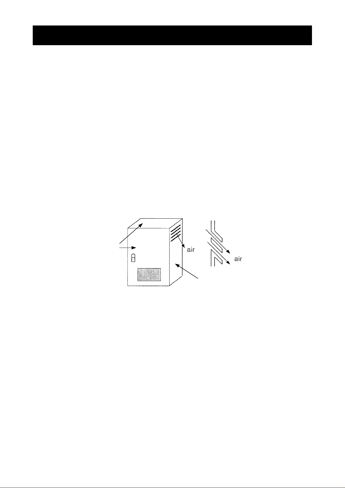
NOTE : POLLUTION DEGREE 2
The servo drives must be used environment of the degree 2.
Typical constructions that reduce the possibility of conductive pollution are;
1) The use of an unventilated enclosure
2) The use of a filtered ventilated enclosure when the ventilation is fan forced that is, ventilation is
accomplished by one or more blowers within the enclosure that provide a positive intake and
exhaust.
iii
Page 4

SAFETY
Cautions for EMC (Electromagnetic Compatibility)
It is required to satisfy the EMC directive (89/336/EEC) when using AD series servo drives in EU
country. To satisfy the EMC directive and to comply with standard (EN61800-3), the followi ng should
be kept.
WARNING
familiar with construction and operation of the equipment and the hazards involved. Failure to
observe this precaution could result in bodily injury.
1. The power supply to the drives must meet these specifications:
a. Voltage fluctuation +10%/-15% or less.
b. Voltage unbalance +/-3% or less.
c. Frequency variation +/-4% or less.
d. Voltage distortion THD = 10% or less.
2. Installation measure:
a. Use a filter designed for AD series servo drives.
3. Wiring
a. Shielded wire (screened cable) is required for motor wiring, and the length must be less
than 30 meters.
b. Separate the main circuit from the signal/process circuit wiring.
: This equipment should be installed, adjusted, and serviced by qualified personal
4. Environmental conditions – when using a filter, follow these guidelines:
a. Ambient air temperature: 0 - +55 ºC.
b. Humidity: 20 to 90% RH (non-condensing)
2
c. Vibration: 5.9 m/sec
d. Location: 1000meters or less altitude, indoors (no corrosive gas or dust)
(0.6 G) 10 – 55Hz.
iv
Page 5
SAFETY
X
Conformity to the Low Voltage Directive (LVD)
The protective enclosure is required to satisfy the Low Voltage Directive (73/23/EEC).
The drives can conform to the LVD and comply with standard (EN50178) by mounting into the
following enclosure.
1.Enclosure
The drives must be installed into a enclosure which has the protection degree of Type IP2X (See
EN60529). In addition the top surface or front surface of enclosure are easily accessible shall meet at
least the requirements of the Protective Type IP4X.
2.Protection device
A double pole disconnection device must be fitted to the incoming mains supply close to the drive.
Additionaly, a protection device meeting IEC947-1/IEC947-3 must be fitted at this point. (protection
device data shown in page vii)
IP4
IP2X with louver
v
Page 6

SAFETY
UL Warnings and Cautions Manual for AD series
This auxiliary instruction manual should be delivered to the end user.
1. Wiring Warnings for Electrical Practices and Wire Specifications
(1) ! WARNING : "Use 60/75 ºC CU wire only" or equivalent.
(2) ! WARNING: "Open Type Equipment."
(3) ! WARNING: " Suitable for use on a circuit capable or delivering not more than 10,000 rms
symmetrical amperes, 240 V maximum.
2.Tightening Torque and Wire Range
(1) ! WARNING : Tightening torque and wire range for field wiring terminals are marked
adjacent to the terminal or on the wiring diagram.
Model Name
ADAX4-R5MS 1.2 18 18
ADAX4-01MS 1.2 18 18
ADAX4-02MS 1.2 18 18
ADAX4-04MS 1.2 16 18
ADAX4-R5LS 1.2 18 18
ADAX4-01LS 1.2 18 18
ADAX4-02LS 1.2 18 18
ADAX4-04LS 1.2 18 18
ADAX4-08LS 1.2 18 18
ADAX4-10LS 1.2 16 16
ADAX4-20LS 1.2 14 14
ADAX4-30LS 1.2 12 10
ADAX4-50LS 2.0 10 10
Tightening Torque [N•m] Wire Range (AWG)
Input Output
ADAX4-01NSE 1.2 18 18
ADAX4-02NSE 1.2 18 18
ADAX4-04NSE 1.2 18 18
ADAX4-08NSE 1.2 16 18
ADAX4-15HPE 0.5~0.6 18 18
ADAX4-35HPE 0.5~0.6 14 14
ADAX4-70HPE 2.0 10 10
vi
Page 7

SAFETY
3. Fuse Size
(1) ! WARNING : Distribution fuse size marking is included in the manual to indicate that the
unit shall be connected with an UL Listed Class J fuse rated 600 V with the
current ratings as shown in the table below.
Model Name Input Phase
ADAX4-R5MS 3 3
ADAX4-01MS 3 6
ADAX4-02MS 3 10
ADAX4-04MS 3 15
ADAX4-R5LS 3 3
ADAX4-01LS 3 3
ADAX4-02LS 3 3
ADAX4-04LS 3 6
ADAX4-08LS 3 10
ADAX4-10LS 3 10
ADAX4-20LS 3 20
ADAX4-30LS 3 30
ADAX4-50LS 3 50
ADAX4-01NSE 1/3 3/3
ADAX4-02NSE 1/3 6/3
ADAX4-04NSE 1/3 10/6
ADAX4-08NSE 1/3 15/10
ADAX4-15HPE 3 10
ADAX4-35HPE 3 20
ADAX4-70HPE 3 50
Fuse [A]
4.Others
(1) ! WARNING : "Field wiring connection must be made by an UL Listed and CSA Certified
closed-loop terminal connector sized for the wire gauge involved. Connector must be fixed using the
crimp tool specified by the connector manufacturer. ", or equivalent wording included in the manual.
(2) ! WARNING : Use the transient voltage surge suppressors recognized in
UL1449.
(3) ! W ARNING : “Solid st ate motor over load protection is provided in each model.”, or equivalent.
(4) ! WARNING : “Maximum Surrounding Air Temperature 55°C.”
(5) ! WARNING : “Not incorporating Over-speed Protection.” or an equivalent statement.
vii
accordance with
Page 8

CONTENTS
Contents
CHAPTER 1 SAFETY PRECAUTIONS
1.1 Installation...................................1 − 2
1.2 Wiring..........................................1 − 3
1.3 Control and operation...................1 −4
1.4 Maintenance, inspection and ......1 − 5
part replacement
1.5 Others......................................... 1 − 5
CHAPTER 2 INTRODUCTION
2.1 Inspection upon unpacking.........2 − 2
2.1.1 Checking the product.............2 − 2
2.1.2 Instruction manual..................2 − 5
2.2 Inquiry about the Product
and Warranty ..............................2 − 5
2.2.1 Notes for making an
inquiry ....................................2 − 5
2.2.2 Product warranty....................2 − 5
2.2.3 Charged repair.......................2 − 5
2.3 Appearance and Names
of Parts .......................................2 − 6
2.4 Combination of servo amplifiers
and servo motors........................2 − 8
CHAPTER 3 INSTALLATION AND WIRING
3.1 Installation...................................3 − 2
3.1.1 Precautions on
installation..............................3 − 3
3.2 Wiring..........................................3 − 5
3.2.1 Terminals and connectors......3 − 6
3.2.2 Main circuit wiring...................3 − 8
3.2.3 Wiring for the control power
connector (TM2)
(200V class).........................3 − 21
3.2.4 Connecting the backup
battery for absolute
encoder................................3 − 22
3.2.5 Input/output signal
wiring....................................3 − 23
3.2.6 Wiring for encoder
signals..................................3 − 39
CHAPTER 4 OPERATION
4.1 Operating Method.......................4 − 2
4.1.1 Speed-control operation
by analog input.......................4 − 4
4.1.2 Speed control operation
by multistage speed...............4 − 5
4.1.3 Position control operation
by pulse train input.................4 − 6
4.2 Test Run.....................................4 − 7
4.2.1 Test run by analog input ........4 − 7
4.2.2 Test run by multistage
speed.....................................4 − 8
4.2.3 Jogging operation and teaching
operation from the digital
operator .................................4 − 9
4.2.4 Test run by using the
setup software AHF..............4 − 11
CHAPTER 5 FUNCTIONS
5.1 Terminal Functions List...............5 − 2
5.2 Input Terminal Functions.............5 − 4
5.3 Output Terminal Functions........5 − 15
5.4 Analog Input/output
Function....................................5 − 21
5.4.1 Analog Input Function...........5 − 21
5.4.2 Analog Output Function.........5 − 27
5.5 Analog Input Acceleration/
Deceleration Function...............5 − 28
5.6 Multistage Speed Function........5 − 29
5.7 Position Pulse Train Input
Function....................................5 − 31
5.8 Smoothing Function..................5 − 34
5.9 Encoder Monitor Function.........5 − 36
5.10 Adjusting the Control Gain......5 − 38
5.10.1 Basic Rules of Gain
Adjustment ........................5 − 38
5.10.2 Rigidity and Response
Setting of The Mechanical
System ..............................5 − 39
5.10.3 Adjusting The Speed
Feedback Loop..................5 − 40
5.10.4 Adjusting The Position
Feedback Loop..................5 − 41
5.1 1 Offline Auto-tuning Function...5 − 42
5.1 1.1 Offline Auto-tuning
Method...............................5 − 42
5.1 1.2 Offline Auto-tuning Using
the AD series Setup
Software AHF.....................5 − 45
5.12 Online Auto-tuning Function...5 − 47
5.12.1 Online Auto-tuning
Method...............................5 − 47
Page 9

Contents
CONTENTS
5.12.2 Online Auto-tuning Using
the Setup Software AHF ....5 − 50
5.13 Gain Change Function............5 − 51
5.13.1 Changing the Control
Gain................................... 5 − 51
5.14 Functions for Absolute
Position Encoder ....................5 − 54
5.15 Clearing the Trip Log and
Factory Settings......................5 − 58
5.16 Directions of Run of the Servo
Motor and Servo Drive............5 − 60
5.17 Speed Limit Function..............5 − 60
5.18 Fast positioning Function........5 − 61
5.19 Notch filter Function................5 − 62
CHAPTER 6 DETAILS OF PARAMETERS
6.1 Names of Digital Operator
Parts and Operating the
Digital Operator...........................6 − 2
6.1.1 Names of Digital Operator
Parts.......................................6 − 2
6.1.2 Operating the Digital
Operator.................................6 − 3
6.2 List of Functions..........................6 − 6
6.2.1 List of Monitor Functions........6 − 7
6.2.2 List of Setting Parameters......6 − 8
6.3 Details of Functions ..................6 − 14
6.3.1 Details of Monitor
Indication..............................6 − 14
6.3.2 Details of Setting
Parameters ..........................6 − 18
6.4 Control Block Diagram and
Monitors....................................6 − 48
CHAPTER 7 MAINTENANCE AND
INSPECTION
7.1 Precautions on Maintenance
and Inspection.............................7 − 2
7.1.1 Request at Maintenance
and Inspection........................7 − 2
7.1.2 Daily Inspection......................7 − 2
7.1.3 Cleaning.................................7 − 2
7.1.4 Periodic Inspection.................7 − 2
7.2 Daily Inspection and Periodic
Inspection ...................................7 − 3
7.3 Megger Test and Withstand
Volt age Test ................................7 − 4
7.4 Checking the Inverter and
Converter....................................7 − 4
7.5 Capacitor Life Curve ..................7 − 6
7.6 Battery Life for
Absolute Encoder ......................7 − 6
CHAPTER 8 SPECIFICATIONS AND
DIMENSIONS
8.1 Specification Table Standard.......8 − 2
8.2 External Dimension and
Mounting Hole
Drawing of Servo Drive...............8 − 4
CHAPTER 9 TROUBLESHOOTING
9.1 Trip Indication (Trip Log).............9 − 2
9.2 List of Protective Functions.........9 − 3
9.3 Troubleshooting..........................9 − 5
9.3.1 When a trip is not caused ......9 − 5
9.3.2 When a trip is caused ............9 − 8
CHAPTER 10 OPTIONAL FUNCTIONS
10.1 Outline of Modbus communication
option module...........................10 − 2
10.2 Wiring of Modbus-Network........10 − 3
10.3 Modbus communication
specifications ............................10 − 5
10.4 Modbus commuication
setting.......................................10 − 5
10.5 Modbus transmission
procedure................................10 − 6
10.6 List of Modbus Coil number
and Register number..............10 − 15
10.7 Teaching Function..................10 − 26
10.7.1 Name and operation of
each parts of
Teaching UNIT....................10− 26
10.7.2 Mode change operation and
operation with each mode ..10− 28
10.7.3 Other explanations .............10− 31
CHAPTER 11 APPENDIXES
11.1 Options...................................11 − 2
1 1.2 Electronic Thermal Operation
Time.....................................11 − 19
11.3 Internal Block Diagram of
Servo Drive...........................11 − 23
Page 10

CONTENTS
11.4 Example Connection with
Programmable Controller .....11 − 27
11.4.1 Main circuit connection.....11 − 27
11.4.2 Connection with Hitachi 4 axes
positioning module
EH-POS4(I/O)..................11 − 29
11.4.3 Connection with Hitachi one
axis positioning
module EH-POS(I/O)........11 − 30
11.4.4 Connection with Hitachi 4
axis positioning module
EH-POS4(I/O)...................11
11.4.5 Connection with Hitachi one
axis positioning module
EH-POS(I/O).....................11
11.4.6 Modbus connection
example.............................11
11.5 Example Connection with
peripheral equipment ...........11 − 34
11.5.1 Connection of Speed/
Torque control operation...11
− 31
− 32
− 33
− 34
Contents
Page 11

CHAPTER 1 SAFETY PRECAUTIONS
Read this manual and all of the warning sign attached to the drives carefully
before installing and operating it, and follow the instructions exactly . Keep this
manual handy for your quick reference.
1.1 Installation.................................................... 1 − 2
1.2 Wiring........................................................... 1 − 3
1.3 Control and operation ………………………... 1 − 4
1.4 Maintenance, inspection and part ............... 1 − 5
replacement
1.5 Others.......................................................... 1 − 6
1 - 1
Page 12

CHAPTER 1 SAFETY PRECAUTIONS
1.1 Installation
CAUTION
• Be sure to install the unit on flame resistant material such as metal.
Otherwise, there is a danger of fire.
• Be sure not to place anything inflammable in the vicinity.
Otherwise, there is a danger of fire.
• Do not carry unit by top cover, always carry by supporting base of unit.
There is a risk of falling and injury.
• Be sure not to let the foreign matter enter such as cut wire refuse, spatter
from welding, iron refuse, wire, dust, etc.
Otherwise, there is a danger of fire.
• Be sure to install it in a place where can bear the weight according to the
specifications in the text.
Otherwise, it may fall and there is a danger of injury.
• Be sure to install the unit on a perpendicular wall where is not subject to
vibration.
Otherwise, it may fall and there is a danger of injury.
• Be sure not to install and operate AC servo drive which is damaged or parts
of which are missing.
Otherwise, there is a danger of injury.
• Be sure to install it in a room where is not exposed to direct sunlight and is
well ventilated. Avoid environments which tend to be high in temperature,
high in humidity or to have dew condensation, as well as places with dust,
corrosive gas, explosive gas, inflammable gas, grinding-fluid mist, salt
damage, etc.
Otherwise, there is a danger of fire.
1 - 2
Page 13
1.2 Wiring
• Be sure to ground the unit.
Otherwise, there is a danger of electric shock and/or fire.
• Wiring work shall be carried out by electrical experts.
Otherwise, there is a danger of electric shock and/or fire.
• Implement wiring after checking that the power supply is off.
It might incur electric shock and/or fire.
• After installing the main body, carry out wiring.
Otherwise, there is a danger of electric shock and/or injury.
WARNING
CHAPTER 1 SAFETY PRECAUTIONS
• Make sure that the input voltage is:
Three phase 200 to 230V 50/60Hz (for models with suffix L)
Single phase 100 to 115V 50/60Hz (for models with suffix M)
Single phase 220 to 230V / Three phase 200 to 230V 50/60Hz
(for models with suffix N)
Three phase 380 to 480V 50/60Hz (for models with suffix H)
Control power supply 200 to 240V 50/60Hz (for models with suffix H)
Otherwise, there is a danger of fire.
• Be sure not to input a single phase for models with suffix H and suffix L.
Otherwise, there is a danger of fire.
• Be sure not to connect AC power supply to the output terminals(U, V, W).
Otherwise, there is a danger of injury and/or fire.
• Be sure not to connect the resistor to DC terminals (+1,+ and –) directly.
Otherwise, there is a danger of fire.
• As for motor leads, fuses and electromagnetic contactors, be sure to use the
equivalent ones with the specified capacity (rated).
Otherwise, there is a danger of fire.
• Fasten the screws with the specified fastening torque. Check so that there is
no loosening of screws.
Otherwise, there is a danger of fire.
CAUTION
• Connection to field wiring terminals must be reliably fixed having two
independent means of support. Using terminal with cable support, cable
gland or cable clamp etc.
Otherwise, there is a danger of fire.
• Be sure to connect between servo drive logic ground (L) and controller ground
when pulse train input is used by servo drive with source type logic.
Otherwise, A equipment failure will be caused.
1 - 3
Page 14

CHAPTER 1 SAFETY PRECAUTIONS
1.3 Control and operation
WARNING
• While the servo drive is energized, be sure not to touch the main terminal or
to check the signal or put on/off wire and/or connector.
Otherwise, there is a danger of electric shock.
• Be sure to turn on the input power supply after closing the terminal cover.
While being energized, be sure not to open the terminal cover.
Otherwise, there is a danger of electric shock.
• Be sure not to operate the switches with wet hands.
Otherwise, there is a danger of electric shock.
• While the servo drive is energized, be sure not to touch the servo drive
terminals even during stoppage.
Otherwise, there is a danger of electric shock.
• It may suddenly restart after the incoming power failure. Be sure not to
approach the machine. (Be sure to design the machine so that personnel
safety will be secured even if it restarts.)
Otherwise, there is a danger of injury.
• Even if the power supply is cut for a short period of time, it may restart
operation after the power supply is recovered if the operation command is
given. If it may incur danger to personnel, be sure to make a circuit so that it
will not restart after power recovery.
Otherwise, there is a danger of injury.
• After the operation command is given, if the alarm reset is conducted, it will
restart suddenly. Be sure to set the alarm reset after checking the operation
command is off.
Otherwise, there is a danger of injury.
• Be sure not to touch the inside of the energized servo drive or to put a bar
into it.
Otherwise, there is a danger of electric shock and/or fire.
1 - 4
Page 15
CHAPTER 1 SAFETY PRECAUTIONS
• Cooling fin will have high temperature. Be sure not to touch them.
Otherwise, there is a danger of getting burned.
• Install external break system if needed.
Otherwise, there is a danger of injury.
CAUTION
1.4 Maintenance, inspection and part replacement
• After a lapse of more than 10 minutes after turning off the input power supply,
perform the maintenance and inspection.
Otherwise, there is a danger of electric shock.
• Make sure that only qualified persons will perform maintenance, inspection
and part replacement. (Before starting the work, remove metallic objects
from your body (wristwatch, bracelet, etc.)
(Be sure to use tools protected with insulation.)
Otherwise, there is a danger of electric shock and/or injury.
WARNING
1.5 Others
• Never modify the unit.
Otherwise, there is a danger of electric shock and/or injury.
WARNING
1 - 5
Page 16

CHAPTER 1 SAFETY PRECAUTIONS
MEMO
1 - 6
Page 17

CHAPTER 2 INTRODUCTION
This chapter explains the checking, warranty, and names of parts of the
product that you purchased.
2.1 Inspection upon unpacking.......................... 2 − 2
2.1.1 Checking the product ............................ 2 − 2
2.1.2 Instruction m anual................................. 2 − 5
2.2 Inquiry about the Product and Warranty...... 2 − 5
2.2.1 Notes for making an inquiry................... 2 − 5
2.2.2 Product warranty................................... 2 − 5
2.2.3 Charged repair ...................................... 2 − 5
2.3 Appearance and Names of Parts................. 2 − 6
2.4 Combination of servo amplifiers
and servo motors.................................... 2 − 8
2 - 1
Page 18
CHAPTER 2 INTRODUCTION
2.1 Inspection upon unpacking
2.1.1 Checking the product
After unpacking, take out the servo drive and check the following items.
If you have any doubt or fault on the product, please contact your dealer.
(1) Make sure that there was no damage (injury, falling or dents in the body) of the product.
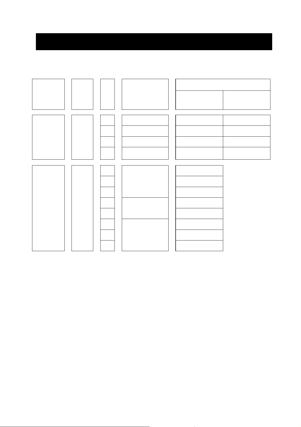
(2) After unpacking, make sure that the package contains the following articles.
ADAX4-LS/MS
Packed article
(a) Servo drive 1 unit 1 unit 1 unit 1 unit 1 unit (b) Control power
supply connector
(c) Main power circuit
/ control power
circuit connector
(d)Instruction manual 1 copy 1 copy 1 copy 1 copy 1 copy Installation manual
(e)communication
connector
ADAX4-LSMB/MSMB
50~1.5kw more than
2kW
1 piece Not
provided
Not
provided
1 piece 1 piece 1 piece 1 piece 1 piece Only ADAX4-
Not
provided Not provided 3 pieces
ADAX4-NS
ADAX4-NSMB
(200V class)
1 piece
ADAX4-HP
ADAX4-HPMB
(400V class)
1.5, 3.5kW 7kW
Not
provided
Not
provided
Not
provided
Remarks
With wire inserting jig
With B1-B2 short bar
Main power circuit : 2
Control power circuit : 1
MB
The attached manual with the servo drive is the simple one for installation, maintenance and
inspection. This detailed manual is not attached.
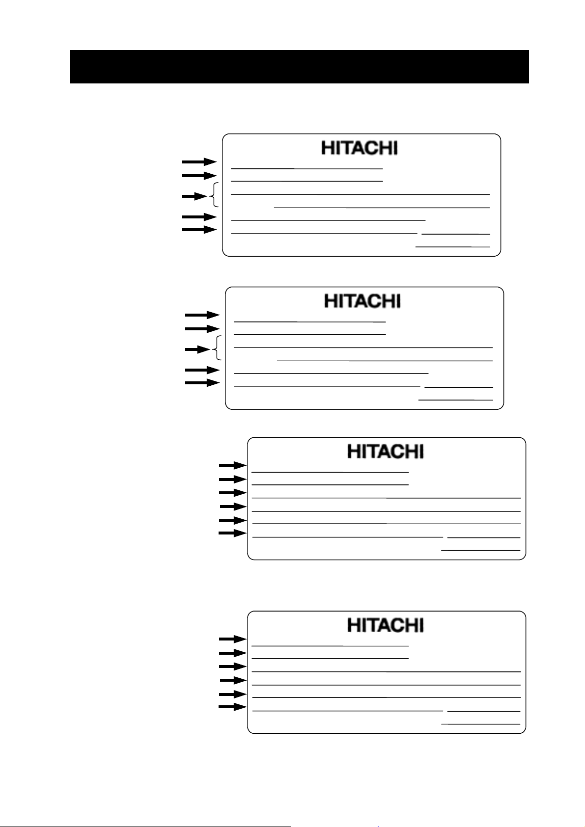
(3) Check on the specification nameplate whether the product is as ordered or not.
(a)
Specification
(b)
nameplate
(Located on the
front cover for
3-phase 400V
3.5kW and
7kW)
(c)
d)
(
HITACHI AC Servo Drives
ADAX4 Series
Instruction Manual
3-phase 400V
1.5, 3.5kW
(Without cover)
HITACHI
Specification nameplate position
(200V class and 400V 1.5kW)
(e)
(e) Only ADAX4-MB
2 - 2
Page 19
CHAPTER 2 INTRODUCTION
p
r
A
r
r
p
r
A
r
r
[200V class servo amplifiers]
Drive model
Applicable motor
maximum rated out
Input rating
Output rating
Production numbe
ut
Model :
kW
Input :
Input :
Output : 3Ph
MFG No.
Hitachi Industrial Equipment
ADAX3-02NSE
1Ph
3Ph
212U N12345 20001 0209
Systems
Co.,Ltd
0.2
220-230 2.5
200-230
230
Vmax
MADE IN JAPAN
[200V class servo amplifiers with Modbus optional board]
Drive model
Applicable motor
maximum rated out
Input rating
Output rating
Production numbe
ut
Model :
kW
Input :
Input :
Output : 3Ph
MFG No.
Hitachi Industrial Equipment
ADAX3-02NSEMB
0.2
1Ph
3Ph
220-230 2.5
200-230
230
212U N12345 20001 0209
Systems
Co.,Ltd
Vmax
[400V class servo amplifiers]
V
1.5
V
1.7
V
1.5
V
1.7
MADE IN JAPAN
50Hz
A
50Hz
A
A
Date:
NE17121
50Hz
A
50Hz
A
A
Date:
NE17121
,60Hz
,60Hz
-39
,60Hz
,60Hz
-39
Drive model
pplicable moto
maximum rated output
Control power circuit input
Main power circuit Input
Output rating
Production numbe
Model :
kW
Input(Control): 1Ph
Input(Main) : 3Ph
Output :
MFG No.
Hitachi Industrial Equipment
ADAX3-35HPE
24A N12345 20001 0209
Systems
Co.
3.5
3Ph
,Ltd
200-240 0.3
380-4801213
480
[400V class servo amplifiers with Modbus optional board]
Drive model
pplicable moto
maximum rated output
Control power circuit input
Main power circuit Input
Output rating
Production numbe
Model :
kW
Input(Control): 1Ph
Input(Main) : 3Ph
Output :
MFG No.
Hitachi Industrial Equipment
ADAX3-35HPEMB
3.5
3Ph
24A N12345 20001 0209
Systems
Co.
,Ltd
200-240 0.3
380-4801213
480
V
V
Vmax
MADE IN JAPAN
V
V
Vmax
MADE IN JAPAN
A
50Hz
50Hz
A
0 -420Hz
A
Date:
NE17609
A
50Hz
50Hz
A
0 -420Hz
A
Date:
NE17609
,60Hz
,60Hz
-2
,60Hz
,60Hz
-2
Contents of Specification Nameplate
2 - 3
Page 20
CHAPTER 2 INTRODUCTION
(4) When the 200V class servo motor with the serial incremental encoder (17bit / revolution) is
different from the specification of the standard product, connect the encoder and then perform
initialize processing. For the procedure, refer to Chapter 5, “Clearing the Trip Log and
Performing Factory-setting”.
(5) In case that you use the motor with the serial absolute encoder (17bit / revolution), Absolute
Battery Error (E90) occurs after connecting the backup battery and turning on the power
supply. Clear the trip and then clear the encoder data. For the procedure, refer to Chapter
5, “Functions for Absolute Position Encoder”, (2) Clearing the absolute position.
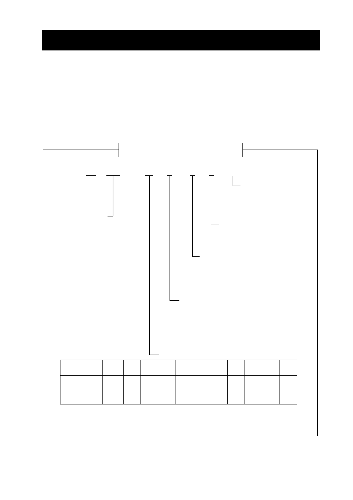
Explanation of Drive model
AD
AX4
Series name
AD : AD series
Drive name
AX4 : Programmable
function build-in
–
08 N
S
E
MB
Option
None : Standard
MB :
Modbus
I/O polarity
None:
Input…Sink/Source Output…Sink
Pulse input… insulation
Input…Sink/Source Output…Source
E:
Pulse input… no insulation
Encoder type
S:
17bit / revolution
Serial encoder
(Incremental, Absolute)
P: Wire-saving incremental encoder
Input power supply
M: Single phase 100V class
L: Three phase 200V class
N: Single / Three phase 200V class
H: Three phase 400V class
Output rating
Symbol
Rating(kW)
Voltage
(Note) Drive is becomes an article of order by combination of input power supply, Encoder type and
I/O polarity. Refer to chapter 8 for Standard models.
R5 01 02 04 08 10 15 20 35 50 70
0.05 0.1 0.2 0.4 0.8 1.0 1.5 2.0 3.5 5.0 7
M
L
-
-
M
L
N
-
M
L
N
M
L
N
L
N
-
2 - 4
-
-
-
-
-
-
L
L
L
L
L
-
-
-
-
-
-
-
-
H
-
H
-
H
Page 21

CHAPTER 2 INSTRUCTION
2.1.2 Instruction manual
This instruction manual explains the detail of the Hitachi AD series servo.
Please read this manual thoroughly to operate the product correctly before operating it. Keep the
manual in custody with care.
When using option products related to this servo drive, read the instruction manuals for the related
products thoroughly.
2.2 Inquiry about the Product and Warranty
2.2.1 Notes for making an inquiry
If you have to make an inquiry about product damage, doubt, failure, etc., inform the dealer of the
following items.
(1) Servo drive type a nd form (model No.)
(2) Production number (MFG. No.)
(3) Date of purchase
(4) Contents of your inquiry
- Damage position, status, etc.
- Doubtful item, contents, etc.
2.2.2 Product warranty
The product warranty period shall be one year after purchase.
In the following cases, however , the product is out of the warranty range and shall be repa ired with
charge even within the warranty period.
(1) The failure is due to an operation error or improper repair or modification.
(2) The failure is due to any other reason that is not related to your purchased product.
(3) The product was operated over the specification value rang e.
(4) The failure is due to a natural calamity, disaster, or secondary disaster.
The warranty herein referred to means the warranty of the delivered product proper. Any damage
induced by a failure of the delivered product shall be excluded.
2.2.3 Charged repair
After the lapse of the warranty period (one year), any investigation and repair shall be performed
with charge. In the warranty period, repair or investigation that is out of the above warranty range
shall be undertaken with charge.
For asking for a charged repair, contact with the dealer.
2 - 5
Page 22
CHAPTER 2 INSTRUCTION
r
r
A
r
r
A
a PC
r
A
r
r
A
r
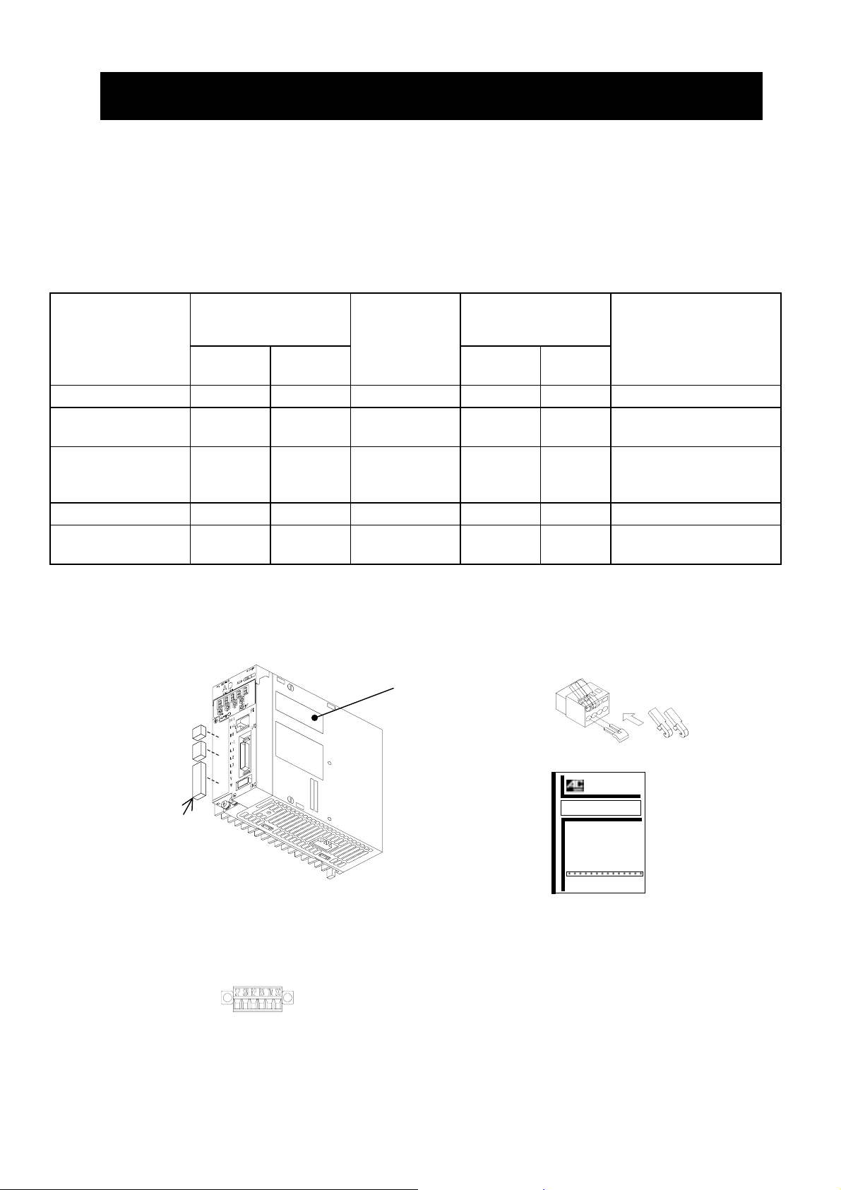
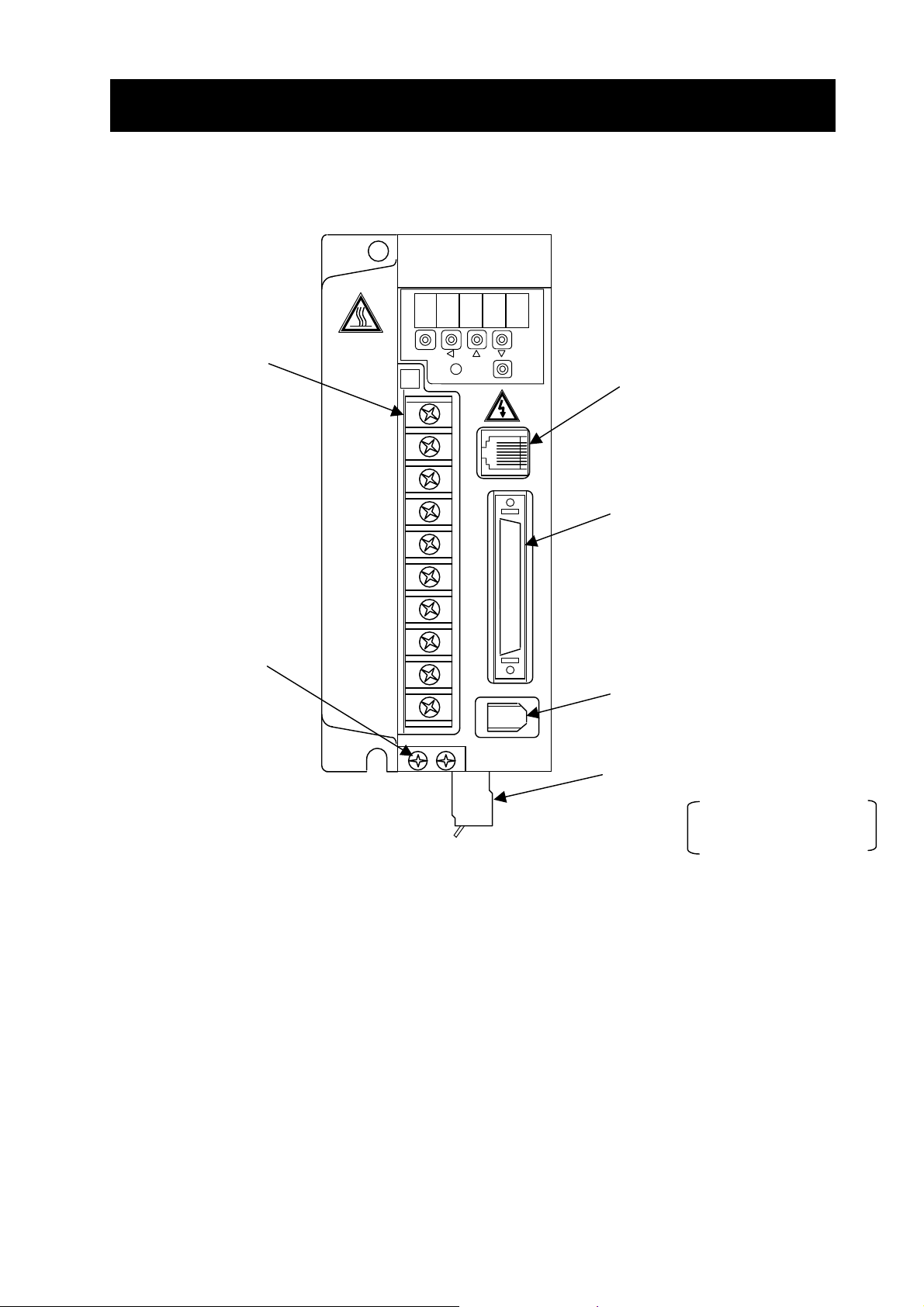
2.3 Appearance and Names of Parts
(The following drawings describe 200V class servo without optional board.)
Battery holde
Houses the backup battery when
the absolute encoder is used.
Panel display unit
Used to indicate the servo drive
condition or parameter setting by
using a 5-digit 7-segment LED.
Charge lamp
Lights up when the main circuit
power supply is turned on. While
the electric charge remains on the
main circuit capacitor after the
power supply is turned off, this
lamp continues to light. Do not
touch the servo drive during
lighting.
Main circuit terminal block (TM1)
Connection terminals with the main circuit
power supply, external regenerative
resistor, and motor power cable.
This terminal block is covered with a cover.
Connector for connecting a PC
(PC)
Battery housing cove
cover for the battery holder.
Battery connecto
Used to connect the backup
battery for the absolute
encoder.
Digital operato
Used to set parameters.
connector for communication with
.
Ground terminal
Used for protection against an
electric shock.
Exhaust
air
Input/output signal connecto
(I/O)
connector for command input
signals and sequencer input signals.
Specification nameplate
Used to indicate the servo
drive type and form and
ratings.
Encoder connecto
Used to connect the encoder of
the servo motor.
Control power supply connecto
(TM2)
connector for connecting the
control power supply.
B1-B2 short ba
Be sure to connect this
short bar when using the
internal braking resistor.
(ENC)
Intake air
2 - 6
Page 23
CHAPTER 2 INSTRUCTION
t
2.4 Combination of servo amplifiers and servo motors
The applicable combination of servo amplifiers and servo motors is shown in the following table.
Phase /
Volt age
for main
power
circuit
Single-phase
220~230V
/3-phase
200~230V
3-phase
380~480V
Rated
speed
3000
-1
(min
2000
-1
(min
Outpu
(kW)
0.1
0.2
)
0.4
0.7
5
Servo amplifier
Model code
ADAX4-01NSE(MB)
ADAX4-02NSE(MB)
ADAX4-04NSE(MB)
ADAX4-08NSE(MB)
— ADMA-01SA
— ADMA-02SA
— ADMA-04SA
— ADMA-08SA
0.5 — ADMG-05HP
1.0 — ADMG-10HP
ADAX4-15HPE(MB)
1.5
2.0 — ADMG-20HP
)
3.5
ADAX4-35HPE(MB)
Note 2)
— ADMG-15HP
Note 2)
— ADMG-35HP
4.5 — ADMG-45HP
5.5 — ADMG-55HP
ADAX4-70HPE(MB)
7.0
Note 2)
— ADMG-70HP
Applicable servo motor
With
Incremental
encoder
With
Absolute
encoder
ADMA-01SF
ADMA-02SF
ADMA-04SF
ADMA-08SF
Note 1) ADAX4 describes the standard high performance type, and ADAX3 describe
the programmable function built-in type.
Note 2) Single-phase 200 ~ 240V is needed for the control power circuit. Do not supply 3-phase
2 - 7
Page 24

MEMO
2 - 8
Page 25

CHAPTER 3 INSTALLATION AND WIRING
This chapter explains the procedure for installing this product, main circuit
wiring, and input/output signal wiring. Typical connection examples are
shown.
3.1 Installation ................................................... 3 − 2
3.1.1 Precautions on installation..................... 3 − 3
3.2 Wiring .......................................................... 3 − 5
3.2.1 Terminals and connectors...................... 3 − 6
3.2.2 Main circuit wiring.................................. 3 − 9
3.2.3 Wiring for the control power
connector (TM2) (200V class).............. 3 − 21
3.2.4 Connecting the backup
battery for absolute encoder.................. 3 − 22
3.2.5 Input/output signal wiring....................... 3 − 23
3.2.6 Wiring for encoder signals..................... 3 − 39
3 − 1
Page 26

CHAPTER 3 INSTALLATION AND WIRING
3.1 Installation
CAUTION
• Be sure to install the unit on flame resistant material such as metal.
Otherwise, there is a danger of fire.
• Be sure not to place anything inflammable in the vicinity.
Otherwise, there is a danger of fire.
• Do not carry unit by top cover, always carry by supporting base of unit.
There is a risk of falling and injury.
• Be sure not to let the foreign matter enter such as cut wire refuse, spatter from welding, iron
refuse, wire, dust, etc.
Otherwise, there is a danger of fire.
• Be sure to install it in a place which can bear the weight according to the specifications in the
text.
Otherwise, it may fall and there is a danger of injury.
• Be sure to install the unit on a perpendicular wall which is not subject to vibration.
Otherwise, it may fall and there is a danger of injury.
• Be sure not to install and operate AC servo drive which is damaged or parts of which are
missing.
Otherwise, there is a danger of injury.
• Be sure to install it in a room which is not exposed to direct sunlight and is well ventilated.
Avoid environments which tend to be high in temperature, high in humidity or to have dew
condensation, as well as places with dust, corrosive gas, explosive gas, inflammable gas,
grinding-fluid mist, salt damage, etc.
Otherwise, there is a danger of fire.
A failure will be caused.
• Be sure to connect between servo drive logic ground (L) and controller ground when pulse
train input is used by servo drive with source type logic.
Otherwise, A equipment failure will be caused.
3 − 2
Page 27

CHAPTER 3 INSTALLATION AND WIRING
3.1.1 Precautions on installation
1) Precaution at transportation
The servo drive employs plastic parts. Handle it so that these plastic p arts may not be damaged.
In particular, do not carry the servo drive in such a way that force is applied to only the front
surface cover and the terminal block cover. Falling may be caused.
If any part is damaged or missing, do not install and operate the servo drive.
2) Install the servo drive on an incombustible (metal) surface.
The servo drive goes to a high temperature. Install the servo drive on an incombustible vertical
metal wall surface so as to avoid a fire.
Ensure an enough space around the installation place. In particular, if there is any heat
generating device (braking resistor, reactor, etc.), keep the servo drive away from such a
material.
Ensure an enough space so
Air flow
Servo
drive
that the upper/lower wiring
ducts may not prevent the
cooling air from flowing.
Wall
3) Precaution about the ambient temperature
The ambient temperature in the installation place should not exceed the allowable operating
temperature range (0 to 55°C) described in the standard specification.
Measure the ambient temperature at an about 50 mm position away from the lower center of the
servo drive body, and make sure that it is within the allowable operating temperature range.
Operating the servo drive over the allowable operating temperature range may lead to its shorter
life (especially, the life of the capacitor) or damage.
4) Do not install the servo drive in a high-temperature and high-humidity place that may easily
cause condensation.
Operate the servo drive within the allowable operating humidity range (20 to 90%RH) described
in the standard specification. In particular, operate it in a place free from condensation.
If water-drops are attached inside the servo drive by condensation, the section between
electronic parts is shorted, resulting in a failure.
Avoid installing the servo drive in a place that is exposed to direct sunlight.
5) Precaution about the installing environment
Do not install the servo drive in a place where there is dust, corrosive gas, explosive gas,
combustible gas, grinding lubricant mist, or injury from salt. Admitting foreign substances or dust
inside the servo drive will result in a failure.
Therefore, if the servo drive must be operated in very dusty place, for example, house it in a
sealed type box.
3 − 3
Page 28
CHAPTER 3 INSTALLATION AND WIRING
6) Precaution about the installing method and direction
Install the servo drive on a mounting surface that can withstand its weight, firmly and vertically
without any screw or bolt looseness.
If the servo drive is not installed vertically on the wall surface, it may lower the cooling capacity
with a result of trip or damage.
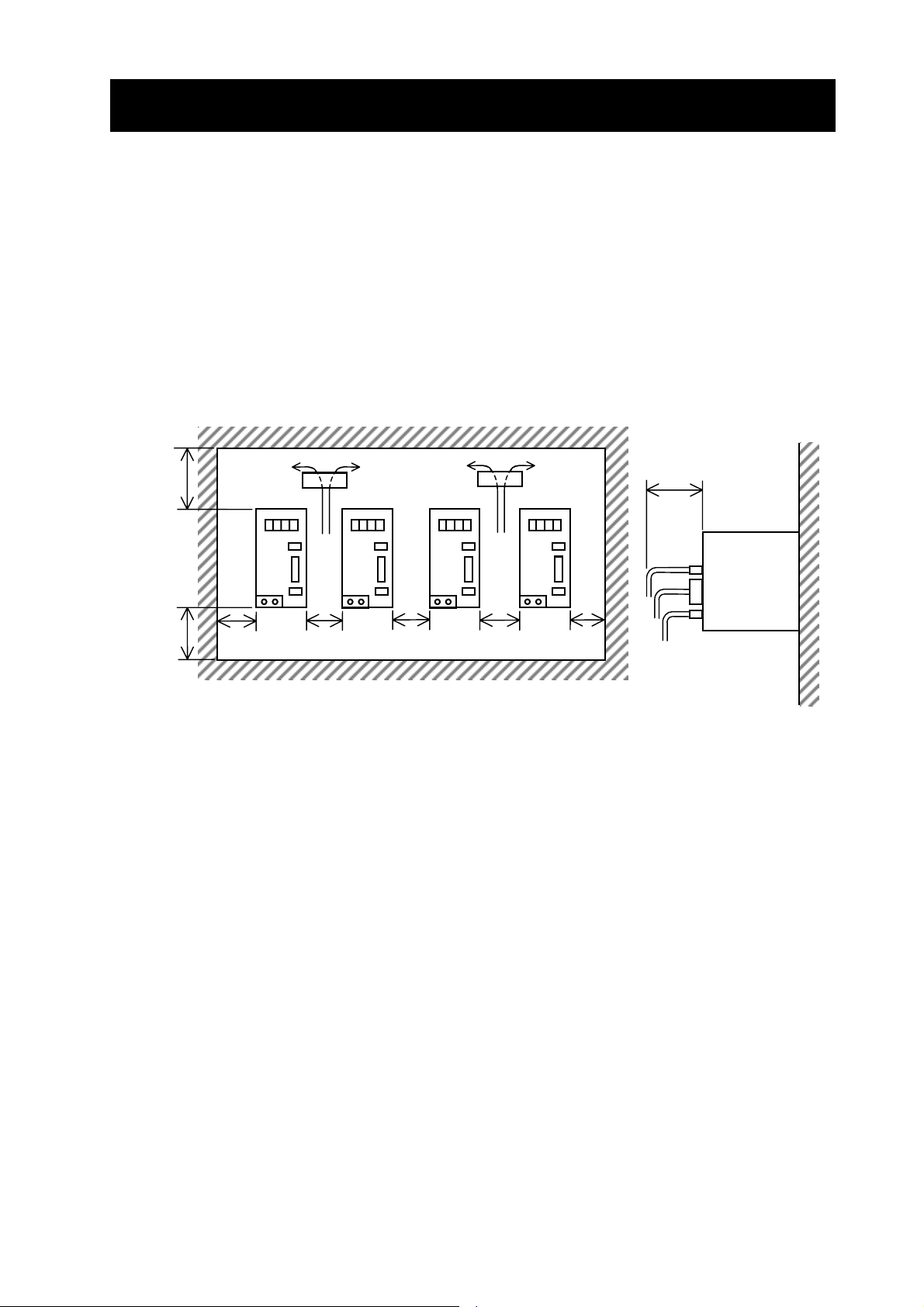
7) Precaution for housing servo drives in a box
When multiple servo drives are housed in a box and ventilation fans are equipped in the box,
provide the fans in the following way so as to make the ambient temperature of each servo drive
uniform.
100 mm
or more
Fan Fan
75 mm or more
Servo drive
100 mm
Wiring space of
or more
40 mm
or more
10 mm
or more
10 mm
or more
10 mm
or more
40 mm
or more
In the case of boxes arranged in a row , inst all them at 40 mm or more from the wall surfaces with a
space of 10 mm or more between servo drives and a clearance of 100 mm or more from the top or
bottom.
3 − 4
Page 29
CHAPTER 3 INSTALLATION AND WIRING
3.2 Wiring
WARNING
• Be sure to ground the unit.
Otherwise, there is a danger of electric shock and/or fire.
• Wiring work shall be carried out by electrical experts.
Otherwise, there is a danger of electric shock and/or fire.
• Implement wiring after checking that the power supply is off.
It might incur electric shock and/or fire.
• After installing the main body, carry out wiring.
Otherwise, there is a danger of electric shock and/or injury.
CAUTION
• Make sure that the input voltage is:
Three phase 200 to 230V 50/60Hz (for models with suffix L)
Single phase 100 to 115V 50/60Hz (for models with suffix M)
Single phase 220 to 230V / Three phase 200 to 230V 50/60Hz (for models with suffix N)
Three phase 380 to 480V 50/60Hz (for models with suffix H)
Control power supply 200 to 240V 50/60Hz (for models with suffix H)
Otherwise, there is a danger of fire.
• Be sure not to input a single phase for models with suffix H.
Otherwise, there is a danger of fire.
• Be sure not to connect AC power supply to the output terminals(U, V, W).
Otherwise, there is a danger of injury and/or fire.
• Be sure not to connect the resistor to DC terminals (+1,+ and –) directly.
Otherwise, there is a danger of fire.
• As for motor leads, fuses and electromagnetic contactors, be sure to use the equivalent ones
with the specified capacity (rated).
Otherwise, there is a danger of fire.
• Fasten the screws with the specified fastening torque. Check so that there is no loosening of
screws.
Otherwise, there is a danger of fire.
• Connection to field wiring terminals must be reliably fixed having two independent means of
support. Using terminal with cable support, cable gland or cable clamp etc.
Otherwise, there is a danger of fire.
• Be sure to connect between the servo drive logic common and master controller logic
common when using pulse count input on source type logic.
Otherwise, there is a danger of equipment failure.
3 − 5
Page 30
A
CHAPTER 3 INSTALLATION AND WIRING
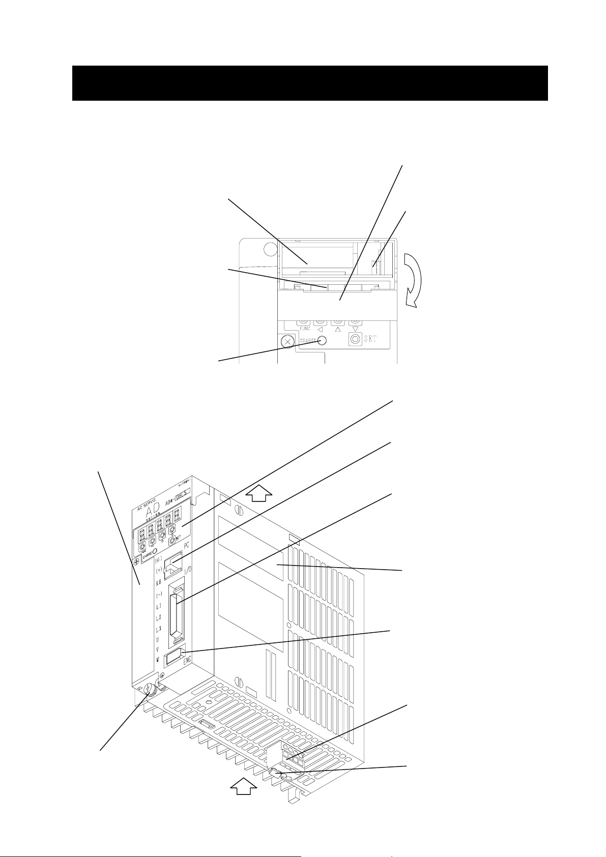
3.2.1 Terminals and connectors
(1) 200V class [less or equal 1.5kW(ADAX4-LS(MB) )]
[less or equal 750W(ADAX4-NS(MB)
)]
Main circuit
terminals (TM1)
Grounding
terminal
C SERVO
AD
series
FUNC
CHARGE
HITACHI
AD*-04NSE
SET
PC connecting
connector (PC)
Input/output signal
connector (I/O)
Encoder (sensor)
connector (ENC)
Control power
connector (TM2)
This figure is without
optional board
3 − 6
Page 31

A
CHAPTER 3 INSTALLATION AND WIRING
(2)200V class [greater or equal 2kW]
C SERVO
AD
series
HITACHI
AD*-20LS
Main circuit
terminals (TM1)
Grounding
terminal
2 screws
for 2kW to 3kW
FUNC
CHARGE
SET
PC connecting
connector (PC)
Input/output signal
connector (I/O)
Encoder (sensor)
connector (ENC)
3screws
for 5kW
Note 1) 5kW drive is a different appearance.
3 − 7
This figure is without
optional board
Page 32

A
CHAPTER 3 INSTALLATION AND WIRING
(3) 400V class
Note1)
Note2)
Control power
Note1)
Main circuit
connector 1
Note1)
Main circuit
connector 2
200~240V
C SERVO
AD
series
FUNC
CHARGE
HITACHI
AD*-15HPE
SET
PC connecting
connector (PC)
Input/output signal
connector (I/O)
Encoder (sensor)
connector (ENC)
Grounding
terminal
2 screws
for 1.5 to
3.5kW
This figure is without
optional board
3screws
for 7kW
Note 1) 3.5 and 7kW drive is a different appearance.
For 7kW, the control power and main circuit connectors are a terminal block.
Note 2) The input voltage to the control power connector is AC 200 to 240V.
Do not input the main power supply voltage to the control power connector.
3 − 8
Page 33

* 1
CHAPTER 3 INSTALLATION AND WIRING
3.2.2 Main circuit wiring
(1) Terminal connection diagram
a) 200V class
Short bar
(DC reactor connecting terminal)
Regenerative braking resistor
(option)
Note 1)
Power supply
Three-phase
AC 200 to 230 V
/ single-phase
AC 220 to 230 V
/ single-phase
AC 100 to 115 V
Note 3)
For using an external regenerative
braking resistor, disconnect the B1-B2
short bar.
FUSE
MC
TM1
(+)1
(+)
RB
(-)
L1
L2
L3
TM2
L1C
L2C
B1
B2
AD
servo drive
I/O
3 series
CNBT
TM1
ENC
Note 2)
Battery
PC
W
U
V
PC for setting and
Servo
motor
*
Encoder
7 bits serial
encoder
monitoring
Master
controller
Note 1: For single-phase 100 to 115 V AC and single-phase 220 to 230 V AC,
connect only L1 and L2. (For three phase connect L1, L2 and L3.)
Note 2: The battery is used only for the absolute encoder.
Note 3: The regenerative braking resistor is built in the model of…
L series class 200 V, 400W to 5kW.
M series class 100 V, 200W and 400 W
N series class 200 V, 400W and 750 W
3 − 9
Page 34

*
r
CHAPTER 3 INSTALLATION AND WIRING
b) 400V class
Short bar
(DC reactor connecting terminal)
Regenerative braking resistor
(option)
For using an external regenerative
braking resistor, disconnect the B1-RB
short bar.
Note 1)
Power supply
Three-phase
AC 380
to 480 V
FUSE
Note 1)
Transforme
T
MC
single-phase
200 to 240 V
Note 1)
(+)1
(+)
RB
B1
(-)
L1
L2
L3
L1C
L2C
AD
3 series
servo drive
ENC
PC
W
U
V
Servo
motor
*
Encoder
Incremental
encoder
I/O
Master
controller
PC for setting and
monitoring
Note 1: Connect three phase 380 to 480 V to L1, L2 and L3, and single phase 200 to 240 V to
L1C and L2C. Do not input 380 to 480 V to L1C and L2C. Be sure to be the secondary
voltage 200 to 240 V when the transformer is used.
3 − 10
Page 35

(+)
(+)
(–)
(+)
(+)
(–)
r
)
r
CHAPTER 3 INSTALLATION AND WIRING
(2) Terminal assignment
Type
200V class less or equal 1.5kW
Terminal
name
Main circuit
terminals
(TM1)
Grounding
terminal
Control
power
connector
(TM2)
Terminal assignment
Short
bar
1
RB
DC reactor connecting terminal
(Shorted in the unused status)
External braking resisto
DC power supply input
L1
L2
Main power supply input
L3
U
V
Motor connection
W
Grounding
Short
bar
B1
B2
L1C
Short terminal for internal braking
resistor (Open when the external
resistor is used)
Control power supply inputControl power supply input
L2C
Note: The figure shows a view of the servo drive seen
from the lower side. Refer to 3.2.3 “Wiring for
the control terminal”.
Termina
l screw
size
M4 8.1
M4
Applicable cable
size: 0.5 mm
2.0 mm
2
Termina
l width
(mm)
–
2
to
2 to 3 kW
200V class
5 kW
200V class
Main circuit
and control
power
connectors
Grounding
terminal
Main circuit
and control
power
terminals
Grounding
terminal
Short
bar
or
wire
L1C
L2C
1
B1
RB
L1
L2
L3
U
V
W
Control power supply input
connecting terminal
DC reactor connecting terminal
(Shorted in the unused status)
Short terminal for internal braking
resistor (Open when the external
resistor is used)
External braking resisto
DC power supply input
Main power supply input
Motor connection
Grounding(2 to 3kW: 2screws,
5kW: 3screws
M3
M4
M5 13
M5
–
–
–
3 − 11
Page 36

(+)
(+)RB(–)
)
r
CHAPTER 3 INSTALLATION AND WIRING
Type
400V class
1.5 to 3.5 kW
7 kW
400V class
Terminal
name
Main circuit
and control
power
connectors
Grounding
terminal
Main circuit
and control
power
terminals
Grounding
terminal
Short
bar
or
wire
Terminal assignment
L1C
L2C
1
B1
L1
L2
L3
U
V
W
Control power supply input
connecting terminal
DC reactor connecting terminal
(Shorted in the unused status)
Short terminal for internal braking
resistor (Open when the external
resistor is used)
External braking resisto
DC power supply input
Main power supply input
Motor connection
Grounding(1.5, 3.5kW: 2screws,
7kW: 3screws
Termina
l screw
size
M3
M4
M5 13
M5
Terminal
width
(mm)
–
–
–
CAUTION
1. For the connectors, perform wiring after removing them from the servo drive.
Otherwise, the servo drive way be broken.
2. When inserting the cable, take care not to bring the core whisker into contact with the
other terminal.
The servo drive may be broken.
3. If the cable core has not enough contact for any reason, strip it again and them connect
the cable.
The servo drive may be broken.
(2-1) 400V class main circuit and control power connectors
The front terminal of the servo drive separates as follows.
Model
200V class
1.5kW 3.5kW 7kW
Terminal Terminal Connector Connector Terminal
The connectors of the front main circuit and control power are attached to the servo drive.
The specification of the connectors of 400V class is shown in the following table.
400V class
ADAX4-HP(MB)
3 − 12
Page 37

CHAPTER 3 INSTALLATION AND WIRING
Specification of connectors
Model ADAX4-15HPE(1.5kW) ADAX54-35HPE(3.5kW)
Spec.
Connector
name
Control power
connector
(L1C, L2C)
Main circuit
connector 1
Connector model Assignment Connector model Assignment
Model:MSTB2.5/2
-ST-5.08
Pin No. :2P
Pin pitch:5.08mm
Wire size:1.25 -
2.5mm2/AWG16 - 12
Manufacture:
PHOENIX CONTACT
GMBH & CO.
L1C L2C +1 + B1 RB
Model:PC4/2
-STF-7.62
Pin No. :2P
Pin pitch:7.62mm
Wire size:1.25 -
4mm2/AWG16 - 10
Manufacture:
PHOENIX CONTACT
GMBH & CO.
L1C L2C
Note1)
Note1)
Model:MSTB2.5/4
-ST-5.08
Pin No. :4P
Pin pitch:5.08mm
Wire size:1.25 -
2
2.5mm
/AWG16 - 12
Manufacture:
PHOENIX CONTACT
GMBH & CO.
Model:PC4/5
-STF-7.62
Pin No. :5P
Pin pitch:7.62mm
Wire size:1.25 -
4mm2/AWG16 - 10
Manufacture:
PHOENIX CONTACT
GMBH & CO.
+1 + B1 RB -
-
L1
L2
L3
U
V
W
Note2)
Model:PC4/6
-STF-7.62
Pin No. :6P
Pin pitch:7.62mm
Wire size:1.25 -
2
/AWG16 - 10
4mm
Manufacture:
PHOENIX CONTACT
GMBH & CO.
Main circuit
connector 2
Model:GMSTB2.5/7
-ST-7.62
Pin No. :7P
Pin pitch:7.62mm
Wire size:1.25 -
2
2.5mm
/AWG16 - 12
Manufacture:
PHOENIX CONTACT
GMBH & CO.
Cover
Note1) Short bars or wires are connected between +1 and +, B1 and RB.
Do not remove them except for the optional use.
Note2) This cove prevents a faulty wiring.
When (-) terminal is used, remove it.
L1
L2
L3
U V W
3 − 13
Page 38

CHAPTER 3 INSTALLATION AND WIRING
(2-2) 400V class cable terminal treatment for connectors
Strip the cable cover as follows. Then the cable can be used as it is.
7mm
(2-3) Connecting method
Insert the core the cable in the opening of the connector. Tighten the terminal screws with
the specified torque. Insufficient tightening way result in a short cicuit or fire. Make sure not
to remove the cable by pulling. For 3.5kW, tighten the screws of both sides of the connector
after connecting it.
M3 screw
Fixing screw
Fixing screw
Fixing screw
M3 screw
Fixing screw
Connection procedure
3 − 14
Page 39

CHAPTER 3 INSTALLATION AND WIRING
(3) Precautions on wiring
Before starting wiring, make sure that the charge lamp is completely extinguished. Take care
about the capacitor that is charged at a high voltage. In 10 minutes or more after shutting off
the power supply, check with a tester that no residual voltage exists between (+) and (–) on
the main circuit terminal block, and then start the wiring work.
(3-1)Main power supply input connecting terminal (L1, L2, L3)
- Use fuses for circuit (wiring) protection between the power supply and the main power
supply terminal (L1, L2, or L3).
- Connect an electromagnetic contactor that shuts off the power supply of the servo drive
to prevent a failure or accident from spreading when the protective function of the servo
drive is actuated.
- Do not start or stop the servo drive by turning on or off each electromagnetic contactor
provided on the primary side and secondary side of the servo drive.
- Do not input a single phase to the main power supply input of 400V class servo drive
(AD*3-HPE).
- In the following cases, the converter module may be damaged.
The unbalance of power supply voltage is 3% or more.
The power supply capacity is 10 times as large as the servo drive capacity, or 500 kVA or
more.
A sudden power supply change occurs.
(Example) Multiple servo drives are interconnection with a short bus.
- Turn on and off the power supply, at least, at intervals of 5 minutes per operation.
Otherwise, the servo drive may be damaged.
(3-2)Motor cable connecting terminal (U, V, W)
- Perform wiring by using a thicker cable than applicable cable in order to suppress a
voltage drop.
(3-3)DC reactor connecting terminal ((+) 1, (+))
- This terminal is used to connect the DC reactor (option) for improvem ent of power factor.
A short bar or wire is connected between terminals (+) 1 and (+) at delivery from the
factory. When connecting the DC reactor, disconnect it bar beforehand. When the DC
reactor is not used, do not remove it.
(3-4)External braking resistor connecting terminal ((+), RB))
- The regenerative braking circuit and the braking resistor are built-in the servo drive (But
200V class 100W, 200W not provided it). To enhance the braking capacity, connect the
optional external braking resistor to this terminal. For using the external braking resistor ,
disconnect the short bar or wire between the terminals (B1 and B2 or RB) for internal
braking resistor. The wiring length should be 5 m or less and perform wiring by twisting
two wires without making inductance.
- Install a resistor exceeding the resistance value R
shown in the following table.
BRmin
Installing a resistor not exceeding the resistance value shown in the table will cause
damage to the regenerative braking circuit.
3 − 15
Page 40

CHAPTER 3 INSTALLATION AND WIRING
Servo drive capacity Built-in R
50W Not provided 35Ω
Single-phase
100V
(M)
100W Not provided 35Ω
200W 30 W 75Ω (9 W, 1.0%) 25Ω
400W 50 W 20Ω (17 W, 1.0%) 17Ω
50W,100W Not provided 100Ω
200W Not provided 100Ω
400W 30 W 75Ω (15 W, 0.5%) 50Ω
Three-phase
200V
750W 50 W 50Ω (15 W, 0.5%) 40Ω
1kW,1.5kW 70 W 25Ω (27 W, 0.5%) 25Ω
(L)
2kW 120 W 10Ω (70 W, 0.5%) 10Ω
3kW 120 W 10Ω (70 W, 0.5%) 10Ω
5kW 180 W 6Ω (120 W, 0.5%) 6Ω
Single-phase/
Three-phase
200 V
(N)
Three-phase
400 V
(H)
100 W Not provided 100Ω
200 W Not provided 100Ω
400 W 50 W 50Ω (15 W, 0.5%) 50Ω
750 W 50 W 50Ω (15 W, 0.5%) 40Ω
1.5 kW 50 W 100Ω (27 W, 0.5%) 100Ω
3.5 kW 120 W 50Ω (70 W, 0.5%) 50Ω
7 kW 180 W 25Ω (120 W, 0.5%) 25Ω
BR
Minimum resistance
value R
BRmin
Note: The power of the built-in braking resistor RBR is the nominal power value. The values
in parentheses are the available average power (W) and the allowable operating ratio
(%).
(3-5)DC power supply input connecting terminal ((+), (–))
- To supply the DC power from an external converter, this terminal is used to connect the
DC power supply. The DC power supply voltage should be 270 V DC to 310 V DC for
200V class, 510V DC to 650V DC for 400V class (+10%, –15%). Use a power supply of
enough capacity.
- When supplying the DC power supply, do not connect anything to the main power supply
input connecting terminals (L1, L2, L3).
- When supplying the DC power supply, set the PN power supply (FA-07) to Pn. If this is
not set, a momentary power failure will be detected by mistake for 200 V class servo
drive.
(3-6)Control power supply input connecting terminal (L1C, L2C)
- This servo drive has to supply the control power supply apart from the main circuit power
supply. Be sure to connect the single-phase AC power supply to the control power
supply input terminal (L1C, L2C). For this power supply, use a fuse for circuit (wiring)
protection.
- The control power supply of 400V class servo drive (AD*3-HPE) is AC 200 – 240 V.
- Turn on and off the power supply, at least, at intervals of 5 minutes per operation.
Otherwise, the servo drive may be damaged.
3 − 16
Page 41

CHAPTER 3 INSTALLATION AND WIRING
(3-7)Grounding connecting terminal ( ) )
- For prevention ag ainst an electric shock, be sure to be grounded the servo drive and the
servo motor as specified.
- Use a larger size than the applicable wire as the grounding conductor. It should be as
short as possible.
Note 1: For wiring to the terminals, use a solderless terminal conforming to the terminal screw
size and terminal width. If a too wide solderless terminal width is used, this connection
may not be made. In particular, take care about the terminal width in the following
cases.
-2 mm
-8 mm
Note 2: Separate the servo drive signal input cable or encoder cable from the main circuit power
cable or control power cable 30 cm or more from each other. If they must intersect each
other, cause them to intersect at a right angle as shown in the following figure. If they
are not separated enough, a malfunction may be caused.
2
or more cable is connected to the main circuit terminals of 200 V class.
2
or more cable is connected to the main circuit terminals of 400 V class 7kW.
30 cm or more
Main circuit power cable
(L1, L2, L3, U, V, W, (+), (+)1, RB)
Control power supply cable
(L1C, L2C)
Intersect at a right angle.
Signal input or encoder cable
3 − 17
Page 42

r
A
A
C
r
r
CHAPTER 3 INSTALLATION AND WIRING
(4) Wiring equipment, options
Name Model Function
1 Setup software AHF AHF-P01,P02 Setting,monitoring and graphic display by PC
2 Enco der cable ADCE-C---S,HP -C:standard type, -CH:high flexure life type
Power cable
3
(with or without brake)
4 Command cable ADCC-03 Cable with I/O connector
5 PC connecting cable ADCH-AT2 Cable with DOS/V PC connector(D-SUB 9P)
6 Connector set for I/O ADCC-CON Connector and its cover
Lithium battery
7
(for absolute encorder)
ADABS-BT
8 Terminal block ADCC-TM
9 Above adapter cable ADCC-T01,T02
10 Input –side rea cto r ALI- Power factor improvement, power cooperation
1 1 DC reactor DCL- Power factor improvement
12 Noise filter NF- EMC noise filter
Radio noise filter
13
(zero-phase reactor)
ZCL-B40,B75
ZCL-A
14 Input-side noise filter CFI-L,-H Reduction for radiating noise
External braking
15
resistor
RB,JRB---,SRB--- Braking power capacity improvement
16 Noise filter SUP-E1H-EP EMC noise filter for 400 V class control power
17
Teaching unit ADOPE-SR Teaching unit for optional board
Teaching unit
18
connecting cable
ADICS-1/ADICS-3
Motor cable (Prepared by customer)
Encoder data are kept by battery at control power
off for the absolute encoder use.
Terminal connection adapter for I/O connector
with 1m or 2m cable
Reduction for radiating noise
Cable with Teaching unit connector.
This is necessity using teaching unit.
10.Input
side
reactor
Power supply
Power supply
for brake
11.DC reactor
Earth
leakage
breaker
15.External
braking
resistor
Electromagnetic
contactor
12.Noise
filter
Prepared by
customer
13.Radio
noise filter
14.Input-
side noise
filter
16.Noise
filter
7.Lithum
battery
Servo drive
AC SERVO
series
FUN
CHARGE
3.Powe
cable
3.Brake cable
3 − 18
D
(+1)
+
(
RB
-
)
(
L1
L2
L3
U
V
W
D*-08LS
)
SET
PC
I/O
ENC
18.Teaching
unit
connecting
cable
5.PC
connecting
cable
6.Connector
set for I/O
9.Adapter cable
13.Radio
noise filter
17.Teaching unit
2.Encode
cable
1.Setup software
AHF
4.Command
cable
8.Terminal block
Servo moto
Master
DOS/V PC
Page 43

CHAPTER 3 INSTALLATION AND WIRING
5) Recommended wire size and wiring equipment
- For the wire size and wiring equipment to be used for wiring to the servo drive, refer to the
following table.
- For safety, use fuses.
- As the cable, use a 75°C copper electric cable.
- When the wiring length exceeds 20 m, the power cable m ust be larger.
- Tighten the terminal screw with the specified tightening torque. Insufficient tightening may result
in a short circuit or fire.
(Tightening torque)
For 1.5kW, 3.5kW (M3 screw): 0.6 N.m(max.0.66N.m)
For 7kW (M5 screw): 2.0 N.m(max.2.2N.m)
For up to 750W (M4 screw): 1.2 N.m(max.1.35N.m)
Voltage
class
Single
phase
100V
class
Three
phase
200V
class
Single
/ Three
phase
200V
class
Three
phase
400V
class
Main circuit power
MotorkWServo drive
model
0.05 ADAX4-R5MS* AWG 18 (1.25mm2) AWG 18 (1.25mm2) AWG 20 (0.5mm2) 5A H10C
0.1 ADAX4-01MS* AWG 18 (1.25mm2) AWG 18 (1.25mm2) AWG 20 (0.5mm2) 5A H10C
0.2 ADAX4-02MS* AWG 18 (1.25mm2) AWG 18 (1.25mm2) AWG 20 (0.5mm2) 10A H10C
0.4 ADAX4-04MS* AWG 18 (1.25mm2) AWG 18 (1.25mm2) AWG 20 (0.5mm2) 15A H10C
0.05 ADAX4-R5LS* AWG 18 (1.25mm2) AWG 18 (1.25mm2) AWG 20 (0.5mm2) 5A H10C
0.1 ADAX4-01LS* AWG 18 (1.25mm2) AWG 18 (1.25mm2) AWG 20 (0.5mm2) 5A H10C
0.2 ADAX4-02LS* AWG 18 (1.25mm2) AWG 18 (1.25mm2) AWG 20 (0.5mm2) 5A H10C
0.4 ADAX4-04LS* AWG 18 (1.25mm2) AWG 18 (1.25mm2) AWG 20 (0.5mm2) 5A H10C
0.75 ADAX4-08LS* AWG 18 (1.25mm2) AWG 18 (1.25mm2) AWG 20 (0.5mm2) 10A H10C
1 ADAX4-10LS* AWG 18 (1.25mm2) AWG 18 (1.25mm2) AWG 20 (0.5mm2) 10A H10C
1.5 ADAX4-15LS* AWG 14 (2mm2) AWG 14 (2mm2) AWG 18 (1.25mm2) 15A H20
2 ADAX4-20LS* AWG 14 (2mm2) AWG 12 (3.5mm2) AWG 18 (1.25mm2) 20A H20
3 ADAX4-30LS* AWG 12 (3.5mm2) AWG 10 (5.5mm2) AWG 18 (1.25mm2) 30A H20
5 ADAX4-50LS* AWG 10 (5.5mm2)AWG 8 (8mm
0.1 ADAX4-01NS* AWG 18 (1.25mm2) AWG 18 (1.25mm2) AWG 20 (0.5mm2) 3A H10C
0.2 ADAX4-02NS* AWG 18 (1.25mm2) AWG 18 (1.25mm2) AWG 20 (0.5mm2)
0.4 ADAX4-04NS* AWG 18 (1.25mm2) AWG 18 (1.25mm2) AWG 20 (0.5mm2)
0.75 ADAX4-08NS* AWG 16 (2mm2) AWG 18 (1.25mm2) AWG 20 (0.5mm2)
~ 1.5 ADAX-15HP* AWG 18 (1.25mm
~ 3.5 ADAX-35HP* AWG 14 (2mm
~ 7 AD*3-70HP* AWG 10 (5.5mm
cable
(L1, L2, L3)
(+)1, (+), RB, (−)
2
) AWG 18 (1.25mm2) AWG 18 (1.25mm2) 10A H10C
2
) AWG 14 (2mm2) AWG 18 (1.25mm2) 20A H20
2
) AWG 10 (5.5mm2) AWG 18 (1.25mm2) 50A H20
Motor cable
(U, V, W)
Grounding cable
Control power cable
(L1C, L2C)
2
) AWG 18 (1.25mm2) 50A H25
Fuse (class J)
rated 600 V
6A (1 ph.)
3A (3 ph.)
10A (1 ph.)
6A (3 ph.)
15A (1 ph.)
10A (3 ph.)
Electromagnetic
contactor
(MC)
(Note 1)
H10C
H10C
H10C
Note 1 : The electromagnetic contactor are the model manufactured by Hitachi Industrial
Equipment Systems Co., Ltd.
Note 2 : Field wiring connection must be made by a UL Listed and CSA Certified closed – loop
terminal connect or sized wire gauge involved. Connector must be fixed using the crimp
tool specified by the connector manufacturer.
3 − 19
Page 44

CHAPTER 3 INSTALLATION AND WIRING
(6) Opening the main circuit terminal block (TM1) cover (200 V class)
1- Loosen a fixing screw of the main circuit terminal cover.
2- Take the main circuit terminal cover on the body away from the front slowly.
3- Remove the cover from the hook.
2
3
1 Fixing
screw
Main circuit terminal cover
Hook
3 − 20
Page 45

CHAPTER 3 INSTALLATION AND WIRING
3.2.3 Wiring for the control power connector (TM2) (200V class)
CAUTION
1. For the control power connector (TM2), perform wiring after removing it from the servo drive.
Otherwise, the servo drive may be broken.
2. Insert one cable in one wiring hole of the control power connector (TM2). Otherwise, the
servo drive may malfunction.
3. When inserting the cable, take care not to bring the core whisker into contact with the other
terminal. The servo drive may be broken.
4. If the cable core has not enough contact for any reason, strip it again and then connect the
cable. The servo drive may be broken.
(1) Cable terminal treatment
Strip the cable cover as shown in Fig. 1. Then, the cable can be used as it is. The
applicable wire size is as follows.
Solid wire...............Wire size 0.5 to 2.0 mm
Stranded wire .........Wire size 0.5 to 2.0 mm
(2) Connecting method
Insert the core of the cable in the opening of the control power connector (TM2) (Fig. 2) by
using one of the methods shown in Fig. 3 and Fig. 4. Make sure that the cable cannot be
pulled out.
2
2
8 to 9 mm
Fig. 1
1- Insert the cable by using an attached lever as shown in Fig. 3.
2- Insert the cable by using a bladed screwdriver as shown in Fig. 4.
Fig. 2
B1
B2
L2C
L1C
Fig. 3 Fig. 4
3 − 21
Page 46

y
r
r
CHAPTER 3 INSTALLATION AND WIRING
3.2.4 Connecting the backup battery for absolute encoder
3
Lay the cable
on the battery
surface.
2
Batter
Battery holde
Battery connecto
Cable housing
1
Black (-)
3
Red (+)
Battery housing
cover
Fig. 1 Fig. 2
1- Set the click in the groove on the top surface of the battery housing cover and then open the cover.
2- Set the battery in the battery housing with its positive side on the receptacle side a s sh own in Fig. 1.
3- Insert the connector in the receptacle firmly.
4- Lay the battery cable surely on the battery surface as shown in Fig. 1 and house the excessive cable
in the cable housing.
5- Mount the battery housing cover on the front cover by pushing the upper part of the battery housing
cover (Fig. 2) with a finger until a click is produced.
Note 1: After mounting the battery and co nnecting the encoder, turn o n the po wer supply. At that
time, an absolute battery error (E90) may occur. In this case, clear the encoder to zero. For
the procedure, refer to Chapter 5, Function for absolute position encoder, (2) Clearing the
absolute position.
If the following trip related to the absolute battery occurs, take one of the measures shown below
.
Trip name Measure
Absolute battery error E90 - Replace the battery after turning off the control and main power
supply.
- Clear the encoder to zero. Perform the system adjustment
from the beginning.
Absolute battery alarm E91 - Replace the battery with the control power supply (L1C, L2C)
incoming after a lapse of more than 10 minutes af ter turning off
the main power supply (L1, L2, L3).
- Turn ON and OFF the alarm reset signal RS.
Note2: The absolute battery alarm (E91) occurs if the battery is removed with the control power
supply incoming. In this case, take the above measure
.
3 − 22
Page 47

A
3.2.5 Input/output signal wiring
(1) Input/output signal connector
In the input/output signal connector , the upper left pin is pin no.1 when the servo drive is viewed
from the front as shown in the figure. The signal assignment on the input/output signal
connector (servo drive side) is shown in the following table.
Pin
No.
1 P24 Interface power 26 SON/
2 PLC Intelligent input common 27 RS Alarm reset
Input/output
3MOD/
signal
connector(I/O)
4TL//
C SERVO
AD
series
Front view of the
0.4 kW servo drive
HITACHI
AD*-04NSE
FUNC
CHARGE
SET
5 SS1/
6 SS2/
7SRZ/
26
1
8ORL//
25
50
9CER//
10 CM1 Interface power common 35 SRD/ /
11 ALM/ /
12 INP//
13 BRK//
14 TLM/
15 PLSP Position command pulse
16 PLSN Position command pulse
17 L Analog input /output
18 AI3 Analog input 3 43 AI4 Analog input 4
19 AI1//
20 L Analog input /output
21 OAP Phase A (P) 46 OBP Phase B (P)
22 OAN Phase A (N) 47 OBN Phase B (N)
23 OZP Phase Z (P) 48 OZ Phase Z detection
24 OZ N Phase Z (N) 49 L Phase Z detection
25 AO1 Analog monitor 1 50 AO2 Analog monitor 2
Pin
code
PRB1/
X(00)
X(01)
EGR2/
X(04)
ECLR/
X(05)
EOH/
X(07)
X(08)
REV/
X(11)
Y(01)
Y(02)
Y(05)
AL2/
Y(06)
XA(0)
CHAPTER 3 INSTALLATION AND WIRING
Signal name
1st/2nd/programmable function
Control mode switch /
Probe input 1 /
General input 0
Torque limit / /
General input 1
Multistage speed 1 /
Electronic gear switch /
General input 4
Multistage speed 2 /
Encoder clear /
General input 5
Zero speed clamp/
External trip
General input 7
Home limit switch / /
General input 8
Position error clear /
Reverse command /
General input 11
Alarm / /
General output 1
Positioning complete/ /
General output 2
Brake release / /
General output 5
Torque limiting /
Alarm code 2 /
General output 6
(P)
(N)
common
Analog//General input 1 44 AI2//
common
Pin
Pin code Signal name
No.
1st/2nd/programmable function
Servo ON/
RUN/
28 FOT/
ROT/
X(02)
29 ROT/
FOT/
X(03)
Program start
Forward overtravel/
Reverse overtravel/
General input 2
Reverse overtravel/
Reverse overtravel/
General input 3
30 CM1 Interface power
common
31 PPI/
GCH/
X(06)
32 ORG/
PRB2/
X(09)
33 PEN/
FWD/
X(10)
Proportional control/
Gain change/
General input 6
Homing/
Probe input 2/
General input 9
Pulse train input enable/
Forward command/
General input 10
34 CM2 Output common
Servo ready/ /
Y(00)
36 SA/
AL1/
Y(03)
37 SZD/ /
Y(04)
38 OL1/
AL3/
Y(07)
General output 0
Up to speed/
Alarm code 1/
General output 3
Zero speed detection/ /
General output 4
Overload notice/
Alarm code 3/
General output 7
39 CM2 Output common
40 SIGP Position command code
(P)
41 SIGN Position command code
(N)
42 −
Analog //General input 2
XA(1)
45 L Analog input /output
common
common
3 − 23
Page 48

CHAPTER 3 INSTALLATION AND WIRING
In the connector (cable side) for connecting these input/output signals, the inner upper pin on the
left side is pin no.1 when the connector is viewed from the solder side as shown in the following
figure.
For connecting input/output signals (cable side), use the following connectors.
Connector name Model Manufacturer
Solder plug 10150-3000VE Sumitomo 3M Ltd.
Non-shield shell kit 10350-52A0-008 Sumitomo 3M Ltd.
2
4
6
22
24
1
3
5
23
25
27
29
31
47
49
26
28
30
48
50
2 PLC 27 RS
X(01)/
4
TL
X(05)/
SS2/
6
ECLR
X(08)/
8
ORL
10 CM1 35
Y(02)/
12
INP
Y(06)/
TLM/
14
AL2
16 PLSN 41
18 AI3 43 AI4
20 L 45 L
22 OAN 47 OBN
24 OZN 49 L
1 P24 26
X(00)/
MOD/
3
PRB1
X(04)/
SS1/
5
EGR2
X(07)/
SRZ/
7
EOH
X(11)/
9
CER/
REV
Y(01)/
11
ALM
Y(05)/
13
BRK
15 PLSP 40 SIGP
17 L 42 -
XA(0)/
19
21 OAP 46 OBP
23 OZP 48 OZ
25 AO1 50 AO2
AI1
X(03)/
ROT/
29
FOT
X(06)/
PPI/
31
GCH
X(10)/
33
PEN/
FWD
Y(00)/
SRD
Y(04)/
37
SZD
39 CM2
SIGN
SON/
RUN
X(02)/
FOT/
28
ROT
30 CM1
X(09)/
32
ORG
34 CM2
Y(03)/
36
38
44
SA/
AL1
Y(07)/
OL1/
AL3
XA(1)
AI2
Note : The command cable connected to the above connector is available as an option
(ADCC-03).
3 − 24
Page 49

A
Ω
Ω
A
A
Ω
Ω
r
r
r
r
A
A
g
g
A
(2) Input/output signal connection diagram
Standard input/output signal connections are shown in the following figure.
(a)
Pulse train position
command (Pulse)
Pulse train position
command (Code)
Speed command/Speed
limitation (0 to ±10 V)
Torque command/Torque
limit (0 to ±10 V)
Forward torque limit
(0 to ±10 V)
Reverse torque limit
(0 to ±10 V)
Interface powe
MOD/PRB/X(00)
TL/X(01)
FOT/ROT/X(02)
ROT/FOT/X(03)
SS1/ERG2/X(04)
SS1/ECLR/X(05)
PPI/GCH/X(06)
SRZ/EOH/X(07)
ORG/PRB2/X(09)
PEN/FWD/X(10)
CER/REV/X(11)
Source type logic (I/O polarity: E, see page 2-2)
15
16
Logic common
40
41
Lo
ic common
SON/RUN
RS
ORL/X(08)
19
20
44
45
18
43
1
26
27
3
4
28
29
5
6
31
7
8
32
33
9
CHAPTER 3 INSTALLATION AND WIRING
PLSP
PLSN
SIGP
SIGN
AI1
L
10k
I2
L
10k
I3
L17
10k
I4
P24
10k
4.7k
4.7k
4.7k
4.7k
4.7k
4.7k
4.7k
4.7k
4.7k
4.7k
4.7k
4.7k
4.7k
4.7k
1k
1k
5V 5V
Ω
370
Ω
370
Ω
Ω
Ω
Ω
Ω
Ω
Ω
Ω
Ω
Ω
Ω
Ω
Ω
Ω
Ω
5V 5V
Ω
Logic common
Servo drive
1.5k
Ω
Logic common
1k
Ω
Logic common
1.5k
Logic common
(L)
(L)
Ω
1k
Ω
Logic common
(L)
(L)
DC24V
(L)
OAP
OAN2122
OBP
OBN4647
OZP
OZN2324
Logic common
(L)
AO1 25
AO2
Logic common
(L)
CM2 34,39
OZ
48
L
49
50
35
11
12
36
37
13
14
SRD/Y(00)
INP/Y(02)
SA/AL1/Y(03)
SZD/Y(04)
BRK/Y(05)
TLM/AL2/Y(06)
Encode
Phase A
Encode
Phase B
Encode
Phase Z
Phase Z
detection
Phase Z
detection
common
nalog
monitor 1
nalog
monitor 2
Output common
LM/Y(01)
PLC
10,30
2
CM1
38
OL1/AL3/Y(07)
Intelli
ent input common
Interface power common
3 − 25
Page 50

r
r
r
r
A
A
A
A
Ω
Ω
Ω
Ω
Ω
Ω
Ω
Ω
Ω
Ω
Ω
Ω
A
CHAPTER 3 INSTALLATION AND WIRING
(b) Sink type logic
Pulse train position
command (Pulse)
Pulse train position
command (Code)
Speed command/Speed
limitation (0 to ±10 V)
Torque command/Torque
limit (0 to ±10 V)
Interface powe
Intelligent input common
SON/RUN
RS
MOD/PRB/X(00)
TL/X(01)
FOT/ROT/X(02)
ROT/FOT/X(03)
SS1/ERG2/X(04)
SS1/ECLR/X(05)
PPI/GCH/X(06)
SRZ/EOH/X(07)
ORL/X(08)
ORG/PRB2/X(09)
PEN/FWD/X(10)
CER/REV/X(11)
(I/O polarity: None, see page 2-2)
150Ω
PLSP
15
PLSN
16
150Ω
SIGP
40
SIGN
41
10k
I1
19
L
20
10kΩ
I2
44
L
45
P24
1
PLC
2
RS
4.7k
4.7kΩ
4.7kΩ
4.7k
4.7kΩ
4.7k
4.7k
4.7k
4.7k
4.7k
4.7k
4.7k
4.7k
4.7k
26
27
3
4
28
29
5
6
31
7
8
32
33
9
Servo drive
Logic common
(L)
Logic common
DC24V
Logic common
(L)
(L)
OAP
OAN2122
OBP
OBN4647
OZP
OZN2324
OZ 48
L
49
AO1
25
AO2
50
35
11
12
36
37
13
14
38
Encode
Phase A
Encode
Phase B
Encode
Phase Z
Phase Z
detection
Phase Z
detection
common
nalog
monitor 1
nalog
monitor 2
SRD/Y(00)
LM/Y(01)
INP/Y(02)
SA/AL1/Y(03)
SZD/Y(04)
BRK/Y(05)
TLM/AL2/Y(06)
OL1/AL3/Y(07)
Interface power common
CM110,30
CM2 34,39
Output common
3 − 26
Page 51

CHAPTER 3 INSTALLATION AND WIRING
(3) Input/output signal functions
The input/output signal functions are summarized in the following table.
Type
Terminal
symbol
P24 Interface power It is DC24V power for connection of input signal. Do
CM1 Interface power
PLC Intelligent input
SON Servo ON Puts the servo drive into a servo ON status (powers the
RUN Program start When this signal is ON, a user program that is internal
RS Alarm reset In the trip status, the alarm status is cleared by
X(00) ~
X(11)
MOD Control mode
TL Torque limit Enables the torque limit when this signal is input.
FOT For ward overtravel When this signal is OFF, the servo drive does not
ROT Reverse overtravel When this signal is OFF, the servo drive does not
SS1 Multistage speed 1
SS2 Multistage speed 2
PPI Proportional
Input signal
SRZ Zero speed clamp Fixes the speed command value to zero.
ORL Home limit switch Inputs the signal of the home limit switch to indicate the
ORG Homing When this signal is input, a homing operation is started.
PEN Pulse train input
CER Position error clearClears the position error counter. (The position
FWD Forward command Operates the motor in the forward direction at
REV Reverse command Operates the motor in the reverse direction at
GCH Gain change Changes the gain of the control loop.
EGR2 Electronic gear
ECLR Encoder clear Clears the multi-ration data of the absolute encoder
EOH Extern al trip The drive trips and its output stops. Trip is reset by RS
PRB1 Probe input 1
PRB2 Probe input 2
Terminal name Function
not use for the other purpose.
common
common
General input 0~11 Changes to general input terminal at programmed
switch
control
enable
switch
Common of the P24 power supply.
Select sink logic or source logic by connecting input
common signal. It also connects the external power
supply or the internal power supply (P24).
servo motor to put it under control).
servo drive is started.
inputting this signal. However, measure the cause of
error before resetting, and turn off the Servo ON
terminal.
operation. “0” : open “ 1 “ : close
Switches the control mode depending on the status of
this input.
(Position/Speed, Speed/Torque, Torque/Position)
operate in the forward direction.
(Forward direction limit signal)
operate in the reverse direction. (Reverse direction
limit signal)
A multistage speed of 3 steps is selected by combining
these signal states, and a speed control operation is
performed. When all of these signals are OFF, the
operation is stopped.
When this signal is ON, P (proportional) control is
performed as speed control.
home area. This signal is used for a homing in the
position control mode.
This signal is used for a homing in the position control
mode.
While this signal is ON, the pulse train position
command input is enabled.
command value is regarded as the present position.)
multistage speed operation.
(The 2nd function of the PEN signal)
multistage speed operation.
(The 2nd function of the CER signal)
(The 2nd function of the PPI signal)
Changes from 1st gear ratio to 2nd gear ratio and clears
the remaining pulses.
(The 2nd function of the SS1 signal.)
with 4 second or more signal input.
(The 2nd function of the SS2 signal.)
signal. (The 2nd function of the SRZ signal.)
Captor actual position when this terminal on and off.
(The 2nd function of the MOD and ORG signal)
Detail explanation is the manual of “AD Series Setup
Software Programmable Function”
Electrical
specification
DC+24 V
±10%
Max 80 mA
Input
impedance
4.7 kΩ
5 mA (at 24 V)
per input
3 − 27
Page 52

g
g
CHAPTER 3 INSTALLATION AND WIRING
Type
Terminal
symbol
XA(0)/
XA(1)/
Analog input
Y(00) ~
Y(07)
SRD
ALM
SZD
BRK
Output signal
(SOA)
TLM
AL1~3
CM2
AO1
AO2
output
Monitor
PLSP
PLSN
SIGP
Position
SIGN
command
OAN
OBP
OBN
OZP
OZN
Encoder monitor
Terminal name Function
General analog
AI1
input 1/
Analog input 1
General analog
AI2
AI3
AI4
L
input 2/
Analog input 2
Analog input 3 The forward torque limit level depends on input voltage
Analog input 4 The reverse torque limit level depends on input voltage
Analog input/
output common
General output
0
~7
Servo ready This signal is output when the servo drive can accept for
Alarm The alarm signal is output in the trip status. (This signal
INP
Positioning
complete
SA
Up to speed The signal is output when the speed detection value
Zero speed
detection
Brake release In the servo ON status, the brake release enable signal is
Torque limiting The signal is output in the torque limit status (where the
OL1
Overload notice The signal is output when the overload detection amount
Alarm code The three bits – binary alarm signal is o utput for each
Output common Common of the o utput signal.
monitor 1
Analo
monitor 2
Analo
L
Analog output
common
Position command
pulse (Pulse
signal)
Position command
pulse (Code signal)
OAP
OZ
L Phase Z detection
Encoder Phase A
Encoder Phase B
Encoder Phase Z The monitor signal of the phase Z signal of the encoder is
Phase Z detection
common
Changes to general analog input 1 at programmed
operation.
The signal has each function of speed command, speed
bias, or speed limit depending on the control mode and
parameter setting.
Changes to general analog input 2 at programmed
operation.
The signal has each function of torque command, torque
bias, or torque limit depending on the control mode and
parameter setting.
with TL signal ON.
with TL signal ON.
Common of the analog input signal.
Changes to general output terminal at programmed
operation. “0” : open “ 1 “ : close
the servo ON (when the main power supply is set up
without any trip).
is ON in the normal status and OFF in the trip status.)
This signal is output when the deviation between the
command position and the current position is within the
set positioning range.
reaches the speed command value.
The signal indicates that the speed detection value is
below the set zero speed detection value.
output. When the brake waiting time is set to 0, the
signal can be used as Servo ON Answer (SOA).
torque command value is limited by the torque limit
value).
reaches the set overload notice level.
error code.
The speed detection value or torque command value
monitors by analog voltage. The signal to be output can
be set by parameter. Since these signals are for
monitoring, do not use them for control.
Common for the Monitor signal.
These are pulse train position command inputs. The following
signal forms can be selected.
1-Command pulse + Direction signal
2- Forward pulse train + Reverse pulse train
3- Phase difference 2-phase pulse input
The monitor signal resulting from dividing the phase A signal of
the enczoder is output.
The monitor signal resulting from dividing the phase B signal of
the encoder is output.
output. The current position data is output as a serial signal by
setting.
The monitor signal of the phase Z signal of the encoder is
output.
Electrical
specification
0 to ±10 V
Input
impedance:
approx. 10 kΩ
Open collector
signal output
+30 V DC or
less, 50 mA
max. per
output
0 to ±3.0 V
Load
impedance: 3
kΩ or more
Isolation logic: Line
receiver signal
input.
No isolatio logic: Line
receiver signal input/
Open collector signal
input.
Input impedance:
approx. 150 kΩ
Line driver signal
output
Open collector
output
+30 V DC or less,
50 mA max
.
3 − 28
Page 53

r
p
(4) Details of input/output signal wiring
(4-1) Contact input signal
• Contact signals of switches and relays are input. The following figures (a) and (b) show
the wiring in the status where an external power supply is used or the internal interface
power is used.
Servo drive Servo drive
CHAPTER 3 INSTALLATION AND WIRING
External powe
supply
(DC12/24V)
Switch
P24
Input
PLC
CM1
DC24V
Switch
Short circuit
P24
In
PLC
CM1
4.7kΩ
ut
(a) When an external power supply is used. (b) When the internal power supply is used.
• When a device requiring a power supply for output control, for example, the output
module of the programmable controller, use an external power supply. (Do not use the
internal interface power of the servo drive.) The following figures (c) and (d) show
examples of connection with the transistor output module (sink type, source type) of the
programmable controller.
Programmable
controller
External
power
supply
(DC24V) (DC24V)
S
P24
Servo drive
DC24V
Programmable
controller
C
External
power
supply
Servo drive
P24
DC24V
DC24V
Output
control
Input
S
PLC
CM1
Output
control
Output Output
C
Input
PLC
CM1
4.7kΩ
(c) For sink type output module (d) For source type output module
• When using an external power supply, do not connect the internal interface power of the
servo drive. When the external power supply is shut off, a current may flow as shown in
the following figure (e), thereby turning on the input.
3 - 29
4.7kΩ
Page 54

Ω
r
CHAPTER 3 INSTALLATION AND WIRING
P24
PLC
Input
CM1
Servo drive
DC24V
4.7k
Programmable
controller
Output
control
External powe
supply
(DC24V
S
Output
C
Shorted
status
when the
power
supply is
shut off
(e) Current when the external power supply is shut off
• When a switch contact or relay contact is used for a contact input signal, use a contact in
which a contact defect may not be caused even by a very weak current or voltage , such
as crossbar twin contacts, etc.
• Do not make a short circuit between the internal interface power P24 and CM1. The
servo drive may fail.
• Electrical specifications of the input signal are shown in the following table.
Item Unit Minimum Maximum Condition
Input impedance kΩ 4.5 5.7
Input current at OFF mA 0 0.3
Input current at ON mA 3.0 5.2 Power supply voltage 24 V DC
(4-2) Open collector output signal
• The relay coil and the input module of the programmable controller is connected as
shown in the figures (a), (b)(it is sink type module ) and (c), (d)(it is source type module).
When using a relay, connect a diode for surge absorber in parallel with the coil. At this
time, connect the diode as shown in the following figure (a) and (c) so that it may be in
the opposite direction of the voltage applied to the coil.
Programmable
Servo drive Servo drive
(a) Connection of relay coil
(sink type module)
Diode for surge
absorber
Output
Relay coil
CM2
External
power
supply
(DC24V)
(b) Connection of programmable controller
(sink type module)
Output Input
External
power
supply
(DC24V)
CM2
controller
C
3 - 30
Page 55

Ω
r
A
CHAPTER 3 INSTALLATION AND WIRING
Programmable
Servo drive Servo drive
Diode for surge
CM2
absorber
CM2
controller
Output
Relay
coil
(c) Connection of relay coil
(source type module)
External
power
supply
(DC24V)
(d) Connection of programmable controller
(source type module)
Output
External
power
supply
(DC24V)
Input
C
• For the power supply for output signals, be sure to prepare an external power supply. Do
not use the internal interface power (P24-CM1) of the servo drive. The servo drive may
fail.
• The electrical specifications of the contact output signal are shown in the following table.
Item Unit Minimum Maximum Condition
Output power supply voltage V − 30
Output current at ON mA − 50
Leakage current at output OFF mA − 0.1
Output saturation voltage at ON V 0.5 1.5 Output current 50 mA
(4-3) Analog input signal
• The variable resistor and the analog output module of the programmable controller are
connected as shown in the following figure (a). Prepare an external power supply for
analog input. Each analog input signal cable should be a twisted pair cable with the
analog common (L), being a shielded cable.
Connect the cable shield to the ground ( ) on the servo drive side. (The I/O connector
case of the servo drive is internally connected to the ground.)
Powe
supply
(DC10V)
Var iable
resistor
Servo drive
AI1,
Shielded cable
AI2,
AI3,
AI4
10k
L
Connector
case
(a) Connection of analog input signal
/D
converter
Logic
common
3 - 31
Page 56

A
r
CHAPTER 3 INSTALLATION AND WIRING
• The cable length for analog signal should be 3 m or less. Perform wiring as apart as
possible from the main circuit cable and relay control cable.
• Electrical specifications of the analog input signal are shown in the following table.
Item Unit Specification
Input voltage V 0 to ±10
Allowable maximum input voltage V ±16
Input impedance kΩ Approx. 10
(4-4) Monitor output signal
• The meter (voltmeter) or the recorder for monitoring speed detection values and torque
command values is connected as shown in the following figure (a). Use this signal for
only monitoring but not for commands of other control devices. (The output signal
accuracy is about ±10%.) Each monitor output signal cable should be a twisted pair
cable with the analog common (L--- connector pin No.17, 20, 45, 49), being a shielded
cable.
Connect the cable shield to the ground ( ) on the servo drive side. (The I/O connector
case of the servo drive is internally connected to the ground.)
Servo drive
/D
converter
Logic
common
AO1,
AO2
L
Connector
case
Shielded cable
Voltmete
(a) Connection of monitor output signal
• The impedance of the load to be connected to this monitor signal should be 3 kΩ or more.
Do not connect the monitor output signal (AO1, AO2) to the common (L) or another
power supply. The servo drive may fail.
• The electrical specifications of the monitor output signal are shown in the following table.
Item Unit Specification
Output voltage V 0 to ±3.0
Load impedance kΩ 3.0 or more
Output voltage accuracy % ±10 or more
Output signal delay time ms 1.0 or less
3 - 32
Page 57

r
(4-5) Position command signal
(a) Non Isolation type logic
• The pulse train signal of a position command is connected as shown in the following
figure for a line driver (AM26LS31 or equivalent). Position command signal cable should
be a twisted pair cable, being a shielded cable. Connect the cable shield to the ground
( ) on the servo drive side. (The I/O connector case of the servo drive is internally
connected to the ground.)
Line drive
(AM26LS31)
CHAPTER 3 INSTALLATION AND WIRING
Servo drive
5V 5V
Shielded cable
PLSP,
SIGP
PLSN,
SIGN
Connector
case
1kΩ
370Ω
1.5kΩ
1kΩ
Logic
common
Connection of line driver signal
• The electrical specifications and timing chart of the position pulse signal are shown in the
following table.
Electrical specifications
Item Unit Specification Condition
Input current of logic 1 mA 8 to 15
Maximum
input pulse
rate
FWD/REV pulse
Pulse / Direction signal
Phase difference 90°
pulse
Pulses/s 2M Line driver
Pulses/s 500k Line driver
3 - 33
Page 58

CHAPTER 3 INSTALLATION AND WIRING
Timing chart
Signal form Pulse train input timing chart
Pulse/Direction
signal
(Fig.1)
In case of FA-11=P-S(If FA-11=-P-S, SIG signal logic becomes in reverse.)
PLS signal
t
1
t
0
t
2
T
t
S2
“1”
“0”
t
S4
“1”
FWD/REV pulse
(Fig.2)
Phase difference
signal
(Fig.3)
SIG signal
FWD signal
t
t
S1
3
REV signal
t
t
S3
4
Logic
In case of FA-11=F-r(If FA-11=r-F, revolution signal becomes in reverse.)
PLS signal
SIG signal
t
1
t
0
t
2
T
FWD signal
t
S0
REV signal
In case of FA-11=A-b(If FA-11=b-A, revolution signal becomes in reverse.)
PLS signal
SIG signal
t
1
t
5
t
0
T
t
6
FWD signal
t
2
REV signal
“0”
“1”
“0”
“1”
“0”
“1”
“0”
“1”
“0”
Time of timing chart
Signal form
Line driver signal
Fig.1,Fig2 Fig.3
Rise time :t1,t3 ≤ 0.1 us ≤ 0.1 us
Fall time :t2,t4
Switching time:ts0,ts1,ts2,ts3,ts4 3us or more -
≤ 0.1 us ≤ 0.1 us
Phase difference:t5,t6 - T/4 ± T/8
Pulse width :(t0/T) x 100 50 ± 10% 50 ± 10%
Maximum pulse rate(pulses/s) 2M 500k
3 - 34
Page 59

r
r
CHAPTER 3 INSTALLATION AND WIRING
(b) Isolation type logic
• The pulse train signal of a position command is connected as shown in the following
figure (a) for a line driver (AM26LS31 or equivalent) or as shown in the following figure
(b) for an open collector signal. Each position command signal cable should be a twisted
pair cable, being a shielded cable. Connect the cable shield to the ground ( ) on the
servo drive side. (The I/O connector case of the servo drive is internally connected to the
ground.)
Servo drive
Line drive
(AM26LS31)
Shielded cable
PLSP,
SIGP
PLSN,
SIGN
Connector
case
Open collector output
Powe
supply
VD
Cs: It is effective in the
increase of noise
immunity to insert a
capacitor of about 100 to
220 pF in the collectoremitter.
• The cable length of this signal cable should be 3 m or less. Perform this wiring as apart
as possible from the main circuit cable and the relay control cable.
• The drive may malfunction by noise if one master controller distributes the open collector
signal in parallel to multi-servo drives. Make sure that the signal is distributed one to one
connection. If one to multi-dive is necessary, contact your dealer.
Be sure to connect the emitter terminal of open collector transistor (common signal
terminal) to the CM1 terminal of servo drive not to cause the position error.
• The electrical specifications and timing chart of the position pulse signal are shown in the
following table.
RL
RL
Cs
(a) Connection of line driver signal
Shielded cable
Power supply
VD (V)
12 820 to 1200
24 1800 to 2200
Load resistance
RL (Ω)
PLSP,
SIGP
PLSN,
SIGN
Connector
case
(b) Connection of open collector signal
Servo drive
CM1
3 - 35
Page 60

CHAPTER 3 INSTALLATION AND WIRING
Electrical specifications
Item Unit Specification Condition
Input current of logic 1 mA 8 to 15
Maximum
input pulse
rate
Pulse/ Direction signal
Phase difference pulse
Pulses/s
Pulses/s
Timing chart
Signal form Pulse train input timing chart
Pulse/Direction
In case of FA-11=P-S(If FA-11=_P-S, SIG signal logic becomes in reverse.)
signal
(Fig.1)
PLS signal
t
1
t
0
t
2
T
500k Line driverFWD/REV pulse
200k Open collector
125k Line driver
50k Open collector
t
S2
“1”
“0”
t
S4
“1”
FWD/REV pulse
(Fig.2)
Phase difference
signal
(Fig.3)
SIG signal
FWD signal
t
t
S1
3
REV signal
t
t
S3
4
Logic
In case of FA-11=F-r(If FA-11=r-F, revolution signal becomes in reverse.)
PLS signal
SIG signal
t
1
t
0
t
2
T
FWD signal
t
S0
REV signal
In case of FA-11=A-b(If FA-11=b-A, revolution signal becomes in reverse.)
PLS signal
SIG signal
t
1
t
5
t
0
T
t
6
FWD signal
t
2
REV signal
“0”
“1”
“0”
“1”
“0”
“1”
“0”
“1”
“0”
Time of timing chart
Signal form
Line driver signal Open collector signal
Fig.1,Fig2 Fig.3 Fig.1,Fig2 Fig.3
Rise time :t1,t3 ≤ 0.1 us ≤ 0.1 us ≤ 0.25us ≤ 0.25us
Fall time :t2,t4
≤ 0.1 us ≤ 0.1 us
Switching time:ts0,ts1,ts2,ts3,ts4 ≤ 3us - ≤ 7.5us -
≤ 0.25us ≤ 0.25us
Phase difference:t5,t6 - T/4 ± T/8 - T/4 ± T/8
Pulse width :(t0/T) x 100 50 ± 10% 50 ± 10% 50 ± 10% 50 ± 10%
Maximum pulse rate(pulses/s) 500k 125k 200k 50k
3 - 36
Page 61

r
Ω
r
r
CHAPTER 3 INSTALLATION AND WIRING
(4-6) Encoder monitor signal
• The encoder position signal is output as phase A, B, and Z signals. Regarding the line
driver output signals (OAP-OAN, OBP-OBN, OZP-OZN), connect the line receiver (input
impedance: 220 to 230 Ω) as shown in the following figure (a). For the open collector
output signal (OZ-L), connect the input device as shown in the following figure (b). Each
encoder monitor signal cable should be a twisted pair cable in each pair, being a shielded
cable. Connect the cable shield to the ground ( ) on the servo drive side. (The I/O
connector case of the servo drive is internally connected to the ground.)
Servo drive
Line drive
(AM26LS31 or equivalent)
Servo drive
Open collecto
Logic
common
OAP,
OBP,
OZP
OAN,
OBN,
OZN
Connector
case
Shielded cable
Line receive
(AM26LS32 or equivalent)
R
R=220 ~ 330Ω
(a) Connection of line driver output signal
Shielded cable
OZ
L
Connector
case
2.2k
High-speed
optical coupler
External
power supply
(DC24V)
(b) Connection of open collector output signal
• This signal becomes a high-speed signal (1 MHz or more max. for phase A or B signal)
depending on the set value of resolution of the encoder monitor signal. Accordingly, the
cable or the receiving circuit should be considered for the high-speed signal. In
particular, when the open collector output of phase Z signal is received by optical coupler,
use a high-speed optical coupler (1 MHz or more).
• The cable length for this signal should be 3 m or less. Perform this wiring as apart as
possible from the main circuit cable and the relay control cable.
• Do not short between line driver output signals each other or connect them to another
power supply. The servo drive may fail.
3 - 37
Page 62

CHAPTER 3 INSTALLATION AND WIRING
• When the absolute encoder is used, absolute position data can be output from the phase
Z line driver output signal (OZP-OZN) as a serial signal. However, this data cannot be
output from the phase Z detection signal of the open collector.
• The electrical specifications of the line driver signal output conform to those of line driver
(AM26LS31 or equivalent). The electrical specifications of the Phase Z detection signal
of the open collector are shown in the following table.
Item Unit Minimum Maximum Condition
Output power supply voltage V 4 30
Output current at ON mA 0 50
Leakage current at output OFF mA 0 0.1
Output saturation voltage at ON V 0 0.4 Output current 50 mA
3 - 38
Page 63

CHAPTER 3 INSTALLATION AND WIRING
3.2.6 Wiring for encoder signals
(1) Encoder signal connector
The AD series servo drive (ADAX4) is exclusively for a 17 bits/rev serial output encoder or
incremental encoder mounted on the AD series servo motor. Connect this encoder signal to
the connector ENC of the servo drive.
Use the following connector as this connector ENC in the following figure.
Encoder connector plug and cover
No. Name/Model Picture Manufacture
1 Connector
plug/
54593-1011
No.9 Pin
No.5 Pin
No.1 Pin
2.22.2
14.1
22
16.7
12.7
Pin No.
2.4
15
11. 1
2
Molex-Japan
Co., Ltd.
No.10 Pin
2Cover/
54599-1005
(Form No.1 to
No.6 is
necessary.)
No.2 Pin
6.1
No.6 Pin
7
Pin No. when the connector is viewed from the solder side.
No.1 Cover A
No.2 Cover
2.9
7.2
No.3 Shell cover
No.5
Cable clamp
3 - 39
No.4 Shell body
No.6
Screw 2pcs
Page 64

CHAPTER 3 INSTALLATION AND WIRING
(2) Connection of encoder signal
1- The following figure shows a connection diagram of 17 bits / rev serial encoder signal.
Servo drive
Note 1)
ENC
(1)
EP
(2)
EG
(3)
VB
(4)
EG
(5)
SDP
(6)
SDN
Connector case
Encoder connector
Shielded cable
EP
EG
VB
EG
SDP
SDN
SHD
Note 2)
[Orange]
[Orange/White]
[Blue/White]
[Shield]
Note 1) Number means the Pin No. of encoder connector.
Note 2) Color means the color of encoder cable from the motor.
The signal assignment is shown in the following table.
[Red]
[Black]
[Blue]
Encoder
encoder
signal
Pin No.
Terminal
code
Signal name Pin No.
Terminal
code
Signal name
1 EP Encoder power supply + 2 EG Encoder power supply −
3 VB Battery power supply + 4 EG Battery power supply −
5 SDP Serial signal (P) 6 SDN Serial signal (N)
7- - 8- -
9- - 10- -
The battery power supply (VB-EG) is required only to use the absolute encoder. For using the
incremental encoder, it is not necessary to connect the battery power supply signal.
3 - 40
Page 65

CHAPTER 3 INSTALLATION AND WIRING
Caution
a) Pull out the encoder cable when the control power supply has been turned off. If the power
supply is turned on in the non-connection status and the encoder cable is connected,
Encoder Error will occur. In this case, turn on the power supply once again.
(Take care that the absolute encoder may lose the position data without the control power
supply.)
b) High-speed serial communication is performed between the servo drive and the encoder.
Therefore, each encoder signal cable and the power cable should be twisted pair cables in
each pair, being shielded cables. Connect the cable shield to the ground ( ) on the servo
drive side. (The I/O connector case of the servo drive is internally connected to the ground.)
c) Do not short between serial signal cables or connect each serial signal cable to the power
supply. The servo drive and the encoder may fail.
d) The following table shows the maximum value of current flowing on each power cable or
signal cable, each allowable voltage drop (voltage drop at a forward/backward flow between
the servo drive and the encoder), and allowable resistance value at a forward/backward
flow. Select each cable length or wire size within these allowable values.
Power/signal
name
EP, EG 165 0.25 1.5
VB, EG 1 0.1 100
SDP, SDN 15 0.3 15
e) Separate the encoder cable from the main power cable and motor cable 30cm or more each
other.
Maximum
current (mA)
Allowable voltage
drop (V)
Allowable resistance
value (Ω)
3 - 41
Page 66

A
A
A
A
CHAPTER 3 INSTALLATION AND WIRING
2- Connection of wiring-saving incremental encoder.
Servo drive
ENC
Note 1)
(1)
EP
(2)
EG
(7)
+
(8)
-
(5)
B+
(6)
B-
(9)
Z+
(10)
Z-
Connector case
Shielded cable
Note 2)
[J]
[N]
[A]
[D]
[B]
[E]
[F]
[G]
[H]
EP
EG
B+
B-
Z+
Z-
SHD
Encoder
+
-
Wiring-saving
incremental
encoder
Note 1) The figure in parentheses indicates the pin No. of encoder connector to the servo
drive.
Note 2) The character in parentheses indicates the pin code of encoder connector to the
servo motor..
The signal assignment of ENC connector to the servo drive.
Pin
No.
Terminal
code
Signal name Pin
No.
Terminal
code
Signal name
1 EP Encoder power supply + 2 EG Encoder power supply −
3- - 4- -
5 B+ Phase B (phase V) signal (P) 6 B- Phase B (phase V) signal (N)
7 A+ Phase A (phase U) signal (P) 8 A- Phase A (phase U) signal (N)
9 Z+ Phase Z (phase W) signal (P) 10 Z- Phase Z (phase W) signal (N)
3 - 42
Page 67

CHAPTER 3 INSTALLATION AND WIRING
Caution
a) High-speed pulse signal is transmitted between the servo drive and the encoder. Therefore,
each encoder signal cable and the power cable should be twisted pair cables in each pair,
being shielded cables. Connect the cable shield to the ground ( ) on the servo drive side.
(The I/O connector case of the servo drive is internally connected to the ground.)
b) Do not short between serial signal cables or connect each serial signal cable to the power
supply. The servo drive and the encoder may fail.
c) Pull out the encoder cable when the control power supply has been turned off. If the power
supply is turned on in the non-connection status and the encoder cable is connected,
Encoder Error E39 will occur. In this case, turn on the power supply once again.
d) Separate the encoder cable from the main power cable and motor cable 30cm or more each
other.
3 - 43
Page 68

CHAPTER 3 INSTALLATION AND WIRING
MEMO
3 - 44
Page 69

CHAPTER 4 OPERATION
This chapter explains typical examples of operation of this product and also a
simple trial run method.
4.1 Operating Method........................................ 4 − 2
4.1.1 Speed-control operation
by analog input...................................... 4 − 4
4.1.2 Speed control operation
by multistage speed .............................. 4 − 5
4.1.3 Position control operation
by pulse train input................................ 4 − 6
4.2 Test Run...................................................... 4 − 7
4.2.1 Test run by analog input........................ 4 − 7
4.2.2 Test run by multistage speed................. 4 − 8
4.2.3 Jogging operation and teaching
operation from the digital operator......... 4 − 9
4.2.4 Test run by using the
setup software AHF............................... 4 − 11
4 − 1
Page 70

CHAPTER 4 OPERATION
4.1 Operating Method
WARNING
• While the servo drive is energized, be sure not to touch the main terminal or to check the
signal or put on/off wire and/or connector.
Otherwise, there is a danger of electric shock.
• Be sure to turn on the input power supply after closing the terminal cover.
While being energized, be sure not to open the terminal cover.
Otherwise, there is a danger of electric shock.
• Be sure not to operate the switches with wet hands.
Otherwise, there is a danger of electric shock.
• While the servo drive is energized, be sure not to touch the servo drive terminals even during
stoppage.
Otherwise, there is a danger of electric shock.
• It may suddenly restart after the incoming power failure. Be sure not to approach the machine.
(Be sure to design the machine so that personnel safety will be secured even if it restarts.)
Otherwise, there is a danger of injury.
• Even if the power supply is cut for a short period of time, it may restart operation after the
power supply is recovered if the operation command is given. If it may incur danger to
personnel, be sure to make a circuit so that it will not restart after power recovery.
Otherwise, there is a danger of injury.
• After the operation command is given, if the alarm reset is conducted, it will restart suddenly.
Be sure to set the alarm reset after checking the operation command is off.
Otherwise, there is a danger of injury.
• Be sure not to touch the inside of the energized servo drive or to put a bar into it.
Otherwise, there is a danger of electric shock and/or fire.
4 − 2
Page 71

CHAPTER 4 OPERATION
(
)
Before operating
Before operating AD series, be sure to choose a correct encoder type and parameter of ADAX4
servo motor by setup software “AHF” because there are two type encoders in ADAX4 according to
voltage class (single-phase 100V class and single-phase / 3-phase 200V class servo motor has 17
bits serial encoder and 3-phase 400V class servo motor has wire-saving incremental encoder.).
The flowchart of setting is shown as following.
17 bits serial encoder
(single-phase / 3-phase 200V class)
Power supply to control power
circuit L1C and L2C is turned on.
[Parameter setting]
Parameter FA-81 (Encoder selection)
Stnd(initial setting value)
Parameter FA-82 (Encoder resolution)
2^17(initial setting value)
[Motor parameter setting]
Confirm the servo motor type code
Set the motor parameter
Initialize the servo amplifier
(Note 1)
Power supply to control power circuit
L1C and L2C is turned off and turned on.
(After that parameters are valid.)
Wire-saving incremental encoder
(3-phase 400V class)
Power supply to control power
circuit L1C and L2C is turned on.
[Parameter setting]
Parameter FA-81 (Encoder selection)
IncE (initial setting value)
Parameter FA-82 (Encoder resolution)
8192 (initial setting value)
[Motor parameter setting]
Confirm the servo motor type code
Set the motor parameter
Initialize the servo amplifier
Note 1
Power supply to control power circuit
L1C and L2C is turned off and turned on.
(In case of changing no parameters at
the [Parameter setting] and [Motor
parameter setting], this operation is
unnecessary.)
End
Note 1) As for the detail of setting motor parameter, please refer to the instruction manual for AD
series setup software AHF-P01 / P02.
This servo drive has the control modes and operation patterns shown in the following figure.
Control mode Operation pattern
Speed control
Position control Pulse train input
Torque control Analog input
In the following, typical operation examples are shown.
Refer to Chapter 6 (Details of Parameters) regarding the parameter setting.
Analog input
Multistage
4 − 3
End
Page 72

CHAPTER 4 OPERATION
r
4.1.1 Speed-control operation by analog input, not using programmable function.
In this method, the servo drive is operated by connecting an external signal (Speed command,
Servo ON (SON) ). The control mode (FA-00) is S-P initial setting.
1- Make connections as shown in the following figure and check if they are correct.
2- Turn on the ELB and then turn on the power supply to the servo drive.
The digital operator comes on and “d-00” is indicated. (This is a factory-set initial status.)
3- Set Analog input (A1) in the parameter Speed Command Selection (FA-21).
4- Set Speed Command (nrEF) in the parameter Analog input 1 Function Selection (FC-03) and
adjust the Al1 input voltage to 0 [V].
5- Input the speed command. (You can make sure of the speed command by d-00.)
6- Turn on the FOT and ROT terminals.
7- Turn on MC for main power supply.
8- Turn on the SON terminal.
9- Input the Al1 speed reference voltage up to the desired speed.
10- At a stop, set speed reference voltage to 0 and check that the motor rotation has been stopped.
After that, turn off the SON terminal.
<Items required for operation>
Servo ON (SON): Switch, relay, etc.
Speed Command (AI1): External signal (DC±10 V)
3-phase
380 ~
480V
power
supply
ELB
Down transformer
DC10V
DC10V VR:1~3kΩ
MC
200 ~ 240V
Servo drive (AD*3-HPE)
Digital operator
L1
L2
L3
L1C
L2C
P24
SON
FOT
ROT
CM
1
AI1
L
PLC
CM1
Ground
U
V
W
ENC
Servo moto
Encoder
Note) The above picture is showing 3-phase 400V class servo drive.
Do not supply the control power circuit L1C and L2C with 400V power.
Be sure to supply the control power circuit L1C and L2C with 200 ~ 240V power.
4 − 4
Page 73

CHAPTER 4 OPERATION
)
r
4.1.2 Speed control operation by multistage speed, not using programmable function.
In this method, the servo drive is operated by cont act input signal. The control mode (FA-00) is
S-P initial setting.
1- Make connections as shown in the following figure and check if they are correct.
2- Turn on the ELB and then turn on the power supply to the servo drive.
The digital operator comes on and “d-00” is indicated. (This is a factory-set initial status.)
3- Set Multistage speed Input (CnS) in the parameter Speed Command Selection (FA-21).
4- Set multistage speed (Fb-00 to Fb-03).
5- Set the acceleration/deceleration time (Fb-04, Fb-05).(The initial value is 10s.)
6- Turn on the FOT and ROT terminals.
8- Check that the SS1 and SS2 terminals are OFF and turn on MC for main power supply.
7- Turn on the SON terminal.
9- Input the SS1 terminal and SS2 terminal to operate the servo motor. At SS1 = ON and SS2 =
OFF, the Fb-00 setting is validated. Check the speed by d-01.)
10- To stop the motor, turn off the SS1 and SS2 terminals and check that the motor rotation has been
stopped. After that, turn off the SON terminal.
<Items required for operation>
Servo ON (SON): Switch, relay, etc.
Multistage speed command (SS1, SS2): Switch, relay, etc.
3-phase
380 ~
480V
power
supply
ELB
MC
200 ~ 240V
Down transformer
Servo drive(ADAX4-HPE
Digital operator
L1
L2
L3
L1C
L2C
P24
SON
FOT
ROT
SS1
SS2
CM1
PLC
CM1
Ground
U
V
W
ENC
Servo moto
Encoder
Note) The above picture is showing 3-phase 400V class servo drive.
Do not supply the control power circuit L1C and L2C with 400V power.
Be sure to supply the control power circuit L1C and L2C with 200 ~ 240V power.
4 − 5
Page 74

CHAPTER 4 OPERATION
r
4.1.3 Position control operation by pulse train input, not using programmable function.
In this method, the servo drive is operated by pulse train input signal.
1- Make connections as shown in the following figure and check if they are correct.
2- Turn on the ELB and then turn on the power supply to the servo drive.
The digital operator comes on and “d-00” is indicated. (This is a factory-set initial status.)
3- Set the parameter Pulse Train Input Mode (FA-11).
4- Set the parameter Electronic Gear (FA-12, FA-13).
5- Set “Speed control – Position control” (S-P) in the parameter Control Mode (FA-00).
6- Turn on the MOD terminal. (With this, the servo motor is put into position control operation.)
7- Turn on and off the CER terminal.
8- Turn on the FOT and ROT terminals.
9- Turn on MC for main power supply.
10- Turn on the SON terminal.
1 1- Turn on the PEN terminal and input the position pulse command. (With this, the motor is operated
up to the commanded position.)
12- To stop the motor , turn off the PEN terminal after completing positioning. After checking that the
motor rotation has been stopped, turn off the SON terminal.
3-phase
380 ~
480V
power
supply
Position pulse
command
ELB
MC
200 ~ 240V
Down transformer
Servo drive (ADAX4-HPE)
Digital operator
L1
L2
L3
L1C
L2C
P24
SON
MOD
FOT
ROT
CER
PEN
CM1
PLSP
PLSN
SIGP
SIGN
PLC
CM1
U
V
W
ENC
Servo moto
Encoder
Ground
Note) The above picture is showing 3-phase 400V class servo drive.
Do not supply the control power circuit L1C and L2C with 400V power.
Be sure to supply the control power circuit L1C and L2C with 200 ~ 240V power.
4 − 6
Page 75

CHAPTER 4 OPERATION
A
r
4.2 Test Run
The following is a comparatively simple test run method.
4.2.1 Test run by analog input
The control mode (FA-00) is S-P initial setting.
1- Make connections as shown in the following figure and check if they are correct.
2- Turn on the ELB and then turn on the power supply to the servo drive.
The digital operator comes on and “d-00” is indicated. (This is a factory-set initial status.)
3- Open d-00 and adjust (input 0 V) the speed command so that the speed command may be 0.
(When d-00 is indicated, press the key once. If any other value is indicated, press
and several times.)
4- Turn on the FOT and ROT terminals.
5- Turn on MC for main power supply.
6- Turn on the SON terminal.
7- Input the speed command and check that the servo motor can be operated according to the
speed command. (Check the speed by d-01.)
8- At a stop, set the speed command to 0 and check that the motor rotation has been stopped. After
that, turn off the SON terminal.
FUNC
3-phase
380 ~
480V
power
supply
DC10V
DC10V
ELB
Down transformer
VR:1~3kΩ
MC
200 ~ 240V
Servo drive (ADAX4-HPE)
Digital operator
L1
L2
L3
L1C
L2C
P24
SON
FOT
ROT
CM1
I1
L
PLC
CM1
Ground
U
V
W
ENC
Servo moto
Encoder
Note) The above picture is showing 3-phase 400V class servo drive.
Do not supply the control power circuit L1C and L2C with 400V power.
Be sure to supply the control power circuit L1C and L2C with 200 ~ 240V power.
4 − 7
Page 76

CHAPTER 4 OPERATION
r
4.2.2 Test run by multistage speed
The control mode (FA-00) is S-P initial setting.
1- Make connections as shown in the following figure and check if they are correct.
2- Turn on the ELB and then turn on the power supply to the servo drive.
The digital operator comes on and “d-00” is indicated. (This is a factory-set initial status.)
3- Set Multi-speed Input (CnS) in the parameter Speed Command Selection (FA-21).
Press the and keys to change d-00 into FA---.
Press the key once to indicate FA-00.
Press the and keys to indicate FA-21.
Press the key once and then press the and keys to indicate CnS. Lastly, press
SET
to save the indication.
4 -Perform Multistage Speed Setting (Fb-00).
Press the key once to change FA-21into FA---.
Press the and keys to indicate Fb---.
Press the key once to indicate Fb-00.
Press the key to indicate the set data. Press the , and keys and input
the speed command value. Lastly, press to save the value.
5- Input the acceleration/deceleration time (Fb-04, Fb-05).
(Since the initial value is 10.0 s, change this setting if you desire another value.
6- Turn on the FOT and ROT terminals.
7- Make sure that the SS1 and SS2 terminals are OFF and turn on MC, then turn on the SON
terminal.
8- With the SS1 terminal ON and the SS2 terminal OFF, make sure that the motor can operate
according to the speed command. (Check the speed by d-01.)
9- To stop the motor, turn off the SS1 and SS2 terminals and check that the motor rotation has been
stopped. After that, turn off the SON terminal.
FUNC
FUNC
FUNC
FUNC
FUNC
SET
3-phase
380 ~
480V
power
supply
ELB
Down transformer
MC
200 ~ 240V
Servo drive (ADAX4-HPE)
Digital operator
L1
L2
L3
L1C
L2C
P24
SON
FOT
ROT
SS1
SS2
CM1
PLC
CM1
4 − 8
ENC
Ground
Servo moto
U
V
W
Note) The above picture is
showing 3-phase 400V
class servo drive.
Do not supply the
control power circuit
L1C and L2C with
400V power.
Be sure to supply the
control power circuit
L1C and L2C with 200
~ 240V power.
Encoder
Page 77

CHAPTER 4 OPERATION
×
4.2.3 Jogging operation and teaching operation from the digital operator
Jogging operation can be performed from the digital operator by using only the wiring of the servo
motor, servo drive, and power supply. Also, operation by teaching function can be available in case
program operation mode(FA-22 : set in Pro).
Using this test run method permits making wiring checks among the servo drive, servo motor, and
power supply.
(1) Operations for jogging operation
When the SON terminal is OFF in the speed control mode, perform the following operations.
FUNC
Blinking
1- Operate the , , and keys
FUNC
to indicate the set data of Jogging Speed
Fb-03.
Blinking
3 times
2- Set the operation speed by using the
, , and keys. (The example
shown in the figure at left shows the
operating procedure for changing only the
direction of run.)
Blinking
or
For the direction of reverse run, perform
setting by negative speed. Input the code
SET
FUNC
The setting is
saved.
The setting is
not saved.
Blinking
by the LED of the second digit from the
left.
3- For jogging operation, adjust to the most
significant digit by using the key.
4- Press the key in the above status.
With this operation, jogging operation is
Run
started and the servo motor starts to
rotate.
5- Press the any of the following keys to stop
the operation.
key: The contents of indication
are continued.
SET
key: The set speed is saved.
key: The set speed is not saved,
FUNC
returning to the menu
display.
4 − 9
Page 78

CHAPTER 4 OPERATION
(2) Operations for teaching operation
When the SON terminal is OFF, perform the following operations.
FUN
Blinking
1- Operate the , and keys
FUNC
to indicate the set date of jogging Speed
Fb-03.
X 4 times
2- Set the operation speed by using ,
and keys. In case the teaching
operation, Set the absolute value as the
With period
Blinking
Blinking
or
Blinking
Blinking
Run
run direction and movement are
decided by the code and number of
setting pulses (refer to 3-the following.).
(The example shown in the figure at left
shows the operating procedure not to
change the speed.)
3- After confirming the period
appearance, set the pulse numbers for
movement by , and keys.
(1=1/32768 rotation)
(The example shown in the figure at left
shows –256 pulses)
Only key press makes the transition
to the setting of P() without movement
X 5 times
value input.
4- Adjust to blink the LED of the most
significant digit by using the key.
FUN
Returning to the
menue display.
Blinking
Blinking
5- Press the key in the above status.
Teaching operation is started, and the
servo motor and LED circulation runs
until movement pulses complete.
6- If the required movement is satisfied
by teaching operation, For saving the
movement value, adjust to the variable
number P() of your choise by the
key and save it by the key.
4 − 10
SET
Page 79

CHAPTER 4 OPERATION
4.2.4 Test run by using the setup software AHF
Jogging operation can be started from a PC to perform a test run. At this jogging operation, wiring
checks can be made for the servo drive, servo motor , and power supply because connections to I/O
connectors from the outside are not required.
(1) Operations for jogging operation
Jogging is classified into two types: ordinary jogging in which operations are performed in the
speed control mode and pulse train jogging in which a feed is made according to the number of
pulses set in the position control mode.
Each of these types is explained below.
(a)Operations for jogging
In this jogging, the servo motor is operated at a constant speed by the given speed
command until a stop command.
After the setup software AHF is started, jogging operation is performed by the following
operations.
(For details, refer to the instruction manual for the setup software AHF.)
1- Click the Test Run and Adjustment buttons on the opening screen.
(Click the Jog & homing tags.)
2- Input the speed command for jogging operation.
3- After making a safety check, click the button of the direction in which operation is to be
performed.
(With this, the motor will rotate in the desired direction.)
4- Click the Stop button to stop the operation.
Note 1: Do not input any signal from I/O connectors including the SON terminal during this
operation. Otherwise, the operation is performed on the basis of the input terminal.
Note 2: In this jogging, the servo motor is operated when the acceleration/deceleration
time is 0 s, and the current settings are used, for example, for control gain and
speed limit.
Note 3: With this operation, the motor rotates. Perform operations making a safety check.
4 − 11
Page 80

CHAPTER 4 OPERATION
(b)Operations for pulse feed jogging
The servo motor is operated in the position control mode up to the commanded position by
the given position command.
After the setup software AHF is started, jogging operation is performed by the following
operations.
(For details, refer to the instruction manual for the setup software AHF.)
1- Click the Test Run and Adjustment buttons on the opening screen.
(Click the Jog & homing tags.)
2- Input the number of feed pulses. (The number of pulses should be regarded as 32768
per rotation.)
3- After making a safety check, click the forward feed or reverse feed button. (With this
operation, the motor will rotate and positioning is performed at the command value.)
4- After positioning, the return to the initial screen.
In this status, the servo ON status is continued. So click the stop button.
Note 1: Do not input any signal from I/O connectors including the SON terminal during this
operation. Otherwise, the operation is performed on the basis of the input
terminal.
Note 2: In this jogging, the servo drive is operated when the acceleration/deceleration time
is 0 s, and the current settings are used, for example, for control gain and speed
limit.
Note 3: With this operation, the motor rotates. Perform operations making a safety check.
To stop positioning, click the stop button.
4 − 12
Page 81

CHAPTER 5 FUNCTIONS
This chapter explains the functions of the input/output signals of this product
and its major control functions.
5.1 Terminal Functions List.............................. 5 − 2
5.2 Input T erminal Functions........................... 5 − 4
5.3 Output Terminal Functions ........................ 5 − 15
5.4 Analog Input/Output Function.................... 5 − 21
5.5 Analog Input Acceleration/
Deceleration Function ............................... 5 − 27
5.6 Multistage Speed Function........................ 5 − 29
5.7 Position Pulse Train Input Function........... 5 − 31
5.8 Smoothing Function .................................. 5 − 34
5.9 Encoder Monitor Function......................... 5 − 36
5.10 Adjusting the Control Gain ........................ 5 − 38
5.1 1 Offline Auto-tuning Function...................... 5 − 42
5.12 Online Auto-tuning Function...................... 5 − 47
5.13 Gain Change Function .............................. 5 − 51
5.14 Functions for Absolute
Position Encoder....................................... 5 − 54
5.15 Clearing the Trip Log and
Factory Settings........................................ 5 − 58
5.16 Directions of Run of the Servo Motor
and Servo Drive ........................................ 5 − 60
5.17 Speed Limit Function................................. 5 − 60
5.18 Fast positioning
5.19 Notch filter Function .................................. 5 − 62
Function........................... 5 − 61
5 − 1
Page 82

CHAPTER 5 FUNCTIONS
5.1 Terminal Functions List
In the following table, “Control mode” in the right column indicates control modes in which the servo
drive is operated. The mark O denotes “operation”, the mark X denotes “non-operation” and the
mark * denotes “Possible to assign”.
Type
Terminal
symbol
P24
CM1
PLC
SON
RUN
RS
X(00) ~
X(11)
MOD
TL
FOT
ROT
SS1
SS2
PPI
SRZ
Input signal
ORL
ORG
PEN
CER
FWD
REV
GCH
EGR2
ECLR
EOH External error When this signal is input, the error occurs.
PRB1 Probe input 1
PRB2 Probe input 2
Note) For electrical specifications, refer to Chapter 3.
Terminal name Function
Interface power It is DC24V power for connection of input signal. When
Interface power
common
Intelligent input
common
Servo ON Puts the servo drive into a servo ON status (powers the servo
Program start When this signal is ON, a user program which is internal servo
Alarm reset In the trip status, the alarm status is cleared by inputting this
General input 0~11 Changes to general input terminal at programmed operation.
Control mode switch Switches the control mode depending on the statu s of this input.
Torque limit Enables the torque limit when this signal is input.
Forward overtravel When this signal is OFF, the servo drive does not operate in the
Reverse overtravel When this signal is OFF, the servo drive doe s not opera te in the
Multistage speed 1
Multistage speed 2
Proportional control When this signal is ON, P (proportional) control is performed as
Zero speed clamp Fixes the speed command value to zero.
Home limit switch Inputs the signal of the home limit switch to indicate the origin
Homing When this signal is input, a homing operation is started. This
Pulse train input
enable
Position
error clear
Forward command Operates the motor in the forward direction at multistage speed
Reverse command Operates the motor in the reverse direction at multistage
Gain change Changes the gain of the control loop.
Electronic gear
change
Absolute encoder
clear
selecting source logic, it’s for connection with input common
PLC terminal.
Common of the P24 power supply.
Select sink logic or source logic by connecting input common
signal.
It also connects the external power supply or the internal power
supply (P24).
motor to put it under control).
drive is started.
signal.
However, clear the cause of error before resetting, and turn off
the SON terminal. This signal is used to terminate the auto
tuning and exit from the mode.
“0” : open “ 1 “ : close
(Position/Speed, Speed/Torque, Torque/Position)
forward direction.
(Forward direction limit signal)
reverse direction.
(Reverse direction limit signal)
A multistage speed of 3 steps is selected by combining these
signal states, and a speed control operation is performed.
When all of these signals are OFF, the operation is stopped.
speed control.
area. This signal is used for a homing in the position control
mode.
signal is used for a homing in the position control mode.
While this signal is ON, the pulse train position command input
is enabled.
Clears the position error counter . (The po sition command value
is regarded as the current position.)
operation.
(The second function of the PEN signal)
operation.
(The second function of the CER signal)
(The second function of the PPI signal)
Changes to the second electronic gear w hen thi s signal is input.
The surplus pulse is cleared.
(The second function of the SS1 signal)
Clears multi-rotation data of absolute encoder when this signal
is input during 4 s or more.
(The second function of the SS2 signal)
The alarm status is cleared by inputting RS signal.
(The second function of the SRZ signal)
Captor actual position when this terminal on and off.
(The 2nd function of the MOD and ORG signal)
There is detail explanation in other instruction manual.
(AD Series Setup Software Programmable Function)
Progra
mmable
Select
Select
Select
Control mode
Position Speed Torque
OOOO
OOOO
OOOO
OOOO
OOOO
OXXX
XOOO
XOOX
OOO
able
XXOX
XO O X
XXOX
able
able
XOXX
XOXX
XXOX
XXOX
XOOX
XOXX
XOOO
XOO
OOOO
OOO
OXX
OXX
5 − 2
Page 83

CHAPTER 5 FUNCTIONS
Type
Analog input
Output signal
output
Monitor
Position
command
Encoder monitor
Terminal
symbol
XA(0)/
AI1
XA(1)/
AI2
AI3
AI4
LAnalog
Y(00) ~
Y(07)
SRD Servo ready This signal is output when the servo drive can accept
ALM Alarm The alarm signal is output in the trip status. (This
INP Positioning
SA Up to speed The signal is output when the speed detection value
SZD Zero speed
BRK
(SOA)
TLM Torque limiting The signal is output in the torque limit status (where
OL1 Overload notice The signal is output when the overload detection
AL1~3 Alarm code The three bits – binary alarm signal is output for each
CM2 Output common Common terminal of the sink output signal.
AO1 Monitor output 1
AO2 Monitor output 2
L Analog output
PLSP
PLSN
SIGP
SIGN
OAP
OAN
OBP
OBN
OZP
OZN
OZ Phase Z
L Phase Z
Terminal name Function
General analog
input 1/
Analog input 1
General analog
input 2/
Analog input 2
Analog input 3 The forward torque limit level depends on input voltage
Analog input 4 The reverse torque limit level depends on input voltage
input/output
common
General output
0~7
complete
detection
Brake release In the servo ON status, the brake release enable
common
Position
command pulse
(Pulse signal)
Position
command pulse
(Code signal)
Encoder PhaseAThe monitor signal resulting from dividing (FC-09, FC-
Encoder PhaseBThe monitor signal resulting from dividing (FC-09, FCEncoder PhaseZThe monitor signal of the Phase Z signal of the
detection
common
Changes to general analog input 1 at programmed
operation.
When the control mode and parameters are set, each
function of speed command/speed bias/speed limit is
available.
Changes to general analog input 2 at programmed
operation.
When the control mode and parameters are set, each
function of torque command/torque bias/torque limit is
available.
with TL signal ON.
with TL signal ON.
Common of the analog input signal.
Changes to general output terminal at programmed
operation. “0” : open “ 1 “ : close
for the servo ON (when the main power supply is set
up without any trip).
signal is ON in the normal status and OFF in the trip
status.)
This signal is output when the error between the
command position and the current position is within
the set positioning range.
reaches the speed command value.
The signal indicates that the speed detection value is
below the set zero speed detection value.
signal is output. When the brake waiting time is set to
0, the signal can be used as Servo ON Answ er (SOA).
the torque command value is limited by the torque limit
value).
amount reaches the set overload notice level.
error code.
0 to ± 3.0 V voltage output
The speed detection value or torque command value
monitors by analog voltage. The signal to be output
can be set by parameter. Since these signals are for
monitoring, do not use them for control.
Common for the Monitor signal.
The position pulse train input function permits
selecting (FA-11) among the following signal forms.
1-Pulse train/direction command
2-Forward/reverse pulse train
3-Phase difference two-phase pulse
11) the Phase A signal of the encoder is output.
11) the Phase B signal of the encoder is output.
encoder is output. The current position data is output
as a serial signal by setting (FC-12).
The monitor signal of the phase Z signal of the
encoder is output.
* For electrical specifications, refer to Chapter 3.
Control mode
Progra
Position
mmable
OOOO
OOOO
XOOO
XOOO
OOOO
OXXX
Selec
table
Selec
table
Selec
table
XXOX
XOOO
XOOO
XOOX
XOOO
XOOO
OOOO
OOOO
OOOO
OOXX
OOOO
OOOO
OOOO
OOOO
Speed Torque
OOO
OOO
OXX
5 − 3
Page 84

CHAPTER 5 FUNCTIONS
5.2 Input Terminal Functions
Fourteen input signals are available as the following servo dedicated input signals.
Usually , when an input terminal is closed, the function is turned on. If Input Terminal Polarity Setting
FC-01 is specified, the function is turned on when the input terminal is opened.
Servo ON (SON)
When this signal is turned on, the servo ON status
(powered status) is provided.
- Only when the main circuit power supply is set up and the servo drive is not in the trip status (SRD
ON), the Servo ON signal is accepted, providing a servo ON status. When the above condition is
not satisfied, the servo drive remains in the non-powered status even if this signal is turned on.
- When the parameter DB Operation Selection (FA-16) is set to SoF (Servo OFF), the dynamic
brake is actuated at Servo OFF, so that the motor is suddenly stopped.
- In the servo drive of 5 kW or more, the servo drive is not put into the servo ON status unless the
motor speed is below 0.5% of the rated speed after the DB is started. To provide a servo ON
status once again, turn on this signal after making sure that the motor rotation speed is below the
above level.
- The time from inputting the Servo ON Signal till providing an operation enable status is about 20
ms.
- The servo ON status can also be provided when the input terminal is opened, by specifying the
parameter Input Terminal Polarity Setting (FC-01).
- When the SON signal is turned off and on in the position control mode, the pulses accumulated at
the OFF time are cleared.
Program start (RUN)
In Pro in the position command selection (FA-22) is set,
The internal program becomes in running when this
terminal is turned on.
- Wen a servo drive is become servo on and off in RUN terminal enable, use SON command and
SOFF command which are internal program function command.
- In the servo drive is in servo ON, if the RUN terminal is turned off by SOFF command, the motor is
into free run state.
(There is detail explanation in other instruction manual. it is AD Series Setup Software Programmable
Function).
Related parameters
FA-16: DB operation selection
FC-01: Input terminal polarity setting
Related parameters
FA-22: Position comma nd selection
FC-01: Input terminal polarity setting
FC-40: Input terminal function selection
5 − 4
Page 85

CHAPTER 5 FUNCTIONS
Alarm Reset (RS)
This signal turns off the SON signal in the trip status.
When this signal is turned on, the trip status is
cleared and the servo drive is put into an operation
enable status again.
- If this signal is turned on in a non-strip status, this is ignored.
- When the signal changes from OFF into ON in the trip status and the ON status is continued for 20
ms or more, the trip status is cleared.
- Even if the ON status of this signal is continued, a reset operation is performed only once.
- Alarm resetting can also be performed when the input terminal is opened, by specifying the
parameter Input Terminal Polarity Setting (FC-01).
- For protection against E31, E39, E40, E90, E92, E93, E97, E98 and E99 the trip status cannot be
cleared by the RS terminal. (Regarding E31 for 200V class servo drive is possible to clear by
the RS terminal. In case of clearing E90, E92 or E93, at first ECLR is input during 4 s or more.
After that RS is input.) For the clearing method, refer to Chapter 9 Error Processing.
Related parameters
FC-01: Input terminal polarity setting
General input (X(00)~X(11))
When Pro in the position command selection (FA-22)
is set, the input terminals except for SON, RS change
to the general input. For the details, refer to the
instruction manual pertaining to the programmable
function.
Related parameters
FA-22 : Position command selection
5 − 5
Page 86

CHAPTER 5 FUNCTIONS
Control Mode Switch (MOD)
A combination of available control modes is set by
the parameter Control Mode (FA-00) and one of
control modes is selected by this signal.
Control Mode (FA-00) and combinations of control mode switch are shown in the following table.
Related parameters
FA-00: Control mode
FC-01: Input terminal polarity setting
Parameter value of
control mode setting
Control mode at
MOD = OFF
Control mode at
MOD = ON
S-P (initial setting) Speed control Position control
P-S Position control Speed control
S-t Speed control Torque control
t-S Torque control Speed control
t-P Torque control Position control
P-t Position control Torque control
- This signal can be switched even in the servo ON status.
- At mode switching, a slight switching shock may be caused. As a rule, perform switching when
the motor stops.
- MOD can also be turned on when the input terminal is opened, by specifying the parameter Input
Terminal Polarity Setting (FC-01).
Torque limit (TL)
When this signal is turned on, torque limit becomes
valid.
The torque limit value permits selecting a control
mode by the parameter (FA-17) on the basis of the
parameter (Fb-07 to Fb-10) or the torque limit input
Related parameters
FA-00: Control mode
FA-17: Torque limit mode
Fb-07 to 10: Torque limit value 1 to 4
FC-01: Input terminal polarity setting
value (Al2, AI3 or AI4 input value).
- This signal is valid only in the speed control or position control mode.
- Torque limit can also be enabled when the input terminal is opened, by specifying the parameter
Input Terminal Polarity Setting (FC-01).
- The parameters Fb-07 to Fb-10 perform torque limit for each quadrant as shown in the following
figure.
(However, for parameter input, input the torque limit value as an absolute value.)
Torque
CCW Positive
Note: The working direction of Fb-07 to Fb-10
is the same in spite of Motor Revolution
Direction (FA-14) setting.
Fb-08
Second
quadrant
quadrant
First
Fb-07
5 − 6
Fb-09
Third
quadrant
Speed
CCW
Fb-10
Fourth
quadrant
Page 87

CHAPTER 5 FUNCTIONS
Forward/Reverse Overtravel (FOT, ROT)
The operating range limit switch is connected to this
signal so that the servo drive may not deviate from
the operating range.
- When this signal is turned on, drive is enabled.
- “Overtravel” means that the internal speed command limit value is 0 in the speed /position control
mode, or that the internal torque command limit value is 0 in the torque control mode.
- Drive can also be ena bled when the input terminal is opened, by specifying the parameter Input
Terminal Polarity Setting (FA-01).
- When both FOT and ROT are activated (OFF) and the servo ON status is continued for 1 s or
more, overtravel error (E25) occurs.
Multistage Speed 1, 2 (SS1, SS2)
One of the set 3 steps of multistage speed (Fb-00 to
Fb-02) is selected by a combination of these signals
and the servo drive is operated at this speed.
The relation between the status of this signal and
multistage speeds is shown in the following table.
SS2 SS1 Selected speed
OFF OFF Zero Speed Command
OFF ON Multistage speed 1
ON OFF Multistage speed 2
ON ON Multistage speed 3
Related parameters
FC-01: Input terminal polarity setting
Related parameters
FA-21: Speed Command
Selection
Fb-00 to Fb-02: Multistage speed 1 to 3
Fb-04: Speed Acceleration Time
Fb-05: Speed Deceleration Time
FC-01: Input terminal polarity
setting
- This signal is valid only in the speed control mode but does not function in the other modes.
- When multi-speed is selected, the acceleration and deceleration time are the set value by Fb-04
and Fb-05.
- SS1 and SS2 can also be turned on when the input terminal is opened, by specifying the
parameter Input Terminal Polarity Setting (FC-01).
Proportional Control (PPI)
While this signal is ON, the speed control system
functions as P control (proportional control).
- The parameters Proportional Gain (Fd-02) and
Integral Gain (Fd-03) in PI control, and P control
Gain (Fd-04) in P control can be set individually.
- This signal is valid in the position control mode and
Related parameters
FC-01: Input terminal polarity setting
Fd-00: Moment of inertia
Fd-01: Speed control response frequency
Fd-02: Speed control proportional gain
Fd-03: Speed control integral gain
Fd-04: P control gain
the speed control mode.
- P control can also be selected when the input terminal is opened, by specifying the parameter
Input Terminal Polarity Setting (FC-01).
5 − 7
Page 88

CHAPTER 5 FUNCTIONS
Zero Speed Clamp (SRZ)
While this signal is ON, the speed command value is fixed at 0.
- This signal functions only in the speed control mode but does not function in the other modes.
- Even when multistage speed is selected for operation, the speed command value becomes 0 if
this signal is turned on. At this time, however, deceleration is performed according to the set
parameter Speed Deceleration Time (Fb-05) and the command value becomes 0.
- The signal Zero speed clamp can also be validated when the input terminal is opened, by
specifying the parameter Input Terminal Polarity Setting (FC-01).
Homing and Home Limit Switch (ORG, ORL)
This function makes the position return to the home
position in case of the incremental encoder.
If the homing signal is turned on in the servo ON
status in the position control mode, the servo drive is
operated according to the set parameter Homing
Mode (FA-23). Homing Mode includes the modes
shown in the following table. Each of them will be
explained in sequence.
Set
value
CP Optional homing
L-F Low-speed homing(forward run)
L-r Low-speed homing (reverse run)
H1-F High-speed homing 1 (forward run)
H1-r High-speed homing 1 (reverse run)
H2-F High-speed homing 2 (forward run)
H2-r High-speed homing 2 (reverse run)
Homing mode
Related parameters
FA-23: Homing mode
Fb-04: Speed acceleration time
Fb-05: Speed deceleration time
Fb-12: Homing speed 1
Fb-13: Homing speed 2
Fb-14: Homing position offset value (H)
Fb-15: Homing position offset value (L)
FC-01: Input terminal polarity setting
- The homing operation functions only in the position control mode. (The servo drive is operated in
the position control mode.) It does not function in the other functions.
- The acceleration time and deceleration time of high-speed
homing are the set parameters Speed
Acceleration Time (Fb-04) and Speed Deceleration Time (Fb-05).
- The
homing and home limit switch signals can also be validated when the input terminal is opened,
by specifying the parameter Input Terminal Polarity Setting (FC-01).
- If the parameter Homing Speed 2 (Fb-13) at positioning is set a high value, the stop position may
slightly deviate. In the range of 60 to 100 min
set the parameters
Homing Speed (Fb-12 and Fb-13) to 0.
-1
, the stop position becomes rather stable. Do not
Note: The present position is set to the offset position of Fb-14 and Fb-15 by homing even if the
encoder is the absolute type and Abs setting in FA-80.
(1) Optional Homing (CP)
The position where the ORL signal was turned on during homing in the servo ON status is
regarded as the optional home position ,which is the offset position set in the parameters Fb14 and Fb-15. However, this is valid only in the servo ON status.
5 − 8
Page 89

CHAPTER 5 FUNCTIONS
(2) Low Speed Homing (L-F, L-r: ORL signal)
When the ORG signal is turned on, a homing is started and the servo motor is operated at a low
speed. The operation is performed with the edge of OFF to ON of the ORL terminal as the
home position.
- When no h oming is performed, the position where po wer was supplied to the servo drive is
regarded as the home position.
- When the ORG signal is turned off during the homing operation, this operation is immediately
stopped. At this time, the homing remains incomplete.
- Upon completion of the homing, the positioning complete signal (INP) is output.
- The direction of homing oper ation is set to L-F: forward or L-r: reve rse in the parameter Homing
Mode (FA-23).
The following figure shows the operational procedure in each case.
FA-23
L-F
L-r
Opera-
tional
proce-
dure
ORL terminal at the start of low speed homing
OFF ON
ORL
Forward run
2
1
Negative
ON
Negative
Servo
lock
Speed
Positive
Home
Negative
Home
3
(Fb-13)
Negative
1- When the ORG signal is turned on, a homing is
started.
2- The operation is performed in the set direction of
homing according to the parameter Homing Speed
2(Fb-13).
3- The operation is stopped at the position where the
ORL signal was changed from OFF to ON. This
position is regarded as the offset position (home) set
in Fb-14 and Fb-15.
2
ON
Speed
Positive
(Fb-13)
3
Positive
Position
ORL
Servo
lock
Positive
Position
1
Reverse
rotation
ORL
3
3
Negative
Home
3
3
100
ms
Negative
ON
Speed
Positive
(Fb-13)
Forward
run
2
1
Negative
(Fb-13)
Negative
1- When the ORG signal is turned on, a
homing is started.
2-The operation is performed in the opposite
direction of the set home according to the
parameter Homing Speed2(Fb-13).
3- The ORL signal is changed from ON to
OFF. In about 100 ms, deceleration is
performed and then reverse run is
performed.
4- The operation is stopped at the position
where the ORL signal was changed from
OFF to ON. This position is regarded as
the offset position (home) set in Fb-14 and
Fb-15.
Speed
Positive
4
2
100
ms
3
Home
4
ON
(Fb-13)
1
Reverse
rotation
(Fb-13)
ORL
3
3
Servo
lock
Positive
Position
Servo
lock
Positive
Position
5 − 9
Page 90

CHAPTER 5 FUNCTIONS
(
)
(
)
(3) High Speed Homing1 (H1-F, H1-r: ORL signal)
When the ORG signal is turned on, a homing is started and the servo motor is operated at a
high speed. The operation is performed with the edge of OFF to ON of the ORL terminal as the
home. When the direction of home is forward or reverse, set H1-F or H1-r. The following figure
shows the operational procedure in each case.
- When no h oming is performed, the position where po wer was supplied to the servo drive is
regarded as the home.
- When the ORG signal is turned off during the homing operation, this operation is immediately
stopped. At this time, the homing remains incomplete.
- Upon completion of the homing, the positioning complete signal (INP) is output.
- The direction of home for the homing operation is set to H1-F: forward or H1-r: reverse in the
parameter Homing Mode (FA-23).
The following figure shows the operational procedure in each case.
FA-23
H1-F
ORL
Forward run
1
Negative
Servo
lock
H1-r
Negative
Fb-13
ON
Speed
Positive
Forward run
4
3
3
Fb-12
Negative
Opera-
tional
proce-
dure
1- When the ORG signal is turned on, a homing is
started.
2- The operation is performed in the set direction of
home according to the parameter to Homing Speed
1(Fb-12).
3- Deceleration/stop is performed at the position where
the ORL signal was changed from OFF to ON, and
the operation is performed in the reverse direction.
4- The position where the ORL signal was changed
from ON to OFF is regarded as the offset position
(home) set in Fb-14 and Fb-15 and positioning is
performed.
Note: The travel time in the first direction of home for the homing start operation should be up to 30
minutes. If this value is exceeded, an incorrect operation or trip may be caused.
ORL terminal at the start of high speed homing 1
OFF ON
Speed
ON
Positive
ORL
2
(Fb-12)
Home
3
Positive
Position
3
Reverse
4
rotation
Negative
Home
(Fb-13)
Negative
Home
Servo
lock
Reverse
rotation
2
ORL
Positive
Position
Negative
1
Reverse
rotation
1- When the ORG signal is turned on, a
homing is started.
2- The operation is performed in the opposite
direction of the set home according to the
parameter Homing Speed2 (Fb-13).
3- The position where the ORL signal was
changed from ON to OFF is regarded as
the offset position (home) set in Fb-14 and
Fb-15 and positioning is performed.
ON
Forward
run
1
Home
Speed
Positive
3
Negative
Speed
Positive
2
3
Negative
2
ON
Servo
lock
Positive
Position
1
(Fb-13)
ORL
(Fb-13)
Positive
Position
Servo
lock
5 − 10
Page 91

CHAPTER 5 FUNCTIONS
3
5
(4) High Speed Homing2 (H2-F, H2-r: Z signal input)
When the ORG signal is turned on, a homing is started and the servo motor is operated at a
high speed. The first phase Z signal after the ORL terminal is turned on is ta ken as the home.
When the direction of home is forward or reverse, set H2-F or H2-r. The following figure
shows the operational procedure in each case.
FA-23
H2-F
ORL
Forward
run
Negative
ORL terminal at the start of high speed homing 2
OFF ON
Speed
Positive
(Fb-12)
3
5
3
4
ON
6
6
Home
Servo
lock
Positive
Position
Negative
ORL
(Fb-12)
(Fb-13)
Speed
Positive
4
6
7
Home
1
ON
Servo
lock
Positive
Position
(Fb-13)
H2-r
ON
Speed
Positive
Forward run
Reverse
rotation
Negative
ORL
(Fb-12)
Phase Z
signal
ON
(Fb-12)
2
Negative
Speed
Positive
2
ORL
(Fb-13)
3
5
6
4
Negative
Positive
Position
3
(Fb-12)
Opera-
tional
proce-
dure
Negative
1- When the ORG signal is turned on, a homing is started.
2- The operation is performed in the set direction of home
3- Deceleration, stop, and reverse operation are started at
4- Deceleration is started at the position where the ORL
5- The operation is performed according to the parameter
6- The ORL signal changes from OFF to ON and the first
Home
Servo
lock
Phase Z
signal
according to the parameter Homing Speed1 (Fb-12).
the position where the ORL signal was changed from
OFF to ON. The operation is performed according to
the parameter Homing Speed 2(Fb-13).
signal changed from ON to OFF.
Homing Speed2 (Fb-13) in the direction of origin.
Phase Z signal position is regarded as the offset
position (home) set in Fb-14 and Fb-15. Then,
positioning is performed.
6
5
3
Negative
Reverse
rotation
2
1
Reverse
rotation
(Fb-12)
4
3
Negative
Home
Servo
Position
lock
(Fb-13)
Phase Z
signal
1- When the ORG signal is turned on, a homing is
started.
2- The operation is performed in the set direction of
origin according to the parameter Homing Speed
1(Fb-12).
3- Deceleration, stop, and reverse operation are started
at the position where the ORL signal changes from
ON to OFF . The operation is performed according to
the parameter Homing Speed 1 (Fb-12).
4- Deceleration, stop, and reverse operation are started
at the position where the ORL signal was changed
from OFF to ON. The operation is performed
according to the parameter Homing Speed 2(Fb-13).
5- Deceleration is started at the position where the ORL
signal changed from ON to OFF.
6- The operation is performed according to the
parameter Homing Speed (Fb-13) in the direction of
home.
7- The ORL signal changes from OFF to ON and the first
phase Z signal position is regarded as the offset
position (home) set in Fb-14 and Fb-15. Then,
positioning is performed.
Note: The travel time in the first direction of home should b e up to 30 minutes. If this value is exceeded,
an incorrect operation or trip may be caused.
5 − 11
Page 92

CHAPTER 5 FUNCTIONS
- If a homing is not performed, the position where the power supply to the servo drive is turned on is
regarded as the home (0).
- If the ORG signal is turned off during a homing operation, this operation is immediately stopped.
At this time, the homing remains incomplete.
- Upon completion of the homing, the positioning complete signal (INP) is output.
- The direction of home for the homing operation can be set in the parameter Homing Mode (FA-
23).
The following figure (on the previous page) shows the operational procedure in each case.
Pulse Train Input Enable (PEN)
Only when this signal is ON, the position command
Related parameters
FC-01: Input terminal polarity setting
pulse train input is valid.
- Only whe n the servo drive is in the position control mode and the position command is set to the
parameter Pulse Train Input, this signal is valid.
- While this signal is turned on, the position command value can be updated according to pulse train
input signal.
- The position pulse train input can also be validated when the input terminal is opened, by
specifying the parameter Input Terminal Polarity Setting (FC-01).
Position Error Clear (CER)
The position error goes to 0 (for edge signal) by
specifying the position command value as the
Related parameters
FC-01: Input terminal polarity setting
current position in the position control mode.
- This signal is valid only in the position control mode. In the moment when this signal changes from
OFF to ON, the position command value is made equal to the current position. This signal is of
edge signal. Accordingly, even if the signal keeps ON, any counter clear operation is not
performed. To clear the error counter again, turn off the signal once and then turn it on.
- The errror counter can also be validated when the input terminal is opened, by specifying the
parameter Input Terminal Polarity Setting (FC-01).
Forward and Reverse Command (FWD, REV)
Usually , the multist age speed function using the SS1
and SS2 terminals does not permits specifying the
direction of run. However , the direction of run can be
specified by the second function terminal FWD/REV
and the speed command value can be specified by
the SS1 and SS2 terminals.
- The parameters Multist age S peed Setting (Fb-00 to
Fb-02) are signed. Accordingly , if REV is specified,
the reverse polarity of the set value is regarded as
the speed command. The
acceleration/deceleration time is based on the
parameters Fb-04 and Fb-05 as ever. The
following table shows the relation between each
terminal and the speed command.
5 − 12
Related parameters
Fb-00 to Fb-02: Multistage speed
Fb-04: Acceleration time
Fb-05: Deceleration time
Fb-01: Input terminal polarity
setting
Fb-40: Input terminal function
selection
Page 93

CHAPTER 5 FUNCTIONS
SON FWD REV SS1 SS2 Speed command Remarks
OFF * * * * No output power
ON
*: ALL Mighty
OFF OFF * *
ON ON * *
ON OFF
OFF OFF 0 Zero speed servo
ON OFF (Fb-00) 1st speed
OFF ON (Fb-01) 2nd speed
ON ON (Fb-02) 3rd speed
OFF ON
OFF OFF 0 Zero speed servo
ON OFF −(Fb-00) Reverse 1st speed
OFF ON − (Fb-01) Reverse 2nd steed
ON ON − (Fb-02) Reverse 3rd speed
0 Zero speed servo
Gain Change (GCH)
When this signal is ON, the position/speed control
gain is switched over to the second control gain.
- This signal is valid only in the position control
mode.
- The gain switch function can also be validated
when the input terminal is opened, by specifying
the parameter Input Terminal Polarity Setting (FC-
01). For the detail, refer to Chapter 5.13 ‘Gain
Change Function’.
Electronic gear change (EGR2)
When this signal is ON, the electronic gear is switched
over to the second electronic gear.
For the detail, refer to (2) ‘Electronic Gear’ in Chapter
5.7 ‘Position Pulse Train Input Function’.
Absolute encoder clear (ECLR)
In case of using absolute encoder, when this signal is
ON during 4s or more, the multi-rotation data of
absolute encoder is cleared.
In case of clearing E90, E92 or E93, at first ECLR is
input during 4s or more. After that RS is input.
For the detail, refer to (2) ‘Clear Encoder to Zero’ in
Chapter 5.14 ‘Functions for Absolute Position
Encoder’.
Related parameters
FC-01: Input terminal polarity setting
FC-40: Input terminal function selection
Fd-30: Gain change mode
Fd-31: Position error width for gain change
Fd-01: Speed control cut-off frequency
Fd-09: Position control cut-off frequency
Fd-32: 2nd position control cut-off
frequency
Fd-34: 2nd speed control cut-off frequency
Fd-33: Gain change time constant
Fd-35: Speed control gain change time
Related parameters
FA-12: Electronic gear numerator
FA-13: Electronic gear denominator
FA-32: Electronic gear 2 numerator
FA-33: Electronic gear 2 denominator
FC-01: Input terminal polarity setting
FC-40: Input terminal function selection
Related parameters
FC-01: Input terminal polarity setting
FC-40: Input terminal function selection
5 − 13
Page 94

CHAPTER 5 FUNCTIONS
External error (EOH)
This signal is used with an external braking resistor
or an external regenerative braking unit etc. which
output alarm signal. When these units are
overheated, the output signal from these units is
input to EOH terminal in order to cause an error.
- When this signal is ON, E12 occurs and servo
amplifier become ‘error status’.
- The operation when error occurs is selectable (The
dynamic brake is used or not used) in parameter
FA-16.
- In case of clearing alarm, at first EOH is OFF. After
that RS is input.
- If the electrical specific ation of output signal from
external units is for high voltage circuit, be sure to
change the signal to be for low voltage circuit by
using relay at the high voltage circuit side, and
input the signal to EOH terminal.
FC-01: Input terminal polarity setting
FC-40: Input terminal function selection
FA-16: DB operation selection
Probe input 1, 2 (PRB1, PRB2)
In Pro in the position command selection (FA-22) is set
and a internal program is in running, actual position data
is into the variable of programmable function (PRB1H,
PRB1L, PRB2H, PRB2L) when the terminal is turned on and off (edge input).
The internal program becomes in running when this
terminal is turned on.
(There is detail explanation in other instruction manual. it is [AD Series Setup Software
Programmable Function]).
Second Terminal Function
There are 14 input terminals and one function is assigned to one terminal as a rule. However, the
second function can be assigned to one terminal.
An assignment change can be set in the parameter Input Terminal Function Selection (FC-40).
Parameter Function name Contents of function and set point Initial value
FC-40 Input terminal
function selection
Select the first function side or the second function
side of the input side to be validated.
0 = 1st function, 1 = 2nd function
Setting range: 0 to 3FFF
Related parameters
FA-22: Position comma nd selection
FC-01: Input terminal polarity setting
FC-40: Input terminal function selection
0
To validate FWD, REV, and GCH, set 3100
(hexadecimal) to turn on the bits corresponding to
PEN, CER, and PPI.
5 − 14
Page 95

CHAPTER 5 FUNCTIONS
5.3 Output Terminal Functions
8 output signals can be used as servo dedicated output signals that are shown below.
Usually , the output terminal is closed when the output function is ON. However, the output terminal
can also be opened when the output function is ON, by specifying the parameter Output Terminal
Polarity Setting (FC-02).
General output (Y(00)~Y(07))
When Pro in the position command selection (FA-22)
is set, the output terminals change to the general
output. For the details, refer to the instruction manual
pertaining to the programmable function.
Servo Ready (SRD)
When the main circuit power supply is set up and the
servo drive is not in the trip status, this signal is
output. While this signal is ON, the Servo ON signal
is accepted. Otherwise, the Servo ON signal cannot
be accepted.
- The output terminal can also be opened in the servo ready status by specifying the parameter
Output Terminal Polarity Setting (FC-02).
Related parameters
FA-22: Position command selection
Related parameters
FC-02: Output terminal polarity setting
Related parameters
FC-02: Output terminal polarity setting
Alarm (ALM)
This signal indicates an trip status and can be set to the a-contact (Normally Open) or b-contact
(Normally Close) (initial setting: b-contact ) by the parameter Setting (FC-02). The following table
shows the relation between each contact specification and alarm output signal. When a trip status
is indicated by this signal, clear the trip status by the Alarm Reset signal to return the signal to the
normal status.
Contact specification Power OFF Normal status Trip status
b-contact OFF ON OFF
a-contact OFF OFF ON
Positioning Complete (INP)
This signal indicates the positioning complete or the
completion of a homing.
- This signal functions only in the position control mode, and turned off in the other control modes.
- When the homing signal is input, this signal is turned off to st art a homing. Upon completion of the
homing, this signal is turned on. While the homing signal is input, this signal is continuously
output.
- When the position deviation is within the set parameter Positioning Detection Range (Fb-23), this
signal is turned on.
- In the servo OFF status, this signal is turned off.
- The output terminal can also be opened when positioning is completed, by specifying the
parameter Output Terminal Polarity Setting (FC-02).
Related parameters
Fb-23: Positioning detection range
FC-02: Output terminal polarity setting
5 − 15
Page 96

CHAPTER 5 FUNCTIONS
Up to Speed (SA)
When the speed command value is constant and the
speed detection value is within the range of (Speed
command) ± (Up to speed detection range), this
signal is turned on and output.
- This signal functions only in the speed control mode and is turned off in the other control modes.
- When the speed command value is constant and the speed deviation between the speed
command value and the speed detection value is within the width set in the parameter Up to speed
Width (Fb-25), this signal is turned on.
- When the speed command value is analog and not constant because of noise, the signal may not
be turned on and output.
- When hu nting tends to be caused by reason of control gain or customer’s load, this signal may
cause chattering (repetition of ON and OFF). At this time, adjust the gain or increase the up to
speed width (Fb-25).
- This signal is turned off in the servo OFF status.
- The output terminal can also be opened at the up to speed by specifying the parameter Output
Terminal Polarity Setting (FC-02).
Related parameters
Fb-25: Up to speed detection range
FC-02: Output terminal polarity setting
Zero Speed Detection (SZD)
When the speed detection value is within the zero
speed detection value, this signal is output.
- This signal functions regardless of any control mode, and is turned on when the speed detection
value is within the Zero Speed Detection Value (Fb-22).
- The output terminal can also be opened at zero speed detection by the parameter Output Terminal
Polarity Setting (FC-02).
Related parameters
Fb-22: Zero speed detection value
FC-02: Output terminal polarity setting
5 − 16
Page 97

Brake Release (BRK/SOA)
This signal is used to control the brake that is
externally equipped. The signal functions regardless
of any control mode. For the brake signal, the two
output methods of motor stop and motor run can be
selected by exclusive setting as shown in the
following table. Each output method is explained
below.
CHAPTER 5 FUNCTIONS
Related parameters
FA-24: Servo OFF wait time
FA-26: Brake operation start speed
FA-27: Brake operation start time
FC-02: Output terminal polarity setting
Setting parameter
Servo OFF wait time FA-24 Wait time setting 0
Brake operation start
speed
Brake operation start
time
Unless the parameters are exclusively set as shown in the above table, the operation cannot be
performed correctly.
(1) Brake Signal during Motor Stop
This function can delay the servo OFF time by the delay time after the brake signal (BRK) is
actuated, in consideration of a brake ON delay. Accordingly, use this signal when the motor
stops, for example, after a positioning stop. If this signal is often used during motor run, the
brake will be worn away abnormally.
- When the Servo ON signal is input, this signal is turned on simultaneously . As soon as the
Servo OFF signal is input, this signal is turned off. After the lapse of the time set in the
parameter Servo OFF Wait T ime (FA-24), the servo drive is turned off. (Refer to the following
figure.) Within this Servo OFF Wait Time, the speed command is forcibly caused to go 0.
- The Servo OFF W ait Time (F A-24) can be set in the range of 0 to 1.00 s by 10 ms step s. The
operation may be delayed 1 ms max.
- When the Servo OFF Wait Time is set to 0, the SOA (Servo ON Answer) function is actuated.
- When a trip occurs, the servo drive is turned off simultaneously with this signal.
- This signal can also be turned off when the Servo ON signal is input , by specifying the
parameter Output Terminal Polarity Setting (FC-02).
- For using this function, set the parameter Brake Operation Start Time (FA-27) to 0.
FA-26 − Start speed
FA-27 0 Start time
(1) Brake signal
during stop
(2) Brake signal
during run
SON
Servo status
BRK
Servo ON status
Powered status
Brake OFF status
5 − 17
Servo OFF wait time
FA-24
Page 98

CHAPTER 5 FUNCTIONS
(2) Brake Signal during Motor Run
This function is used to apply the brake while the motor is rotating. Use the function for a use
that permits obtaining sufficient deceleration, for example, for a case where the motor is put
into a free run. If the function is used for a gravitational load, the brake operation may be
relayed to invite a risk of falling.
- When the Servo ON signal is input, this signal is turned on simultaneously with a servo ON
operation. With the Servo ON signal or in the trip status, the brake is actuated after the motor
speed becomes below the Brake Operation Start Speed (FA-26) or after the Brake operation
Start Time (FA-27) elapses after servo OFF. (Refer to the following figure.)
- The parameter Brake ON Start Time (FA-27) can be set in the range of 0 to 1.000 s by 4 ms
steps and the operation may be delayed 4 ms max.
- This signal can also be turned off when the Servo ON signal is input, by specifying the
parameter Output Terminal Polarity Setting (FC-02).
- For using this function, set the parameter Servo OFF Wait Time (FA-24) to 0.
SON = OFF
or trip
SON
Servo status
BRK
Motor speed
Torque Limit (TLM)
This signal is valid only in the position control mode
Servo ON status
Powered status
Brake OFF status
* Operational conditions
FA-26 | Speed | or FA-27 Time elapsed
Related parameters
FC-02: Output terminal polarity setting
Brake ON start time
FA-27
*
Brake ON
start speed
FA-26
or speed control mode and turned on when torque
limit is in process.
- When the torqu e command value in the servo drive is limited to the momentary maximum torque
limiter regardless of the TL terminal state, or the torque limit value by the torque limiting function,
this signal is turned on.
- When hu nting tends to be caused by reason of control gain or customer’s load, this signal may
provoke chattering (repetition of ON and OFF). In this case, adjust the control gain to prevent
such hunting.
- This signal can also be turned off during torque limit by specifying the parameter Output Terminal
Polarity Setting (FC-02).
- When the torque command value is higher than the limit level, this signal is turned on. Accordingly ,
the signal is also turned on even if no current flows and no torque is output with the motor cable
open.
5 − 18
Page 99

CHAPTER 5 FUNCTIONS
Overload Notice (OL1)
This signal is turned on when the integrated value of
electronic thermal exceeds the overload notice level
(FA-09).
- When hu nting tends to be caused by reason of control gain or customer’s load, this signal may
provoke chattering (repetition of ON and OFF). In this case, adjust the notice level and the control
gain.
- Once the signal is turned on, the ON output continues at least for 1 s.
- This can also be turned off at overload notice by specifying the parameter Output T erminal Polarity
Setting (FC-02).
Alarm code (AL1~3)
This signal is available for all control mode (but not
available when position command selection (FA-22)
is set to “Pro”).
The three bits – binary signal is output for each error
code.
- The alarm signal is output to the general output terminal assigned to AL1, AL2 and AL3 when the
parameter (FC-45) is set to ALC.
- The bit output can be changed to negative logic by the parameter output terminal polarity setting
(FC-02).
- The following table shows the relation of error code and alarm signal.
Related parameters
FA-09: Overload notice level
FC-02: Output terminal polarity setting
Related parameters
FC-45: Alarm code output enable
5 − 19
Page 100

CHAPTER 5 FUNCTIONS
The relation of error code and alarm signal
Error code ALM
E08 Memory error
E11 CPU error 1
E22 CPU error 2
E40 Motor power unmatch
E42 Option error
E61
E01 Overcurrent protection
E31
E14
E06 Braking resistor overload protection
E25 Overtravel error
E83 Position error fault
E84 Speed error fault
E89
E07 Main power overvoltage protection
E09 Main power undervoltage protection
E16 Instantaneous power failure protection
E20
E39 Encoder signal error
E60 Option board communication error
E85 Overspeed error
E88 Driving range error
E97 Encoder communication signal error1
E98 Encoder communication signal error2
E99
E90
E91 Absolute encoder battery alarm
E92 Absolute encoder counter overflow
E93
E05 Overload protection
E10 CT error
E21 Abnormal temperature
E36 DB overload error
E12
AL3
(OL1)
0
(TLM)
000
001
010
011
100
101
110
111
AL2
AL1
(SA)
Trip name
Duplicate MAC ID
Power module protection
Ground fault protection
Position monitoring timeout error
Control power undervoltage protection
Encoder count error
Absolute encoder battery error
/ Position data error
Absolute encoder error
/ Encoder failure
External error
5 − 20
 Loading...