

Hitachi AccuFLEX LSC-8000 Instruction Manual

Instruction Manual
–
External Output Manual –
Thank you for purchasing this product.
Th
e instruction manual of this product consists
of
the Operation Manual, the External Output
Manual (this manual), and the Maintenance and
Inspection
Manual. In addition, the booklet of
t
he Quick Guide is attached.
Please read the Operation Manual first.
Please read this manual thoroughly before use
to ensure correct operation.
After reading this manual,
keep
it in a safe place
where it can be referr
ed to easily whenever
necessary.
Model
RN1
-4696.01
Liquid Scintillation System
LSC-8000

2 |
RN1-4696.01
* This instrument complies with Machinery Device Directive 2006/42/EC and EMC Device Directive
2004/108/EC and RoHS Directive 2011/65/EU.
** This instrument complies with Directive 2012/19/EU on waste electrical and electronic equipment
(WEEE).
Legal Notices
(1) Unauthorized reproduction of this manual in whole or part is strictly prohibited.
(2) Information and specifications in this manual are subject to change without notice.
(3) Although we strive to ensure accuracy of this information, if you believe the manual contains errors or
omissions, please contact us.
(4) Hitachi Aloka Medical, Ltd. cannot be held liable for consequences of equipment usage, whether
related or unrelated to errors or omissions in this manual, as mentioned in (3) above.
(5) Hitachi Aloka Medical, Ltd. cannot be held liable for problems arising from the usage of third-party or
non-certified optional products or consumables in conjunction with the equipment.
(6) Screen descriptions and illustrations in this manual may differ somewhat from actual screens.
The equipment uses a Windows
system.
Microsoft and Windows are trademarks of Microsoft Corporation, registered in the U.S. and other
countries.
Reproduction or modification of this product without authorization from Hitachi Aloka Medical, Ltd. is
prohibited.
| 3
RN1-4696.01
Hitachi Aloka Medical, Ltd. L-166Q-12-95-A4

Before Reading This Manual
4 |
RN1-4696.01
This is the instruction manual regarding external output from LSC-8000 Liquid Scintillation System.
The manual contains important information needed to operate the equipment safely and correctly. Read
the manual carefully before using the equipment.
Please also read the operation manual thoroughly for details of how to use the system before reading this
manual. In particular, read the safety precautions in Chapter 1 carefully, and use the equipment correctly to
ensure safety and optimal performance.
Keep this manual in a convenient place for reference as needed when using the equipment.

Before Reading This Manual
| 5
RN1-4696.01
Manual Structure
This manual is organized as follows.
Chapter 1 External Output Overview
Chapter 2 RS-232C Output
Chapter 3 Output via an Ethernet connection or USB flash drive
Chapter 4 External output format
Before reading this manual
6 |
RN1-4696.01
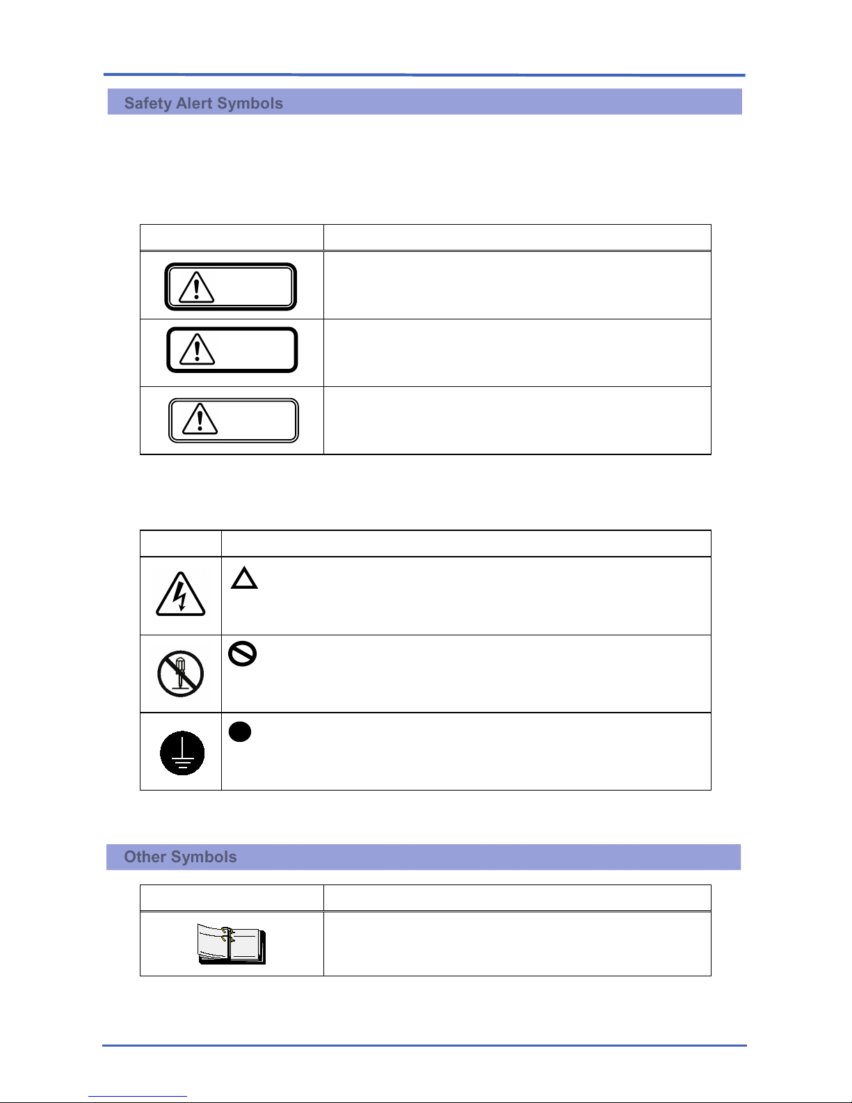
Safety Alert Symbols
Safety labeling is defined below.
Sections of the manual labeled with these symbols and signal words give warnings for equipment safety.
Consequences of neglecting to follow the warnings are classified as follows. Please read this information
carefully.
Symbol Meaning
Indicates a hazardous situation wh
ich, if not avoided, may
result in serious personal injury or property damage.
Indicates a potentially hazardous situation which, if not avoided,
may result in minor or moderate injury or property damage.
Indicates recommended guidelines that use
rs are urged to
follow to avoid equipment damage or wear, and to support
efficient usage.
To identify the nature of the potential damage or injury, the signal words described above are presented
with the following graphic symbols.
Symbol Meaning
Operators are warned and cautioned regarding the risk inside the warning
sign. Specific risks (in the example at left, electric shock) are depicted in warning
signs.
Prohibited actions are indicated
in a prohibition sign. Specific prohibited
actions (in the example at left, disassembly) are depicted in prohibition signs.
Operators are urged to follow the instructions associated with the symbol.
Specific instructions (in the example at left, equipment grounding) are depicted in
advisory signs.
Other Symbols
Symbol Meaning
TE
NO
Explanatory notes give supplemental, related information for
reference.
Caution
Warning
Notice

Contents
| 7
RN1-4696.01
Chapter 1
External Output Overview .......................................................................................................... 9
1-1 Types of External Output ................................................................................................................. 10
1-2 External Output Connection Procedure ........................................................................................... 11
1-2-1 RS-232C Output ........................................................................................................................ 11
1-2-2 USB output ............................................................................................................................... 12
1-2-3 LAN output ................................................................................................................................ 13
1-3 External output settings ................................................................................................................... 14
1-3-1 Output during measurement .................................................................................................... 14
1-3-2 Exporting Measurement Results .............................................................................................. 18
Chapter 2 RS-232C Output ....................................................................................................................... 21
2-1 RS-232C Output Format Settings ................................................................................................... 22
2-2 RS-232C Output Format Types ....................................................................................................... 23
2-3 Connector ......................................................................................................................................... 24
2-4 RS-232C output data configuration ................................................................................................. 25
2-4-1 RS1 Format .............................................................................................................................. 25
2-4-2 RS2 Format .............................................................................................................................. 32
2-4-3 RS3 Format .............................................................................................................................. 34
2-5 RS-232C Protocol ............................................................................................................................ 35
Chapter 3 Output via an Ethernet connection or USB flash drive ........................................................... 37
3-1 Output Specifications ....................................................................................................................... 38
3-2 LAN output settings ......................................................................................................................... 39
3-3 Output Format Types ....................................................................................................................... 42
3-4 Folder Naming.................................................................................................................................. 43
3-5 File Naming ...................................................................................................................................... 44
3-5-1 Type 1 ....................................................................................................................................... 44
3-5-2 Type 2 ....................................................................................................................................... 46
3-5-3 Type 3 ....................................................................................................................................... 47
3-6 Output Data Structure ...................................................................................................................... 48
3-6-1 Type 1 ....................................................................................................................................... 48
3-6-2 Type 2 ....................................................................................................................................... 49
3-6-3 Type 3 ....................................................................................................................................... 49
3-6-4 Measurement Data Headings of the data output in LAN or USB output. ............................... 50
Chapter 4 External Output Format Details ............................................................................................... 55
4-1 Type 1 Format .................................................................................................................................. 56
4-2 Type 2 Format .................................................................................................................................. 99
4-3 Type 3 Format ................................................................................................................................ 107

Contents
8 |
RN1-4696.01

Chapter 1 External Output Overview
Chapter 1 External Output Overview | 9
RN1-4696.01
Chapter 1 External Output Overview
This chapter describes external output from the equipment.

Chapter 1 External Output Overview
10 | 1-1 Types of External Output
RN1-4696.01
1-1 Types of External Output
You can connect LSC-8000 to other devices to use system's output functions to export measurement data
to the devices.
Three types of external output are supported: via RS-232C, USB, and Ethernet.
(1) RS-232C Output
We also provide the data acquisition software (Code: RPR-LSC-584B) for acquiring, viewing and
analyzing the measurement data. The measurement data can be exported to a computer running data
acquisition software by connecting LSC-8000 to the computer via an RS-232C cable.
The data files exported can then be viewed and analyzed using the data acquisition software.
(2) USB Output
Measurement data can be exported in CSV file format to USB flash drives connected to the system.
The data files exported can then be viewed and analyzed using commercially available spreadsheet
software.
(3) LAN Output
Measurement data can also be exported in CSV file format to the shared folders of computers
connected to the system via an Ethernet cable.
The data files exported can then be viewed and analyzed using commercially available spreadsheet
software.
Chapter 1 External Output Overview
1-2 External Output Connection Procedure | 11
RN1-4696.01
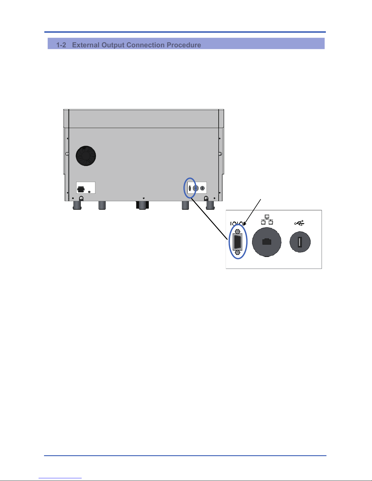
1-2 External Output Connection Procedure
1-2-1 RS-232C Output
Measurement data can be exported to a computer running data acquisition software by connecting the
computer to LSC-8000 via an RS-232C cable.
Rear view
Connect an RS-232C cable.
Chapter 1 External Output Overview
12 | 1-2 External Output Connection Procedure
RN1-4696.01
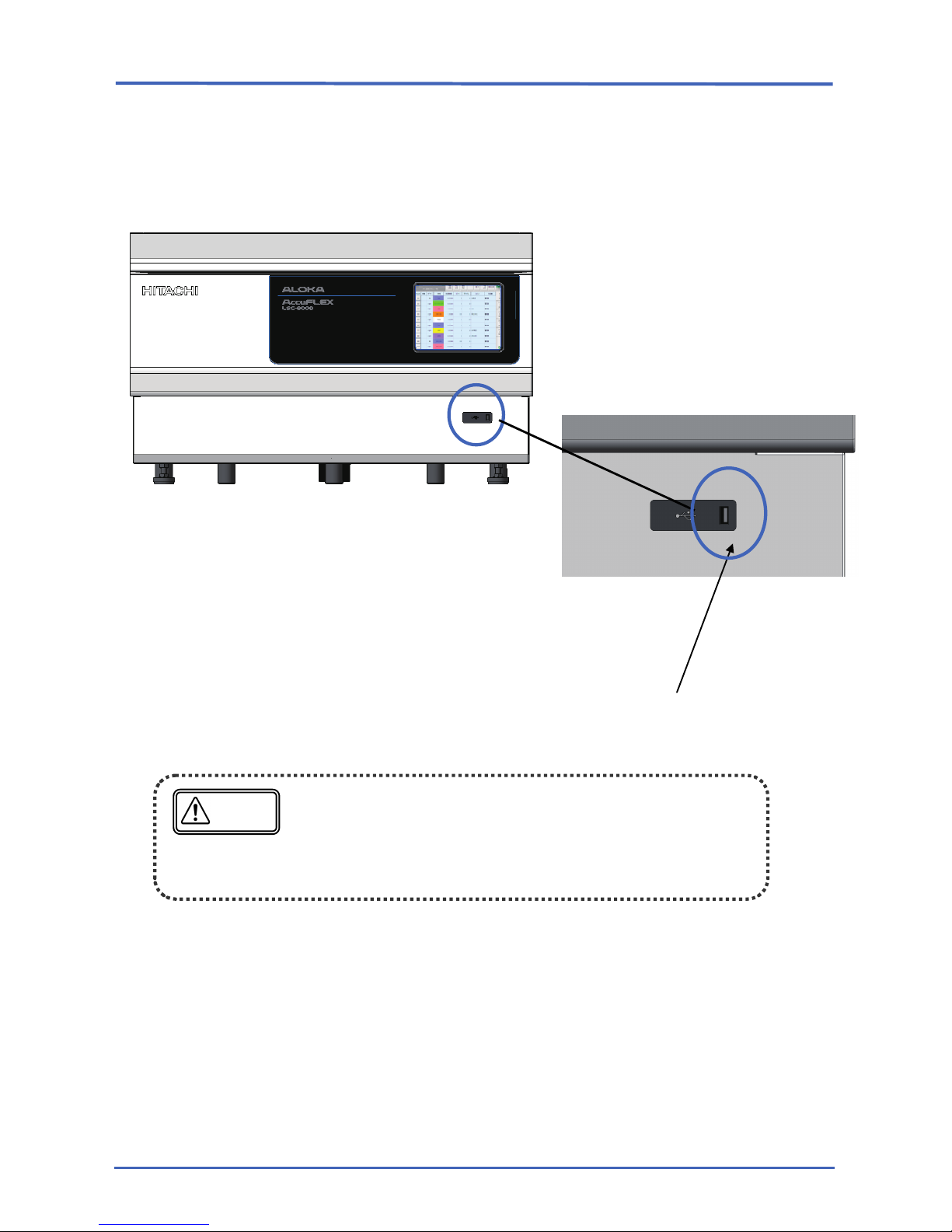
1-2-2 USB output
Measurement data can be exported to USB flash drives connected to LSC-8000.
No additional software is needed.
Do not connect keyboards, mouse devices, or other peripherals to the
USB port.
To avoid infecting LSC-8000 with computer viruses, do not use
USB flash drives that have been connected to computers which
were not protected from viruses.
Notice
Front view
Connect a USB flash drive.
Chapter 1 External Output Overview
1-2 External Output Connection Procedure | 13
RN1-4696.01
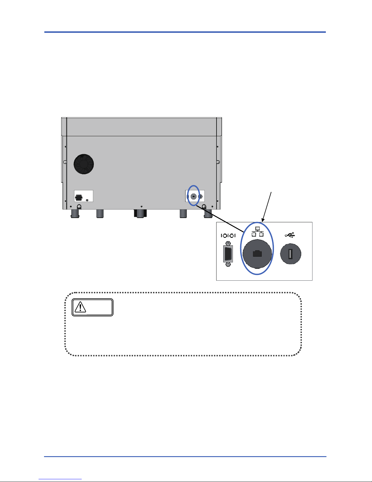
1-2-3 LAN output
Measurement data can be exported to the shared folders of computers connected to LSC-8000 via an
Ethernet cable. No additional software is needed.
To protect the equipment from the threat of computer viruses, limit connections to the local network. For
details of Ethernet connection, see Section 3-2.
To avoid infecting LSC-8000 with computer viruses, connect the
system to computers in the following kinds of networks.
Computers running antivirus software that are not connected
to external networks
Computers protected by firewalls to prevent unauthorized
access from external networks
Notice
Connect an Ethernet cable.
Rear view
Chapter 1 External Output Overview
14 | 1-3 External output settings
RN1-4696.01
1-3 External output settings
Data can be exported in two ways: output during measurement or output of measurement results (after
measurement).
If a password has been set in the system conditions, exporting measurement results must be done by
users with administrator or registered rights.
1-3-1 Output during measurement
(1) Output during automatic measurement
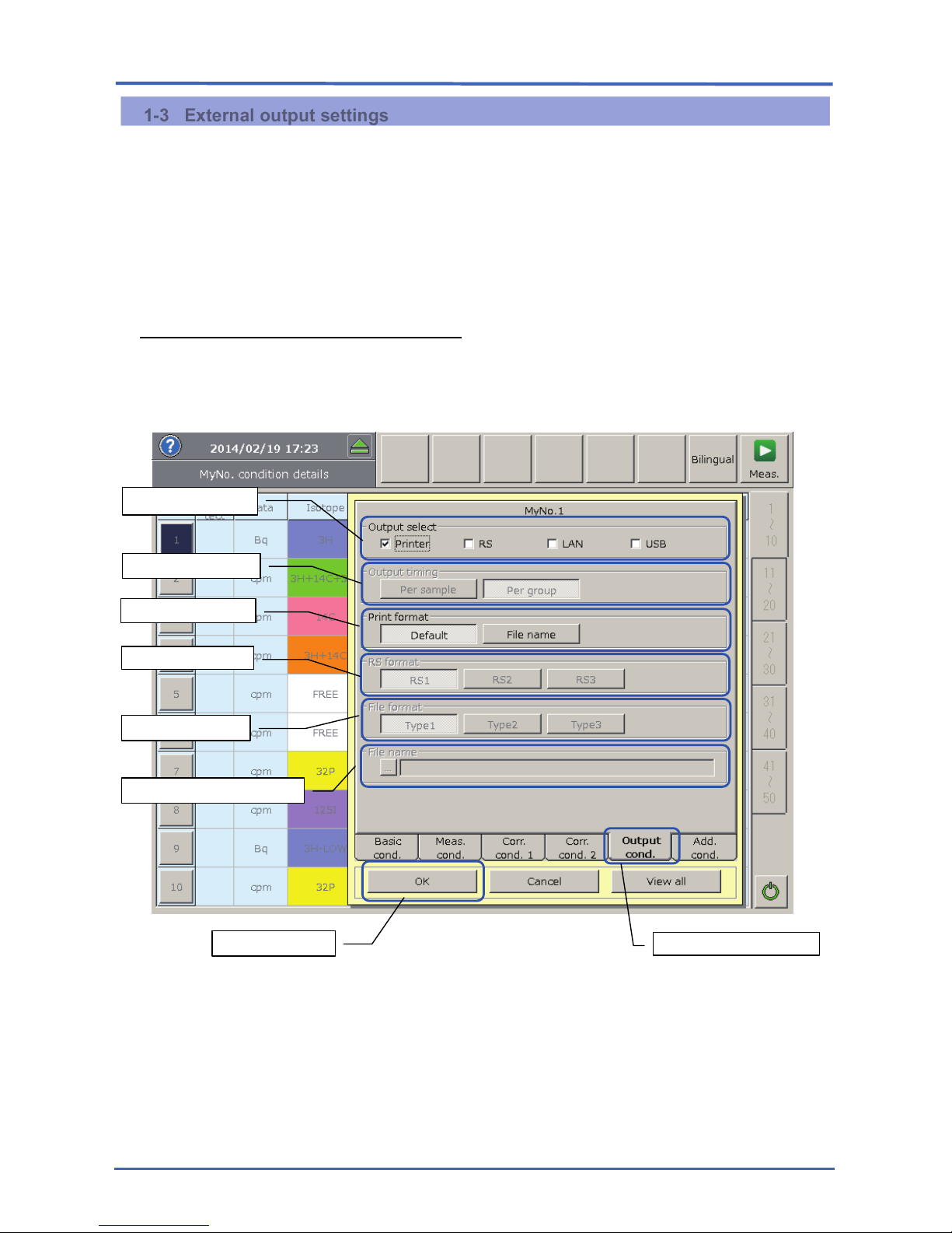
External output during measurement can be configured on the Output Conditions tab of the MyNo.
Detailed Settings screen (For details, refer to the Operation Manual, Section 4-3).
① Output Conditions
Output during measurement can be configured on the Output Conditions tab of the MyNo.
Condition Details screen. This tab is available in Custom, optional LUMI or α/β mode.
The settings cannot be configured in other modes.
② Output select
Select the destination for measurement data.
Measurement data is sent to selected output destinations.
①
Output Conditions
② Output select
③ Output Timing
④ Print format
⑤ RS format
⑥ File Format
⑦ File Name Input Area
⑧ OK button
Chapter 1 External Output Overview
1-3 External output settings | 15
RN1-4696.01
③ Output Timing
This option is available when you have selected either LAN or USB in ②.
As for the timing for exporting data to the selected output destinations, you can send the data for
each sample or for each group.
④ Print Format
Select the print format.
To specify a file name, select File name and choose the name in the selection box displayed. (For
print format setting details, refer to the Operation Manual, Section 6-8.)
⑤ RS Format
This option is available when you have selected RS in ②.
Select the file format when exporting via RS-232C.
*RS3 format follows Print Format settings in ④.
⑥ Output format
This option is available when you have selected either LAN or USB in ②.
Select the file format when exporting via Ethernet or USB.
*Type3 format follows Print Format settings in ④.
⑦ File name input area
This option is available when you have selected either LAN or USB in ②.
Specify the file name when exporting via Ethernet or USB.
Note that the number of characters available for the file name is determined by the file format
selected in ⑥.
Type 1: Up to 6 single-byte characters.
Spectrum file names are three characters or less. (If you specify four
characters or more, the extra characters will be truncated.)
Types 2 or 3: Up to 20 single-byte or 10 double-byte characters. (Alphanumeric characters
and French or Chinese supported.)
* The following characters are illegal characters in Windows. Do not use these characters in file
names. ( ¥ , / , : , * , ? , " , < , > , | )
⑧ OK Button
When you are finished programming output conditions, press the OK button.
The data output during measurement will consist of both
cpm・dpm
data and spectrum data. It is not possible to select
just one type.
Pressing the STOP b
utton will cancel output for the samples
being measured, and this data (which is not fini
shed being
measured) will not be exported.
TE
NO
Chapter 1 External Output Overview
16 | 1-3 External output settings
RN1-4696.01
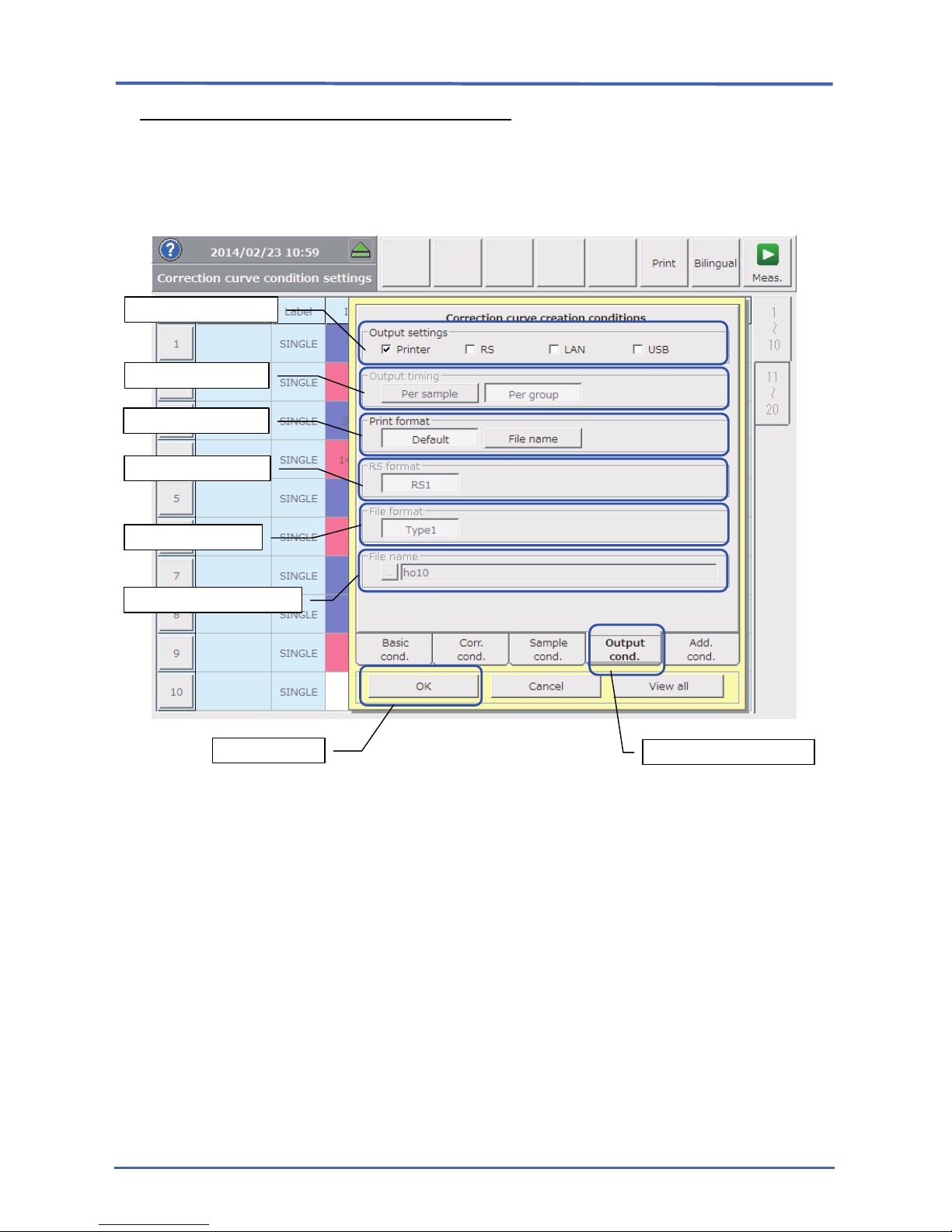
(2) Output during correction curve measurement
External output during measurement when preparing correction curves can be configured on the
Output Conditions tab of the Correction Curve Settings screen (For details, refer to the Operation
Manual, Section 5-4-1).
① Output Conditions
Output during measurement can be configured on the Output Conditions tab of the Correction
Curve Condition Settings screen.
② Output settings
Select the destination for measurement data.
Measurement data is sent to selected output destinations.
② Output Timing
This option is available when you have selected either LAN or USB in ②.
As for the timing for exporting data to the selected output destinations, you can send the data for
each sample or for each group.
④ Print Format
Select the print format.
To specify a file name, select File name and choose the name in the selection box displayed. (For
print format setting details, refer to Operation Manual, Section 6-8.)
① Output Conditions
② Output settings
③ Output Timing
④ Print format
⑤ RS format
⑥ File Format
⑦ File Name Input Area
⑧ OK button
Chapter 1 External Output Overview
1-3 External output settings | 17
RN1-4696.01
⑤ RS Format
This option is available when you have selected RS in ②.
Select the file format when exporting via RS-232C. Only RS1 is available during measurement to
prepare correction curves.
⑥ Output Format
This option is available when you have selected either LAN or USB in ②.
Select the file format when exporting via Ethernet or USB. Only Type 1 is available during
measurement to prepare correction curves.
⑦ File Name Input Area
This option is available when you have selected either LAN or USB in ②.
Specify the file name when exporting via Ethernet or USB.
Note that the number of characters available for the file name is determined by the file format
selected in ⑥.
Type 1: Up to 6 single-byte characters.
Spectrum file names are three characters or less. (If you specify four
characters or more, the extra characters will be truncated.)
* The following characters are illegal characters in Windows. Do not use these characters in file
names. ( ¥ , / , : , * , ? , " , < , > , | )
⑧ OK button
When you are finished programming output conditions, press the OK button.
To specify other conditions, refer to the Operation Manual, Section 5-4, as you continue
programming.
Pressing the STOP button will cancel output for the samples
being measured
, and this data (
which is not finished being
measured) will not be exported.
TE
NO
Chapter 1 External Output Overview
18 | 1-3 External output settings
RN1-4696.01
1-3-2 Exporting Measurement Results
All sample measurement data is saved on the equipment's internal hard disk. The stored measurement
data can be exported to a PC via an Ethernet connection or to a USB flash drive.
Data files can be exported using the File management function on the Control/Calibration menu.
For details of how to use the file management function, refer to the Operation Manual, Section 8-9.
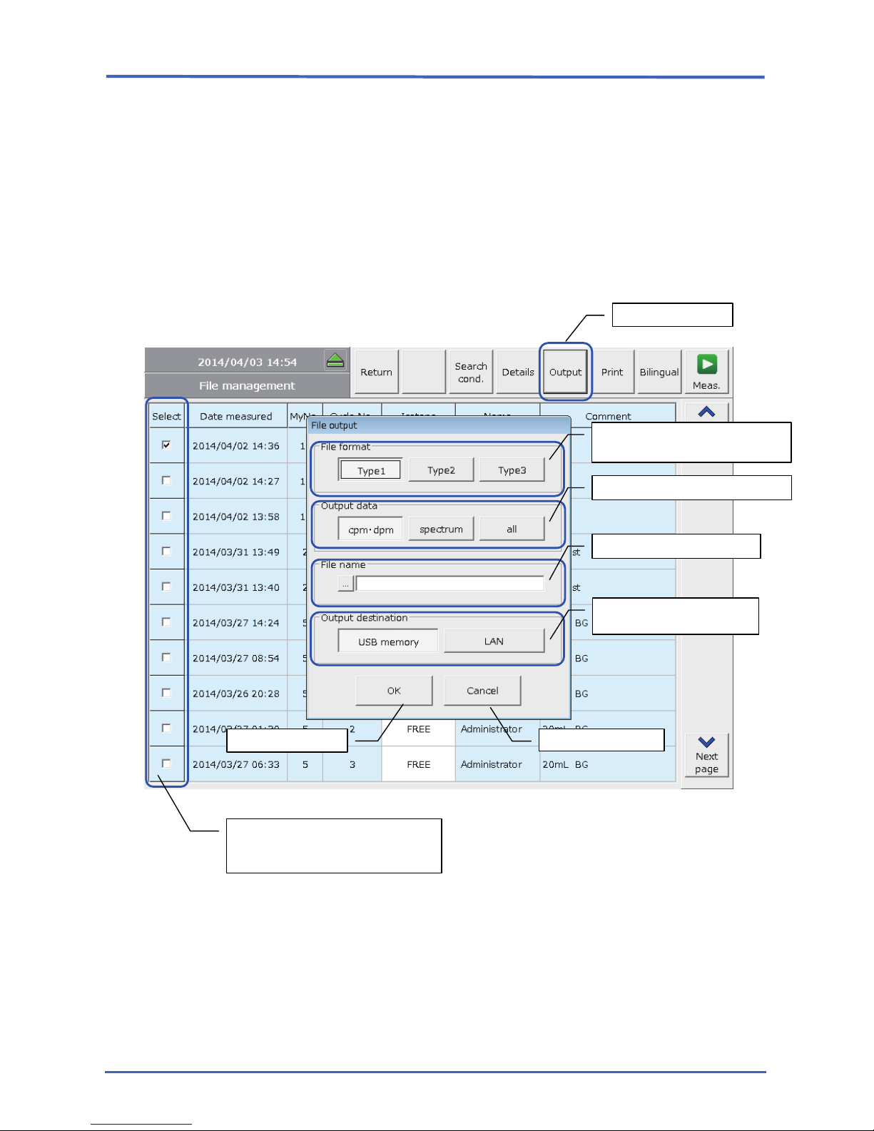
Pressing the Output button on the File management screen will display a File Output screen.
1. Output button
This button becomes available once you have selected at least one item in the Select column.
Although multiple items can be selected, this increases the time required for output of data files.
We recommend selecting no more than five items, because other operations are not possible
during data file output.
Select desired items in the Select
column and press the Output
button.
1. Output button
2. Output format
selection area
4. File name input area
5. Output destination
selection area
6. OK button
7. Cancel button
3. Output data selection area

Chapter 1 External Output Overview
1-3 External output settings | 19
RN1-4696.01
2. Output format
Select the file format when exporting via USB or Ethernet.
3. Output data
Select the type of data file to export via Ethernet or USB.
cpm・dpm: Export only cpm・dpm data files, without spectrum data files.
With this option, a smaller amount of data is exported than when exporting all
data, which enables many data files to be exported in a short period.
Spectrum: Export only spectrum data files, without cpm・dpm data files.
Because spectrum files are larger than cpm・dpm data files, exporting takes
some time.
All: Export both cpm・dpm data files and spectrum data files.
As with the Spectrum option described above, exporting will take some time.
4. File name
Specify the file name when exporting via Ethernet or USB.
Note that the number of characters available for the file name is determined by the output type
selected in 2.
Type 1: Up to 6 single-byte characters.
Spectrum file names are three characters or less. (If you specify four
characters or more, the extra characters will be truncated.)
Types 2 or 3: Up to 20 single-byte or 10 double-byte characters. (Alphanumeric characters
and French or Chinese supported.)
* The following characters are illegal characters in Windows. Do not use these characters in
file names. ( ¥ , / , : , * , ? , " , < , > , | )
5. Output destination
Select the destination for the data files.
Select either USB or LAN. (Both destinations cannot be selected at the same time.)
6. OK button
Exports data files according to the information specified in steps 2 to 5.
7. Cancel button
Discards information specified in steps 2 to 5 and cancels output of data files.
Only Type 1 output is available for results from preparing correction
curves, validation, normalization, and automatic calibration.
In this case, Types 2 and 3 cannot be specified.
If the measurement data with Print format unspecified is exported in
the Type3 format, the data is exported in the default Print format.
TE
NO
If the measurement data of validation, normalization or auto
calibration is exported, Output data cannot be specified.
TE
NO

Chapter 1 External Output Overview
20 | 1-3 External output settings
RN1-4696.01

Chapter 2 RS-232C Output
Chapter 2 RS-232C Output | 21
RN1-4696.01
Chapter 2 RS-232C Output
This chapter describes RS-232C output.
Chapter 2 RS-232C Output
22 | 2-1 RS-232C Output Format Settings
RN1-4696.01
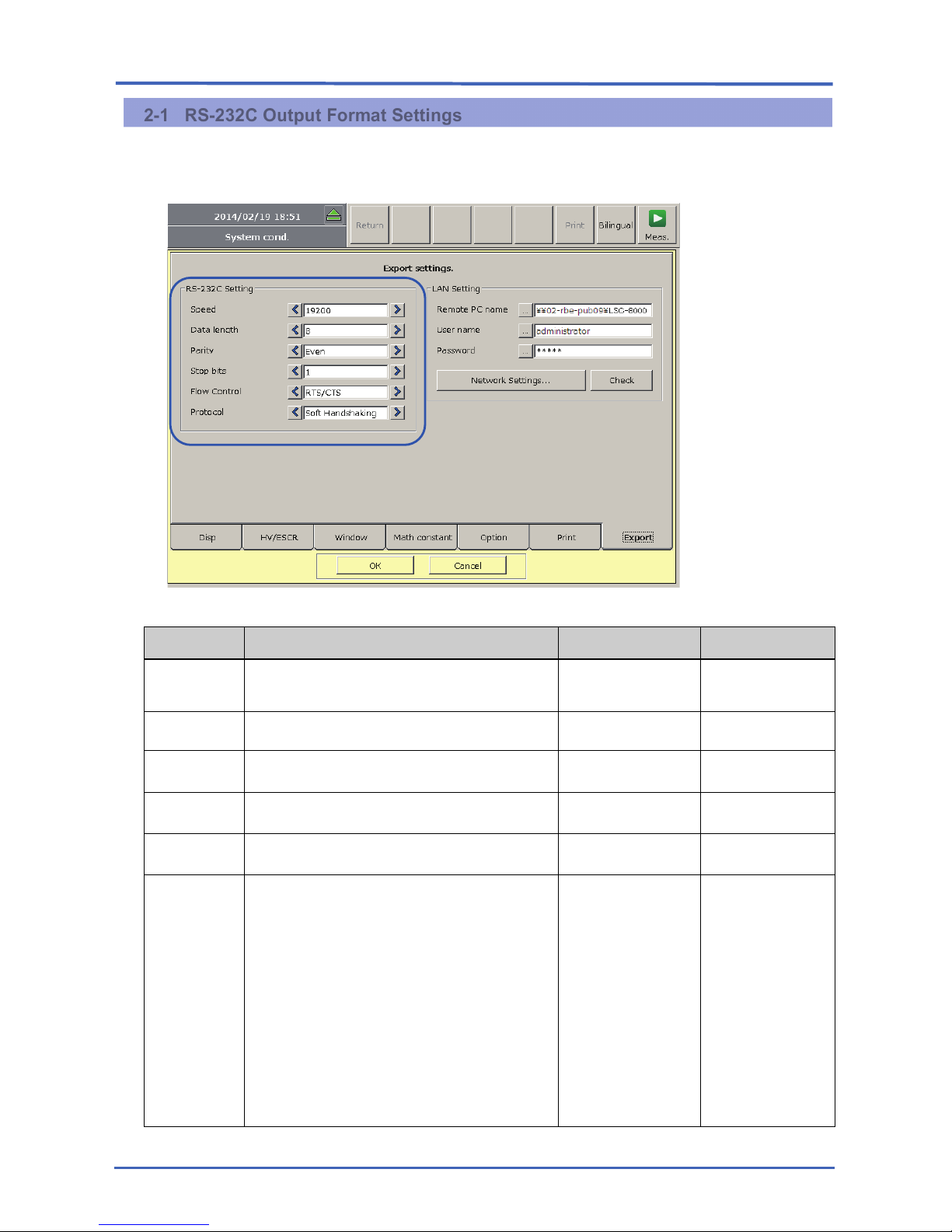
2-1 RS-232C Output Format Settings
The RS-232C output method can be configured from Export in the System conditions on the
Control/Calibration menu.
RS-232C Setting
Item Function Input range Default setting
Speed
Specify the data transfer speed (baud rate). (Unit:
bps)
4800/9600/19200 19200
Data length Specify the data length. (Unit: bits) 7/8
8
Parity Specify the type of vertical redundancy checking. Even/Odd/None Even
Stop bits Specify the stop bit length. (Unit: bits) 1/1.5/2 1
Flow Control Specify the data flow control method. RTS/CTS / None
None
Protocol
Specify the communication protocol to use for
measurement data.
Match the settings used by standard Hitachi Aloka
Medical data acquisition software.
Soft Handshaking
data during the transmission
and reception process with the data acquisition
software.
No-protocol
Output measurement data without a transmission
and reception process with the data acquisition
software.
Soft handshaking
/No-protocol
Soft handshaking
Chapter 2 RS-232C Output
2-2 RS-232C Output Format Types | 23
RN1-4696.01
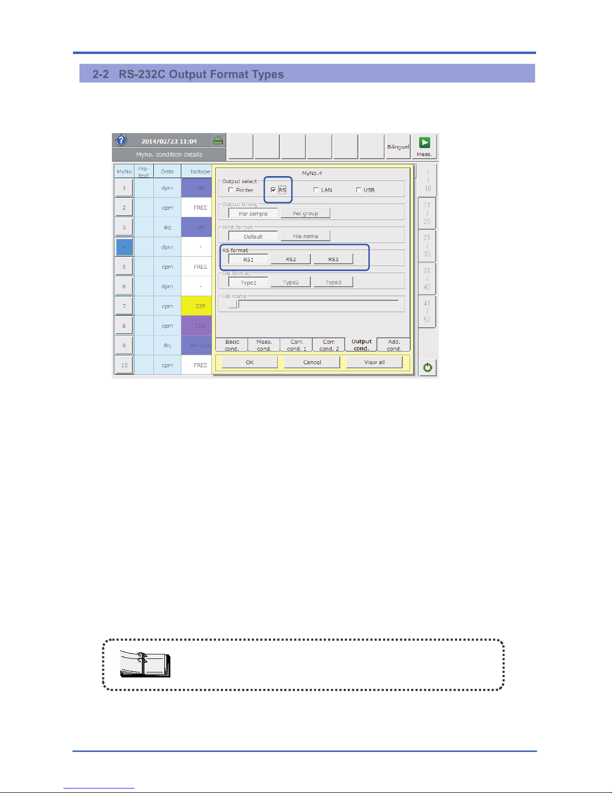
2-2 RS-232C Output Format Types
The RS format type can be selected by selecting RS in the output conditions on the screen for exporting
MyNo. conditions.
There are three different RS-232C output formats, as shown below.
RS1
Same output format as used by existing Hitachi Aloka Medical equipment (LSC-7200, LSC-7400, and
LSC-LB7), for users of these systems.
RS2
For exporting all measurement data and measurement conditions.
RS3
For selecting desired parameters of measurement data in RS2 items to export.
The order of output can also be freely selected.
Selection and order of parameters follows the MyNo. conditions print format settings.
When you plan to export data via RS-232C, enter any measurement
condition notes using single-byte characters. Be aware that double-byte
characters may cause character corruption.
TE
NO
Chapter 2 RS-232C Output
24 | 2-3 Connector
RN1-4696.01
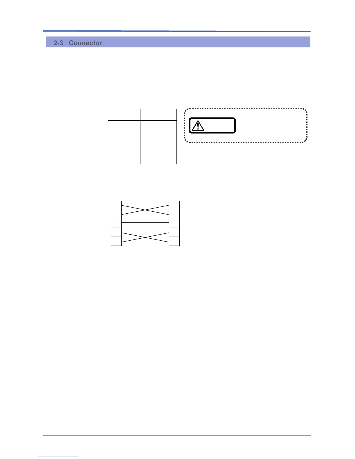
2-3 Connector
Use an RS-232C cable (D-Sub 9-pin female - D-Sub 9-pin female, reversed type).
Type: D-Sub 9-pin (male)
Signals:
Cable: Reverse cable
Connection example:
Do not use pins other
than those indicated
on the left.
Equipment side
Computer side
(9-pin female)
(9-pin female)
2
3
5
7
8
2
3
5
7
8
Pin No.
Signal
2
3
5
7
8
RXD
TXD
SG
RTS
CTS
Caution
Chapter 2 RS-232C Output
2-4 RS-232C output data configuration | 25
RN1-4696.01
2-4 RS-232C output data configuration
The data output in RS-232C output will consist of (1) cpm・dpm data and (2) spectrum data. Note
thatmeasurement data on the Control/Calibration menu, such as validation measurement data or
automatic calibration measurement data is not output.
The configuration of the data output will differ depending on the RS format selected.
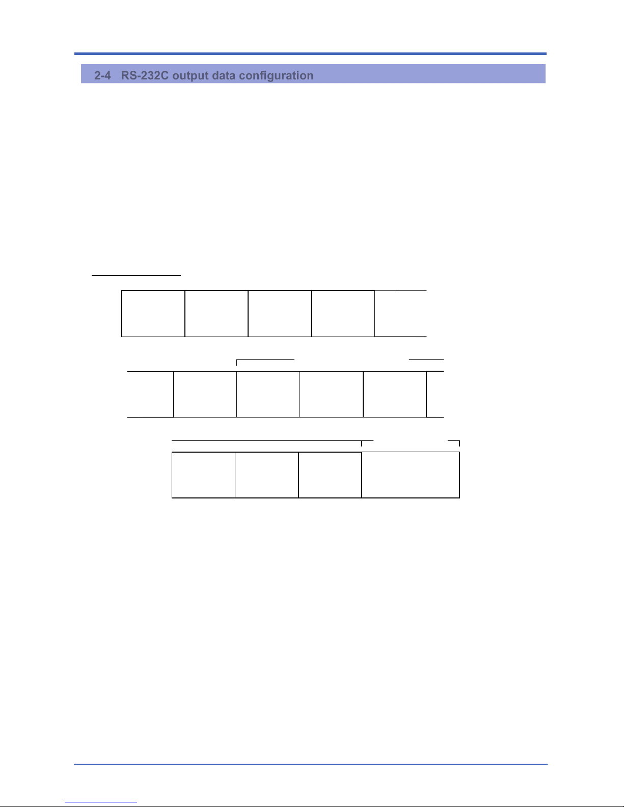
2-4-1 RS1 Format
Details of data such as group conditions and measurement data headings follow the Type 1 format.
For details, see 4-1.
(1) cpm・dpm data
Group
Conditions
Measurement
Data
Heading
cpm・dpm
Data
(1)
cpm・dpm
Data
(2)
........
Group
Conditions
Measurement
Data
Heading
cpm・dpm Data
(1)
........
cpm・dpm Data
(n)
Next
MyNo. Post Data
Stop Data
cpm・dpm Data
(n)
cpm・dpm Data
(2)
Output When
Stopped
Chapter 2 RS-232C Output
26 | 2-4 RS-232C output data configuration
RN1-4696.01
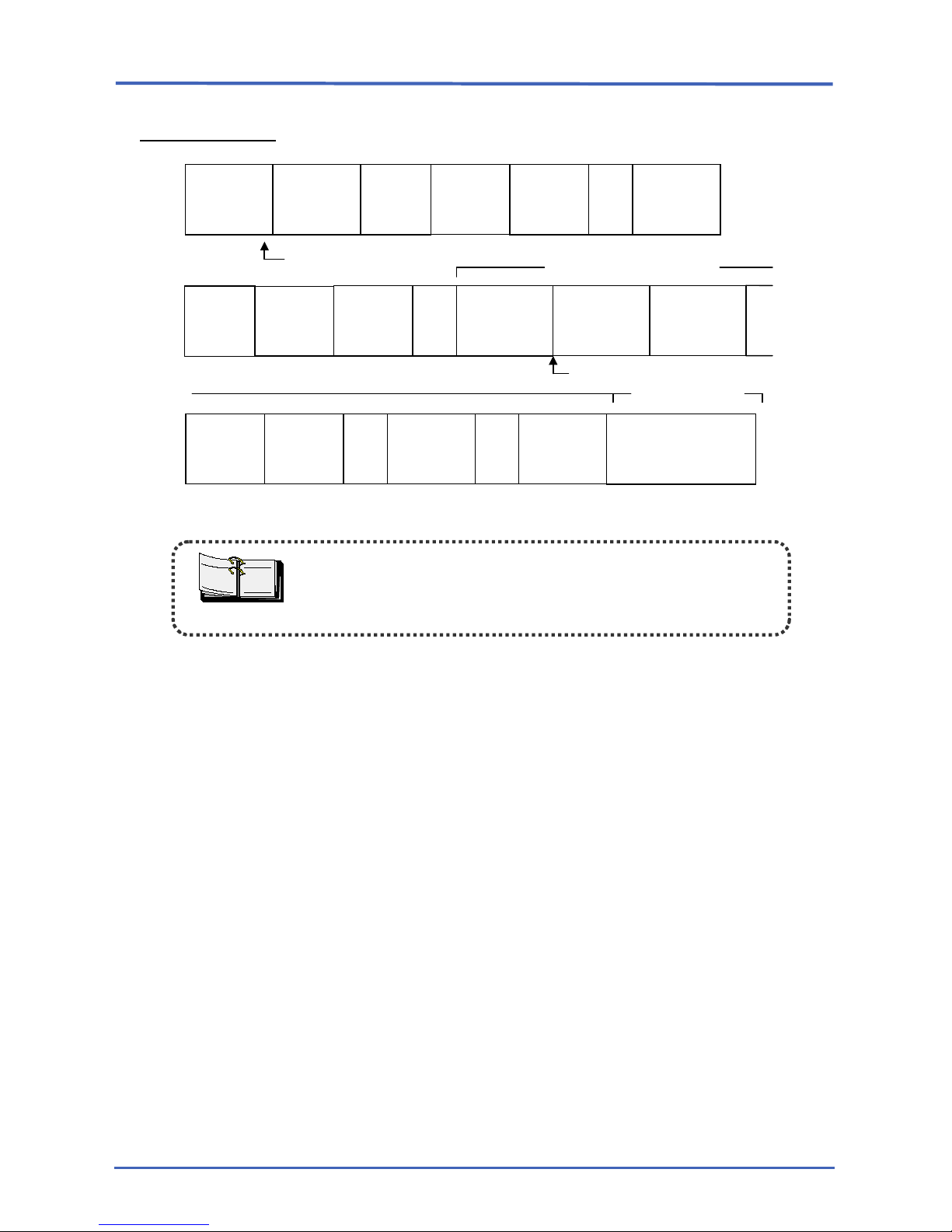
(2) Spectrum data
Spectrum Request Command
Group
Conditions
Measurement
Data
Heading
cpm・dpm
Data (1)
Spectrum
Data
Ch. 0–9
Spectrum
Data
Ch. 10–19
Spectrum
Data
Ch.
3990–3999
.....
Output When
Stopped
Stop Data
Spectrum
Data
Ch. 0–9
Spectrum
Data
Ch. 10–19
Spectrum
Data
Ch.
3990–3999
.....
Spectrum
Data
Ch.
3990–3999
.....
Next
MyNo. Post Data
cpm・dpm
Data (2)
Group
Conditions
Measurement
Data
Heading
cpm・dpm
Data
(1)
Spectrum
Data
Ch. 0–9
Spectrum
Data
Ch. 10–19
.....
Spectrum Request
T
E
NO
Data begins with an STX code and is terminated with an ETX code.
Digit numbers are indicated in parenthesis.
Even if half-
life correction is selected, the cpm, dpm, and Bq values
exported are the values before half-life correction.

Chapter 2 RS-232C Output
2-4 RS-232C output data configuration | 27
RN1-4696.01
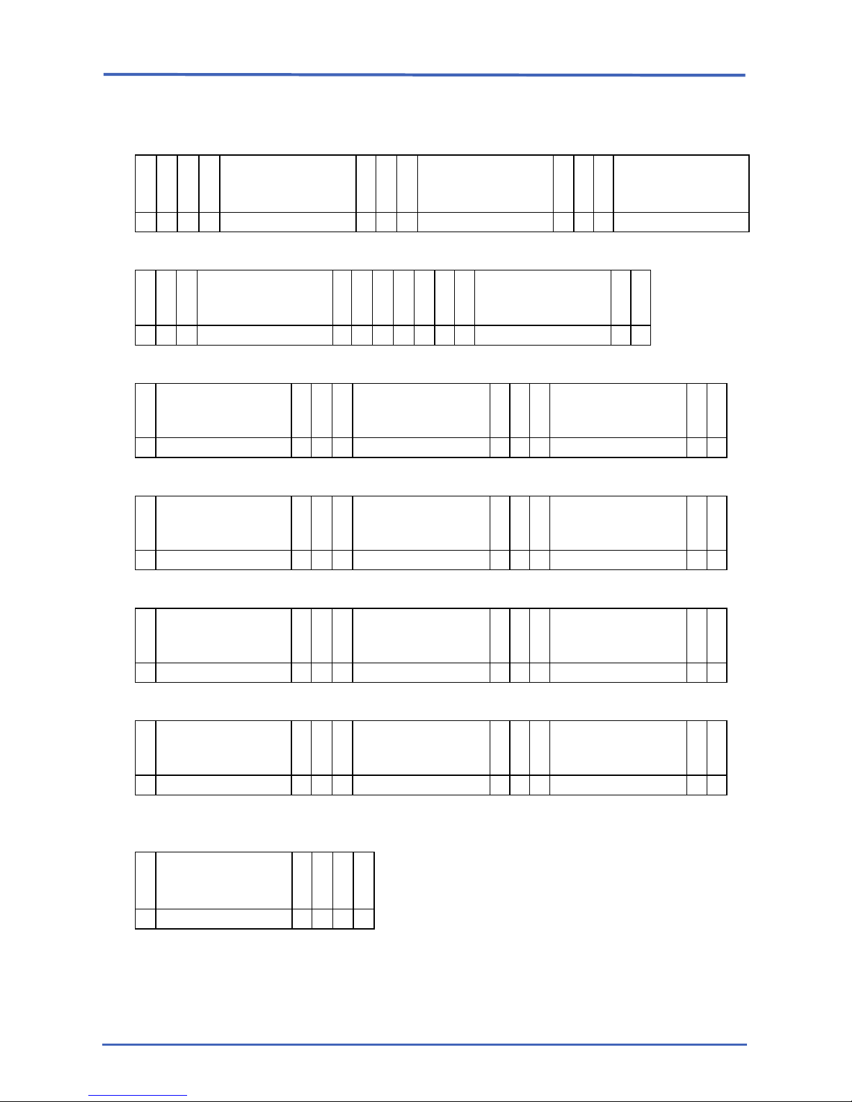
2-4-1-1 Number of data characters for RS1 output format
Group Conditions
1 4 91
S
T
X
G ,
Type 1: Group Conditions
E
T
X
× × × ×
For details of "Type 1: Group Conditions" data, see 4-1.
Chapter 2 RS-232C Output
28 | 2-4 RS-232C output data configuration
RN1-4696.01
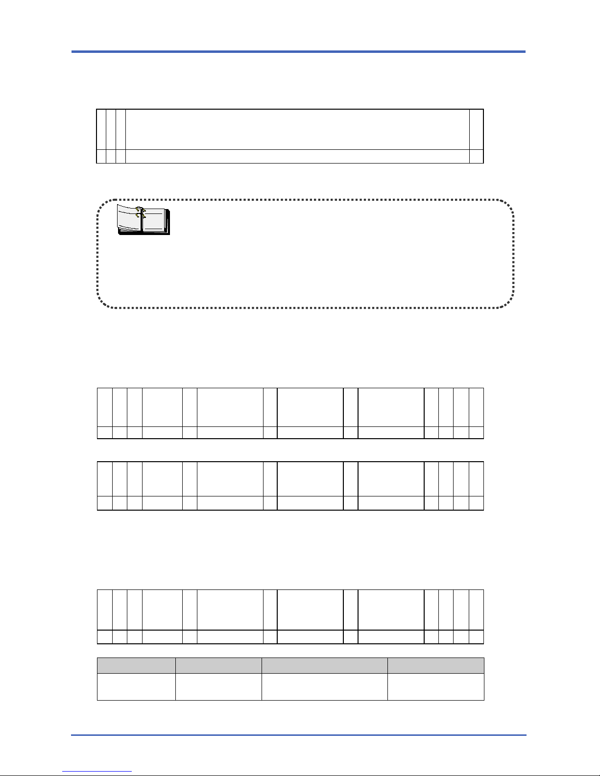
Measurement Data Headings (characters in these structures are exported just as they are)
1 5 17 29
S
T X T ,
”
MyNo.
(9)
” , ”
SN
(9)
” , ”
RN
(9)
× × ×
×
× × ×
× × ×
41 53 57
”
,
”
ESCR or SCCR
(9)
”
,
”
”
,
”
TIME
(9)
”
,
× × ×
××××
× × ×
¡ × ×
×
××××
×
×
69 81 93
”
A-GROSS
(9)
”
,
”
A-CPM
(9)
”
,
”
A-DPM or A-Bq
(9)
”
,
×
ЧЧЧЧЧЧЧ
× × ×
ЧЧЧЧЧ
× × ×
ЧЧЧЧЧ
×
×
105 117 129
”
A-EFF
(9)
”
,
”
B-GROSS
(9)
”
,
”
B-CPM
(9)
”
,
×
ЧЧЧЧЧ
× × ×
ЧЧЧЧЧЧЧ
× × ×
ЧЧЧЧЧ
×
×
141 153 165
”
B-DPM or B-Bq
(9)
”
,
”
B-EFF
(9)
”
,
”
C-GROSS
(9)
”
,
×
ЧЧЧЧЧ
× × ×
ЧЧЧЧЧ
× × ×
ЧЧЧЧЧЧЧ
× ×
177 189 201
”
C-CPM
(9)
”
,
”
C-DPM or C-Bq
(9)
”
,
”
C-EFF
(9)
”
,
× ЧЧЧЧЧ × × × ЧЧЧЧЧ × × × ЧЧЧЧЧ × ×
213
22
5
”
SCCR
(9)
”
C R L
F
E
T
X
×
××××
× × ×
×
Chapter 2 RS-232C Output
2-4 RS-232C output data configuration | 29
RN1-4696.01
cpm・dpm Data
1 4 204
S
T
X
D ,
Type 1: CPM・DPM Data
E
T
X
× × × ×
For details of "Type 1: CPM・DPM Data" data, see 4-1.
Spectrum Data
1 4 8 71 80
S
T
X
S ,
Block
No. 1 (3)
,
0 ch
Gross Data
(6)
, ..... ,
9 ch
Gross Data
(6)
,
C R L
F
E
T
X
× × ×
ЧЧЧ Ч ЧЧЧЧЧЧ Ч Ч ЧЧЧЧЧЧ
× × ×
× 1 4 8
71 80
S
T X S ,
Block
No. 2
(3)
,
10 ch
Gross Data
(6)
, ..... ,
19 ch
Gross Data
(6)
,
C R L
F
E
T
X
× × × ××× × ЧЧЧЧЧЧ × × ЧЧЧЧЧЧ × × × ×
.
.
.
.
.
1 4 8 71 80
S
T X S ,
Block
No. 400
(3)
,
3990 ch
Gross Data
(6)
, ..... ,
3999 ch
Gross Data
(6)
,
C R L
F
E
T
X
× × × ××× × ЧЧЧЧЧЧ × × ЧЧЧЧЧЧ × × × ×
Group Item Description Range
Spectrum Data Channels 0–3999
Total count for each channel
(0–3999)
0–9999999
T
E
NO
cpm
・dpm Data
1)
Data is exported as 204 digits in full.
2)
Portions without data are indicated by space.
Example:
In single-label measurement, B- and C-
channel data are
indicated by spaces.
In DATA: CPM, DPM or Bq is indicated by spaces.
3)
CPM is the net cpm value.
4)
Even if half-life correction is selected, the CPM, DPM
, and Bq values
exported are the values before half-life correction.
Chapter 2 RS-232C Output
30 | 2-4 RS-232C output data configuration
RN1-4696.01
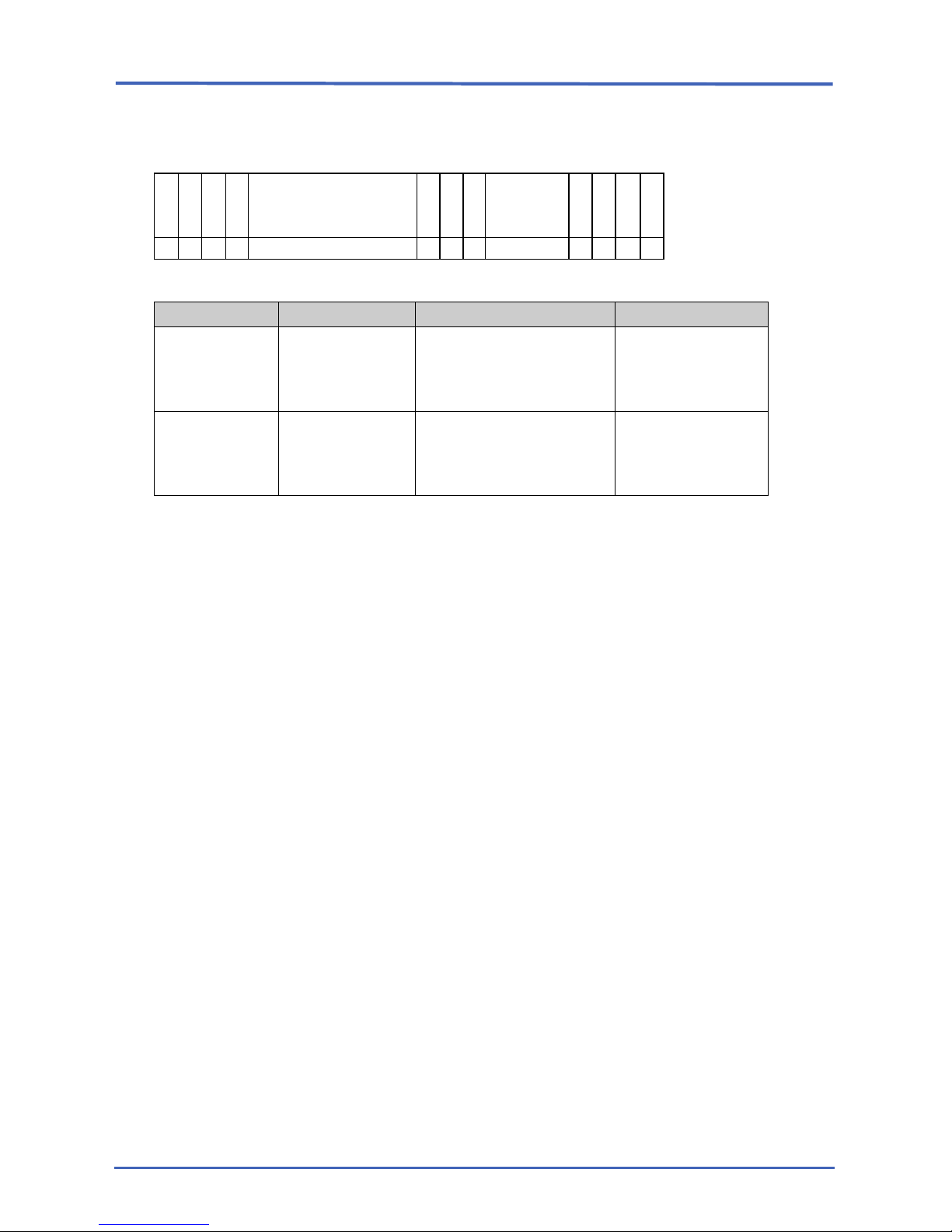
Stop Data
1 5 18 26
S
T X E ,
”
Year/Month/Day
(10)
”
,
”
Hour
(5)
”
C R L
F
E
T
X
× × × × ××××/××/×× × × × XX:XX × × × ×
Group Item Description Range
Stop Data Year/Month/Day
Date that measurement
was completed
(expressed in standard,
non-Japanese format)
YYYY/MM/DD
(2014/01/31)
Time
Time that measurement
was completed
(expressed in 24-hour
format)
hh:mm
(17:35)
 Loading...