

Page 1

Hitachi
VisionBase 8880R
Server
Product Guide
Page 2

Issue Date:
November 1998
Part Number:
Copyright:
© 1998 Hitachi Ltd. and Hitachi PC Corporation (USA). All rights reserved.
Hitachi is a registered tra demark of Hitachi Ltd. Mobilized Computing and Hitachi VisionBase are trademarks of
Hitachi PC Corporation (USA) and may be registered in some jurisdictions. All other brands and products and
service names mentioned are trademarks or registered service marks of their respective owners.
Trademarks
Microsoft, MS-DOS, Windows, and the Windows Logo are registered trademarks of Microsoft Corporation.
Intel is a registered trademark of Intel Corporation.
Pentium II is a registered trade mark of Int el Corporation.
IBM and PS/2 are trademarks of International Business Machines Corporation.
All other brands and product names are trademarks or registered trademarks of their respective holders.
Disclaimer
Hitachi PC Corporation has taken eve ry precaut ion to provide comple te and accu rate inf ormatio n in thi s document.
However, due to conti nuous efforts being made to improve and up date the product(s ), Hit achi s hall not be liable for
any technical or edit orial e rrors o r omis sions containe d in this doc ument, or for a ny damage, direct or indirect, from
discrepancies between the document and the product(s) it describes.
202-85031-01-Rev A
Information in this manual is subj ect to change without notice and does not represent a commitment on the part of
Hitachi PC Corporation.
Hitachi PC strongly recommends that you keep separate, permanent, written records of all important data, and
perform periodic backups. Data may be lost or altered in virtually any electronic memory product under certain
circumstances. Therefore, Hitachi PC assumes no responsibility for data loss or data otherwise rendered unusable
whether as a result of improper use, repair s, defects, or any other causes.
Hitachi PC assumes no responsibil ity directly or indire ctly, for financial lo sses or claims from third persons re sulting
from the use of this produc t an d any of its functions, such as st ole n credit card numbers, the los s of or a lteration of
stored dat a, etc.
Disclaimer
Intel Corporation (Int el ) makes no warranty of any kind with regard to this material, including, but not limited to,
the implied warranties of merchantability and fitness for a particul ar purpose. Intel assumes no responsibility for
any errors that may appear in this document. Intel makes no commitment to upda te nor to keep current the
information contained in this document. No part of this document may be copied or reproduced in any form or by
any means without prior written consent of Intel.
An Intel product, when used in accordance with its associated documentation, is “Year 2000 Capable” when, upon
installation, it acc urately s tores, di splays, proc esses, pr ovid es, and/or receive s date da ta f rom, into, and be tween the
twentieth and twenty-first centuries, including leap year calculations, provided that all other technology used in
combination with said product properly exchanges date data with it.
Third-party brands and trademarks are the property of their respective owners.
Copyright © 1998, Intel Corporation.
Page 3

Contents
Contents
1: Hardware
System Overview . . . . . . . . . . . . . . . . . . . . . . . . . . . . . . . . . . . . . . . . . . . . . . . . . . . . . . . . . . . . . . . . . . . . . . . . . . . . . . . . . 1
Powering-On the System . . . . . . . . . . . . . . . . . . . . . . . . . . . . . . . . . . . . . . . . . . . . . . . . . . . . . . . . . . . . . . . . . . . . . . . . . . . 4
Front Panel . . . . . . . . . . . . . . . . . . . . . . . . . . . . . . . . . . . . . . . . . . . . . . . . . . . . . . . . . . . . . . . . . . . . . . . . . . . . . . . . . . . . . . 5
Back Panel . . . . . . . . . . . . . . . . . . . . . . . . . . . . . . . . . . . . . . . . . . . . . . . . . . . . . . . . . . . . . . . . . . . . . . . . . . . . . . . . . . . . . . 7
Removing the Server Panels and Accessing Its Components . . . . . . . . . . . . . . . . . . . . . . . . . . . . . . . . . . . . . . . . . . . . . . . 8
Safety Guidelines . . . . . . . . . . . . . . . . . . . . . . . . . . . . . . . . . . . . . . . . . . . . . . . . . . . . . . . . . . . . . . . . . . . . . . . . . . . . . . . . . 8
Warnings and Cautions. . . . . . . . . . . . . . . . . . . . . . . . . . . . . . . . . . . . . . . . . . . . . . . . . . . . . . . . . . . . . . . . . . . . . . . . . . . . . 8
Tools and Supplies You Need . . . . . . . . . . . . . . . . . . . . . . . . . . . . . . . . . . . . . . . . . . . . . . . . . . . . . . . . . . . . . . . . . . . . . . . 8
Accessing the PCI Slots . . . . . . . . . . . . . . . . . . . . . . . . . . . . . . . . . . . . . . . . . . . . . . . . . . . . . . . . . . . . . . . . . . . . . . . . . . . . 9
PCI/ISA Option Boards . . . . . . . . . . . . . . . . . . . . . . . . . . . . . . . . . . . . . . . . . . . . . . . . . . . . . . . . . . . . . . . . . . . . . . . . . . . 10
Hard Disk Drives . . . . . . . . . . . . . . . . . . . . . . . . . . . . . . . . . . . . . . . . . . . . . . . . . . . . . . . . . . . . . . . . . . . . . . . . . . . . . . . . 11
Optional Devices . . . . . . . . . . . . . . . . . . . . . . . . . . . . . . . . . . . . . . . . . . . . . . . . . . . . . . . . . . . . . . . . . . . . . . . . . . . . . . . . 13
CPU . . . . . . . . . . . . . . . . . . . . . . . . . . . . . . . . . . . . . . . . . . . . . . . . . . . . . . . . . . . . . . . . . . . . . . . . . . . . . . . . . . . . . . . . . . 14
Memory . . . . . . . . . . . . . . . . . . . . . . . . . . . . . . . . . . . . . . . . . . . . . . . . . . . . . . . . . . . . . . . . . . . . . . . . . . . . . . . . . . . . . . . 15
Jumper Settings . . . . . . . . . . . . . . . . . . . . . . . . . . . . . . . . . . . . . . . . . . . . . . . . . . . . . . . . . . . . . . . . . . . . . . . . . . . . . . . . . 17
2: System Environment Setting
Before Operations. . . . . . . . . . . . . . . . . . . . . . . . . . . . . . . . . . . . . . . . . . . . . . . . . . . . . . . . . . . . . . . . . . . . . . . . . . . . . . . . 19
Setup Menu. . . . . . . . . . . . . . . . . . . . . . . . . . . . . . . . . . . . . . . . . . . . . . . . . . . . . . . . . . . . . . . . . . . . . . . . . . . . . . . . . . . . . 22
ISA Configuration Utility (ICU) . . . . . . . . . . . . . . . . . . . . . . . . . . . . . . . . . . . . . . . . . . . . . . . . . . . . . . . . . . . . . . . . . . . . 36
. . . . . . . . . . . . . . . . . . . . . . . . . . . . . . . . . . . . . . . . . . . . . . . . . . . . . . . . . . . . . . . . . . . . . . . . . . . . . . . . . . . . . . . 1
System Specifications . . . . . . . . . . . . . . . . . . . . . . . . . . . . . . . . . . . . . . . . . . . . . . . . . . . . . . . . . . . . . . . . . . . . . . . . . . 1
SCSI SCA Hard Disk Drives . . . . . . . . . . . . . . . . . . . . . . . . . . . . . . . . . . . . . . . . . . . . . . . . . . . . . . . . . . . . . . . . . . . 11
Installing/Swapping a HDD . . . . . . . . . . . . . . . . . . . . . . . . . . . . . . . . . . . . . . . . . . . . . . . . . . . . . . . . . . . . . . . . . . . . 12
. . . . . . . . . . . . . . . . . . . . . . . . . . . . . . . . . . . . . . . . . . . . . . . . . . . . . . . . . . . . . . . . . . . . . . 19
Flow of System Environment Setting . . . . . . . . . . . . . . . . . . . . . . . . . . . . . . . . . . . . . . . . . . . . . . . . . . . . . . . . . . . . . 19
What You Can Do with the System Environment Setting . . . . . . . . . . . . . . . . . . . . . . . . . . . . . . . . . . . . . . . . . . . . . 20
Notes on Use . . . . . . . . . . . . . . . . . . . . . . . . . . . . . . . . . . . . . . . . . . . . . . . . . . . . . . . . . . . . . . . . . . . . . . . . . . . . . . . . 21
Flow of the Setup Menu Operation. . . . . . . . . . . . . . . . . . . . . . . . . . . . . . . . . . . . . . . . . . . . . . . . . . . . . . . . . . . . . . . 22
Starting the Setup Menu . . . . . . . . . . . . . . . . . . . . . . . . . . . . . . . . . . . . . . . . . . . . . . . . . . . . . . . . . . . . . . . . . . . . . . . 23
Setup Menu Screen . . . . . . . . . . . . . . . . . . . . . . . . . . . . . . . . . . . . . . . . . . . . . . . . . . . . . . . . . . . . . . . . . . . . . . . . . . . 24
Steps for Setting the Setup Menu . . . . . . . . . . . . . . . . . . . . . . . . . . . . . . . . . . . . . . . . . . . . . . . . . . . . . . . . . . . . . . . . 26
What You Can Do on the Main Menu . . . . . . . . . . . . . . . . . . . . . . . . . . . . . . . . . . . . . . . . . . . . . . . . . . . . . . . . . . . . 26
What You Can Do on the Advanced Menu. . . . . . . . . . . . . . . . . . . . . . . . . . . . . . . . . . . . . . . . . . . . . . . . . . . . . . . . . 28
What You Can Do on the Security Menu . . . . . . . . . . . . . . . . . . . . . . . . . . . . . . . . . . . . . . . . . . . . . . . . . . . . . . . . . . 33
What You Can Do on the Boot menu . . . . . . . . . . . . . . . . . . . . . . . . . . . . . . . . . . . . . . . . . . . . . . . . . . . . . . . . . . . . . 34
What You Can Do on the Exit Menu . . . . . . . . . . . . . . . . . . . . . . . . . . . . . . . . . . . . . . . . . . . . . . . . . . . . . . . . . . . . . 35
Notes on the Setup Menu . . . . . . . . . . . . . . . . . . . . . . . . . . . . . . . . . . . . . . . . . . . . . . . . . . . . . . . . . . . . . . . . . . . . . . 36
Backup for ICU Disk. . . . . . . . . . . . . . . . . . . . . . . . . . . . . . . . . . . . . . . . . . . . . . . . . . . . . . . . . . . . . . . . . . . . . . . . . . 37
Flow of Operation with the ICU . . . . . . . . . . . . . . . . . . . . . . . . . . . . . . . . . . . . . . . . . . . . . . . . . . . . . . . . . . . . . . . . . 37
Checking Resource Status . . . . . . . . . . . . . . . . . . . . . . . . . . . . . . . . . . . . . . . . . . . . . . . . . . . . . . . . . . . . . . . . . . . . . . 41
Adding an Extended Board . . . . . . . . . . . . . . . . . . . . . . . . . . . . . . . . . . . . . . . . . . . . . . . . . . . . . . . . . . . . . . . . . . . . . 42
Changing the Settings in Extended Boards. . . . . . . . . . . . . . . . . . . . . . . . . . . . . . . . . . . . . . . . . . . . . . . . . . . . . . . . . 44
Removing an Extended Board. . . . . . . . . . . . . . . . . . . . . . . . . . . . . . . . . . . . . . . . . . . . . . . . . . . . . . . . . . . . . . . . . . . 45
Reserving Resources In Use from an ISA Board . . . . . . . . . . . . . . . . . . . . . . . . . . . . . . . . . . . . . . . . . . . . . . . . . . . . 46
When ICU Program Disk Has Been Destroyed . . . . . . . . . . . . . . . . . . . . . . . . . . . . . . . . . . . . . . . . . . . . . . . . . . . . . 46
Restoring Configuration Information . . . . . . . . . . . . . . . . . . . . . . . . . . . . . . . . . . . . . . . . . . . . . . . . . . . . . . . . . . . . . 47
Errors and Countermeasures . . . . . . . . . . . . . . . . . . . . . . . . . . . . . . . . . . . . . . . . . . . . . . . . . . . . . . . . . . . . . . . . . . . . 48
Restrictions on the ICU . . . . . . . . . . . . . . . . . . . . . . . . . . . . . . . . . . . . . . . . . . . . . . . . . . . . . . . . . . . . . . . . . . . . . . . . 49
Hitachi Vis ionBase 8880R Server iii
Page 4

Contents
Returning the Settings to Defaults. . . . . . . . . . . . . . . . . . . . . . . . . . . . . . . . . . . . . . . . . . . . . . . . . . . . . . . . . . . . . . . . . . . 50
Returning the Settings of the Setup Information to Defaults . . . . . . . . . . . . . . . . . . . . . . . . . . . . . . . . . . . . . . . . . . . 50
Returning the ICU Settings to Defaults . . . . . . . . . . . . . . . . . . . . . . . . . . . . . . . . . . . . . . . . . . . . . . . . . . . . . . . . . . . 50
List of Utility Settings . . . . . . . . . . . . . . . . . . . . . . . . . . . . . . . . . . . . . . . . . . . . . . . . . . . . . . . . . . . . . . . . . . . . . . . . 50
3: E r ro r I nf o rm a t io n
. . . . . . . . . . . . . . . . . . . . . . . . . . . . . . . . . . . . . . . . . . . . . . . . . . . . . . . . . . . . . . . . . . . . . . . . . . . . . . 53
POST Error . . . . . . . . . . . . . . . . . . . . . . . . . . . . . . . . . . . . . . . . . . . . . . . . . . . . . . . . . . . . . . . . . . . . . . . . . . . . . . . . . . . . 53
System Beeps. . . . . . . . . . . . . . . . . . . . . . . . . . . . . . . . . . . . . . . . . . . . . . . . . . . . . . . . . . . . . . . . . . . . . . . . . . . . . . . . . . . 54
4: NT Drivers and Limitations
. . . . . . . . . . . . . . . . . . . . . . . . . . . . . . . . . . . . . . . . . . . . . . . . . . . . . . . . . . . . . . . . . . . . . . 55
Windows NT Driver Recommendations . . . . . . . . . . . . . . . . . . . . . . . . . . . . . . . . . . . . . . . . . . . . . . . . . . . . . . . . . . . . . . 55
Multiprocessor system module . . . . . . . . . . . . . . . . . . . . . . . . . . . . . . . . . . . . . . . . . . . . . . . . . . . . . . . . . . . . . . . . . . . . . 55
Cautions and Limitations. . . . . . . . . . . . . . . . . . . . . . . . . . . . . . . . . . . . . . . . . . . . . . . . . . . . . . . . . . . . . . . . . . . . . . . . . . 55
Installing Windows NT . . . . . . . . . . . . . . . . . . . . . . . . . . . . . . . . . . . . . . . . . . . . . . . . . . . . . . . . . . . . . . . . . . . . . . . 55
5: Related Document and Specification
. . . . . . . . . . . . . . . . . . . . . . . . . . . . . . . . . . . . . . . . . . . . . . . . . . . . . . . . . . . . . . . 57
Related Document . . . . . . . . . . . . . . . . . . . . . . . . . . . . . . . . . . . . . . . . . . . . . . . . . . . . . . . . . . . . . . . . . . . . . . . . . . . . . . . 57
Environment Specification . . . . . . . . . . . . . . . . . . . . . . . . . . . . . . . . . . . . . . . . . . . . . . . . . . . . . . . . . . . . . . . . . . . . . . . . 57
iv Hitachi VisionBase 8880R Server
Page 5
Ch 1: Hardware
1:Hardware
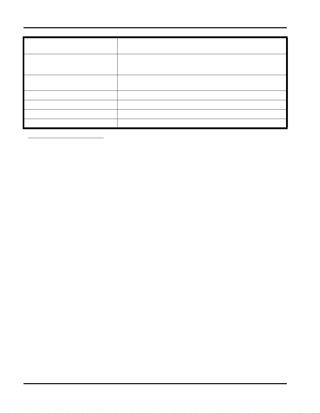
System Overview
The Hitachi VisionBase 8880R Serve r is a high pe rform ance IA-ar chitect ure serve r upgr adeable to an 8-way s erve r
system that has PentiumII Xeon processors. Its features include the following:
Pentium II Xeon: IA32 Microprocessor (400/450MHz, 1/2MB L2 Cache)
•
Windows NT Enterprise Server with high expandability and a 19-inch rack mount system
•
High I/O band width (64 bit PCI bus x 4) with a 16GB memory system
•
High Availability with built-in robustness by hardware redundancies and RAS feature
•
High performance and scalability
•
Joint development with Corol lary and Intel with profusion architecture and additional Hitachi original
•
technology
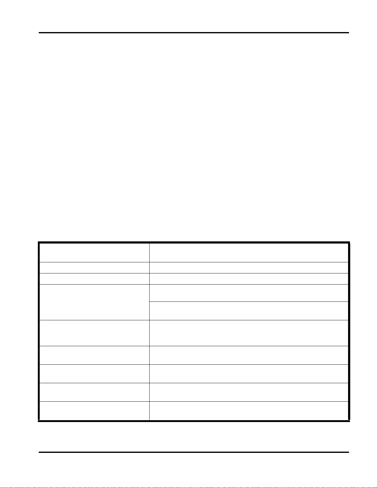
System Specifications
The Hitachi VisionBase 8880R Server system has four (4) independent 64-bit PCI busses.
See the table below for the system specifications.
CPU PentiumII Xeon
400/450 MHz x 8 1/2MB L2 Cache
CPU Bus frequency 100 MHz
PCI Bus frequency 33 MHz
Memory Std./Max.
(4-way Interleave)
Display Contro ll er S3 Trio64 V2/DX (2MB)
Slots 64-bit PCI x 15, 32-bit PCI x 3
Disk Array Mylex DAC960PU (Mylex)
512 MB/16 GB (32 GB with 256MB DIMM)
SSTL SDRAM DIMM
4 Memory boards (2 Standard, 2 Optional)
32 DIMM slots/Memory boards
1280 x 1024 (256 colors) 1024 x 768 (65,536 colors)
800 x 600 (True color), 640 x 480 (True color)
PCI/ISA x 1 (shared), ISA x 1
Ultra Wide-SCSI 3, RAID 0,1,5,7, 0+1 supported
Disk Supports 9GB/18GB HDD (SCA2 interface)
Maximum capacity is 108GB using 18GB HDDs
System Management • System Manager (Hitachi proprietary)
• SVP board (Hitachi Emergency Management board) (Fero
Hitachi Vis ionBase 8880R Server 1
Availab ility)
3
Page 6
Ch 1: Hardware
CPU PentiumII Xeon
400/450 MHz x 8 1/2MB L2 Cache
Bay • 6 SCA2 Disk Bay SAF-TE (Hot-swappable disk bay) compliant SCSI
backplane
• 5.25-inch bay x 3
High Availability Redundant cooling fan
Redundant power supply
Hot Swap HDDs SVP Hardware
Power Supply 3 + 1 Redundant power supply, 550W for each P/S unit
Size 430 (W) x 640 (D) x 756 (H) mm, 17 U ~ Approx. 17" x 25" x 30"
Weight Between 70–100 kg ~ Approx. 175–250 lbs.*
*WARNING: Do NOT attempt to lift or move the server by yourself as phys ical injury may occur.
2 Hitachi VisionBase 8880R Server
Page 7
Ch 1: Hardware
Hitachi Vis ionBase 8880R Server 3
Page 8
Ch 1: Hardware
r
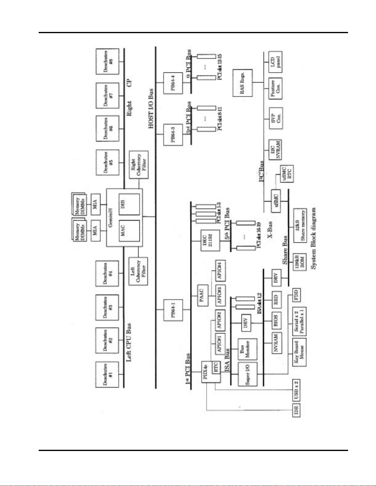
Powering-On the System
Before turning on the system confirm that the main power LED (green), located on the front panel, is illuminated.
If so, you may press the Main Power Switch to boot the system. If the LED is not illuminated you will need to
manually access the indivi dual power suppli es and turn them on in order sta rting wit h Power Supply #1, located on
the far left. See the fi g ures an d directions below to assist you in accessing and turning on the power supplies.
NOTE:
Ensure direct power switch is in the “OFF” or normal position.
HDDs
Power Supply Cove
HDD Bay Door
Remove these 2 screws
located on metal tabs
Figure 1 Accessing the Power Supplies (1)
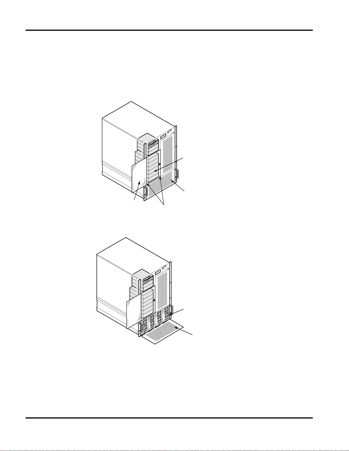
Power Supplies
Power Supply door
folds down
Figure 2 Accessing the Power Supplies (2)
Remove the Power Supply cover by opening the HDD bay door using the key, and then unscrewing and
1.
removing the 2 screws located at the bottom of the HDD bay on the metal tabs. See Figure 1 Accessing the
Power Supplies (1).
Open the Power Supply door by pulling it forward, it folds down to open exposing the power supplies.
2.
4 Hitachi VisionBase 8880R Server
Page 9
Ch 1: Hardware
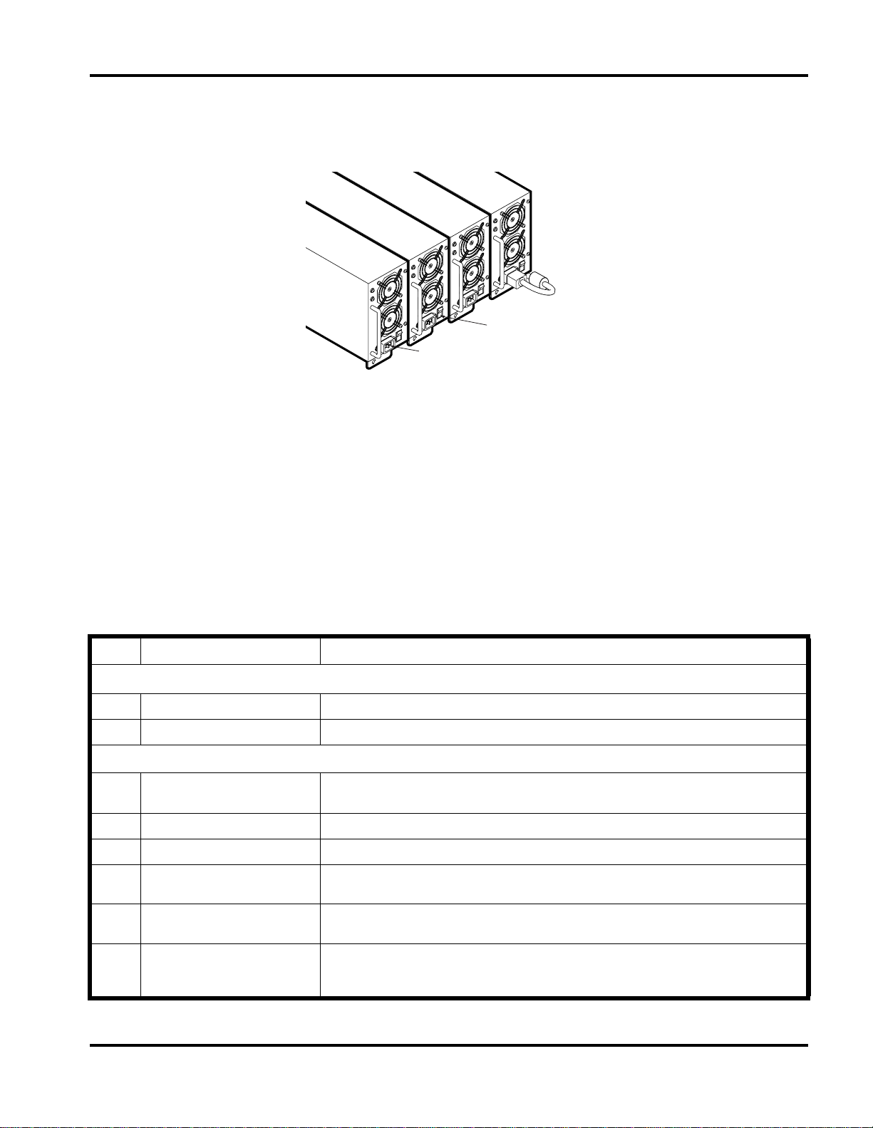
Starting with Power Supply #1 (far right), connect the proper end of each AC power cord into the AC power
3.
receptacle and then to an outside power source. On each power supply press the On/Off Power Supply Switch
to the On position as shown in Figure 3 P/S Receptacle and On/Off Switch.
P/S 1
P/S 2
P/S 3
P/S 4
On/Off Power
AC Input
Switch (TYP)
Receptacle (TYP)
Figure 3 P/S Receptacle and On/Off Switch
Confirm that the Main Power LED is now illuminated.
4.
Close the Power Supply cover and secure it using the original 2 screws. Close the HDD bay door and secure it
5.
using the key.
Turn on the power to the system by pressing the Power Switch located on the front panel.
6.
You may now boot the system by pressing the Main Power Switch on the front panel.
7.
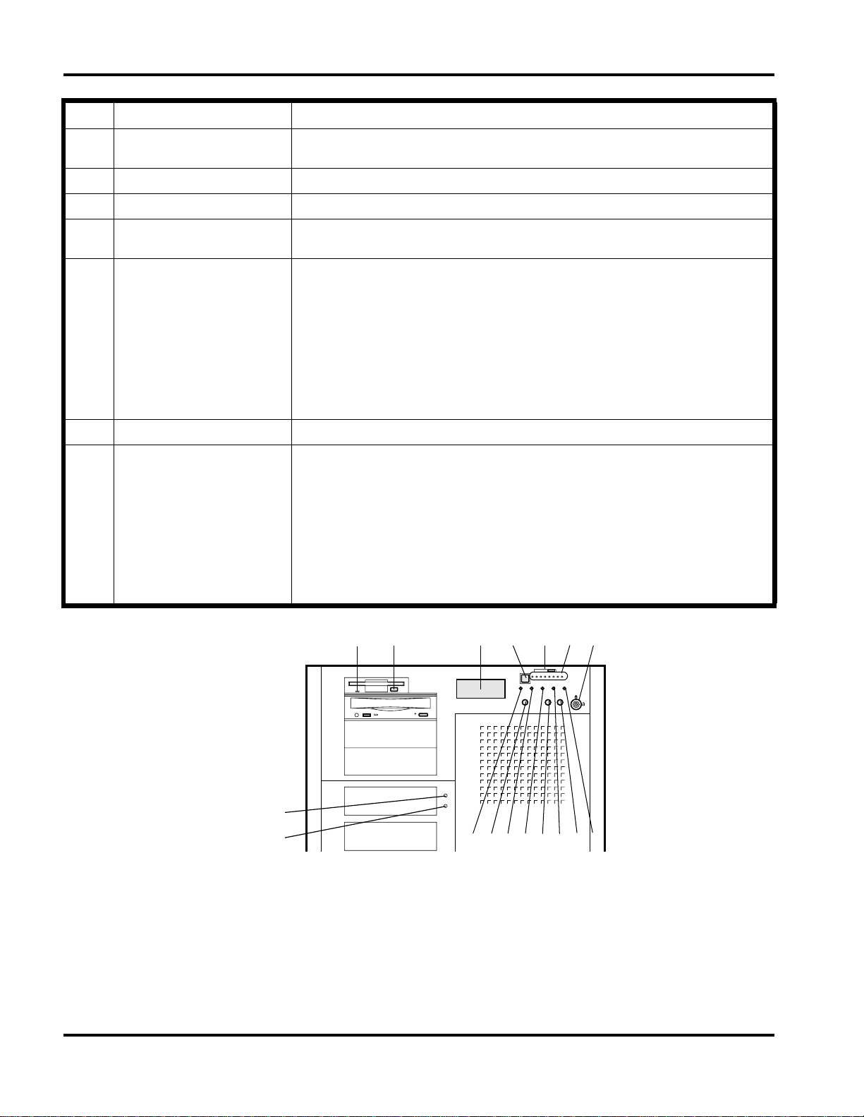
Front Panel
The following table and figure will explain the locations and functions of the front panel controls and indicators.
See Figure 4 Front Panel Detail of the front panel for location of the features listed in the following table.
Item Feature Description
3.5-inch Diskette Drive
A Activity LED When lit, it indi cates the drive is in use.
B Ejecto r b u tto n When pressed, it ejects the diskette.
Front Panel LEDs and Ind ictors
C Front panel LCD It displays information about the system and can also be controlled using the Menu
Switch (I ).
D Main Power Swi tch Press this switch to turn on the power inside the system or to boot the system.
E LCD Contrast/Slider Max brightness only
F CPU Operation This indicator is re lat ed to activ it y in each CPU. When it is flashing it is showing CPU
G Security Lock In the locked position (when the l ock is turned to the left or counte r cl ock-wise) it wil l
H Main Power LED When illuminate d this LED indicates that all of t he system’s AC power connections
activity. (1 LED per CPU)
prevent the syst em Power Switch, keyboard, and mouse from bei ng operational.
are correct, the power supplies are turned on, and the system is receiving direct
current (DC). The system is ready to be activated by the Main Power Switch.
Hitachi Vis ionBase 8880R Server 5
Page 10
Ch 1: Hardware
Item Feature Description
I Menu Switch This switch can select information and opti ons that are displayed on the syst em ’s
LCD.
J Power LED When illuminate d it shows that the system power is on.
K Access LED When illuminate d it shows that SCSI devices are being accessed.
L Buzzer Stop Press this button to turn off the buzzer alarm. This buzzer does not necessarily
indicate syst em error, it may be in a warning st ate.
M Warning LED (yellow) When illuminated it indicates one of the following recoverable errors:
This is only for redundancy cases
• ECC 1 bit
•CPU error
• Memory Bus error
• HDD error
• Temperature is high
• Fan failure
• Power Supply failure
N Reset This Reset is for system maintenance only, and is not a Hard ware Reset Switch.
O Error LE D (r e d) When illuminated it indicates one of the following serious statuses:
• ECC 2 bit
•CPU error
• HDD error
• Temperature is abnormal
• Fan failure
• Power Supply failure
• PCI slot error
• ISA slot error
AB CDEFG
Green
Red
H
IJKLMNO
Figure 4 Front Panel Detail
6 Hitachi VisionBase 8880R Server
Page 11
Ch 1: Hardware
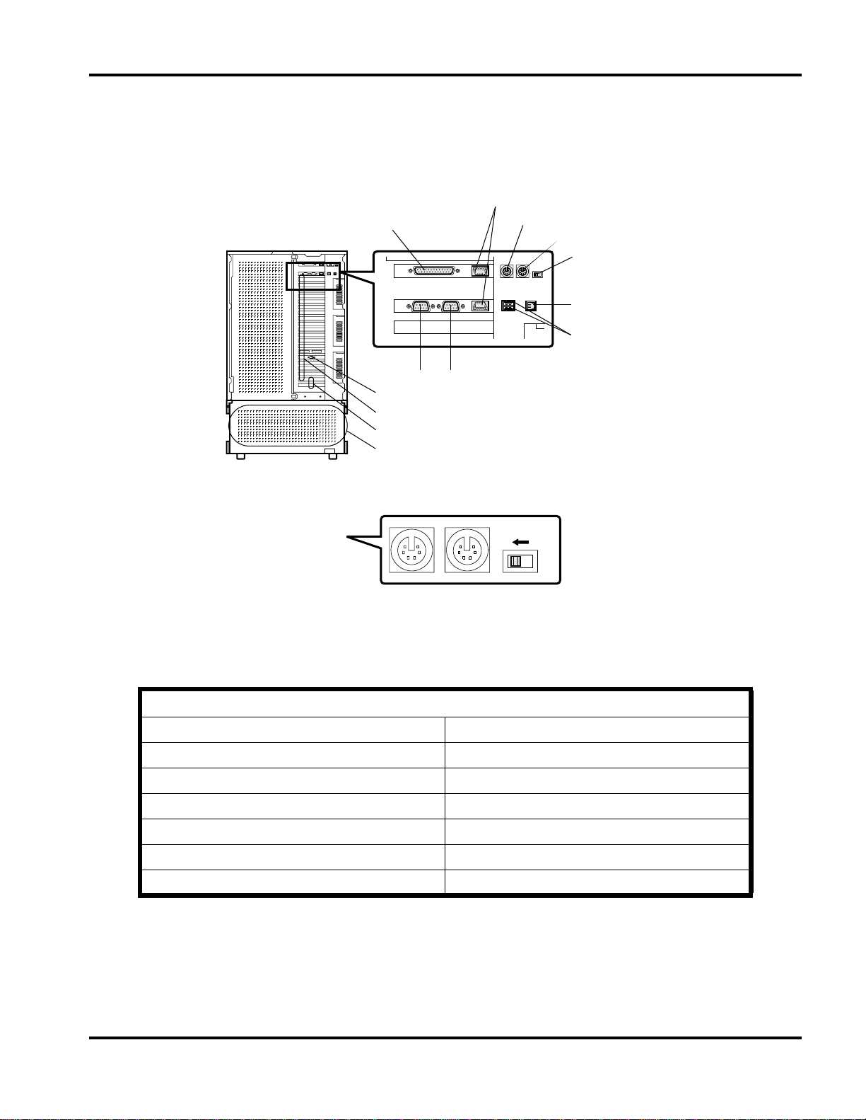
Back Panel
The following t able and figure wil l specify the location of the back panel controls , switches, connecto rs and option
slots.
B
A
FG
J
K
L
M
C
D
E
(See Detail A)
I
H
Figure 5 Back Panel Detail
E
Direct Boot Switch
ON OFF
Detail A
Figure 6 Direct Boot Switch Detail
Server I/O Panel
A. Parallel Interface Connector H. USB Connec tor
B. ICMB Connector See note 1 I. PTL Connecto r (Test connector, not in use)
C. Keyboard Connector J. VGA Interface Connector
D. Mouse Connector K. Option Slots (PCI) 1–19
E. Direct Boot Switch (See Detai l A and note 2) L. Option Slots (ISA) 1–2
F. Serial Interface Connecto r (COM1) M. Power Supply Units 1–4
G. Serial Interface Connector (COM2)
Back Panel Notes:
The ICMB connector (same shape as a conventional ICMB connector) is a
1.
connector
When the Direct Boot Switch is turned On and the system has power, it will allow the system to automatically
2.
. Connect the external disk interface cable to this connector when preparing to use an external disk unit.
Hitachi proprietary interface
boot without pressing the Power Switch manually.
Hitachi Vis ionBase 8880R Server 7
Page 12

Ch 1: Hardware
Removing the Server Panels and Accessing Its Components
It will be necessary to remove the exterior panels of the unit to access internal components. Be sure to rea d and
comply with the Safety Guides before proceeding.
Safety Guidelines
Before you remove the top and side covers of the server, observe these guidelines:
Turn off all peripheral de vices connected to the server.
1.
Turn off DC power in t he server by pres sing the push-button on/off powe r switch on the fr ont panel of the server.
2.
Disconnect AC power to the server by unplugging the alternating current (AC) power cord from each power
3.
supply or wall outlet.
Label and disconnect all peripheral cables attached to the I/O panel on the back of the server.
4.
Provide some electrostatic discharge (ESD) protection by wearing an antistatic wrist strap attached to chassis
5.
ground of the server—any unpaint ed metal sur face—when handling components.
Warnings and Cautions
Only a
inside the server.
qualified service technician
is authorize d to remove the server panels and to access any of the components
Tools and Supplies You Need
Phillips (cross-he ad) screwdriver (#1 bit and #2 bit)
•
Small flat-bladed screwdriver
•
Antistatic wrist str ap (required)
•
NOTE:
Bay Extraction tools are provided with the unit, located on the rear of the chassis, and should remain with
the unit when not in use.
8 Hitachi VisionBase 8880R Server
Page 13
Ch 1: Hardware
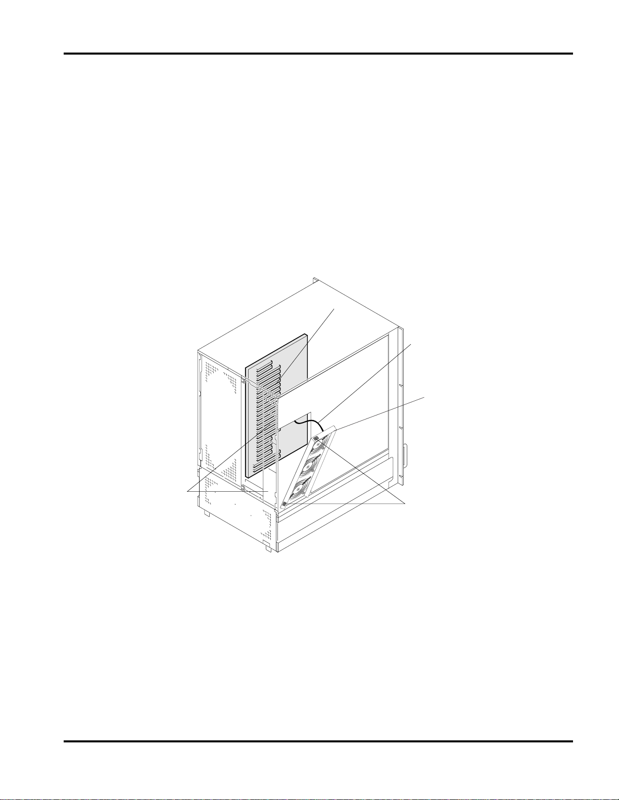
Accessing the PCI Slots
Before you can access the PCI (Peripheral Componen t Interconnect) slots you need to remove the right side outer
panel of the server. Observer an d follow the Safety Guidelines to prepa re the unit for disassembly bef ore proceeding.
Once you have exposed the fan assembly you can proceed as follows. See Figure 7 Accessing the Option Slot s.
Facing the back of the server locate and remove the 2 screws which secure the fan assembly’s left side to the
1.
server chassis.
Disconnect the fan assy cabling from the main board.
2.
Lift the fan assembly straight up by placing your fingers under the front lip of the fan assembly. The fan
3.
assembly is attach ed to the chassis by 2 tab style latches ( shaded). As soon as you have lifted the fan asse mbly
high enough so it is clear of the latch tabs, you may. gently pull the assembly towards you to remove it
completely.
The Option slots (PCI/ISA) are now expos ed.
4.
Option PCI Slot 16 is shared with ISA Slot 2.
5.
Option Board Slots
3. Disconnect the fan wiring
from the main I/O board.
2. Place fingers under the lip
of the assy and pull up gently.
1. Remove the 2 screws
securing the fan assy. 4. Remove the metal fingers (2)
of the latch tab from the chassis
supports and remove fan assy.
Figure 7 Accessing the Option Slots
Hitachi Vis ionBase 8880R Server 9
Page 14
Ch 1: Hardware
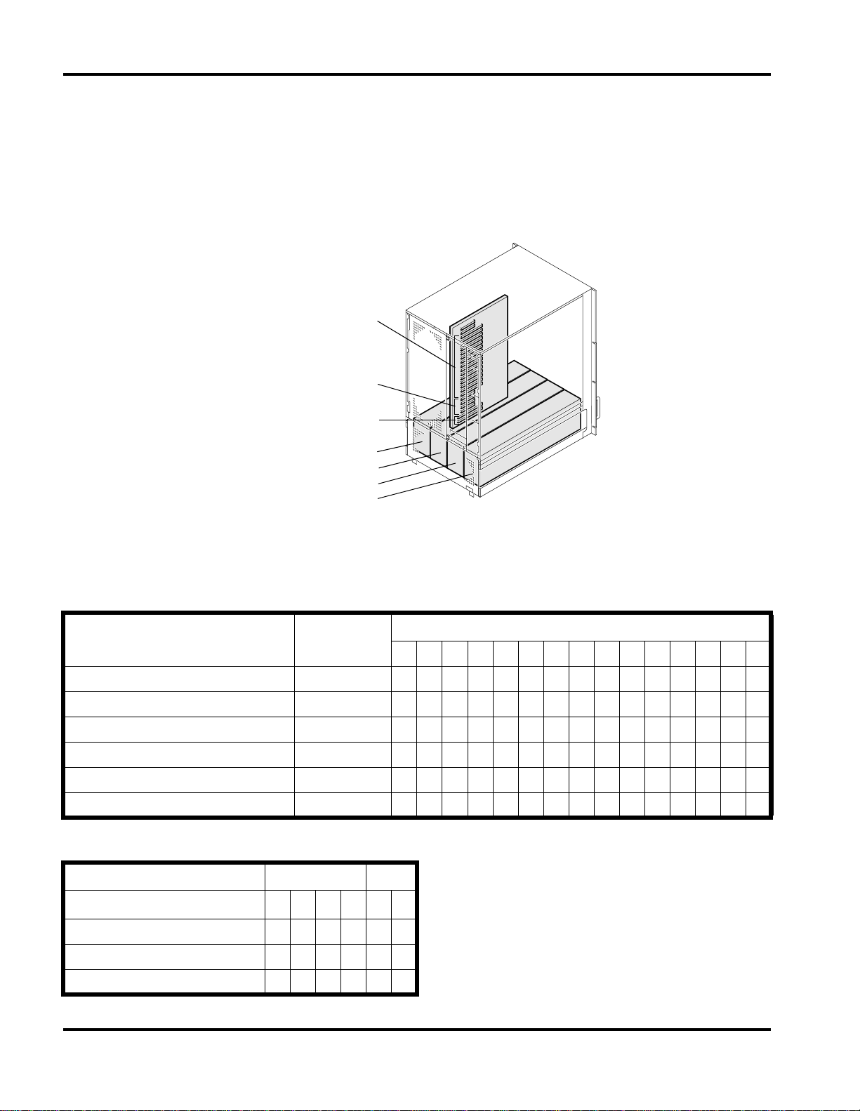
PCI/ISA Option Boards
The I/O baseboard provides 15 64-bit PCI bus master slots (slots 15–1) and 4 32-bit PCI bus master slots
(slots 16–19). They accept any ad d-in PCI and ISA boards or any add-in board that is compatible with an IBM PC
AT or PC XT system (except for an 8-bit drop card that fits only in an 8-bit PC XT connector). Note: PCI Slot 16
and ISA Slot 1 share a common chassis I/O expansion slot. You can use the slot for either the PCI or the ISA, but
not both. See Figure 8 Option Slots for slot location details.
Option Slot (PCI) #15 (top)
through
Option Slot (PCI) # 1
Option Slot (PCI) #19 (top)
through
Option Slot (PCI) # 16
Option Slot (ISA) # 1
Option Slot (ISA) # 2
Power Supply Unit # 1
Power Supply Unit # 2
Power Supply Unit # 3
Power Supply Unit # 4
Figure 8 Option Slots
Hitachi recommends the following configuration for installing option boards.
Usage: “X”: recommend, “N”: don’t install
Maximum
Installation #
VGA board; S3 Trio64 V2/DX 1 N N N N N N N N N N N N N N X
SCSI board; Symbios SYM8751SP 4 N N N N N N N N X X X N N X N
Disk array controller; Myl exDAC960PU 3 N N N X N N N X N N N X X N N
Fiber Channel 1 X X X N X X X N X X X N N N N
Ethernet card (100/10M) 12 X X X X X X X X X X X X N N N
Gigabit Ether net card (1000M) 9 X X X X X X N N X X X N N N N
15 14 13 12 11 10 9 8 7 6 5 4 3 2 1
PCI (64 bit)
Usage: “X”: recommend, “N”: don’t install
PCI (3 2 bit ) ISA
19 18 17 16 1 2
Multi communication board X X X X N N
ISDN board X X X X N N
SVP board; Hitachi Proprietary X X X X N N
10 Hitachi VisionBase 8880R Server
Page 15
Ch 1: Hardware
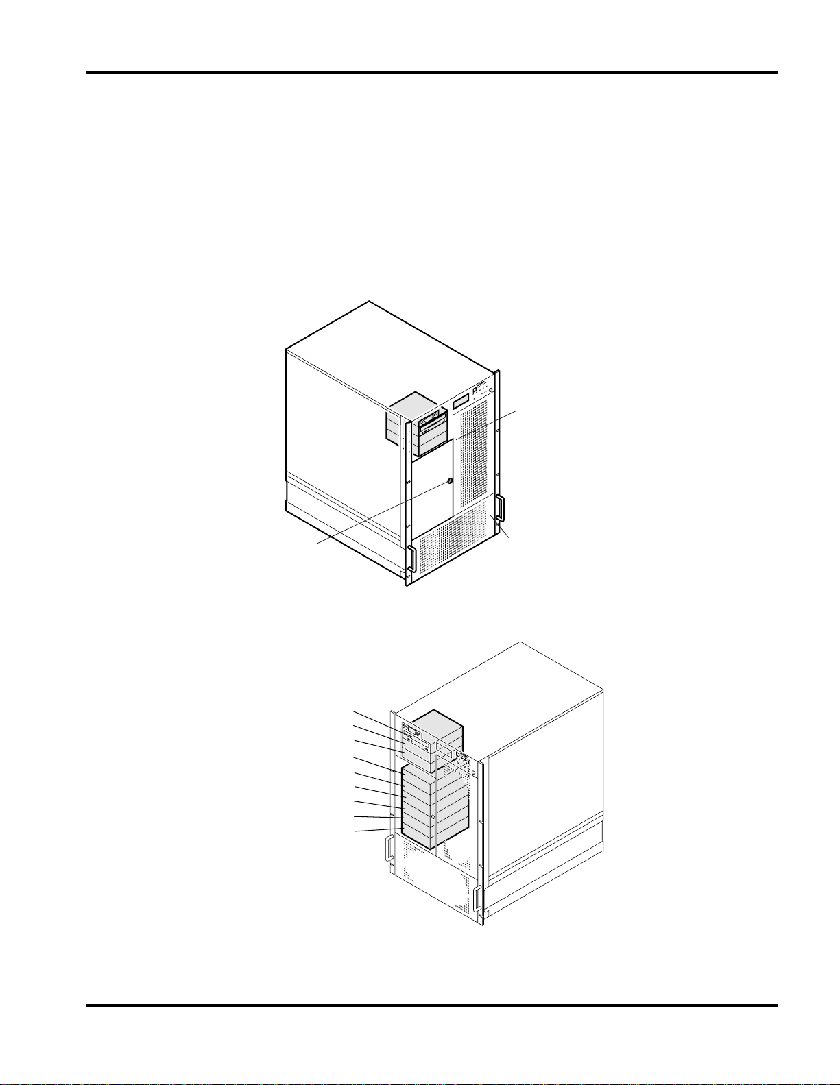
Hard Disk Drives
SCSI SCA Hard Disk Drives
The server supports up to 6 SCSI SCA2 (80-pin) hot-swappa ble SAF-TE compliant backpl ane type hard disk drives
and can be in stalled in Device Bays 1 through 6 as shown in Figure 10 Hard Disk Drive Bays. As shipped from the
supplier the server may not contain any drives. Contact your Hitachi PC Customer Service and Support
Representative for a list of approved drives that can be installed in the server.
To access the Hard Disk Drive bay unl ock the door by insertin g the key and turning to the lef t, or counter clockwis e.
Accessing the HDD bay and device locations are referenced in the following Figures.
Cooling Fan
Access Door (Ref)
HDD door and
lock location
Device Bay #7
Device Bay #8
Device Bay #9
Device Bay #1
Device Bay #2
Device Bay #3
Device Bay #4
Device Bay #5
Device Bay #6
Power Supply
Access Door (Ref)
Figure 9 Accessing the Hard Disk Drives
Figure 10 Hard Disk Drive Bays
Hitachi Vis ionBase 8880R Server 11
Page 16
Ch 1: Hardware
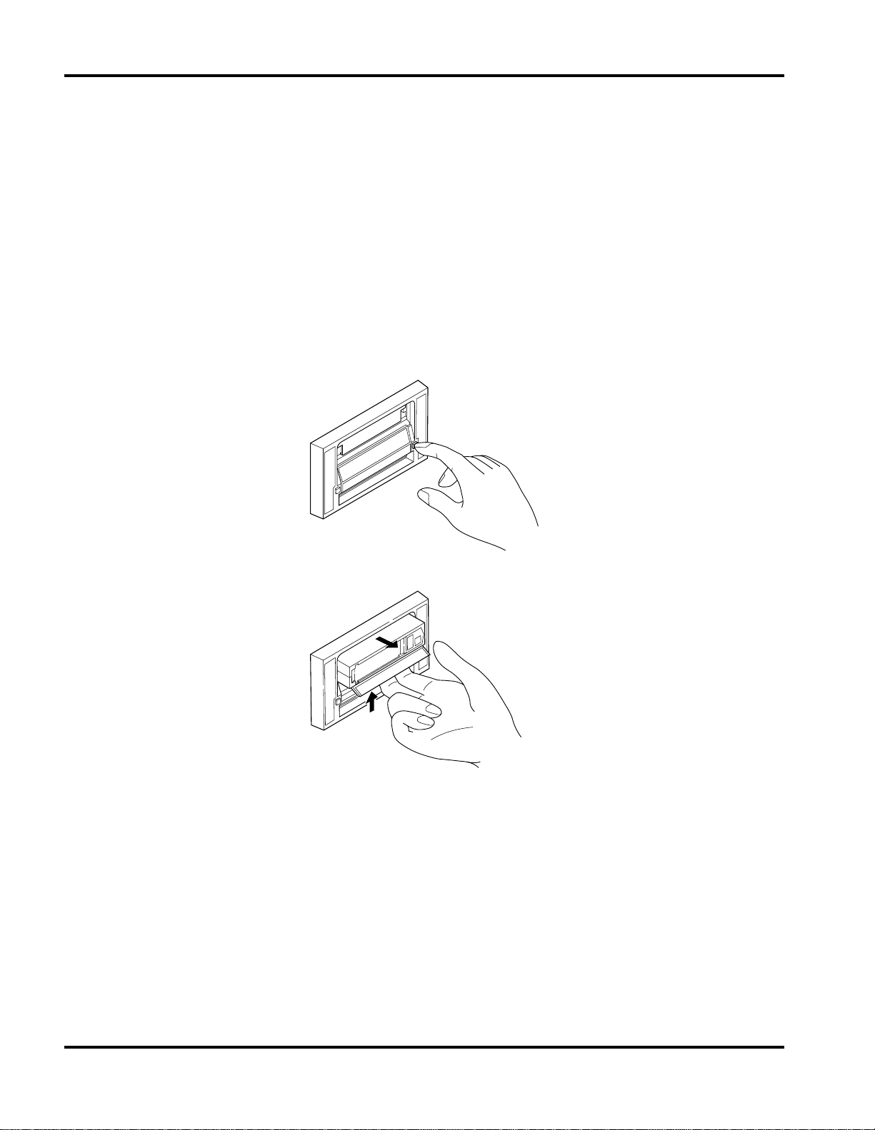
Installing/Swapping a HDD
The HDD Bay door l ocation provides air flow and easy access to the drive s and allows easy hot-swapping of drives
in and out of these bays without shutting down the server.
By installing a Redundant Array of Independen t Disks (RAID) controller board on the I/O baseboard, RAID
software, and SCSI hard disk drives in the hot-d ocking bays, you can easily set up RAID applications.
To remove or hot swap a HDD device follow these steps:
Pull down on the front lever (or handle) of the HDD Bay cage and
1.
drive stops sp inni n g comp l etel y
After the drive has stopped spinning pull the assembly toward you to fully disengage the drive from the
2.
.
backplane connector.
Carefully slide the ass embly out of the bay, and place it on an antistatic surface. Proceed to ste p 4 if you are
3.
installing or repl acing a HDD.
wait approximately 30 seconds until the
Figure 11 Removing/Installing a HDD
Insert the HDD into a carrier and sec ure it into position with 4 screws as shown in Figure 12 Mounting the HDD
4.
Carrier.
Orient the carrier and drive assembly in front of the hot-docking bay guide and make sure that it is placed
5.
correctly into the gui de rai ls to avoid damage.
Fit the mounting pins, located on each side of the HDD, into the inside grooves of the HDD Bay’s lever.
6.
After the mounting pi ns ar e seate d in the l ever groove s pul l up on the lever. This wil l push the HDD into its sl ot.
7.
Firmly press the front of the asse mbly int o the bay until the drive docks with the hot-docking backpla ne
8.
connector
12 Hitachi VisionBase 8880R Server
Page 17
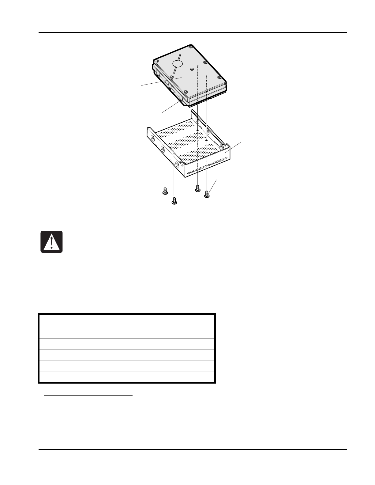
HDD
HDD Position Pins
Ch 1: Hardware
HDD Carrier
4 Mounting Screws
Figure 12 M o unt in g the HDD C arri e r
Some specific h ard disk dr ive designs requ ire el ectri cal i sola tion of t he d rive f rom t he chassi s or other
ground paths. These drives are usually clearly labeled with this requirement on the drive. Failure to
isolate this type of drive from the ground path will result in unpredictable operation of the drive,
including sever ely impacted performance and data corruption.
Optional Devices
Additional storage devices, such as CD-ROMs and DATs can be installed in Device bays 7, 8 and 9.
Hitachi recommends the followi ng configur ation for any additional storage dev ices tha t you may install.
Usage: “X”; recommend, “N”; don’t install
Device Bay #
7 8 9
Internal CD-ROM x X N
Internal DAT N X X
Internal DAT Changer N X
Internal DLT* N X
* Internal DLT devices require their own SCSI boards and cabling. Do not use the same cabli ng as the Internal CD-ROM.
Hitachi Vis ionBase 8880R Server 13
Page 18
Ch 1: Hardware
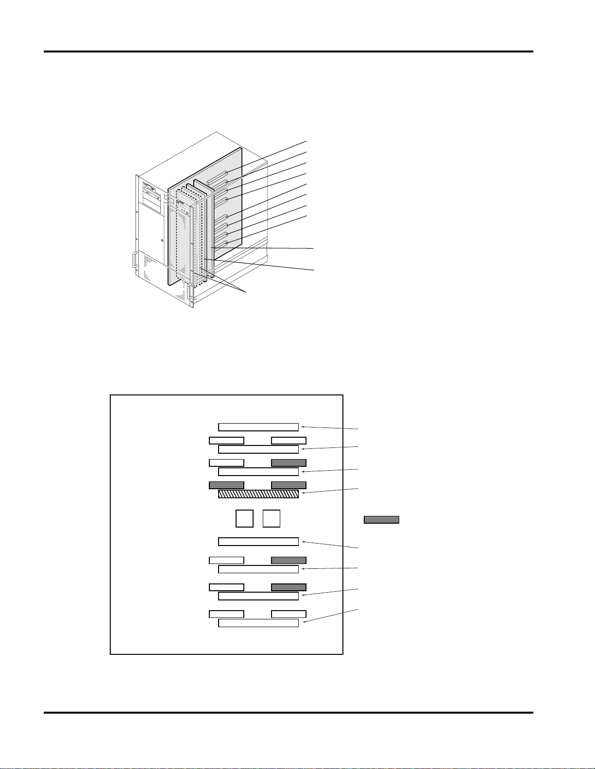
CPU
This chapter d escr ibes the CPU baseboard and shows how to set the jumpers. Note: CPUs need to be installed with
VRMs (Voltage Regulator Module).
Processor slot #4
Processor slot #3
Processor slot #2
Processor slot #1
Processor slot #5
Processor slot #6
Processor slot #7
Processor slot #8
Memory Expansion board #1
(Memory slot x 32)
Memory Expansion board #2
(Memory slot x 32)
Memory Termination Cards
(Option Memory Slot #3, 4)
Figure 13 Memory and CPU Slots
Each CPU is numbered and corresponds to a numbered VRM. Install the CPUs in the order shown below in
Figure 14 CPU/VRM Installation Detail. Note: This detail is for one CPU instal led, minimal configuration.
Processor Slot #4
VRM #3
VRM #2
VRM #1
VRM #5
VRM #6
VRM #7
VRM #4
VRM #8
Processor Slot #3
Processor Slot #2
Processor Slot #1
= Default VRM
setting
Processor Slot #54
Processor Slot #6
Processor Slot #7
Processor Slot #8
Figure 14 CPU/VRM Installation Detail
14 Hitachi VisionBase 8880R Server
Page 19

Ch 1: Hardware
Memory
The Memory Architecture of this system is a 4 way interleave. The memory needs to be installed in se ts of 4. Do not
attempt to install memory sets before removing the board from the unit and properly grounding yourse lf , the
memory expansion board, and the memory sets to avoid ESD damage.
There are two memory expansion boa rds per syste m as a standard config uration. Eac h memory expansion board c an
accommodate 2 sets of memory DIMMs, A and B. Each set has sixteen DIMMs. Thus there are total of four sets of
DIMMs per standard system. The memory configurati on is 4 ways interleave and requires installation of
four DIMMs at a time. Base configuration comes with 1GB (128MB x 8 pcs) of memory using 128 MB of DIMMs.
The table below summarizes the memory configurations:
Total Memory: 4.0GB
X
X
X
X
X
X
X
X
X
X
X
X
X
X
X
X
X
X
X
X
X
X
X
X
X
X
X
X
X
X
X
X
Total Memory: 3.5GB
X
X
X
X
X
X
X
X
X
X
X
X
X
X
X
X
X
X
X
X
X
X
X
X
X
X
X
X
Total Memory: 3.0GB
X
X
X
X
X
X
X
X
X
X
X
X
X
X
X
X
X
X
X
X
X
X
X
X
Total Memory: 2.5GB
X
X
X
X
X
X
X
X
X
X
X
X
X
X
X
X
X
X
X
X
Total Memory: 2.0GB
X
X
X
X
X
X
X
X
X
X
X
X
X
X
X
X
Total Memory: 1.5GB
X
X
X
X
X
X
X
X
X
X
X
X
(Defaul t Configurat io n)
Total Memory: 1.0GB
X
X
X
X
X
X
X
X
Total Memory: 512MB
X
X
X
X
DIMM Socket Number:
1
1
1
1
2
2
2
2
3
3
3
3
4
4
4
4
5
5
5
5
6
6
6
6
7
7
7
7
8
8
8
8
DIMM Socket Sets:
A
B
A
B
A
B
A
B
A
B
A
B
A
B
A
B
A
B
A
B
A
B
A
B
A
B
A
B
A
B
A
B
Board Number
Memory Expansion
1
1
2
2
1
1
2
2
1
1
2
2
1
1
2
2
1
1
2
2
1
1
2
2
1
1
2
2
1
1
2
2
Hitachi Vis ionBase 8880R Server 15
Page 20

Ch 1: Hardware
2A
15
10
7A
6A
11
14
3A
4A
13
12
5A
8A
9A
16
1A
1B
16
9B
8B
5B
12
13
4B
3B
14
11
6B
7B
10
15
2B
System Unit—Right Side
Set A
Memory Riser Board
Connector
Front
Side
Set B
CPU
Memory Expansion Board #1
Memory Expansion Board #2
Memory Expansion Board #3 (optional)
Memory Expansion Board #4 (optional)
Figure 15 Memory Board Slot Location
The system supports the following spec ifications for memory DIMMs:
Support DIMM Description
Memory DIMM 128MB DIMMs
256MB DIMMs
Error correction ECC
16 Hitachi VisionBase 8880R Server
SDRAM (SSTL interface, DIMM)
Buffer
Page 21

Jumper Settings
Below is the default jumper setting for the syst em board, as shipped from the factory.
JP31 JP27
JP31
JP27
Ch 1: Hardware
VRM #3
VRM #2
VRM #1
JP1 JP21
= short jumper
JP24 JP29 JP25
JP01
JP24
JP29
JP25
VRM #5
VRM #6
VRM #7
Figure 16 S ys tem Boa rd De fa ult J umper Settings
VRM #4
VRM #8
Hitachi Vis ionBase 8880R Server 17
Page 22

Ch 1: Hardware
Below are the default switch settings for the I/O board, as shipped from the factory.
ISA #1 (Shared)
ISA #2
PCI #16
PCI #17
PCI #18
DEC21152
PIIX4e
SW1
SW2
SW3
SW4
PCI #19
PCI #1
Super I/O
PC87307
SW5
SW6
SW7
APIC
APIC
APIC
APIC
BIOS
DS1230
NVRAM
DS1230
uSMC
uSMC
Firmware
uSMC
8.
SEG1
PCI #15
8.
SEG2
Riser
Connector
LED5
-12V
LED4
-5V
LED3
+3.3V
LED2
+5V
LED1
+12V
SW1
12345678
SW2
SW3
12345678 12345678 12345678
SW4
SW5
ON
OFF
Figure 17 I/O Board Switch Settings
ON
OFF
SW7SW6
18 Hitachi VisionBase 8880R Server
Page 23

Ch 2: System Environment Setting
2:System Environment Setting
When you install the system or change the system configur ation, it is necessary to execute setup operations and to
make configuration set tings with the system setup uti lity . Note that if these setti ngs are not done , you cannot inst all
or operate your operating system and applications.
Before Operations
Be sure to read this section before conducting system environment settings.
Flow of System Environment Setting
When you initially use the sy stem or after you changed the syste m configur ation (for exampl e, by inst alling an ISA
board), you need to conduct system environment setting. There are two capabilities provided for system
environment setting, the Setup Menu and the ISA Configur ation Utility (ICU), which must be executed in the
following procedure:
Start of the system environment setting
Turn off the system equipment,
plug off the power cord,
and wait 30 seconds
Change the system configuration
Connect the power cord
with the system equipment,
and turn on power
Execute the Setup Menu
Create backup disks for the ISA
configuration utility disks
Execute the ISA configuration utility
End of the system environment setting
Built-in devices must be added or exchanged by maintenance personnel only. Be sure to avoid
removing the cover and installing/removing built-in devices. Otherwise, operation of the equipment
shall not be guaranteed.
Hitachi Vis ionBase 8880R Server 19
Page 24

Ch 2: System Environment Setting
What You Can Do with the Sy stem Envi ronment Setting
In the system environment setting, you use the BIOS setup (Se tup Menu below) and the ISA configuration utility
(ICU below) to create an environment in which the system equipment is usable.
Outline of the Setup Menu
In the Setup Menu, you can set up the following:
Main Menu
•
Setting date and time for the built-in timer
-
Type of floppy disk drive
-
Type of IDE hard disk drive (unsupporte d)
-
Checking for keyboard at startup
-
System information (checking only)
-
Memory capacity (checking only)
-
Advanced Menu
•
Resetting the setup data
-
Setting initial diagnosis for ROM
-
Setting PCI
-
Setting I/O devices
-
Console redirection ( unsupported)
-
Setting extended multiprocessor configuration table
-
Setting I/O APIC mode
-
Setting memory gap
-
Setting parity check for PCI
-
Setting memory test
-
Setting 4GB or more caching for main memory
-
Setting large-capacity disk access (unsupported)
-
Setting light cache for disk (unsupported)
-
Setting speaker volume
-
Setting USB controller
-
Security M enu
•
Setting administrator password
-
Setting user password
-
Whether or not to use password at startup
-
Boot Menu
•
Setting priority for boot devices
-
Exit Menu
•
Exiting the Setup Menu
-
Loading setup data
-
Setting defaults
-
20 Hitachi VisionBase 8880R Server
Page 25

Ch 2: System Environment Setting
Outline of ISA Configuration Utility (ICU)
In the ICU you can display or set the following:
File Menu
•
Saving the settings and exit ing the ICU
-
Configure Menu
•
Adding, changing, and delet ing ISA boards
-
View Menu
•
Displaying resource allocation status for the system and extended boards
-
Advanced Menu
•
Locking the setting for Plug and Play board and calling/saving ICU setup data (image)
-
Notes on Use
Setting for Each Board
Depending on the extended board, there are restrictions on setting for IRQ and ROM addresses. See the manual for
each board .
PCI Bo ard
If you use Windows NT, use “Auto Select” in the Setup Menu to set IRQ setting values for extended boards
conforming to the PCI specifications.
ISA Bo a rd
When setting system enviro nment for an ISA board, check whethe r or not the disk at tached to the board cont ains the
CFG file. The CFG files for a communication board (PC-CH2100) and an ISDN board set (PC-SHT4840-IS) are
contained in the ISA configuration utility disk.
If no CFG file is provided, take one of the following actions:
Obtain a CFG file from the manufacturer or vendor of the board.
•
Create a CFG file by yourself.
•
NOTE:
Hitachi PC assumes no responsibility for failures resulting from the use of PCI or ISA boards not supported
by Hitachi.
Hitachi Vis ionBase 8880R Server 21
Page 26

Ch 2: System Environment Setting
Setup Men u
The Setup Menu allows you to make basic settin gs for the sys tem equipment . The s ettings are sto red i n the mem ory
of the system equipment.
Flow of the Setup Menu O peration
The flow of the Setup Menu operation is as follows:
Start the Setup Menu
Main Menu
Advanced Menu
Security Menu
Boot Menu
Exit Menu
Submenus
IDE Menu (unsupported)
System Information
PCI Configuration
I/O Device Configuration
Console Redirection
Hard Drive
Esc
Esc
Esc
key
key
key
You can use and keys to switch between menus (b etween Main and Advanced, between Advanced and
←
Security, between Security and Boot, and between Boot and Exit). Use the key to return from a submenu to
→
Esc
the original menu.
22 Hitachi VisionBase 8880R Server
Page 27

Ch 2: System Environment Setting
Starting the Setup Menu
The Setup Menu, stored in the ROM of the system equipment, must be started in the following way:
Power the system equipment.
1.
While “Press <F2> to enter SETUP” is being displayed, press the
2.
The Setup Menu starts and the Main menu is displayed.
F2
key.
Main Advanced Security Boot Exit
System Time :
System Date :
Legacy Diskette A :
Legacy Diskette B :
Primary Master :
Primary Slave :
Network Server
System Information
System Memory
Extended Memory
F1 Help
↑↓ Select Item
←→ Select MenuESC Exit
PhoenixBIOS Setup Utirity
[HH:MM:SS]
[MM/DD/YYYY]
1
/
[1.44/1.25MB 3 "]
[Disabled]
[None]
[None]
[Disabled]
xxxKB
xxxMB
-/+ Change Values
Enter Select
2
Item Specific Help
F9 Setup Defaults
F10 Save and Exit Sub-Menu
Figure 18 Entering Setup Menu
If the operating system has alre ady started befor e the key is pressed, terminate the OS and then resta rt the
F2
system equipment. Some type of OS, such as Windows NT, requires spe ci al operation such as shutdown.
Check the manual of your OS.
Hitachi Vis ionBase 8880R Server 23
Page 28

Ch 2: System Environment Setting
Setup Menu Screen
Confi guration of the Setup Menu Screen
When the Setup Menu is started, a screen similar to the fol lowing is displayed:
Main Advanced Security Boot Exit
1
System Time :
2
System Date :
Legacy Diskette A :
Legacy Diskette B :
Primary Master :
Primary Slave :
Network Server
System Information
System Memory
Extended Memory
F1 Help
↑↓ Select Item
←→ Select MenuESC Exit
PhoenixBIOS Setup Utirity
[HH:MM:SS]
[MM/DD/YYYY]
1
/
[1.44/1.25MB 3 "]
[Disabled]
[None]
[None]
[Disabled]
xxxKB
xxxMB
-/+ Change Values
Enter Select
2
Item Specific Help
F9 Setup Defaults
F10 Save and Exit Sub-Menu
3
4
Figure 19 Setup Menu Sc ree n C on fig ur at ion
Menu bar
1.
← →
Use or key to move the cursor to select the menu (Main, Advanced, Security, Boot, or Exit).
Setting screen
2.
Used to set each setting items. Move the curs or to each of the setting items marked , then press the
key. The submenu is displayed.
Help
3.
The help information for the selected setting item is automatically displayed.
Key guidance
4.
The usage of each key is displayed.
Enter
24 Hitachi VisionBase 8880R Server
Page 29

Operating the Keys on the Setup Menu
In the Setup Menu, the following key operations are all owed.
Key Function
Ch 2: System Environment Setting
↑
↓
Page
Up
,
Home
Page
Down
,
End
–
, (Ten Key)
F5
, (Ten Key)
F6
+
←
→
Enter
F9
F10
, + *
Esc Alt X
, + *
Esc Alt H
Moves the cursor upward on the setting screen.
Moves the cursor downward on the setting screen.
Moves the cursor to th e top of the setting screen.
Moves the cursor to the bottom of the setting screen.
Decreases the setting value by 1.
Increases the setting value by 1.
Moves the cursor to th e lef t on the menu bar .
Moves the cursor to th e ri ght on the menu bar .
Displays the submenu. Executes the command.
Loads the default .
Saves the settin gs and exits the Setup Menu.
Exits the submenu.Moves to the Exit menu.
Displays an explanatory screen for key operations.
* + (or ) means pressing (or ) key while holding down t he key.
Alt X H X H Alt
Hitachi Vis ionBase 8880R Server 25
Page 30

Ch 2: System Environment Setting
F10
Steps for Setting the Setup Menu
When the Setup Menu is started, the Main menu is displayed.
Check the settin g for each se tting it em. If the h ardware conf igu ration dif fers from the sett ings o n the scr een, se e
1.
“What You Can Do on the Main Menu” on page 26 to change the settings. Use
setting item, and then use or
Move the cursor to a setting item marked and press
2.
+
–
key to change the settings.
Enter
key. The submenu on the Main menu is
displayed.
or key to select the
↑
↓
Change the settings as required, and then press
When you move the cursor to “Advanced”, the Advanced menu is displayed. Each item marked has a
3.
key to return to the Main menu.
Esc
submenu.
See “What You Can Do on th e Advanced Menu” on pa ge 28 if necessary to change the s ettings on the Adva nced
menu and its submenus, then return to the Main menu.
Moving the cursor to “Securit y” to displ ay the Security menu.
4.
Moving the cursor to “Boot” displays the Boot menu.
5.
See “What You Can Do on the Boot menu” on page 34 if necessary to set up the Boot menu, and the n return to
the Main menu.
When you finished changing the settings, press the Exit or
6.
key to exit the Setup Menu. See “What You
Can Do on the Exit Menu” on page 35.
Before exiting the Setup Menu, insert ISA Configuration Utility DISK1 into the floppy disk drive. This is
because here in this case the ICU is executed aft er the Setup Menu exits. For details, see “ICU (ISA
Configuration Utility)” on page 50.
What You Can Do on the Main Menu
Main Advanced Security Boot Exit
System Time :
System Date :
Legacy Diskette A :
Legacy Diskette B :
Primary Master :
Primary Slave :
Network Server
System Information
System Memory
Extended Memory
PhoenixBIOS Setup Utirity
[HH:MM:SS]
[MM/DD/YYYY]
[1.44MB 3½"]
[Disabled]
[None]
[None]
[Disabled]
xxxKB
xxxMB
Item Specific Help
F1 Help
↑↓ Select Item
←→ Select MenuESC Exit
-/+ Change Values
Enter Select
F9 Setup Defaults
F10 Save and Exit Sub-Menu
Figure 20 Main Menu Screen
26 Hitachi VisionBase 8880R Server
Page 31

Ch 2: System Environment Setting
System Time and System Date
Set the date and time for the built-in timer.
System Time HH : MM : SS, where HH = Hours (in 24-hour system), MM = Minutes, and SS = Seconds.
•
System Date MM / DD / YYYY, where MM = Month, DD = Day, YYYY = Year (in 4 digits)
•
To move the cursor within the System Time or the S ystem Dat e a rea, press key, or press key whil e
holding down key, or press key.
Legacy Diskette A,B
Specify the type of the floppy di sk drive connect ed. Choose from among the f ollowi ng types. Write down an d store
the settings for each drive.
Disabled (default for Legacy Diskette B)
•
360KB,5¼" (unsupported)
•
1.2MB,5¼" (unsupported)
•
720KB,3½"
•
1.44MB,3½" (default for Legacy Diskette A)
•
Primary Master (Slave)
These areas are for se tting IDE hard disk. Because the Hitachi VisionBase 8880R Server do es no t support IDE, do
not change the settings.
Type:
•
Auto
Multi-Sector Trans fers
•
Disabled
LBA Mode Control
•
Disabled
32 Bit I/O
•
Enabled
Transfer Mode
•
Standard
Ultra DMA Mode
•
Disabled
Shift Enter
Do not enter any value in 360KB,5¼" and 1.2MB,5¼", which are unsupported.
Tab Tab
NOTE:
Hitachi Vis ionBase 8880R Server 27
Because no IDE equipment is installed, “None” is displayed in the Primary Master and Primary Slave
areas.
Hitachi products do not support IDE hard disks. Hitachi PC does not guarantee performance if an
IDE hard disk of another m ake is used.
Page 32

Ch 2: System Environment Setting
Network server
Specify whether or not to check for keyboard at the time of syste m startup. Leave the defaul t setting “Disa bled” as is.
Disabled (default )
•
Enabled
•
System Information
Information about the system equipment is displayed.
System Memory, Extended Memory
The memory capacity recognized at startup is automatically displayed.
NOTE:
If the memory capacity displayed is less than the actual memory capacity, contact the maintenance
personnel.
What You Can Do on the Advanced Menu
Main Advanced Security Boot Exit
Reset Configuration Data [No]
Execute ROM Diagnostic [No]
PCI Configuration
I/O Device Configuration
Console Redirection
Ext MP Configuration Table [Disabled]
I/O APIC Mode: [Single]
Enable memory gap: [Disabled]
PCI Data Parity: [Enabled]
Standard Memory Test: [Enabled]
WinNT 4.0 Install Mode: [Disabled]
Caching Above 4GB: [Disabled]
Large Disk Access Mode: [DOS]
Disk Write Cache: [Enabled]
Spealer volume: [High]
USB Controller: [Enabled]
F1 Help
Reset Configuration Data
↑↓ Select Item
←→ Select MenuESC Exit
Figure 21 Advanced Menu Screen
PhoenixBIOS Setup Utirity
-/+ Change Values
Enter Select
Item Specific Help
F9 Setup Defaults
F10 Save and Exit Sub-Menu
Used to specify whether or not to clear the configuration data. Be sure to leave the default setting “No” as is.
No: Not to clear (default)
•
Yes: To clear
•
Execute ROM Diagnostic (Unsupported)
Used to specify whether or not to conduct initial diagnosis for ROM. Be sur e to leave the default setting “No” a s is.
No: Does not conduct initial diagnosis (d efault).
•
Yes: Conducts initial dia gnosis.
•
NOTE:
28 Hitachi VisionBase 8880R Server
“Reset Configuration Data” and “Execute ROM Diagnostic” are used solely for maintenance purposes.
These two areas shall not be changed. Hitachi PC assumes no responsibility for any failures or
inconveniences caused by changed va lues in these areas.
Page 33

Ch 2: System Environment Setting
PCI Configuration
Select Resources
Specify the resource to be assigned to the PCI slot (inte rrupt level). In ordinary circ umst ances, use the default.
PCI IRQ line 1, PCI IRQ line 2, PCI IRQ line 3, PCI IRQ line 4
•
Auto: Default
3
4
5
7
9
10
11
12
14
15
NOTE:
Current R eso ur ces
The resource (interrupt level) currently assigned to the PCI slot is displayed.
If some resource settings are incorrect, an asterisk “*” is attached to the item, and a message is
displayed at the bottom of the screen. Recheck the setting.
The correspondence between PCI IRQ lines and PCI slots is as follows:
Line 1 corresponds to slots 7, 11, 15, and 19
Line 2 corresponds to slots 1, 4, 8, 12, and 16
Line 3 corresponds to slots 2, 5, 9, 13, and 17
Line 4 corresponds to slots 3, 6, 10, 14, and 18
I/O Device Configuration
Serial port 1, 2
Used to set built-in serial ports 1 and 2 (built -in COM ports 1 and 2). In ordinary circumstances, use the default
settings.
Serial ports 1 and 2
•
Disabled
Enabled (default)
Base I/O address/IRQ
•
3F8/IRQ 4: (default for seria l por t 1) 2F8/IRQ 3: (default for seria l por t 2) 3E8/IRQ 4 2E8/IRQ 3 3F8/IRQ 11 3E8/IRQ 10 2F8/IRQ 11 2E8/IRQ 10
NOTE:
Hitachi Vis ionBase 8880R Server 29
Make sure that the settings in Base I /O address/IRQ for s erial port 1 do not overl ap with those for serial port 2.
Page 34

Ch 2: System Environment Setting
Parallel port
Used to make settings for the built-in parallel port. In ordinary circumstances, use the default settings.
Parallel port
•
Disabled
Enabled (default)
Mode
•
Output only (default)
Bi-directiona l
EPP
ECP
Base I/O address
•
378 (default) 278 3BC Interrupt
•
IRQ5
IRQ7 (defau lt)
DMA channel
•
DMA1
DMA (default)
NOTE:
Floppy disk controller
Used to make settin gs for the bu ilt-in floppy disk d rive controlle r. In ord inary circumsta nces, use the default settings.
Floppy disk controller
•
Disabled
Enabled (default)
Local Bus IDE adapter
Used to make settings for the IDE controller. In ordinary circumstances, use the default settings.
Local Bus IDE adapter
•
Disabled
Enabled (default)
NOTE:
PS/2 Mous e
Used to make settings for the mouse. In ordinary circumstances, use the default setting “Enabled”.
PS/2 Mouse
•
Disabled
Enabled (default)
The “DMA Channel” item is displayed when “ECP” is set in the “Mode” item.
Do not change the setting in “Local Bus IDE adapter” with the ICU.
30 Hitachi VisionBase 8880R Server
Page 35

Console Redirection (Unsupported)
Com Port Address
•
Use the default “Disabled”.
Ch 2: System Environment Setting
NOTE:
Baud Rate
•
Use the default “19.2K”.
Flow Control
•
Use the default “XON/XOFF”.
Ext MP Configuration Table
Used to set the extended multiprocessor configuration table. Be sure to leave the default “Disabled” as is.
Disabled (default )
•
Enabled
•
I/O APIC Mode
Used to set I/O APIC mode. Be sure to leave the default “Single” as is.
Single: One I/O APIC is used (default)
•
Multiple: Two or more I/O APICs are used
•
Enable memory gap
Used to specify whether or not to use part of memory add resses (memory ga p) for ex tended boards. Use the def ault
“Disabled”.
Disabled: Not to be used on extended boards (def ault)
•
Enabled: To be used on extended boards
•
If you set “Serial port 1” in “Com Port Address”, the value set in “Base I/O address/IRQ” will be reflected.
PCI Data Parity
Used to set parity check for PCI bus. In ordinary circumstances, use the default setting “Enabled”.
Enabled: Conducts a parity check (default)
•
Disabled: Conducts no parity check
•
NOTE:
Standard Memory Test
Used to specify whether or not to conduct a memory check at the startup of the system equipment. In ordinary
circumstances, use the default setting.
•
•
•
Installation of a PCI board without parity capability might cause a parity error. If such an error occurs, set
“Disabled” in “PCI Data Parity”.
Fast Test: Conducts fast memory check
Normal Test: Conducts nor mal memory check
Disabled: Conducts no memory check
Hitachi Vis ionBase 8880R Server 31
Page 36

Ch 2: System Environment Setting
WinNT 4.0 Install Mode
If you install WindowsNT with a memory capacity of 4GB or more, choose “Disabled”. This will temporarily
decrease the memory capacity to 3.5GB or less. In ordinary circumstances, use the default setting “Disabled”.
Disabled (default )
•
Enabled
•
Caching Above 4GB
Used to specify whether or not to allocate an area of 4GB or more to the secondary cache area when the memory
capacity is 4GB or more. Be sure to leave the default “Disabled” as is.
Disabled: Does not allocate (default)
•
Enabled: Allocates.
•
Large Disk Access Mode (Unsupported)
Used to set an access method for the IDE hard disk. This setting is unsupported. Use the default “DOS”.
DOS: Use in MS-DOS (default)
•
Other: Use in an OS other than MS-DOS
•
Disk Write Cache (Unsupported)
Used to set write cache for the IDE hard disk. This setti ng is unsuppor ted. Use the default “Enabled”.
Disabled
•
Enabled (default)
•
Speaker Volume
Used to set the volume of the buzzer in the system equipment. In ordinary circumstances, use the default setting
“High”.
High: High volume (default)
•
Medium: Medium volume
•
Low: Low volume
•
USB Controller
Used to set the USB controller. In ordinary cir cumstances, use the default setting “Enabl ed”.
Disabled
•
Enabled (default)
•
NOTE:
Do not change the setting in “USB Controller” with the ICU.
32 Hitachi VisionBase 8880R Server
Page 37

Ch 2: System Environment Setting
What You Can Do on the Security Menu
If you set a password i n th e Sec urity me nu, be sure to rem ember tha t passwor d. S hould you fo rget the password, th e
system equipment will become unusable, requiring some repair work. In such a case, consult the staff of the shop
where you bought the system.
Main Advanced Security Boot Exit
Supervisor Password is :
User Password is :
Supervisor Password
User Password
Password on Boot :
F1 Help
↑↓ Select Item
←→ Select MenuESC Exit
PhoenixBIOS Setup Utirity
Clear
Clear
[Enter]
[Enter]
[Disabled]
-/+ Change Values
Enter Select
Item Specific Help
F9 Setup Defaults
F10 Save and Exit Sub-Menu
Figure 22 Security Men u Scr een
Supervisor Password is
When no password is set, “Clear” is displayed; when a password is set, “Enabled” is displayed.
User Password is
When no password is set, “Clear” is displayed; when a password is set, “Enabled” is displayed.
Set Supervisor Password
Used to set a supervisor password with 8 characters.
Set User Password
When a supervisor password is set, set a user password with 8 characters.
Password on boot
Specify whether or not to have the system prompt you to enter a password at startup.
Disabled: No prompt for password entry
•
Enabled: Prompt for password entry
•
Hitachi Vis ionBase 8880R Server 33
Page 38

Ch 2: System Environment Setting
What You Can Do on the Boot menu
Main Advanced Security Boot Exit
1. [Diskette Drive]
2. [Hard Drive]
3. [ATAPI CD-ROM Drive]
Hard Drive
F1 Help
↑↓ Select Item
←→ Select MenuESC Exit
PhoenixBIOS Setup Utirity
-/+ Change Values
Enter Select
Item Specific Help
F9 Setup Defaults
F10 Save and Exit Sub-Menu
Figure 23 Boot Menu Screen
Specify the priority of devic es to boot /load. To change priority, move the cursor to the device, then use and
–
keys. It is recommended to use the following defa ults:
Diskette Drive
1.
Hard Drive
2.
ATAPI CD-ROM Drive
3.
Symbios Logic CD-ROM
4.
Pressing key while “Pres s <F2> to enter S ETUP” is bei ng dis played will start the boot devic e selection menu.
Under ordinary circumstance s, do not press key.
NOTE:
Esc
Esc
When PC98-compatible SCSI boards such as PC-CS7331 or PC-CS7231A are installed, more devices
might be displayed.
+
Hard Drive (IDE Hard Disk Drive)
Used to specify the order of booting for the hard disk. Check whether the display is the same as the following:
Bootable Legacy Device
1.
NOTE:
When PC98-compatible SCSI boards (such as PC-CS7331 or PC-CS7231A) or IDE devices are installed,
more devices might be displayed.
An incorrect sett ing in Hard Drive will disable the OS to be star ted.
34 Hitachi VisionBase 8880R Server
Page 39

What You Can Do on the Exit Menu
Enter
Ch 2: System Environment Setting
Main Advanced Security Boot Exit
Exit Saving Changes
Exit Discarding Changes
Load Setup Defaults
Discard Changes
Save Changes
F1 Help
↑↓ Select Item
←→ Select MenuESC Exit
PhoenixBIOS Setup Utirity
-/+ Change Values
Enter Select
Item Specific Help
F9 Setup Defaults
F10 Save and Exit Sub-Menu
Figure 24 Exit Menu Screen
Exit Saving Changes
Usually use this command to complete setup work. This will r ecord the setup data into memory and restart the
system equipment. The function of this command is equivalent to key.
Select “Exit Saving Changes” and press key. The following screen is displayed:
Select “Yes” and press key will record the setup data and restart the syste m equipment.
•
Select “No” and press key will return to the Exit menu.
•
Enter
Enter
Enter
Setup Confirmation
Save configuration changes and exit now?
[ Yes ] [ No ]
F10
Exit Discarding Changes
Exits without recording the setup data. The system equipment is restarted.
After changing setup data, select “Exit Discarding Changes” and then press key. The following screen is
displayed:
Setup Confirmation
Discard configuration changes and exit now?
[ Yes ] [ No ]
To exit without recording the set u p data, selec t “Yes ” and pr es s key.
•
To continue processing without recording the data, either select “No” or press
•
menu.
Enter
key to return to the Exit
Esc
Hitachi Vis ionBase 8880R Server 35
Page 40

Ch 2: System Environment Setting
Load Setup Defaults
Returns the setup data to the defaults. The settings in the following items are not to be changed. This funct ion is
equivalent to key.
System Time
•
System Date
•
User Password
•
Administrative Password
•
Discard Changes
F9
Returns the settings other tha n those below to the last recorded setup data. This function is equivalent to key.
System Time
•
System Date
•
User Password
•
Administrative Password
•
Save Changes
Records setup data without exiting the Setup menu.
F6
Notes on the Setup Menu
Only 3.5-inch, 720 KB or 1.44MB floppy disks must be used.
•
Functions related to the IDE hard disk are unsupported.
•
“Console Redirecti on” in the Advance d menu are unsu pported.
•
If you use values other than those recommended, evaluate such values sufficiently before use.
Hitachi PC assumes no responsibility for any trouble caused by the use of unrecommended values .
ISA Configuration Utility (ICU)
The ISA Configuration Utility (IC U) is a softwar e product that enables ISA-specific ation extended boards not
conforming to Plug and Play to be used correctly in the syste m equipment. When you expand your system, make
appropriate settings in the Setup Menu and use the ICU to perform configuration. The s et tings are stored in
nonvolatile memory of the system equipment.
It is recommended that the user configure the ISA card first, using the ICU, before installing it in the system.
In one of the following cases, start the ICU and make settings.
When the configuration of the syst em equi pment is changed
•
When checking or setting resources for various types of board controllers
•
If a configurat ion erro r mes s age is displayed at power-on
•
NOTE:
36 Hitachi VisionBase 8880R Server
The ISA boards supported by the Hitachi VisionBase 8880R Server system equipment (PC-CH2100 and
PC-SHT4840-IS) are incompatible to Plug and Play.
The Hitachi VisionBase 8880R Server system equipment does not support Plug and Play compatible
operating systems.
Page 41

Ch 2: System Environment Setting
Backup for ICU Disk
The ICU consists of two fl oppy disks. C reate ba ckup copies o f these floppy disks. Careful ly store the or iginal di sks.
ISA Configuration Utili ty DISK1
•
ISA Configuration Utili ty DISK2
•
For how to create backup disks, see the manual for your OS. For example, in DOS, you can use the DISKCOPY
command.
Some improper operation can make ICU floppy disks unusable. In such a case, create new backup
disks before using the existing backup disks.
Flow of Operation with the IC U
The flow of ope ration witht the ICU is as follows:
Start the ICU
Main window
Check resource usage status
Add an ISA board
Change an ISA board
Exit the ICU
Turn off the system
equipment
Change settings
in short pins
on the ISA board
Legend:
Mandatory for installing/
Install the ISA board
in the expansion slot
of the system equipment
Built-in devices must be added or exchanged by maintenance personnel only. Be sure to avoid
removing the cover and installing/removing built-in devices. Otherwise, operation of the equipment
shall not be guaranteed.
removing ISA board
Optional
Hitachi Vis ionBase 8880R Server 37
Page 42

Ch 2: System Environment Setting
System Resources
Before discussing operations of the ICU, let us discuss system resources. Knowledg e on system resources are
indispensable to operat ing the ICU.
NOTE:
In order for extended boards to operate on the system equipment, the following four resources are required:
•
•
•
•
If two extended boards use the same resourc e, one of the two might not operate at all or the syste m equipment might
not operate as e xpected. The ICU can prevent duplicate allocation like this, allowing you to check allocation status.
All extended boards do not always require all of these four resources. The manual for each extended board
should describe usable IRQ values, I/O addresses, DMA channels, and memory addresses.
IRQ value (interrupt)
This signal is used by the devices for communicat ing with processors. Many of the extended boards allow
choosing one IRQ value from among several IRQ values.
I/O address
Serves as relay center for exchange of information between the processor and device. The processor can send
commands and send/receive dat a via I/ O ports.
DMA channel
Channel for data between I/O devices and memory, used for direct, high-speed data transfer.
Memory add re ss
Memory are a res erved for specific ex ten d ed boards.
Starting the ICU
Create the following backup disks for the ICU:
ISA Configuration Utili ty DISK1 (DIS K1 below)
•
ISA Configuration Utili ty DISK2 (DIS K2 below)
•
Cancel write protection for DISK2.
Starting the ICU
Insert DISK1 into Drive A, and turn on the system equipment.
1.
Succeeding to several messa ges, the following screen is displayed:
ROM-DOS Startup Menu
1. Start up ICU.
2. DOS prompt only.
Enter Choice:1
Choosing “1” here will display the following screen:
Please wait while ICU files are copied to RAMdrive.
Please insert the ICU Disk 2.
Strike a key when ready...
Replace the disk in Drive A with DISK2, and press any key (for example, key).
2.
In time the [ISA Configuration Utility] window is displayed.
Do not remove ICU DISK2 before the ICU terminates.
Space
38 Hitachi VisionBase 8880R Server
Page 43

Ch 2: System Environment Setting
ICU Screen
When the ICU is started, the [ISA Configuration Utility] window is displayed as shown below.
File Configure View Advanced Help
Add Remove Modify View
Card Configured In System:
Motherboard System Devices
PCI Card: VGA Controller
PCI Card: SCSI Controller
PCI Card: Unknown Card
PCI Card: IDE Controller
ISA Configuration Utility
Figure 25 ICU Screen
Title bar
1.
Displays the title.
Menu bar
2.
Choosing each menu (por tion with characters) will display its menu li st. By choosing an item on the menu list,
you can execute one of the ICU functions.
Button bar
3.
Choosing each button (portion with characters) will display its dialog box. There are four buttons on the button
bar.
Operating the ICU
You operate the ICU from the keyboard. You use the following keys during operation:
Key Function
+ letter
Alt
Tab Tab
, , ,
↑ ↓
← →
Enter
When you want to choose a button with an underlined letter, you can substitute i t by entering
that letter whil e holding down key. For example, instead of opening the File Menu and
choosing Save, you can enter
When you move to another cont rol butt on or to a list box, us e
holding down
To move the cursor, use th ese keys.
To choose the item on which the cursor is located current ly, press this key.
Shift
Alt
while holding down key, and then enter .
F Alt S
key, you move in an opposite direction.
key. Pressin g Tab while
How to Use Help
You can use the Help function when you are not sure how to opera te .
Choose [Contents] on the [Help] menu. Choose a topic you want, and choose [Help].
•
You can also display Help for the command currently being executed. Choosing [Help] in the dialog box will
•
display explanati ons .
Hitachi Vis ionBase 8880R Server 39
Page 44

Ch 2: System Environment Setting
Exiting the ICU
On the screen that displays the [ISA Configuration Utility] window, choose [File], and then [Exit].
1.
File Configure View Advanced Help
Add Remove Modify View
Save
Card Configured In System:
Exit
Motherboard System Devices
PCI Card: VGA Controller
PCI Card: SCSI Controller
PCI Card: Unknown Card
PCI Card: IDE Controller
When you make settings for extended boards, a message tha t looks like the following is displayed:
2.
ISA Configuration Utility
ISA Configuration Utility
The system configuration has
been modified. Do you want
to save the configuration?
Yes
Cancel
No
If you choose [Yes], system configuration data file “SYSTEM.IMG” is saved into DISK2 in drive A. If no
setting is made for extended boards, this message is not displayed.
A termination message is displ ayed. Choosing the [OK] button will display the followin g screen:
3.
Remove FD from driveA, and then
Press [Enter] to reboot your computer...
Pressing any key will terminate the ICU.
Unplug the ICU program disk, and then turn the power off.
4.
40 Hitachi VisionBase 8880R Server
Page 45

Ch 2: System Environment Setting
Checking Resource Status
You can either display all resources used by the system equipment or resources used by extended boards installed
in the system equipment.
Checking Resources Used by the System
In the [ISA Configuration Utility] window, open the [View] menu, and select [System Resourc es. ..].
1.
NOTE:
On the screen shown below, “Card” is displayed for extended boards.
File Configure View Advanced Help
Add Remove Modify View
Card Configured In System:
Motherboard System Devices
PCI Card: VGA Controller
PCI Card: SCSI Controller
PCI Card: Unknown Card
PCI Card: IDE Controller
ISA Configuration Utility
System Resources...
Card Resources...
Resources currently in use by the syst em equipment are displayed in the [System Resource Usage] dialog box.
System Resource Usage
DMA:
2
4
Memory [hex]:
0 - 9ffff
e0000 - fffff
100000 - 1ffffff
I/O Port [hex]:
0 - f
20 - 21
2e - 2f
After checking, choose [Close].
2.
[ ]
Resources utilized by current system configurarion:
IRQ:
0
1
2(9)
Used By Card... Close Print To File... Help
Hitachi Vis ionBase 8880R Server 41
Page 46

Ch 2: System Environment Setting
Checking Resources for Extended Boards
In the [ISA Configuration Utility] window, select the extended boards to be checked.
1.
Choose the [View] button.
2.
File Configure View Advanced Help
Add Remove Modify View
Card Configured In System:
Motherboard System Devices
PCI Card: VGA Controller
PCI Card: SCSI Controller
PCI Card: Unknown Card
PCI Card: IDE Controller
ISA Configuration Utility
The [Card Resource Usage] dia log box is displayed as shown below. In this dialog box, you can check the usage
status of extended boards.
[ ]
Resources assigned to:
Motherboard System Devices
IRQ:
To terminate processi ng, c hoose [Close].
3.
0
1
2(9)
Close Print To File... Help
System Resource Usage
DMA:
2
4
Memory [hex]:
0 - 9ffff
e0000 - fffff
100000 - 1ffffff
I/O Port [hex]:
0 - f
20 - 21
2e - 2f
Adding an Extended Board
To install an extended board, make ICU settings in the following steps. The following example uses a
communication board (PC-CH2100).
Start the ICU.
1.
In the [ISA Configuration Utility] window, choose the [Add] button.
2.
File Configure View Advanced Help
Add Remove Modify View
Card Configured In System:
Motherboard System Devices
PCI Card: VGA Controller
PCI Card: SCSI Controller
PCI Card: Unknown Card
PCI Card: IDE Controller
ISA Configuration Utility
42 Hitachi VisionBase 8880R Server
Page 47

Ch 2: System Environment Setting
The [Card Category] list box lik e the one below is displa yed. From the [Card Category] list box, select
3.
[Communication] and then choose [OK].
[ ]
Select Card Category
In the [Add Co mmunication C ard] di alog box , s elect [C ommunicat ion Boar d] (o r [HENKAN Board ]), a nd th en
4.
Card Category
Network
Mass Storage
Video
Communication
Multifunction
CancelOK
choose [OK]. A dialog box like the one below is displaye d.
[ ]
Select Board:
Communication board
HENKAN Board
Unlisted Card
OK Cancel Advanced... Help
If there is a confl ict with res ources in use, the foll owing message is dis played. In suc h a case, choo se [OK], and
5.
Add Communication Card
then referring to “Ch a nging the Settings in Extended Boards” on page 44, change the settings for the extended
board already installe d.
[ ]
This operation cannot be
completed because of a
resource conflict. One
conflicting card is
Motherboard System Devices.
The conflict with that card
is Interrupt 4, but there
may be other conflicts.
ISA Configuration Utility
OK
Help
A dialog box for confirmation is dis played. Choose [OK].
6.
The [Card Resour ce Usage] dia log box is displayed; rec ord the c ontents of t hat dia log box, and then choose [Close].
7.
The [ISA Config uration Utility] window is displayed. On that window, check that the extended board has been
8.
added.
From the File Menu, choose [Exit].
9.
A message is displayed. Choosing [Yes] will save the system configuration data file “SYSTEM.IMG” into DISK2.
10.
A termination message is displ ayed. Turn the power off.
11.
Referring to the manual attached to the ISA board, change the setting for the extended board to the values
12.
recorded in step 7.
Install the extended board on the expansion slot (ISA). When you restart the system equipment, the extended
13.
board is usable.
NOTE:
Hitachi Vis ionBase 8880R Server 43
When you need to install an extended board in or remove it from the system equipment, call the
maintenance personnel.
Built-in devices must be added or exchanged by maintenance personnel only. Be sure to avoid
removing the cover and installing/removing built-in devices. Otherwise, operation of the equipment
shall not be guaranteed.
Page 48

Ch 2: System Environment Setting
Settings for Each Resource
Referring to the manua l of t he extended bo ard, eithe r choose or enter th e appr opriate values. If so me value overlaps
with the value of an existing extended board, an error message is displayed. After changing the settings for the
existing extended boards , make setti ngs for each resource.
Reserving I/O Port Addresses
This utility automatic ally reserv es higher 6-bit addre sses by reservi ng lower 10-bit I /O address area. Although some
manuals related to the communication boa rd (PC-CH2100) explain that four 16-bit addres se s should be reserved,
you can load the configuration file recorded within the utility and then specify the lower 10 bits according to the
procedure.
Changing the Settings in Extended Boards
You can change settings in the extended board in use to change the values for the resources in use. This should be
done when:
You want to use resources that are being used by an extended board already installed.
•
You want to change setting values.
•
NOTE:
When you need to install an extended board in or remove it from the system equipment, call the
maintenance personnel.
Built-in devices must be added or exchanged by maintenance personnel only. Be sure to avoid
removing the cover and installing/removing built-in devices. Otherwise, operation of the equipment
shall not be guaranteed.
Remove the extended board in advance.
1.
After changing the settings, you need also to change the settings for short pins on the extended board. See the
vendor manual of the extended board.
Be sure to avoid changing the setti ng of t he IDE controller, otherwise th e programs may malfunction.
Start the ICU.
2.
In the [ISA Configuration Utility] window, select the board to be changed, and choose the [Modify] button.
3.
File Configure View Advanced Help
Add Remove Modify View
Card Configured In System:
Communication board
Motherboard System Devices
PCI Card: VGA Controller
PCI Card: SCSI Controller
PCI Card: Unknown Card
PCI Card: IDE Controller
ISA Configuration Utility
44 Hitachi VisionBase 8880R Server
Page 49

Ch 2: System Environment Setting
The [Card Configuration] dialog box is displayed. Select and change the resource as necessary.
4.
Card Name: Communication board
Configuration: Current Setting:
Communication board
I/O Address
DMA Channel Selection
Interrupt
Exit the ICU, and turn off the system equipment.
5.
Change the settings on the extended board, and install that board onto the system equipment.
6.
Card Configuration
0110h - 011Fh
Channel 5
IRQ10
OK CancelSettings... Help
Removing an Extended Board
Before removing an extended board, you need to make ICU settings.
NOTE:
1.
2.
When you need to install an extended board in or remove it from the system equipment, call the
maintenance personnel.
Built-in devices must be added or exchanged by maintenance personnel only. Be sure to avoid
removing the cover and installing/removing built-in devices. Otherwise, operation of the equipment
shall not be guaranteed.
Start the ICU.
In the [ISA Configuration Utility] window, select the board to be deleted, and choose the [Remove] button.
File Configure View Advanced Help
Add Remove Modify View
Card Configured In System:
Communication board
Motherboard System Devices
PCI Card: VGA Controller
PCI Card: SCSI Controller
PCI Card: Unknown Card
PCI Card: IDE Controller
A confirmation message is displayed. If you are sure that the board should be deleted, choose [OK].
3.
The [ISA Configuration Util ity] window is displayed.
4.
ISA Configuration Utility
Check that the selected extende d board has been deleted.
Exit the ICU.
5.
Turn off the system equipment, and remove the extended board from the system equipment.
6.
Hitachi Vis ionBase 8880R Server 45
Page 50

Ch 2: System Environment Setting
Reserving Resources In Use from an ISA Board
If you want to use resources being used by a PCI board on an ISA board not compatible with Plug and Play, you
have to reserve such resources in advance with the following procedure.
NOTE:
1.
2.
3.
4.
When you need to install an extended board in or remove one from the system equipment, call the
maintenance personnel.
Built-in devices must be added or exchanged by maintenance personnel only. Be sure to avoid
removing the cover and installing/removing built-in devices. Otherwise, operation of the equipment
shall not be guaranteed.
Turn off the system equipment.
Remove the installed PCI board from the system equipment.
Start the ICU.
Referring to “Adding an Extended Boa rd” or “C hanging S etting s for an Extende d Board”, r eser ve resourc es f or
an ISA board incompatible with Plug and Play.
Exit the ICU, and turn power off.
5.
Install the PCI board and ISA board removed in step 2 in the system equipment.
6.
When ICU Program Disk Has Been Destroyed
The ICU program disk contains infor mation about the boa rds that ha ve been se t. If th is dis k has been destr oyed, the
names of these b oards migh t be in dicat ed as “Un known Card” . In suc h a c ase, t ake t he following ste ps for r ese tting.
If the display is normal, no resetting is r equired.
Make a backup copy from the ICU program disk that has been saved.
1.
Start the ICU.
2.
The [ISA Configurati on Utility] window is displaye d. The names of ISA boards incompatibl e with Plug and Play
3.
are changed to [Unknown Card].
NOTE:
[Unknown Card] is displayed for RAID controller (PC-CA7112).
Unless [Unknown Card] is displaye d, you need not take the following steps:
Select [Unknown Card], and choose the [Vie w] button.
4.
The [Card Resource Usage] dialog box is displayed. Record the resou rce status, then choose [Close].
5.
The [ISA Configuration Util ity] window is displayed. Record the resources status for all boards for which
6.
[Unknown Card] is displayed.
Referring to “Removing an Extended Board” on page 45, remove all boards with [Unknown Card].
7.
Referring to “Adding an Extended Board” on page 42, add new extended boa rds. Enter the nam es of all boards
8.
from scratch, and set the resour ce status that you recorded in step 5.
Exit the ICU.
9.
46 Hitachi VisionBase 8880R Server
Page 51

Ch 2: System Environment Setting
Restor ing Configuration Information
When you change ICU settings and exit the ICU, the newest configuration information is saved as the file name
“SYSTEM.IMG”. When the configuration infor mation has been destroyed or when you want to set up the system
equipment again, you can use the SYSTEM.IMG file to restore the configuration information.
Reset the setup c ontents of the system equipment to the factory-se t status, or set up the system equipment once
1.
again.
If the configuration inf ormation has been destroyed, the contents of the Setup Menu must be returned to the
factory-set st atus.
Before setting up the syste m equipment again, remove all boards other than those already installed as st andar d
boards.
Start the ICU.
2.
In the [ISA Configuration Utility] window, choose the [Advanced] menu.
3.
A screen that looks like the following is displayed. On that screen, choose [Load Image...].
4.
File Configure View Advanced Help
Add Remove Modify View
Card Configured In System:
Motherboard System Devices
PCI Card: VGA Controller
PCI Card: SCSI Controller
PCI Card: Unknown Card
PCI Card: IDE Controller
In the [Load Image File] window now displayed, choose “a:” from [Drives:] and “SYSTEM.IMG” from
5.
ISA Configuration Utility
Locking Enabled
Lock/Unlock Card
Lord Image...
Save Image
Save Image As...
[Filename:]. The SYSTEM IMG file in ICU DISK2 in drive A restores the configuration information.
[ ]
a:
Load Image File
If you keep on operation after an image file is called, a malfun ction might occur.
Be sure to exit the ICU and then restart the system equipment.
6.
Hitachi Vis ionBase 8880R Server 47
Page 52

Ch 2: System Environment Setting
Errors and Countermeasures
This section describes main error s tha t may occur during execution of the ICU and the countermeasures for each
usage status.
A message such as “WARNING” or “CAUTION” is displayed when the ICU is started.
•
Explanation: ICU warning messa ge
Solution: Continue operation.
One of the following messages is displ ayed whe n the ICU is started:
•
ERROR: Could not read NVS, Error=internal_error_code .
ERROR: Failed NVS write, Error=internal_error_code.
Explanation: ICU error messa ge. The nonvol atile memory that stores the configuration has been
destroyed; no read nor write operation is enabled.
Solution: See “Restoring Configuration Information” on page 47.
A message such as “Write protect error writing drive A Abort(A), Retry(R), Fail(F)?” is displa yed when you
•
exit the ICU.
Explanation: The ICU program disk is write - protected.
Solution: Remove the ICU program disk, unprotect it, reinsert it into the floppy disk drive, then
press the [R] key.
A message such as the following is displayed when you add or change an exte nded board.
•
“No more IRQ values can be added.”
“No more DMA values can be added.”
“No more Memory address values can be added.”
“No more I/O Port values can be added.”
Explanation: Depending on the resource to be added or changed, one of the above messages is
displayed. The maximum allowable value for each function has been exceeded.
The maximum allowable value for each resource is as foll ows:
Interrupt (IRQ): 7
DMA: 4
Memory (hex ): 9
I/O port (hex): 20
Solution: Delete some of the values displayed in the resource box. If the extended board in use
requires all values, ask the manufacturer of the extended board for corrective action.
A message such as the following is displayed when you add or change an exte nded board:
•
“This operation cannot be completed because of a resource conflict.One conflicting card is XXXX
Devices.T h e conflict with that card is In terrupt XXXX,but there may be other co nflict s .”
Solution: Take one of the following actions:
Choose other values for the resources for the extended board to be added.
•
Reset the value of the resource for the extended board that is conflicting.
•
See “Changing the Settings in Extended Boards” on page 44.
Delete the extended board conflicting. See “Removing an Extended Board” on
•
page 45.
Do not add new extended boards.
•
48 Hitachi VisionBase 8880R Server
Page 53

Ch 2: System Environment Setting
A message such as the following is displayed when you add or change an exte nded board:
•
“This operation cannot be completed because of a resource conflict.Due to ISA I/O aliasing,the I/O port(s)
starting at XXXX conflicts with XXXX card I/O port(s) starting at XXXX.”
Explanation: As conflic t occurs between I/O port start address (XXXX) and start addres s (XXXX)
because of I/O aliasing for the ISA card. I/O aliasing refers to recognition of different
addresses as the same address because only lower 10 bits (0–3FFh) in the I/O port
addresses are effec tive. For example, I/O port addresses “100h” and “500h” are
recognized as the same address; therefore only “100h” must be set.
Solution: Take one of the following actions:
Choose other values for resources for the extended board to be added.
•
In the ICU, do not set the resources for the extended boar d to be added.
•
(However, settings for the extended board is required after the ICU is terminated.)
If the above message is displayed only within one extended board, only set the
•
lowest-order value.
Restrictions on the ICU
You cannot use extended board not supporte d by the sys tem equipment.
•
The communication b oard PC-CH2100 cannot us e DMA3, so do not set DMA3 for it. In the ICU so me windows
•
and dialog boxes might have portions that are not easy to see because characters are displayed in black in gray
background.
While you are operating the ICU, sometimes characters might not be displayed properly or part of some ruled
•
lines might be missing in some windows or dialog boxes, but nothing is wrong with the operation of the ICU.
Referring to d ia grams of windows and dialog boxes in this manual, keep on operation.
Japanese characters cannot be used for board names in “Add Card”. Use alphanumeric characters only.
•
The ICU program disk must not be shared between multiple systems. If you use the disk on different system
•
equipment, names of ISA boards incompatible with Plug and Play might be changed to “Unknown Card” or
displayed improperly.
Depending on the PCI board, “PCI Card: Unknown Card” is displ ayed in the [ISA Configuration Utility]
•
window. This is not an abnormality.
Although you cannot change resources for PCI boards, you can specify whether or not to invalidate or lock
•
resources. However, when you restart the system equipment, the setting will be initialized to Invalid or
Unlocked.
In some types of machines in whic h an ISA board incompatible with Plug and Play is installed, use of the ICU
•
causes “Unknown Card” to be displayed.
Make sure not to change settings for the IDE controller.
•
In the [Memory] list box “1FFFFF” is always displayed; however, the actual memory capacity is correctly
•
recognized. The end address of an address range might not be entirely displayed be cause of the number of total
digits is too large for the dis pla y range. This is not an error.
Hitachi Vis ionBase 8880R Server 49
Page 54

Ch 2: System Environment Setting
Returning the Settings to Defaults
This section explai ns how to retur n the se ttings to de faul ts and what acti on to take when you cannot start the util ity.
Read this section as required.
Returning the Settings of the Setup Information to Defaults
Referring to “Loa d Setup Defaults” in “Wha t You Can Do on the Exit Menu” on page 35, return the se ttings of the
Setup information to def aults. After that, be sure to c hange the sett ings aga inst “List of Utilit y Setti ngs” on pa ge 50.
Returning the ICU Settings to Defaults
“Restoring Configuration Information” on page 47, return the settings top defaults.
1.
“List of Utility Settings” below, change the settings to Hitachi VisionBase 8880R Server settings.
2.
List of Utility Settings
ICU (ISA Configuration Utility)
This table defines the ICU factory default settings.
Item Default Setting Value
Motherboard System Device
ISA Bridge Fixed Configur ati on System Peripheral Fixed Conf iguration RAM Controller Fixed Configuration DMA Controller Fixed Configuration Interrupt Controller Fixed Configur ati on System Timer Controll er Fixed Configuration Real Time Clock Controller Fixed Configur ati on Keyboard Controller Fixed Configur ati on CPU Fixed Configur ati on Multi-Media Audio Controller Fixed Configur ati on PCI Bridge Fixed Configuration Serial port
IRQ
DMA
Memory [Hex]
I/O port [Hex]
Floppy Controller
IRQ
DMA
Memory [Hex]
I/O port [Hex]
Choice 1
4
None
None
3f8–3ff
Choice 1
6
2
None
3f0–3f5
3f7
50 Hitachi VisionBase 8880R Server
Page 55

Item Default Setting Value
Ch 2: System Environment Setting
Mouse Controller
IRQ
DMA
Memory [Hex]
I/O port [Hex]
Parallel port
IRQ
DMA
Memory [Hex]
I/O port [Hex]
PCI Card : ID E C ontroller
IDE Cont ro ller
Unknown Controller
IRQ
DMA
Memory [Hex]
I/O port [Hex]
Brid ge Controll er
IRQ
DMA
Memory [Hex]
I/O port [Hex]
Choice 1
12
None
None
None
Choice 2
7
3
None
378–37f
Fixed Configuration
Enabled
None
None
None
None
Disabled
None
None
None
None
PCI Card: VGA Controller
VGA Controller
IRQ
DMA
Memory [Hex]
I/O port [Hex]
Fixed Configur ati on
None
None
A000–bffff
C000–c7fff
Fd000000
Fdffffff
3b0–3bb
3c0–3df
Hitachi Vis ionBase 8880R Server 51
Page 56

Ch 2: System Environment Setting
Symbios Logic SCSI Configuration Utilities v.1.10
This table defines the SCSI Select factory default settings.
Item Default Setting Value
Adapter Setup
SCAM Support
Parity
HOST SCSI ID
Scan Order
Removable Media Support
CHS Mapping
Device Selections
CD-ROM, DAT, MO (ID #3, #4, #5)
Sync Rate (Mbytes/sec)
Width (bits)
Disconnect
Read Write I/O Timeout (sec)
Scan Bus
Scan for SCSI LUNs
Que. Tags
Off
On
7
Low to High (¢...max)
None
Alternate CHS Mapping
10
8
On
10
Yes
Yes
On
Host Adapter (ID #7)
Sync Rate (Mbytes/sec)
Width (bits)
Disconnect
Read Write I/O Timeout (sec)
Scan fo r D e vice at Boo t time
Scan for SCSI LUNs
Que. Tags
Format
Verify
Change Adapter Status (Next Boot) On
Adapter Boot Order X
Additional Adapter Configuration –
Display Mode Verbose
Mono/Color Color
Language –
40
16
On
10
Yes
Yes
On
–
–
52 Hitachi VisionBase 8880R Server
Page 57

Ch 3: Error Information
3:Error Information
POST Error
There are several error messages you may encounter during POST ( Power on Self Te st) while the system is booting.
See below for details regarding these messages.
Code 7 Seg.
Error Message Root parts Roo t cause
Port 80
0200 00 Failure Fixed Disk Hard Disk Not correc tly setup 0210 10 Stuck Key Keyboard Not functional H/W 0211 11 Keyboard Error Keyboard 0213 13 Keyboard locked—Unlock key switch Security key 0232 32 Extended RAM Failed at address line: xx Memory 0236 36 Disabled Memory Bank Address: xx Memory 0239 39 Extended RAM Failed at offset: xxxxxxxx Memory 0250 50 System battery is dead—Replace and run SETUP Battery 0251 51 System CMOS checksum bad—Default
configuration used 0260 60 System timer error Timer 0270 70 Real time clock error Real time clock 0271 71 Check date and time setting BIOS setup 02B0 B0 Diskette Drive A error 02B1 B1 Diskette Drive B error
CMOS configuration
02B2 B2 Incorrect Drive A type—run SETUP BIOS setup 02B3 B3 Incorrect Drive B type—run SETUP BIOS setup 02F1 F1 CPU ID: xx Failed BIST CPU xx 02F3 F3 CPU ID: xx Failed CPU xx 02F8 F8 CPU ID: xx not Found CPU xx 0401 01 Invalid System Configuration Dat a—r un
configuration utility 0404 04 Resource Conflict—PnP ISA (Device name) BIOS setup 0408 08 System Configuration Data Read Error BIOS setup 0409 09 System Configuration Data Write Error BIOS setup 0504 04 Resource Conflict—PCI (controller Name) BIOS setup
Hitachi VisionBase 8880 R 53
BIOS setup
Page 58

Ch 3: Error Information
Code 7 Seg.
Error Message Root parts Roo t cause
Port 80
0505 05 Expansion ROM not initialized—PCI (controller
Name) 0506 06 Warning: IRQ not configur ed—PCI ( contro ller Name) BIOS setup 0602 02 Serial port x configuration error—device disabled BIOS setup
BIOS setup
System Beeps
The system will beep before initializing video and does not always indicate an error. However, the system will
notify you of speci fic errors using beep patterns. A bee p pattern is a meaningf ul s eries of be eps a nd pauses, such as
a 1-3-1-1 pattern, when the system beeps once , bri efly pauses, beeps 3 times and briefly pauses, beeps once and
briefly pauses, and beeps one last time to indic ate a DRAM refre s h failu re.
The following table displays the beep patterns that you may encounter and the error that is being reported.
Beep pattern 7 Seg. Port 80 Error
1-2 Search f or opt ion ROMs. Check sum failure 1-3-1-1 20 DRAM refresh failure 1-3-1-3 22 Keyboard failure 1-3-3-1 28 Memory failure 1-3-3-2 29 Memory failure 1-3-4-3 2E Memory failure 1-4-2-1 34 RTC R/W test failure 2-1-2-1 44 Check sum failure 2-2-3-1 58 Abnormal interrupt 4-2-4-3 DE Miss recognition RAM capacity 4-2-4-4 DF Code check failure 4-4-3-3 FA Code check failure
54 Hitachi VisionBase 8880R
Page 59

Ch 4: NT Drivers and Limitations
4:NT Drivers and Limitations
Windows NT Driver Recommendations
Please use the recommended driver provided with your system for the following:
Display driver S3 Trio64 V2/DX (PCI slot #1)
Mylex driver Mylex DAC960PU
Symbios driver Symbios SYM8751SP
Multiprocessor system module
To avoid a STOP error from occurring in Windows NT when configuring multiprocessors, it is strongly
recommended to install Servic e pack 4 for Windows NT 4.0 Enterprise Edition®.
Cautions and Limitations
Installing Windows NT
Windows NT 4.0 Non-Enterprise Edition® only supports up to a 4 way multiprocessor system.
•
If your system has more than 3.0GB of memory, you must complete the following ste ps for a successful
•
Windows NT installation.
Windows NT 4.0 Enterprise Edition® only supports a 4 or 8 way multiprocessor system.
•
If your system has more than 3.5GB of memory, you must complete the following ste ps for a successful
•
Windows NT installation.
Enter the
1.
Select
2.
Change the parameter Disable to
3.
Install Windows NT.
4.
After installi ng Windows NT reboot the system and re-enter the
5.
Enable back to
memory even if more is installed.
Set th e
6.
-
-
BIOS Setup
Advanced Menu—Windows NT 4.0 Install Mode
Disable
Virtual Memory
Select
Control Panel
Setup the size of virtual memory using the above formula.
utility by pressing F2 during the system boot.
.
Enable
. If this parameter is not reset Windows NT will only recognize 3.0/3.5GB of physical
size as shown (physical memory size + a minimum of an additional 20MB)
–
System
before installing Windows NT.
–
Performance
.
BIOS Setup
utility and reset the parameter from
Hitachi VisionBase 8880 R 55
Page 60

Ch 4: NT Drivers and Limitations
56 Hitachi VisionBase 8880R
Page 61

Ch 5: Related Document and Specification
5:Related Document and Specification
Related Document
RAS and Support Document
•
Environment Specification
System Unit Specifications
•
Dimensions [mm]
Height 756 (17U)
Depth 640
Width 430
Weight 70kg (175 lbs.) to 100kg (250 lbs.)
No drives, 3 power supply, Maximum configur at ion
Input Requirements (per power supply)
•
Low range/High range
Rated Input Voltage 100 to 120 V 200 to 240 V
Rated Input Frequency 50–60 Hz 50–60 Hz
Rated Input Current less than 10A
Power Supply Output Power (per power supply)
•
Low range/High range
Rated Steady-State Power
Maximum Peak Power 1,650 W (550W x (3 +1)
Temperature Range
•
Operating 5º–40º C
Shipping -30º–60º C
Relative Humidity (non-condensing)
•
Operating 20%–80%
Non-operating 5%–100%
Maximum Wet Bulb Temperature
Hitachi VisionBase 8880 R 57
Page 62

Ch 5: Related Document and Specification
58 Hitachi VisionBase 8880R
 Loading...