

Hitachi 60DX10B, 50GX30B, 50DX10B, 43GX10B Owner’s Manual
OPERATING GUIDE
I1_1 _-_ ASK
IMPORTANT SAFETY INSTRUCTIONS
FIRST TIME USE
THE GENIUS
REMOTE CONTROL
ULTRATEC BIT-MAP
ON-SCREEN DISPLAY
USEFUL INFORMATION INDEX 52-59
2-4
5-17
18-29
30-51
As an ENERGYSTAR ® Partner, Hitachi, Ltd. has determined that this
product meets the ENERGYSTAR® guidelines for energy efficiency.
//_ IMPORTANT SAFETY INSTRUCTIONS
Follow all warnings and instructions marked on this projection television.
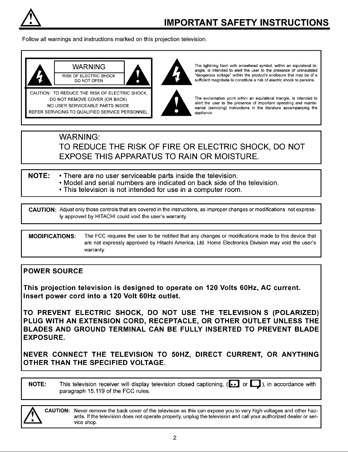
WARNING
RISK OF ELECTRIC SHOCK
DO NOT OPEN
CAUTION: TO REDUCE THE RISK OF ELECTRIC SHOCK,
DO NOT REMOVE COVER (OR BACK)
NO USER SERVICEABLE PARTS INSIDE
REFER SERVICING TO QUALIFIED SERVICE PERSONNEL
WARNING:
TO REDUCE THE RISK OF FIRE OR ELECTRIC SHOCK, DO NOT
I
NOTE: • There are no user serviceable parts inside the television.
I
CAUTION: Adjust only those controls that are covered in the instructions, as improper changes or modifications not express-
I
EXPOSE THIS APPARATUS TO RAIN OR MOISTURE.
• Model and serial numbers are indicated on back side of the television.
• This television is not intended for use in a computer room.
ly approved by HITACHI could void the user's warranty.
The lightning flash with arrowhead symbol, within an equilateral tri-
angle, is intended to alert the user to the presence of uninsulated
"dangerous voltage" within the product's enclosure that may be of a
sufficient magnitude to constitute a risk of electric shock to persons
The exclamation point within an equilateral triangle, is intended to
alert the user to the presence of important operating and mainte-
nance (servicing) instructions in the literature accompanying the
appliance
MODIFICATIONS: The FCC requires the user to be notified that any changes or modifications made to this device that
are not expressly approved by Hitachi America, Ltd. Home Electronics Division may void the user's
I
POWER SOURCE
This projection television is designed to operate on 120 Volts 60Hz, AC current.
Insert power cord into a 120 Volt 60Hz outlet.
TO PREVENT ELECTRIC SHOCK, DO NOT USE THE TELEVISION S (POLARIZED)
PLUG WITH AN EXTENSION CORD, RECEPTACLE, OR OTHER OUTLET UNLESS THE
BLADES AND GROUND TERMINAL CAN BE FULLY INSERTED TO PREVENT BLADE
EXPOSURE.
NEVER CONNECT THE TELEVISION TO 50HZ, DIRECT CURRENT, OR ANYTHING
)THER THAN THE SPECIFIED VOLTAGE.
This television receiver will display television closed captioning, (r_! or [_ ), in accordance with
I NOTE:
paragraph 15.119 of the FCC rules.
warranty.
,_ CAUTION: Never remove the back cover of the television as this can expose you to very high voltages and other haz-
ards. If the television does not operate properly, unplug the television and call your authorized dealer or ser-
vice shop.
2

IMPORTANT SAFETY INSTRUCTIONS
IMPORTANT SAFETY INSTRUCTIONS
CAUTION: • Read these instructions.
• Keep these instructions.
SAFETY POINTS YOU SHOULD KNOWABOUT
YOUR HITACHI PROJECTION TELEVISION
• Heed all warnings.
• Followall instructions
Our reputation has been built on the quality, performance, and ease of service of HiTACHi televisions.
Safety is also foremost in our minds in the design of these units. To help you operate these products properly, this section illustrates safety tips which
will be of benefit to you. Please read it carefully and apply the knowledge you obtain from it to the proper operation of your HITACHI television.
Please fill out your warranty card and mail it to HITACHI. This will enable HITACHI to notify you promptly in the improbable event that a safety
problem should be discovered in your product model.
FOR YOUR PERSONAL SAFETY
t DO not defeat the safety pug3ose of
the potadzed or grounding4ype plug
A polarized plug has two blades w_
one wider than the otheF A
grounding type plug has two blades
and a third grounding prong¸ The
wide blade or the third prong are
provided for your safety¸ If the
provided plug does not fit into your
outlet, consug an electrician for
replacement of the obsolefe Outlet¸
2 When the power cord or plug is
damaged or frayed, unpiug the
television from the wall outlet and
refer servicing to qualdied service
personnel¸
3 Do not overload wall outlets and
extension cords as this can result in
fire or ele_ic shock
4 Protect the power cord from being
walked on or pinched pardcularly at
plugs, convenience receptacles,
and the point where they exit from
the apparatus¸
5 DO not attempt to service the
television yourseff as opening or
removing covers may expose you
to dangerous voltage or other
hazards Refer all servicing to
qualified service personnel
6 Never pt_sh objects of any kind into unstable cart, stand, or table The
the television's cabinet stot$ as they television may fail, causing
may touch dangerous voltage points serious bodily injury, es pecialty to
or short out parts that could res_t in a child, _et Or adult, and serious
liquid of any kind on the television only with an approved cad Or
a fire or electric shock Never spill damage to the appliance Use
7 If the television has been dropped or manufacturer, or sold with the
the cabinet has been damaged, television¸ Wall or shelf mounting
unplug the television from the wall should follow the manufacturer's
ouget andreferservic, lngtoqualgled instructions, and should use a
8 Refer atl servicing to qualified ser-
vice personnel Servicing is 11-2 Use only with the cart, stand,
required when the apparatus has f_ipod, bracket, or table spedfied
been damaged in any way, such by the manufacturer, or sok_ wilh
service personnel mounting kit approved by the
as power-suppty cord or plug is the apparatues VV_qena cad is
damaged, liquid has been spitled used, use caution when moving
apparatus, the apparatus has avoid injury from tip-over
been exposed to rain ol moisture,
or objects have felten into the the cardappalatus combinafJon to
does not operate normally, or has
been dropped
9 DO not subject your television to
impact of any kind Be careful not to
damage the picture tube surface
Clean only w_th dry cloth
11-t DO not ptace the television on an
stand recommended by the
manufacturer
PROTECTION AND LOCATION OF YOUR TELEVISION
t2 DO not use Ibis apparatus near
water
• Never expose the television to
rain or water If the set has been
exposed to rain or wate_ unplug
television from wall outlet and
refer to qualified service person-
nel¸
t3 Choose a place where light
(artificial or sunlight) does not
shine directly on the screen¸
_4Ot t4 Avoid dusty places Accumulafed C'-_'_'*'_ "
feiiure of the television when Mgh
dust inside the chassis may cause
humidity persists
15 The television has slots or openings
in the cabinet for ventilation
purposes which provide reliable
operation of the receiver and
overheating¸ These openings must
not be blocked or covered
protect the felevision from _ •
• DO not block any ventilation open-
ings Instalt in accordance with the
manufacturer's instructions¸
• Never cover the slots or openings
with cloth or other material
3
Never block the bottom ventilation
slots of the television by placing it on
a bed, sofa, r,Jg, etc
DO not install near any heat sources ,,cP ,,\
such as radiators, heat registers, f#._ _j
stoves, or other apparatus (including #' ,="
ampi,fiers) that produce heat ,_[]
Never place the television near or
over a radiator or heat generater
Never place the television in a built-in _1_
enclosure unless proper ventilation
is provided
PROTECTION AND LOCATION OF YOUR TELEVISION
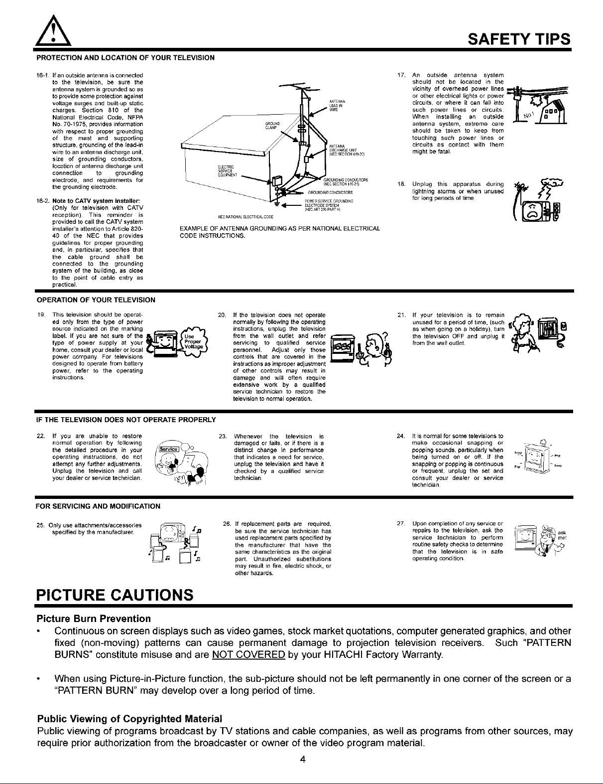
t6-t If an outside antenna isconnected
to the television, be sure the
antenna system is groundert so as
to prov_e some protection against
voltage surges and btliit-up static
charges¸ Section 810 of the
National Eiectecal Codel NFPA
NO 70_1975_ provides information
with respect to proper gretJnding
of the mast anrt supporting
structurel grounding Of the lead_in
wire to an antenna discharge uniL
size of grounding eonducto_,
location of antenna discharge unit
connection to grotlnding
electrode, and requiremen{s for
the grotJnding electrode¸
_6-2, Note to CATV system installer:
(Only for television with CATV
reception)¸ This reminrter is
provirtert to call the CATV system
insteksr's altention to Articte g20_
40 of the NEC that provides
guidelines for proper grounrting
and, in partictJlar, specifies that
the cable ground shall be
connected to the grounding
system of the building, as dose
to the point Of cable entrg as
practical
OPERATION OF YOUR TELEVISION
t9 This television shouEd be operat-
ed only from the type of power
source indicated on the marking
label¸ If you are not sure of the
type of power stJpply at your
home_ consu_ your rte_er or _oca_
power compar_y For _e_evisions
designed to operate from Pa_ery
power, refer _ the operating
in$1ruchon$_
20 If the television does not operate
normally by fctlowing the operating
instruchons, unptug the television
from the wail outlet and refer
servicing to qualified service
personnel Adjust only lhose
co_treL_ that are covered in the
instruct}ons as improper adjustment
of other controls m_y result in
damage and will often require
extensive work by a qu_lg_ed
$ewice technician to restore lhe
te_ev_sion to normal oper_lion
SAFETY TIPS
17
An outside antenna system
should not be Ioeatert in the
victnity of overhead power lines
or other electrical lights or power
eireuksl or where it can fall into
such power tines or circuits¸
When installing an outside
antenna systeml extreme care
shouirt be taken to keep from
touching such power lines Or
circuits as contact wire them
might be tetal
18
Unplug this apparatus during
lightning storms or when unused
for long periods of time
21 If your teEevision is to remain A .--_
untJsed for a periort of time, (such
as when going On a hctidsy), turn
the television OFF _nd unplt_g it
from lhe walt outlet
9
IF THE TELEVISION DOES NOT OPERATE PROPERLY
22 If you are unable to restore
normal operation by tollowing
the deteiied procedure in your
operating instructions, do not
altempt any further adjustments
Unplug the television and call
your dealer or service technician
23 Whenever the television is
rtamaged or teils, or _fthere is a
rtistinct change in pel_ormance
tha_ indicates a need for service,
unplug the television and have il
checked by a qualified service
technician¸
24 It is normal for some televisions to
make occasional snapping or ._.
popping sounrtsl partictJlaby when _ _
0elngtornodono,o0,,,.e ]:::
snapping or popping iscontinuous
or frequent, unplug the set anrt
consult your deater or service
technician
FOR SERVICING AND MODIFICATION
25 Onty use attachments/accessories
specified by the m_nufactorer
26 If replacement parts are reqctre_,
be sure the service technician has
used replacement parts specified by
the manutecturer that have the
same characteristics as the original
part Unauthorized substitutions
may resug in f_rel electdc shock, Or
other hazards¸
27
Upon completion of any service or
repairs to the television, ask the
service technician to perform
routine safety checks to determine
_hat the television is in safe
operating condition
PICTURE CAUTIONS
Picture Burn Prevention
Continuous on screen displays such as video games, stock market quotations, computer generated graphics, and other
fixed (non-moving) patterns can cause permanent damage to projection television receivers. Such "PATTERN
BURNS" constitute misuse and are NOT COVERED by your HITACHI Factory Warranty.
When using Picture-in-Picture function, the sub-picture should not be left permanently in one corner of the screen or a
"PATTERN BURN _may develop over a long period of time.
Public Viewing of Copyrighted Material
Public viewing of programs broadcast by TV stations and cable companies, as well as programs from other sources, may
require prior authorization from the broadcaster or owner of the video program material.
4
ACCESSORIES
Check to make sure you have the following accessories before disposing of the packing material.
PART NAME ILLUSTRATION
PART NO.
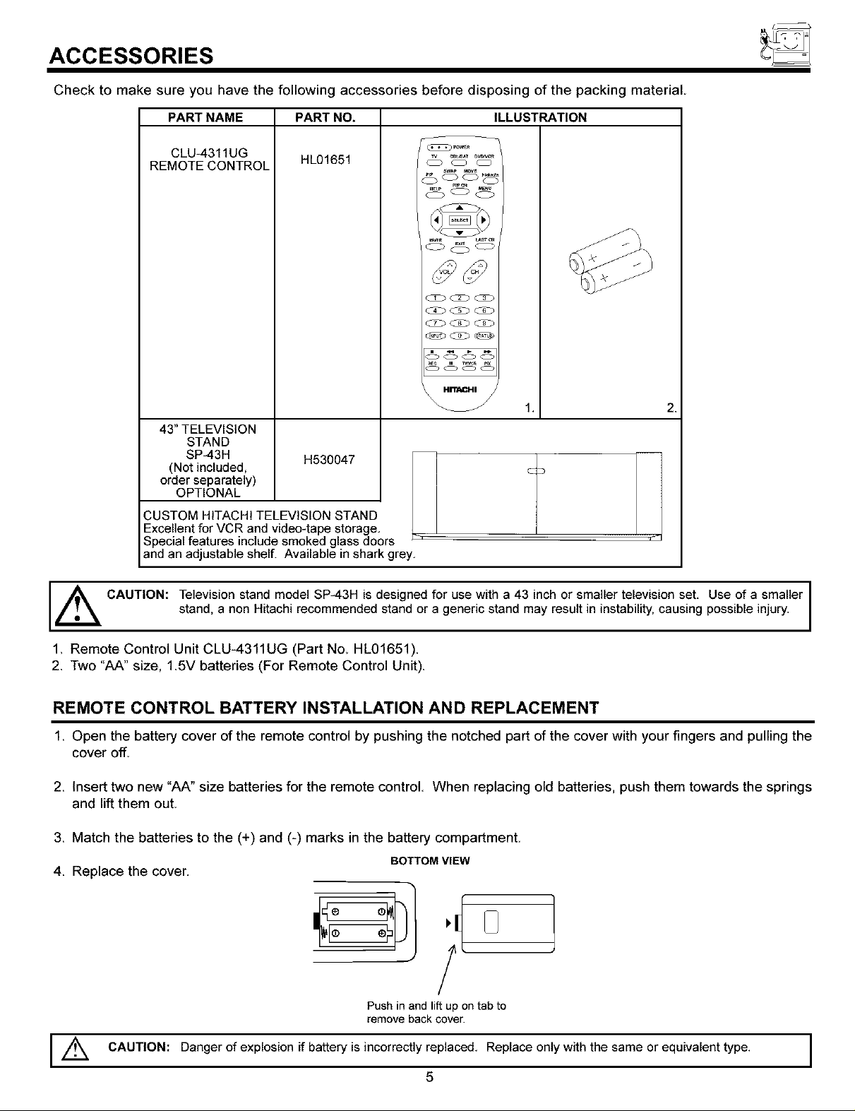
CLU-4311UG
REMOTE CONTROL
43" TELEVISION
STAND
SP-43H
(Not included,
order separately)
OPTIONAL
CUSTOM HITACHI TELEVISION STAND
Excellent for VCR and video-tape storage,
Special features include smoked glass doors
and an adjustable shelf. Available in shark grey.
HL01651
H530047
wA _o
O .... O
_ELp _U
OOO
i= Tw_
oo
2.
_, CAUTION: Television stand model SP-43H is designed for use with a 43 inch or smaller television set. Use of a smaller
stand, a non Htach recommended stand or a gener c stand may resut n nstab ty, caus ng possb e njury.
1. Remote Control Unit CLU-4311UG (Part No. HL01651).
2. Two "AA" size, 1.5V batteries (For Remote Control Unit).
REMOTE CONTROL BATTERY INSTALLATION AND REPLACEMENT
1 Open the battery cover of the remote control by pushing the notched part of the cover with your fingers and pulling the
cover off.
2 Insert two new "AA" size batteries for the remote control When replacing old batteries, push them towards the springs
and lift them out.
3 Match the batteries to the (+) and (-) marks in the battery compartment.
4 Replace the cover.
BOTTOM VIEW
F
J
Push in and lift up on tab to
remove back cover.
I,/_ CAUTION: Danger of explosion if battery is incorrectly replaced. Replace only with the same or equivalent type. I
5
I
I
HOW TO SET UP YOUR NEW HITACHI PROJECTION TV
ANTENNA
Unless your TV is connected to a cable TV system or to a centralized antenna system, a good outdoor color TV antenna is
recommended for best performance. However, if you are located in an exceptionally good signal area that is free from interference and
multiple image ghosts, an indoor antenna may be sufficient.
LOCATION
Select an area where sunlight or bright indoor illumination will not fall directly on the picture screen. Also, be sure that the location
selected allows a free flow of air to and from the perforated back cover of the set.
To avoid cabinet warping, cabinet color changes, and increased chance of set failure, do not place the TV where temperatures can
become excessively hot, for example, in direct sunlight or near a heating appliance, etc.
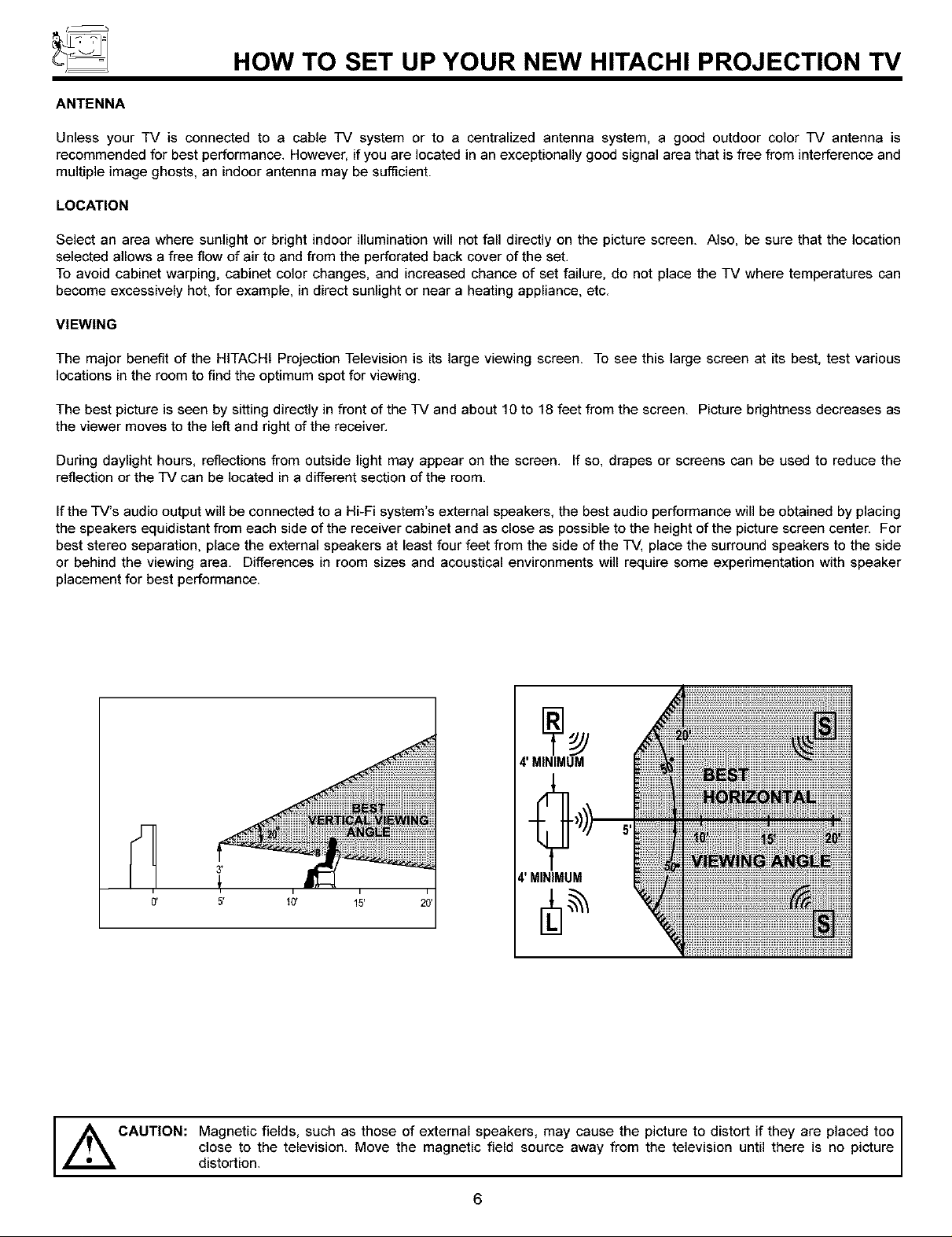
VIEWING
The major benefit of the HITACHI Projection Television is its large viewing screen. To see this large screen at its best, test various
locations in the room to find the optimum spot for viewing.
The best picture is seen by sitting directly in front of the TV and about 10 to 18 feet from the screen. Picture brightness decreases as
the viewer moves to the left and right of the receiver.
During daylight hours, reflections from outside light may appear on the screen. If so, drapes or screens can be used to reduce the
reflection or the TV can be located in a different section of the room.
Ifthe TV's audio output will be connected to a Hi-Fi system's external speakers, the best audio performance will be obtained by placing
the speakers equidistant from each side of the receiver cabinet and as close as possible to the height of the picture screen center. For
best stereo separation, place the external speakers at least four feet from the side of the TV, place the surround speakers to the side
or behind the viewing area. Differences in room sizes and acoustical environments will require some experimentation with speaker
placement for best performance.
4' MINIMUM
4' MINIMUM
CAUTION: Magnetic fields, such as those of external speakers, may cause the
,_ picture to distort if they are placed too
distortion.Cl°seto the television. Move the magnetic field source away from the te ev s on unt there s no p cture
6
HOOK-UP CABLES AND CONNECTORS
Most video/audio connections between components can be made with shielded video and audio cables that have phono connectors.
For best performance, video cables should use 75-Ohm coaxial shielded wire. Cables can be purchased from most stores that sell
audio/video products. Below are illustrations and names of common connectors. Before purchasing any cables, be sure of the output
and input connector types required by the various components and the length of each cable.
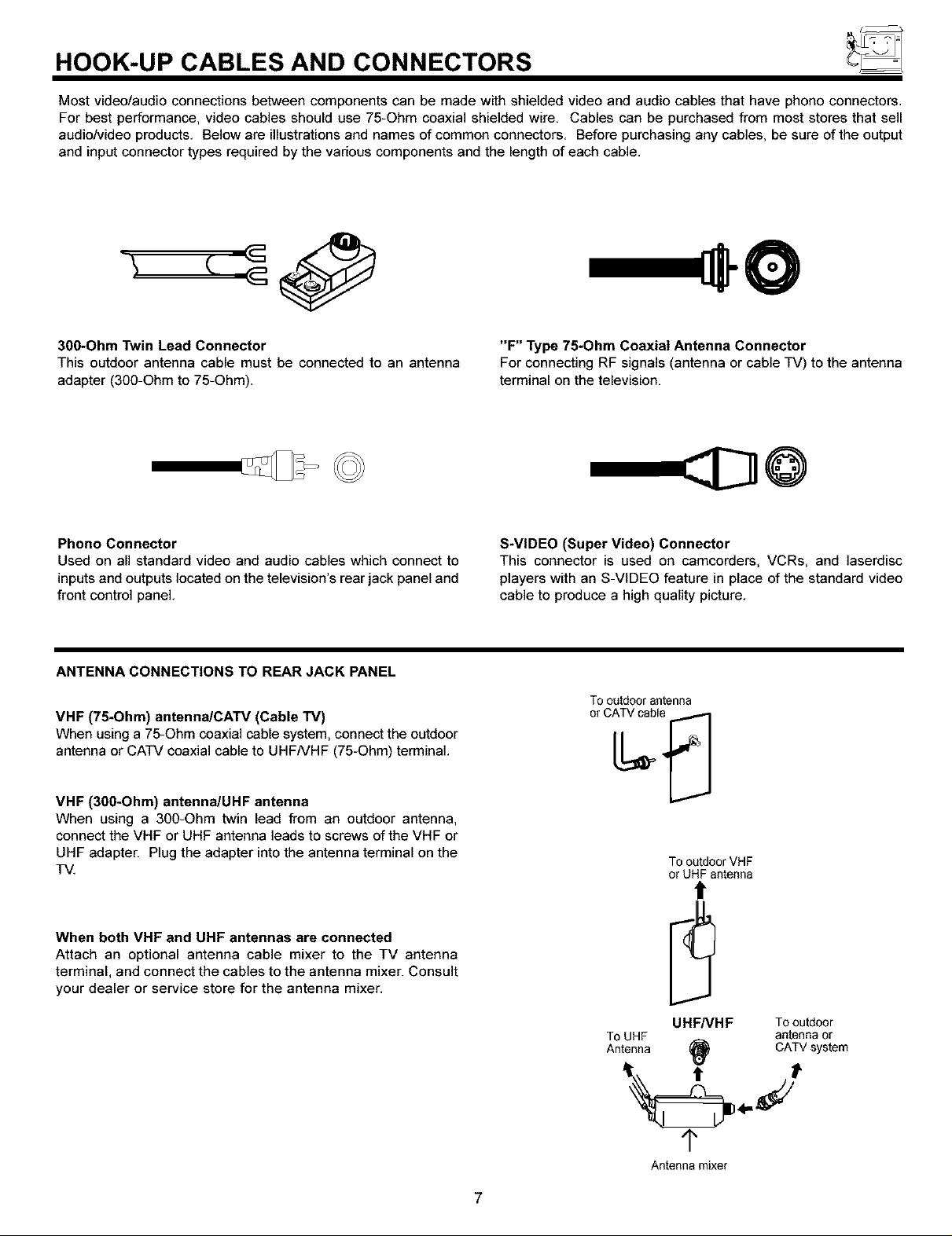
30g-Ohm Twin Lead Connector
This outdoor antenna cable must be connected to an antenna
adapter (300-Ohm to 75-Ohm).
Phono Connector
Used on all standard video and audio cables which connect to
inputs and outputs located on the television's rear jack panel and
front control panel.
ANTENNA CONNECTIONS TO REAR JACK PANEL
VHF (75-Ohm) antenna/CATV (Cable TV)
When using a 75-Ohm coaxial cable system, connect the outdoor
antenna or CATV coaxial cable to UHFNHF (75-Ohm) terminal.
"F" Type 75-Ohm Coaxial Antenna Connector
For connecting RF signals (antenna or cable TV) to the antenna
terminal on the television.
S-VIDEO (Super Video) Connector
This connector is used on camcorders, VCRs, and laserdisc
players with an S-ViDEO feature in place of the standard video
cable to produce a high quality picture.
Tooatdoorantenna
VHF (30O*Ohm) antenna/UHF antenna
When using a 300-Ohm twin lead from an outdoor antenna,
connect the VHF or UHF antenna leads to screws of the VHF or
UHF adapter. Plug the adapter into the antenna terminal on the
TV.
When both VHF and UHF antennas are connected
Attach an optional antenna cable mixer to the TV antenna
terminal, and connect the cables to the antenna mixer. Consult
your dealer or service store for the antenna mixer.
To outdoor VHF
or UHF antenna
t
UHFNHF Tooutdoor
ToUHF antennaor
Antenna (_ CATVsystem
¢
Antenna mixer
7
43GX10B/50GX30B
Ir
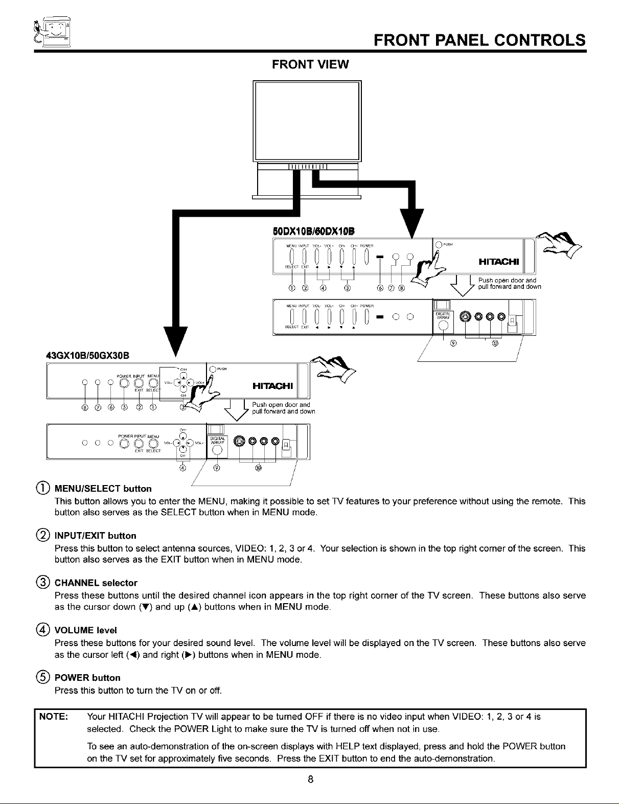
FRONT PANEL CONTROLS
FRONT VIEW
IliIIlillI
SODX10B/60DX10! _lr
..........ooi T-oo
S_LEOTEXIT _ • • •
HITACHI
Push open doorand
7 pull forward and down
III
Push open door and
7 pull forward and down
o o o0000 .......
MENU/SELECT button /
This button allows you to enter the MENU, making it possible to set TV features to your preference without using the remote. This
button also serves as the SELECT button when in MENU mode.
(_) INPUT/EXIT button
Press this button to select antenna sources, VIDEO: 1, 2, 3 or 4. Your selection is shown in the top right corner of the screen. This
button also serves as the EXIT button when in MENU mode.
(_) CHANNEL selector
Press these buttons until the desired channel icon appears in the top right corner of the TV screen. These buttons also serve
as the cursor down (_') and up (A) buttons when in MENU mode.
(_ VOLUME level
Press these buttons for your desired sound level. The volume level will be displayed on the TV screen. These buttons also serve
as the cursor left (4) and right (1_) buttons when in MENU mode.
(_ POWER button
Press this button to turn the TV on or off.
NOTE:
Your HITACHI Projection TV will appear to be turned OFF if there is no video input when VIDEO: 1, 2, 3 or 4 is
selected. Check the POWER Light to make sure the TV is turned off when not in use.
To see an auto-demonstration of the on-screen displays with HELP text displayed, press and hold the POWER button
on the TV set for approximately five seconds. Press the EXIT button to end the auto-demonstration.
8
I
FRONT PANEL CONTROLS
(_) POWER light
YOUwill see a red light when the TV is turned on.
(_ PERFECT PICTURE sensor
The PERFECT PICTURE sensor will make automatic picture adjustments depending on the amount of light in the room to give the
best picture. (see page 48)
(_) REMOTE CONTROL sensor
Point your remote at this area when selecting channels, adjusting volume, etc.
(_ DIGITAL ARRAY
Use this button to enter DIGITALARRAY mode. This will allow you to adjust your picture quality to optimum performance.
(see page 38)
(_) FRONT INPUT JACKS (for VIDEO: 3)
Use these audio/video jacks for a quick hook-up from a camcorder or VCR to instantly view your favorite show or new recording.
Press the INPUT button until VIDEO: 3 appears in the top right corner of the TV screen. If you have mono sound, insert the audio
cable into the left audio jack.
9
REAR SPEAKER
O _ONLV
V_F JHF
DJ
S-ViDEO S-V_DEO
!?
v
®
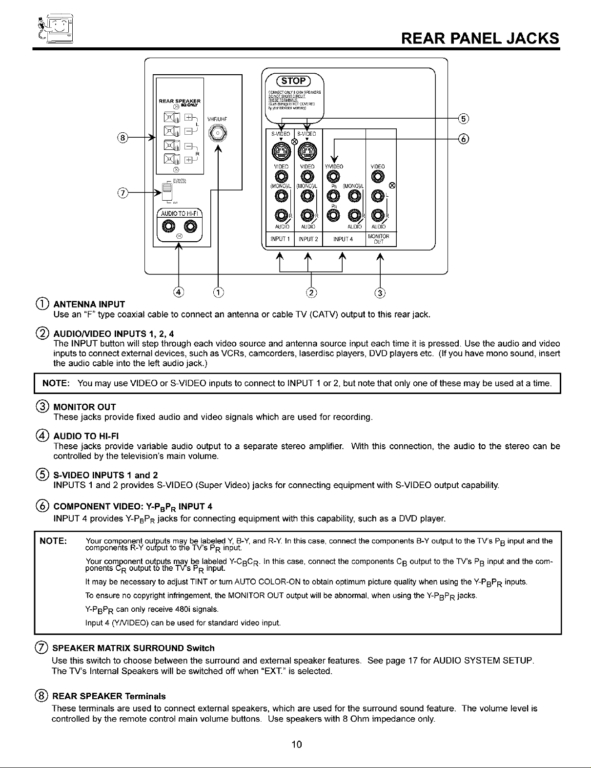
(_ ANTENNA INPUT
Use an "F" type coaxial cable to connect an antenna or cable TV (CATV) output to this rear jack.
VIDEO VIDEO YNIDEO VIDEO
@@@ @
(MONOyL {MONOI/L Pa (MONOyL
01 01 01
AUDIO AUDIO AUDIO AUDIO
INPUT 1 INPUT 2 INPUT 4 MONITOR
OUT
REAR PANEL JACKS
®
®
(_ AUDIONIDEO INPUTS 1, 2, 4
The INPUT button will step through each video source and antenna source input each time it is pressed. Use the audio and video
inputsto connect external devices, such as VCRs, camcorders, laserdisc players, DVD players etc. (If you have mono sound, insert
the audio cable into the left audio jack.)
I NOTE: You may use VIDEO or S-VIDEO inputs to connect to INPUT 1 or 2, but note that only one of these may be used at a time. I
(_) MONITOR OUT
These jacks provide fixed audio and video signals which are used for recording.
(_ AUDIO TO HI-FI
These jacks provide variable audio output to a separate stereo amplifier, With this connection, the audio to the stereo can be
controlled by the television's main volume,
(_ S-VIDEO INPUTS 1 and 2
INPUTS 1 and 2 provides S-VIDEO (Super Video) jacks for connecting equipment with S-VIDEO output capability.
(_) COMPONENT VIDEO: Y*PBPR INPUT 4
INPUT 4 provides Y-PBPR jacks for connecting equipment with this capability, such as a DVD player.
NOTE:
Your component outputs may be labeled Y, B-Y, and R-Y. In this case, connect the components B-Y output to the TV's PB input and the
components R-Y output to the TV's PR input.
Your component outputs may be labeled Y-CBC R. In this case, connect the components CB output to the TV's PB input and the com-
ponents L,R output to the TV's PR input.
It may be necessary to adjust TINT or turn AUTO COLOR-ON to obtain optimum picture quality when using the Y-PBPR inputs.
To ensure no copyright infringement, the MONITOR OUT output will be abnormal, when using the Y-PBPR jacks.
Y-PBPR can only receive 480i signals.
Input 4 (YNIDEO) can be used for standard video input.
(_ SPEAKER MATRIX SURROUND Switch
Use this switch to choose between the surround and external speaker features. See page 17 for AUDIO SYSTEM SETUP.
The TV's Internal Speakers will be switched off when "EXT." is selected.
(_) REAR SPEAKER Terminals
These terminals are used to connect external speakers, which are used for the surround sound feature. The volume level is
controlled bythe remote control main volume buttons. Use speakers with 8 Ohm impedance only.
10

REAR PANEL CONNECTIONS
_ Outsideantennaor
cableTVcoaxialcable
CableTV Box
See tips on _]
AL_310 AUDIO I AUZ310
Nf>d _ IN_5 2 _f>dT 4 _nOR
R Y PB PR
[? ++++
OUTPUT
DVDPlayer,
Laserdisc player,etc.
OUt
INPUT V L
@
Stereo System Amplifier
onpage12
)@©@
[_. V L ROUTPUT
VCR#2
Typical full feature setup. Follow connections that pertain to your personal entertainment system.
11
REAR SPEAKER TERMINAL CONNECTIONS
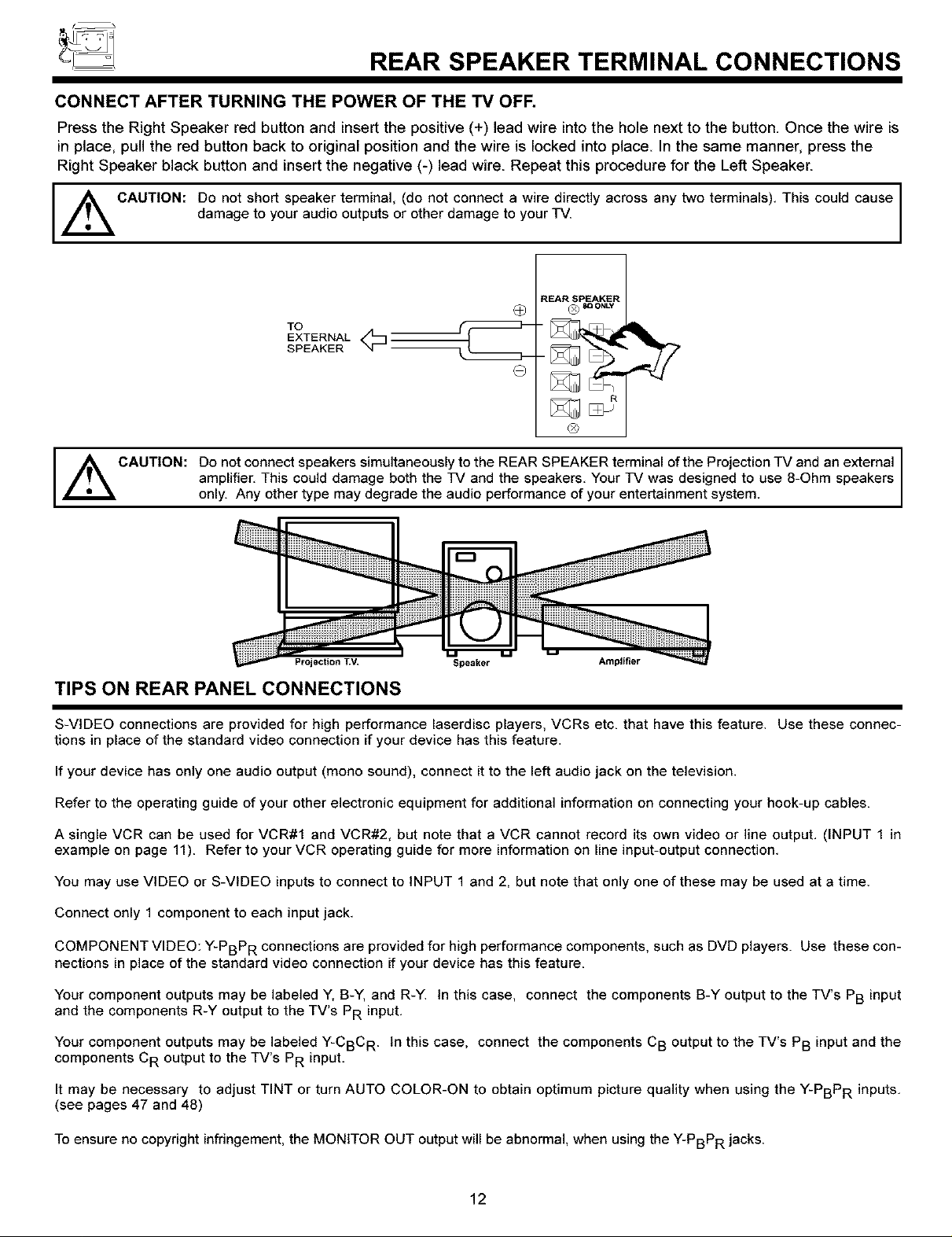
CONNECT AFTER TURNING THE POWER OF THE TV OFF.
Press the Right Speaker red button and insert the positive (+) lead wire intothe hole next to the button. Once the wire is
in place, pull the red button back to original position and the wire is locked into place. In the same manner, press the
Right Speaker black button and insert the negative (-) lead wire. Repeat this procedure for the Left Speaker.
_ CAUTION: Do not short speaker terminal, (do not connect a wire directly across any two terminals). This could cause
damage to your audio outputs or other damage to your TV.
REAR SPEAKER
O ® _ o.Lv
TO
EXTERNAL
SPEAKER
Q
®
Do not connect speakers simultaneously to the REAR SPEAKER terminal of the Projection TV and an external
,_CAUTION:
amplifier. This could damage both the TV and the speakers. Your TV was designed to use 8-Ohm speakers
only. Any other type may degrade the audio performance of your entertainment system.
Projection T_/. Speaker Amplifier
TIPS ON REAR PANEL CONNECTIONS
S-VIDEO connections are provided for high performance laserdisc players, VCRs etc. that have this feature. Use these connec-
tions in place of the standard video connection if your device has this feature.
If your device has only one audio output (mono sound), connect it to the left audio jack on the television.
Refer to the operating guide of your other electronic equipment for additional information on connecting your hook-up cables.
A single VCR can be used for VCR#1 and VCR#2, but note that a VCR cannot record its own video or line output. (INPUT 1 in
example on page 11). Refer to your VCR operating guide for more information on line input-output connection.
You may use VIDEO or S-VIDEO inputs to connect to INPUT 1 and 2, but note that only one of these may be used at a time.
Connect only 1 component to each input jack.
COMPONENT VIDEO: Y-PBPR connections are provided for high performance components, such as DVD players. Use these con-
nections in place of the standard video connection if your device has this feature.
Your component outputs may be labeled Y, B-Y, and R-Y. In this case, connect the components B-Y output to the TV's PB input
and the components R-Y output to the TV's PR input.
Your component outputs may be labeled Y-CBC R. In this case, connect the components CB output to the TV's PB input and the
components CR output to the TV's PR input.
It may be necessary to adjust TINT or turn AUTO COLOR-ON to obtain optimum picture quality when using the Y-PBPR inputs.
(see pages 47 and 48)
To ensure no copyright infringement, the MONITOR OUT output will be abnormal, when using the Y-PBPR jacks.
12
EXTERNAL CONNECTIONS
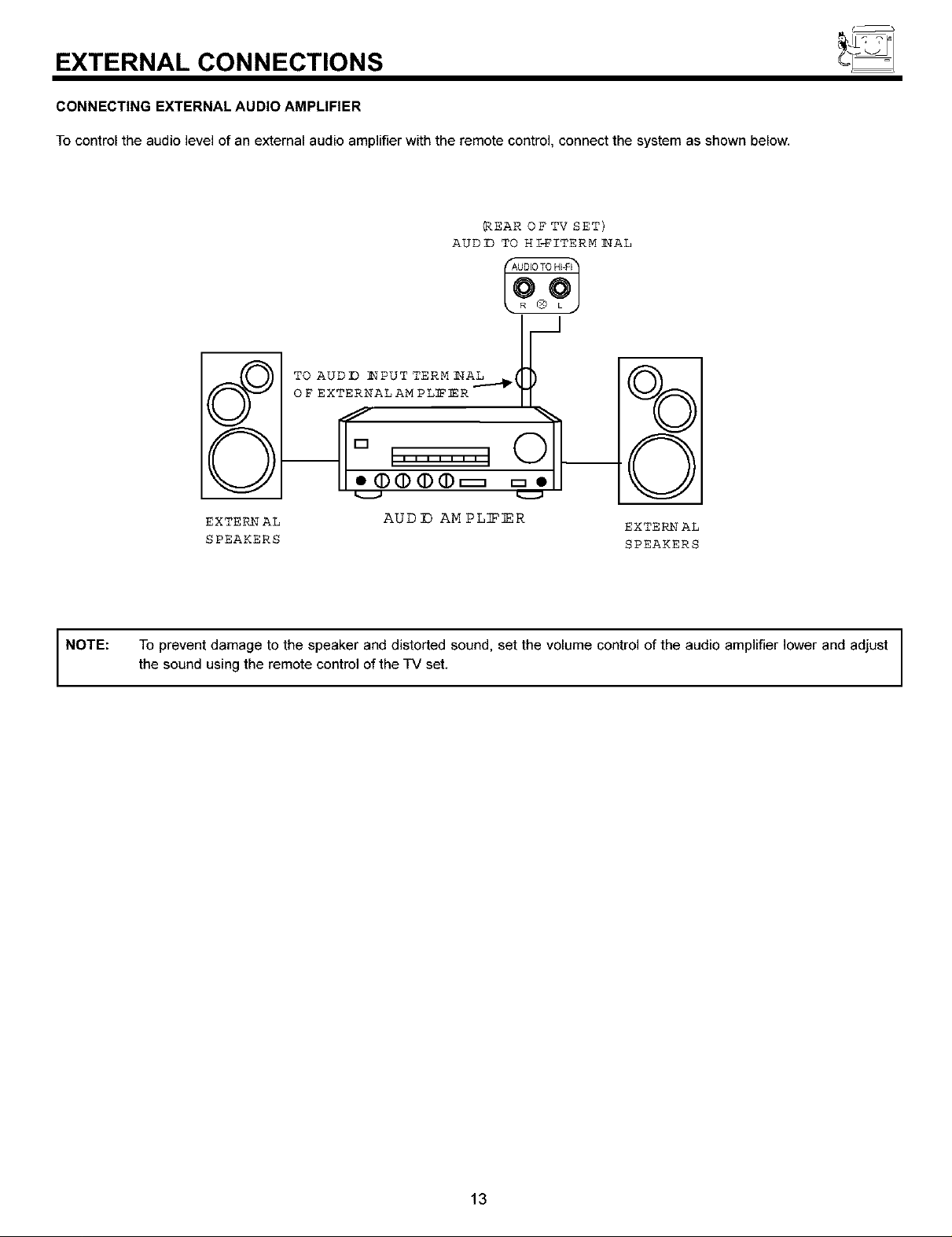
CONNECTING EXTERNAL AUDIO AMPLIFIER
To control the audio level of an external audio amplifier with the remote control, connect the system as shown below.
_EAR OF TV SET)
AUDD TO HI_ITERM _AL
o_o_x_ZZ_-_
%
O
NOTE:
EXTERNAL AUD ]D AM PL]FER
SPEAKERS SPEAKERS
To prevent damage to the speaker and distorted sound, set the volume control of the audio amplifier lower and adjust
the sound using the remote control of the TV set.
EXTERNAL
13
CONNECTING EXTERNAL VIDEO SOURCES
The exact arrangement you use to connect the VCR, camcorder, laserdisc player, and DVD player to your TV set is dependent on the
model and features of each component. Check the owner's manual of each component for the location of video and audio inputs and
outputs.
The following connection diagrams are offered as suggestions. However, you may need to modify them to accommodate your particular
assortment of components and features. For best performance, video and audio cables should be made from coaxial shielded wire.
Before Operating External Video Source
The input mode is changed every time the INPUT button is pressed as shown below. Connect an external source to the INPUT terminal,
then press the INPUT button as necessary to view the input source. (see page 21)
INPUT MODE SELECTION ORDER
(ANTENNA) (INPUT)
12 > VIDEO
NOTE:
When the TV is set to VIDEO and a video signal is not received from the VIDEO INPUT jack on the jack panel of the TV
(Le., VCR/laserdisc player, etc. is not connected or the video device is OFF), the set will appear to be OFF.
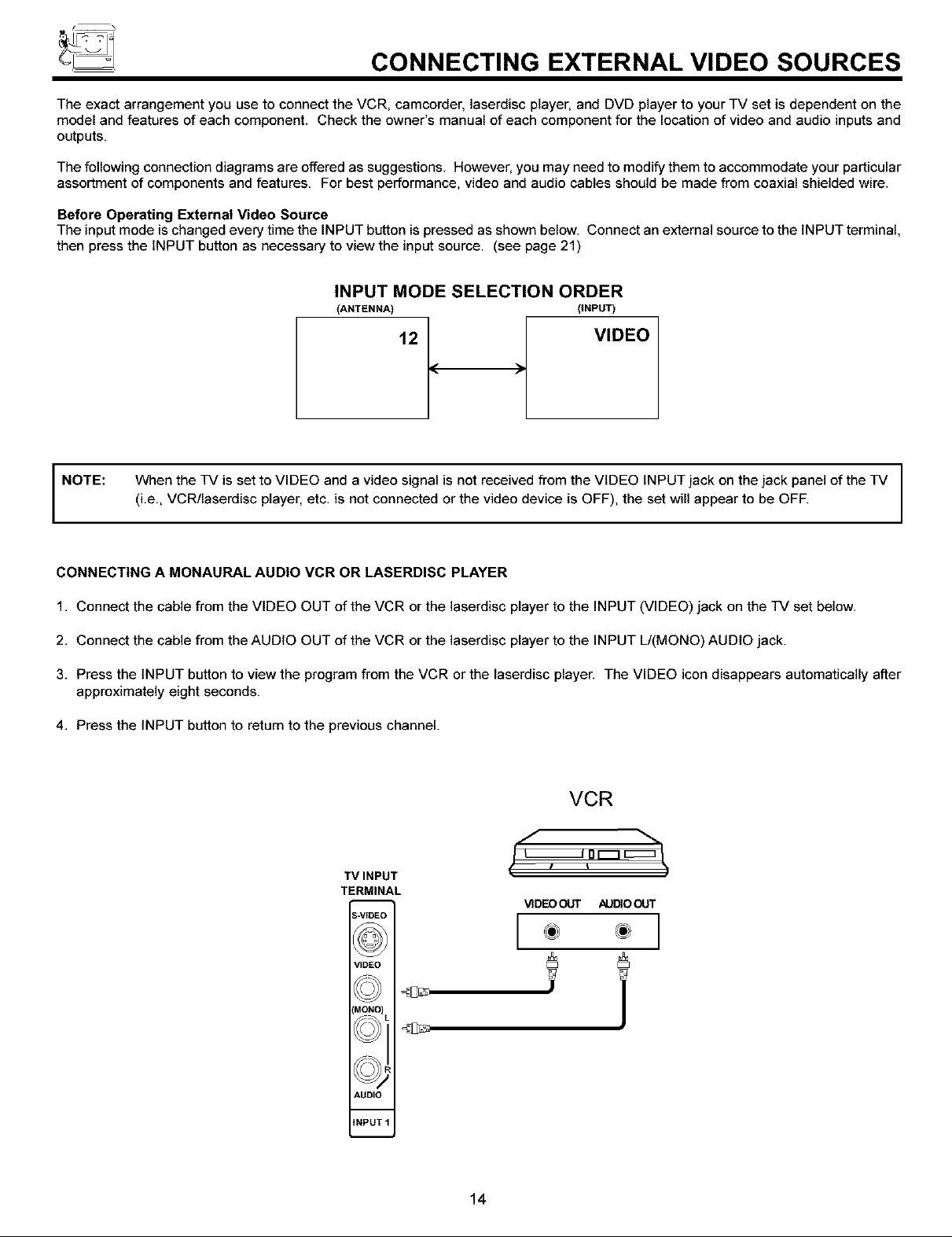
CONNECTING A MONAURAL AUDIO VCR OR LASERDISC PLAYER
1, Connect the cable from the VIDEO OUT of the VCR or the laserdisc player to the INPUT (VIDEO) jack on the TV set below,
2, Connect the cable from the AUDIO OUT of the VCR or the laserdisc player to the INPUT L/(MONO) AUDIO jack.
3, Press the INPUT button to view the program from the VCR or the laserdisc player, The VIDEO icon disappears automatically after
approximately eight seconds.
4, Press the INPUT button to return to the previous channel.
VCR
f
TVINPUT
TERMINAL
Z-VIDEO
VIDEOOOT /_UDIOOUT
VIDEO
MONO I
I(f )I_R
_J2
AUDIO
INPUT 1
!
14
CONNECTING EXTERNAL VIDEO SOURCES
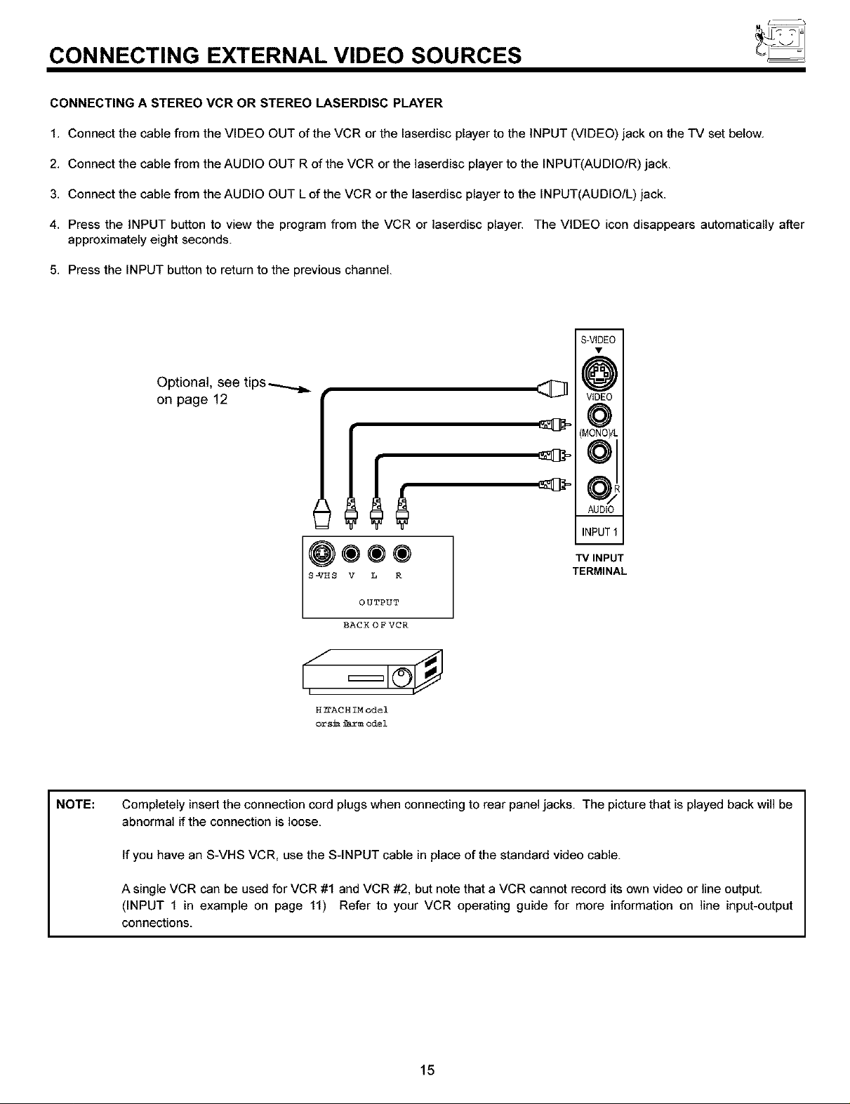
CONNECTING A STEREO VCR OR STEREO LASERDISC PLAYER
1. Connect the cable from the VIDEO OUT of the VCR or the laserdisc player to the INPUT (VIDEO) jack on the TV set below.
2. Connect the cable from the AUDIO OUT R of the VCR or the laserdisc player to the INPUT(AUDIO/R) jack.
3. Connect the cable from the AUDIO OUT L of the VCR or the laserdisc player to the INPUT(AUDIO/L) jack.
4. Press the INPUT button to view the program from the VCR or laserdisc player. The VIDEO icon disappears automatically after
approximately eight seconds.
5. Press the INPUT button to return to the previous channel.
m
S-VIDEO
Optional, see tips_
on page 12
S-VHS V L R
OUTPUT
BACK OFVCR
H IFACH IN odel
orsic farm odel
VIDEO
(MONO)/t
OJ
AUDIO
INPUT"
"IVINPUT
TERMINAL
NOTE:
Completely insert the connection cord plugs when connecting to rear panel jacks. The picture that is played back will be
abnormal if the connection is loose.
If you have an S-VHS VCR, use the S-INPUT cable in place of the standard video cable.
A single VCR can be used for VCR #1 and VCR #2, but note that a VCR cannot record its own video or line output,
(INPUT 1 in example on page 11) Refer to your VCR operating guide for more information on line input-output
connections.
15
CONNECTING EXTERNAL VIDEO SOURCES
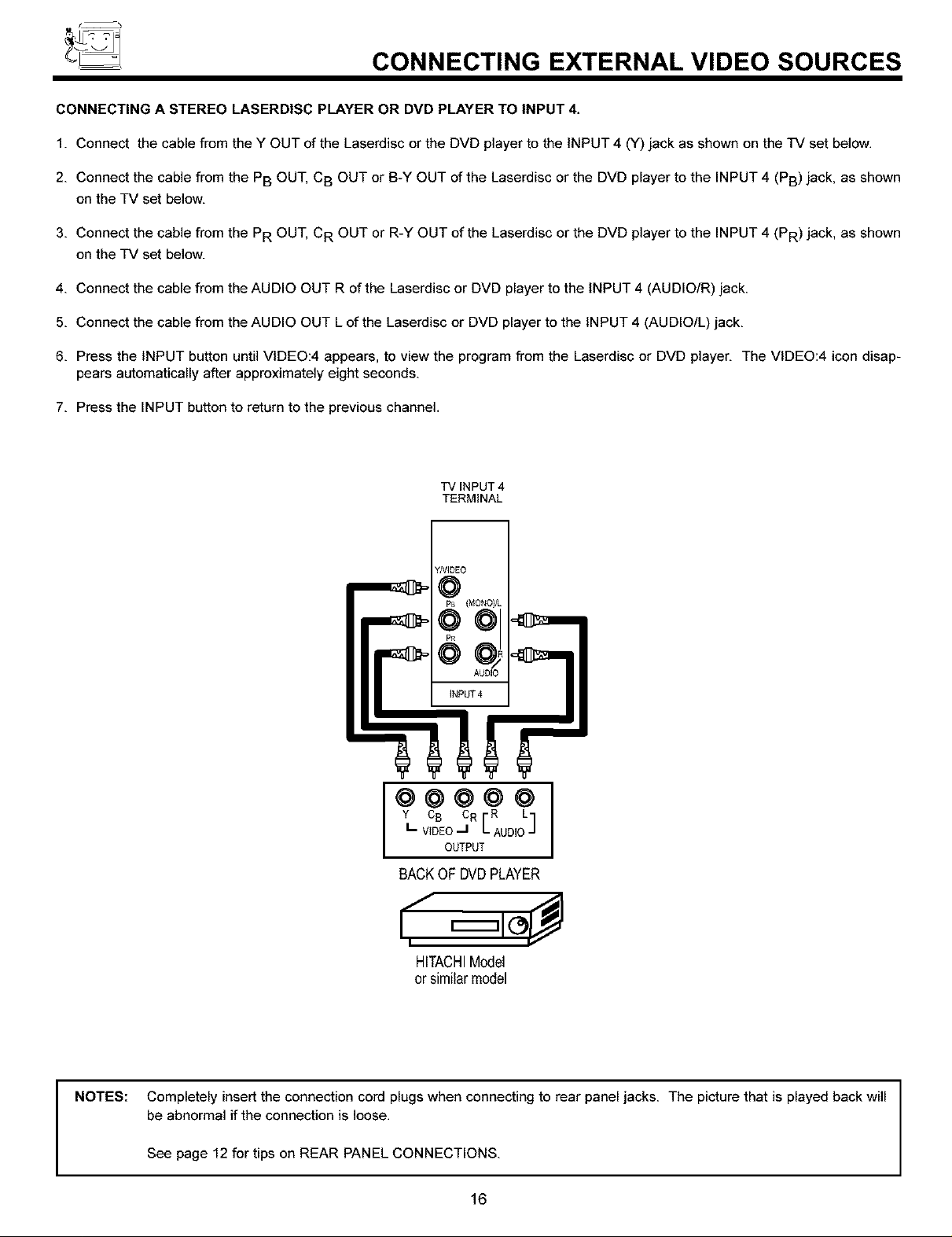
CONNECTING A STEREO LASERDISC PLAYER OR DVD PLAYER TO INPUT 4.
1. Connect the cable from the Y OUT of the Laserdisc or the DVD player to the INPUT 4 (Y) jack as shown on the TV set below.
2. Connect the cable from the PB OUT, CB OUT or B-Y OUT of the Laserdisc or the DVD player to the INPUT 4 (PB) jack, as shown
on the TV set below.
3. Connect the cable from the PR OUT, CR OUT or R-Y OUT of the Laserdisc or the DVD player to the INPUT 4 (PR) jack, as shown
on the TV set below.
4. Connect the cable from the AUDIO OUT R of the Laserdisc or DVD player to the INPUT 4 (AUDIO/R) jack.
5. Connect the cable from the AUDIO OUT L of the Laserdisc or DVD player to the INPUT 4 (AUDIO/L) jack.
6. Press the INPUT button until VIDEO:4 appears, to view the program from the Laserdisc or DVD player. The VIDEO:4 icon disap-
pears automatically after approximately eight seconds.
7. Press the INPUT button to return to the previous channel.
TV INPUT 4
TERMINAL
YMDEO
@
PB (MONO)/L
Y C8 CR R L
"V,DEO"[AUDIO]
@@@@@1
OUTPUT
BACKOF DVDPLAYER
,¢"
HITACHIModel
or similar model
NOTES: Completely insert the connection cord plugs when connecting to rear panel jacks. The picture that is played back will
be abnormal if the connection is loose.
See page 12 for tips on REAR PANEL CONNECTIONS.
16
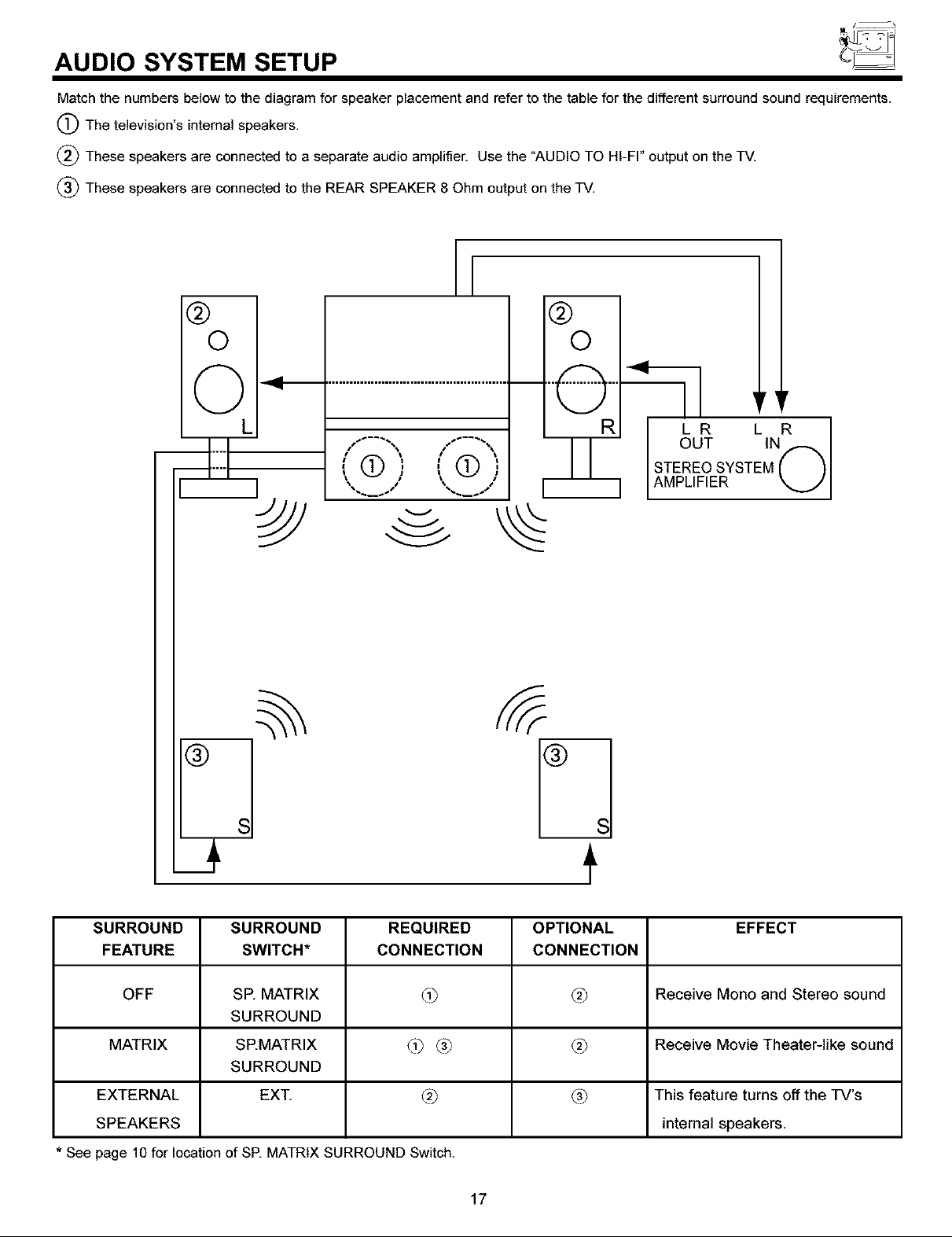
AUDIO SYSTEM SETUP
Match the numbers below to the diagram for speaker placement and refer to the table for the different surround sound requirements.
(_The television's internal speakers.
(_) These speakers are connected to a separate audio amplifier. Use the "AUDIO TO HI-FI" output on the TV.
_ These speakers are connected to the REAR SPEAKER 8 Ohm output on the TV.
[
@
©
Q _ ....................................................... Q'"
- ( '_ ( •
,,(9, ,,(9,
@
©
LR L R I
OUT IN I
STEREOSYSTEM( _1
AMPLIFIER "x....J I
®
SURROUND
FEATURE
OFF
MATRIX
EXTERNAL
SPEAKERS
* See page 10 for location of SP. MATRIX SURROUND Switch.
SURROUND
SWITCH*
SE MATRIX
SURROUND
SEMATRIX
SURROUND
EXT
REQUIRED
CONNECTION
@
@(31
®
17
s
t
OPTIONAL
CONNECTION
@
@
(31
EFFECT
Receive Mono and Stereo sound
Receive Movie Theater-like sound
This feature turns off the TV's
internal speakers.
THE REMOTE CONTROL
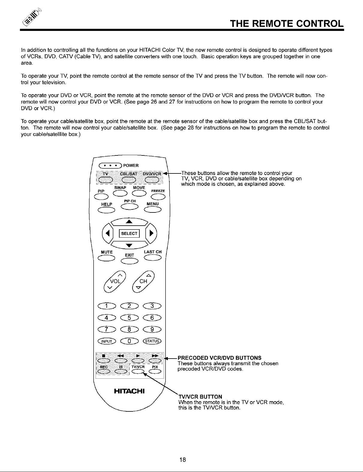
In addition to controlling all the functions on your HITACHI Color TV, the new remote control is designed to operate different types
of VCRs, DVD, CATV (Cable TV), and satellite converters with one touch. Basic operation keys are grouped together in one
area.
To operate your TV, point the remote control at the remote sensor of the TV and press the TV button. The remote will now con-
trol your television.
To operate your DVD or VCR, point the remote at the remote sensor of the DVD or VCR and press the DVDNCR button. The
remote will now control your DVD or VCR. (See page 26 and 27 for instructions on how to program the remote to control your
DVD or VCR.)
To operate your cable/satellite box, point the remote at the remote sensor of the cable/satellite box and press the CBUSAT but-
ton. The remote will now control your cable/satellite box. (See page 28 for instructions on how to program the remote to control
your cable/satelllite box.)
POWER
--These buttons allow the remote to control your
TV, VCR, DVD or cable/satellite box depending on
SWAP MOVE
which mode is chosen, as explained above.
HELP MENU
PIP CH
O0(ZD
MUTE LAST CH
EXIT
<:Z>
TVIVCR PIX
PRECODED VCR/DVD BUTTONS
These buttons always transmit the chosen
precoded VCR/DVD codes,
HITACHI
TVNCR BUTTON
When the remote is in the TV or VCR mode,
this is the TVNCR button.
18
 Loading...