

Hitachi 55FX20B, 50FX19K, 50FX18B Owner’s Manual
PROJECTION COLOR TV
OPERATING GUIDE
I I II I II II
IMPORTANT SAFEGUARDS
FIRST TIME USE
i ,'i' _ ,,, '_r,,_i.i,_ T, ,li,, 'irr_ ='
THE GENIUS REMOTE CONTROL
_-_ _ _ ON SCREEN DISPLAY
USEFUL INFORMATION INDEX
2-5
I
6-13
14-24
25-51
52-59
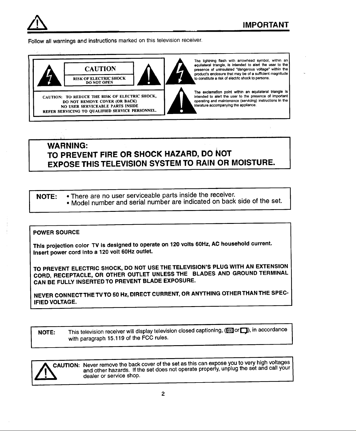
Follow all warnings and instructions marked on this television receiver.
IMPORTANT
i
_k CAUTION [
CAUTION: TO REDUCE THE RISK OF ELECTRIC SHOCK,
REFER SERVICING TO QUALIFIED SERVICE PERSONNEL.
RISK OF ELECTRIC SHOCK
DO NOT OPEN
DO NOT REMOVE COVER (OR BACK)
NO USER SERVICEABLE PARTS INSIDE
WARNING:
TO PREVENT FIRE OR SHOCK HAZARD, DO NOT
EXPOSE THIS TELEVISION SYSTEM TO RAIN OR MOISTURE.
• Model number and serial number are indicated on back side of the set.
I NOTE:
• There are no user serviceable parts inside the receiver. I
I A The lightning flash with arrowhead symbol, within an
• _, equilateral triangle, is intended to aled the user to the
_lrJIl_ presence of urdnsulated "dangerous voltage" within the
_, product's enclosure that may be of a sufficient magnitude
,_d_o constitute a risk of electdc shock to persons,
,&
• • intended to alert the user to the presence of important
J I operating and maintenance (servicing) instructions in the
I /_k The exclamation point within an equilateral tdangle Is
,__erature accompanying the appliance.
i
POWER SOURCE
This projection color TV is designed to operate on 120 volts 60Hz, AC household current.
Insert power cord into a 120 volt 60Hz outlet.
TO PREVENT ELECTRIC SHOCK, DO NOT USE THE TELEVISION'S PLUG WITH AN EXTENSION
CORD, RECEPTACLE, OR OTHER OUTLET UNLESS THE BLADES AND GROUND TERMINAL
CAN BE FULLY INSERTED TO PREVENT BLADE EXPOSURE.
NEVER CONNECTTHETVTO 50 Hz, DIRECT CURRENT, OR ANYTHING OTHERTHAN THE SPEC-
IFIED VOLTAGE.
This television receiver willdisplay television closed captioning,(r_or_), inaccordance I
I NOTE:
with paragraph 15.119 of the FCC rules.
and other hazards. If the set doesnotoperate properly,unplugthe set andcall your
AUTION: Never removethe backcoverof theset as thiscan expose youto very highvoltages
dealer or service shop.
2
I
I
SAFETY TIPS
IMPORTANT SAFEGUARDS
CAUTION:
* Read all of these instructions.
* Save these instructionsfor later use.
* Follow all warnings and instructionsmarked
on the televisionreceiver.
Our reputation has been built on the quality, performance, and ease of service of HITACHI television receivers.
Safety is also foremost in our minds in the design of these units. To help you operate these products properly, this section illustrates safety tips which will be of
benefit to you. Please read it carefully and apply the knowledge you obtain from it to the proper operation of your HITACHI television receiver.
Please fill out your warranty card at once and mail it to HITACHI. This will enable HITACHI to notify you promptly in the improbable event that a safety problem
should be discovered in your model of product.
SAFETY POINTS YOU SHOULD KNOW ABOUT
YOUR HITACHI TELEVISION RECEIVER
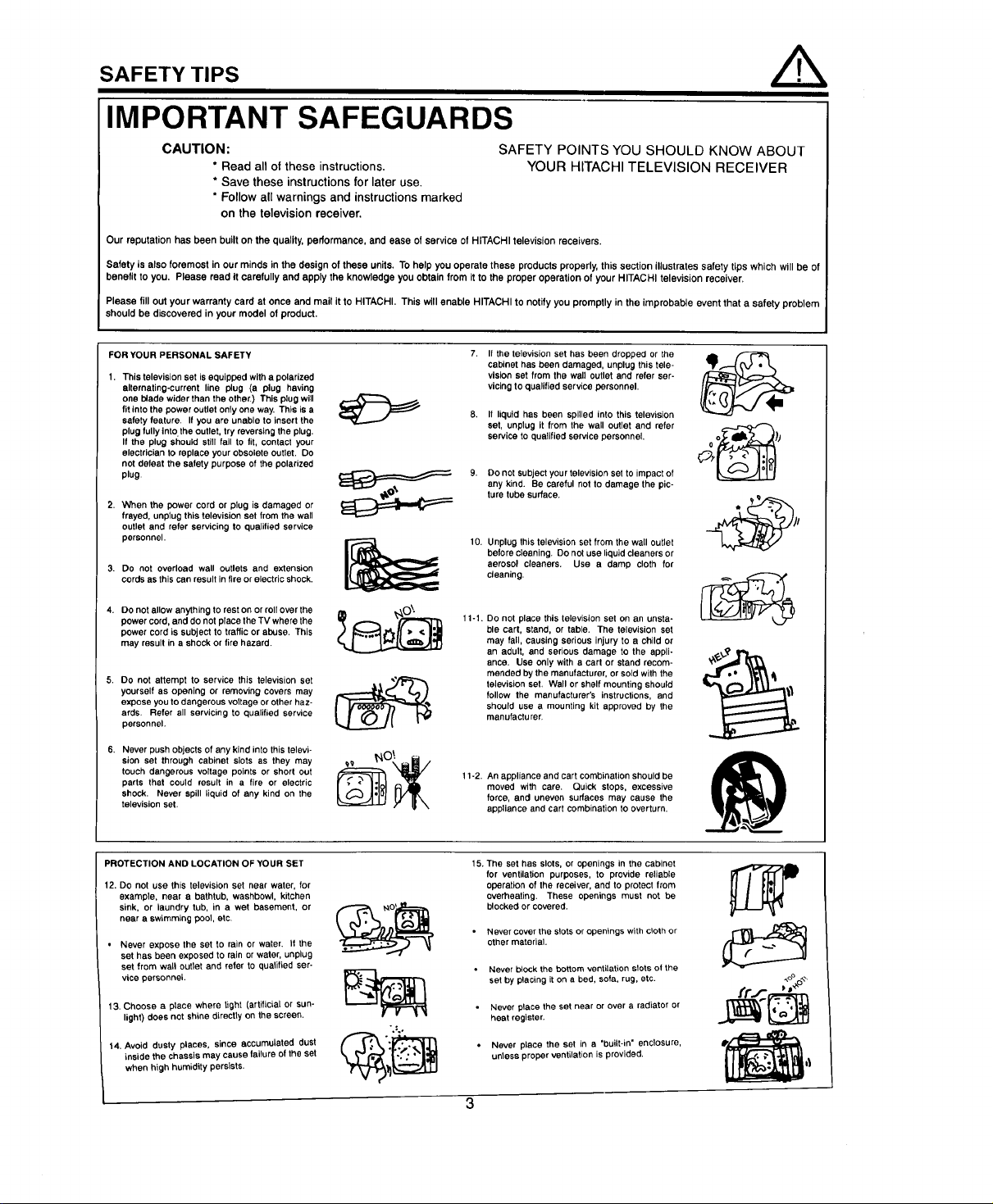
FOR YOUR PERSONAL SAFETY
1. This television set isequipped with a polarized
alternating-current line plug (a plug having
one blade wider than the other.) This plug will
fit into the power outletonly one way. This is a
safety feature. If you are unable to insert the
plug fullyinto the outlet, try reversing the plug.
If the plug should still fail to fit, contact your
electrician to replace your obsolete outlet. Do
not defeat the safety purpose of the polarized
plug.
2. When the power cord or plug is damaged or
frayed, unplug this television set from the wall
outlet and refer servicing to qualified service
personnel.
3. Do not overload wall outlets and extension
cords as this can result infireorelectric shock.
4. DOnot allow anything to rest on or roll over the
power cord, and do not place the TV where the
power cord is subject to traffic or abuse. This
may result in a shock or fire hazard.
5. Do not attempt to service this television set
yourself as opening or removing covers may
expose you to dangerous voltage or other haz-
ards. Refer all servicing to qualified service
personnel.
6. Never push objects of any kind intothis televi-
sion set through cabinet slots as they may
touch dangerous voltage points or short out
parts that could result in a fire or electric
shock. Never spill liquid of any kind on the
television set.
It the television set has been dropped or the
cabinet has been damaged, unplug this tele-
vision set from the wall outlet and refer ser-
vicing to qualified service personnel.
If liquid has been spilled into this television
set, unplug it from the wall outlet and refer
service to qualified service personnel.
9. DO not subject your television set toimpact of
any kind. Be careful not to damage the pic-
ture tube surface.
10.
Unplug this television set from the wall outlet
before cleaning. Do not use liquid cleaners or
aerosol cleaners. Use a damp cloth for
cleaning.
11-1. Do not place this television set on an unsta-
ble cart, stand, or table. The television set
may fall, causing serious injury to a child or
an adult, and serious damage to the appli-
ance. Use only with a cart or stand recom-
mended by the manufacturer, or sold with the
television set. Wall or shelfmounting should
follow the manufacturer's instructions, and
should use a mounting kit approved by the
manufacturer.
11-2. An appliance and cart combination should be
moved with care. Quick stops, excessive
force, and uneven surfaces may cause the
appliance and cart combination to overturn.
I
PROTECTION AND LOCATION OF YOUR SET
12. DO not use this television set near water, for
example, near a bathtub, washbowl, kitchen
sink, or laundry tub, in a wet basement, or
near a swimming pool, etc.
• Never expose the set to rain or water. It the
set has been exposed to rain or water, unplug
set from wall outlet and refer to qualified ser-
vice personnel.
13. Choose a place where light (artificial or sun-
light) does not shine directly on the screen.
14. Avoid dusty places, since accumulated dust
inside the chassis may cause failure ofthe set
when high humidity persists.
15. The set has slots, or openings in the cabinet
for ventilation purposes, to provide reliable
operation of the receiver, and to protect from
overheating. These openings must not be
blocked or covered.
Never cover the slots or openings with cloth or
other material.
• Never block the bottom ventilation slots of the
set by placing it on a bed, sofa, rug, etc.
Never place the set near or over a radiator or
":°
heat register.
• Never place the set in a "built-in" enclosure,
unless proper ventilation is provided.
4_ ,t
3
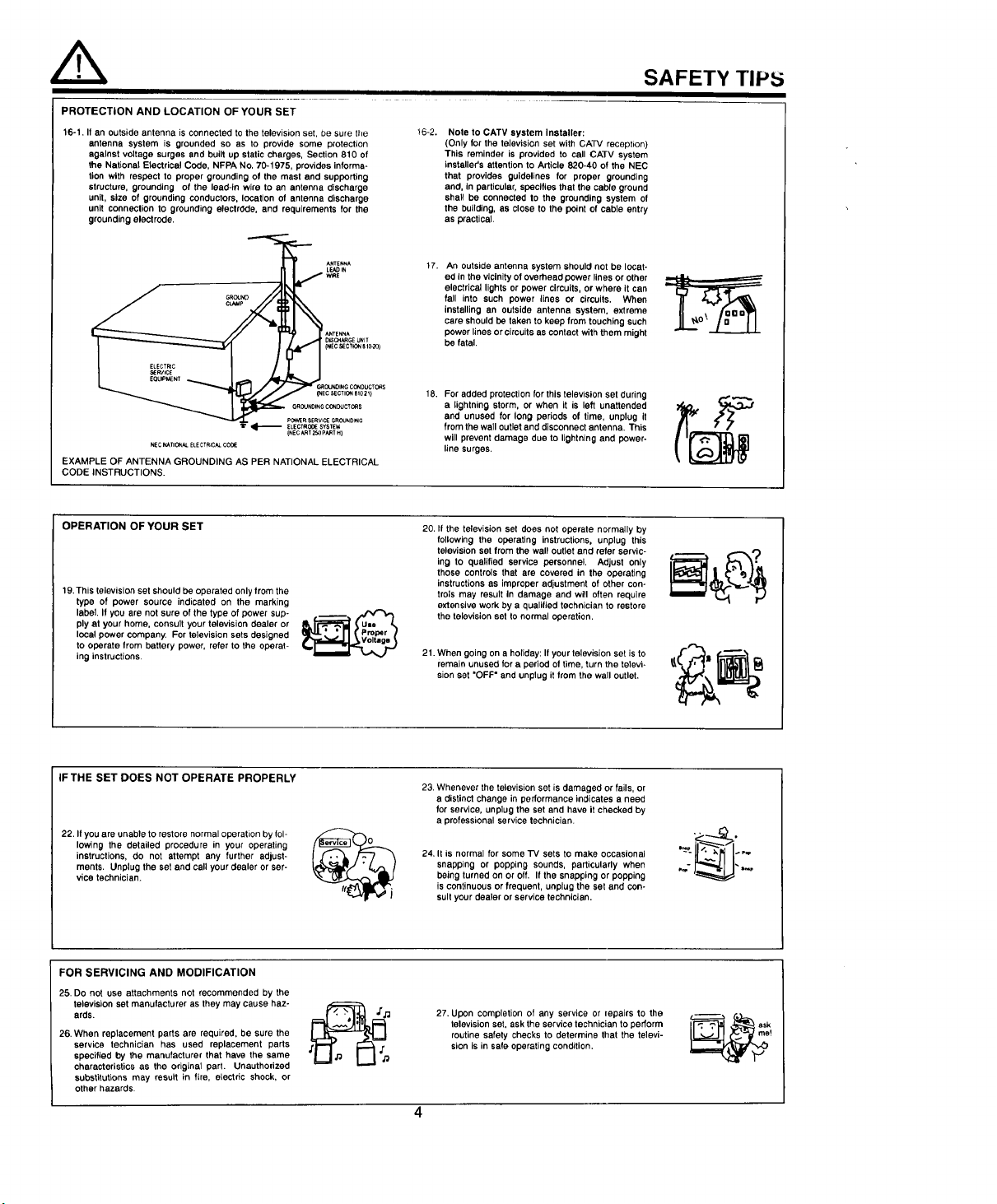
PROTECTION AND LOCATION OF YOUR SET
16-1. If an outside antenna is connected to the television set, be sure tile
antenna system is grounded so as to provide some protection
against voltage surges and built up static charges, Section 810 of
the National Electrical Code, NFPA No, 70-1975, provides informa-
tion with respect to proper grounding of the mast and supporting
structure, grounding of the lead-in wire to an antenna discharge
unit, size of grounding conductors, location of antenna discharge
unit connection to grounding electrdde, and requirements for the
grounding electrode.
LEADIN
GROUND J WRE
CL_P I ,
D_ CH,_RGE UNIT
(NEC_CT_ S10._o_
_E ANTENNA
r,_OU_INGco_Ducrc_s
ANTENNA
cSECXlO_el02_1
_OUNDINGCONDUCTCeS
POWERSERVICIE GROUNDING
ELECTROI_ SYSTEM
NE CNA TII3_AL ELECTRICAL ¢ODIE
EXAMPLE OF ANTENNA GROUNDING AS PER NATIONAL ELECTRICAL
CODE INSTRUCTIONS.
{NECART 2S0PART H}
t6-2.
Note to CATV system installer:
(Only for the television set with CATV reception)
This reminder is provided to call CATV system
installer's attention to Article 820-40 of the NEC
that provides guidelines for proper grounding
and, in particular, specifies that the cable ground
shall be connected to the grounding system of
the building, as close to the point of cable entry
as practical.
17.
An outside antenna system should not be locat-
ed In the vicinityof overhead power lines or other
electrical lights or power circuits, or where it can
fall into such power lines or circuits. When
installing an outside antenna system, extreme
care should be taken to keep from touching such
power lines or circuitsas contact with them might
be fatal.
18. For added protection for this television set during
a lightning storm, or when it is left unattended
and unused for long periods of time, unplug it
from the wall outlet and disconnect antenna. This
will prevent damage due to lightning and power-
line surges.
SAFETY TIP:5
OPERATION OF YOUR SET
19.This television set should be operated only from the
type of power source indicated on the marking
label If you are not sure of the type of power sup-
ply at your home, consult your television dealer or
local power company. For television sets designed
to operate from battery power, refer to the operat-
ing instructions.
IF THE SET DOES NOT OPERATE PROPERLY
22. If you are unable to restore normal operation by fol-
lowing the detailed procedure in your operating
instructions, do not attempt any further adjust-
ments. Unplug the set and call your dealer or ser-
vice technician.
FOR SERVICING AND MODIFICATION
25. DO not use attachments not recommended by the
television set manufacturer as they may cause haz-
ards.
26.When replacement parts are required, be sure the
service technician has used replacement parts
specified by the manufacturer that have the same
characteristics as the origins1 part. Unauthorized
substitutions may result in fire, electric shock, or
other hazards.
20. if the television set does not operate normally by
following the operating instructions, unplug this
television set from the wall outlet and refer servic-
ing to qualified service personnel. Adjust only
those controls that are covered in the operating
instructions as improper adjustment of other con-
trois may result In damage and will often require
extensive work by a qualified technician to restore
the television set to normal operation.
21. When going ona holiday: If your television set is to
remain unused for a period of time, turn the televi-
sion set "OFF" and unplug it from the wall outlet.
23.Whenever the television set is damaged or fails, or
a distinct change in performance indicates a need
for service, unplug the set and have it checked by
a professional service technician.
24, It is normal for some "IV sets to make occasional
snapping or popping sounds, particularly when
being turned on or off. If the snapping or popping
is continuous or frequent, unplug the set and con-
sult your dealer or service technician.
27. Upon completion of any service or lepaJrs to the
television set, ask the service technician to perform
routine safety checks to determine that the televi-
sion is in safe operating condition.
PICTURE CAUTIONS
Continuous on-screen displays such as
video games, stock market quotations,
computer generated graphics, and other
fixed (non-moving) patterns can cause per-
manent damage to projection television
WARNING
receivers. Such "PATTERN BURNS" con-
stitute misuse and are NOT COVERED by
your Hitachi Factory Warranty.
When using the Picture-in-Picture function, the sub-picture should not be left permanently
in one corner of the screen or a "PATTERN BURN" may develop over a long period of time.
This projection television receiver was intended mainly for the private viewing of programs
broadcast by TV stations and cable companies and programs from other video sources.
Public viewing may require prior authorization from the broadcaster or owner of the video
program.
5
ACCESSORIES
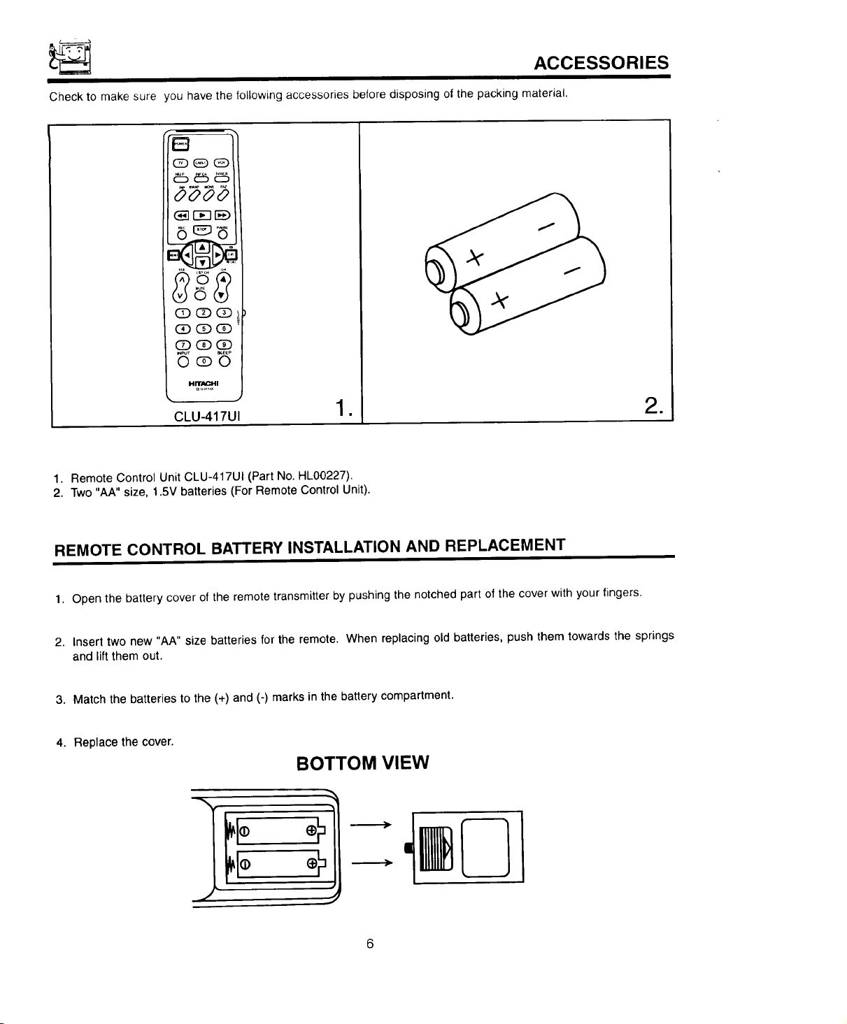
Checktomakesure
you have the followingaccessories before disposing of the packing material.
B
6_6
©_o
HITACHI
CLU-417UI
1. Remote Control Unit CLU-417UI (Part No. HL00227),
2. Two "AA" size, 1.5V batteries (For Remote Control Unit).
• =
REMOTE CONTROL BATTERY INSTALLATION AND REPLACEMENT
1. Open the battery cover of the remote transmitter by pushing the notched part of the cover with your fingers.
2. Insert two new "AA" size batteries for the remote. When replacing old batteries, push them towards the springs
and lift them out.
3. Match the batteries to the (+) and (-) marks in the battery compartment.
4. Replace the cover.
BOTTOM VIEW
HOW TO SET UP YOUR NEW HITACHI PROJECTION TV
ANTENNA
Unless yourTV is connected to a cable TV system or to a centralized antenna system, a good outdoor color TV anten-
na is recommended for best performance. However, if you are located in an exceptionally good signal area that is free
from interference and multiple image ghosts, an indoor antenna may be sufficient.
LOCA"t'tON
Select an area where sunlight or bright indoor illumination will not fall directly on the picture screen. Also, be sure that
the location selected allows a free flow of air to and from the perforated back cover of the set.
To avoid cabinet warping, cabinet color changes, and increased chance of set failure, do not place the TV where tem-
peratures can become excessively hot. For example, in direct sunlight or near a heating appliance, etc.
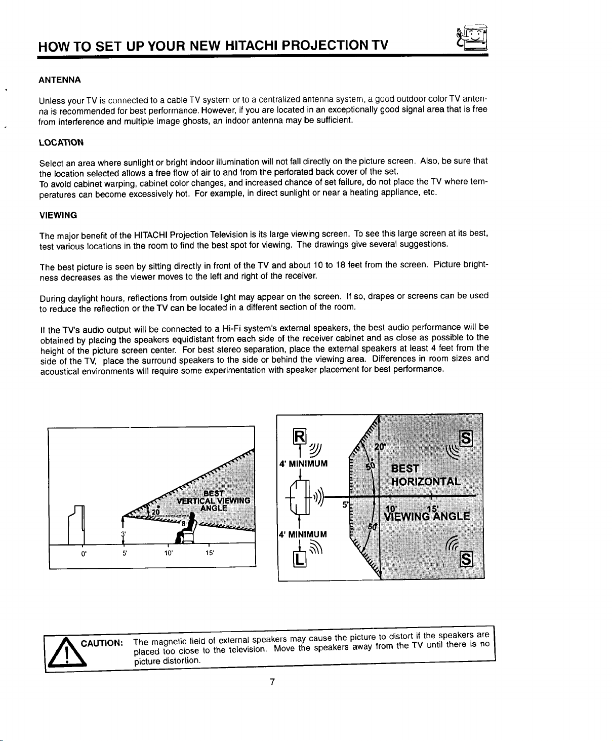
VIEWING
The major benefit of the HITACHI Projection Television is its large viewing screen. To see this large screen at its best,
test various locations in the room to find the best spot for viewing. The drawings give several suggestions.
The best picture is seen by sitting directly in front of the TV and about 10 to 18 feet from the screen. Picture bright-
ness decreases as the viewer moves to the left and right of the receiver.
During daylight hours, reflections from outside light may appear on the screen. If so, drapes or screens can be used
to reduce the reflection or the TV can be located in a different section of the room.
It the TV's audio output will be connected to a Hi-Fi system's external speakers, the best audio performance will be
obtained by placing the speakers equidistant from each side of the receiver cabinet and as close as possible to the
height of the picture screen center. For best stereo separation, place the external speakers at least 4 feet from the
side of the TV, place the surround speakers to the side or behind the viewing area. Differences in room sizes and
acoustical environments will require some experimentation with speaker placement for best performance.
AUTION:
4' MINIMUM
4' MINIMUM
10' 15'
The magnetic field of external speakers may cause the picture to distort if the speakers are I
placed too close to the television. Move the speakers away from the TV until there is no
picture distortion.
7
/
!
HOOK-UP CABLES AND CONNECTORS
Most video/audio connections between components can be made with shielded video and audio cables that have
phono connectors. For best performance, video cables should use 75-Ohm coaxial shielded wire. Cables can be pur-
chased from most stores that sell audio/video products. Below are illustrations and names of common connectors.
Before purchasing any cables, be sure of the output and input connector types required by the various components.
Also make sure the cables are the correct length.
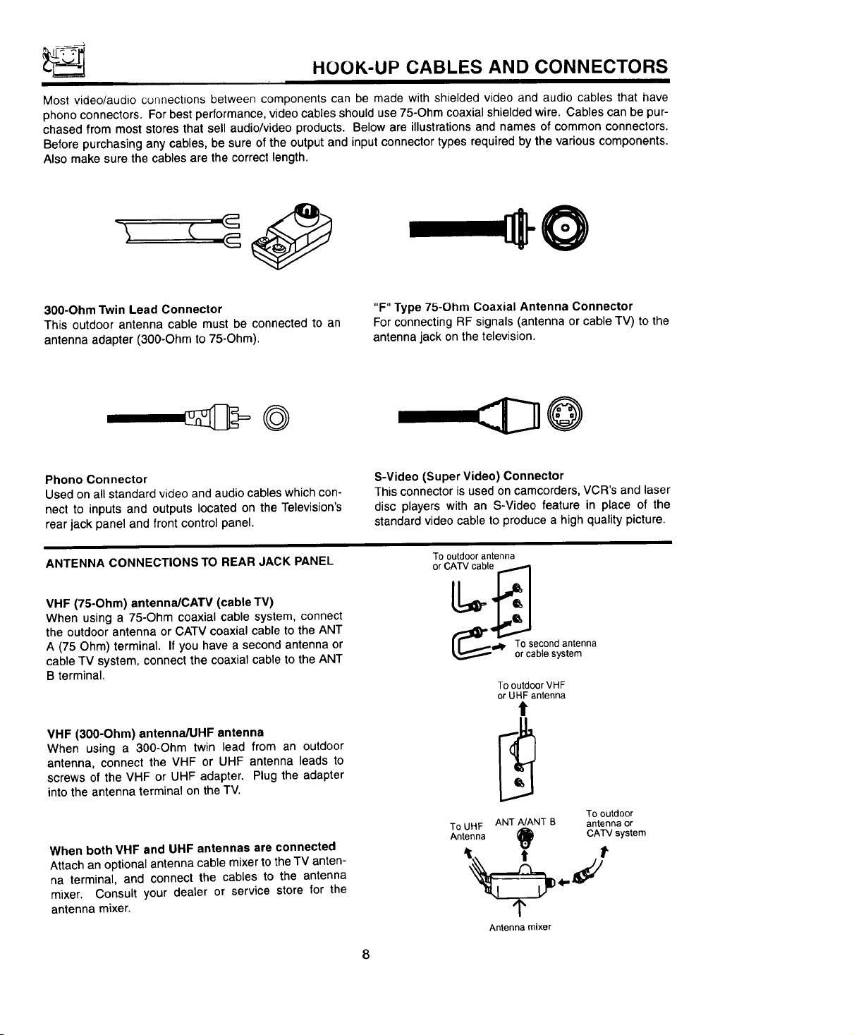
300-Ohm Twin Lead Connector
This outdoor antenna cable must be connected to an
antenna adapter (300-Ohm to 75-Ohm).
Phono Connector
Used on all standard video and audio cables which con-
nect to inputs and outputs located on the Television's
rear jack panel and front control panel.
ANTENNA CONNECTIONS TO REAR JACK PANEL
VHF (75-Ohm) antenna/CATV (cable TV)
When using a 75-Ohm coaxial cable system, connect
the outdoor antenna or CATV coaxial cable to the ANT
A (75 Ohm) terminal. If you have a second antenna or
cable TV system, connect the coaxial cable to the ANT
B terminal.
"F" Type 75-Ohm Coaxial Antenna Connector
For connecting RF signals (antenna or cable TV) to the
antenna jack on the television.
©
S-Video (Super Video) Connector
This connector is used on camcorders, VCR's and laser
disc players with an S-Video feature in place of the
standard video cable to produce a high quality picture.
To outdoor antenna
o
_l_d D, To second antenna
or cable system
To outdoor VHF
or UHF antenna
VHF (300-Ohm) antenna/UHF antenna
When using a 300-Ohm twin lead from an outdoor
antenna, connect the VHF or UHF antenna leads to
screws of the VHF or UHF adapter. Plug the adapter
intothe antenna terminal on the TV.
When both VHF and UHF antennas are connected
Attach an optionalantenna cable mixer tothe TV anten-
na terminal, and connect the cables to the antenna
mixer. Consult your dealer or service store for the
antenna mixer.
To UHF ANT A/ANT B antenna or
To outdoor
Antenna Q CATV system
Antenna mixer
8
FRONT PANEL CONTROLS
FRONT VIEW
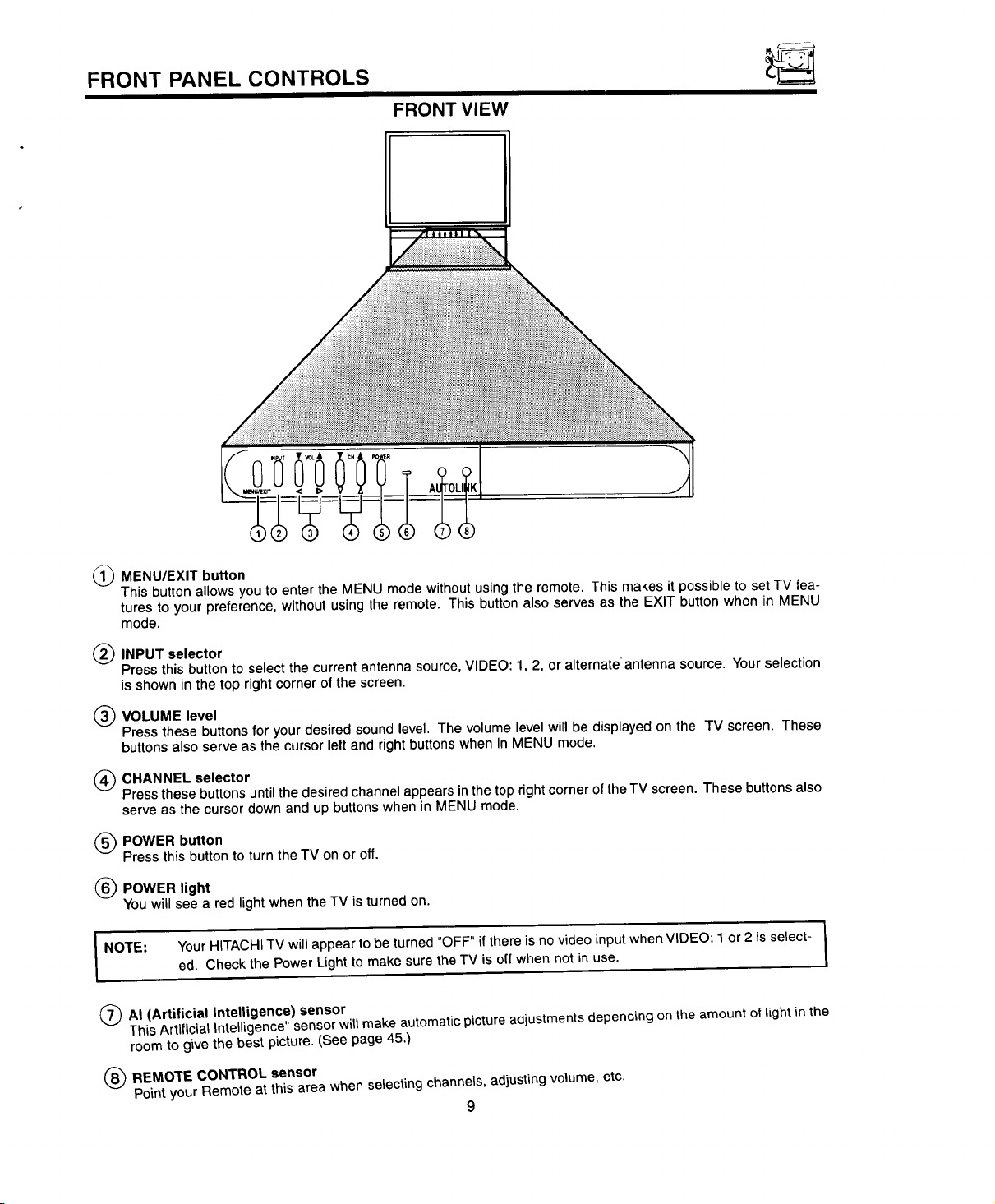
1_ MENU/EXIT button
This button allows you to enter the MENU mode withoutusing the remote, This makes it possible to set TV lea-
tures to your preference, without using the remote. This button also serves as the EXIT button when in MENU
mode.
(_) INPUT selector
Press thisbutton to select thecurrent antenna source,VIDEO: 1, 2, or alternate antenna source, Your selection
is shown in the top right corner ofthe screen.
(_) VOLUME level
Press these buttons for your desired sound level. The volume level will be displayed on the TV screen. These
buttons also serve as the cursor left and right buttons when in MENU mode.
(_) CHANNEL selector
Press these buttons until the desired channel appears in the top right corner of the TV screen. These buttons also
serve as the cursor down and up buttons when in MENU mode.
(_) POWER button
Press thisbutton to turnthe TV on or off.
(_) POWER light
You will see a red light when the TV is turned on.
I NOTE: Your HITACHITV will appear to be turned "OFF" if there is no video input when VIDEO: 1 or 2 is select-
(_)AI (Artificial Intelligence) sensor
This ArtificialIntelligence" sensor will make automatic picture adjustments depending on the amount of light inthe
ed. Check the Power Light to make sure the TV is off when not in use. !
room to give the best picture. (See page 45.)
/
(_) REMOTE CONTROL sensor
Point your Remote at this area when selecting channels, adjusting volume, etc.
9
REAR PANEL JACKS
©
®
S-VIDEO
+o
L,...I_ CONVERTER
MATRIX
SURROUND
o
ANT B
0
k
(
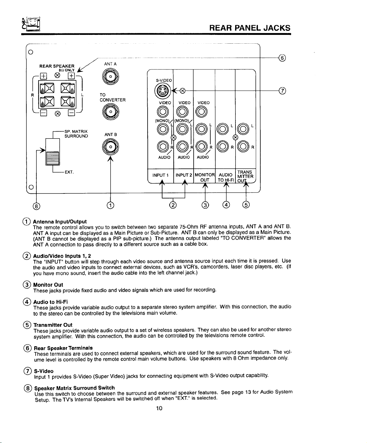
(_ Antenna Input/Output
The remote controlallows you to switch between two separate 75-Ohm RF antenna inputs,ANT A and ANT B.
ANT A inputcan be displayedas a Main Picture or Sub-Picture. ANT B can only be displayedas a Main Picture.
(ANT B cannot be displayed as a PIP sub-picture.) The antenna output labeled "TO CONVERTER" allows the
ANT A connectionto pass directly to a differentsource such as a cable box.
(_ Audio/Video Inputs 1,2
The "INPUT" button will step througheach video sourceand antenna source inputeach time it ispressed. Use
the audio and video inputs to connect external devices, such as VCR's, camcorders, laser disc players, etc. (If
you have mono sound, insertthe audiocable into the left channel jack.)
(_ Monitor Out
These jacks provide fixed audio and video signalswhich are used for recording.
(_) Audio to Hi-Fi
These jacks provide variable audio output to a separate stereo system amplifier. With this connection, the audio
to the stereo can be controlled by the televisions main volume.
(_) Transmitter Out
These jacks provide variable audio output to a set of wireless speakers. They can also be used for another stereo
system amplifier. With thisconnection, the audiocan be controlledby the televisionsremote control.
(_) Rear Speaker Terminals
These terminals are usedto connect externalspeakers, which are used forthe surroundsound feature. The vol-
ume level is controlledby the remote control main volume buttons. Use speakers with8 Ohm impedance only.
(_ S-Video
Input 1 provides S-Video (Super Video) jacks for connecting equipment with S-Video output capability.
(_) Speaker Matrix Surround Switch
Use this switch to choose between the surround and external speaker features. See page 13 for Audio System
Setup. The TV's Internal Speakers will be switchedoff when "EXT." is selected.
10
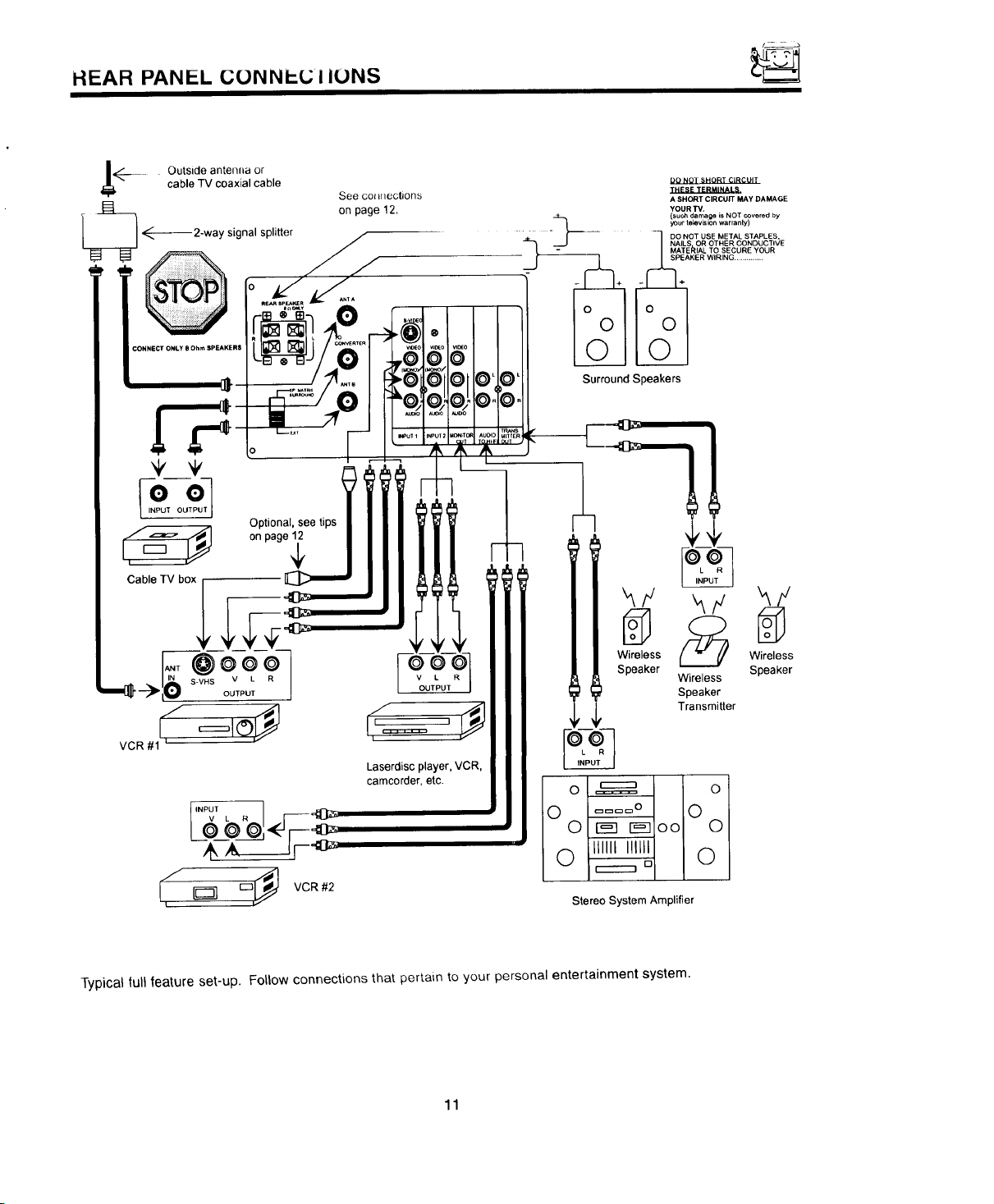
HEAR PANEL C(..)NNI-L; I IUNS
See CO_nections
on page 12.
Optional, see tips
Surround Speakers
DO NOT SHORT CIRCUIT
THESE TERMINALS.
A SHORT CIRCUIT MAY DAMAGE
YOUR TV.
such damage is NOT covered by
yourtelev skinwarran y
DO NOT USE METAL STAPLES,
NAILS OR OTHER CONDUCTIVE
MATEI_IAL TO SECURE YOUR
SPEAKER WIRING ..............
on page_
KF hY _Y
Wireless Wireless
Speaker Wireless Speaker
Laserdisc player, VCR,
camcorder, etc.
@@_._ 0 r_ r-_oo 0
1 o ....o o
i-_ Q ilull i11HI Q
/
I,
Typical full leature set-up. Follow connections that pertain to your personal entertainment system.
VCR#2
0 ==,=,== 0
D
Stereo System Amplifier
Speaker
Transmitter
11
REAR SPEAKER TERMINAL CONNECTIONS
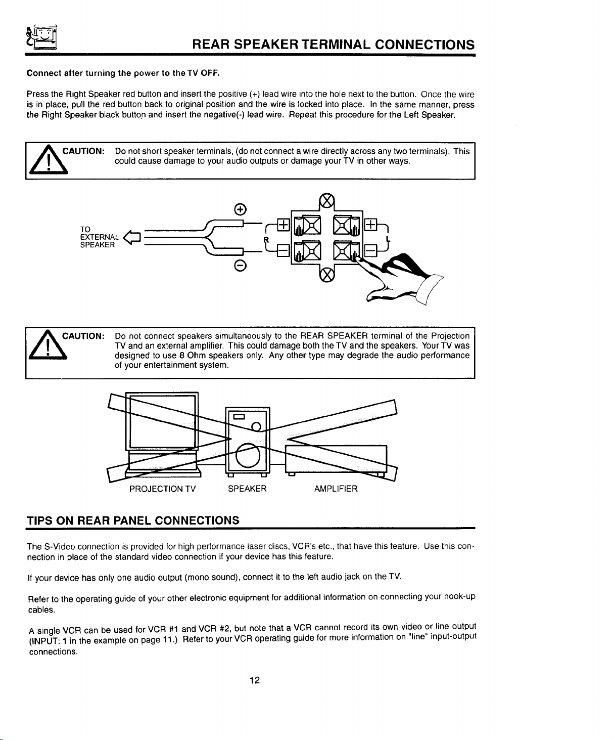
Connect after turning the power to the TV OFF.
Press the Right Speaker red button and insertthe positive (÷) lead wire into the hole next to the button. Once the wire
is in place, pull the red button back to original position and the wire is locked into place. In the same manner, press
the Right Speaker black button and insert the negative(-) lead wire. Repeat this procedure for the Left Speaker.
[ ,_AUTION: Do not short speaker terminals, (do not connect a wire directly across any two terminals). This
could cause damage to your audio outputs or damage your TV in other ways.
®
TO
EXTERNAL,_
SPEAKER
®
Do not connect speakers simultaneously to the REAR SPEAKER terminal of the Projection
TV and an external amplifier. This could damage both the TV and the speakers. YourTV was
,_AUTION:
designed to use 8 Ohm speakers only. Any other type may degrade the audio performance
of your entertainment system.
/
C
PROJECTION TV SPEAKER AMPLIFIER
TIPS ON REAR PANEL CONNECTIONS
The S-Video connection is provided for high performance laser discs, VCR's etc., that have this feature. Use this con-
nection in place of the standard video connection if your device has this feature.
If your device has only one audio output (mono sound), connect it to the left audio jack on the TV.
Refer to the operating guide of your other electronic equipment for additional information on connecting your hook-up
cables.
A single VCR can be used for VCR #1 and VCR #2, but note that a VCR cannot record its own video or line output
(INPUT: 1 in the example on page 11.) Refer to your VCR operating guide for more information on "line" input-output
connections.
12
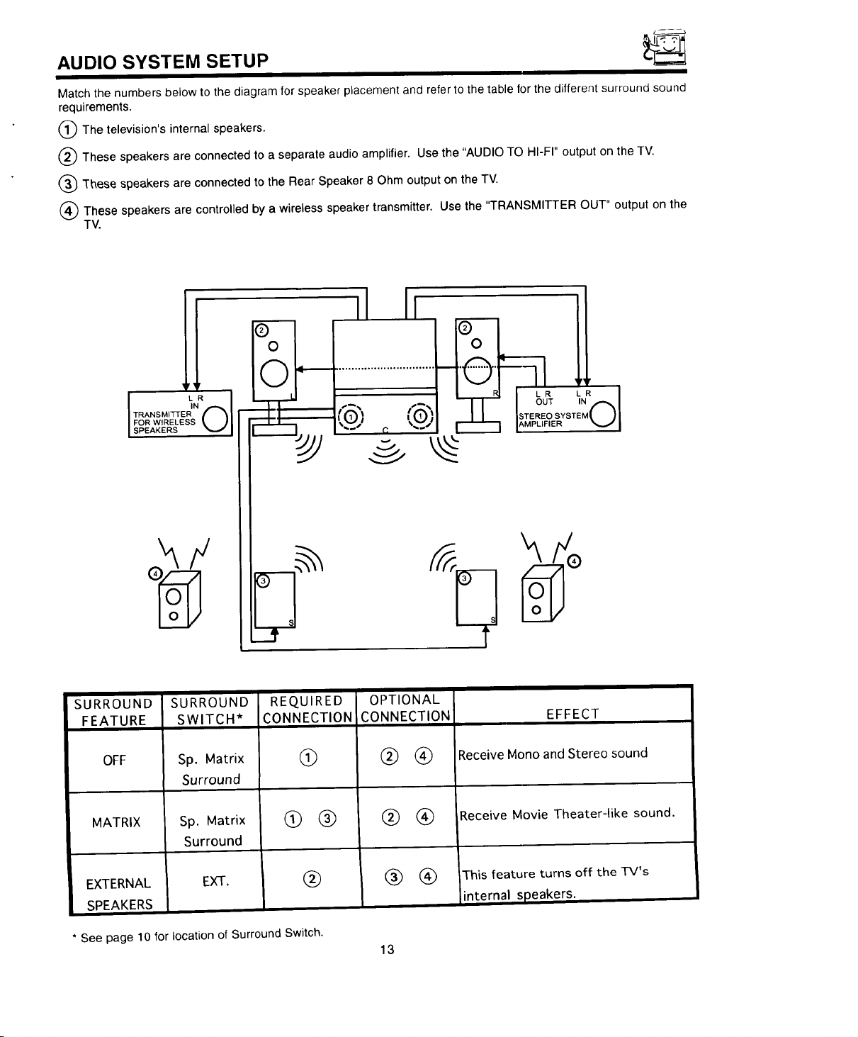
AUDIO SYSTEM SETUP
Match the numbers below to the diagram for speaker placement and refer to the table forthe different surround sound
requirements.
The television's internal speakers.
These speakers are connected to a separate audio amplifier. Use the "AUDIO TO HI-FI" output on the TV,
(_ These speakers are connected to the Rear Speaker 8 Ohm output on the TV.
These speakers are controlled by a wireless speaker transmitter. Use the "TRANSMITTER OUT" output on the
TV.
II Ii !
ii.............ii
SPEAKERS V I
SURROUND
FEATURE
OFF
MATRIX
SURROUND
SWITCH*
Sp. Matrix
Surround
Sp. Matrix
Surround
REQUIRED
CONNECTION
G
®EXTERNAL EXT.
SPEAKERS
* See page l0forlocationofSurround Switch.
OPTIONAL
CONNECTION
®®
® ®
13
EFFECT
Receive Mono andStereo sound
Receive Movie Theater-like sound.
This feature turns off the TV's
internal speakers.
1 HE GENIUS REMU I i- CONTROL ((.;LU-417UI)
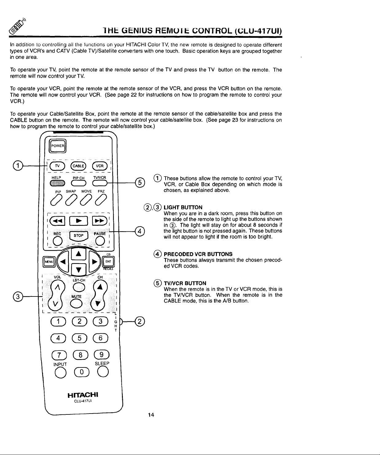
In addition tocontrolling all the functions on your HITACHI Color TV, the new remote is designed to operate different
types of VCR's and CATV (Cable TV)/Satellite converters with one touch. Basic operation keys are grouped together
in one area.
To operate your TV, point the remote at the remote sensor of the TV and press the TV button on the remote. The
remote will now control your TV.
To operate your VCR, point the remote at the remote sensor of the VCR, and press the VCR button on the remote.
The remote will now control your VCR. (See page 22 for instructions on how to program the remote to control your
VCR.)
To operate your Cable/Satellite Box, point the remote at the remote sensor of the cable/satellite box and press the
CABLE button on the remote. The remote will now control your cable/satellite box. (See page 23 for instructions on
how to program the remote to control your cable/satellite box.)
0
HELP PIP CH TVNCR
PiP SWAP MOVE FRZ
0000
V0-1,,. CH
These buttons allow the remote to control your TV,
VCR, or Cable Box depending on which mode is
chosen, as explained above.
®,®
®
I
G
H
T
LIGHT Bu'n'ON
When you are in a dark room, press this button on
the side of the remote to light up the buttons shown
in (_. The light will stay on for about 8 seconds if
the light button is not pressed again. These buttons
will not appear to light if the room is too bright.
PRECODED VCR BUTTONS
®
These buttons always transmit the chosen precod-
ed VCR codes.
TV/VCR BUT[ON
®
When the remote is inthe TV or VCR mode, this is
the TV/VCR button. When the remote is in the
CABLE mode, this is the A/B button.
INPUT SLEEP
0( 0
HITACHI
CLU..417UI
J
14
HOW TO USE THE GENIUS REMOTE TO CONTROL YOUR TV
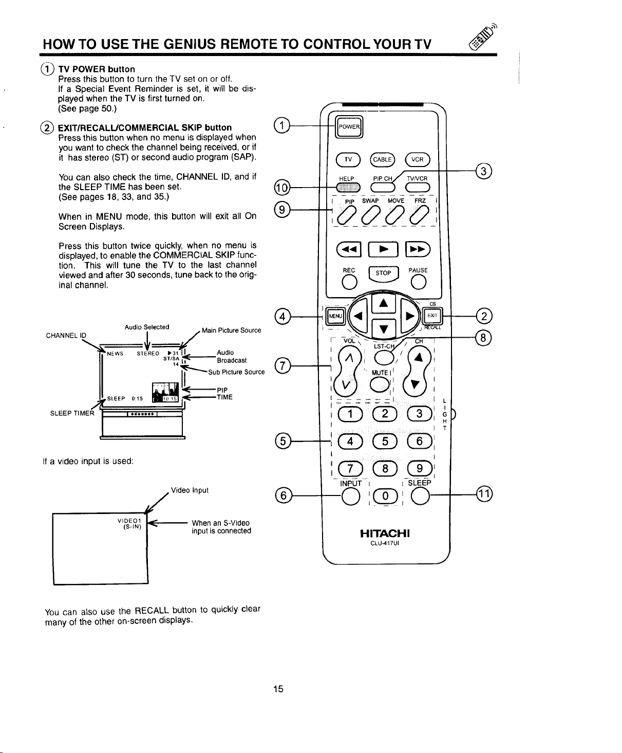
TV POWER button
Press thisbutton to turn the TV set on or off.
If a Special Event Reminder is set, it will be dis-
played when the TV is first turned on.
(See page 50.)
EXIT/RECALIJCOMMERCIAL SKIP button
Press this button when no menu is displayedwhen
you want to check the channel being received, or if
it has stereo (ST) or second audio program (SAP).
You can also check the time, CHANNEL ID, and if
the SLEEP TIME has been set.
(See pages 18, 33, and 35.)
When in MENU mode, this button will exit all On
Screen Displays.
Press this button twice quickly, when no menu is
displayed, to enable the COMMERCIAL SKIP func-
tion. This will tune the TV to the last channel
viewed and after 30 seconds, tune back to the orig-
inal channel.
CHANNEL ID
Audio Selected Main Picture Source
bNEWS v_ I
STEREO 1_31 II Audio
STISA_ Broadcast
Sub Picture Source
'k--------P, E
,SLEEP0:15 _f_--'--'_'TI
SLEEP TIMER
If a video input is used:
You can also use the RECALL button to quickly clear
many of the other on-screen displays.
J
I =oo_ooo I
t"
j Video Input
VIDEO1
(S-IN)
When an S-Video
inputis connected
®
®
HITACHI
CLU-417UI
L
H
T
©
15
HOW TO USE THE GENIUS REMOTE TO CONTROL YOUR TV
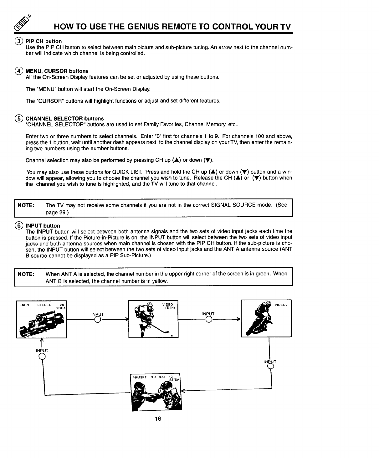
_)PIP CH button
Use the PIP CH button toselect between main picture and sub-picture tuning. An arrow next to the channel num-
ber will indicate which channel is being controlled.
(_ MENU, CURSOR buttons
All the On-Screen Display features can be set or adjusted by usingthese buttons.
The "MENU" button will start the On-Screen Display.
The "CURSOR" buttons will highlight functions or adjust and set different features.
(_) CHANNEL SELECTOR buttons
"CHANNEL SELECTOR" buttons are usedto set Family Favorites, Channel Memory, etc..
Enter two or three numbers to select channels. Enter "0" first for channels 1 to 9. For channels 100 and above,
press the 1 button, wait until another dash appears next to the channel display on your TV, then enter the remain-
ing two numbers using the number buttons.
Channel selection may also be performed by pressing CH up (A) or down (V).
You may also use these buttons for QUICK LIST. Press and hold the CH up (A) or down (V) button and a win-
dow will appear, allowing you to choose the channel you wish to tune. Release the CH (A) or (V) button when
the channel you wish to tune is highlighted, and the TV will tune to that channel.
I NOTE:
(_ INPUT button
The INPUT button will select between both antenna signals and the two sets of video input jacks each time the
button is pressed. If the Picture-in-Picture is on, the INPUT button will select between the two sets of video input
jacks and both antenna sources when main channel is chosen with the PIP CH button. If the sub-picture is cho-
sen, the INPUT button will select between the two sets of video input jacks and the ANT A antenna source (ANT
B source cannot be displayed as a PIP Sub-Picture.)
I NOTE:
The TV may not receive some channels if you are not in the correct SIGNAL SOURCE mode. (See I
page 29.)
When ANT A is selected, the channel number inthe upper right corner of the screen is in green. When I
ANT B is selected, the channel number is inyellow.
VIDEO1
(S-IN)
INPUT
.©
_1 _1_ VIDEO2
T
INPUT
_NPU3-
I
I
I
I
l
16
HOW TO USE THE GENIUS REMOTE TO CONTROL YOUR TV
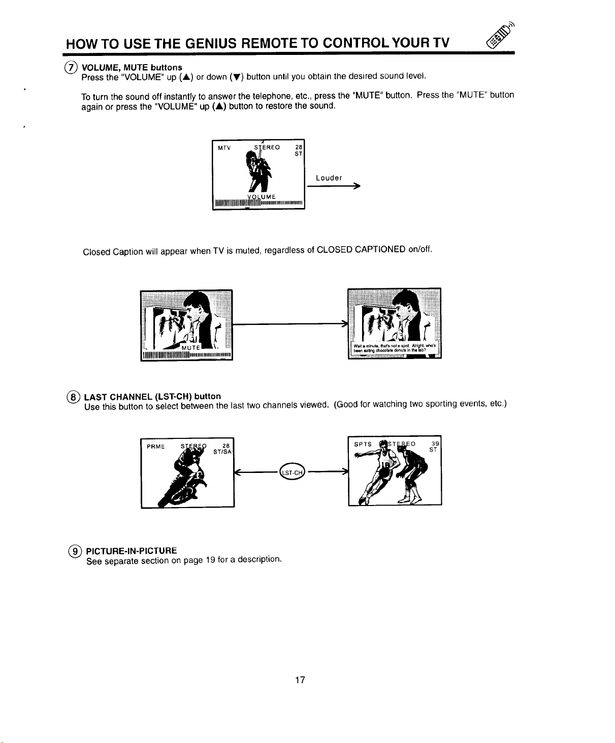
(_ VOLUME, MUTE buttons
Press the "VOLUME" up (A) or down (y) button until you obtain the desired sound level.
To turn the sound off instantly to answer the telephone, etc., press the "MUTE" button. Press the "MUTE" button
again or press the "VOLUME" up (A) button to restore the sound.
Louder
Closed Caption will appear when TV is muted, regardless of CLOSED CAPTIONED on/off.
(_) LAST CHANNEL (LST-CH) button
Use this button to select between the last two channels viewed. (Good for watching two sporting events, etc.)
(_ PICTURE-IN-PICTURE
See separate section on page 19 for a description.
17
HOW TO USE THE GENIUS REMOTE TO CONTROL YOUR TV
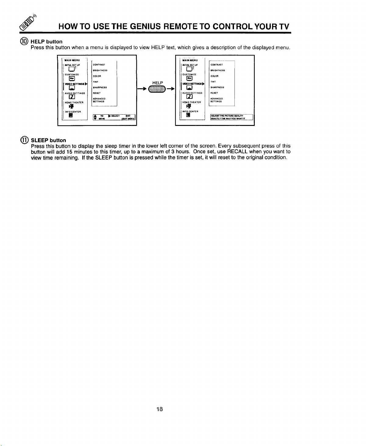
(_) HELP button
Press this button when a menu is displayed to view HELP text, which gives a description of the displayed menu.
MAIN MENU
I%"
IAUO_ E ......
CONTRAST
j emONTNESS
COLOR
TINT HELP
RESET
AOVANCEO
SETTINGS
MAIN MENU
/.,T OO
i,uo ,......
CONTRAST
BRIGHTNESS
COtOR
TINT
SHARPNE58
R_BET
ADVANCE°
SETTINGS
IN°;ii......
IINF_ .....
(_ SLEEP button
Press this button to display the sleep timer in the lower left corner of the screen. Every subsequent press of this
button will add 15 minutes to this timer, up to a maximum of 3 hours. Once set, use RECALL when you want to
view time remaining. If the SLEEP button is pressed while the timer is set, it will reset to the original condition.
It ,o • ......
18
 Loading...