

Hitachi 55DMX01W Service Manual

PA
No. 0143
HITACHI
DLPTM1 Chassis NTSC
SAFETY PRECAUTIONS 2
PRODUCT SAFETY NOTICE 3
SERVICING PRECAUTIONS 4
AGENCY REGULATORY INFORMATION 8
TECHNICAL SPECIFICATIONS 9
PLUG AND PLAY/TRADEMARK ACKNOWLEDGEMENT 10
CONTENT OF ADJUSTMENTS 11
FRONT PANEL AND REAR PANEL OPERATION 12
LAMP REPLACEMENT 19
TV/PC FEATURE EXPLANATION 23
PC/COMPONENT INPUT SIGNAL TIMING SPECIFICATION 37
HEAT RUN LED INDICATOR OPERATION 46
PWB ADJUSTMENTS 50
OPTICAL ENGINE REPAIR/REPLACEMENT PARTS 80
RASTER POSITION ADJUSTMENT 81
TROUBLESHOOTING FLOWCHARTS 115
DC VOLTAGES 127
WAVEFORMS 142
REPLACEMENT PARTS LIST 153
EXPLODED VIEW 184
PRINTED CIRCUIT BOARDS 185
WIRING DRAWING 191
CHASSIS BLOCK DIAGRAM 192
BASIC CIRCUIT DIAGRAM 193
FINAL WIRING DIAGRAM 208
OPTICAL ENGINE REMOVAL PROCEDURE 213
OPTICAL ENGINE ALIGNMENT PROCEDURE 246
55DMX01W
R/C: CLU-579TSI
CAUTION: Before servicing this chassis, it is important that the service technician read the
“Product Safety Notices” in this service manual.
SAFETY NOTICE
USE ISOLATION TRANSFORMER WHEN SERVICING
Components having special safety characteristics are identified by a on the
parts list in this Service Data and its supplements and bulletins. Before servicing
the chassis, it is important that the service technician read and follow the “Safety
Precautions” and Product Safety Notices” in this Service Manual.
SPECIFICATIONS AND PARTS ARE SUBJECT TO CHANGE FOR IMPROVEMENT
NOVEMBER 2000 HHEA-MANUFACTURING DIVISION
!
2
NOTICE: Comply with all cautions and safety-related notes
located on or inside the cabinet and on the chassis or optic unit.
WARNING: Since the chassis of this receiver is connected to
one side of the AC power supply during operation, whenever the
receiver is plugged in service should not be attempted by anyone unfamiliar with the precautions necessary when working on
this type of receiver.
The following precautions should be observed:
1. Do not install, remove, or handle the optic unit in any manner
unless shatterproof goggles are worn. People not so equipped
should be kept away from the optic unit while handling.
2. When service is required, an isolation transformer should be
inserted between power line and the receiver before any service is performed on a ÒHOTÓ chassis receiver.
3. When replacing a chassis in the receiver, all the protective
devices must be put back in place, such as barriers, nonmetallic knobs, adjustment and compartment cover-shields, isolation
resistors, capacitors, etc.
4. When service is required, observe the original lead dress.
5. Always use the manufacturerÕs replacement components.
Critical components as indicated on the circuit diagram should
not be replaced by another manufacturerÕs. Furthermore, where
a short circuit has occurred, replace those components that
indicate evidence of overheating.
6. Before returning a serviced receiver to the customer, the service technician must thoroughly test the unit to be certain that it
is completely safe to operate without danger of electrical shock,
and be sure that no protective device built into the receiver by
the manufacturer has become defective, or inadvertently
defeated during servicing.
Therefore, the following checks should be performed for the continued protection of the customer and service technician.
Leakage Current Cold Check
With the AC plug removed from the 120V AC 60Hz source, place
a jumper across the two plug prongs. Using an insulation tester
(DC500V), connect one lead to the jumpered AC plug and touch
the other lead to each exposed metal part (antennas, screwheads,
metal overlays, control shafts, etc.), particularly any exposed
metal part having a return path to the chassis should have a minimum resistor reading of 2.4M⏲ and a maximum resistor reading
of 5.2M⏲. Any resistance value below or above this range indicates an abnormality which requires corrective action. An exposed
metal part having a return path to the chassis will indicate an open
circuit.
AC LEAKAGE TEST
ANY MEASUREMENTS NOT WITHIN THE LIMITS OUTLINED
ABOVE ARE INDICATIVE OF A POTENTIAL SHOCK HAZARD
AND MUST BE CORRECTED BEFORE RETURNING THE
RECEIVER TO THE CUSTOMER.
SAFETY PRECAUTIONS
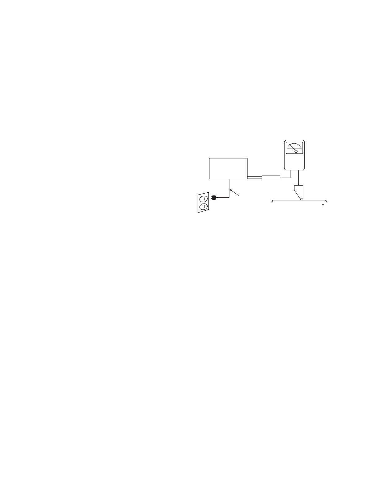
Leakage Current Hot Check
Plug the AC line cord directly into a 120V AC 60Hz outlet (do not use
an isolated transformer for this check). Turn the AC power ON. Using
a Leakage Current Tester (SimpsonÕs Model 229 or equivalent),
measure for current from all exposed metal parts of the cabinet
(antennas, screwheads, overlays, control shafts, etc.) particularly
any exposed metal
part having a return path to the chassis or to a
known earth ground (water pipe, conduit, etc.). Any current measured must not exceed 0.5 milliamps.
(READING
SHOULD NOT
BE ABOVE
0.5 mA)
-
+
EARTH
GROUND
DEVICE
UNDER
TEST
2-WIRE CORD
ALSO TEST WITH
PLUG REVERSED (USING
AC ADAPTER PLUS
AS REQUIRED)
TEST ALL
EXPOSED
METAL
SURFACES
LEAKAGE
CURRENT
TESTER
3
Many electrical and mechanical parts in HITACHI television
receivers have special safety-related characteristics. These are
often not evident from visual inspection nor can the protection
afforded by them necessarily be obtained by using replacement
components rated for higher voltage, wattage, etc. Replacement
parts which have these special safety characteristics are identified
in this Service Manual.
Electrical components having such features are identified with an
! mark in the schematics and parts list in this Service Manual.
The use of a substitute replacement component which does not
have the same safety characteristics as the HITACHI-recommended replacement component, shown in the parts list in this
Service Manual, may create shock, fire, X-radiation, or other hazards.
Production safety is continuously under review and new instructions are issued from time to time. For the latest information,
always consult the current HITACHI Service Manual. A subscription to, or additional copies of HITACHI Service Manuals may be
obtained at a nominal charge from HITACHI Sales Corporation.
Ultraviolet Radiation
OPTIC UNIT: The primary source of Ultraviolet Radiation in this
receiver is the optic unit. The optic unit utilized in this chassis is
specially constructed to limit Ultraviolet Radiation emissions. For
continued Ultraviolet Radiation protection, the replacement optic
unit must be the same type as the original HITACHI-approved
type.
Service Personnel - WARNING
Eye damage may result from directly viewing the light produced by
the lamp used in this product. Always turn off lamp before opening optic unit. Ultraviolet radiation eye protection required during
servicing.
When troubleshooting and making test measurements in a receiver with an excessive high voltage problem, avoid being unnecessarily close to the optic unit and the high voltage component.
Do not operate the chassis longer than is necessary to locate the
cause of excessive voltage.
This Service Manual is intended for qualified service technicians; it is not meant for the casual do-it-yourselfer. Qualified
technicians have the necessary test equipment and tools, and
have been trained to properly and safely repair complex products such as those covered by this manual. Improperly performed repairs can adversely affect the safety and reliability of
the product and may void warranty. Consumers should not risk
trying to do the necessary repairs and should refer to a qualified service technician.
WARNING
Lead in solder used in this product is listed by the California Health
and Welfare agency as a known reproductive toxicant which may
cause birth defects or other reproductive harm (California Health
and Safety Code, Section 25249.5).
When servicing or handling circuit boards and other components which contain lead in solder, avoid unprotected skin
contact with solder. Also, when soldering do not inhale any
smoke or fumes produced.
SAFETY NOTICE
USE ISOLATION TRANSFORMER
WHEN SERVICING
Components having special safety characteristics identified by
!
on the parts list in this service manual and its
supplements and bulletins. Before servicing this product, it
is important that the service technician read and follow the
ÒSafety PrecautionsÓ and the ÒProduct Safety NoticesÓ in
this Service Manual.
For continued X-Radiation protection, replace optic unit
with original type or HITACHI equivalent type.
POWER SOURCE
This television receiver is designed to operate on 120
Volts/60Hz, AC house current. Insert the power cord into
a 120 Volts/60Hz outlet.
NEVER CONNECT THE TV TO OTHER THAN THE
SPECIFIED VOLTAGE OR TO DIRECT CURRENT.
CAUTION!
The following symbol near the fuse indicates fast operating fuse (to be replaced). Fuse ratings appear within the
symbol.
Example:
The rating of fuse F901 is 8.0A-125V.
Replace with the same type of fuse for continued protection against fire.
PRODUCT SAFETY NOTICE
125V
8A
F901

4
CAUTION: Before servicing instruments covered by this service
data and its supplements and addenda, read and follow the SAFETY PRECAUTIONS on page 2 of this publication.
NOTE: If unforseen circumstances create conflict between the following SERVICING PRECAUTIONS and any of the SAFETY PRECAUTIONS on page 2 of this publication, always follow the SAFETY
PRECAUTIONS.
Remember: Safety First.
General Servicing Guidelines
1. Always unplug the instrument AC power cord from the AC power
source before:
a. Removing or reinstalling any component, circuit board,
module, or any other instrument assembly.
b. Disconnecting or reconnecting any instrument electrical
plug or other electrical connection.
c. Connecting a test substitute in parallel with an electrolyt-
ic capacitor in the instrument.
CAUTION: A wrong part substitution or incorrect
polarity installation of electrolytic
capacitors may result in an
explosion hazard.
2. Do not spray chemicals on or near this instrument or any of its
assemblies.
3. Unless specified otherwise in these service data, clean electrical contacts by applying the following mixture to the contacts
with a pipe cleaner, cotton-tipped stick or comparable nonabrasive applicator: 10% (by volume) Acetone and 90% (by volume)
ispropyle alchohol (90%-99% strength).
CAUTION: This is a flammable mixture. Unless specified
otherwise in these service data, lubrication of
contacts is not required.
4. Do not defeat any plug/socket B+ voltage interlocks with which
instruments covered by this service data might be equipped.
5. Do not apply AC power to this instrument and/or any of its electrical assemblies unless all solid-state device heat-sinks are correctly installed.
6. Always connect the test instrument ground lead to the appropriate instrument chassis ground before connecting the test instrument positive lead. Always remove the test instrument ground
lead last.
7. Use with this instrument only the test fixtures specified in this
service data.
CAUTION: Do not connect the test fixture ground strap to
any heatsink in this instrument.
Electrostatically Sensitive (ES) Devices
Some semiconductor (solid state) devices can be damaged easily
by static electricity. Such components commonly are called
Electrostatically Sensitive (ES) Devices. Examples of typical ES
devices are integrated circuits and some field-effect transistors and
semiconductor ÒchipÓ components. The following techniques should
be used to help reduce the incidence of component damage caused
by static electricity.
1. Immediately before handling any semiconductor component or
semiconductor-equipped assembly, drain off any electrostatic
charge on your body by touching a known earth ground.
Alternatively, obtain and wear a commercially available discharging wrist strap device, which should be removed for potential shock reasons prior to applying power to the unit under test.
2. After removing an electrical assembly equipped with ES
devices, place the assembly on a conductive surface such as
aluminum foil, to prevent electrostatic charge build-up or exposure of the assembly.
3. Use only a grounded-tip soldering iron to solder or desolder ES
devices.
4. Use only an anti-static type solder removal device. Some solder removal devices not classified as Òanti-staticÓ can generate
electrical charges sufficient to damage ES device.
5. Do not use freon-propelled chemicals. These can generate
electrical charges sufficient to damage ES devices.
6. Do not remove a replacement ES device from its protective
package until immediately before you are ready to install it.
(Most replacement ES devices are packaged with leads electrically shorted together by conductive foam, aluminum foil or
comparable conductive material.)
7. Immediately before removing the protective material from the
leads of a replacement ES device, touch the protective material
to the chassis or circuit assembly into which the device will be
installed.
CAUTION: Be sure no power is applied to the chassis or
circuit, and observe all other safety precautions.
8. Minimize bodily motions when handling unpackaged replacement ES devices. (Otherwise harmless motion such as the
brushing together of your clothes fabric or the lifting of your foot
from a carpeted floor can generate static electricity sufficient to
damage an ES device.)
SERVICING PRECAUTIONS
5
General Soldering Guidelines
1. Use a grounded-tip, low-wattage soldering iron and appropriate
tip size and shape that will maintain tip temperature within the
range 500¡F to 600¡F.
2. Use an appropriate gauge of resin-core solder composed of 60
parts tin/40 parts lead.
3. Keep the soldering iron tip clean and well-tinned.
4. Thoroughly clean the surfaces to be soldered. Use a small wirebristle (0.5 inch or 1.25 cm) brush with a metal handle. Do not
use freon-propelled spray-on cleaners.
5. Use the following desoldering technique.
a. Allow the soldering iron tip to reach normal temperature
(500¡F to 600¡F).
b. Heat the component lead until the solder melts. Quickly
draw away the melted solder with an anti-static, suctiontype solder removal device or with solder braid.
CAUTION: Work quickly to avoid overheating the circuit
board printed foil.
6. Use the following soldering technique.
a. Allow the sodering iron tip to reach normal temperature
(500¡F to 600¡F).
b. First, hold the soldering iron tip and solder strand against
the component lead until the solder melts.
c. Quickly move the soldering iron tip to the junction of the
component lead and the printed circuit foil, and hold it
there only until the solder flows onto and around both the
component lead and the foil.
CAUTION: Work quickly to avoid overheating the circuit
board printed foil or components.
d. Closely inspect the solder area and remove any excess
or splashed solder with a small wire-bristle brush.
IC Removal/Replacement
Some Hitachi unitized chassis circuit boards have slotted holes
(oblong) through which the IC leads are inserted and then bent flat
against the circuit foil. When holes are the slotted type, the following technique should be used to remove and replace the IC. When
working with boards using the familiar round hole, use the standard
technique as outlined in paragraphs 5 and 6 above.
Removal
1. Desolder and straighten each IC lead in one operation by gently prying up on the lead with the soldering iron tip as the solder
melts.
2. Draw away the melted solder with an anti-static suction-type sol
der removal device (or with solder braid) before removing the
IC.
Replacement
1. Carefully insert the replacement IC in the circuit board.
2. Carefully bend each IC lead against the circuit foil pad and
solder it.
3. Clean the soldered areas with a small wire-bristle brush. (It is
not necessary to reapply acrylic coating to areas.)
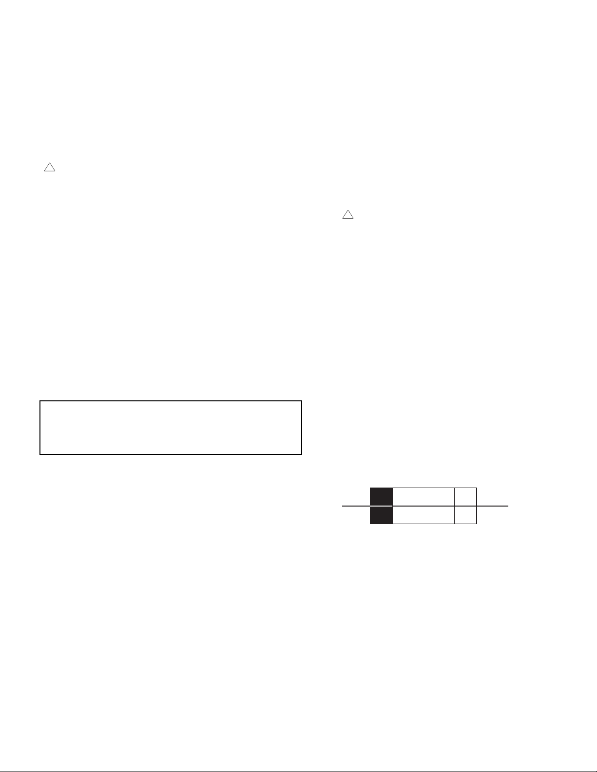
ÒSmall-signalÓ Discrete Transistor Removal/Replacement
1. Remove the defective transistor by clipping its leads as close as
possible to the component body.
2. Bend into a ÒUÓ shape the end of each of three leads remaining on the circuit board.
3. Bend into a ÒUÓ shape the replacement transistor leads.
4. Connect to replacement transistor leads to the corresponding
leads extending from the circuit board and crimp the ÒUÓ with
long nose pliers to insure metal to metal contact, then solder
each connection.
Power Output Transistor Devices Removal/Replacement
1. Heat and remove all solder from around the transistor leads.
2. Remove the heatsink mounting screw (if so equipped).
3. Carefully remove the transistor from the circuit board.
4. Insert new transistor in circuit board.
5. Solder each transistor lead, and clip off excess lead.
6. Replace heatsink.
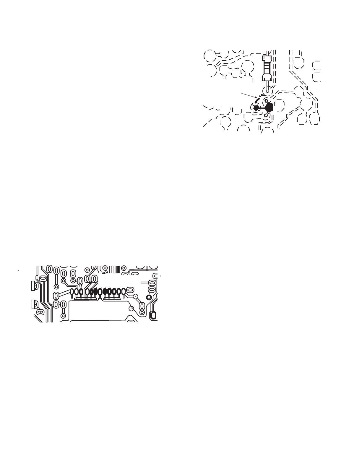
Diode Removal/Replacement
1. Remove defective diode by clipping its leads as close as possilbe to diode body.
2. Bend the two remaining leads perpendicularly to the circuit
board.
3. Observing diode polarity, wrap each lead of the new diode
around the corresponding lead on the circuit board.
4. Securely crimp each connection and solder it.
5. Inspect (on the circuit board copper side) the solder joints of
the two Òoriginal leadsÓ. If they are not shiny, reheat them
and, if necessary, apply additional solder.
Use Soldering Iron to Pry Leads
6
Fuses and conventional Resistor Removal/Replacement
1. Clip each fuse or resistor lead at top of circuit board hollow
stake.
2. Securely crimp leads of replacement component around stake
1/8 inch from top.
3. Solder the connections.
CAUTION: Maintain original spacing between the replaced
component and adjacent components and the
circuit board, to prevent excessive component
temperatures.
Circuit Board Foil Repair
Excessive heat applied to the copper foil of any printed circuit board
will weaken the adhesive that bonds the foil to the circuit board,
causing the foil to separate from, or Òlift-offÓ the board. The following guidelines and procedures should be followed whenever this
condition is encountered.
In Critical Copper Pattern Areas
High component/copper pattern density and/or special voltage/current characteristics make the spacing and integrity of copper pattern
in some circuit board areas more critical than in others. The circuit
foil in these area is designated as Critical Copper Pattern. Because
Critical Copper Pattern requires special soldering techniques to
ensure the maintenance of reliability and safety standards, contact
your Hitachi personnel.
At IC Connections
To repair defective copper pattern at IC connections, use the following procedure to install a jumper wire on the copper pattern side of
the circuit board. (Use this technique only on IC connections.)
1. Carefully remove the damaged copper pattern with a sharp
knife. (Remove only as much copper as absolutely necessary.)
2. Carefully scratch away the solder resist and acrylic coating (if
used) from the end of the remaining copper pattern.
3. Bend a small ÒUÓ in one end of a small-gauge jumper wire and
carefully crimp it around the IC pin. Solder the IC connection.
4. Route the jumper wire along the path of the cut-away copper
pattern and let it overlap the previously scraped end of the good
copper pattern. Solder the overlapped area, and clip off any
excess jumper wire.
At Other Connections
Use the following technique to repair defective copper pattern at
connections other than IC Pins. This technique involves the installation of a jumper wire on the component side of the circuit board.
1. Remove the defective copper pattern with a sharp knife.
Remove at least 1/4 inch of copper, to ensure hazardous condition will not exist if the jumper wire opens.
2. Trace along the copper pattern from both wire sides of the pattern break and locate the nearest component directly connected
to the affected copper pattern.
3. Connect insulated 20-gauge jumper wire from the nearest component on one side of the pattern break to the lead of the nearest component on the other side. Carefully crimp and solder the
connections.
CAUTION: Be sure the insulated jumper wire is dressed so
that it does not touch components or sharp
edges.
Frequency Synthesis (FS) Tuning Systems
1. Always unplug the instrument AC power cord before disconnecting or reconnecting FS tuning system cables and before
removing or inserting FS tuning system modules.
2. The FS tuner must never be disconnected from the FS tuning
control module while the power is applied to the instrument.
3. When troubleshooting intermittent problems that might be
caused by defective cable connection(s) to the FS tuning system, remove the instrument AC power as soon as the defective
connector is found and finish confirming the bad connection with
a continuity test. This procedure will reduce the probability of
electrical overstress of the FS system semi-conductor components.
DEFECTIVE
COPPER
REMOVED
Insulated Jumper Wire
BARE JUMPER
WIRE
CRIMP AND
SOLDER
Install Jumper Wire and Solder

7
Leadless Chip Components
(surface mount)
Chip components must be replaced with identical chips due
to critical foil track spacing. There are no holes in the board
to mount standard transistors or diodes. Some chip capacitor or resistor board solder pads may have holes through the
board, however the hole diameter limits standard resistor
replacement to 1/8 watt. Standard capacitors may also be
limited for the same reason. It is recommended that identical chip components be used. .
Chip resistors have a three digit numerical resistance code
-1st and 2nd significant digits and a multiplier. Example: 162
= 1600 or 1.6KΩ resistor, 0 = 0Ω (jumper).
Chip capacitors generally do not have the value indicated on
the capacitor. The color of the component indicates the general range of the capacitance.
Chip transistors are identified by a two letter code. The first
letter indicates the type and the second letter, the grade of
transistor.
Chip diodes have a two letter identification code as per the
code chart and are a dual diode pack with either
common anode or common cathode. Check the parts list for
correct diode number.
Component Removal
1. Use solder wick to remove solder from component end
caps or terminals.
2. Without pulling up, carefully twist the component with
tweezers to break the adhesive.
3. Do not reuse removed leadless or chip components
since they are subject to stress fracture during removal.
Chip Component Installation
1. Put a small amount of solder on the board soldering
pads.
2. Hold the chip component against the soldering pads
with tweezers or with a miniature alligator clip and apply
heat to the pad area with a 30 watt iron until solder
flows. Do not apply heat for more than 3 seconds
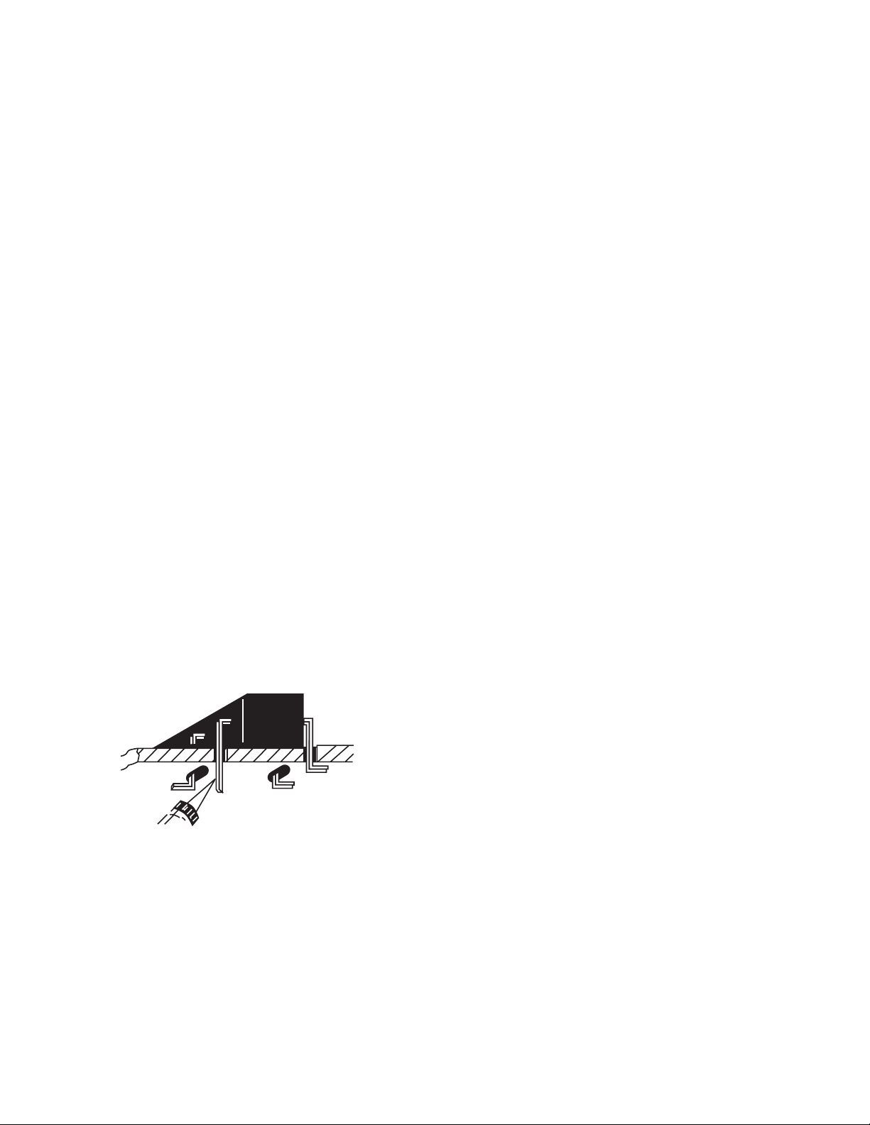
How to Replace Flat-lC
—Required Tools—
• Soldering iron • iron wire or small awl
• De-solder braids • Magnifier
1. Remove the solder from all of the pins of a Flat-lC by
using a de-solder braid.
2. Put the iron wire under the pins of the Flat-lC and pull it
in the direction indicated while heating the pins using a
soldering iron. A small awl can be used instead of the
iron wire.
3. Remove the solder from all of the pads of the FlatlC by using
a de-solder braid.
4. Position the new Flat-lC in place (apply the pins of the
Flat-lC to the soldering pads where the pins need to be
soldered). Properly determine the
positions of the soldering pads
and pins by correctly aligning the
polarity symbol.
6. Check with a magnifier for solder bridge between the
pins or for dry joint between pins and soldering pads. To
remove a solder bridge, use a de-solder braid as shown
in the figure below.
NOTE:
These components are affixed with glue. Be careful not to break or damage any foil under the
component or at the pins of the ICs when removing. Usually applying heat to the component for a short
time while twisting with tweezers will break the component loose.
Chip Components
TYPE
GRADE
C
B
E
SOLDER
CAPS
TRANSISTOR
CAPACITOR
1ST DIGIT
2ND DIGIT
MULTIPLIER
= 1600 = 1.6K
ANODES
MH DIODE
RESISTOR
SOLDER CAPS
COMMON CATHODE
De-Solder
Braid
Soldering
Iron
Soldering
Iron
Soldering
Iron
Soldering
Iron
Soldering
Iron
Soldering
Iron
De-Solder
Braid
Flat-IC
Bridge
Solder
De-Solder
Braid
Iron
Wire
Pull
Awl
Polarity Symbol
5. Solder all pins to the soldering pads using a fine tipped
soldering iron.

8
USEFUL INFO
AGENCY REGULATORY
INFORMATION
Federal Communications Commission Notice
This equipment has been tested and found to comply with the limits for a Class B digital device, pursuant to Part 15 of
the FCC Rules. These limits are designed to provide reasonable protection against harmful interference in a residential installation. This equipment generates, uses and can radiate radio frequency energy and if not installed and used
in accordance with the instructions, may cause harmful interference to radio communications. However, there is no
guarantee that interference will not occur in a particular installation. If this equipment does cause harmful interference
to radio or television reception, which can be determined by turning the equipment off and on, the user is encouraged
to try to correct the interference by one or more of the following measures:
¥ Reorient or relocate the receiving antenna.
¥ Increase the separation between the equipment and the receiver.
¥ Connect the equipment into an outlet on a circuit different from that to which the receiver is connected.
¥ Consult the dealer or an experienced radio/television technician for help.
Modifications
The FCC requires the user to be notified that any changes or modifications made to this device that are not expressly approved by Hitachi Home Electronics (America), Inc. may void the userÕs warranty.
Cables
Connections to this device must be made with shielded cables with metallic RFI/EMI connector hoods to maintain compliance with FCC Rules and Regulations.
Any cables that are supplied with the system must be replaced with identical cables in order to assure compliance with
FCC rules. Order Hitachi spares as replacement cables.
Declaration of Conformity
This device complies with Part 15 of the FCC Rules. Operation is subject to the following two conditions: (1) this device
may not cause harmful interference and (2) this device must accept any interference received, including interference
that may cause undesired operation.
Any cables that are supplied with the system must be replaced with identical cables in order to assure compliance with
FCC rules. Order Hitachi spares as replacement cables.
For questions regarding this declaration, contact:
Hitachi America, LTD.
Home Electronics Division
1855 Dornoch Court
San Diego, CA 92154
Tel. 1-800-448-2244 (1-800-HITACHI)
ATTN: CUSTOMER RELATIONS
9
SPECIFICATION
Features:
¥ Superfine Picture Quality with Digital Light ProcessingTMTechnology.
¥ Digital Micromirror DeviceTMSystem
* Digital Light Processing, DLP, Digital Micromirror Device and DMD are trademarks of Texas Instruments.
¥ 16:9 Aspect Ratio, 1280 x 720 Resolution
¥ HDTV compatible (1080i, 720P, 480P, 480i)
¥ PC input: XGA Compatible (XGA: Compressed, SVGA/VGA: Real)
¥ Perfect Picture System
¥ Remote (controls many VCR brands, cable box, satellite boxes and other audio equipment.)
¥ High Definition On Screen Display (Ultra TEC BIT-MAP)
¥ 2-Tuner Picture in Picture (Single, Split-Screen and Surf 3)
¥ Full Set of Input Jacks, including S-VIDEO
¥ COMPONENT: Y-CB/CRand Y-PB/PRInput Jacks
¥ 2 sets of PC input D-Sub Mini 15 pin connector
¥ Closed Caption Decoder
¥ Parental Control
¥ Dual Antenna inputs
¥ Digital 3 Dimensional Y/C Comb Filter (3DYC)
¥ All time progressive scanning with Multi-Scan Converter Technology
¥ Dolby Digital, Dolby Pro Logic, Stadium, Rock Arena, Jazz Club Surround Sound
* Manufactured under license from Dolby Laboratories. ÒDolbyÓ, ÒPro LogicÓ and the double-D symbol are trademarks of Dolby
Laboratories. Confidential Unpublished Works. ©1992-1997 Dolby Laboratories, Inc. All rights reserved.
I
nputs:
¥
Power Input . . . . . . . . . . . . .AC 120V, 60Hz
¥ Power Consumption (operating)
55DMX01W . . . . . . . . . . . . . . . . . . . .360W
¥ Power Consumption (maximum)
55DMX01W . . . . . . . . . . . . . . . . . . . .440W
¥ Antenna input impedance . . . . . . . . .75 Ohm
¥ Channel coverage . . . . . . . . . . . . . . .181ch.
VHF-Band . . . . . . . . . . . . . . . . . . . . .2 ~ 13
UHF-Band . . . . . . . . . . . . . . . . . . . .14 ~ 69
CATV Mid Band . . . . . . . . . . . . . . .A-5 ~ A-1
. . . . . . . . . . . . . . . . . . . . . . . . . . .A-I
Super Band . . . . . . . . . . . . . . . . . . . . .J-W
Hyper Band . . . . . . . . . . . . . . .W+1 - W+28
Ultra Band . . . . . . . . . . . . . . .W+29 - W+84
¥ Video . . . . . . . . . . . . . . . .1.0Vp-p, 75 Ohm
¥ S-VIDEO
Luminance (Y) . . . . . . . . . .1.0Vp-p, 75 Ohm
Chrominance (C) . . . . . .0.286Vp-p, 75 Ohm
¥ Component Video
Luminance (Y) . . . . . . . . . . . . . . .1.0Vp-p, 75 Ohm
Chrominance (CB,CR) . . . . . . . . .0.7Vp-p, 75 Ohm
Chrominance (PB,PR) . . . . . . . . .0.7Vp-p, 75 Ohm
¥ Audio input level(average) 470mVrms, 47k Ohm
Outputs:
¥ Video . . . . . . . . . . . . . . . . . . . . .1.0Vp-p. 75 Ohm
¥ Audio . . . . . . . . . . . . . . . . . . .470mVrms, 1k Ohm
¥ Rear Audio Speaker
Dimensions: 55DMX01W
¥ Height (in.) 40 1/16Ó
¥ Width (in.) 51 1/2Ó
¥ Depth (in.) 23 25/32Ó
¥ Weight (lbs.) 207 lbs.
NOTE: Due to improvements, specifications in this oper-
ating guide are subject to change without notice.
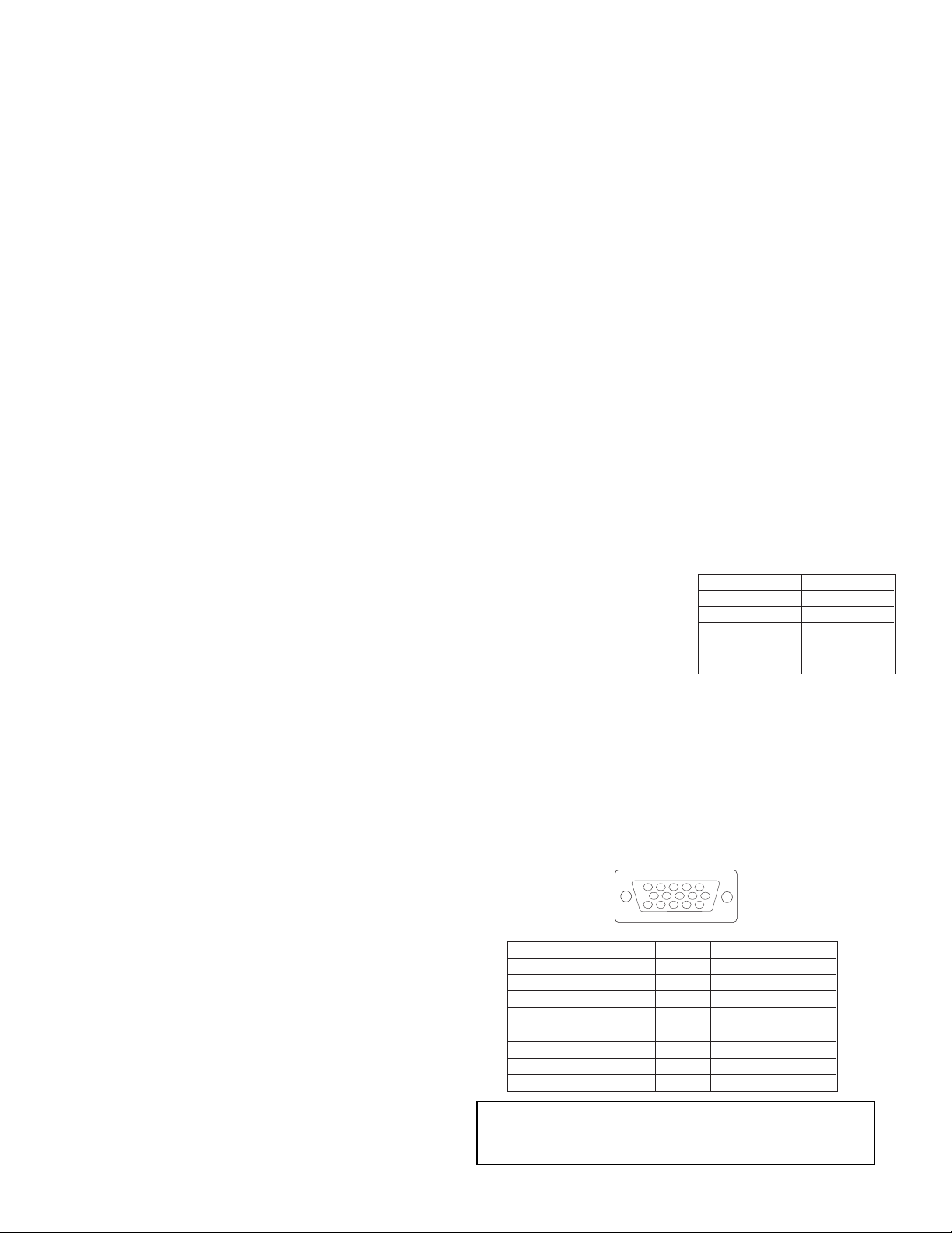
PIN NO. SIGNAL PIN NO. SIGNAL
1 Red Video 9 No Connection
2 Green Video 10 Ground
3 Blue Video 11 No Connection
4 No Connection 12 SDA (DDC)
5 No Connection 13 H-Sync
6 Red Ground 14 V-Sync
7 Green Ground 15 SCL (DDC)
8 Blue Ground
12345
678910
1112131415
D-Sub Mini 15-Pin connector Pin Assignments
CHANNEL THD=10% (8½)
FRONT L/R 12W+12W
CENTER 15W
REAR L/R W/
EXT. TERMINAL 12W+12W
TOTAL 60W
10
PLUG and PLAY
This DLPTMRear Projection TV complies with VESA DDC2B specifications,
Plug & Play is a system with computer, peripherals (including monitors) and
operating system. It works when the monitor is connected to a DDC ready
computer that is running an operating system software that is capable for the
plug & play.
When a Plug and Play PC is powered on, it sends a command to the Monitor
requesting identification. The Monitor sends back a string of data including its
characteristics.
TRADEMARK ACKNOWLEDGMENT
DDC is a trademark of Video Electronics Standard Association.
IBM PC/AT and VGA are registered trademarkds of International Business Machines Corporation of the U.S.A.
Apple and Macintosh are registered trademarks of Apple Computer, Inc.
VESA is a trademark of a nonprofit organization, Video Electronics Standard Association.
This Class B digital apparatus meets all requirements of the Canadian Interference-Causing Equipment Regulations.
This Class B digital apparatus complies with Canadian ICES-003.
Cet appareil numŽrique de la classe B ˆ la norme NMB-003 du Canada.
Cable Compatible Television Apparatus- T•l•vision c‰blocompatible, Canada.
Notes on Closed Caption:
This television receiver will display television closed captioning, ( or ), in accordance with paragraph 15.119
of the FCC rules.
TM
DLP is a trademark of Texas Instruments.

11
TABLE OF CONTENTS
I. Features and Functions
1.0 Front Control Panel ..........................................................................................................................................................12
2.0 Rear Panel Jacks ..............................................................................................................................................................15
3.0 Lamp Replacement............................................................................................................................................................19
4.0 TV Mode Ultratec OSD Features ......................................................................................................................................23
4.1 Set-Up ..........................................................................................................................................................................24
4.2 Customize ....................................................................................................................................................................27
4.3 Video ............................................................................................................................................................................28
5.0 PC Mode Ultratec OSD Feature........................................................................................................................................30
5.1 PC Mode Connection and Operation ..........................................................................................................................31
5.2 PC On-Screen Display ................................................................................................................................................33
6.0 PC/Component Input Signal Timing Specification ............................................................................................................37
7.0 Heat run ............................................................................................................................................................................46
7.1 LED Indicator................................................................................................................................................................46
8.0 Display Format of Component Video Terminal ..................................................................................................................47
II. Assembled PWB Adjustment ..................................................................................................................................................50
1.0 Memory Initialization ..........................................................................................................................................................50
2.0 I
2
C Parameter List..............................................................................................................................................................51
2.1 DLP
TM
Menu ..................................................................................................................................................................60
2.2 MSC Menu....................................................................................................................................................................62
2.3 FC Menu ......................................................................................................................................................................68
2.4 TA1298 Menu ..............................................................................................................................................................75
2.5 TA1270-1 Menu ............................................................................................................................................................78
2.6 TA1280-2 Menu ............................................................................................................................................................78
2.7 3D YC Menu ................................................................................................................................................................78
2.8 3L YC Menu..................................................................................................................................................................79
2.9 TA1318-1 Menu ............................................................................................................................................................79
2.10 TA1318-2 Menu ..........................................................................................................................................................79
2.11 Optical Engine Repair/Replaceable Parts ..................................................................................................................80
3.0 Raster Position Adjustment ..............................................................................................................................................81
3.1 Prework ........................................................................................................................................................................81
3.1.1 Raster Position Adjustment Flow Chart ..................................................................................................................82
3.2 Afterwork ......................................................................................................................................................................84
3.3 Adjustment Method ......................................................................................................................................................85
3.3.1 Tilt Adjustment ........................................................................................................................................................86
3.3.2 Trapezoid Adjustment (TOP/BOTTOM) ..................................................................................................................88
3.3.3 Trapezoid Adjustment (LEFT/RIGHT) ....................................................................................................................90
3.3.4 Horizontal Position Adjustment................................................................................................................................91
3.3.5 Vertical Position Adjustment....................................................................................................................................92
4.0 Display Area Specification................................................................................................................................................93
4.1 Raster Distortion Check................................................................................................................................................94
4.2 Lens Focus Adjustment ................................................................................................................................................94
4.2.1 Adjustment Preparation ..........................................................................................................................................94
4.2.2 Lens Focus Performance Check ............................................................................................................................94
4.2.3 Lens Focus Re-adjustment Procedure....................................................................................................................95
5.0 Comb Filter Operation Check ............................................................................................................................................97
6.0 Power Supply Protection Circuit Operation Check............................................................................................................98
6.1 Power Supply Voltage Check ......................................................................................................................................98
6.2 Power Supply Block Diagram ......................................................................................................................................98
6.3 Explanation of Power Supply Block Diagram ..............................................................................................................99
7.0 RGB Brightness Level Adjustment ..................................................................................................................................100
8.0 Brightness Adjustment ....................................................................................................................................................102
9.0 Sub-Contrast Adjustment ................................................................................................................................................102
10.0 White Balance Adjustment ............................................................................................................................................103
11.0 PIP Picture Adjustment ..................................................................................................................................................104
12.0 Door Protection Operation Check..................................................................................................................................105
13.0 High Temperature Protection Operation Check ............................................................................................................105
14.0 Color Wheel Protection Operation Check ....................................................................................................................106
15.0 Color Termperature Control Check ................................................................................................................................106
16.0 User Control Initialize (Factory Reset Condition) ..........................................................................................................107
17.0 Adjustment Point Locations............................................................................................................................................110
18.0 Protection Circuit Diagram ............................................................................................................................................114
19.0 Trouble Shooting Flow Charts ......................................................................................................................................115
12
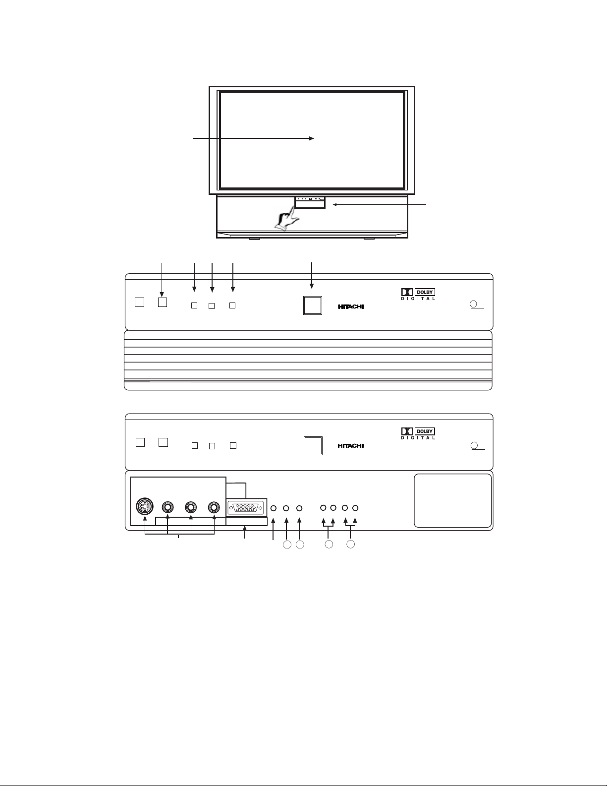
I. FEATURES AND FUNCTIONS
1.0 FRONT PANEL CONTROLS
햲
REMOTE CONTROL Sensor
Point your remote at the screen when selecting channels, adjusting volume, etc. The remote control sensor is inside the screen.
햳 PERFECT PICTURE Sensor
The PERFECT PICTURE sensor will make automatic picture adjustments depending on the amount of light in the room to give the
best picture.
햴 LAMP Indicator - NORMAL OPERATION INDICATOR IS OFF
If light is lit, the lamp has failed. See lamp replacement procedure. If light is blinking, lamp cover is not assembled securely after
replacement.
햵 TEMP Indicator
This light is off during normal operation.
If this indicator is lit, the optic unit is too hot. If this indicator is blinking, the cooling fan has stopped. Please call service.
Shown with Control
Panel Door Closed.
LAMP
TEMP
POWER
Push to open door for
front controls and inputs.
DLP
A TEXAS INSTRUMENTS TECHNOLOGY
왗
INPUT 3
VOL-
왗
왗
10
Shown with Control
Panel Door Open.
LAMP
TEMP
POWER
AUDIO/
PC AUDIO
L/(MONO) R
VIDEO
S-VIDEO
INPUT 2
PC RGB INPUT 2
12345
678910
1112131415
INPUT
VOL+
CH- CH+
TV/PC
EXIT
MENU
왘
11
1312
SELECT
PUSH
POWER
DLP
A TEXAS INSTRUMENTS TECHNOLOGY
PUSH
POWER
FRONT VIEW
13
햶 POWER Light
This light is on during normal operation.
Light Blinking Slowly (2 seconds): Rear Projection Television lamp is cooling down. It takes 12-15 seconds to warm up and
about 2 minutes to cool down.
햷 POWER Button
Press this button to turn the TV on or off.
햸 FRONT INPUT JACKS (for VIDEO: 3 and PC2 AUDIO)
Use these audio/video jacks for a quick hook-up from a camcorder or VCR to instantly view your favorite show or new recording.
Press the INPUT button until VIDEO: 3 appears in the top right corner of the TV screen. If you have mono sound, insert the audio
cable into the left audio jack. VIDEO: 3 audio input jacks can be used for PC2 audio when a PC is connected to front input VIDEO:
3 jack.
햹 PC INPUT 2 (Front)
Use this 15 pin D-Sub input for a ÒquickÓ hook up from your PC connection.
햺 TV/PC Button
Press this button to switch from TV, PC INPUT 1 (PC1) and PC INPUT 2 (PC2). Your selection is shown in the top right corner of
the screen.
햻 INPUT/EXIT Button
Press this button to select the current antenna source, VIDEO: 1, 2, 3 or alternate antenna source. Your selection is shown in the
top right corner of the screen. This button also serves as the EXIT button when in MENU mode.
햽 MENU Button
This button allows you to enter the MENU, making it possible to set TV features to your preference without using the remote.
This button also serves as the SELECT button when in menu mode.
햾 VOLUME Level
Press these buttons for your desired sound level. The volume level will be displayed on the TV screen. These buttons also serve
as the cursor left (씱) and right (씰) buttons when in MENU mode.
햿 CHANNEL Selector
Press these buttons until the desired channel appears in the top right corner of the TV screen. These buttons also serve as the
cursor down (쑼) and up (쑿) buttons when in MENU mode.
NOTE: COMPONENT INPUT takes priority over S-VIDEO input, and S-VIDEO input takes priority over VIDEO input.
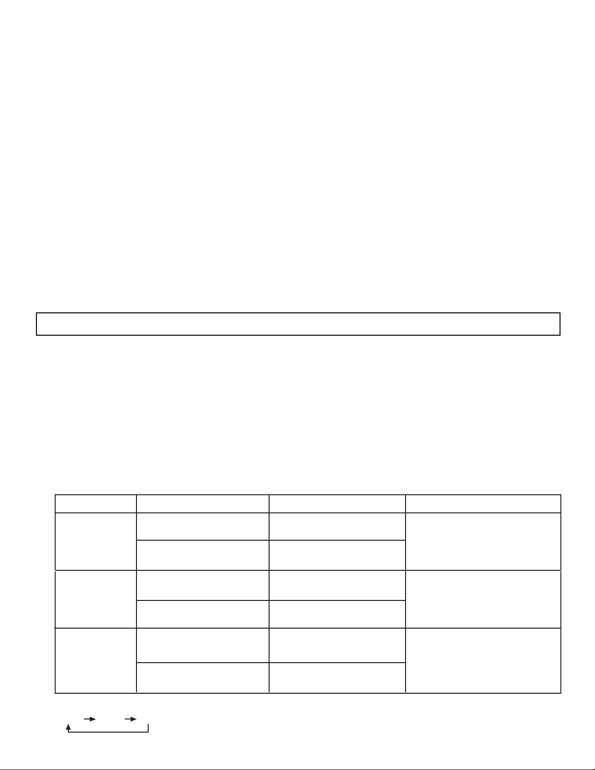
NO LAMP LIGHT
or BROKEN LAMP
WRONG LAMP UNIT
ASSEMBLY
Too Hot inside the
OPTIC unit
COOLING FAN STOPPED
NORMAL
OPERATION
COOL DOWN
LIGHT ON
BLINKING
LIGHT ON
BLINKING
LIGHT ON
SLOWLY BLINKING
INDICATOR INDICATION MEANING ACTION
LAMP LED
TEMP
LED
POWER
Need to exchange if
LAMP still does not light by
ÒPower OnÓ again.
Check assembly condition of
LAMP UNIT
Call Service
NOTES:
1.
2. If the LAMP, TEMP, and POWER LED are blinking in the order below, the Rear Projection Television is warming up.
LAMP TEMP POWER
I. FEATURES AND FUNCTIONS
1.0 FRONT PANEL CONTROLS (CONT.)
14
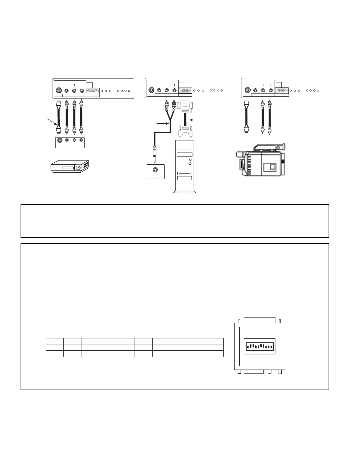
NOTE: Optional adapter for *Apple®Macintosh®computers. If the optional AESP model G301/U Macintosh to VGA®adapter
connector is configured and connected between Macintosh video out and the Rear Projection Television video in, the
Macintosh is ÒforcedÓ to boot in 640 x 480/60 Hz or 800 x 600/60 Hz mode (set mode) because the operational adapter
correctly manipulates the Macintosh sense pins.
For the optional adapter to work, itÕs DIP switch settings should be # 2, 3, 6, 7 = ON and # 1, 4, 5, 8, 9, 10 = OFF.
See below: Example - See Switch Instructions for details.
Mode 5 = 2367 (SVGA 800 x 600/60 Hz configuration)
(VGA 640 x480/60 Hz configuration)
Composite Separate Sync
ON
DIP
1
2
34567
8910
ON
1
458910
2
367
OFF
SW1 SW2 SW3 SW4 SW5 SW6 SW7 SW8 SW9 SW10
ON ON ON ON
OFF OFF OFF OFF OFF OFF
A/V Cable and
S-INPUT Cable
(Optional)
Back of VCR
V L R
S-VIDEO
OUTPUT
D-SUB 15 Pin
RGB Cable
(Optional)
PC
AUDIO OUT
Back of PC
Audio Cable
(Optional)
S-VHS Video Camera Output
NOTE: Completely insert connection cord plugs when connecting to front panel jacks. If you do not, the played back picture may
be abnormal. If you have an S-VHS VCR, use the S-INPUT cable in place of the standard video cable. If you have a
mono VCR, insert the audio cable into the left audio jack of your TV. INPUT 3 audio can be used for PC INPUT 2 audio
when a PC INPUT 2 is connected.
The front panel jacks are provided as a convenience to allow you to easily connect a VCR, PC or camcorder as shown in the following examples:
I. FEATURES AND FUNCTIONS
1.0 FRONT PANEL CONTROLS (CONT.)
S-VIDEO
AUDIO/
INPUT 2
PC AUDIO
VIDEO
L/(MONO) R
INPUT 3
PC RGB INPUT 2
12345
678910
1112131415
VOL-
CH- CH+
MENU
INPUT
VOL+
SELECT
TV/PC
EXIT
왗
왗
왘
왗
S-VIDEO
AUDIO/
INPUT 2
PC AUDIO
VIDEO
L/(MONO) R
INPUT 3
12345
1112131415
PC RGB INPUT 2
678910
VOL-
CH- CH+
MENU
INPUT
VOL+
SELECT
TV/PC
EXIT
왗
왗
왘
왗
S-VIDEO
AUDIO/
INPUT 2
PC AUDIO
VIDEO
L/(MONO) R
INPUT 3
12345
1112131415
PC RGB INPUT 2
678910
VOL-
CH- CH+
MENU
INPUT
VOL+
SELECT
TV/PC
EXIT
왗
왗
왘
왗
15
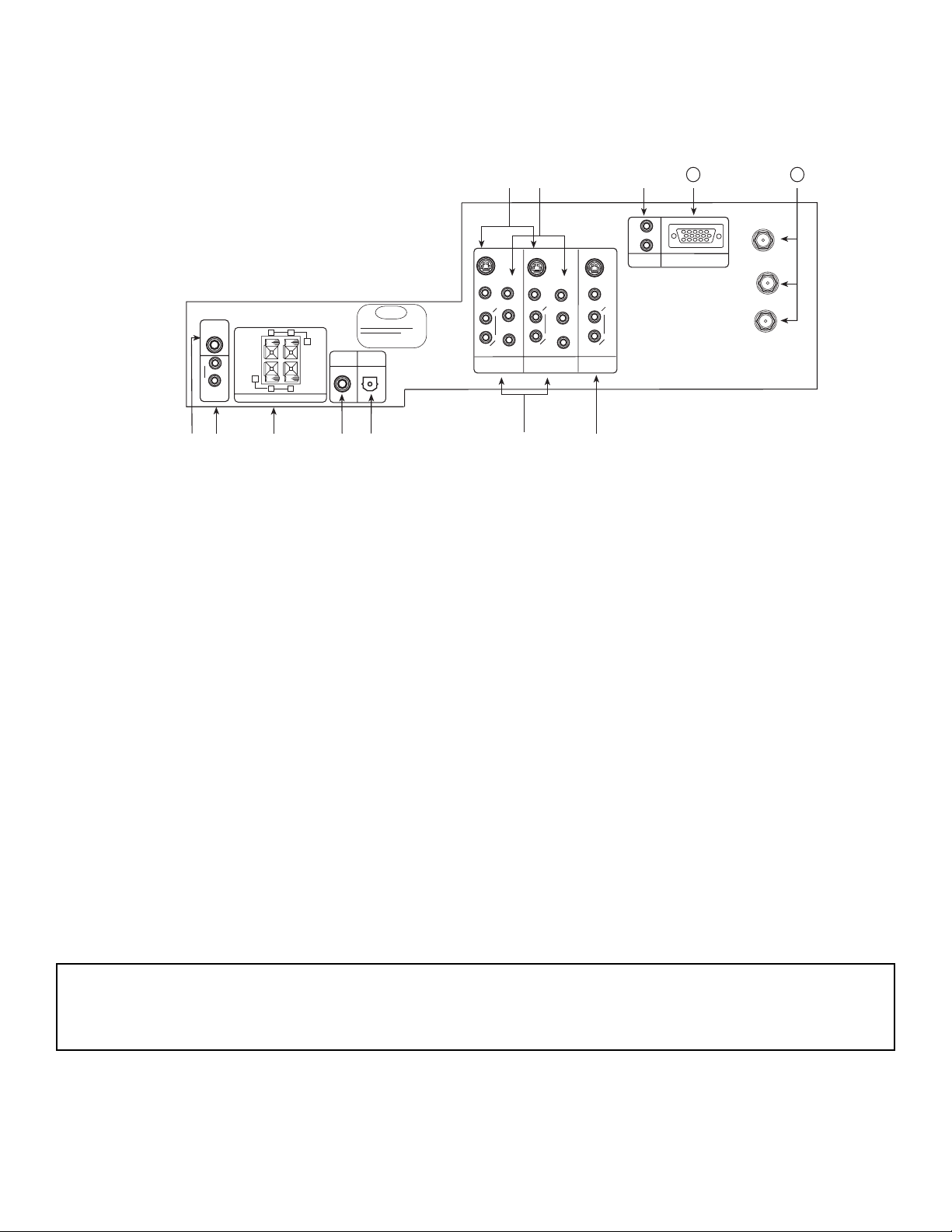
REAR VIEW
햲 SUB WOOFER Output
This jack provides variable audio output to a sub-woofer accessory. With this connection, the audio can be controlled by the
televisionÕs main volume. This feature can be turned on and off in the THEATER-SPEAKER SETUP menu.
햳 AUDIO TO Hi-Fi
These jacks provide variable audio output to a seperate stereo amplifier. With this connection, the audio to the stereo can be controlled by the televisionÕs main volume. Use these jacks for the external audio amplifier.
햴 REAR SPEAKER Output Terminals
These terminals are used to connect external speakers, which are used for the surround sound feature. The volume level is
controlled by the televisionÕs main volume. These speaker output terminals can be turned on and off in the THEATER-SPEAKER
SETUP menu. Use speakers with 8-Ohm impedance only.
햵 Coaxial Input
This jack provides high quality audio input from a Dolby Digital DVD player or HDTV Set Top Box. This input can be used for
VIDEO: 1 or VIDEO: 2 audio, as selected in the THEATER-INPUT SOURCE menu.
햶 Optical Input
This jack provides high quality audio input from a Dolby Digital DVD player or HDTV Set Top Box. Use a digital optical cable to
connect your TV to a compatible device. This input can be used for VIDEO: 1 or VIDEO: 2 audio, as selected in the THEATERINPUT SOURCE menu.
ANT A
TO
CONVERTER
ANT B
12345
678910
1112131415
햹햸햺
햻
AUDIO
L
R
(MONO)
VIDEO
VIDEO
AUDIO
(MONO)
L
R
AUDIO
(MONO)
L
R
VIDEO
S-VIDEO
Y
S-VIDEO
Y
B
R
P
P
B
R
P
P
S-VIDEO
햷
L
R
L
R
SUB
WOOFER
STOP
CONNECT ONLY 8 OHM SPEAKERS
DO NOT SHORT CIRCUIT
THESE TERMINALS
(Such damage is NOT COVERED
by your television warranty)
11
12
REAR SPEAKER
8Ω ONLY
L
+
-
+
R
OPTICAL
INPUT
COAXIAL
INPUT
햲
햴
햳
햵
햶
PC RGB INPUT 1
PC AUDIO
INPUT 1
MONITOR
OUT
INPUT 2
INPUT 1
AUDIO
TO HI-FI
NOTE: This TVÕs optical digital input jack fully complies with the international standard governing this type of jack (IEC958), and
is designed for connection to a Dolby Digital or PCM from DVD Player or HDTV Set Top Box. Older equipment, some of
which is not fully compliant with IEC958, may not be compatible with the Dolby Digital bit stream. Such a connection
using anything other than Dolby Digital AC-3 or PCM bit stream could create a high noise level, causing damage to your
speakers.
I. FEATURES AND FUNCTIONS
2.0 REAR PANEL JACKS

16
햷 AUDIO/VIDEO INPUTS 1, 2
The INPUT button on the front panel or Remote Control will step through each signal source input each time it is pressed. Use
the audio and video inputs to connect external devices, such as VCRs, camcorders, laserdisc players, DVD players etc. (If you
have mono sound, insert the audio cable into the left audio jack.)
MONITOR OUT
These jacks provide fixed audio and video signals which are used for recording. Use the S-VIDEO Output for high quality video
output. There is no MONITOR OUT when using COMPONENT VIDEO INPUT.
S-VIDEO Inputs 1 and 2
Inputs 1 and 2 provide S-VIDEO (Super Video) jacks for connecting equipment with S-VIDEO output capability.
햺 COMPONENT VIDEO Y-P
BPR
INPUT
Y-PBPRjacks provide for connecting equipment with this capability, such as a DVD player.
햻 PC AUDIO INPUT 1
Connect external devices for audio in PC mode.
햽 PC INPUT 1
Use this 15-pin D-Sub Input for your PC connection.
햾 ANTENNA Input/Output
The remote control allows you to switch between two separate 75-Ohm RF antenna inputs, ANT A and ANT B. ANT A input can be
displayed as a main picture or sub-picture. ANT B can only be displayed as a main picture. (ANT B cannot be displayed as a subpicture.) The antenna output labeled ÒTO CONVERTERÓ allows the ANT A connection to pass directly to a different source, such
as a cable box, only when ANT B is displayed as a main picture.
NOTE: DO NOT connect standard VIDEO or S-VIDEO when using Y-PBPRinput.
Your component outputs may be labeled Y, B-Y, and R-Y. In this case, connect the components B-Y output to the TVÕs
PBinput and the components R-Y output to the TVÕs PRinput.
It may be necessary to adjust TINT or turn AUTO COLOR-ON to obtain optimum picture quality when using the
Y-PBPR inputs.
To ensure no copyright infringement, the MONITOR OUT output will be abnormal, when using the Y-PBPRjacks.
When using the Y-PBPRjacks, Component Y-PBPRsignal will be viewed as a blank PIP sub-picture.
NOTE: S-VIDEO Output may be used for recording, only when the input is of S-VIDEO type.
NOTE: You may use VIDEO, S-VIDEO, or COMPONENT: Y-PBPRInputs to connect to INPUT 1, 2. But note that only one of
these may be used at a time.
COMPONENT INPUT takes priority over S-VIDEO input and S-VIDEO input takes priority over VIDEO input.
I. FEATURES AND FUNCTIONS
2.0 REAR PANEL JACKS (CONT.)

17
TIPS ON REAR PANEL CONNECTIONS
S-VIDEO connections are provided for high performance laserdisc players, VCRs etc. that have this feature. Use these connections in place of the standard video connection if your device has this feature.
If your device has only one audio output (mono sound), connect it to the left audio jack on the television.
Refer to the operating guide of your other electronic equipment for additional information on connecting your hook-up cables.
A single VCR can be used for VCR#1 and VCR#2, but note that a VCR cannot record its own video or line output. Refer to your
VCR operating guide for more information on line input-output connection.
You may use VIDEO, S-VIDEO, or COMPONENT: Y-PBPRinputs, but note that only one of these may be used at a time.
Connect only 1 component to each input jack.
COMPONENT: Y-PBPR connections are provided for high performance components, such as DVD players. Use these connections in place of the standard video connection if your device has this feature.
When using the Y-PBPRinput jacks, connect your components audio output to the TVÕs Left and Right audio input jacks.
Your component outputs may be labeled Y, B-Y, and R-Y. In this case, connect the components B-Y output to the TVÕs PBinput and
the components R-Y output to the TVÕs PRinput.
It may be necessary to adjust TINT or turn AUTO COLOR-ON to obtain optimum picture quality when using the
Y-PBPRinputs.
To ensure no copyright infringement, the MONITOR OUT output will be abnormal, when using the
Y-PBP
R
jacks.
NOTE: Turn off the Rear Projection Television and the PC before connecting or disconnecting any cables.
I. FEATURES AND FUNCTIONS
2.0 REAR PANEL JACKS (CONT.)

18
ANT A
TO
CONVERTER
ANT B
12345
678910
1112131415
AUDIO
L
R
(MONO)
VIDEO
VIDEO
AUDIO
(MONO)
L
R
AUDIO
(MONO)
L
R
VIDEO
S-VIDEO
Y
S-VIDEO
Y
B
R
P
P
B
R
P
P
S-VIDEO
L
R
L
R
SUB
WOOFER
STOP
CONNECT ONLY 8 OHM SPEAKERS
DO NOT SHORT CIRCUIT
THESE TERMINALS
(Such damage is NOT COVERED
by your television warranty)
REAR SPEAKER
8Ω ONLY
L
+
-
+
R
OPTICAL
INPUT
COAXIAL
INPUT
PC RGB INPUT 1
PC AUDIO
INPUT 1
MONITOR
OUT
INPUT 2
INPUT 1
AUDIO
TO HI-FI
2-Way signal splitter
Outside antenna or
cable TV coaxial cable
12345
678910
1112131415
AUDIO OUT
OPTIONAL
VCR #2
V L R
INPUT
S-VIDEO
INPUT
OUTPUT
Cable TV Box
OPTIONAL
OPTIONAL
DVD Player
VCR #1
ANT
IN
OUTPUT
S-VIDEO
VL R
OUTPUT
YP
B/CBPR/CR
L R
OR
RGB
OUTPUT
Stereo System
Amplifier
Surround Speakers
+
-
+
-
LR
L
R
INPUT
Sub Woofer
INPUT
Laserdisc player, VCR,
camcorder, etc.
OUTPUT
Y P
B
P
R
L R
HDTV Set-Top Box
V L R
OUTPUT
S-VIDEO
OR
NOTES: 1. Connect only 1 component to each input jack.
2. Follow connections that pertain to your personal entertainment system.
TYPICAL FULL-FEATURE SETUP
I. FEATURES AND FUNCTIONS
2.0 REAR PANEL JACKS (CONT.)

19
Lamp Replacement
After extended use, if the TV picture turns dark, the color looks unusual or LAMP INDICATOR light
turns on, then it is time to replace the lamp with a new lamp. Lamp should be replaced after 4,000
hours of use.
WARNING:
The lamp gets very hot! The lamp may explode if improperly handled. To avoid injury, please observe the following
precautions.
¥ Do not open lamp compartment or attempt to remove lamp assembly unless the lamp assembly is being replaced.
¥ Unplug the productÕs power cord from the AC outlet before attempting to replace the lamp assembly.
¥ If the lamp is in use when failure occurs or if the lamp has exploded, wait at least 30-45 minutes for the lamp to
cool before opening the lamp compartment or touching the lamp assembly or any broken pieces.
¥ Broken lamp pieces can cause injury. Handle with gloves to avoid cuts.
¥ Do not place any foreign objects inside the lamp compartment.
¥ When installing a new lamp, follow handling instruction included with the new lamp. Do not touch glass surface of
new lamp.
¥ Please dispose of old lamp assembly properly.
CAUTION!
A ÓLAMPÓ indicator will light when lamp becomes hot. Unplug productÕs power cord from the AC outlet and allow
lamp to cool for at least 30-45 minutes.
NOTES:
¥ Contact your Hitachi dealer for a new lamp unit. Using other lamps may cause damage to
the TV Set.
TYPE NAME: DLPTMLAMP ASSEMBLY
PART NUMBER: DP00341
¥ When replacing the lamp, let it cool down completely, for approximately 30 to 45 minutes
after the power has been switched off and A.C. cord has been unplugged.
¥ Do not touch the glass of the new lamp or make it dirty which can shorten the life
of the lamp and ruin the picture quality.
¥ Keep the lamp out of the reach of children and away from flammable materials.
¥ Do not pour water onto the removed lamp or put any object inside the lamp.
¥ Once the lamp is removed, do not put flammable materials and metal objects inside the
lamp receptacle on the TV set. Do not touch the receptacle.
¥ Install the new lamp securely, otherwise the picture may become dark or it may cause
severe overheating and possible fire.
¥ Install the lamp cover correctly, otherwise power will not come on.
¥ When you have finished changing the lamp, remember to reset the LAMP TIME COUNTER.
(See page 49 to reset the LAMP TIME COUNTER.)
¥ LAMP MUST BE DISPOSED OF PROPERLY. FOR ASSISTANCE, PLEASE CALL
1-800-HITACHI
I. FEATURES AND FUNCTIONS
3.0 LAMP REPLACEMENT
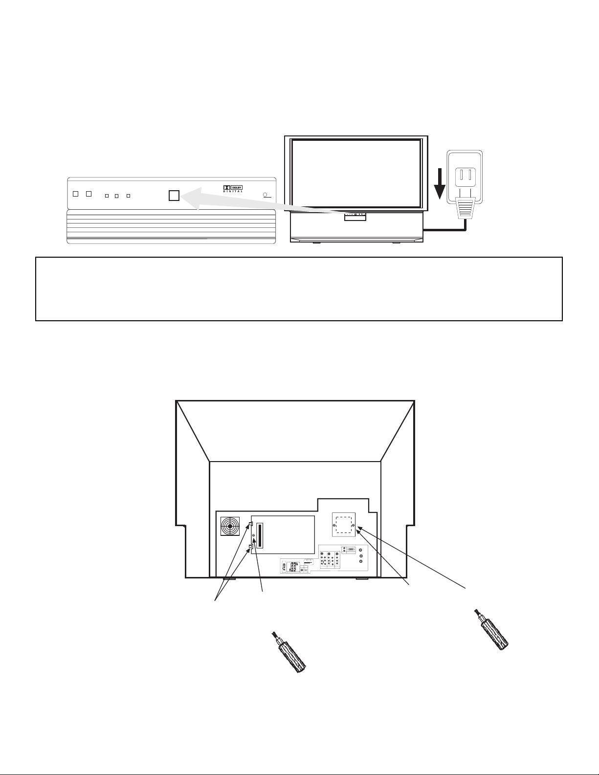
20
POWER
LAMP
TEMP
POWER
DLP
A TEXAS INSTRUMENTS TECHNOLOGY
PUSH
120V
PUSH
ANT A
✴✯
CONVERTER
✡✮✴ ✢
12345
678910
1112131415
✡✵✤✩✯
✬
✲
✈✭✯✮✯✉
✶✩✤✥✯
✶✩✤✥✯
✡✵✤✩✯
✈✭✯✮✯✉
✬
✲
✡✵✤✩✯
✈✭✯✮✯✉
✬
✲
✶✩✤✥✯
✳✍✶✩✤✥✯
✹
✳✍✶✩✤✥✯
✹
✢
✲
✣
✰
✢
✲
✣
✰
✳✍✶✩✤✥✯
✬
✲
✬
✲
✳✵✢
✷✯✯✦✥✲
STOP
CONNECT ONLY 8 OHM SPEAKERS
DO NOT SHORT CIRCUIT
THESE TERMINALS
(Such damage is NOT COVERED
by your television warranty)
✲✥✡✲ ✳✰✥✡✫✥✲
8Ω ONLY
✍
✬
☞
✍
☞
✲
✯✰✴✩✣✡✬
✩✮✰✵✴
✣✯✡✸✩✡✬
✩✮✰✵✴
✰✣ ✲✧✢ ✩✮✰✵✴ ✑
✰✣ ✡✵✤✩✯
✩✮✰✵✴ ✑
✭✯✮✩✴✯✲
✯✵✴
✩✮✰✵✴ ✒
✩✮✰✵✴ ✑
✡✵✤✩✯
✴✯ ★✩✍✦✩
Two Clips
Spare Lamp
Retaining
Screw
Lamp Cover
Retaining
Screw
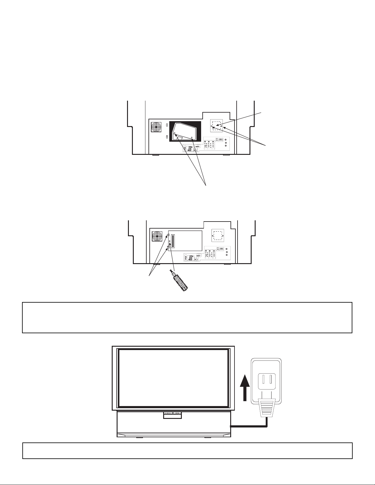
2. Loosen the screw that secures the lamp cover with a Phillips Head Screw Driver.
Release the two clips on the left side of lamp cover. Remove the lamp cover by pulling
it toward you and to the right.
1. Turn off the main power switch on the front panel and unplug the power cord from the wall
outlet.
CAUTION: THE LAMP IS VERY HOT AND MAY CAUSE FIRE OR SEVERE BURNS. WAIT AT
LEAST 30 MINUTES TO ALLOW THE LAMP TO COOL BEFORE PROCEEDING WITH
LAMP REMOVAL.
I. FEATURES AND FUNCTIONS
3.0 LAMP REPLACEMENT (CONT.)
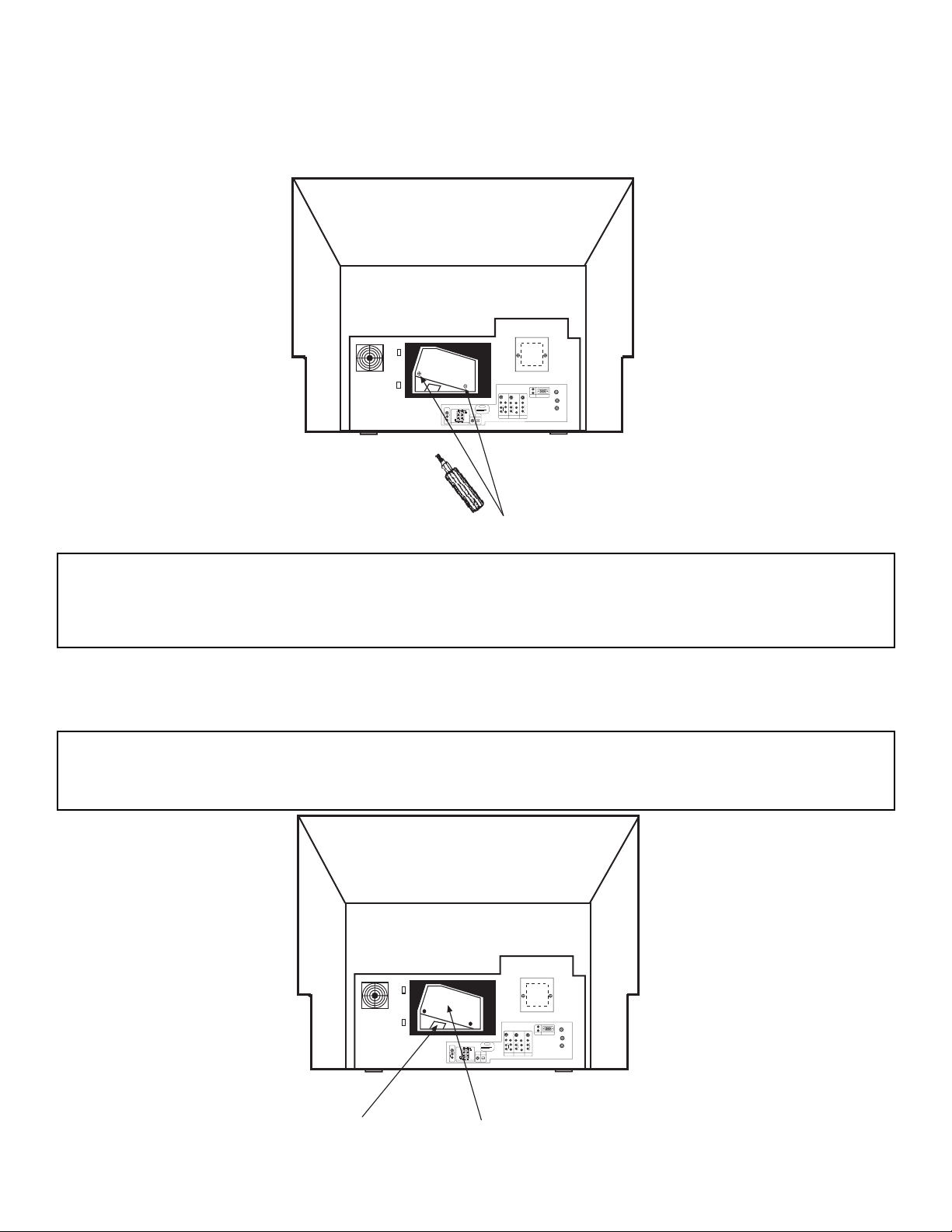
21
3. Loosen the two screws securing the latch cover with a Phillips Head Screw Driver as
shown. If these screws are not loosened completely, the lamp unit cannot be removed.
ANT A
✴✯
✣✯✮✶✥✲✴✥✲
✡✮✴ ✢
12345
678910
1112131415
✡✵✤✩✯
✬
✲
✈✭✯✮✯✉
✶✩✤✥✯
✶✩✤✥✯
✡✵✤✩✯
✈✭✯✮✯✉
✬
✲
✡✵✤✩✯
✈✭✯✮✯✉
✬
✲
✶✩✤✥✯
✳✍✶✩✤✥✯
✹
✳✍✶✩✤✥✯
✹
✢
✲
✣
✰
✢
✲
✣
✰
✳✍✶✩✤✥✯
✬
✲
✬
✲
✳✵✢
✷✯✯✦✥✲
STOP
CONNECT ONLY 8 OHM SPEAKERS
DO NOT SHORT CIRCUIT
THESE TERMINALS
(Such damage is NOT COVERED
by your television warranty)
✲✥✡✲ ✳✰✥✡✫✥✲
8Ω ONLY
✍
✬
☞
✍
☞
✲
✯✰✴✩✣✡✬
✩✮✰✵✴
✣✯✡✸✩✡✬
✩✮✰✵✴
✰✣ ✲✧✢ ✩✮✰✵✴ ✑
✰✣ ✡✵✤✩✯
✩✮✰✵✴ ✑
✭✯✮✩✴✯✲
✯✵✴
✩✮✰✵✴ ✒
✩✮✰✵✴ ✑
✡✵✤✩✯
✴✯ ★✩✍✦✩
Lamp Unit Retaining Screws
4. Remove the lamp unit by holding the lamp handle, then pulling outwards. Exercise caution when removing the lamp unit to avoid injury to your fingers. If the lamp unit does
not come out easily, check to make sure the screws in step 3 are loosened completely.
WARNING: DO NOT PUT YOUR HAND IN THE LAMP STORAGE AREA AFTER THE LAMP UNIT
IS REMOVED, YOU MAY GET BURNED.
ANT A
TO
CONVERTER
ANT B
12345
678910
1112131415
AUDIO
L
R
(MONO)
VIDEO
VIDEO
AUDIO
(MONO)
L
R
AUDIO
(MONO)
L
R
VIDEO
S-VIDEO
Y
S-VIDEO
Y
B
R
C
P
B
R
C
P
S-VIDEO
L
R
L
R
SUB
WOOFER
STOP
CONNECT ONLY 8 OHM SPEAKERS
DO NOT SHORT CIRCUIT
THESE TERMINALS
(Such damage is NOT COVERED
by your television warranty)
REAR SPEAKER
8Ω ONLY
L
+
-
+
R
OPTICAL
INPUT
COAXIAL
INPUT
PC RGB INPUT 1
PC AUDIO
INPUT 1
MONITOR
OUT
INPUT 2
INPUT 1
AUDIO
TO HI-FI
Handle
Lamp Unit
CAUTION: THE LAMP IS VERY HOT AND MAY CAUSE FIRE OR SEVERE BURNS. AFTER
UNPLUGGING THE POWER CORD, WAIT AT LEAST 30 MINUTES UNTIL THE LAMP
IS COOL BEFORE ATTEMPTING TO REMOVE.
I. FEATURES AND FUNCTIONS
3.0 LAMP REPLACEMENT (CONT.)
22
7. Reinstall the lamp cover by re-engaging the two clips and installing the screw removed
in Step 2. Be sure to install the lamp cover securely and tighten the screw before turning the power on, otherwise it may cause unusual colors.
ANT A
✴✯
✣✯✮✶✥✲✴✥✲
✡✮✴ ✢
12345
678910
1112131415
✡✵✤✩✯
✬
✲
✈✭✯✮✯✉
✶✩✤✥✯
✶✩✤✥✯
✡✵✤✩✯
✈✭✯✮✯✉
✬
✲
✡✵✤✩✯
✈✭✯✮✯✉
✬
✲
✶✩✤✥✯
✳✍✶✩✤✥✯
✹
✳✍✶✩✤✥✯
✹
✢
✲
✣
✰
✢
✲
✣
✰
✳✍✶✩✤✥✯
✬
✲
✬
✲
✳✵✢
✷✯✯✦✥✲
STOP
CONNECT ONLY 8 OHM SPEAKERS
DO NOT SHORT CIRCUIT
THESE TERMINALS
(Such damage is NOT COVERED
by your television warranty)
✲✥✡✲ ✳✰✥✡✫✥✲
8Ω ONLY
✍
✬
☞
✍
☞
✲
✯✰✴✩✣✡✬
✩✮✰✵✴
✣✯✡✸✩✡✬
✩✮✰✵✴
✰✣ ✲✧✢ ✩✮✰✵✴ ✑
✰✣ ✡✵✤✩✯
✩✮✰✵✴ ✑
✭✯✮✩✴✯✲
✯✵✴
✩✮✰✵✴ ✒
✩✮✰✵✴ ✑
✡✵✤✩✯
✴✯ ★✩✍✦✩
Lamp Cover Retaining Screw
Two Clips
8. Plug power cord into AC outlet and turn on the main power switch.
120V
PUSH
NOTES: 1. After installing the new lamp, donÕt forget to reset the LAMP TIME COUNTER.
2. The old lamp must be disposed of properly. For assistance, please call 1-800-HITACHI.
5. Remove the two screws securing the spare lamp unit. Remove the spare lamp unit.
Replace the spare lamp cover.
6. Replace the lamp.
¥ Push the lamp unit back to its original position.
¥ Tighten the screws firmly on the lamp unit. If they are loose, the TV may not operate
correctly.
ANT A
TO
CONVERTER
ANT B
12345
678910
1112131415
AUDIO
L
R
(MONO)
VIDEO
VIDEO
AUDIO
(MONO)
L
R
AUDIO
(MONO)
L
R
VIDEO
S-VIDEO
Y
S-VIDEO
Y
B
R
C
P
B
R
C
P
S-VIDEO
L
R
L
R
SUB
WOOFER
STOP
CONNECT ONLY 8 OHM SPEAKERS
DO NOT SHORT CIRCUIT
THESE TERMINALS
(Such damage is NOT COVERED
by your television warranty)
REAR SPEAKER
8Ω ONLY
L
+
-
+
R
OPTICAL
INPUT
COAXIAL
INPUT
PC RGB INPUT 1
PC AUDIO
INPUT 1
MONITOR
OUT
INPUT 2
INPUT 1
AUDIO
TO HI-FI
Lamp Unit Retaining Screws
Retaining Screws
Spare Lamp
CAUTION: IF POWER IS CONNECTED BEFORE THE LAMP COVER IS INSTALLED, THE
POWER WILL BE OFF AND THE LAMP INDICATOR WILL FLASH.
I. FEATURES AND FUNCTIONS
3.0 LAMP REPLACEMENT (CONT.)
23
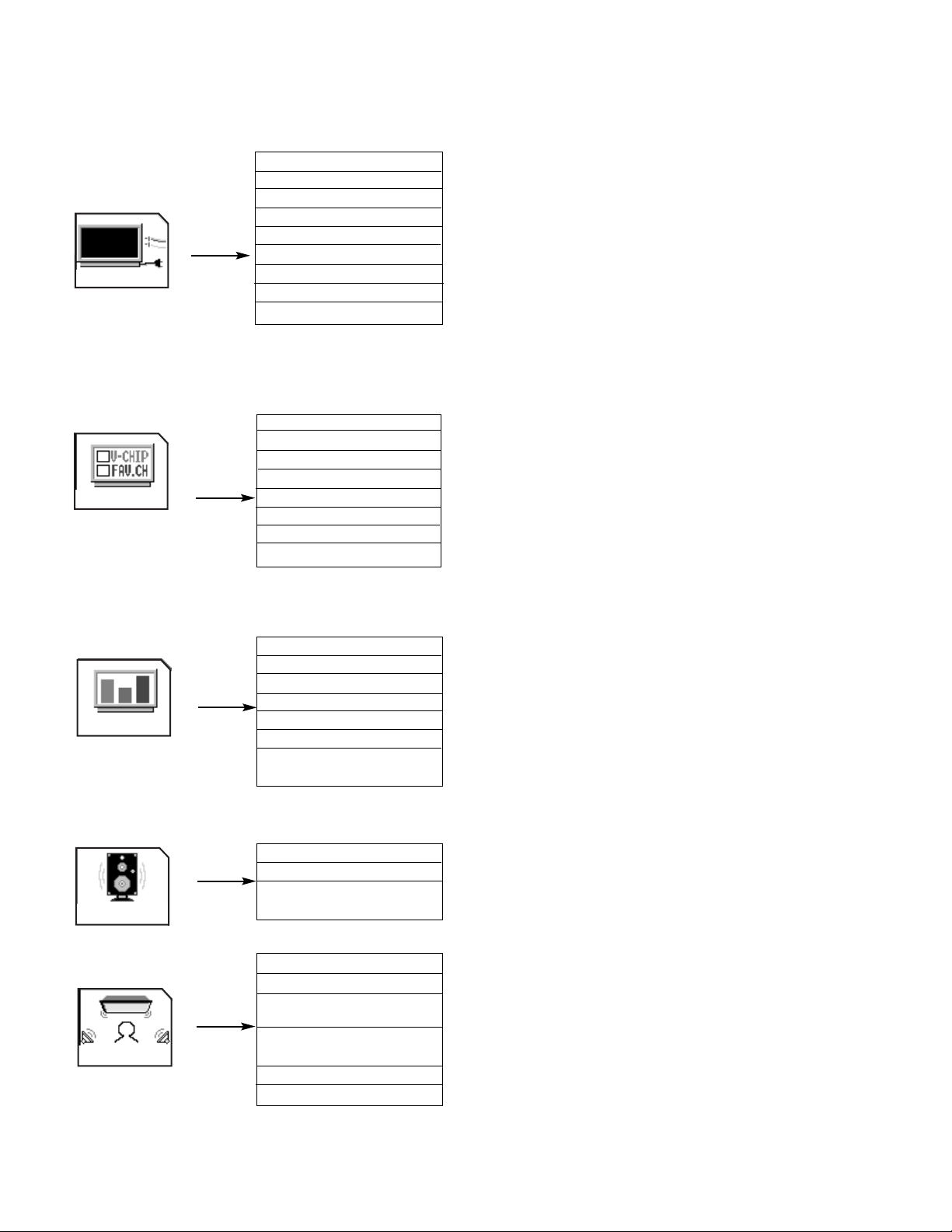
SET UP
1. MENU LANGUAGE Choose English, French, or Spanish text.
2. PLUG & PLAY Optimum hook up for your system.
3. SIGNAL SOURCE Select Antenna or Cable TV.
4. AUTO CHANNEL SET First time set up for channel buttons.
5. CHANNEL MEMORY Channel buttons, add or skip.
6. CHANNEL LIST Check channel name, scan, and child lock.
7. CLOCK SET Set before using timer features.
8. PICTURE FORMATS Select type of screen format and component input.
9. LAMP TIME Counts the hours the television has operated.
1. CHANNEL ID. Label channels PAY1, ABC, etc.
2. VIDEO ID. Label video inputs VCR1, DVD1, etc.
3. FAMILY FAVORITES Allows you to set and view favorite channels.
4. PARENTAL CONTROL Block channel picture and sound.
5. 4 EVENT PROGRAM Turn TV on and off once, daily, or weekly.
6. AUTO LINK Automatically turn TV on with any VIDEO input.
7. CLOSED CAPTION Feature to display dialogue/text.
8. MENU BACKGROUND Select from three types of backgrounds.
1. CONTRAST Adjust contrast.
2. BRIGHTNESS Adjust brightness.
3. COLOR Adjust color.
4. TINT Adjust tint.
5. SHARPNESS Adjust sharpness.
6. RESET Set VIDEO settings to factory preset.
7. ADVANCED Improve picture performance.
SETTINGS
1. EQUALIZER Precise audio control.
2. RESET Set AUDIO settings to factory preset.
3. ADVANCED Improve sound performance.
SETTINGS
1. THEATER MODES Picture and sound are automatically set.
2. SURROUND Special sound effects, including Dolby Digital.
3. INPUT SOURCE Set audio of VIDEO 1 or VIDEO 2 to analog, optical or
coaxial (digital).
4. LISTENING Set for optimum audio performance based on your
POSITION listening position.
5. LISTENING MODE Choose between Standard, Night, or Maximum.
6. SPEAKER SETUP Select specific speaker output.
CUSTOMIZE
VIDEO
AUDIO
THEATER
I. FEATURES AND FUNCTIONS
4.0 TV MODE ULTRATEC OSD FEATURES
24
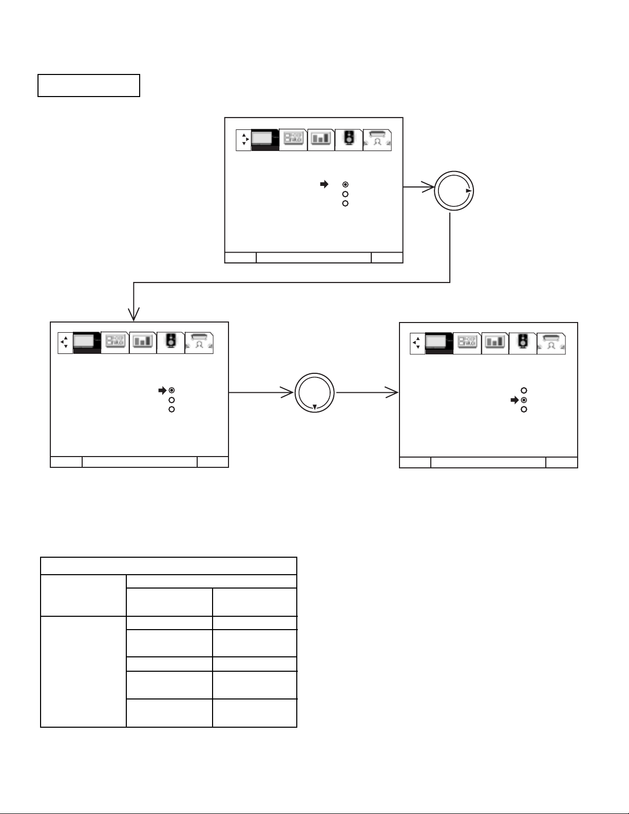
Select ANTENNA if you are using an indoor or outdoor antenna. Select CATV if you have cable TV.
Press THUMB STICK 왖 or 왔 to highlight and select the correct SIGNAL SOURCE mode.
Press EXIT to quit MENU or THUMB STICK 왗 to return to previous menu.
Reception channels for each mode are shown at the left.
Refer to your cable or TV guide for channel identification standards.
If certain CATV channels are poor or not possible in CATV1 mode,
set SIGNAL SOURCE to CATV2.
SIGNAL SOURCE
MENU TO MENU BAR TO QUIT EXIT
MENU TO MENU BAR TO QUIT EXIT
MENU TO MENU BAR TO QUIT EXIT
THUMB
STICK
THUMB
STICK
SETUP CUSTOMIZE VIDEO AUDIO THEATER
SETUP CUSTOMIZE VIDEO AUDIO THEATER
SETUP CUSTOMIZE VIDEO AUDIO THEATER
1. MENU LANGUAGE
2. PLUG & PLAY
3. SIGNAL SOURCE ANTENNA
4. AUTO CHANNEL SET CATV 1
5. CHANNEL MEMORY CATV 2
6. CHANNEL LIST
7. CLOCK SET
8. PICTURE FORMATS
9. LAMP TIME
1. MENU LANGUAGE
2. PLUG & PLAY
3. SIGNAL SOURCE ANTENNA
4. AUTO CHANNEL SET CATV 1
5. CHANNEL MEMORY CATV 2
6. CHANNEL LIST
7. CLOCK SET
8. PICTURE FORMATS
9. LAMP TIME
1. MENU LANGUAGE
2. PLUG & PLAY
3. SIGNAL SOURCE ANTENNA
4. AUTO CHANNEL SET CATV 1
5. CHANNEL MEMORY CATV 2
6. CHANNEL LIST
7. CLOCK SET
8. PICTURE FORMATS
9. LAMP TIME
RECEPTION BAND
CATV 1 OR CATV 2
AIR
VHF 2 ~ 13ch
UHF 14 ~ 69ch
CATV CHANNEL
VHF 2~13
Mid band A~1
A-5 ~ A-1
Super band J~W
Hyper band
W + 1 ~ W + 28
Ultraband
W + 29 ~ W + 84
Indicated on
the screen
2 ~ 13
14 ~ 22
95 ~ 99
23 ~ 36
37 ~ 64
65 ~ 125
I. FEATURES AND FUNCTIONS
4.1 SETUP CONT.
25
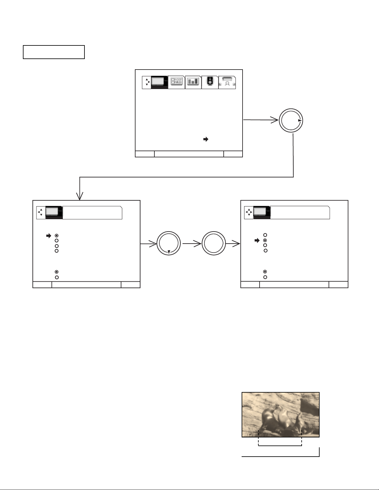
The PICTURE FORMATS function is very useful when setting up reception of High Definition, Standard
Definition and NTSC signals.
Press THUMB STICK 왖 or 왔 to highlight then press down on THUMB STICK to select Aspect Style (normal, full, fill, smooth wide)
Press EXIT to quit menu or THUMB STICK 왗 to return to previous menu.
Press THUMB STICK 왖 or 왔 to highlight V. POSITION, then THUMB STICK 왖 or 왔 to change V. POSITION.
Press THUMB STICK 왖 or 왔 to highlight V. SIZE, then THUMB STICK 왖 or 왔 to change V. SIZE.
Press THUMB STICK 왖 or 왔 to highlight then press down on THUMB STICK to select COMPONENT COLOR TYPE.
PICTURE FORMATS
PICTURE FORMATS ANT A 3
ASPECT STYLE
NORMAL
FULL
FILL
SMOOTH WIDE
V. POSITION 0
V. SIZE +15
COMPONENT COLOR TYPE
HDTV
SDTV/DVD
MENU TO MENU BAR TO QUIT EXIT
THUMB
STICK
THUMB
STICK
MENU TO MENU BAR TO QUIT EXIT
SETUP CUSTOMIZE VIDEO AUDIO THEATER
MENU TO MENU BAR TO QUIT EXIT
THUMB
STICK
PRESS SELECT TO
ACTIVATE/DEACTIVATE
PRESS SELECT TO
ACTIVATE/DEACTIVATE
PICTURE FORMATS ANT A 3
ASPECT STYLE
NORMAL
FULL
FILL
SMOOTH WIDE
V. POSITION 0
V. SIZE +15
COMPONENT COLOR TYPE
HDTV
SDTV/DVD
1. MENU LANGUAGE
2. PLUG & PLAY
3. SIGNAL SOURCE
4. AUTO CHANNEL SET
5. CHANNEL MEMORY
6. CHANNEL LIST
7. CLOCK SET
8. PICTURE FORMATS
9. LAMP TIME
SETUP
SETUP
SELECT
Normal Choose this when receiving a 4:3 image and you want the on-screen
appearance of the video to be a centered picture with side panels
(blank areas) on the right and left sides.
Full Choose this when you want the television to adjust the 4:3 image hor-
izontally so it fills your 16:9 screen. No side panels will be added, and
the image is vertically unaltered. This setting is especially useful for
viewing 16:9 formatted DVDs.
ASPECT STYLE
If you receive an image with a 4:3 aspect ratio, the image will be displayed at that ratio on your TV unless you specify otherwise. The
Picture Format menu allows you to adjust the image through the following options:
4:3 ratio
16:9 ratio
I. FEATURES AND FUNCTIONS
4.1 SETUP CONT.

26
V. POSITION
This function allows you to select when aspect style is either Full or Fill or Smooth Wide. Vertical position can be changed with this
mode. For example, it will be useful for centering the picture when there is gray area at both top and bottom of the picture with HDTV
signal. Adjustable range is -10 (video center is toward bottom of screen) to +10 (video center is toward top of screen).
Fill This function allows you to select when receiving either NTSC or
SDTV. Full screen picture is available in this mode when receiving letterbox signal. Both vertical edges will be hidden if you
select Fill for ordinary 4:3 picture.
Smooth Wide This function allows you to select when receiving either NTSC or
SDTV signal. 4:3 picture is expanded horizontally as being close
to both left and right sides. It keeps 4:3 ratio in the center of the
picture, then expands as it is close to both left and right edge of
the picture to show picture distortion minimized. This function
allows you to watch picture without side panel for 4:3.
ASPECT STYLE
Some digital (ATSC format)
stations may transmit 4:3
images in a way that will
not allow expansion. You
will be unable to adjust the
picture format.
NOTES: 1. The aspect Style setting you select for an ANT input will automatically be set for the other ANT input. However, all three
video inputs have independent Aspect Style settings.
2. You will not be able to access the V. Position menu if Aspect Style-Normal is set.
3. You will not be able to access the V. SIZE menu if Aspect Style - Normal or Full is set.
4. You will only be able to access the Aspect Style menu when viewing a 4:3-480i or 480P. When viewing a 16:9-1080i
or 720P input you will not be able to access this menu.
5. If COMPONENT COLOR TYPE is set improperly (does not match actual input signal), the color and tint of the main
picture will be abnormal.
6. You must be tuned to VIDEO: 1 or 2 input and have a component hooked up to the Y-PBPRinput jacks to
access this component color type.
7. All component color type settings will affect only color component input you are currently viewing. If you are using
both sets of component input jacks, be sure to set the component color type feature for both inputs.
8. Adjustable range of V. Position is -20 to +20 when receiving 480P picture.
COMPONENT COLOR TYPE
This function allows you to automatically change tint and color coordinates for DTV programs.
HDTV - High Definition Television - Use for High Vision Signal Y-PBPRfrom HDTV Set-Top Box.
SDTV /DVD - Standard Definition Television or DVD (Digital Versatile Disc Player) Y-CBCR.
V. SIZE
This function allows you to select when aspect style is Fill. It will not be available when selecting other aspect style. It is useful when
you wish to change vertical size of the picture. Adjustable ranges is -15 (video size is narrowed) to +15 (video size is broadened).
I. FEATURES AND FUNCTIONS
4.1 SETUP CONT.
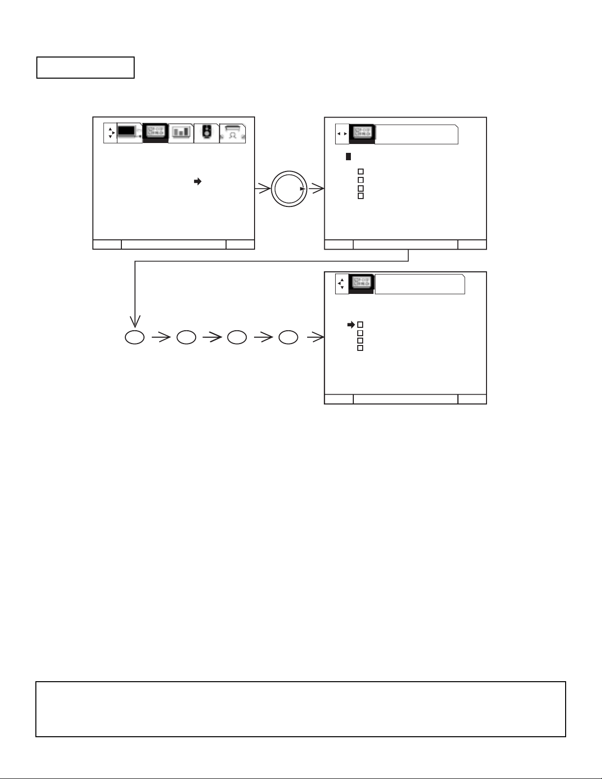
27
This function will block out the picture and sound of the selected channel or video input.
It can also be used to keep the TV from being viewed for a scheduled amount of time that you set.
The code to enter PARENTAL CONTROL is a four digit secret code number. The factory preset code is 0000.
Use the number buttons to select secret code.
Use THUMB STICK 왖 or 왔 to highlight function and press down on the THUMB STICK to set ON or OFF.
When CHANNEL is turned on, the picture and sound for the chosen channel will be blocked out.
When VIDEO LOCK is turned on, the picture and sound for all video inputs will be blocked out. To lock the video inputs, you must
be tuned to one of the video inputs.
When QUICK LOCK is turned on, the picture and sound for channels 3, 4 on both ANT A/B and all video inputs will be blocked out.
When FRONT PANEL LOCK is turned on, all buttons on the Front Panel will be deactivated, except the POWER button.
When TV TIME OUT is turned on, you can set the BEGIN and END times and the TV cannot be viewed during that time period.
(Set clock first.) Use THUMB STICK 왖 or 왔 to highlight ONCE (TV will time out one time only), DAILY (TV will time out every
day), WEEKLY (TV will time out one time a week) or OFF (to disable this function) and then press down on THUMB STICK to
SELECT your choice.
MOVIE RATINGS, TV RATINGS, and CANADIAN RATINGS are explained in detail in the Parental Control Movie/TV Ratings Reference
Guide.
To change the secret code number, select CHANGE SECRET CODE. Enter a new four digit key number you prefer.
If you forget your secret code, use the factory code 7777 to erase your key number. This will reset the secret code number back to the
factory preset 0000.
Press EXIT to quit menu or THUMB STICK 왗 to return to previous menu.
PARENTAL CONTROL
MENU TO MENU BAR TO QUIT EXIT
MENU TO MENU BAR TO QUIT EXITMENU TO MENU BAR TO QUIT EXITMENU TO MENU BAR TO QUIT EXIT
USE NUMBER BUTTONS TO
ENTER THE SECRET CODE
MENU TO MENU BAR TO QUIT EXITMENU TO MENU BAR TO QUIT EXITMENU TO MENU BAR TO QUIT EXIT
THUMB
STICK
PRESS SELECT TO
ACTIVATE/DEACTIVATE
1. CHANNEL ID.
2. VIDEO ID.
3. FAMILY FAVORITES
4. PARENTAL CONTROL
5. 4 EVENT PROGRAM
6. AUTO LINK
7. CLOSED CAPTION
8. MENU BACKGROUND
PARENTAL CONTROL
**** ENTER SECRET CODE
CHANNEL 3
VIDEO LOCK
QUICK LOCK
FRONT PANEL LOCK
TV TIME OUT
MOVIE RATINGS
TV RATINGS
CANADIAN RATINGS (ENG)
CANADIAN RATINGS (FRN)
PARENTAL CONTROL
**** CHANGE SECRET CODE?
CHANNEL 3
VIDEO LOCK
QUICK LOCK
FRONT PANEL LOCK
TV TIME OUT
MOVIE RATINGS
TV RATINGS
CANADIAN RATINGS (ENG)
CANADIAN RATINGS (FRN)
0 0 0 0
SETUP CUSTOMIZE VIDEO AUDIO THEATER
CUSTOMIZE
CUSTOMIZE
NOTE: 1. If ANT A and ANT B are in the same SIGNAL SOURCE mode, when a channel is locked, it is locked
on both antenna inputs.
2. When using TV TIME OUT make sure the clock is set.
3. When the RECALL button is pressed, text appears on the screen to indicate that CHILD LOCK is activated.
I. FEATURES AND FUNCTIONS
4.2 CUSTOMIZE
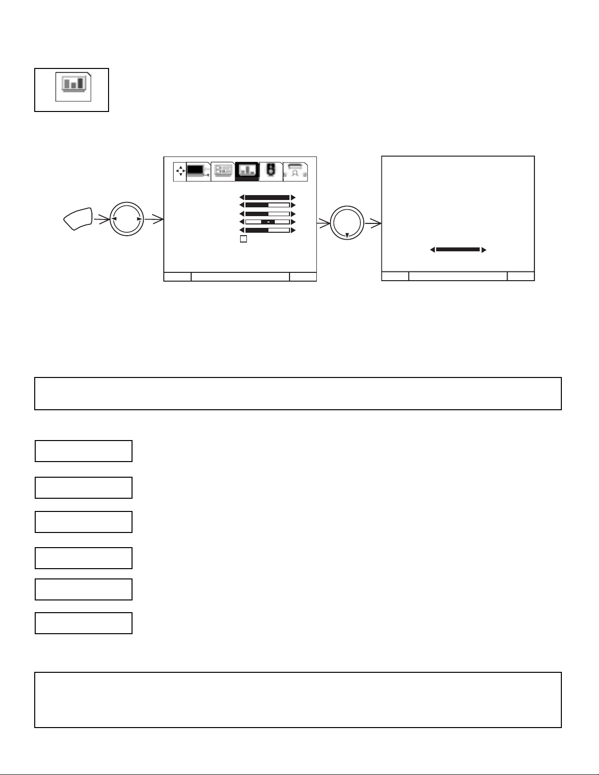
28
VIDEO
Select VIDEO to adjust picture settings and improve picture quality.
Use this function to change the contrast between black and white levels in the picture. This adjustment will
only affect the picture when ADVANCED SETTINGS PERFECT PICTURE is OFF.
Use the THUMB STICK 왖 or 왔 to highlight the function to be adjusted.
Press the THUMB STICK 왗 or 왘 to adjust the function.
Press EXIT to quit menu.
NOTE: If CONTRAST is selected, you are adjusting CONTRAST. The additional menu items BRIGHTNESS, COLOR, TINT,
and SHARPNESS can be selected and adjusted in the same manner.
Use this function to adjust the level of color in the picture.
Use this function to adjust flesh tones so they appear natural.
Use this function to adjust overall picture brightness.
Use this function to adjust the amount of fine detail in the picture.
When RESET is selected, press down (SELECT) on THUMB STICK to return video adjustments to factory
preset conditions.
CONTRAST
COLOR
TINT
BRIGHTNESS
SHARPNESS
RESET
NOTES: 1. It may be necessary to adjust TINT to obtain optimum picture quality when using the COMPONENT VIDEO Y-PBP
R
input jacks.
2. If you are using the COMPONENT VIDEO input jacks (Y-PBPR) and notice that the TINT and COLOR are abnormal,
check to make sure that PICTURE FORMATS - COMPONENT COLOR TYPE is set properly.
I. FEATURES AND FUNCTIONS
4.3 VIDEO
SETUP CUSTOMIZE VIDEO AUDIO THEATER
THUMB
STICK
MENU
1. CONTRAST
2. BRIGHTNESS
3. COLOR
4. TINT
5. SHARPNESS
6. RESET
7. ADVANCED
SETTINGS
100%
50%
50%
50%
THUMB
STICK
CONTRAST
100%
MENU TO MENU BAR TO QUIT EXIT
MENU TO MENU BAR TO QUIT EXIT
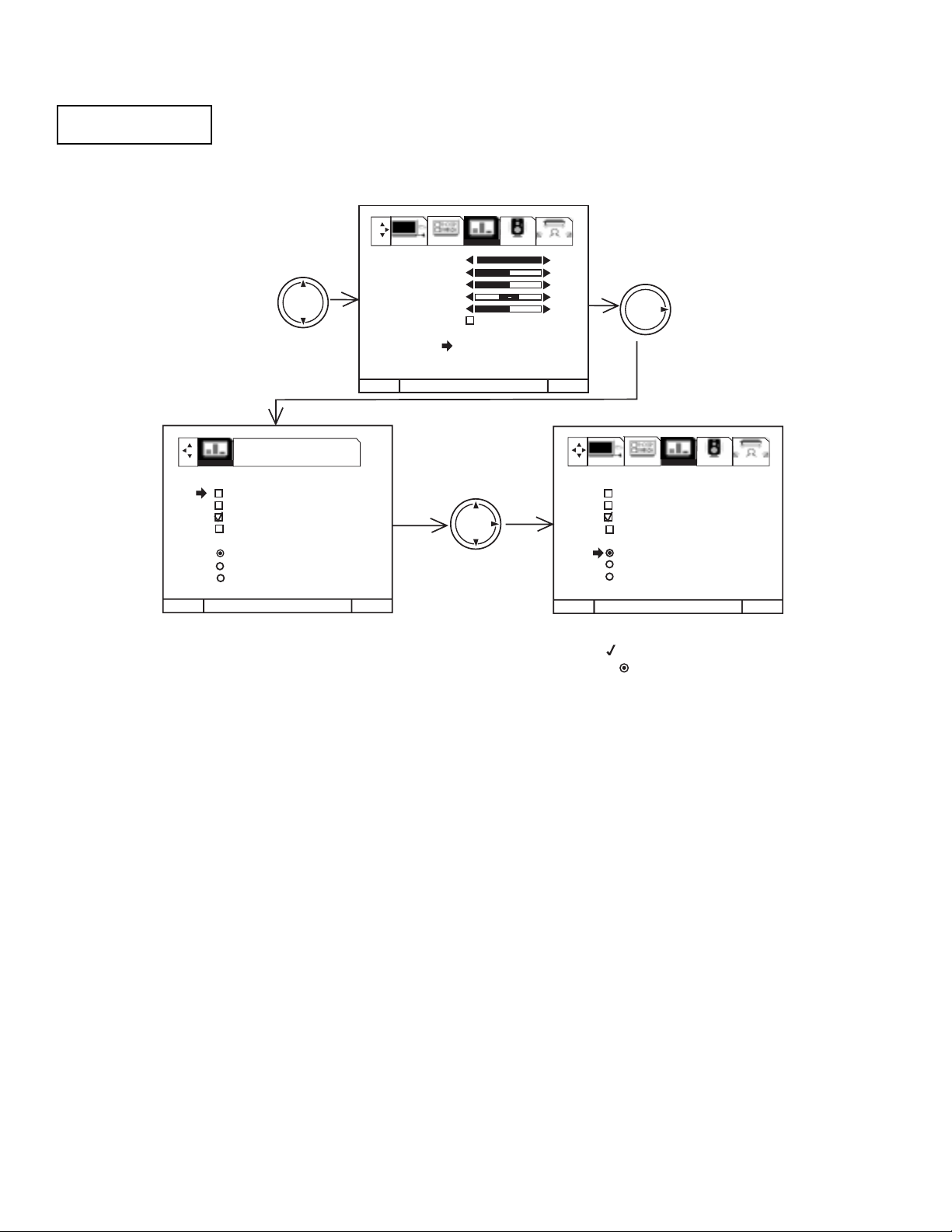
29
Your HITACHI Projection TV has a PERFECT PICTURE function which will automatically adjust picture
settings to produce the highest quality picture possible.
When PERFECT PICTURE is highlighted, press down on THUMB STICK to turn the PERFECT PICTURE on
or off.
Use THUMB STICK 왖 or 왔 to select function.
Press down on THUMB STICK to select the function setting. When the function has an Ò Ó in the box, it is ON.
Use THUMB STICK 왘 to change COLOR TEMPERATURE. When the function shows a Ò Ò, it is selected.
Press EXIT to quit menu or THUMB STICK 왗 to return to previous menu.
PERFECT PICTURE
When the PERFECT PICTURE function is on, the TVsÕ internal computer will perform the following:
1. Automatically monitor and adjust contrast depending on room lighting (sensor is located in the front panel) to produce a more
natural picture.
2. Automatically monitor and adjust color levels and maintain natural flesh tones.
3. Automatically compensate for weak or strong TV signals to produce a clear picture.
Turn the PERFECT PICTURE function off to control other PREFERENCE SETTINGS.
AUTO COLOR
The AUTO COLOR function automatically monitors and adjusts the color to maintain constant color levels even after a program or
channel changes. It also maintains natural flesh tones while preserving fidelity of background colors. (This function will automatically
set to on and cannot be turned off when the PERFECT PICTURE function is ON.) This function does not operate with a COMPONENT:
Y-PBPRinput signal.
NOISE REDUCTION
The NOISE REDUCTION function automatically reduces conspicuous noise in the picture without degrading picture quality.
(This function will automatically be set to on and cannot be turned off when the PERFECT PICTURE function is ON.)
AUTO DYNAMIC CONTRAST
The AUTO DYNAMIC CONTRAST function automatically monitors and adjusts the color to maintain constant contrast levels even after
a program or channel changes. It also maintains natural flesh tones while preserving fidelity of background colors. (This function will
automatically set to on and cannot be turned off when the AUTO DYNAMIC CONTRAST function is ON.) This function does not operate
with a COMPONENT: Y-PBPRinput signal.
COLOR TEMPERATURE
Set this to WARM for hotter colors with more red, or set to COOL for less intense colors with more blue or STANDARD for standard
color.
ADVANCED
SETTINGS
MENU TO MENU BAR TO QUIT EXIT
MENU TO MENU BAR TO QUIT EXIT
MENU TO MENU BAR TO QUIT EXIT
THUMB
STICK
THUMB
STICK
THUMB
STICK
100%
50%
50%
50%
PRESS SELECT TO
ACTIVATE/DEACTIVATE
1. CONTRAST
2. BRIGHTNESS
3. COLOR
4. TINT
5. SHARPNESS
6. RESET
7. ADVANCED
SETTINGS
VIDEO
SETUP CUSTOMIZE VIDEO AUDIO THEATER
SETUP CUSTOMIZE VIDEO AUDIO THEATER
ADVANCED SETTINGS
PERFECT PICTURE
AUTO COLOR
NOISE REDUCTION
AUTO DYNAMIC CONTRAST
COLOR TEMPERATURE
COOL
WARM
STANDARD
ADVANCED SETTINGS
PERFECT PICTURE
AUTO COLOR
NOISE REDUCTION
AUTO DYNAMIC CONTRAST
COLOR TEMPERATURE
COOL
WARM
STANDARD
I. FEATURES AND FUNCTIONS
4.3 VIDEO (CONT.)
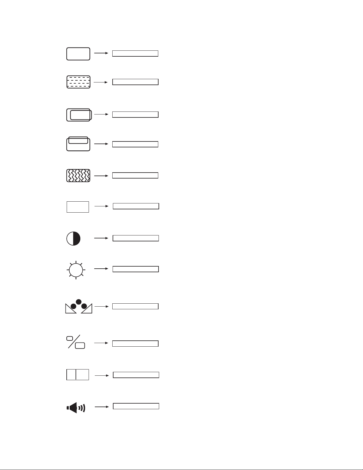
30
ENHANCE
Enhance picture details.
EXPANSION
Increase the horizontal size and vertical
size.
Adjusts the phase to correct blurred or
unstable images.
PHASE
Adjusts the dot clock frequency to reduce
the vertical stripe.
CLOCK
Adjust overall picture brightness.
BRIGHTNESS
Change the contrast between black and white levels in the picture.
CONTRAST
Adjust vertical position.
V POSITION
Adjust horizontal position.
H POSITION
DATA RECALL
Recall the factory preset data of PC settings.
AUTO ADJUST
Automatically adjust the geometry to fit the screen.
COLOR BALANCE
Balance between Red and Blue color.
AUDIO EQUALIZER
Enhance audio quality.
AUTO
R
E
ON
OFF
I. FEATURES AND FUNCTIONS
5.0 PC MODE ULTRATEC OSD FEATURES
 Loading...