

Hitachi 55DMX01W Owner’s Manual
DLPTMTECHNOLOGY REAR PROJECTION TELEVISION
OPERATING GUIDE
IMPORTANT SAFEGUARDS
FIRST TIME USE 5-24
THE REMOTE CONTROL 25-37
ULTRATEC BIT MAP
ON SCREEN DISPLAY
USING THE DLP TMTECHNOLOGY
REAR PROJECTION TV AS A PC
MONITOR
2-4
38-68
69-79
LAMP REPLACEMENT
PLUG AND PLAY
TRADEMARK ACKNOWLEDGMENT
AGENCY REGULATORY INFORMATION
USEFUL INFORMATION
SPECIFICATIONS
SERVICE HOTLINE
FEATURE INFORMATION
C Lp. Digital Light Processing, DLP, Digital Micromirror Device and DMD are trademarks of Texas Instruments.
A]BU6IIISflIIIIB_E0{X0L06f
The DLP logo is a trademanrk of Texas Instruments.
80-91

Follow all warnings and instructions marked on this Rear Projection Television.
IMPORTANT
,_,_, WARNING
CAUTION: TO REDUCE THE RISK OF ELECTRIC SHOCK,
REFER SERVICING TO QUALIFIED SERVICE PERSONNEL.
RISK OF ELECTRIC SHOCK
DO NOT OPEN
DO NOT REMOVE COVER (OR BACK).
NO USER SERVICEABLE PARTS INSIDE.
_ I _, _ _ :!aa_nnc_e:_ti!1sia;fv!_ittdad_!_`_ic!:snrttti:h:_eee_ursa_r!!_ct_he_ne!:r_eis_tehtehc`!ftuiy_!s!:t!da
The lightning flash with arrowhead symbol, within an equilateral
The exclamation point within an equilateral triangle, is intended to
alert the user to the _ of important operating and
maintenance (servicing) instructions in the literature accompanying
the appliance.
WARNING:
TO PREVENT FIRE OR SHOCK HAZARD, DO NOT EXPOSE
THIS REAR PROJECTION TELEVISION TO RAIN OR MOISTURE.
NOTE: ¥There are no user serviceable parts inside the Rear Projection Television.
¥Model and serial numbers are indicated on back side of the Rear Projection
Television.
I CAUTION: TO PREVENT ELECTRIC SHOCK, MATCH WIDE BLADE OF PLUG TO WIDE SLOT, FULLY INSERT I
CAUTION: Adjust only those controls that are covered in the instructions, as improper changes or modifications
not expressly approved by HITACHI could void the user s warranty.
MODIFICATIONS: The FCC requires the user to be notified that any changes or modifications made to this device that
are net expressly approved by Hitachi America, Ltd. Home Electronics Division may void the user s
warranty,
POWER SOURCE
This Rear Projection Television is designed to operate on 120 Volts 60Hz, AC
current. Insert power cord into a 120 Volt 60Hz outlet.
TO PREVENT ELECTRIC SHOCK, DO NOT USE THE REAR PROJECTION
TELEVISION S PLUG WITH AN EXTENSION CORD, RECEPTACLE, OR OTHER OUTLET
UNLESS THE BLADES AND GROUND TERMINAL CAN BE FULLY INSERTED TO
PREVENT BLADE EXPOSURE.
NEVER CONNECT THE DLP TM REAR PROJECTION TELEVISION TO 50HZ, DIRECT
CURRENT, OR ANYTHING OTHER THAN THE SPECIFIED VOLTAGE.
This Rear Projection Television receiver will display closed captioning, (_c"_ or [_ ), in accordance
I NOTE:
with paragraph 15.119 of the FCC rules.
_. CAUTION: Never remove the back cover of the Rear Projection Television as this can expose you to very high voltages
and other hazards. If the Rear Projection Television does net operate properly, unplug the Rear Projection
Television and call your authorized dealer or service shop.
2

IMPORTANT
IMPORTANT SAFEGUARDS
CAUTION:
¥ Read all of these instructions.
¥ Save these instructions for later use.
SAFETY POINTS YOU SHOULD KNOW ABOUT YOUR
HITACHI REAR PROJECTION TELEVISION
RECEIVER
¥ Follow all warnings and instructions marked
on the Rear Projection Television receiver.
Our reputation has been built on the qua@y, performance, and ease of service of HITACHI Rear Projection Television receivers
Safety is also foremost in our minds Jn the design of these units TO help you operate these products properly, this section illustrates safety tips which will be of benefit to you
Please read Jt carefuJJy and apply the knowledge you obtain from Jt to the proper operation of your HITACHI Rear Projection Television receiver
Please fiJJ out your watYanty card and mail it to HITACH This will enable HTACH to notify you promptly in the improbable event that a safety problem should be discovered in
your product model
FORYOURPERSONALSAFETY
1 This Rear Projection Television set is equipped with
a polarized alternating-current line plug (a plug
having one blade wider than the Other i This plug
will tit into the power outlet only one way This is a
safety feature¸ if you are unable to insert the plug
fully into the power outlet, try reversing the plug if
the p_ug should still fail to fit, contact your electrlcJan
to replace your obsolete outlet Do not defeat the
safety purpose of the polarized plug
2 When the power col_l or plug is damaged or frayed,
unplug the Rear Projection Television set from the
wall outJet and refer sen4cing to qualified service
personnel
3 Do not overload wall outJets and extension cords as
this can result Jnfire or electric shock¸
7 If the Rear Projection Television set has been
dropped or the cabinet has been damaged, unplug
the Rear Projection Television set from the wall
outlet and refer servicing to qualified service
personnel
8 if liquid has been spilled into the Rear Projection
Television set, unplug it from the wall outlet and
refer service to qualified service personnel
9 Do not subject your Rear Projection Television set
to impact of any kind Be careful not to damage the
screen surface
10 Unplug the Rear Projection Television set from the
wall outlet before c_eaning Use a damp cloth for
cleaning Do not use liquid or aerosol cleaners
4 Do not allow anything to rest on or rell over the
power cord, and do not place the Rear Projection
Television where the power cord is subject to traffic
or abuse¸ This may result in a shock or fire hazard¸
5 Do not attempt to service the Rear Projection
Television set yourseJf as opening or removing
covers may expose you to dangerous voltage or
other hazards¸ Refer all servicing to qualified
service personnel¸
6 Never push objects of any kind into the Rear
Projection Television sets cabinet slots as they may
touch dangerous voltage points or short out pads
that could result in a fire or electric shock¸ Never
spill liquid of any kind on the Rear Projection
Television set.
PROTECTION AND LOCATION OF YOUR SET
12 Do not use the Rear Projection Television set near
water, for example, near a bathtub, washbowl,
kitchen sink, or laundry tub, in a wet basement, or
near a swimming pool, etc
¥ Never expose the set to rain or water If the set has
been exposed to rain or water, unplug set from walJ
outlet and refer to qualified sen/ice personnel
13 Choose a place where light (artificial or sunlight)
does not shine directly on the screen
14 Avoid dusty places, since accumulated dust inside
the chassis may cause failure of the set when high
humidity persists
11-1 Do not place the Rear Projection Television set
on an unstable cart, stand, or table The Rear
Projection Television set may fall, causing
serious injury to a child or an adult, and serious
damage to the appliance Use only with a cart or
stand recommended by the manufacturer, or
sold with the Rear PrejectJon Television set Wall
or shelf mounting should follow the
manufacturers instructions, and should use a
mounting kit approved by the manufactuler
11-2
An appliance and cart combination should be
moved with care Quick stops, excessive force,
and uneven surfaces may cause the appliance
and cart combination to overturn¸
15 The set has s_ots or openings in the cabinet for
ventNation purposes which provide reliable
operation of the receiver and protect the Rear
Projection Television from overheating These
openings must not be blocked or covered
¥ Never cover the slots or openings with cloth or
other material
¥ Never block the bottom ventilation slots of the set
by placing it on a bed, sofa, rug, etc
¥ Never place the set near or over a radiator or heat
generator¸
¥ Never place the set in a built-in enclosure, unless
proper ventilation is provided
3
/k
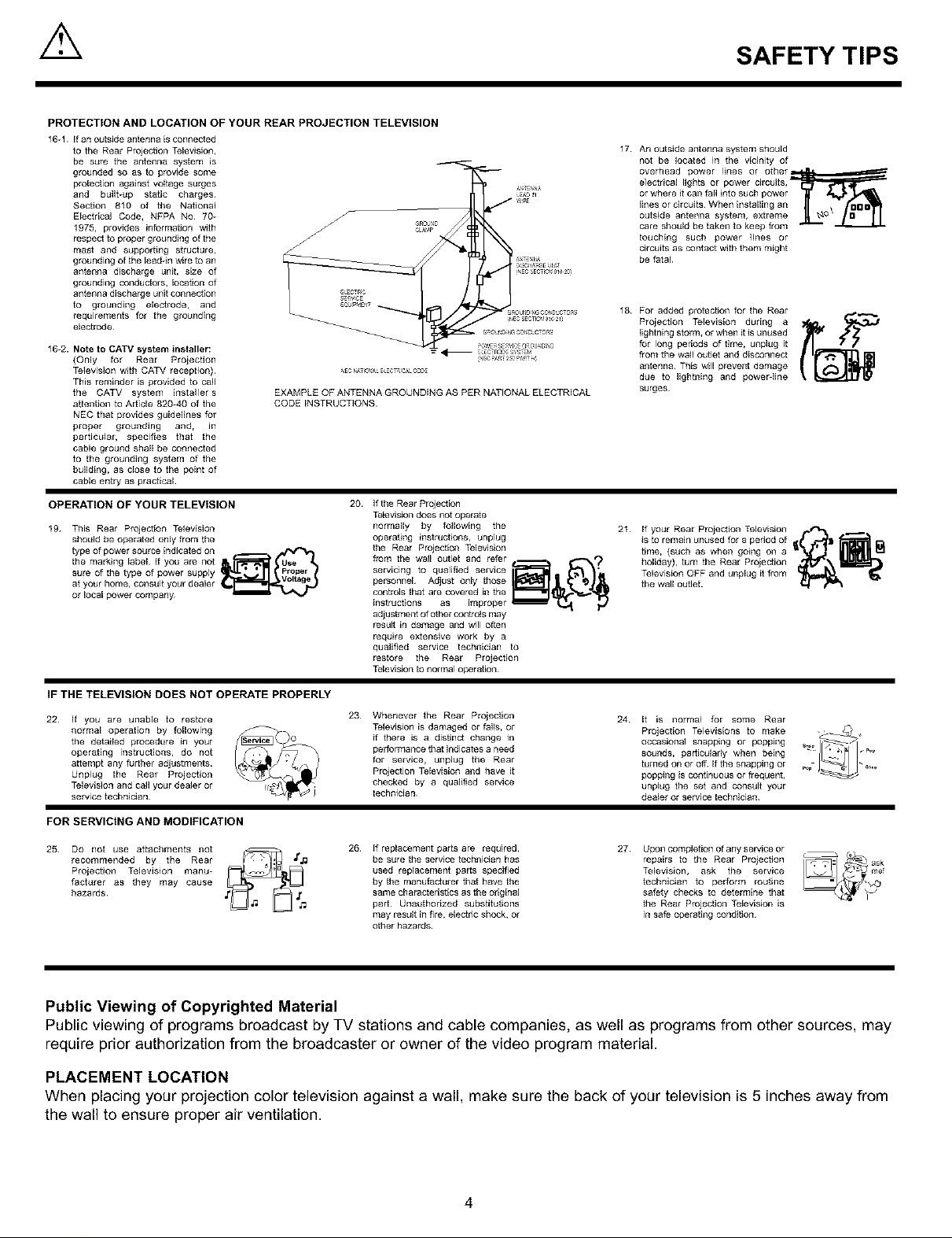
PROTECTION AND LOCATION OF YOUR REAR PROJECTION TELEVISION
16-1 if an outside antenna isconnected
to the Rear Projection Television,
be sure the antenna system is
grounded so as to provide some
protection against voltage surges
and built-up static charges¸
Section 810 of the National
Electrical Code, NFPA No 70_
1975, provides information with
respect to proper grounding of the
mast and supporting structure,
grounding of the lead4n wire to an
antenna discharge unit, size of
grounding conductors, location of
antenna discharge unit connection
to grounding electrode, and
requirements for the grounding
electrode¸
16-2. Note to CATV system installer:
{Only for Rear Projection
Television with CATV reception)
This reminder is provided to call
the CATV system installer s
attention to Article 820_40 of the
NEe that provides guidelines for
proper grounding and, in
particular, specifies that the
cable ground shall be connected
to the grounding system of the
building, as close to the point of
cable entry as practical
OPERATION OF YOUR TELEVISION
19 This Rear Projection Television
should be operated only from the
type of power source indicated on . ._
the marking label If you are not
sure of the type of power supply
at your home, consult your dealer
or local power company
IF THE TELEVISION DOES NOT OPERATE PROPERLY
22 If you are unable to restore
normal operation by following
the detailed procedure in your
operating instructions, do not
attempt any further adjustments
Unplug the Rear Projection
Television and carl your dealer or
service technician
FOR SERVICING AND MODIFICATION
25 Do not use attachments not
recommended by the Rear
Projection Television manu-
facturer as they may cause
hazards
EXAMPLE OFANTENNA GROUNDING AS PER NATIONALELECTRICAL
CODEiNSTRUCTIONS
20
If the Rear Projection
Television does not operate
normally by following the
operating instructions, unplug
the Rear Projection Television
fzom the wall outlet and refer _ _,,,_?
personnel Adjust only thOSe
controls that are covered in the
instructions as improper _
adjustment of other cont_ls may
result in damage and will often
require extensive work by a
qualified service technician to
restore the Rear Projection
Television to normal operation¸
23 Whenever the Rear Proiection
Television is damaged or falls, or
if there is a distinct change in
performance that indicates a need
for service, unplug the Rear
Projection Television and have it
checked by a qualified service
technician
26 If replacement parts are required,
be sure the service technician has
used replacement parts specified
by the manufacturer that have the
same characteristics as the original
part¸ Unauthorized substitutions
may result in fire, electric shock, or
other hazards¸
SAFETY TIPS
17
An outside antenna system should
not be located in the vicinity of
overhead power lines or other_
e]ectrica[ lights or power circuits,
or where it call fall into such power
lines or circuits When installing an
outside antenna system, extreme
care should be taken to keep from
touching such power lines or
circuits as contact with them might
be fatal
18
For added protection for the Rear
Projection Television during a
lightning storm, or when it is unused
for long periods of time, unplug it
flora the wall outlet and disconnect
antenna This will prevent damage
due to lightning and powerdine
surges
21 If your Rear Projection Television r._*-_ ._.
is to remain unused for a period of
time, (such as when going on a
holiday), turn the Rear Projection
Television OFF and unplug it flora
the wall outJet.
24 It is normal for some Rear
occasional snapping or popping _
sounds, particularly when being
turned on ot off If the snapping or _,._
popping is continuous ot frequent,
unplug the set and consult your
dealer or service technician
27
Upon completion of any service or
repairs to the Rear Projection
Television, ask the service
technician to perform routine
safety checks to determine that
the Rear Projection Television is
in safe operating condition
Televisions to make _'_ ,,Projection
Public Viewing of Copyrighted Material
Public viewing of programs broadcast by TV stations and cable companies, as well as programs from other sources, may
require prior authorization from the broadcaster or owner of the video program material.
PLACEMENT LOCATION
When placing your projection color television against a wall, make sure the back of your television is 5 inches away from
the wall to ensure proper air ventilation.
4
ACCESSORIES
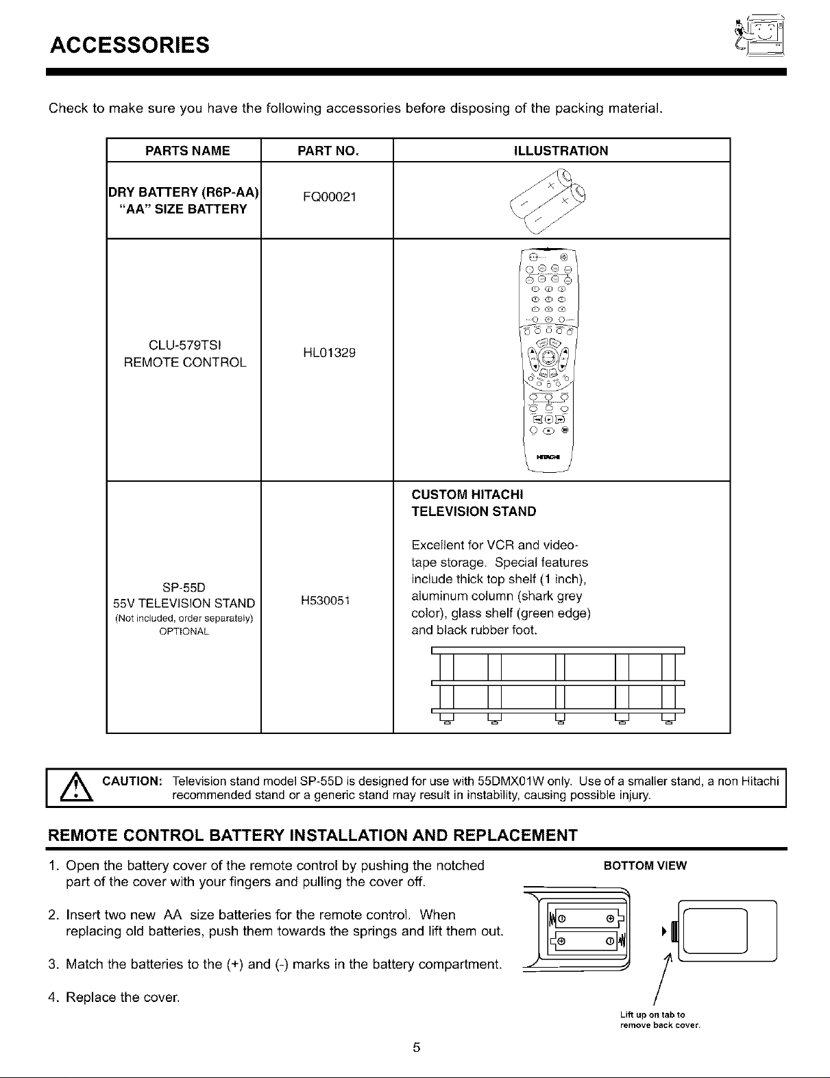
Check to make sure you have the following accessories before disposing of the packing material.
PARTS NAME PART NO. ILLUSTRATION
)RY BATTERY (R6P-AA) FQ00021
"AA" SIZE BATTERY
®®®@
@@@
@@@
@%@@
....0 @ 0 ......
CLU-579TSI
REMOTE CONTROL
SP-55D
55V TELEVISION STAND
(Not included,order separately)
OPTIONAL
HL01329
H530051
©@ee
CUSTOM HITACHI
TELEVISION STAND
Excellent for VCR and video-
tape storage. Special features
include thick top shelf (1 inch),
aluminum column (shark grey
color), glass shelf (green edge)
and black rubber foot.
r i
II II II II II
II II II II II
L_J L_J L_ L_ L_
Z_k CAUTION: Television stand model SP-55D is designed for use with 55DMX01W only. Use of a smaller stand, a non Hitachi
REMOTE CONTROL BATTERY INSTALLATION AND REPLACEMENT
1. Open the battery cover of the remote control by pushing the notched BOTTOMVIEW
part of the cover with your fingers and pulling the cover off.
replacing old batteries, push them towards the springs and lift them out.
3. Match the batteries to the (+) and (-) marks in the battery compartment.
2. Insert two new AA size batteries for the remote control. When l__eo _] i_I
4. Replace the cover.
recommended stand or a generic stand may result in instability, causing possible injury.
Lift up on tab to
remove back cover.
5
]
]
HOW TO SET UP YOUR NEW
HITACHI DLPTMREAR PROJECTION TV
ANTENNA
Unless your Rear Projection TV is connected to a cable TV system or to a centralized antenna system, a good outdoor color TV
antenna is recommended for best performance, However, if you are located in an exceptionally good signal area that is free from
interference and multiple image ghosts, an indoor antenna may be sufficient.
LOCATION
Select an area where sunlight or bright indoor illumination will not fall directly on the picture screen. Also, be sure that the location
selected allows a free flow of air to and from the perforated back cover of the set.
To avoid cabinet warping, cabinet color changes, and increased chance of set failure, do not place the Rear Projection TV where
temperatures can become excessively hot, for example, in direct sunlight or near a heating appliance, etc.
VIEWING
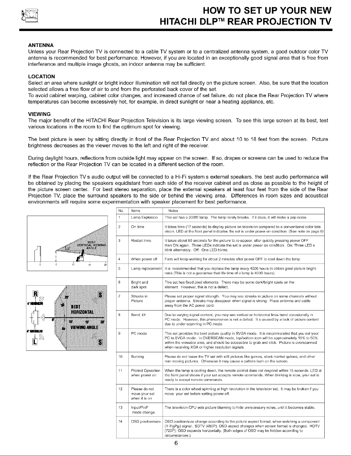
The major benefit of the HITACHI Rear Projection Television is its large viewing screen. To see this large screen at its best, test
various locations in the room to find the optimum spot for viewing.
The best picture is seen by sitting directly in front of the Rear Projection TV and about 10 to 18 feet from the screen. Picture
brightness decreases as the viewer moves to the left and right of the receiver.
During daylight hours, reflections from outside light may appear on the screen, If so, drapes or screens can be used to reduce the
reflection or the Rear Projection TV can be located in a different section of the room.
If the Rear Projection TV s audio output will be connected to a Hi-Fi system s external speakers, the best audio performance will
be obtained by placing the speakers equidistant from each side of the receiver cabinet and as close as possible to the height of
the picture screen center, For best stereo separation, place the external speakers at least four feet from the side of the Rear
Projection TV, place the surround speakers to the side or behind the viewing area. Differences in room sizes and acoustical
environments will require some experimentation with speaker placement for best performance.
No Items
1 Lamp Explosion
2 On time It takes time (17 seconds) to display picture on television compared to a conventional color tele
3 Restart time It takes about 60 seconds for the picture to re-appear, after quickly pressing power OFF
4 When power off Fans will keep working for abe/it 2 minutes after power OFF to cool down the lamp
5 Lamp replacement It is recommended that you replace the lamp every 4000 he/its to obtain good picture bright-
6 Bright and This set has fixed pixel elements There may be some dark/bdght spots on the
dark spot element However, this is not a defect
7 Sbeaks in Please set proper signal strength You may see streaks in picture on some channels without
Picture proper antenna Streaks may disappear when signal is strong Place antenna and cable
8 Bend, tilt Due to varying signal content, you may see ver[ical or honzontal lines bend occasionally En
9 PC mode This set provides the best picture quality in SVGA mode It is recommended that you set yo/ir
10 Burning Please do not leave the TV set with still pictures like games, stock market qutoes, and other
11 Protect Operation When the lamp is cooling down, the remote control does not respond within 15 seconds LED at
when power on the front panel shows if your set accepts remote commands When blinking is slow, your set is
12 Please do not There is a color wheel spinning at high revolution in the television set g may be broken g yo/i
move your set move yo/ir set before setting power off
when it is on
13 Input/PinP The television CPU sets picture blanking to hide unnecessary noise, until it becomes stable
mode change
14 OSD position/size OSD position/size change according to the picture aspect format, when watching a component
Notes
This set has a 200W lamp The lamp rarely breaks If it does, it will make a pop noise
vision LED at the front panel indicates the set is under power on condition (See note on page 9)
then ON again Three LEDs indicate the set is under power on condition On: Three LED s
blink alternately Off: One LED blinks
ness (This is not a g/larantee that life time of a lamp is 4000 hours)
away from the AC power cord
PC mode However, this phenomenon is not a defect It s ca/ised by a lack of picture content
due to under-scanning in PC mode
PC to SVGA mode In OVERSCAN mode, top/bottom icon will be approximately 19% to 50%
within the viewable area, and should be accessible to grab and click Picture is overscanned
when receiving XGA or higher resolution signals
non moving pictures Otherwise it may cause a pattern burn on the screen
ready to accept remote commands
(Y PBPR) signal SDTV (480P): OSD aspect changes when screen format is changed HDTV
(720P): OSD expands horizontally (Both edges of OSD may be hidden accoEding to
circumstances)
6

HOOK-UP CABLES AND CONNECTORS
Most videolaudio connections between components can be made with shielded video and audio cables that have phono
connectors. For best performance, video cables should use 75-Ohm coaxial shielded wire. Cables can be purchased from most
stores that sell audio/video products. Below are illustrations and names of common connectors, Before purchasing any cables,
be sure of the output and input connector types required by the various components and the length of each cable.
"F" Type 75-Ohm Coaxial Antenna Connector
300-Ohm Twin Lead Connector
This outdoor antenna cable must be connected to an antenna
adapter (300_Ohm to 75-Ohm).
Phono Connector
Used on all standard video and audio cables which connect to
inputs and outputs located on the Rear Projection Television s
rear jack panel and front control panel.
For connecting RF signals (antenna or cable TV) to the
antenna terminal on the Rear Projection Television.
S-VIDEO (Super Video) Connector (Optional)
This connector is used on camcorders, VCRs, and laserdisc
players with an S-VIDEO feature in place of the standard video
cable to produce a high quality picture.
D-SUB MINI 15-Pin Cable (Optional)
This cable is used to connect a computer VGA output to the D-
SUB input.
Optical Cable
This cable can be used to connect to a component with an
Optical Audio Out jack, such as a Dolby* Digital DVD player or
an HDTV Set Top Box. Use this cable for the best sound quality.
ANTENNA CONNECTIONS TO REAR JACK PANEL
VHF (75-Ohm) antenna/CATV (Cable TV)
When using a 75-Ohm coaxial cable system, connect the outdoor
antenna or CATV coaxial cable to the ANT A (75-Ohm) terminal. If
you have a second antenna or cable TV system, connect the coaxial
cable to the ANT B terminal.
VHF (300-Ohm) antenna/UHF antenna
When using a 300-Ohm twin lead from an outdoor antenna, connect
the VHF or UHF antenna leads to screws of the VHF or UHF
adapter. Plug the adapter into the antenna terminal on the TV.
When both VHF and UHF antennas are connected
Attach an optional antenna cable mixer to the TV antenna
terminal, and connect the cables to the antenna mixer. Consult
your dealer or service store for the antenna mixer.
3.5 mm RCA Type
Stereo _lugs
Mini pBug
2
Stereo Cable (3.5 mm plug to 3.5 mm plug) (Optional)
This cable is used to connect from AUDIO OUT jack on the
back of the computers sound card to the PC AUDIO INPUT
jack of the Rear Projection Television.
To outdoor antenna
or CATV cable
TO CONVERTER
TO secon6 antenna
11_ ANTB
or cable system
To outdoor VHF
or UHF anter_na
To UHF ANT A/ANT B antenna or
Antenna II CATV system
To outdoor
1"
Antenna mi×et
7
_ FRONT PANEL CONTROLS
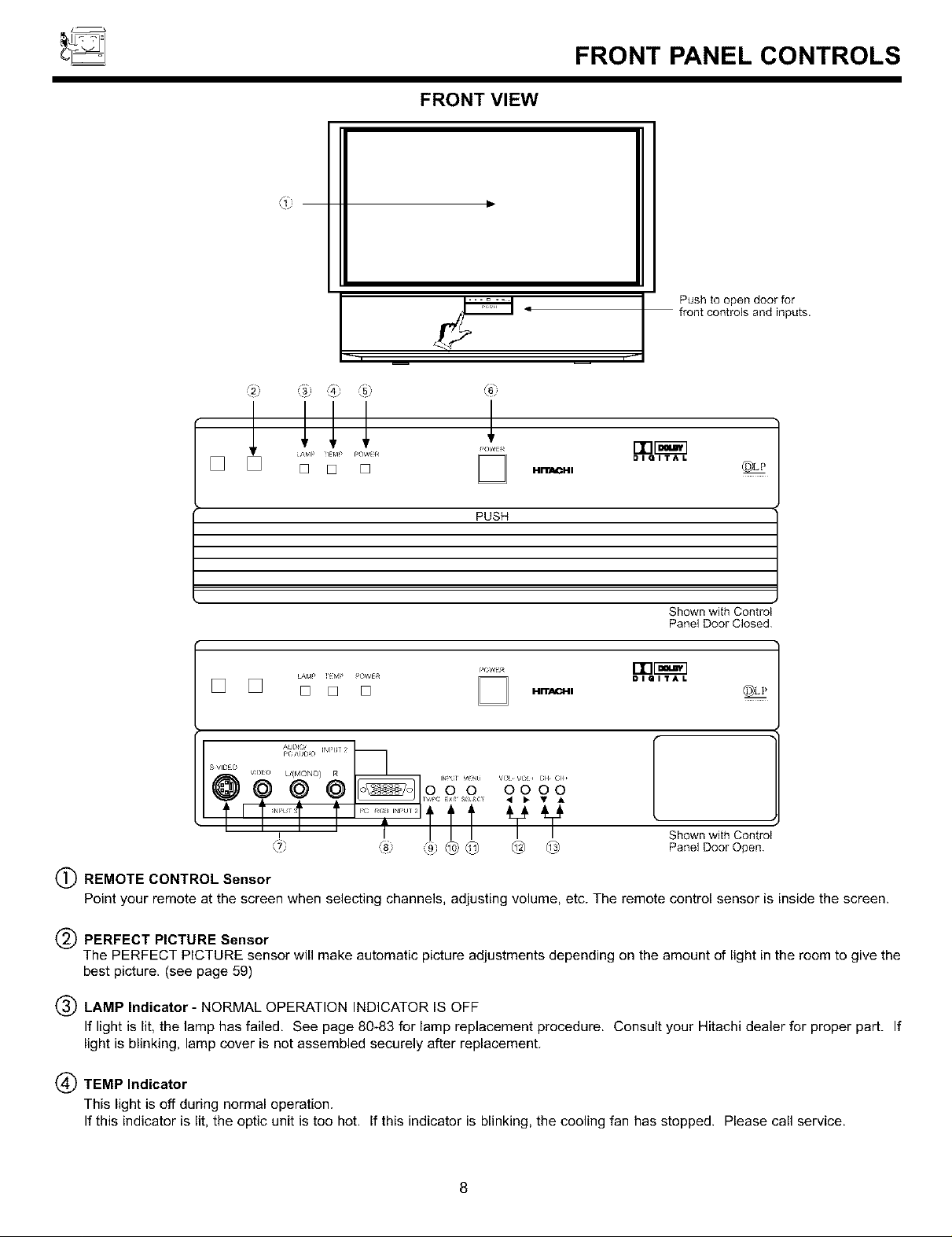
FRONT VIEW
4_
Push to open door for
front controls and inputs.
DIGITAL
PUSH
Shownwith Control
PanelDoorClosed
LAM' 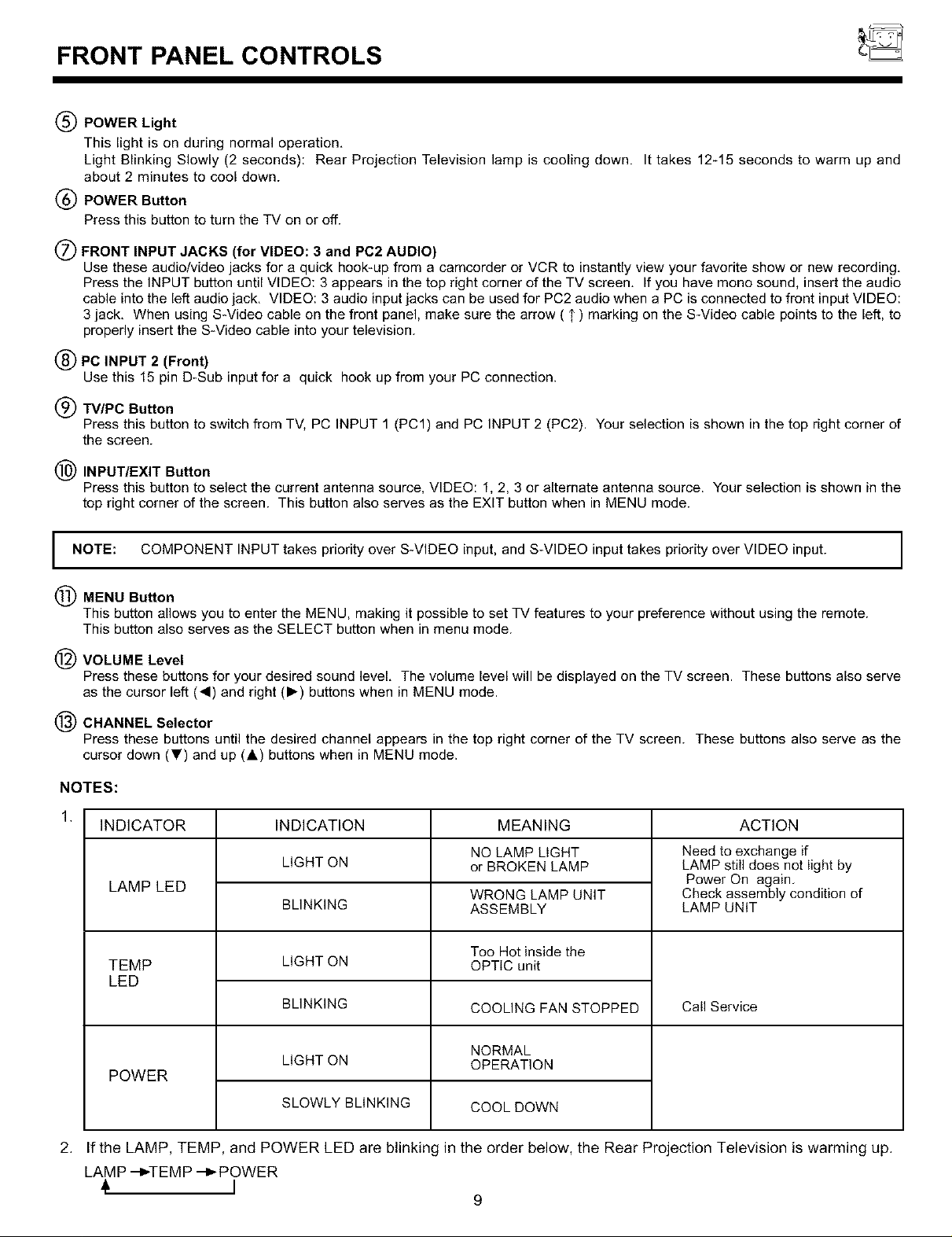
FRONT PANEL CONTROLS
(_ POWER Light
This light is on during normal operation,
Light Blinking Slowly (2 seconds): Rear Projection Television lamp is cooling down. It takes 12-15 seconds to warm up and
about 2 minutes to cool down.
POWER Button
Press this button to turn the TV on or off.
(_) FRONT INPUT JACKS (for VIDEO: 3 and PC2 AUDIO)
Use these audio/video jacks for a quick hook-up from a camcorder or VCR to instantly view your favorite show or new recording,
Press the INPUT button until VIDEO: 3 appears in the top right corner of the TV screen, If you have mono sound, insert the audio
cable into the left audio jack, VIDEO: 3 audio input jacks can be used for PC2 audio when a PC is connected to front input VIDEO:
3 jack, When using S-Video cable on the front panel, make sure the arrow ( 1') marking on the S-Video cable points to the left, to
properly insert the S-Video cable into your television.
(_PC INPUT 2 (Front)
Use this 15 pin D-Sub input for a quick hook up from your PC connection.
(_) FV/PC Button
Press this button to switch from TV, PC INPUT 1 (PC1) and PC INPUT 2 (PC2). Your selection is shown in the top right corner of
the screen.
(_) INPUT/EXIT Button
Press this button to select the current antenna source, VIDEO: 1, 2, 3 or alternate antenna source. Your selection is shown in the
top right corner of the screen. This button also serves as the EXIT button when in MENU mode.
NOTE: COMPONENT INPUT takes priority over S-VIDEO input, and S-VIDEO input takes priority over VIDEO input.
I
MENU Button
This button allows you to enter the MENU, making it possible to set TV features to your preference without using the remote.
This button also serves as the SELECT button when in menu mode.
VOLUME Level
Press these buttons for your desired sound level, The volume level will be displayed on the TV screen. These buttons also serve
as the cursor left (_1) and right (1_) buttons when in MENU mode.
CHANNEL Selector
Press these buttons until the desired channel appears in the top right corner of the TV screen. These buttons also serve as the
cursor down (_') and up (&) buttons when in MENU mode.
NOTES:
1,
INDICATOR ACTION
LAMP LED
TEMP
INDICATION
LIGHT ON
BLINKING
LIGHT ON
MEANING
NO LAMP LIGHT
or BROKEN LAMP
WRONG LAMP UNIT
ASSEMBLY
Too Hot inside the
OPTIC unit
Need to exchange if
LAMP still does not light by
Power On again.
Check assembly condition of
LAMP UNiT
LED
BLINKING
COOLING FAN STOPPED
Call Service
POWER
LIGHT ON
SLOWLY BLINKING
NORMAL
OPERATION
COOL DOWN
2. If the LAMP, TEMP, and POWER LED are blinking in the order below, the Rear Projection Television is warming up.
LAMP --_TEM P --_ POWER
I
9

FRONT PANEL JACKS AND CONNECTIONS
The front panel jacks are provided as a convenience to allow you to easily connect a VCR, PC or camcorder as shown in the
following examples:
.......
Audio Cable 41- RGB Cable
(Optiona (Optional)
NOTE:
NOTE:
Back of VCR
D-SUB 15 Pin
__ PC
Back of PC
S VHS Video Camera Output
Completely insert connection cord plugs when connecting to front panel jacks. If you do not, the played back picture may
be abnormal. If you have an S-VHS VCR, use the SqNPUT cable in place of the standard video cable. If you have a
mono VCR, insert the audio cable into the left audio jack of your TV. INPUT 3 audio can be used for PC INPUT 2 audio
when a PC INPUT 2 is connected.
Optional adapter for *Apple @ Macintosh @computers. If the optional AESP model G301/U Macintosh to VGA@ adapter
connector is configured and connected between Macintosh video out and the Rear Projection Television video in, the
Macintosh is forced to boot in 640 x 480/60 Hz or 800 x 600/60 Hz mode (set mode) because the operational adapter
correctly manipulates the Macintosh sense pins.
For the optional adapter to work, it s DIP switch settings should be # 2, 3, 6, 7 = ON and # 1, 4, 5, 8, 9, 10 = OFF.
See below: Example - See Switch Instructions for details.
Mode 5 = 2367 (SVGA 800 x 600/60 Hz configuration)
(VGA 640 x480/60 Hz configuration)
Composite Separate Sync
n[ ],
ON
23 67
1 45 8910
OFF
UI I U U
10
REAR PANEL JACKS
REAR VIEW
®
i
_i@I ©i
@
A_,_TA
CONVERTER
'>ol R:
rJ_ z I i,
t
O@ ® ®®
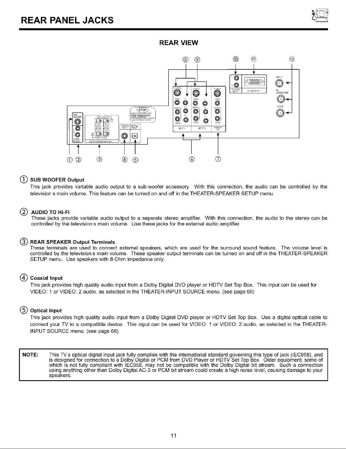
(_) SUB WOOFER Output
This jack provides variable audio output to a sub-woofer accessory. With this connection, the audio can be controlled by the
television s main volume. This feature can be turned on and off in the THEATER-SPEAKER SETUP menu.
AUDIO TO Hi-Fi
These jacks provide variable audio output to a seperate stereo amplifier. With this connection, the audio to the stereo can be
controlled by the television s main volume. Use these jacks for the external audio amplifier.
V
® @
REAR SPEAKER Output Terminals
These terminals are used to connect external speakers, which are used for the surround sound feature, The volume level is
controlled by the television s main volume. These speaker output terminals can be turned on and off in the THEATER-SPEAKER
SETUP menu. Use speakers with 8-Ohm impedance only.
(_ Coaxial Input
This jack provides high quality audio input from a Dolby Digital DVD player or HDTV Set Top Box. This input can be used for
VIDEO: 1 or VIDEO: 2 audio, as selected in the THEATER-INPUT SOURCE menu. (see page 66)
(_) Optical Input
This jack provides high quality audio input from a Dolby Digital DVD player or HDTV Set Top Box. Use a digital optical cable to
connect your TV to a compatible device. This input can be used for VIDEO: 1 or VIDEO: 2 audio, as selected in the THEATER-
INPUT SOURCE menu. (see page 66).
NOTE:
This TV s optical digital input jack fully complies with the international standard governing this type of jack (IEC958), and
is designed for connection to a Dolby Digital or PCM from DVD Player or HDTV Set Top Box. Older equipment, some of
which is not fully compliant with IEC958, may not be compatible with the Dolby Digital bit stream. Such a connection
using anything other than Dolby Digital AC-3 or PCM bit stream could create a high noise level, causing damage to your
speakers.
11

REAR PANEL JACKS
(_) AUDIO/VIDEO INPUTS 1, 2
The INPUT button on the front panel or Remote Control will step through each signal source input each time it is pressed. Use
the audio and video inputs to connect external devices, such as VCRs, camcorders, laserdisc players, DVD players etc. (If you
have mono sound, insert the audio cable into the left audio jack.)
NOTE: You may use VIDEO, S-VIDEO, or COMPONENT: Y-PBPR Inputs to connect to INPUT 1, 2. But note that only one of
these may be used at a time.
COMPONENT INPUT takes priority over S-VIDEO input and S-VIDEO input takes priority over VIDEO input.
MONITOR OUT
These jacks provide fixed audio and video signals which are used for recording. Use the S-VIDEO Output for high quality video
output. There is no MONITOR OUT when using COMPONENT VIDEO INPUT.
I NOTE: S-VIDEO Output may be used for recording, only when the input is of S-VIDEO type.
(_ S-VIDEO Inputs 1 and 2
Inputs 1 and 2 provide S-VIDEO (Super Video) jacks for connecting equipment with S-VIDEO output capability.
(_) COMPONENT VIDEO Y-PBPR INPUT
Y-PBPR jacks provide for connecting equipment with this capability, such as a DVD player.
NOTE:
PCAUDIO INPUT 1
Connect external devices for audio in PC mode. (see page 72)
PC INPUT 1
Use this 15-pin D-Sub Input for your PC connection. (see page 69)
DO NOT connect standard VIDEO or S-VIDEO when using Y-PBPR input.
Your component outputs may be labeled Y, B-Y, and R-Y. In this case, connect the components B-Y output to the TV s
PB input and the components R-Y output to the TV s PR input.
It may be necessary to adjust TINT or turn AUTO COLOR-ON to obtain optimum picture quality when using the
Y-PBPR inputs. (see pages 58 and 59)
To ensure no copyright infringement, the MONITOR OUT output will be abnormal, when using the Y-PBPR jacks.
When using the Y-PBPR jacks, Component Y-PBPR signal will be viewed as a blank PIP sub-picture. (see page 29)
ANTENNA Input/Output
The remote control allows you to switch between two separate 75-Ohm RF antenna inputs, ANT A and ANT B. ANT A input can be
displayed as a main picture or sub-picture. ANT B can only be displayed as a main picture. (ANT B cannot be displayed as a sub-
picture,) The antenna output labeled TO CONVERTER allows the ANT A connection to pass directly to a different source, such
as a cable box, only when ANT B is displayed as a main picture.
12
TIPS ON REAR PANEL CONNECTIONS
I NOTE: Turn off the Rear Projection Television and the PC before connecting or disconnecting any cables. J
TIPS ON REAR PANEL CONNECTIONS
S_VIDEO connections are provided for high performance laserdisc players, VCRs etc. that have this feature. Use these connections
in place of the standard video connection if your device has this feature.
If your device has only one audio output (mono sound), connect it to the left audio jack on the television.
Refer to the operating guide of your other electronic equipment for additional information on connecting your hook-up cables.
A single VCR can be used for VCR#1 and VCR#2, but note that a VCR cannot record its own video or line output. (INPUT 1 in
example on page 14) Refer to your VCR operating guide for more information on line input-output connection.
You may use VIDEO, S_VlDEO, or COMPONENT: Y-PBPR inputs, but note that only one of these may be used at a time.
Connect only 1 component to each input jack.
COMPONENT: Y-PBPR connections are provided for high performance components, such as DVD players. Use these connections
in place of the standard video connection if your device has this feature.
When using the Y_PBPR input jacks, connect your components audio output to the TV s Left and Right audio input jacks.
/
Your component outputs may be labeled Y, B-Y, and R_Y. In this case, connect the components B-Y output to the TV s PB input and
the components R_Y output to the TV s PR input.
It may be necessary to adjust TINT or turn AUTO COLOR-ON to obtain optimum picture quality when using the
Y-PBPR inputs. (see pages 58 and 59)
To ensure no copyright infringement, the MONITOR OUT output will be abnormal, when using the Y-PBPR jacks.
13

_ REAR PANELJACKS
TYPICAL FULL-FEATURE SETUP
Outside antenrla or
came TV coaxial cable _ _
2=Way signal spl_O
Surround Speakers
-y÷ v +,_
Sub Woofer
connecllons
on page 17
VCR#1 DVDPlayer
•--_ °6 o.To,
B _gEO V L
@@@
I
I
I
I
Optional,seetips _J
on page13_,
pB/c _ P_/CR L
[ ouzPu_S]
@@@
lllll
L IJ,_lJ
I
I
I
I
I
I'T
"-_-i
TO
Cable TV Box
on page 13
too°I. .[ ooo,]
S VIDEOV L OTPUTL OUTPUT -OR- y_ pB pR
Laserdiscplayer,VCR, HDTVSet-TopBox
camcorder,etc.
NOTES: 1. Connect only 1 component to each input jack.
2. Follow connections that pertain to your personal entertainment system.
14
VCR#2
RGB •
OUTPUT
0
©
REAR SPEAKER TERMINAL CONNECTIONS
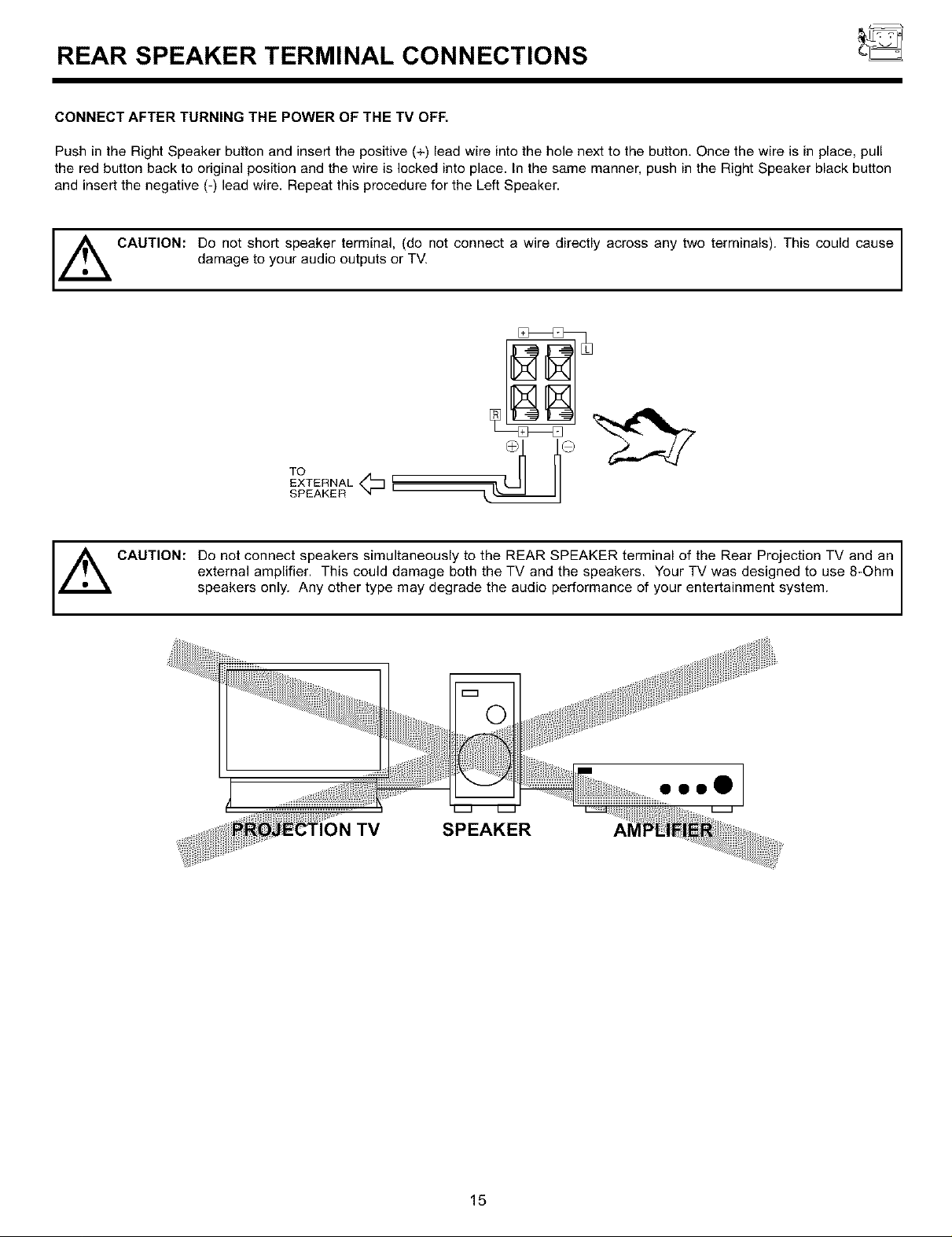
CONNECT AFTER TURNING THE POWER OF THE TV OFF.
Push in the Right Speaker button and insert the positive (+) lead wire into the hole next to the button. Once the wire is in place, pull
the red button back to original position and the wire is locked into place. In the same manner, push in the Right Speaker black button
and insert the negative (-) lead wire. Repeat this procedure for the Left Speaker.
,_ CAUTION: Do not short speaker terminal, (do not connect a wire directly across any two terminals). This could cause
,_ CAUTION: Do not connect speakers simultaneously to the REAR SPEAKER terminal of the Rear Projection TV and an
damage to your audio outputs or TV.
TO
EXTERNAL<_ I
SPEAKER I
external amplifier. This could damage both the TV and the speakers. Your TV was designed to use 8-Ohm
speakers only. Any other type may degrade the audio performance of your entertainment system.
m
)N TV SPEAKER
15
oooO

CONNECTING EXTERNAL AUDIO SOURCES
CONNECTING EXTERNAL AUDIO AMPLIFIER
To control the audio level of an external audio amplifier with the remote control, connect the system as shown below.
REAR PANEL OF TELEVISION
ANTA
@O
L R
INPUT
_=
To Audio Input Terminal
of External Amplifier
O _ O
[EE] [EE] ©©
© miRiammiRiam©
_ D
Stereo System Amplifier
s V_EO
@
_0
INp T_
SV_0E0
@
SO
tJc_J°_ _O
'dON=TO_
O,JT
TO
CONVERTER
ANT
NOTE: To prevent damage to the speaker and distorted sound, set the volume control of the audio amplifier lower and adjust
the sound using the remote control of the TV set.
16

AUDIO SYSTEM SETUP
Match the numbers below to the diagrams for speaker placement and refer to the table on page 18 for the different surround sound
requirements. (See page 63 and 64 for SURROUND functions.)
(_) The television s internal speakers.
The television s internal center channel speaker, which is on only when the television is in SURROUND-STADIUM, SURROUND-
ROCK ARENA, SURROUND-JAZZ CLUB, SURROUND-PRO LOGIC, or SURROUND-DOLBY DIGITAL mode.
(_ These speakers are connected to a separate audio amplifier. Use the AUDIO TO HI-FI output on the TV.
(_ These speakers are connected to a rear speaker 8-Ohm output on the TV.
(_) This sub woofer is connected to the SUB WOOFER output on the TV.
J
__[_ [
®
O
©
(_) IN
©
SUB WOOFER
©o©
IN OUT
STEREO SYSTEM (r_
l L R L R
AMPLIFIER
®
O
LS
17

AUDIO SYSTEM SETUP
SURROUND REQUIRED OPTIONAL EFFECT
FEATURE CONNECTION CONNECTION
OFF _ _3__S_ Receive mono and stereo sound.
STADIUM _3__S_ Listener has feeling of being at a stadium.
ROCK ARENA _ _2__4_ _3__S_ Listener has feeling of being at a rock concert.
JAZZ CLUB _3__S_ Listener has feeling of being at a jazz club.
DOLBY (3__S_ Movie theater reproduction, with separate left,
PRO LOGIC center, right, and surround channels.
DOLBY DIGITAL _ _2__4__S_ To be used with a DVD player or HDTV Set Top
Box with Dolby Digital output. This provides up to
6 channels of all-digital surround sound. There are
3 full-range channels for the front (FL, C, FR) plus
separate, full-range left and right surround
channels (SL, SR). The sixth channel is Low
Frequency Effects for a sub woofer (SW),
supplying those room-shaking rumbles
experienced in the best movie theaters.
When left and right speakers are connected (_3_), the internal speakers (_) can be disabled, creating better separation between left, center and right
channels. The center channel audio will be heard from (_2_),this speaker cannot be disabled.
18

CONNECTING EXTERNAL VIDEO SOURCES
The exact arrangement you use to connect the VCR, camcorder, laserdisc player, and DVD player to your TV set is dependent on the
model and features of each component. Check the owner s manual of each component for the location of video and audio inputs and
outputs.
The following connection diagrams are offered as suggestions. However, you may need to modify them to accommodate your particular
assortment of components and features. For best performance, video and audio cables should be made from coaxial shielded wire.
Before Operating External Video Source
The input mode is changed every time the INPUT button on the Front Panel or the Remote Control is pressed as shown below. Connect
an external source to the INPUT terminals, then press the INPUT button as necessary to view the input source. (See page 27)
INPUT MODE SELECTION ORDER
(INPUT)
12
VIDEO:l] INPUT
(INPUT)
VIDEO:2 INPUT
(INPUT)
-- 0---'
INPUTo ANT B 32 q INPUTo
NOTE: When the Rear Projection TV is set to VIDEO and a video signal is not received from the VIDEO INPUT jack on the back
panel of the Rear Projection TV (i.e., VCRllaserdisc player, etc. is not connected or the video device is OFF), the TV set
will appear to be OFF.
CONNECTING A MONAURAL AUDIO VCR OR LASERDISC PLAYER
1. Connect the cable from the VIDEO OUT of the VCR or the laserdisc player to the INPUT (VIDEO) jack on the TV set below.
2. Connect the cable from the AUDIO OUT of the VCR or the laserdisc player to the INPUT (MONO)tL(AUDIO) jack.
3. Press the INPUT button on the Front Panel or Remote Control to view the program from the VCR or the laserdisc player. The VIDEO
icon disappears automatically after approximately eight seconds.
4. Press the INPUT button to return to the previous channel.
RearPanelofTelevision
VIDEO:3
ANTA
©
TO
@ @ ............
@ @ ©
oi ©
CO_VER_ER
@@
VCR
HitachiModelor
SimilarModel
NRjT _or,l
19
__ CONNECTING EXTERNAL VIDEO SOURCES
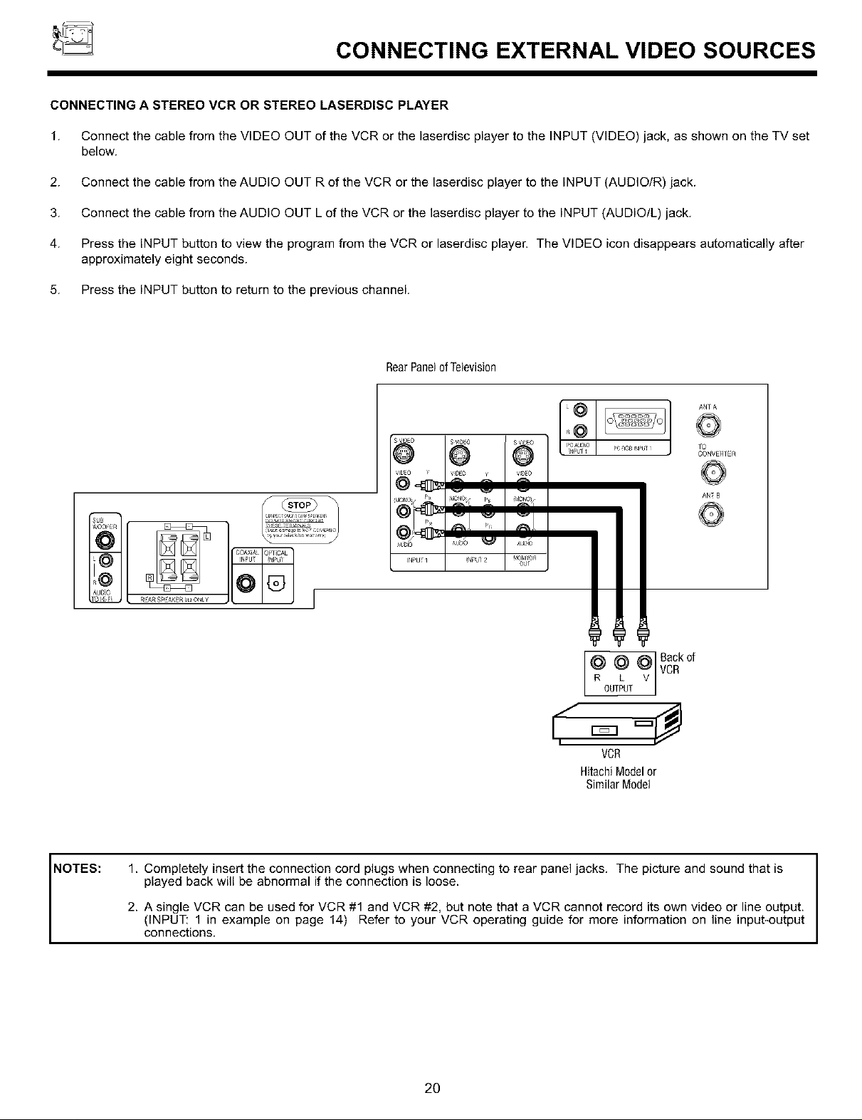
CONNECTING A STEREO VCR OR STEREO LASERDISC PLAYER
1. Connect the cable from the VIDEO OUT of the VCR or the laserdisc player to the INPUT (VIDEO) jack, as shown on the TV set
below.
2. Connect the cable from the AUDIO OUT R of the VCR or the laserdisc player to the INPUT (AUDIOIR) jack.
3. Connect the cable from the AUDIO OUT L of the VCR or the laserdisc player to the INPUT (AUDIO/L) jack.
4. Press the INPUT button to view the program from the VCR or laserdisc player. The VIDEO icon disappears automatically after
approximately eight seconds.
5. Press the INPUT button to return to the previous channel.
RearPanelofTelevision
0
S VIDEO SVIDEO SVrSEO
@ @ @
pC_GBINF>UT_ TO
CONVERTER
ANTB
,- 2_[
Ab_lO AU_a _ Aur,l_
INPUI ] NPU 2 MOtIrOR
_EA_ gPEAKER_ ON_¥
Od
¢ ¢ ¢]v%k0'
R00,P ,v]
VCR
HitachiModelor
SimilarModel
1. Completely insert the connection cord plugs when connecting to rear panel jacks. The picture and sound that is
played back will be abnormal if the connection is loose.
NOTES:
2. A single VCR can be used for VCR #1 and VCR #2, but note that a VCR cannot record its own video or line output.
(INPUT: 1 in example on page 14) Refer to your VCR operating guide for more information on line input-output
connections.
2O

CONNECTING EXTERNAL VIDEO SOURCES
CONNECTING AN S-VIDEO VCR OR LASERDISC PLAYER
1. Connect the cable from the S-VIDEO OUT of the VCR or the laserdisc player to the INPUT (S-VIDEO) jack, as shown on the
TV set below.
2. Connect the cable from the AUDIO OUT R of the VCR or the laserdisc player to the INPUT (AUDIO/R) jack.
3. Connect the cable from the AUDIO OUT L of the VCR or the laserdisc player to the INPUT (AUDIO/L) jack.
4. Press the INPUT button to view the program from the VCR or laserdisc player. The VIDEO icon disappears automatically after
approximately eight seconds.
5. Press the INPUT button to retum to the previous channel.
RearPanelofTelevision
Aq_
sv_o SwoEo I 3WDEO
V_OEO _ vr3EO ¥ I V_OEO
@@ @ @1@
_r_l_ ......
AUDIO Aur,l_ _ I ,_l_'#_
Seetips on,_
Page13 _
L V S VIDE[
OUTPUT
VCRor LaserdiscPlayer
HitachiModelor
SimilarModel
r0
CONVERTER
ANTB
BackofVCRor
LaserdiscPlayer
NOTES:
1. Completely insert the connection cord plugs when connecting to rear panel jacks. The picture and sound that is
played back will be abnormal if the connection is loose.
2. A single VCR can be used for VCR #1 and VCR #2, but note that a VCR cannot record its own video or line output.
(INPUT: 1 in example on page 14) Refer to your VCR operating guide for more information on line input-
output connections.
21
CONNECTING EXTERNAL VIDEO SOURCES
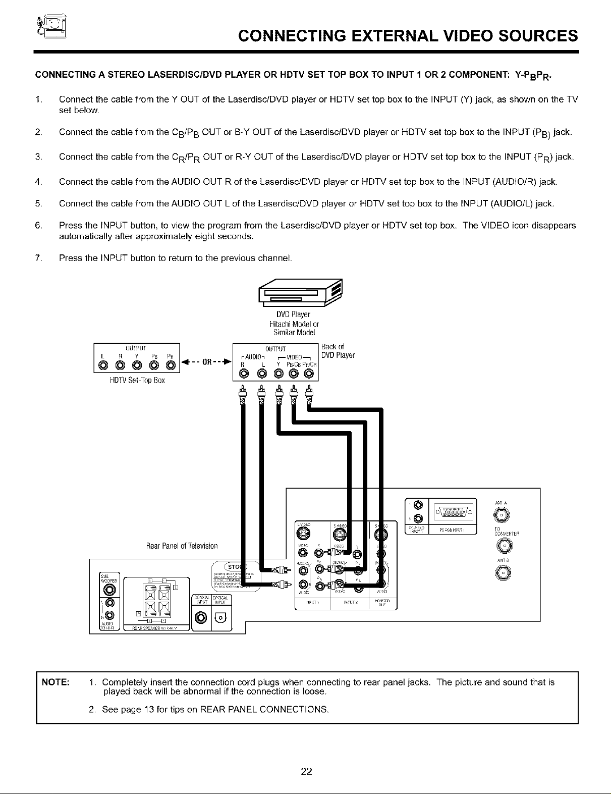
CONNECTING A STEREO LASERDISC/DVD PLAYER OR HDTV SET TOP BOX TO INPUT 1 OR 2 COMPONENT: Y-PBPR .
1. Connect the cable from the Y OUT of the LaserdisclDVD player or HDTV set top box to the INPUT (Y) jack, as shown on the TV
set below.
2. Connect the cable from the CB/P B OUT or B-Y OUT of the LaserdisclDVD player or HDTV set top box to the INPUT (PB) jack.
3. Connect the cable from the CR/P R OUT or R-Y OUT of the Laserdisc/DVD player or HDTV set top box to the INPUT (PR) jack.
4. Connect the cable from the AUDIO OUT R of the LaserdisclDVD player or HDTV set top box to the INPUT (AUDIO/R) jack.
5. Connect the cable from the AUDIO OUT L of the LaserdisclDVD player or HDTV set top box to the INPUT (AUDIO/L) jack.
6. Press the INPUT button, to view the program from the Laserdisc/DVD player or HDTV set top box. The VIDEO icon disappears
automatically after approximately eight seconds.
7. Press the INPUT button to return to the previous channel.
DVDPlayer
HitachiModelor
SimilarModel
R Y PB r AUDIOn r--VIDEO_
@ @ @ 4---oB---_- R L Y PB,,CBPoJC_
5 00,POT o0,P0, avC%e'
HDTVSet-T0pB0x @ @ _ @ @
@
RearPanelofTelevision
R ARSP #_ R_ _N¥
@ @4
AN1 A
i'O
CONVERTER
AN1
NOTE: 1. Completely insert the connection cord plugs when connecting to rear panel jacks. The picture and sound that is
played back will be abnormal if the connection is loose.
2. See page 13 for tips on REAR PANEL CONNECTIONS.
22
CONNECTING EXTERNAL VIDEO SOURCES
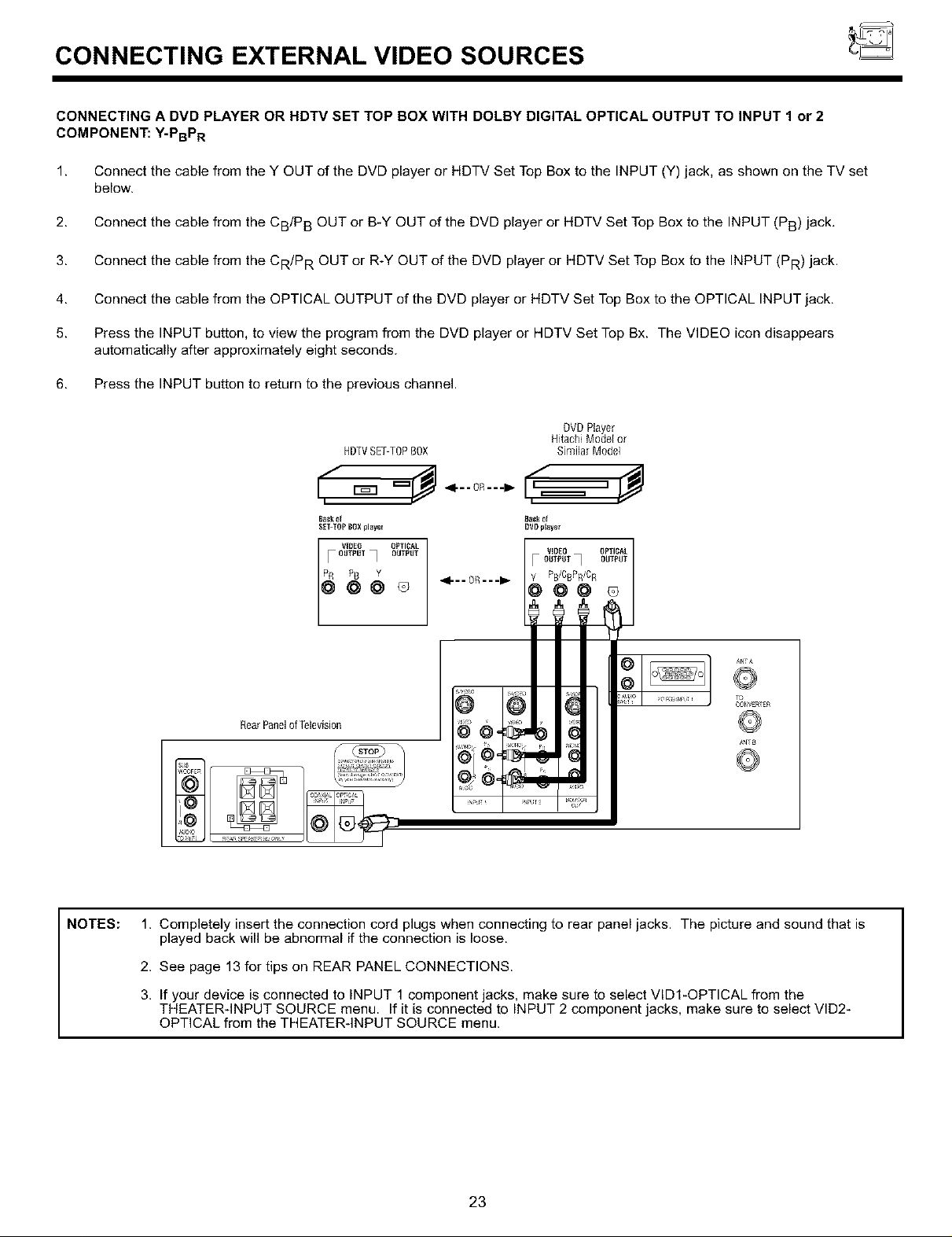
CONNECTING A DVD PLAYER OR HDTV SET TOP BOX WITH DOLBY DIGITAL OPTICAL OUTPUT TO INPUT 1 or 2
COMPONENT: Y-PBPR
1. Connect the cable from the Y OUT of the DVD player or HDTV Set Top Box to the INPUT (Y) jack, as shown on the TV set
below.
2. Connect the cable from the CB/P B OUT or B-Y OUT of the DVD player or HDTV Set Top Box to the INPUT (PB) jack.
3. Connect the cable from the CR/P R OUT or R-Y OUT of the DVD player or HDTV Set Top Box to the INPUT (PR) jack.
4. Connect the cable from the OPTICAL OUTPUT of the DVD player or HDTV Set Top Box to the OPTICAL INPUT jack.
5. Press the INPUT button, to view the program from the DVD player or HDTV Set Top Bx. The VIDEO icon disappears
automatically after approximately eight seconds.
6. Press the INPUT button to return to the previous channel.
HDTVSET-TOPBOX
NOTES:
SEI-10p BOX player
F OUTPUT_ OUTPUT
VIOEO OP_fI_L
[ggo
ANTA
@
TO
CO_V£RTER
RearPanelof Television
1. Completely insert the connection cord plugs when connecting to rear panel jacks. The picture and sound that is
played back will be abnormal if the connection is loose.
2. See page 13 for tips on REAR PANEL CONNECTIONS.
3. If your device is connected to INPUT 1 component jacks, make sure to select VID1-OPTICAL from the
THEATERqNPUT SOURCE menu. If it is connected to INPUT 2 component jacks, make sure to select VlD2-
OPTICAL from the THEATERqNPUT SOURCE menu.
23

CONNECTING EXTERNAL VIDEO SOURCE
CONNECTING A DVD PLAYER OR HDTV SET TOP BOX WITH DOLBY DIGITAL COAXIAL OUTPUT TO INPUT
COMPONENT: Y-PBPR
1. Connect the cable from the Y OUT of the DVD player or HDTV Set Top Box to the INPUT (Y) jack, as shown on the TV set
below.
2. Connect the cable from the CB/P B OUT or B-Y OUT of the DVD player or HDTV Set Top Box to the INPUT (PB) jack.
3. Connect the cable from the CR/P R OUT or R-Y OUT of the DVD player or HDTV Set Top Box to the INPUT (PR) jack.
4. Connect the cable from the COAXIAL OUTPUT of the DVD player or HDTV Set Top Box to the COAXIAL INPUT jack.
5. Press the INPUT button, to view the program from the DVD player or HDTV Set Top Box. The VIDEO icon disappears
automatically after approximately eight seconds.
6. Press the INPUT button to return to the previous channel.
DVDPlayer
HDTVSET-TOPBOX
HitachiModel or
Similar Model
NOTE:
_1"- - OR- - -II_ _m_ ]
Ba_k ef
$_T-TOp BOX_lay_r
_ OUTPUT COAXIAL
Rear Panelof Television
VIDe0 _ OUTPUT
@@
4 - - OR- - -I_ Y CB OR
Back 0f
DV# player
OUTPUT
@@@
VIOE0 _0_L
_o
O_VERT£R
A_TB
©
J
1. Completely insert the connection cord plugs when connecting to rear panel jacks. The picture and sound that is
played back will be abnormal if the connection is loose.
2. See page 13 for tips on REAR PANEL CONNECTIONS.
3. If your device is connected to INPUT 1 component jacks, make sure to select VIDI-COAXlAL (DIGITAL) from
the THEATERqNPUT SOURCE menu. If it is connected to INPUT 2 component jacks, make sure to select
VID2-COAXlAL (DIGITAL) from the THEATERqNPUT SOURCE menu.
24

THE GENIUS REMOTE CONTROL
In addition to controlling all the functions on your HITACHI Projection TV, the new remote control is designed to operate different
types of VCRs, CATV (Cable TV) converters, satellite receivers, DVD players, and other audio/video equipment with one touch.
Basic operation keys are grouped together in one area.
To operate your TV, point the remote control at the remote sensor of the TV and press the TV button. The TV button will blink,
indicating that the remote will now control your television.
To operate your VCR, point the remote at the remote sensor of the VCR and press the VCR button. The VCR button will blink,
indicating that the remote will now control your VCR. (See page 32 for instructions on how to program the remote to control your
VCR.)
To operate your cable box, point the remote at the remote sensor of the cable box and press the CABLE (CBL) button. The CBL
button will blink, indicating that the remote will now control your cable box. (See page 33 for instructions on how to program the
remote to control your cable box.)
To operate your satellite receiver, point the remote at the remote sensor of the satellite receiver and press the SATELLITE (SAT)
button. The SAT button will blink, indicating that the remote will now control your satellite receiver. (See page 34 for instructions
on how to program the remote to control your satellite receiver.)
To operate your DVD player, point the remote at the remote sensor of the DVD player and press the DVD button. The DVD button
will blink, indicating that the remote will now control your DVD player. (See page 35 for instruction on how to program the remote
to control your DVD player.)
J
To operate additional audio/video equipment, point the remote at the remote sensor of the component you wish to control and
press the AVl, AV2 or AV3 button. This button will blink, indicating that the remote will now control the desired component. (See
page 36 for instructions on how to program the remote to control additional Audio/Video equipment.)
r6--@Z97G=
1® "®%1
f®--®--®]
(_ These buttons allow the remote to control your TV, VCR,
cable box, satellite receiver, DVD player, or other
AudiolVideo equipment depending on which mode is
chosen, as explained above.
]® Q (i)]
I iI -(_
,,®® ®,,
dP_LQ,_O_j......
(_),(_) LIGHT BUTTON
When you are in a dark room, press the light button (_)
on the remote to light up the buttons shown in (_ and the
source button will blink. Thelight will stay on for about 8
seconds if the light button is not pressed again. These
buttons will not appear to light if the room is too bright.
@-
6© d
o o o
L0j ®]-¢
25
HOW TO USE THE GENIUS REMOTE TO CONTROL YOUR TV
0(2 ®
REC
HITACHI
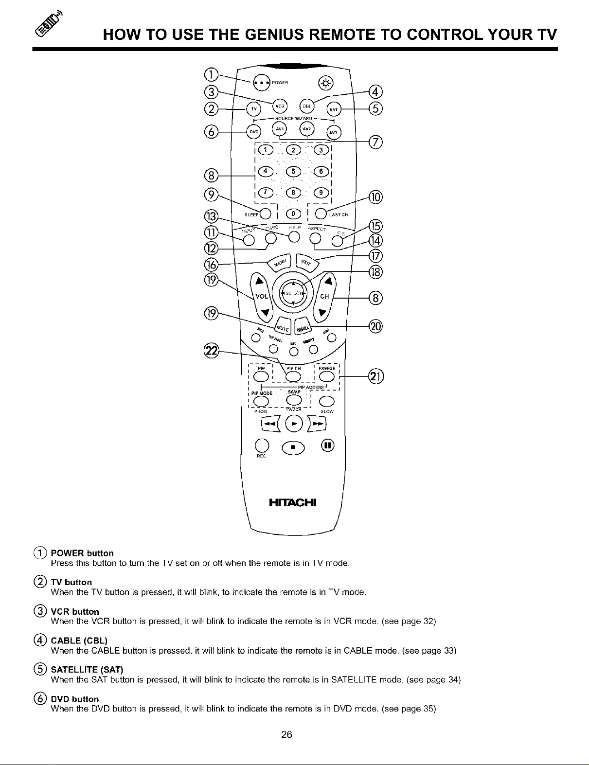
(_ POWER button
Press this button to turn the TV set on or off when the remote is in TV mode.
(_)TV button
When the TV button is pressed, it will blink, to indicate the remote is in TV mode.
(_) VCR button
When the VCR button is pressed, it will blink to indicate the remote is in VCR mode. (see page 32)
(_ CABLE (CBL)
When the CABLE button is pressed, it will blink to indicate the remote is in CABLE mode. (see page 33)
(_ SATELLITE (SAT)
When the SAT button is pressed, it will blink to indicate the remote is in SATELLITE mode. (see page 34)
(_) DVD button
When the DVD button is pressed, it will blink to indicate the remote is in DVD mode. (see page 35)
26

HOW TO USE THE GENIUS REMOTE TO CONTROL YOUR TV
(_ AM1, AV2, AM3 buttons
When pressed, each of these buttons will blink to indicate the remote is inAudiolVideo mode. (see page 36)
(_ CHANNEL selector buttons
CHANNEL selector buttons are used to set FAMILY FAVORITES, CHANNEL MEMORY, etc,
Enter one, two, or three numbers to select channels. Enter 0 first for channels 1 to 9, or simply press the single digit channel you
wish to tune then wait a few seconds for the TV to tune, For channels 100 and above, press the 1 button, wait until two dashes
appear next to the channel display on your TV, then enter the remaining two numbers using the number buttons.
Channel selection may also be performed by pressing CH up (A) or down (T).
You can also use these number buttons to directly access OSD sub-menu s of your choice. While navigating the On-Screen-
Display s, you will notice that each sub-menu has a number next to it, For example, the SET UP menu has 9 sub-menu s. Pressing
the (_) button while in the SET UP menu will take you directly to the CLOCK SET sub-menu, This makes navigating the menu s
faster and easier.
I NOTE: The TV may not receive some channels if you are not in the correct SIGNAL SOURCE mode. (see page 42) I
(_) SLEEP button
Press this button to display the sleep timer in the lower left corner of the screen. Every subsequent press of this button will add 15
minutes to this timer, up to a maximum of three hours. Once set, use RECALL when you want to view time remaining. If the SLEEP
button is pressed while the timer is set, it will reset to the original condition.
LAST CHANNEL (LAST CH) button
Use this button to select between the last two channels viewed. (Good for watching two sporting events, etc.)
ANT A 39
LAST CH
0
INPUT button
The INPUT button will select between both antenna signals and the three sets of video input jacks each time the button is pressed.
If the Picture-in-Picture is on, the INPUT button will select between the three sets of video input jacks and both antenna sources
when main channel is chosen with the PIP CH button. If the sub-picture is chosen, the INPUT button will select between the three
sets of video input jacks and the ANT A antenna source (ANT B source cannot be displayed as a PiP sub-picture),
INPUT
INPUT
INPUT
INPUT
TV/PC buffon
Pressthisbuttonteswitch between TV, PCl(PCINPUT1)and PC2(PCINPUT2) modes.
HELP button
Press this button when a menu is displayed to view HELP text, which gives a description of the displayed menu. The HELP text
will be displayed every time a MENU is displayed, until this button is pressed again.
27
HOW TO USE THE GENIUS REMOTE TO CONTROL YOUR TV
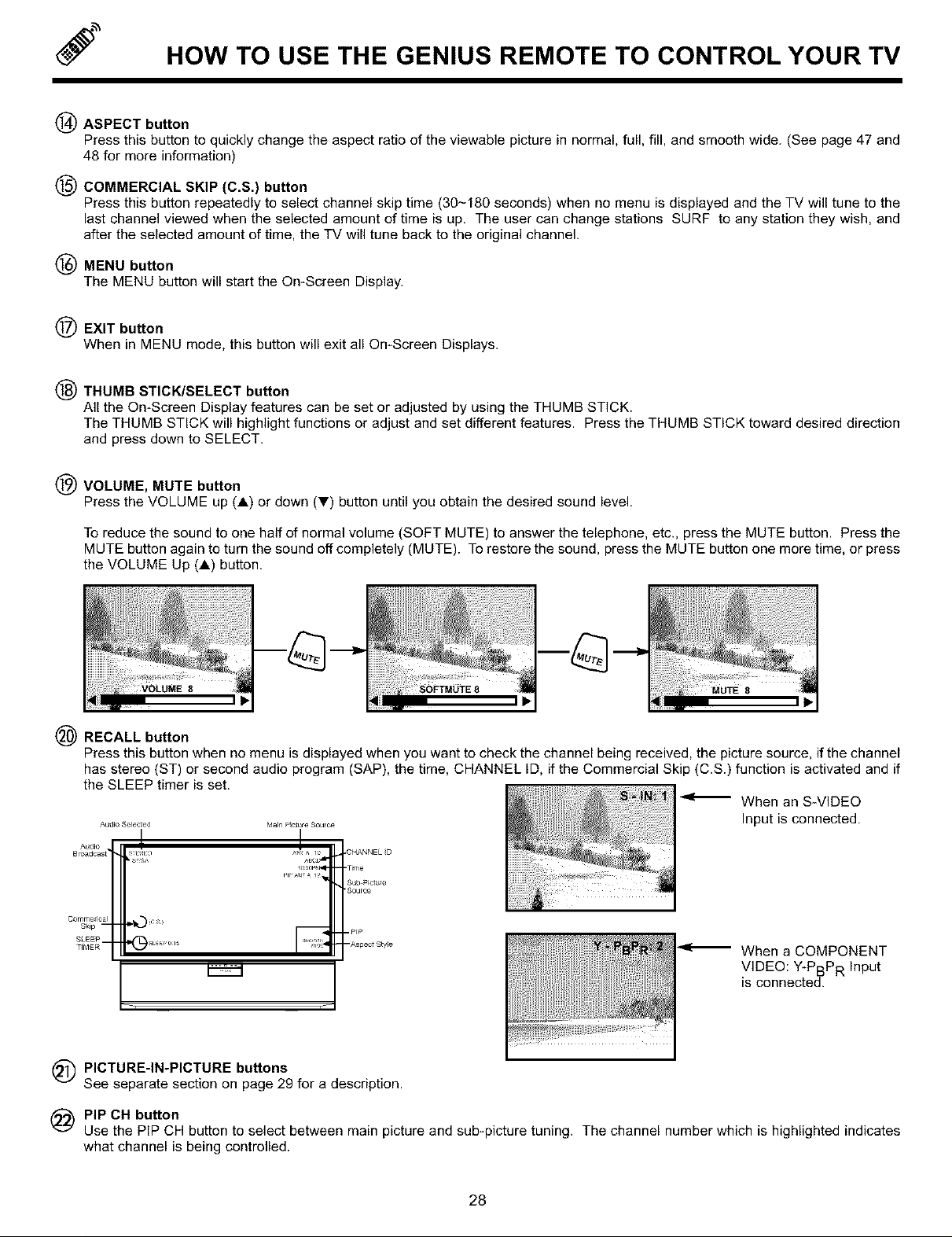
(_) ASPECT button
Press this button to quickly change the aspect ratio of the viewable picture in normal, full, fill, and smooth wide. (See page 47 and
48 for more information)
(_ COMMERCIAL SKIP (C.S.) button
Press this button repeatedly to select channel skip time (30-180 seconds) when no menu is displayed and the TV will tune to the
last channel viewed when the selected amount of time is up, The user can change stations SURF to any station they wish, and
after the selected amount of time, the TV will tune back to the original channel.
(_ MENU button
The MENU button will start the On-Screen Display.
EXIT button
When in MENU mode, this button will exit all On-Screen Displays.
(_) THUMB STICK/SELECT button
All the On-Screen Display features can be set or adjusted by using the THUMB STICK.
The THUMB STICK will highlight functions or adjust and set different features. Press the THUMB STICK toward desired direction
and press down to SELECT.
VOLUME, MUTE button
Press the VOLUME up (A) or down (_') button until you obtain the desired sound level.
To reduce the sound to one half of normal volume (SOFT MUTE) to answer the telephone, etc., press the MUTE button. Press the
MUTE button again to turn the sound off completely (MUTE). To restore the sound, press the MUTE button one more time, or press
the VOLUME Up (A) button.
8
(_ RECALL button
Press this button when no menu is displayed when you want to check the channel being received, the picture source, if the channel
has stereo (ST) or second audio program (SAP), the time, CHANNEL ID, if the Commercial Skip (C.S.) function is activated and if
the SLEEP timer is set.
When an S-VIDEO
Audio SeleCted
Audio • I
BrCadCast f-_o
Co rnrne_ical 1,410 (C __
S_ip --
SLEEP--T_,_E R I_ sL_E_'0_ls
M_Po_o_soo_e Input is connected.
,CHANNEL _D
-Time
Sub.picluTe
'Source
-pIp
--Aspect S_yle
When a COMPONENT
VIDEO: Y-PBPR Input
is connected.
i
(_ PICTURE-IN-PICTURE buttons
See separate section on page 29 for a description.
PIP CH button
Use the PIP CH button to select between main picture and sub-picture tuning. The channel number which is highlighted indicates
what channel is being controlled.
28
 Loading...