

Hitachi 61SBX59B, 53SBX59B Owner’s Manual
PROJECTION COLOR TV
OPERATING GUIDE
IMPORTANT SAFEGUARDS
FIRST TIME USE
THE GENIUS
REMOTE CONTROL
ULTRATEC BIT-MAP
ON-SCREEN DISPLAY
2-4
5-21
22-33
34-64
,_'_ ASK
v_
USEFUL INFORMATION INDEX 65-69
Follow all warnings and instructions marked on this projection television.
IMPORTANT
WARNING
RISK OF ELECTRIC SHOCK
DO NOT OPEN
CAUTION: TO REDUCE THE RISK OF ELECTRIC SHOCK,
DO NOT REMOVE COVER (OR BACK).
NO USER SERVICEABLE PARTS INSIDE.
REFER SERViCiNG TO QUALIFIED SERVICE PERSONNEL.
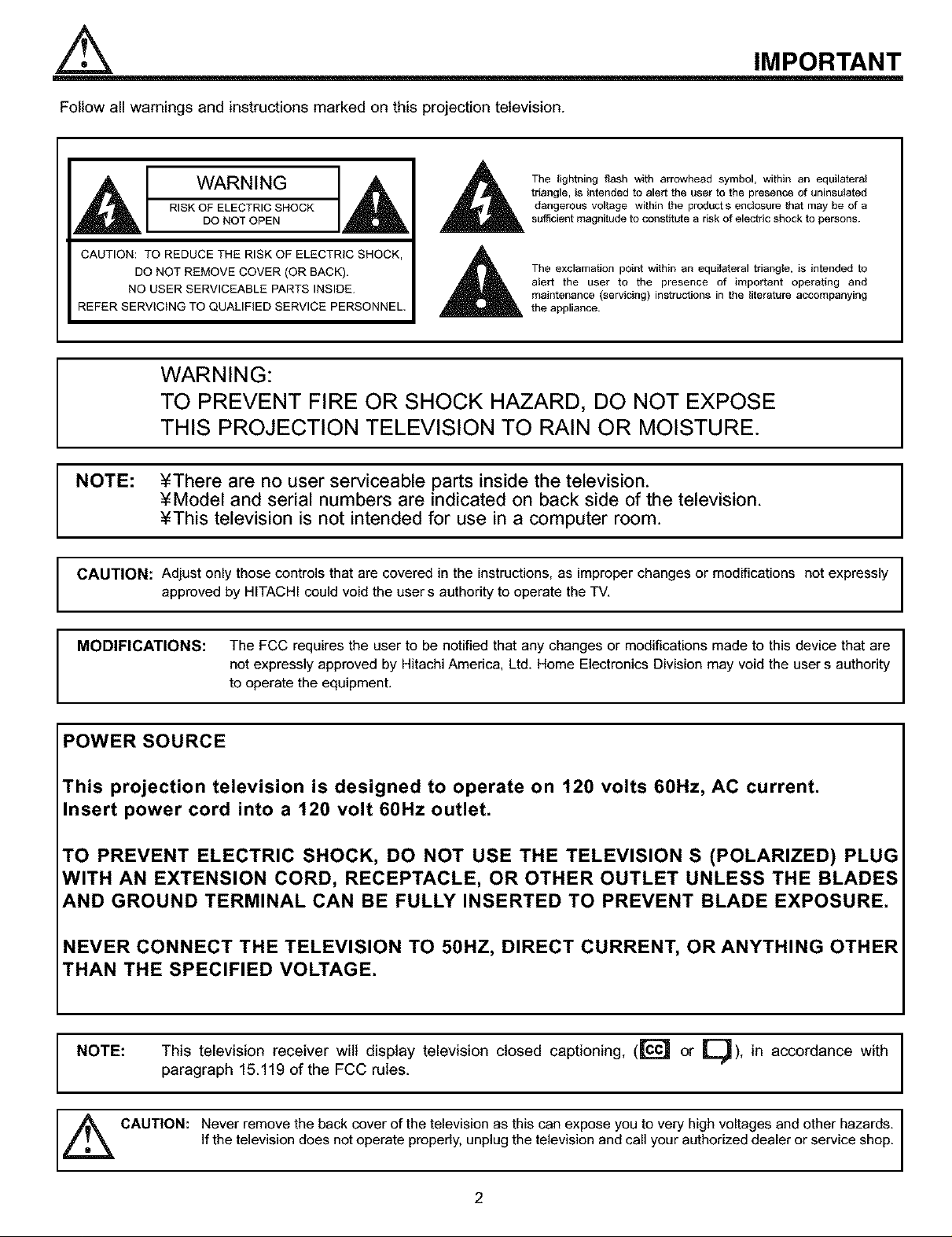
The lightning flash with arrowhead symbol, within an equilateral
triangle, is intended to alert the user to the presence of uninsulated
dangerous voltage within the products enclosure that may be of a
sufficient magnitude to constitute a risk of electric shock to persons.
The exclamation point within an equilateral triangle, is intended to
alert the user to the presence of important operating and
maintenance (servicing) instructions in the literature accompanying
the appliance.
TO PREVENT FIRE OR SHOCK HAZARD, DO NOT EXPOSE
WARNING: I
THIS PROJECTION TELEVISION TO RAIN OR MOISTURE.
NOTE: ¥There are no user serviceable parts inside the television. I
¥Model and serial numbers are indicated on back side of the television.
¥This television is not intended for use in a computer room.
CAUTION: Adjust only those controls that are covered in the instructions, as improper changes or modifications not expressly I
approved by HITACHI could void the user s authority to operate the TV.
I
I
MODIFICATIONS: The FCC requires the user to be notified that any changes or modifications made to this device that are
not expressly approved by Hitachi America. Ltd. Home Electronics Division may void the user s authority
to operate the equipment.
POWER SOURCE
This projection television is designed to operate on 120 volts 60Hz, AC current.
Insert power cord into a 120 volt 60Hz outlet.
TO PREVENT ELECTRIC SHOCK, DO NOT USE THE TELEVISION S (POLARIZED) PLUG
WITH AN EXTENSION CORD, RECEPTACLE, OR OTHER OUTLET UNLESS THE BLADES
AND GROUND TERMINAL CAN BE FULLY INSERTED TO PREVENT BLADE EXPOSURE.
NEVER CONNECT THE TELEVISION TO 50HZ, DIRECT CURRENT, OR ANYTHING OTHER
THAN THE SPECIFIED VOLTAGE.
NOTE: This television receiver wilt display television closed captioning, ([c'_ or [_), in accordance with I
paragraph 15.119 of the FCC rules.
I
,_ CAUTION: Never remove the back cover of the television as this can expose you to very high voltages and other hazards. I
If the television does not operate properly, unplug the television and call your authorized dealer or service shop.
2
SAFETY TIPS
IMPORTANT SAFEGUARDS
CAUTION: ¥ Read all of these instructions,
¥ Save these instructions for later use,
SAFETY POINTS YOU SHOULD KNOW ABOUT
YOUR HITACHI PROJECTION TELEVISION
¥ Follow all warnings and instructions marked
on the television.
Our reputation has been built on the quality, performance, and ease of service of HITACHI televisions.
Safety is also foremost in our minds in the design of these units. To help you operate these products properly, this section illustrates safety tips which
will be of benefit to you. Please read it carefully and apply the knowledge you obtain from it to the proper operation of your HITACHI television.
Please fill out your warranty card and mail it to HITACHI. This will enable HITACHI to notify you promptly in the improbable event that a safety
problem should be discovered in your product model.
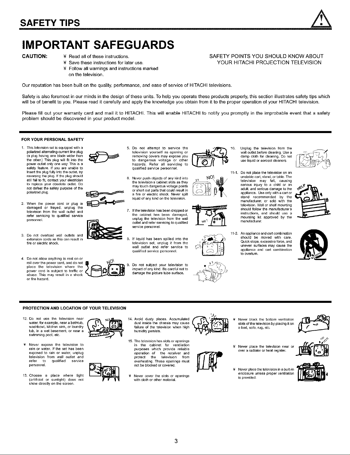
FOR YOUR PERSONAL SAFETY
1. This television set is equipped with a
peladzed absrnatJug-current line plug J_7--""_ _
(a plug having one blade wffier than
the o_er) This plug will fit into the
power oL_Jet only one way_ This is a
safety feature¸ If you are unable to
insert the plug fulty into the outlet, try
reversing the plug. If the plug should 6
still fail to fit, contact your electrician
to replace your obsolete ouget. DO
not defeat the safety purpose of Re
polarized plug¸ _
2_ When the power COrd or plug is _
damaged or frayed_ unpEug the
feievision from the wall outlet and 7_
refer servicing to quaE_ed service
personnel
3. DO not overload wail outlets and
extension cords as this can res=tlt in
fire or electric shock¸
4. DO not allow anything to rest on or
toil over the power cord, and do not _ _'_r_mr,_ 9
place the television where the
power cord is subject to traffic or
abuse_ This may result in a shock
or t_re hazard_
.,_,%
5 Do not attempt to service the
television yourself as opening or
removing covers may expose you
to dangerous voltage or other
hazards¸ Refer all servicing to
qualified service personnel¸
Never push objects of any kind into
tile television s cabinet sfets as they
may touch dangerous voltage points
or short out parts that could result in
a fire or electric shock¸ Never spill
liquid of any kind on the telewsion
If the t ffievision has been dropped or
the cabinet has been damaged,
unplug the television from the wail
outlet and refer servicing to qualified
service personnel
If liquid has been spilled into the
television set, =mplug it from the
wall outlet and refer service to
qualified service personnel.
Do not s_tbject yo_tr television to
impact of any kind Be careful not to
damage the picture tube surface.
10 Unplug the television from the
wail o_ttlet before cleaning Use a
damp cloth for cleaning. DO not
use liquid or aerosol cleaners¸
11-1. Do not place the felevision on an
unstable cart, stand, or table¸ The
television may fall, causing
serious injury to a child or an
adult, and serious damage to the
appliance. Use only with a cart or
stand recommended by the
manufacturer, or sold with the
television. Wall or shelf mounting
should follow the manufacturer s
instructions, and should use a
mounting kit approved by the
manufecture_
1%2. An appliance and cart combination
should be moved with care
Quick stops, excessive force, and
uneven surfaces may cause the
appliance and cart combination
to overturn¸
PROTECTION AND LOCATION OF YOUR TELEVISION
12 Do not use the television near
water, for example, near a bathtub,
washbowl, kitchen sink, or laundry
tub, in a wet basement, or near a
swimming pcol, etc.
¥ Never expose the television to
rain or water If the set has been
exposed to rain or water, unplug
television from wall outlet and
refer to qualffied service
personnel¸
13 Choose a place where light
(artificial or sunlight) does not
shine directly on the screen.
14 Avoid dusty places Accumulated f r_ ".1_11_-rl
dust inside the chassis may cause
failure of the television when high
humidity persists
t 5 The television has slOtS or openings
in the cabinet for ventilation
purposes which provide reliable
operation of the receiver and
protect the television from
overeating These openings must
not be blocked or covered¸
¥ Never cover the slots or openings
with cloth or other material
".€,
3
¥ Never block the bottom ventilation r_l,_t_]
slots of the television by placing it on
a bed, sofa, rug, etc
¥ Never place the tffievision near or /r_
over a radiator or heat register _
¥ Never place the television in a built-in
enclosure /_ffiess proper ventilation
is provided¸
PROTECTION AND LOCATION OF YOUR TELEVISION
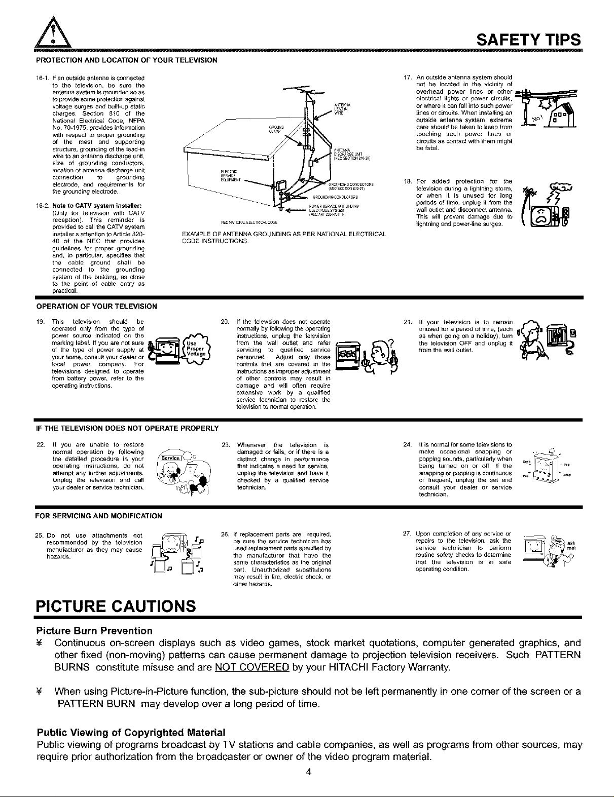
16-1. if an o=_tside antenna is connected
to the fetsvision, be s=_re the
antenna system is grounded so as
to provide some protection against
volfege surges and built-up stofts
charges¸ Section 810 of the
Nstional Etscfecal Code, NFPA
No 70_1975, provides information
with respect to proper grounding
of the mast and supporting
structure, grounding of the tsad-in
wire to an antenna discharge unit,
size of grounding conductors,
Iocafion of antenna discharge lJnit
connection to grounding
electrOde, end requirements for
the grounding electrode
16-2. Note to CATV system installer:
(Only for felevtston with CATV
reception)¸ This reminder is
provided to call the CATV system
installer s atfentton to Article 820_
40 of the NEC that provides
guidelines fet proper grounding
end, in particular, specifies that
the cebfe ground shstl be
connected to the grotJnding
system of the building, 8s close
to the point of cabts entry as
practical
EXAMPLE OF ANTENNA GROUNDING AS PER NATIONAL ELECTRICAL
CODE INSTRUCTIONS
OPERATION OF YOUR TELEVISION
19 This totsvtsrgn should be
operated only from the type of
power source indicated on the
marking tsbeL If you are not sure
of the type of Power suppEy a_
your home_ consuIl your dealer or
IocaE power company_ For
_etsvisions designed to ogerste
from battery power_ refer to the
eperating instructions_
GROUNDI_C0NDUCTORS
P0WERSERV_EGROL_NDI_
r_c _4A_IONA_ELECTr_ICALCODE
20. If the tetswstsn does not operate
normally by follow_ag the operating
instructtons, unplug the tetsvision
from the wtsl outJet and refer
servicing to qualified service
personnel Aftjust only those
controls that ate covered in the
instructions as improper adj*J stment
of other controls may resug in
damage and will often require
extensive work by a qualified
service technician to restore the
tetsvision to normal operation¸
(_EC_RT2_0PART_)
{NECSECT_0NB_02_]
SAFETY TIPS
17
An outside antenna system should
not be tscafed in the vicinity of
overhead power lines or other _h_mm_--"
etsctrtsal lights or power circuits,
or where it can fell into such power
tines or circuits¸ When ins fellin g an
outside antenna system, extreme
care should be taken to keep from
touching such power lines or
circuits as coofect with them might
be fetal.
18
For added protection for the
tetsvision dudng 8 lightning storm,
or when it is un_Jsed for long
periods of time, unplug it from the
wtsl oufiet and disconnect antenna¸
This wilt prevent damage due to
lightning end power-line surges¸
21. if yo_r tetsvtsion is to remain
unused for a period of time, (such
as when goiag on a holiday), tam _'_l _
the televtsion OFF and unplug it
from the wa,I o.,t,et _/_ _
IF THE TELEVISION DOES NOT OPERATE PROPERLY
22. If you are unable to restore
normal operation by ftstowing
the deteitsd procethJre in your
operating instructions, do not
attempt any f_sthel adiustmeofs
Unglag the tetsvtstsn and call
your dealer or service technician
23 Whenever the tetsvision is
damaged or fails, or if there is a
distinct change in performance
that indicates a need for service,
unplug the tetswsion and have it
checked by a qualified service
technician
24. It is normal for some televisions to
make occasional snapping or ._
being turned on or off if the
ooooagsound,oarfic.,a ,ywhen
snapping or popping is continuous
or frequent, unplug the set and
consult yo=_r dealer or service
technician
FOR SERVICING AND MODIFICATION
25 DO not use aftachmenfe not
recommended by the tetsvision
manufacturer as they may cause
hazards¸
26 if teptscement parts are required,
be s_re the service technician has
used replacement parts specified by
the man*Jfect*Jrer that have the
same charecfedsecs as the original
pert Unauthorized substitutions
may result in fire, electric shock, or
other hazards.
27. Upon comptsfion of any service or
repairs to the tetswsion, ask the
service technician to perform
roufine safety checks to determine
that the tetsvtsion is in safe
operating condition¸
PICTURE CAUTIONS
Picture Burn Prevention
¥ Continuous on-screen displays such as video games, stock market quotations, computer generated graphics, and
other fixed (non-moving) patterns can cause permanent damage to projection television receivers. Such PATTERN
BURNS constitute misuse and are NOT COVERED by your HITACHI Factory Warranty.
¥ When using Picture-in-Picture function, the sub-picture should not be left permanently in one corner of the screen or a
PATTERN BURN may develop over a long period of time.
Public Viewing of Copyrighted Material
Public viewing of programs broadcast by TV stations and cable companies, as well as programs from other sources, may
require prior authorization from the broadcaster or owner of the video program material.
4
ACCESSORIES
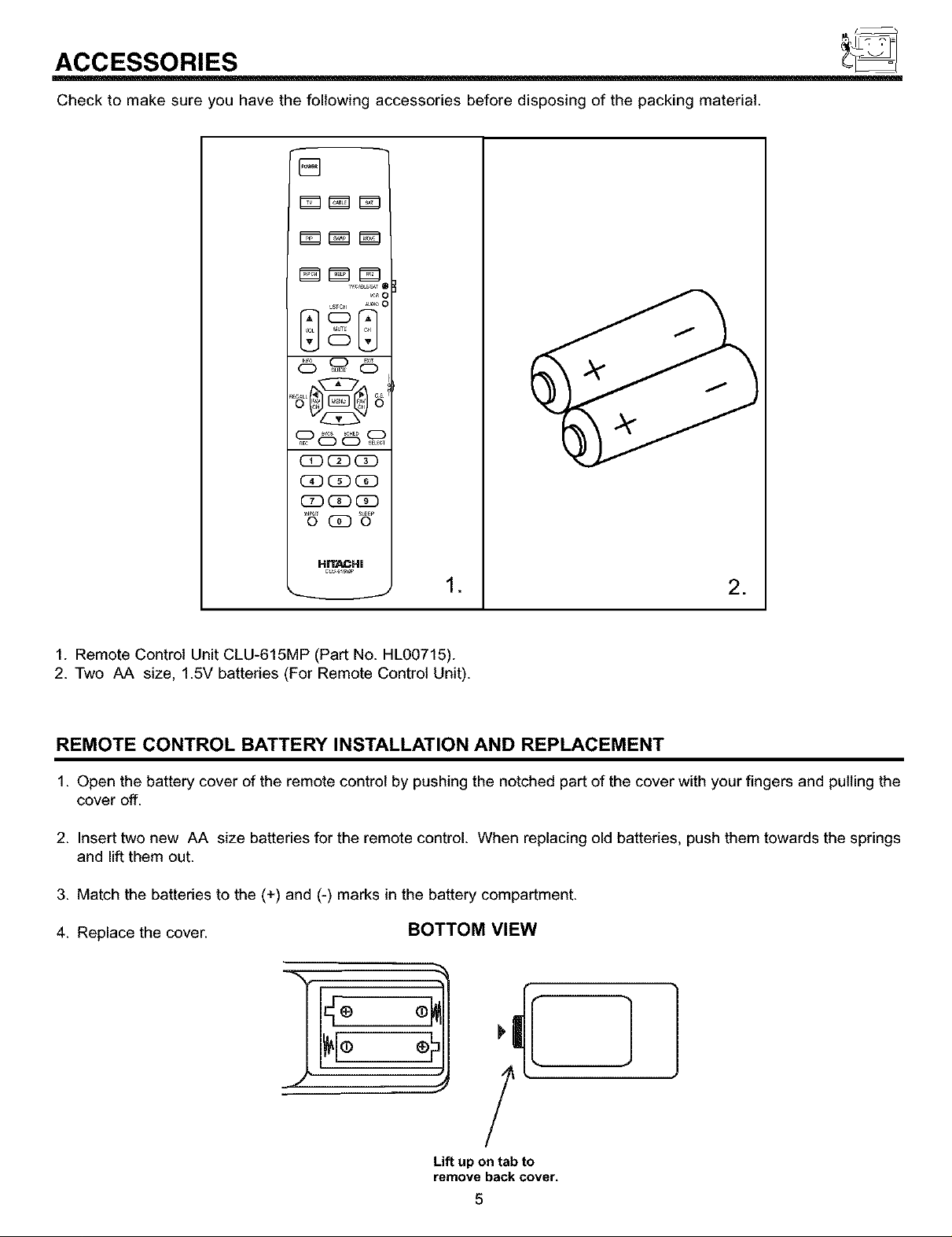
Check to make sure you have the following accessories before disposing of the packing material.
%
_Z_LTz_ i
CD CD CD
C_ (]D CE)
CC)(]D (!)
HITACHI
J
1. Remote Control Unit CLU-615MP (Part No. HL00715).
2. Two AA size, 1.5V batteries (For Remote Control Unit).
REMOTE CONTROL BATTERY INSTALLATION AND REPLACEMENT
1. Open the battery cover of the remote control by pushing the notched part of the cover with your fingers and pullingthe
cover off.
2. Insert two new AA size batteries for the remote control. When replacing old batteries, push them towards the springs
and lift them out.
3. Match the batteries to the (+) and (-) marks in the battery compartment.
4. Replace the cover. BOTTOM VIEW
.
*
.€
Lift up on tab to
remove back cover.
5
]
HOW TO SET UP YOUR NEW HITACHI PROJECTION TV
ANTENNA
Unless your TV is connected to a cable TV system or to a centralized antenna system, a good outdoor color TV antenna is
recommended for best performance. However, if you are located in an exceptionally good signal area that is free from interference and
multiple image ghosts, an indoor antenna may be sufficient.
LOCATION
Select an area where sunlight or bright indoor illumination will not fall directly on the picture screen. Also, be sure that the location
selected allows a free flow of air to and from the perforated back cover of the set.
To avoid cabinet warping, cabinet color changes, and increased chance of set failure, do not place the TV where temperatures can
become excessively hot, for example, in direct sunlight or near a heating appliance, etc.
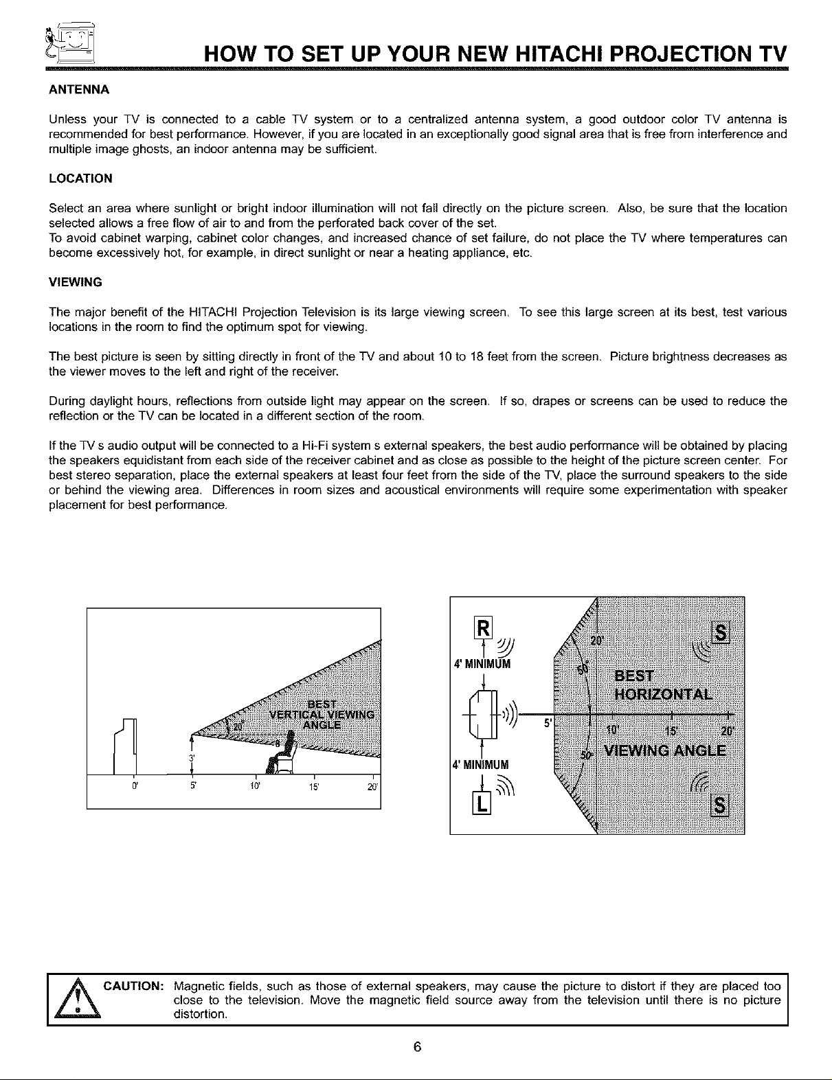
VIEWING
The major benefit of the HITACHI Projection Television is its large viewing screen. To see this large screen at its best, test various
locations in the room to find the optimum spot for viewing.
The best picture is seen by sitting directly in front of the TV and about 10 to 18 feet from the screen. Picture brightness decreases as
the viewer moves to the left and right of the receiver.
During daylight hours, reflections from outside light may appear on the screen. If so, drapes or screens can be used to reduce the
reflection or the TV can be located in a different section of the room.
Ifthe TV s audio output will be connected to a Hi-Fi system s external speakers, the best audio performance will be obtained by placing
the speakers equidistant from each side of the receiver cabinet and as close as possible to the height of the picture screen center. For
best stereo separation, place the external speakers at least four feet from the side of the TV, place the surround speakers to the side
or behind the viewing area. Differences in room sizes and acoustical environments will require some experimentation with speaker
placement for best performance.
4' MINIMUM
4' MINIMUM
CAUTION: Magnetic fields, such as those of external speakers, may cause the
,_ picture to distort if they are placed too I
distortion,closeto the television. Move the magnetic field source away from the television until there is no picture
6
I
HOOK-UP CABLES AND CONNECTORS
Most video/audio connections between components can be made with shielded video and audio cables that have phono connectors.
For best performance, video cables should use 75-Ohm coaxial shielded wire. Cables can be purchased from most stores that sell
audio/video products. Below are illustrations and names of common connectors. Before purchasing any cables, be sure of the output
and input connector types required by the various components and the length of each cable.
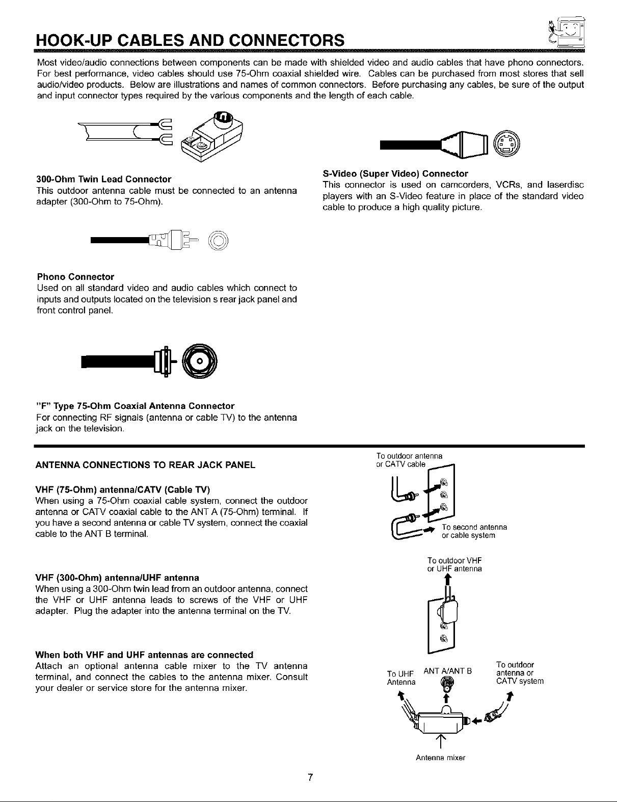
300-Ohm Twin Lead Connector
This outdoor antenna cable must be connected to an antenna
adapter (300-Ohm to 75-Ohm).
Phono Connector
Used on all standard video and audio cables which connect to
inputs and outputs located on the television s rear jack panel and
front control panel.
"F" Type 75-Ohm Coaxial Antenna Connector
For connecting RF signals (antenna or cable TV) to the antenna
jack on the television.
ANTENNA CONNECTIONS TO REAR JACK PANEL
S-Video (Super Video) Connector
This connector is used on camcorders, VCRs. and laserdisc
players with an S-Video feature in place of the standard video
cable to produce a high quality picture.
Tooutdoorantenna
VHF (75-Ohm) antennalCATV (Cable TV)
When using a 75-Ohm coaxial cable system, connect the outdoor
antenna or CATV coaxial cable to the ANT A (75-Ohm) terminal. If
you have a second antenna or cable TV system, connect the coaxial
cable to the ANT B terminal.
VHF (300-Ohm) antennalUHF antenna
When using a 300-Ohm twin lead from an outdoor antenna, connect
the VHF or UHF antenna leads to screws of the VHF or UHF
adapter, Plug the adapter into the antenna terminal on the TV,
When both VHF and UHF antennas are connected
Attach an optional antenna cable mixer to the TV antenna
terminal, and connect the cables to the antenna mixer. Consult
your dealer or service store for the antenna mixer.
_'_, Tosecondantenna
or cablesystem
To outdoor VHF
or UHF antenna
t
Tooutdoor
ToUHF ANT A!ANTB antennaor
Antenna _ CATVsystem
1"
Antenna mixer
7
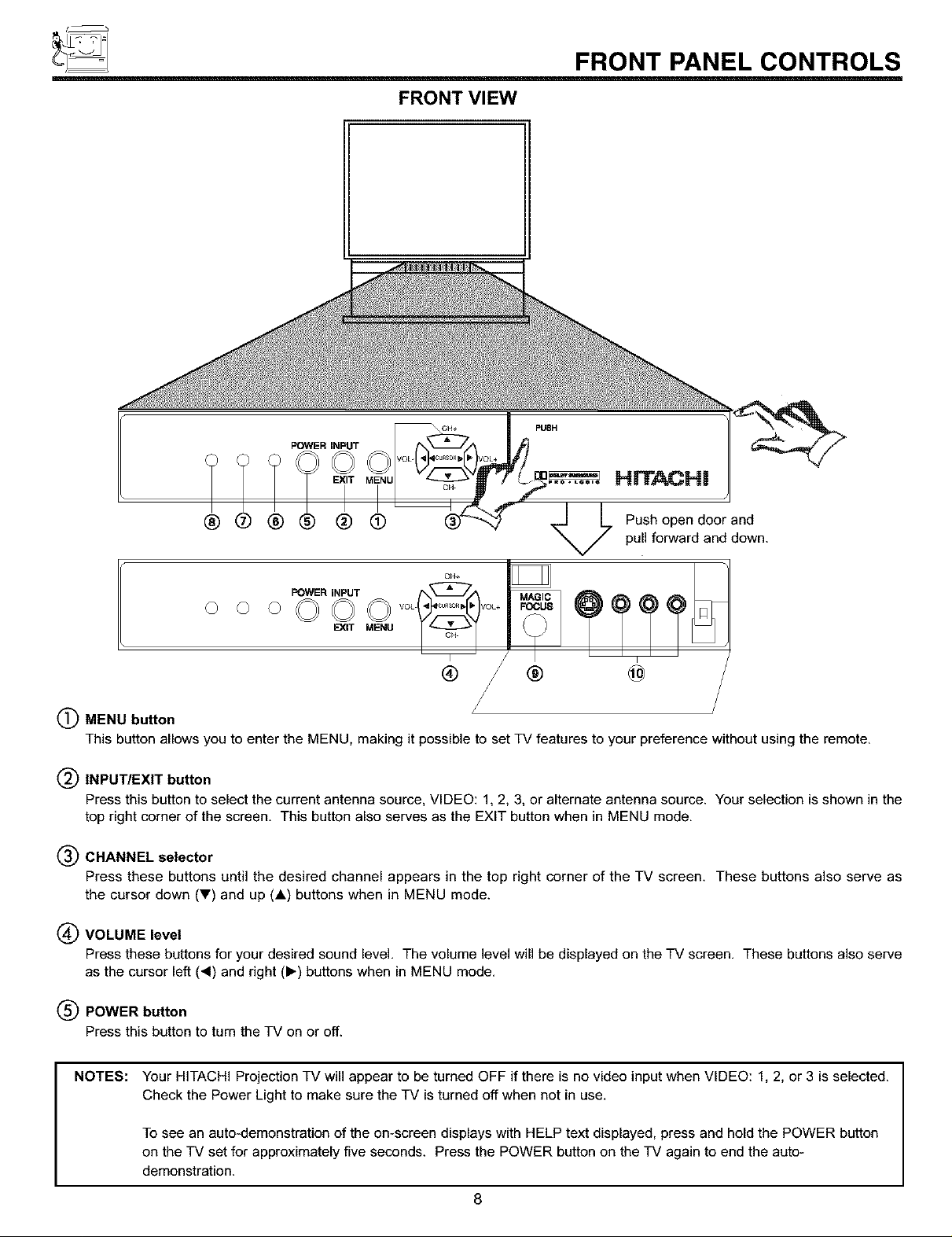
FRONT VIEW
CH+ pUSH
FRONT PANEL CONTROLS
®®®® j LPushopeodoorand
V pull forward and down.
FOWER iNPUT
000000
(_ MENU button z
This button allows you to enter the MENU, making it possible to set TV features to your preference without using the remote.
(_ INPUT/EXIT button
Press this button to select the current antenna source, VIDEO: 1, 2, 3, or alternate antenna source. Your selection is shown in the
top right corner of the screen. This button also serves as the EXIT button when in MENU mode.
(_) CHANNEL selector
Press these buttons until the desired channel appears in the top right corner of the TV screen. These buttons also serve as
the cursor down (_') and up (A) buttons when in MENU mode.
(_ VOLUME level
Press these buttons for your desired sound level. The volume level will be displayed on the TV screen. These buttons also serve
as the cursor left (4) and right (1_) buttons when in MENU mode.
EXIT MENU
® ® @
(_ POWER button
Press this button to turn the TV on or off.
NOTES:
Your HITACHI Projection TV will appear to be turned OFF if there is no video input when VIDEO: 1, 2, or 3 is selected.
Check the Power Light to make sure the TV is turned off when not in use.
To see an auto-demonstration of the on-screen displays with HELP text displayed, press and hold the POWER button
on the TV set for approximately five seconds. Press the POWER button on the TV again to end the auto-
demonstration.
8
FRONT PANEL CONTROLS
(_) POWER light
You will see a red light when the TV is turned on.
(_ AI (Artificial Intelligence) sensor
The Artificial Intelligence sensor will make automatic picture adjustments depending on the amount of light in the room to give the
best picture. (See page 54.)
(_) REMOTE CONTROL sensor
Point your remote at this area when selecting channels, adjusting volume, etc.
(_ MAGIC FOCUS
Use this button to adjust your picture quality to optimum performance. (See page 43.)
(_) FRONT INPUT JACKS (for VIDEO: 3)
Use these audio/video jacks for a quick hook-up from a camcorder or VCR to instantly view your favorite show or new recording,
Press the INPUT button untilVIDEO: 3 appears in the top right corner of the TV screen, If you have mono sound, insert the audio
cable into the left channel jack,
9
f_
_ FRONT PANEL JACKS AND CONNECTIONS
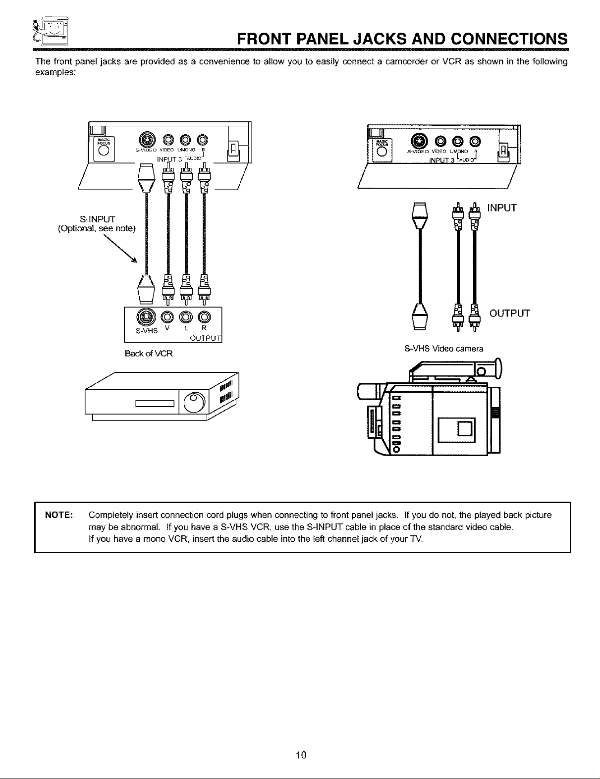
The front panel jacks are provided as a convenience to allow you to easily connect a camcorder or VCR as shown in the following
examples:
S.VIDEO VEDEO UMONO
INPUT_ LAu°_3
@ooo
S-INPUT
(Optional, see note)
\.
IllNPuT
OUTPUT
S-VHS V
Back of VCR
U
S-VHS Video camera
I
NOTE:
L
Completely insert connection cord plugs when connecting to front panel jacks. If you do not, the played back picture
may be abnormal If you have a S-VHS VCR, use the S-INPUT cable in place of the standard video cable.
If you have a mono VCR, insert the audio cable into the left channel jack of your TV.
10
REAR PANEL JACKS
f
O
ANTA
REAR SPEAKER
8Q ONLY
TO
CONVERTER
ANTB
< ONO < ONO ]
S-VIDEO SUB
@N
L k
@0,O
-Q
@R@R
AUDIO AUDIO
INPUT1 INPUT2 MONITOR
O
%,
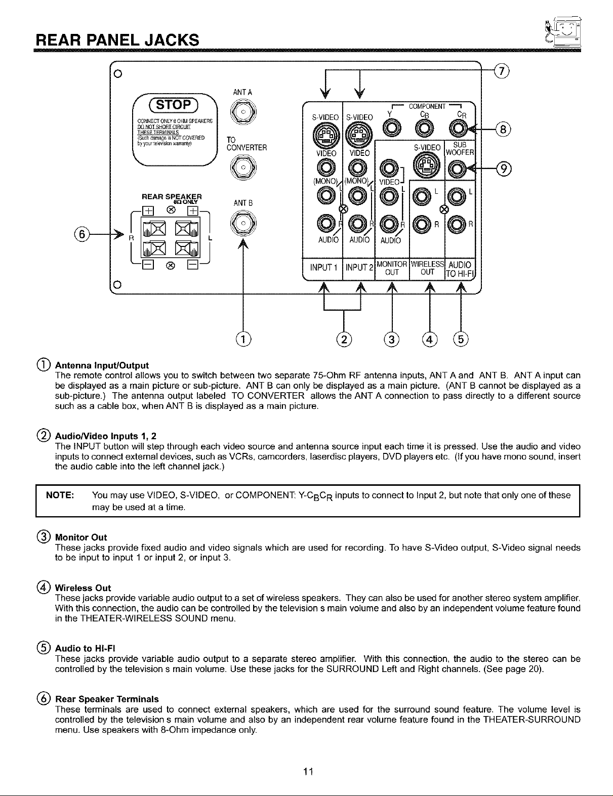
(_) Antenna Input/Output
The remote control allows you to switch between two separate 75-Ohm RF antenna inputs, ANT A and ANT B. ANT A input can
be displayed as a main picture or sub-picture. ANT B can only be displayed as a main picture. (ANT B cannot be displayed as a
sub-picture.) The antenna output labeled TO CONVERTER allows the ANT A connection to pass directly to a different source
such as a cable box, when ANT B is displayed as a main picture.
WIRELESSAUDIO
OUT
OUT TOHI-Fi
(_ AudioNideo Inputs 1, 2
The INPUT button will step through each video source and antenna source input each time it is pressed. Use the audio and video
inputs to connect external devices, such as VCRs, camcorders, laserdisc players, DVD players etc. (If you have mono sound, insert
the audio cable into the left channel jack.)
NOTE: You may use VIDEO, S-VIDEO, or COMPONENT: Y-CBC R inputs to connect to Input 2, but note that only one of these
may be used at a time.
(_) Monitor Out
These jacks provide fixed audio and video signals which are used for recording. To have S-Video output, S-Video signal needs
to be input to input 1 or input 2, or input 3.
(_ Wireless Out
These jacks provide variable audio output to a set of wireless speakers. They can also be used for another stereo system amplifier.
With this connection, the audio can be controlled by the television s main volume and also by an independent volume feature found
in the THEATER-WIRELESS SOUND menu.
(_ Audio to HI-FI
These jacks provide variable audio output to a separate stereo amplifier. With this connection, the audio to the stereo can be
controlled by the television s main volume. Use these jacks for the SURROUND Left and Right channels. (See page 20).
(_) Rear Speaker Terminals
These terminals are used to connect external speakers, which are used for the surround sound feature. The volume level is
controlled by the television s main volume and also by an independent rear volume feature found in the THEATER-SURROUND
menu. Use speakers with 8-Ohm impedance only.
11
(_) S-Video Inputs 1 and 2
Inputs 1 and 2 provide S-Video (Super Video) jacks for connecting equipment with S-Video output capability.
(_) Component: Y*CBC RInput 2
Input 2 provides Y-CBCR jacks for connecting equipment with this capability, such as a DVD player.
FIRST TIME USE
NOTES:
(_ Sub Woofer
This jack provides variable audio output to a sub-woofer accessory. With this connection, the audio can be controlled by the
television s main volume and also by an independent sub-woofer volume feature found in the THEATER-SUB WOOFER menu.
DO NOT connect standard VIDEO or S-VIDEO to Input 2 when using Y-CBC R input.
When using the Y-CBC R input jacks, connect your components audio output to the TV s Input 2 Left and Right Audio
input jacks.
Your component outputs may be labeled Y, B-Y, and R-Y. In this case, connect the components B-Y output to the TV s
Cb input and the components R-Y output to the TV s CR input.
It may be necessary to adjust TINT or turn AUTO COLOR-ON to obtain optimum picture quality when using the Y-CBC R
inputs. (See pages 53 and 54.)
To ensure no copyright infringement, the MONITOR OUT output will be abnormal, when using the Y-CBC R jacks.
When using the Y-CBC R jacks, Input 2 will be viewed as a blank PIP sub-picture. (See page 27.)
12
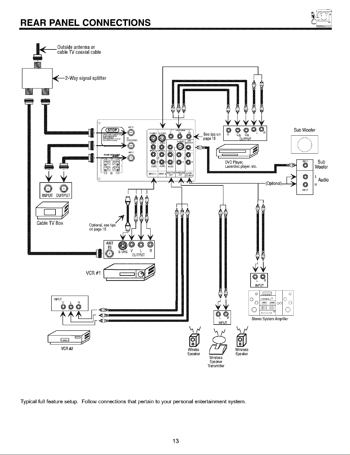
REAR PANEL CONNECTIONS
_ Outsideantennaor
cableTVcoaxialcable
2-Waysignalsplitter
INPUT 0 T
Cable TV Box
onpage15
jjjjjjjjjjjjjjjj_ V LOUTPUT
,f= =y @
VCR #2 Wirelss
_F
Speaker
Wirebss
Speaker
Transmitter
Stereo System Amplifier
Wirebss
Speaker
Typical full feature setup. Follow connections that pertain to your personal entertainment system,
13
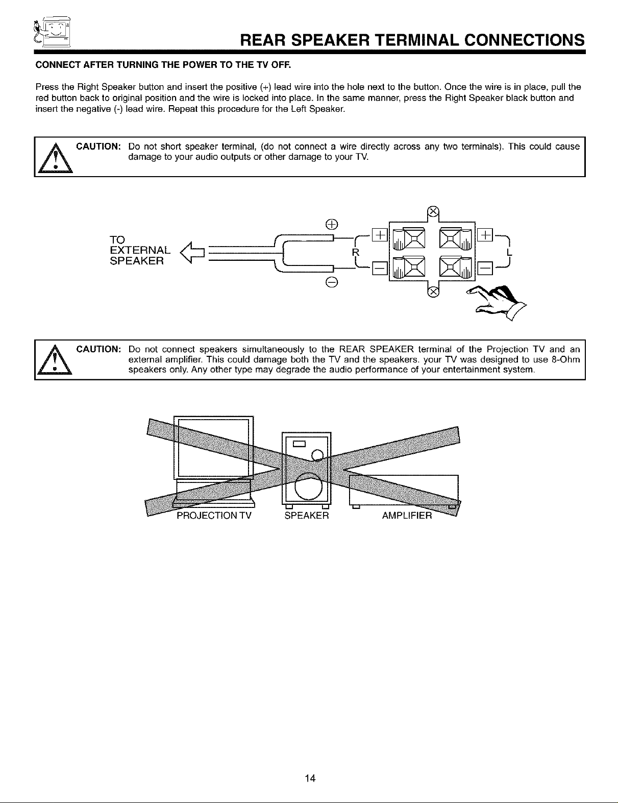
REAR SPEAKER TERMINAL CONNECTIONS
CONNECT AFTER TURNING THE POWER TO THE TV OFF.
Press the Right Speaker button and insert the positive (+) lead wire into the hole next to the button. Once the wire is in place, pull the
red button back to original position and the wire is locked into place. In the same manner, press the Right Speaker black button and
insert the negative (-) lead wire. Repeat this procedure for the Left Speaker.
I
,_ CAUTION: Do not short speaker terminal, (do not connect a wire directly across any two terminals). This could cause I
damage to your audio outputs or other damage to your TV.
A
TO
EXTERNAL
SPEAKER
_ CAUTION: Do not connect speakers simultaneously to the REAR SPEAKER terminal of the Projection TV and an
external amplifier. This could damage both the TV and the speakers, your TV was designed to use 8-Ohm
speakers only. Any other type may degrade the audio performance of your entertainment system.
I
PROJECTION TV SPEAKER AMPLIFIER
14
TIPS ON REAR PANEL CONNECTIONS
TIPS ON REAR PANEL CONNECTIONS
S-Video connections are provided for high performance laserdisc players, VCRs etc. that have this feature. Use these connections
in place of the standard video connection if your device has this feature.
If your device has only one audio output (mono sound), connect it to the left audio jack on the television.
Refer to the operating guide of your other electronic equipment for additional information on connecting your hook-up cables.
A single VCR can be used for VCR#1 and VCR#2, but note that a VCR cannot record its own video or line output. (INPUT:I in
example on page 11.) Refer to your VCR operating guide for more information on line input-output connection.
You may use VIDEO, S-VIDEO, or COMPONENT: Y-CBC R inputs to connect to Input 2, but note that only one of these may be
used at a time.
Connect only 1 component to each input jack.
COMPONENT: Y-CBC R connections are provided for high performance components, such as DVD players. Use these connections
in place of the standard video connection if your device has this feature.
When using the Y-CBC R input jacks, connect your components audio output to the TV s Input 2 Left and Right Audio input jacks.
Your component outputs may be labeled Y, B-Y, and R-Y. In this case, connect the components B-Y output to the TV s CB input
and the components R-Y output to the TV s CR input.
It may be necessary to adjust TINT or turn AUTO COLOR-ON to obtain optimum picture quality when using the Y-CBC R inputs.
(See pages 53 and 54.)
To ensure no copyright infringement, the MONITOR OUT output will be abnormal, when using the Y-CBC R jacks.
When using the Y-CBC R jacks, Input 2 will be viewed as a blank PIP sub-picture. (See page 27.)
15
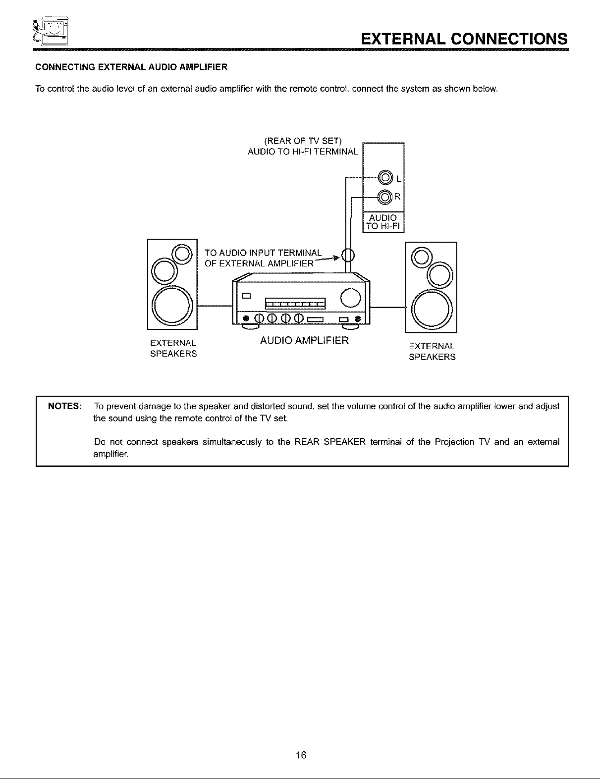
EXTERNAL CONNECTIONS
r
CONNECTING EXTERNAL AUDIO AMPLIFIER
To control the audio level of an external audio amplifier with the remote control, connect the system as shown below.
NOTES:
(REAR OF TV SET)
AUDIO TO HI-FI TERMINAL
m
--OL
--OR
i
AUDIO
TO HI-FI
TO AUDIO INPUT TERMINAL _ I
OF EXTERNAL AMPLIFIER ''''_ _
EXTERNAL
SPEAKERS
To prevent damage to the speaker and distorted sound, set the volume control of the audio amplifier lower and adjust
the sound using the remote control of the TV set.
AUDIO AMPLIFIER
/
EXTERNAL
SPEAKERS
Do not connect speakers simultaneously to the REAR SPEAKER terminal of the Projection TV and an external
amplifier,
16
CONNECTING EXTERNAL VIDEO SOURCES
The exact arrangement you use to connect the VCR, camcorder, laserdisc player, and DVD player to your TV set is dependent on the
model and features of each component. Check the owner s manual of each component for the location of video and audio inputs and
outputs.
The following connection diagrams are offered as suggestions. However, you may need to modify them to accommodate your particular
assortment of components and features. For best performance, video and audio cables should be made from coaxial shielded wire.
Before Operating External Video Source
The input mode is changed every time the INPUT button is pressed as shown below. Connect an external source to the INPUT terminal,
then press the INPUT button as necessary to view the input source. (See page 26.)
INPUT MODE SELECTION ORDER
(Antenna) (Input)
12 VIDEO
NOTE: When the TV is set to VIDEO and a video signal is not received from the VIDEO INPUT JACK on the jack panel of the
TV (i.e., VCR/laserdisc player, etc. is not connected or the video device is OFF), the set will appear to be OFF.
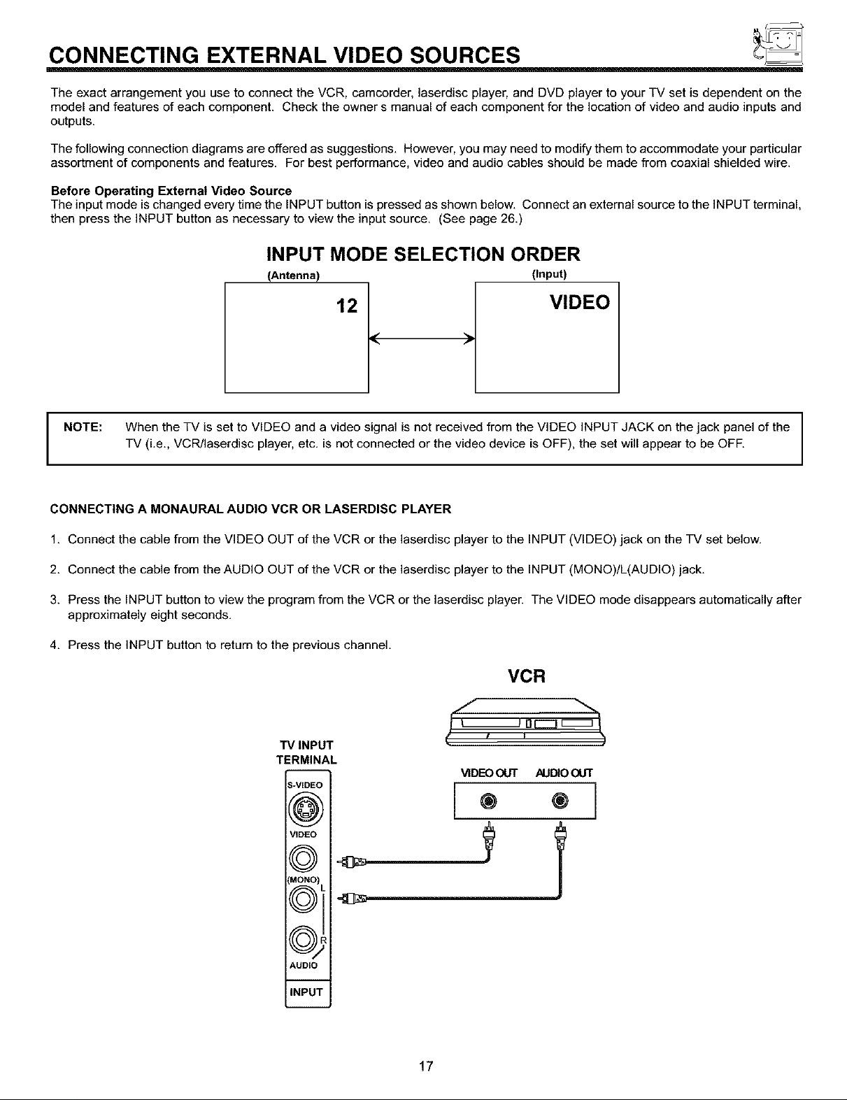
CONNECTING A MONAURAL AUDIO VCR OR LASERDISC PLAYER
1. Connect the cable from the VIDEO OUT of the VCR or the laserdisc player to the INPUT (VIDEO) jack on the TV set below.
2. Connect the cable from the AUDIO OUT of the VCR or the laserdisc player to the INPUT (MONO)/L(AUDIO) jack.
3. Press the INPUT button to view the program from the VCR or the laserdisc player. The VIDEO mode disappears automatically after
approximately eight seconds.
4. Press the INPUT button to return to the previous channel.
VCR
I , ,nEll|
TV INPUT
TERMINAL
-- VIDEOOUT AUI3_OOUT
S-VIDEO
K_J
IMONOI
VIDEO
ff_'_'N L
\'_vJl
AUDIO
INPUT
17
CONNECTING EXTERNAL VIDEO SOURCES
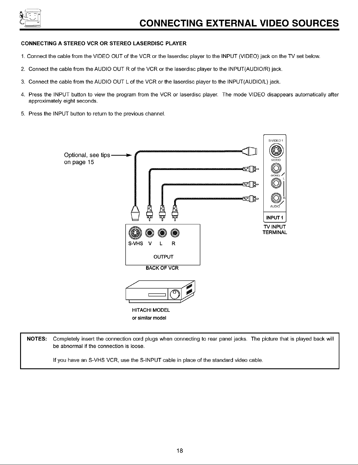
CONNECTING A STEREO VCR OR STEREO LASERDISC PLAYER
1. Connect the cable from the VIDEO OUT of the VCR or the laserdisc player to the INPUT (VIDEO) jack on the TV set below.
2. Connect the cable from the AUDIO OUT R of the VCR or the laserdisc player to the INPUT(AUDIO/R) jack.
3. Connect the cable from the AUDIO OUT L of the VCR or the laserdisc player to the INPUT(AUDIO/L) jack.
4. Press the INPUT button to view the program from the VCR or laserdisc player. The mode VIDEO disappears automatically after
approximately eight seconds.
5. Press the INPUT button to return to the previous channel.
S-VIDEO 1
Optional. see tips._- f_
on page 15
S-VHS V L R
HITACHI MODEL
or similar model
(@)
VIDEO
©i
©)
INPUT1
TV INPUT
TERMINAL
OUTPUT
BACK OF VCR
NOTES: Completely insert the connection cord plugs when connecting to rear panel jacks. The picture that is played back will
be abnormal if the connection is loose.
If you have an S-VHS VCR, use the S-INPUT cable in place of the standard video cable.
18
CONNECTING EXTERNAL VIDEO SOURCES
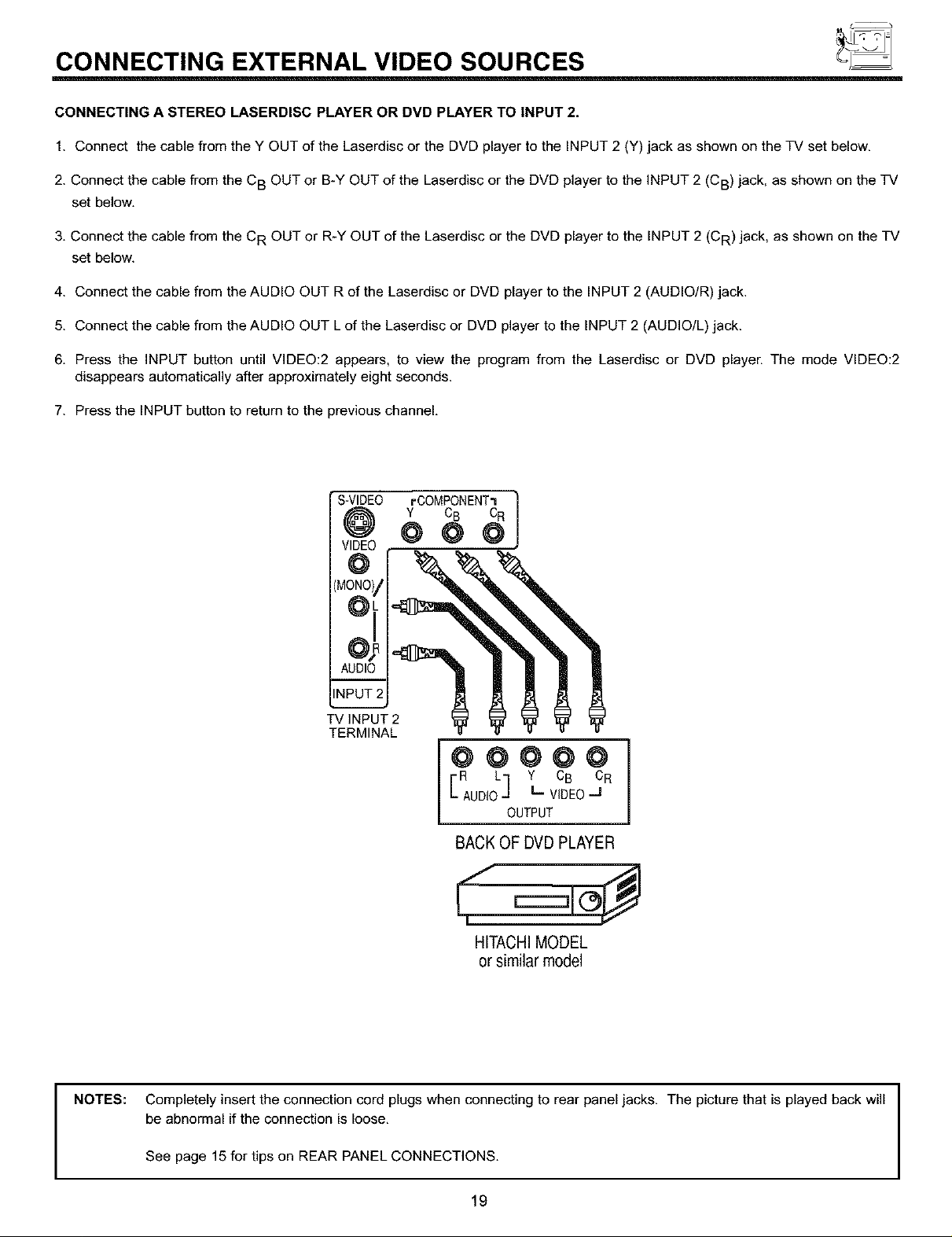
CONNECTING A STEREO LASERDISC PLAYER OR DVD PLAYER TO INPUT 2.
1. Connect the cable from the Y OUT of the Laserdisc or the DVD player to the INPUT 2 (Y) jack as shown on the TV set below,
2. Connect the cable from the CB OUT or B-Y OUT of the Laserdisc or the DVD player to the INPUT 2 (CB) jack, as shown on the TV
set below.
3. Connect the cable from the CR OUT or R-Y OUT of the Laserdisc or the DVD player to the INPUT 2 (CR) jack, as shown on the TV
set below.
4. Connect the cable from the AUDIO OUT R of the Laserdisc or DVD player to the INPUT 2 (AUDIO/R) jack.
5. Connect the cable from the AUDIO OUT L of the Laserdisc or DVD player to the INPUT 2 (AUDIO/L) jack.
6. Press the INPUT button until VIDEO:2 appears, to view the program from the Laserdisc or DVD player. The mode VIDEO:2
disappears automatically after approximately eight seconds.
7. Press the INPUT button to return to the previous channel.
' S-VIDEO =-COMPONENT'=|
Y CB CR
V,DE0@ @ @
@
R L Y CB CR
E AUDIOJ L. VIDEOJ
@@@@@
BACKOFDVDPLAYER
HITACHIMODEL
orsimilarm0del
J
OUTPUT
NOTES:
Completely insert the connection cord plugs when connecting to rear panel jacks. The picture that is played back will
be abnormal if the connection is loose.
See page 15 for tips on REAR PANEL CONNECTIONS.
19
_ AUDIO SYSTEM SETUP
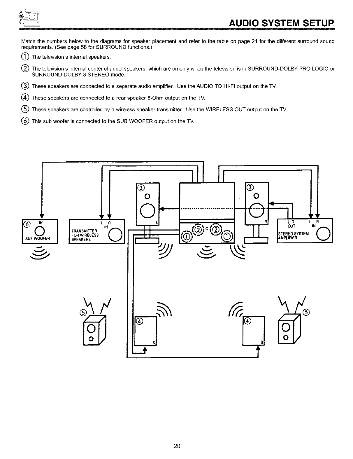
Match the numbers below to the diagrams for speaker placement and refer to the table on page 21 for the different surround sound
requirements. (See page 58 for SURROUND functions.)
(_The television s internal speakers.
The television s internal center channel speakers, which are on only when the television is in SURROUND-DOLBY PRO LOGIC or
SURROUND-DOLBY 3 STEREO mode.
(_) These speakers are connected to a separate audio amplifier. Use the AUDIO TO HI-FI output on the TV.
(_ These speakers are connected to a rear speaker 8-Ohm output on the TV.
(_ These speakers are controlled by a wireless speaker transmitter. Use the WIRELESS OUT output on the TV.
(_) This sub woofer is connected to the SUB WOOFER output on the TV.
Ill Ii
' ¶r ' r
"°°"'°''"*°'°*°°'°'°'°'"
f _%__" %_w_# ,r,c STEM
,0, ,©' _N
"-'®"®'-"P-<Iioo, ,Ol
D
$
J
2O
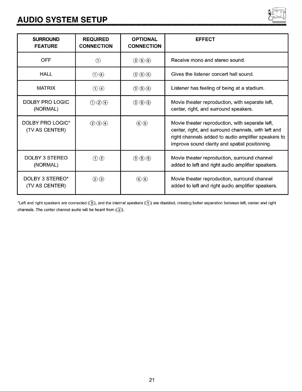
AUDIO SYSTEM SETUP
SURROUND REQUIRED OPTIONAL EFFECT
FEATURE CONNECTION CONNECTION
OFF L3_ _3_L_ _ Receive mono and stereo sound.
HALL L3_ _ _3_L__ Gives the listener concert hall sound.
MATRIX _ _ _3_L__ Listener has feeling of being at a stadium.
DOLBY PRO LOGIC _ _ _ _3_L-__ Movie theater reproduction, with separate left,
(NORMAL) center, right, and surround speakers.
DOLBY PRO LOGIC* _ _ _ _ _6_ Movie theater reproduction, with separate left,
(TV AS CENTER) center, right, and surround channels, with left and
right channels added to audio amplifier speakers to
improve sound clarity and spatial positioning.
DOLBY 3 STEREO _ @_ _3_L_ _ Movie theater reproduction, surround channel
(NORMAL) added to left and right audio amplifier speakers.
DOLBY 3 STEREO* _ _ _ _6_ Movie theater reproduction, surround channel
(TV AS CENTER) added to left and right audio amplifier speakers.
*Left and right speakers are connected (_3_), and the internal speakers (_) are disabled, creating better separation between left, center and right
channels. The center channel audio will be heard from (_).
21
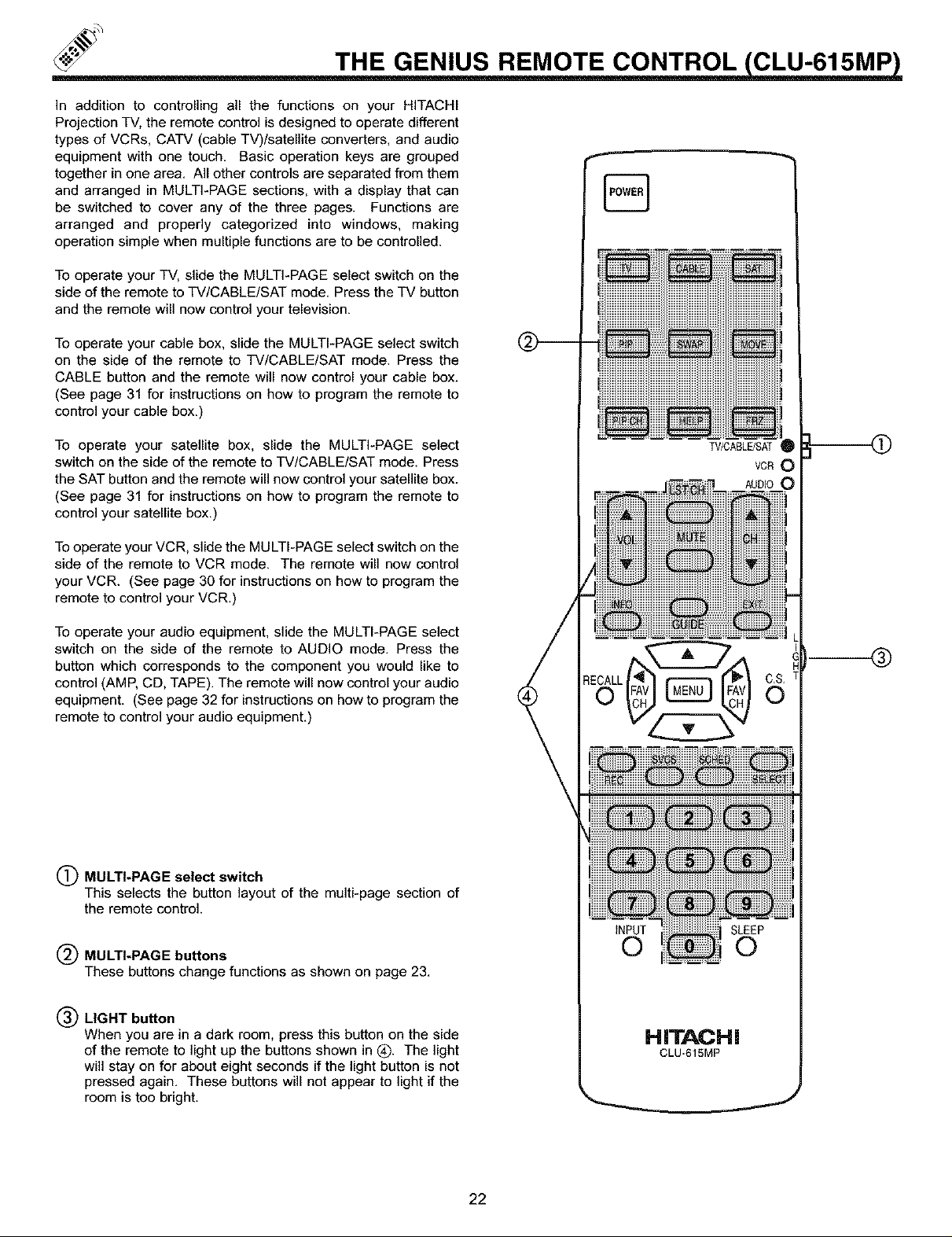
THE GENIUS REMOTE CONTROL CLU-615MP
In addition to controlling all the functions on your HITACHI
Projection TV, the remote control is designed to operate different
types of VCRs, CATV (cable TV)/satellite converters, and audio
equipment with one touch. Basic operation keys are grouped
together in one area. All other controls are separated from them
and arranged in MULTI-PAGE sections, with a display that can
be switched to cover any of the three pages. Functions are
arranged and properly categorized into windows, making
operation simple when multiple functions are to be controlled.
To operate your TV, slide the MULTI-PAGE select switch on the
side of the remote to TV/CABLE/SAT mode. Press the TV button
and the remote will now control your television.
To operate your cable box, slide the MULTI-PAGE select switch
on the side of the remote to TV/CABLE/SAT mode. Press the
CABLE button and the remote will now control your cable box.
(See page 31 for instructions on how to program the remote to
control your cable box.)
To operate your satellite box, slide the MULTI-PAGE select
switch on the side of the remote to TV/CABLE/SAT mode. Press
the SAT button and the remote will now control your satellite box.
(See page 31 for instructions on how to program the remote to
control your satellite box.)
To operate your VCR, slide the MULTI-PAGE select switch on the
side of the remote to VCR mode. The remote will now control
your VCR. (See page 30 for instructions on how to program the
remote to control your VCR.)
To operate your audio equipment, slide the MULTI-PAGE select
switch on the side of the remote to AUDIO mode. Press the
button which corresponds to the component you would like to
control (AMP, CD, TAPE). The remote will now control your audio
equipment. (See page 32 for instructions on how to program the
remote to control your audio equipment.)
(_) MULTI-PAGE select switch
This selects the button layout of the multi-page section of
the remote control.
MULTI-PAGE buttons
These buttons change functions as shown on page 23.
®
INPUT SLEEP
0 0
(_ LIGHT button
When you are in a dark room, press this button on the side
of the remote to light up the buttons shown in (_. The light
will stay on for about eight seconds if the light button is not
pressed again. These buttons will not appear to light if the
room is too bright.
HITACHi
CLU-61SMP
22
 Loading...