


PROJECTION COLOR TV
Operating Guide for 57F510, 51F510
IMPORTANT SAFETY INSTRUCTIONS................................................................................ 2-3
FIRST TIME USE .................................................................................................................. 4-18
THE REMOTE CONTROL .................................................................................................. 19-32
ON-SCREEN DISPLAY........................................................................................................ 33-65
CARE OF YOUR HITACHI TELEVISION ..................................................................................66
RECEPTION PROBLEMS..........................................................................................................67
USEFUL INFORMATION / INDEX ...................................................................................... 68-72
As an ENERGY STAR®Partner, Hitachi, Ltd. has determined that this
product meets the ENERGY STAR®guidelines for energy efficiency.
IMPORTANT SAFETY INSTRUCTIONS
2
SAFETY POINTS YOU SHOULD KNOW ABOUT
YOUR HITACHI TELEVISION
Our reputation has been built on the quality, performance, and ease of service of HITACHI televisions.
Safety is also foremost in our minds in the design of these units. To help you operate these products properly, this
section illustrates safety tips which will be of benefit to you. Please read it carefully and apply the knowledge you
obtain from it to the proper operation of your HITACHI television.
Please fill out your warranty card and mail it to HIT ACHI. This will enable HITACHI to notify you promptly in the improbable event that a safety problem should be discovered in your product model.
Follow all warnings and instructions marked on this television.
CAUTION
RISK OF ELECTRIC SHOCK
DO NOT OPEN
CAUTION: TO REDUCE THE RISK OF ELECTRIC SHOCK,
DO NOT REMOVE COVER (OR BACK).
NO USER SERVICEABLE PARTS INSIDE.
REFER SERVICING TO QUALIFIED SERVICE PERSONNEL.
The lightning flash with arrowhead symbol, within an equilateral triangle, is intended to alert the user to the presence of uninsulated
“dangerous voltage” within the product’s enclosure that may be of a
sufficient magnitude to constitute a risk of electric shock to persons.
The exclamation point within an equilateral triangle, is intended to
alert the user to the presence of important operating and maintenance (servicing) instructions in the literature accompanying the
appliance.
WARNING: • TO REDUCE THE RISK OF FIRE OR ELECTRIC SHOCK, DO NOT EXPOSE THIS APPARATUS
TO RAIN OR MOISTURE.
• THE TELEVISION SHOULD NOT BE EXPOSED TO DRIPPING OR SPLASHING AND OBJECTS
FILLED WITH LIQUIDS, SUCH AS VASES, SHOULD NOT BE PLACED ON THE TELEVISION.
NOTE: • There are no user serviceable parts inside the television.
• Model and serial numbers are indicated on back side of the television.
POWER SOURCE
THIS
TELEVISION
IS DESIGNED TO OPERATE ON 120 VOLTS 60Hz, AC CURRENT. INSERT THE
POWER CORD INTO A 120 VOLT 60Hz OUTLET.
TO PREVENT ELECTRIC SHOCK, DO NOT USE THE TELEVISION’S (POLARIZED) PLUG WITH AN
EXTENSION CORD, RECEPTACLE, OR OTHER OUTLET UNLESS THE BLADES AND GROUND TERMINAL CAN BE FULLY INSERTED TO PREVENT BLADE EXPOSURE.
NEVER CONNECT THE
TELEVISION
TO 50Hz, DIRECT CURRENT, OR ANYTHING OTHER THAN THE
SPECIFIED VOLTAGE.
CAUTION: Never remove the back cover of the television as this can expose you to very high voltages and other haz-
ards. If the television does not operate properly, unplug the television and call your authorized dealer or
service center.
NOTE: This television receiver will display television closed captioning, ( or ), in accordance with
paragraph 15.119 and 15.122 of the FCC rules.
CAUTION:
Adjust only those controls that are covered in the instructions, as improper changes or modifications not expressly approved by HITACHI could void the user’s authority to operate the television.
MODIFICATIONS:
The FCC requires the user to be notified that any changes or modifications made to this device that
are not expressly approved by Hitachi America, Ltd. Home Electronics Division may void the user’s
authority to operate the equipment.
ANTENNA
LEAD IN
WIRE
ANTENNA
DISCHARGE UNIT
(NEC SECTION 810-20)
GROUNDING CONDUCTORS
(NEC SECTION 810-21)
GROUNDING CONDUCTORS
POWER SERVICE GROUNDING
ELECTRODE SYSTEM
(NEC ART 250 PART H)
NEC NATIONAL ELECTRICAL CODE
ELECTRIC
SERVICE
EQUIPMENT
GROUND
CLAMP
IMPORTANT SAFETY INSTRUCTIONS
3
Read before operating equipment
Follow all warnings and instructions marked on this television.
1. Read these instructions.
2. Keep these instructions.
3. Heed all warnings.
4. Follow all instructions.
5. Do not use this apparatus near water.
6. Clean only with a dry cloth.
7. Do not block any ventilation openings. Install in accordance
with the manufacturer’s instructions.
8. Do not install near any heat sources such as radiators, heat
registers, stoves, or other apparatus (including amplifiers)
that produce heat.
9. Do not defeat the safety purpose of the polarized or grounding-type plug. A polarized plug has two blades with one
wider than the other. A grounding type plug has two blades
and a third grounding prong. The wide blade or the third
prong are provided for your safety. If the provided plug does
not fit into your outlet, consult an electrician for replacement
of the obsolete outlet.
10. Protect the power cord from being walked on or pinched particularly at plugs, convenience receptacles, and the point
where they exit from the apparatus.
11. Only use the attachments/accessories specified by the manufacturer.
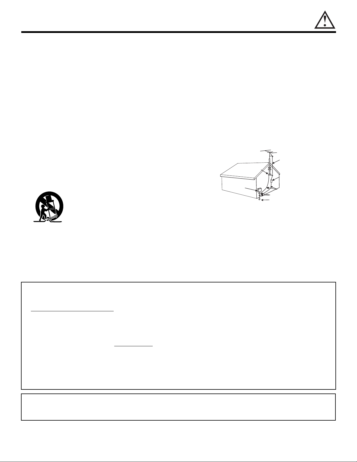
12. Use only with the cart, stand, tripod, bracket, or table specified by the manufacturer,
or sold with the apparatus. When a cart is
used, use caution when moving the
cart/apparatus combination to avoid injury
from tip-over.
13. Unplug this apparatus during lightning storms or when
unused for long periods of time.
14. Refer all servicing to qualified service personnel. Servicing
is required when the apparatus has been damaged in any
way, such as power-supply cord or plug is damaged, liquid
has been spilled or objects have fallen into apparatus, the
apparatus has been exposed to rain or moisture, does not
operate normally, or has been dropped.
15. Televisions are designed to comply with the recommended
safety standards for tilt and stability.
Do not apply excessive pulling force to the front, or top, of the
cabinet which could cause the product to overturn resulting
in product damage and/or personal injury.
16. Follow instructions for wall, shelf or ceiling mounting as recommended by the manufacturer.
17. An outdoor antenna should not be located in the vicinity of
overhead power lines or other electrical circuits.
18. If an outside antenna is connected to the receiver be sure the
antenna system is grounded so as to provide some protection against voltage surges and built up static charges.
Section 810 of the National Electric Code, ANSI/NFPA No.
70-1984, provides information with respect to proper grounding for the mast and supporting structure, grounding of the
lead-in wire to an antenna discharge unit, size of grounding
connectors, location of antenna-discharge unit, connection to
grounding electrodes and requirements for the grounding
electrode.
Note to the CATV system installer: This reminder is provided to call the CATV system installer’s attention to Article 82040 of the NEC that provides guidelines for proper grounding
and, in particular, specifies that the cable ground shall be
connected to the grounding system of the building, as close
to the point of cable entry as practical.
• Do not place any objects on the top of the television which may fall or cause a child to climb to retrieve the objects.
• Projection TV’s are heavy and can mark or damage floor surfaces (especially wood flooring) if moved improperly. Do not slide or
force TV into position. Always roll TV allowing casters at bottom of unit to help steer and position the TV.
• PREVENTION
OF SCREEN BURN
This Wide Screen TV is designed to display wide screen pictures. Images should be viewed mostly in wide screen format or
zoomed to fit the screen with moving pictures. Use of side panels, top and bottom panels of standard picture formats should only
be 15% of your total viewing time to prevent uneven aging of the phosphors. Phosphors in the lighted area of the picture will age
more rapidly than the gray areas. Continuous on-screen displays such as video games, stock market quotations, computer
generated graphics, and other fixed (non-moving) patterns can cause permanent damage to television receivers. Such “SCREEN
BURNS” constitute misuse and are NOT
COVERED by your HITACHI Factory Warranty.
• PUBLIC VIEWING OF COPYRIGHTED MATERIAL
Public viewing of programs broadcast by TV stations and cable companies, as well as programs from other sources, may require
prior authorization from the broadcaster or owner of the video program material.
• This product incorporates copyright protection technology that is protected by U.S. patents and other intellectual property rights.
Use of this copyright protection technology must be authorized by Macrovision Corporation, and is intended for home and other
limited consumer uses only unless otherwise authorized by Macrovision. Reverse engineering or disassembly is prohibited.
This product contains lead. Dispose of this product in accordance with applicable environmental laws. For product recycling and disposal information, contact your local government agency or the Electronic Industries Alliance
at www.eiae.org (in the US) or the Electronic Product Stewardship Canada at www.epsc.ca (in Canada). For more
information, call 1-800-HITACHI.
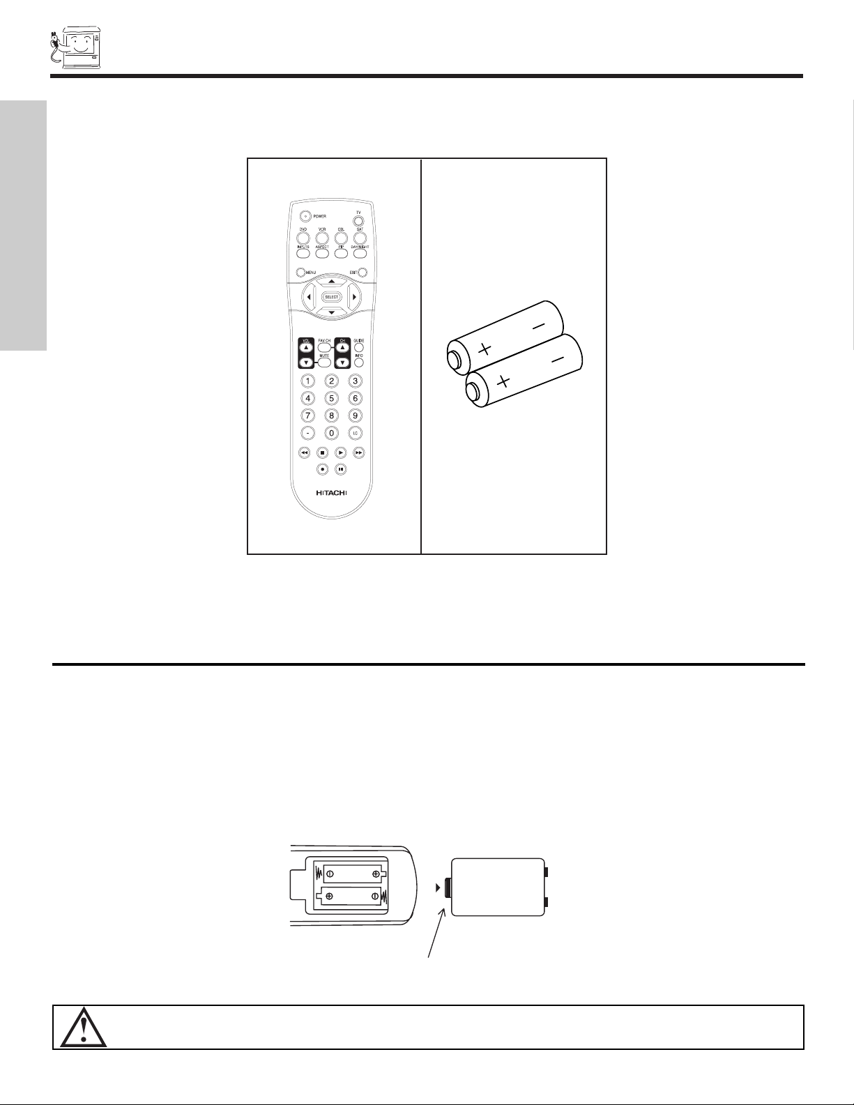
ACCESSORIES
4
1. Remote Control Unit CLU-4341UG2 (Part No. HL02071).
2. Two “AA” size, 1.5V batteries (For Remote Control Unit).
REMOTE CONTROL BATTERY INSTALLATION AND REPLACEMENT
1. Open the battery cover of the remote control by pushing down and sliding the back cover off.
2. Insert two new “AA” size batteries for the remote control. When replacing old batteries, push them towards the springs
and lift them out.
3. Match the batteries to the (+) and (-) marks in the battery compartment.
4. Replace the cover.
BOTTOM VIEW
Lift up on tab to
remove back cover.
(Remote Control)
CAUTION: Danger of explosion if battery is incorrectly replaced. Replace with the same or equivalent type.
Check to make sure you have the following accessories before disposing of the packing material.
1.
2.
REMOTE CONTROL
BATTERIES
(“AA”)
FIRST TIME USE
HOW TO SET UP YOUR NEW HITACHI PROJECTION TV
5
CAUTION: Magnetic fields, such as those of external speakers, may cause the picture to distort if they are placed too
close to the television. Move the magnetic field source away from the television until there is no picture
distortion.
ANTENNA
Unless your TV is connected to a cable TV system or to a centralized antenna system, a good outdoor TV antenna is recommended for
best performance. However, if you are located in an exceptionally good signal area that is free from interference and multiple image
ghosts, an indoor antenna may be sufficient.
LOCATION
Select an area where sunlight or bright indoor illumination will not fall directly on the picture screen. Also, be sure that the location
selected allows a free flow of air to and from the perforated back cover of the set.
To avoid cabinet warping, cabinet color changes, and increased chance of set failure, do not place the TV where temperatures can
become excessively hot, for example, in direct sunlight or near a heating appliance, etc.
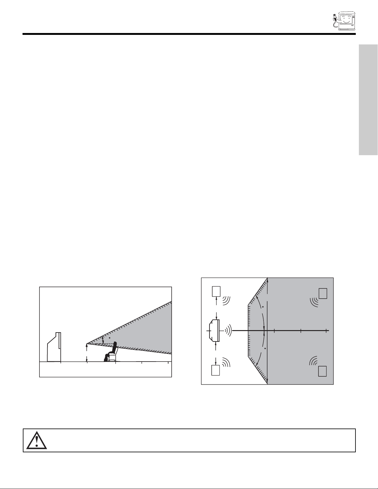
VIEWING
The major benefit of the HITACHI Projection Television is its large viewing screen. To see this large screen at its best, test various
locations in the room to find the optimum spot for viewing.
The best picture is seen by sitting directly in front of the TV and about 10 to 18 feet from the screen. Picture brightness decreases as
the viewer moves to the left and right of the receiver.
During daylight hours, reflections from outside light may appear on the screen. If so, drapes or screens can be used to reduce the
reflection or the TV can be located in a different section of the room.
If the TV’s audio output will be connected to a Hi-Fi system’s external speakers, the best audio performance will be obtained by placing
the speakers equidistant from each side of the receiver cabinet and as close as possible to the height of the picture screen center. For
best stereo separation, place the external speakers at least four feet from the side of the TV, place the surround speakers to the side
or behind the viewing area. Differences in room sizes and acoustical environments will require some experimentation with speaker
placement for best performance.
FIRST TIME USE
R
4" Minimum
BEST
VERTICAL VIEWING
20
3’
0’
5’
10’
ANGLE
15’
20’
4" Minimum
L
50
BEST
HORIZONTAL
5’
10’
VIEWING ANGLE
50
15’
S
20’
S
HOOK-UP CABLES AND CONNECTORS
6
ANTENNA CONNECTIONS TO REAR JACK PANEL
VHF (75-Ohm) antenna/CATV (Cable TV)
When using a 75-Ohm coaxial cable system, connect CATV coaxial cable to the ANT
A (75-Ohm) terminal. If you have an antenna, connect the coaxial cable to the ANT
B terminal.
VHF (300-Ohm) antenna/UHF antenna
When using a 300-Ohm twin lead from an outdoor antenna, connect the VHF or
UHF antenna leads to screws of the VHF or UHF adapter. Plug the adapter into
the antenna terminal on the TV.
When both VHF and UHF antennas are connected
Attach an optional antenna cable mixer to the TV antenna terminal, and connect
the cables to the antenna mixer. Consult your dealer or service store for the
antenna mixer.
r
Most video/audio connections between components can be made with shielded video and audio cables that have phono connectors.
For best performance, video cables should use 75-Ohm coaxial shielded wire. Cables can be purchased from most stores that sell
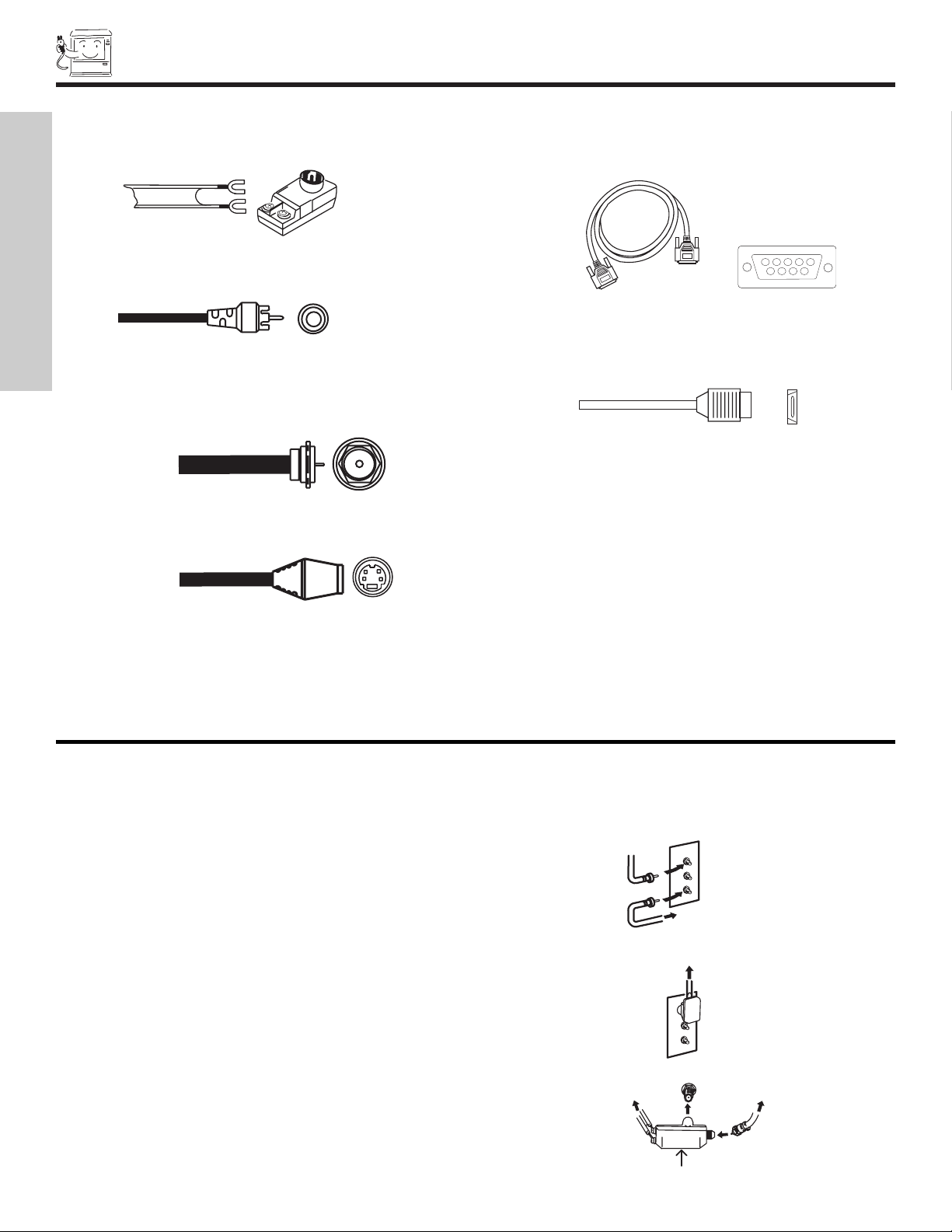
audio/video products. Below are illustrations and names of common connectors. Before purchasing any cables, be sure of the output
and input connector types required by the various components and the length of each cable.
300-Ohm Twin Lead Connector
This outdoor antenna cable must be connected to an antenna
adapter (300-Ohm to 75-Ohm).
Phono Connector
Used on all standard video and audio cables which connect to
inputs and outputs located on the television’s rear jack panel
and front control panel.
“F” Type 75-Ohm Coaxial Antenna Connector
For connecting RF signals (antenna or cable TV) to the antenna
jack on the television.
S-Video (Super Video) Connector
This connector is used on camcorders, VCRs and laser- disc
players with an S-Video feature in place of the
standard video cable to produce a high quality picture.
D-SUB MINI 9-Pin Cable
This cable is used to connect to the RS232C input located on the
rear panel so you can control some of your TV functions from an
external home control system.
HDMI Cable
This cable is used to connect your external devices such as SetTop-Boxes or DVD players equipped with an HDMI output connection to the TV’s HDMI input.
FIRST TIME USE
54321
9876
To outdoor antenna
or CATV cable
To second antenna
or cable system
To outdoor VHF
or UHF antenna
From UHF antenna
ANT A/ANT B
Antenna Mixer
From outdoo
antenna or
CATV System
FRONT PANEL CONTROLS
7
INPUT 5
S-VIDEO
VIDEO
AUDIO
L/MONO
R
EXIT
INPUT
SELECT
MENU
VOL- VOL+ CH- CH+
CURSOR
MAGIC
FOCUS
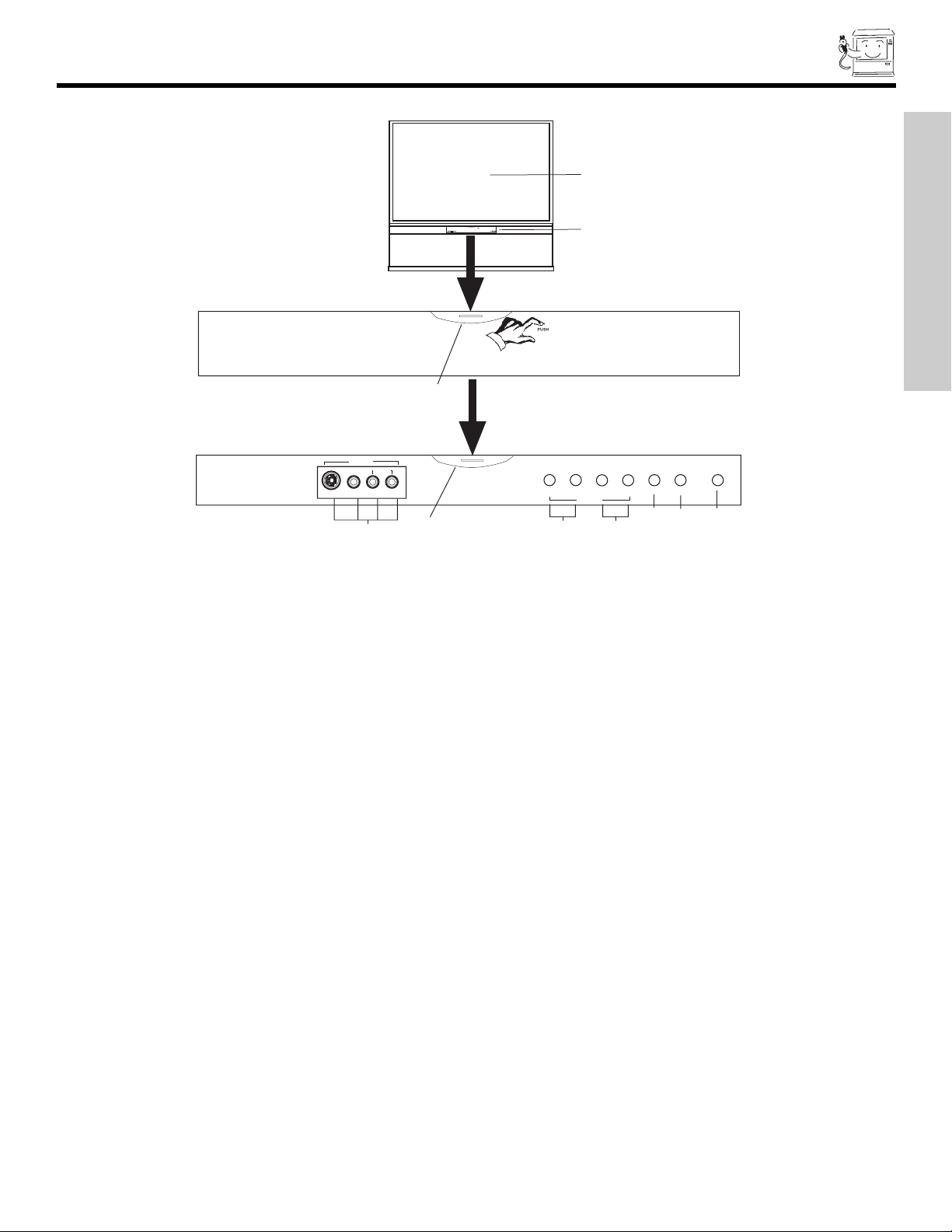
MENU/SELECT button
This button allows you to enter the MENU, making it possible to set TV features to your preference without using the remote. This
button also serves as the SELECT button when in MENU mode.
INPUT/EXIT button
Press this button to display the input menu for Ant A/B and INPUT:1,2,3,4,5. This button also serves as the EXIT button when in
MENU mode.
CHANNEL selector
Press these buttons until the desired channel appears in the top right corner of the TV screen. These buttons also serve as
the cursor down () and up () buttons when in MENU mode.
VOLUME level
Press these buttons for your desired sound level. The volume level will be displayed on the TV screen. These buttons also serve
as the cursor left () and right () buttons when in MENU mode. When the TV power is turned OFF at a volume level 31 or greater,
the volume level will default to 30 when the TV is turned ON. However, if it is set to a level 30 or less, the volume level will be at
the level it was set when the TV is turned ON.
POWER button/ POWER LED
Press this button to turn the TV on or off. This LED light is on during normal operation.
MAGIC FOCUS
Use this button to automatically adjust your picture quality to optimum performance (see page 56).
FRONT INPUT JACKS (INPUT 5)
Use these audio/video jacks for a quick hook-up from a camcorder or VCR to instantly view your favorite show or new recording.
Press the INPUT button and select Input 5. If you have mono sound, insert the audio cable into the left audio jack.
IR RECEIVER Sensor (1)
The screen area acts as one of the IR receivers (remote sensor) of the TV. When using the remote control, point it towards the
screen for best response.
IR RECEIVER Sensor (2)
This is an additional remote sensor for a better remote control range of response.
FIRST TIME USE
FRONT PANEL JACKS AND CONNECTORS
8
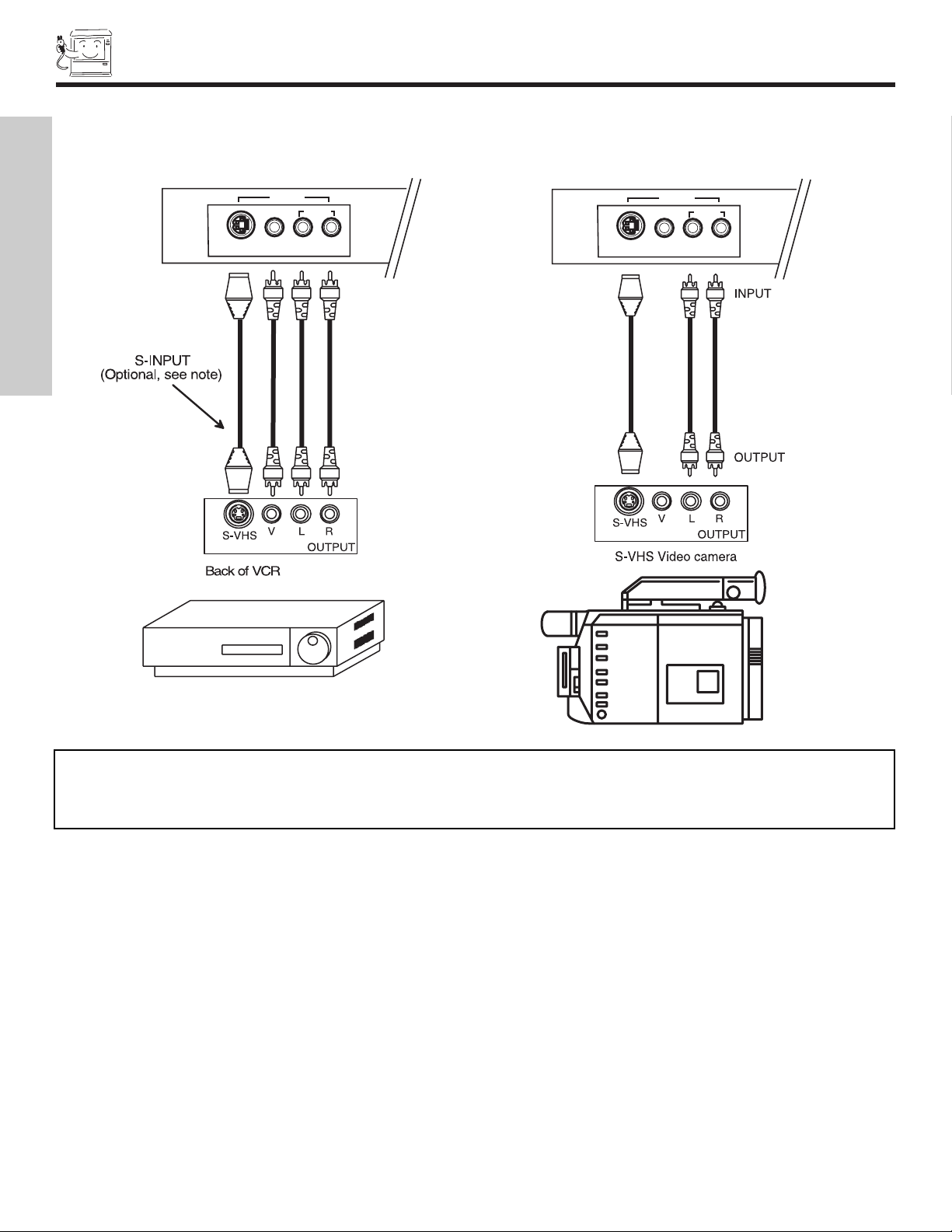
The front panel jacks are provided as a convenience to allow you to easily connect a camcorder or VCR as shown in the following
examples:
NOTE: 1. Completely insert connection cord plugs when connecting to front panel jacks. If you do not, the played back picture
may be abnormal.
2. If you have a S-VHS VCR, use the S-INPUT cable in place of the standard video cable.
3. If you have a mono VCR, insert the audio cable into the left audio jack of your TV.
FIRST TIME USE
S-VIDEO
INPUT 5
VIDEO
AUDIO
L/MONO
INPUT 5
AUDIO
R
S-VIDEO
VIDEO
L/MONO
R
REAR PANEL JACKS
9
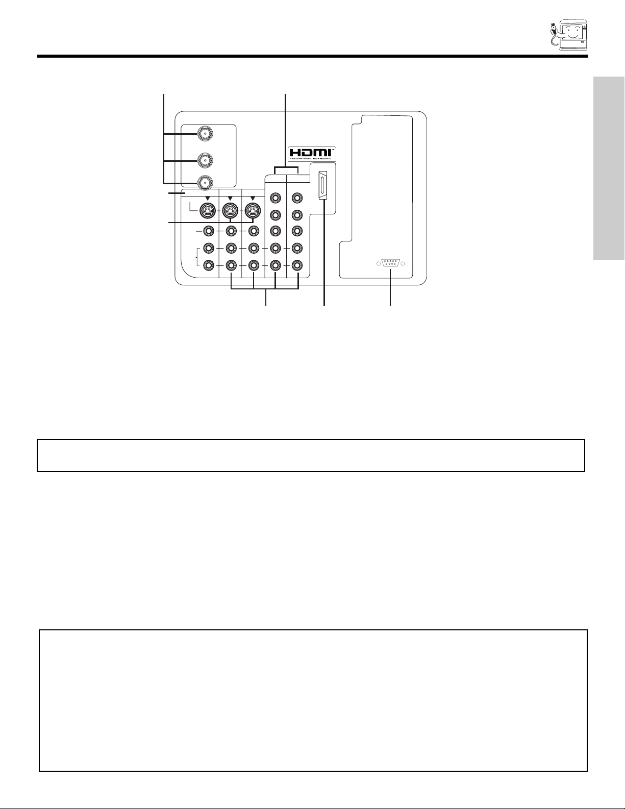
Antenna Input/Output
The remote control allows you to switch between two separate 75-Ohm RF antenna inputs, ANTA and ANT B. ANT A input can
be displayed as a main picture or sub-picture. ANT B can only be displayed as a main picture. (ANT B cannot be displayed as a
sub-picture.) The antenna output labeled “TO CONVERTER” allows the ANT A connection to pass directly to a different source
such as a cable box, only when ANT B is displayed as a main picture.
Audio/Video Inputs 1, 2, 3 and 4
By using the INPUTS button, CURSOR, and SELECT button of the remote control you can select each video source. Use the audio
and video inputs to connect external devices, such as VCRs, camcorders, laserdisc players, DVD players etc. (If you have mono
sound, insert the audio cable into the left audio jack.)
MONITOR OUT
These jacks provide fixed or variable audio and video signals which are used for recording. Use the S-VIDEO Output for high
quality video output (see page 64).
S-VIDEO Inputs 3 and 4
Inputs 3 and 4 provide S-VIDEO (Super Video) jacks for connecting equipment with S-VIDEO output capability.
Component: Y-P
BPR
Inputs
Inputs 1 and 2 provide Y-P
BPR
jacks for connecting equipment with this capability, such as a DVD player or Set Top Box. You may
use composite video signal for both inputs.
NOTE: You may use VIDEO or S-VIDEO inputs to connect to INPUT 3 and 4, but only one of these inputs may be used at a
time.
NOTES: 1. Do not connect composite VIDEO and S-VIDEO to Input 3, 4 or 5 at the same time. S-VIDEO has priority
over VIDEO input.
2.
Your component outputs may be labeled Y, B-Y, and R-Y. In this case, connect the components B-Y output to the TV’s PBinput and
the components R-Y output to the TV’s PRinput.
3. Your component outputs may be labeled Y-CBCR. In this case, connect the component CBoutput to the TV’s PBinput and the
component CRoutput to the TV’s PRinput.
4. It may be necessary to adjust TINT to obtain optimum picture quality when using the Y-PBPR inputs (see page 37).
5. To ensure no copyright infringement, the MONITOR OUT output will be abnormal, when using the Y-PBPRjacks.
6. Input 1 and Input 2 (Y/VIDEO) can be used for composite video and component video input.
FIRST TIME USE
MONITOR OUT INPUT 4 INPUT 3
S-VIDEO
VIDEO
AUDIO
To
Converter
L
R
AUDIO
TO HI-FI
ANT A
ANT B
(MONO) (MONO) (MONO)
(MONO)
INPUT 2 INPUT 1
Y/
VIDEO
P
B
P
R
HDMI 1
Y/
VIDEO
P
B
P
R
RS232C
12345
9876
REAR PANEL JACKS
10
HDMI1 (High Definition Multimedia Interface) (INPUT 1)
About HDMI
HDMI is the next-generation all digital interface for consumer electronics. HDMI enables the secure distribution of uncompressed
high-definition video and multi-channel audio in a single cable. Because digital television (DTV) signals remain in digital format,
HDMI assures that pristine high-definition images retain the highest video quality from the source all the way to your television
screen.
Use the HDMI input for your external devices such as Set-Top-Boxes or DVD players equipped with an HDMI output connection.
HDMI, the HDMI logo and High-Definition Multimedia Interface are trademarks or registered trademarks of HDMI Licensing LLC.
RS232C Input
For use with third party home Audio/Video control systems which are commercially available. Please see your dealer regarding
these “non Hitachi” home control systems (see page 64 to activate this input).
NOTES: 1. The HDMI input is not intended for use with personal computers.
2. Only DTV formats such as 1080i, 720p, 480i and 480p are available for HDMI input.
FIRST TIME USE
11
REAR PANEL CONNECTIONS
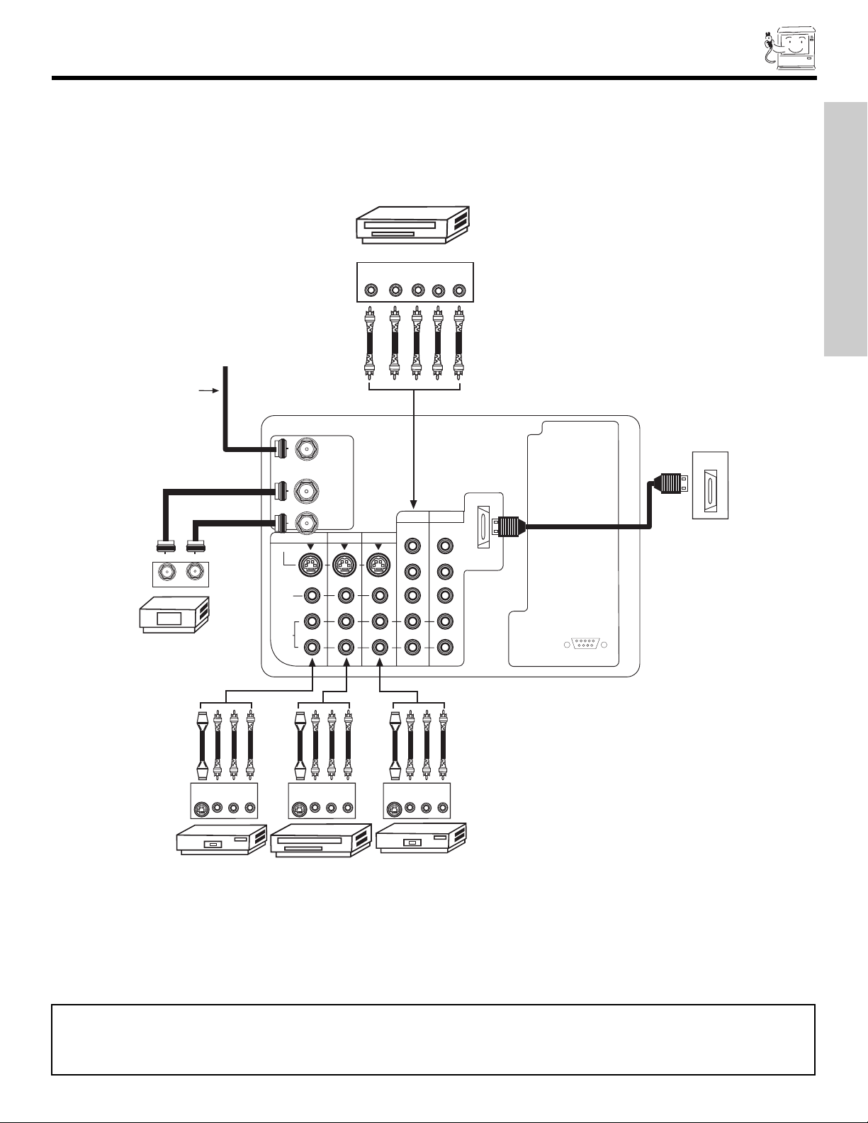
NOTES: 1.
Connect only 1 component to each input jack.
2. Follow connections that pertain to your personal entertainment system.
3. Inputs 1 and 2 can accomodate Composite and Component video signals.
4. Cables are not included with the purchase of this TV, except when noted as “provided”.
TYPICAL FULL-FEATURE SETUP
FIRST TIME USE
Outside antenna or
digital cable
ANT A
To
Converter
DVD Player
YP
B/CBPR/CR
OUTPUT
L R
External Digital
Component with
HDMI output
capability
HDMI
OUT
OUTPUT
INPUT
Cable TV Box
S-VIDEO
VCR #2
INPUT
VLR
ANT B
MONITOR OUT INPUT 4 INPUT 3
S-VIDEO
VIDEO
AUDIO
S-VIDEO
Laserdisc player, VCR,
camcorder, etc.
L
R
OUTPUT
VLR
(MONO)
INPUT 2 INPUT 1
Y/
Y/
VIDEO
VIDEO
P
P
B
P
P
R
(MONO) (MONO) (MONO)
OUTPUT
VLR
S-VIDEO
VCR #1
HDMI 1
B
R
RS232C
12345
9876

12
TIPS ON REAR PANEL CONNECTIONS
• S-VIDEO, Y-PbPr and HDMI connections are provided for high performance laserdisc players, VCRs etc. that have this feature.
Use these connections in place of the standard video connection if your device has this feature.
• If your device has only one audio output (mono sound), connect it to the left audio jack on the television.
• Refer to the operating guide of your other electronic equipment for additional information on connecting your hook-up cables.
•Asingle VCR can be used for VCR #1 and VCR #2, but note that a VCR cannot record its own video or line output (INPUT: 3 in
the example on page 11). Refer to your VCR operating guide for more information on line input-output connections.
•You may use VIDEO or S-VIDEO inputs to connect to Input 3, Input 4 or Input 5, but only one of these may be used at a time.
• Connect only 1 component (VCR, DVD player, camcorder, etc.) to each input jack.
• COMPONENT: Y-PBPR (Input 1 & 2) connections are provided for high performance components, such as DVD players and settop-boxes. Use these connections in place of the standard video connection if your device has this feature. Input 2 accepts
both composite and component video signals.
•Your component outputs may be labeled Y, B-Y, and R-Y. In this case, connect the components B-Youtput to the TV’s PBinput
and the components R-Y output to the TV’s PRinput.
•Your component outputs may be labeled Y-CBCR. In this case, connect the components CBoutput to the TV’s PBinput and
the components CRoutput to the TV’s PRinput.
•You may use composite and component video signals for Inputs 1 and 2.
• It may be necessary to adjust TINT to obtain optimum picture quality when using the Y-PBPRinputs (see page 37).
•
To ensure no copyright infringement, the MONITOR OUT output may be abnormal, when using the
Y-PBP
R
jacks.
• When using an HDMI input from a Set-Top-Box, it is recommended that a 1080i or 720p input signal is used.
FIRST TIME USE

13
CONNECTING EXTERNAL AUDIO SOURCES
REAR PANEL OF TELEVISION
To control the audio level of an external audio amplifier with the remote control, connect the system as shown below.
FIRST TIME USE
ANT A
To
Converter
ANT B
MONITOR OUT INPUT 4 INPUT 3
S-VIDEO
VIDEO
AUDIO
L
R
AUDIO
TO HI-FI
(MONO)
INPUT 2 INPUT 1
Y/
VIDEO
P
B
P
R
(MONO) (MONO) (MONO)
Stereo System Amplifier
Y/
VIDEO
P
B
P
R
L R
INPUT
or DVD Player
HDMI 1
RS232C
12345
9876
14
CONNECTING EXTERNAL VIDEO SOURCES
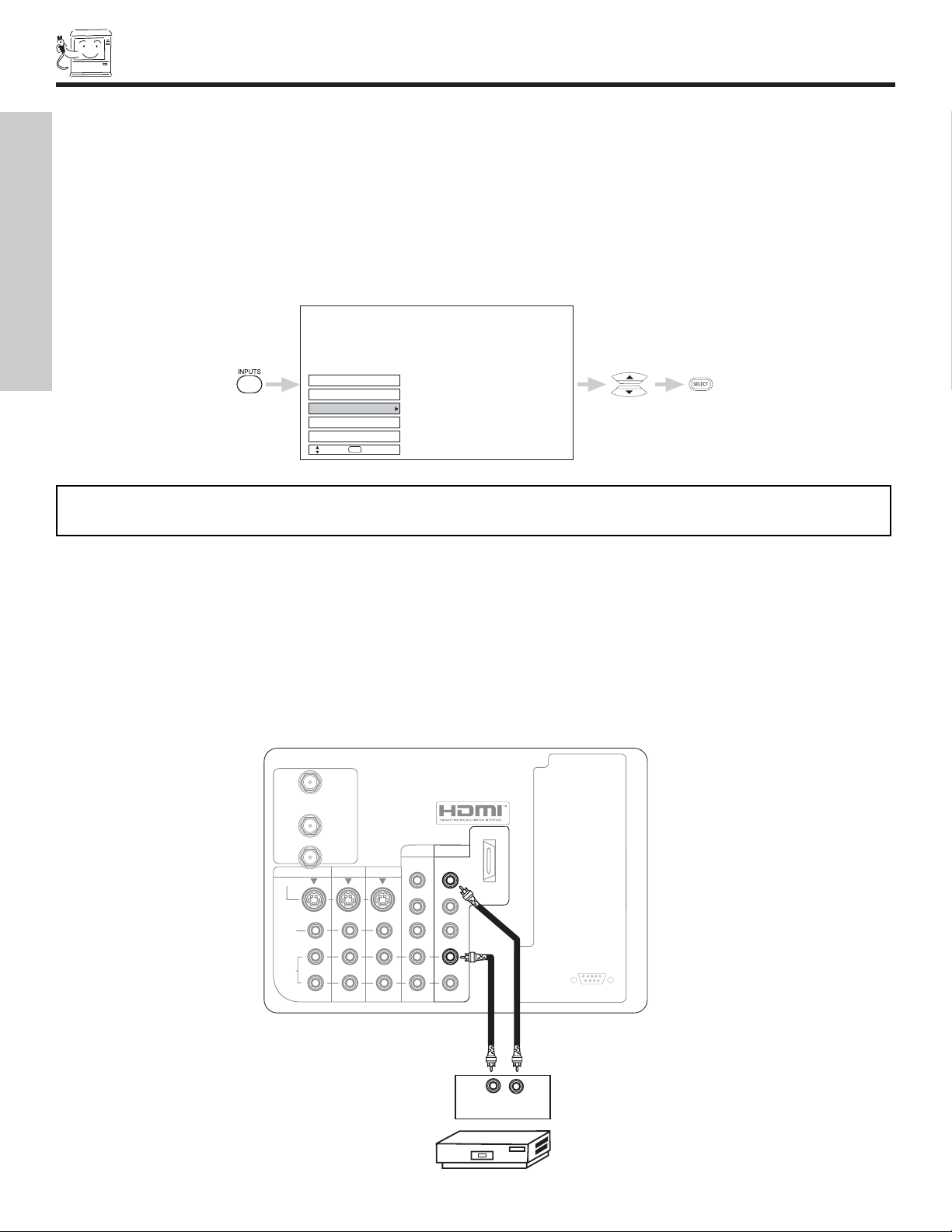
CONNECTING A MONAURAL AUDIO SOURCE TO INPUT1~INPUT5
1. Connect the cable from the VIDEO OUT of the VCR or the laserdisc player to the INPUT (VIDEO) jack, as shown on the TV set
below.
2. Connect the cable from the AUDIO OUT of the VCR or the laserdisc player to the INPUT (MONO)/L(AUDIO) jack.
3. Press the INPUTS button, then select INPUT 1 from the INPUTS menu to view the program from the VCR or the laserdisc player.
The VIDEO OSD label disappears automatically after approximately four seconds.
4. Select Antenna from the INPUTS menu to return to the previous channel.
The exact arrangement you use to connect the VCR, camcorder, laserdisc player, DVD player, or HDTV Set Top Box to your TV set is
dependent on the model and features of each component. Check the owner’s manual of each component for the location of video
and audio inputs and outputs.
The following connection diagrams are offered as suggestions. However, you may need to modify them to accommodate your particular assortment of components and features. For best performance, video and audio cables should be made from coaxial shielded
wire.
Before Operating External Video Source
Connect an external source to the INPUT terminal, then press the INPUTS button to show the INPUTS menu. Use the CURSOR buttons to select the Antenna and Input of your choice. Then press the SELECT button to confirm your choice (see page 22).
Input 2
Input 1
Ant A
Ant B
Input 5
Move
SEL
Select
NOTE: When the TV is set to VIDEO and a video signal is not received from the VIDEO INPUT JACK on the back panel
of the TV (i.e., VCR/laserdisc player, etc. is not connected or the video device is OFF), the set will appear to be OFF.
FIRST TIME USE
ANT A
To
Converter
HDMI 1
ANT B
MONITOR OUT INPUT 4 INPUT 3
S-VIDEO
VIDEO
AUDIO
L
R
AUDIO
TO HI-FI
(MONO)
INPUT 2 INPUT 1
Y/
Y/
VIDEO
VIDEO
P
P
B
P
P
R
(MONO) (MONO) (MONO)
B
R
RS232C
12345
9876
Audio Video
OUTPUT
VCR

15
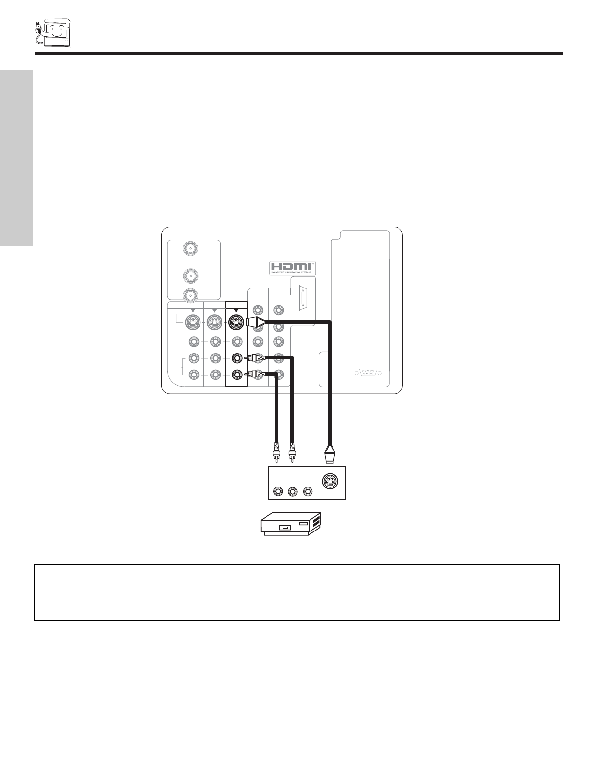
CONNECTING EXTERNAL VIDEO SOURCES
CONNECTING A STEREO SOURCE TO INPUT1~INPUT5
1. Connect the cable from the VIDEO OUT of the VCR or the laserdisc player to the INPUT (VIDEO) jack, as shown on the TV set
below.
2. Connect the cable from the AUDIO OUT R of the VCR or the laserdisc player to the INPUT (AUDIO/R) jack.
3. Connect the cable from the AUDIO OUT L of the VCR or the laserdisc player to the INPUT (AUDIO/L) jack.
4. Press the INPUTS button, then select INPUT 3 from the INPUTS menu to view the program from the VCR or laserdisc player.
The VIDEO OSD label disappears automatically after approximately four seconds.
5. Select Antenna from the INPUTS menu to return to the previous channel.
NOTES: 1. Completely insert the connection cord plugs when connecting to rear panel jacks. The picture and sound that is
played back will be abnormal if the connection is loose.
2. A single VCR can be used for VCR #1 and VCR #2 (see page 11), but note that a VCR cannot record its own video
or line output. Refer to your VCR operating guide for more information on line input-output connections.
12345
9876
RS232C
ANT A
S-VIDEO
R
L
VIDEO
AUDIO
(MONO)
(MONO) (MONO) (MONO)
P
R
P
B
Y/
VIDEO
Y/
VIDEO
P
R
P
B
MONITOR OUT INPUT 4 INPUT 3
INPUT 2 INPUT 1
HDMI 1
ANT B
VCR
OUTPUT
RLV
AUDIO
TO HI-FI
To
Converter
FIRST TIME USE
16
CONNECTING EXTERNAL VIDEO SOURCES
CONNECTING AN S-VIDEO SOURCE TO INPUT 3, 4 AND 5
1. Connect the cable from the S-VIDEO OUT of the VCR or the laserdisc player to the INPUT (S-VIDEO) jack, as shown on the TV
set below.
2. Connect the cable from the AUDIO OUT R of the VCR or the laserdisc player to the INPUT (AUDIO/R) jack.
3. Connect the cable from the AUDIO OUT L of the VCR or the laserdisc player to the INPUT (AUDIO/L) jack.
4. Press the INPUTS button, then select INPUT 3 from the INPUTS menu to view the program from the VCR or laserdisc player.
The VIDEO OSD label disappears automatically after approximately four seconds.
5. Select Antenna from the INPUTS menu to return to the previous channel.
NOTES: 1. Completely insert the connection cord plugs when connecting to rear panel jacks. The picture and sound that is
played back will be abnormal if the connection is loose.
2. A single VCR can be used for VCR #1 and VCR #2 (see page 11), but note that a VCR cannot record its own video
or line output. Refer to your VCR operating guide for more information on line input-output connections.
FIRST TIME USE
ANT A
To
Converter
HDMI 1
ANT B
MONITOR OUT INPUT 4 INPUT 3
S-VIDEO
VIDEO
AUDIO
L
R
AUDIO
TO HI-FI
(MONO)
INPUT 2 INPUT 1
Y/
Y/
VIDEO
VIDEO
P
P
B
P
P
R
(MONO) (MONO) (MONO)
B
R
RS232C
12345
9876
RLV
S-VIDEO
VCR
17
CONNECTING EXTERNAL VIDEO SOURCES
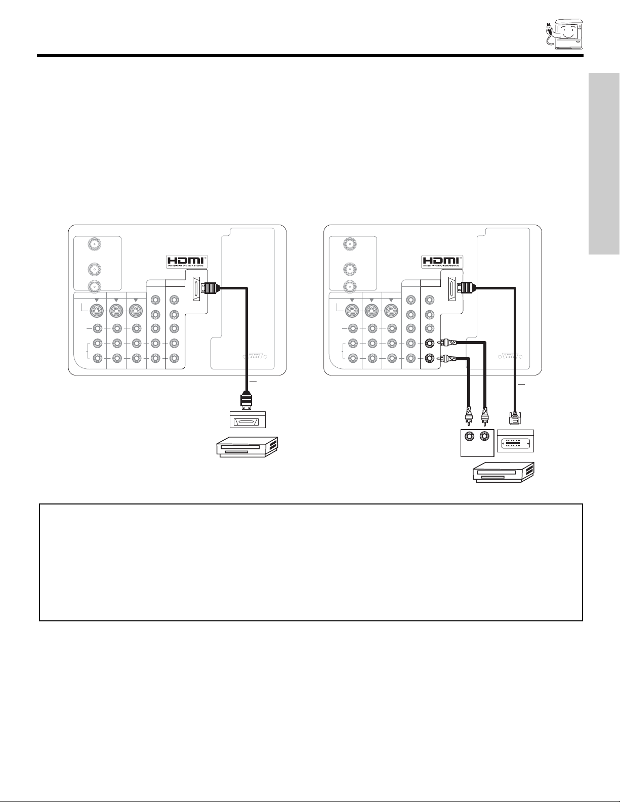
CONNECTING A COMPONENT SOURCE WITH HDMI or DVI CAPABILITY TO INPUT 1
1. Connect the HDMI or DVI to HDMI connection cable from the output of the HDTV set top box or DVD player to the HDMI input as
shown on the TV set below. When using a component with DVI output, you also have to connect the AUDIO OUT (R/L) of the
component to the AUDIO IN (R/L) of INPUT 1.
2. Press the INPUTS button, then select INPUT 1 from the INPUTS menu to view the program from the HDTV set top box or DVD
player. The VIDEO OSD label disappears automatically after approximately four seconds.
3. Select Antenna from the INPUTS menu to return to the previous channel.
12345
9876
RS232C
12345
9876
RS232C
ANT A
S-VIDEO
R
L
VIDEO
AUDIO
(MONO)
(MONO) (MONO) (MONO)
P
R
P
B
Y/
VIDEO
Y/
VIDEO
P
R
P
B
MONITOR OUT INPUT 4 INPUT 3
INPUT 2 INPUT 1
HDMI 1
ANT B
DVD Player or HDTV STB
DVI to HDMI
Cable
AUDIO
TO HI-FI
ANT A
S-VIDEO
R
L
VIDEO
AUDIO
(MONO)
(MONO) (MONO) (MONO)
P
R
P
B
Y/
VIDEO
Y/
VIDEO
P
R
P
B
MONITOR OUT INPUT 4 INPUT 3
INPUT 2 INPUT 1
HDMI 1
ANT B
HDMI Output
DVD Player or HDTV STB
HDMI Cable
AUDIO
TO HI-FI
RL
AUDIO OUT
DIGITAL OUTPUT
HDMI-HDMI
DVI-HDMI
To
Converter
To
Converter
NOTES: 1. Completely insert the connection cord plugs when connecting to rear panel jacks. The picture and sound that is
played back will be abnormal if the connection is loose.
2. The HDMI input on INPUT 1 contains the copy protection system called High-bandwidth Digital Content
Protection (HDCP). HDCP is a cryptographic system that encrypts video signals when using HDMI connections to
prevent illegal copying of video contents.
3. HDMI is not a “NETWORK” technology. It establishes a one-way point-to-point connection for delivery of
uncompressed video to a display.
4. The connected digital output device controls the HDMI interface so proper set-up of device user settings determines
final video appearance.
FIRST TIME USE
18
CONNECTING EXTERNAL VIDEO SOURCES
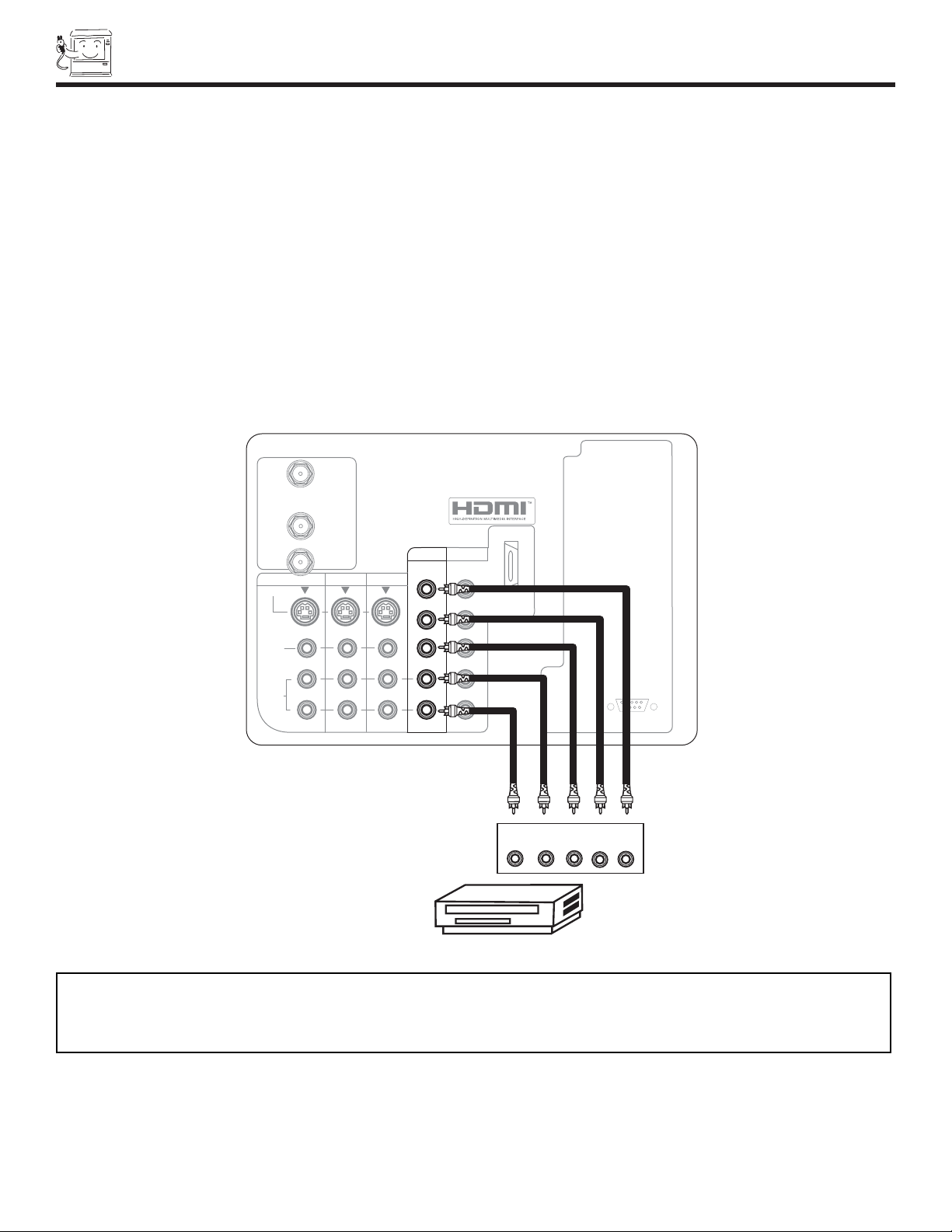
CONNECTING A COMPONENT SOURCE TO INPUT 1 OR 2: Y-PBPR.
1. Connect the cable from the Y OUT of the Laserdisc/DVD player or HDTV set top box to the INPUT (Y) jack, as shown on the TV
set below.
2. Connect the cable from the CB/PBOUT or B-Y OUT of the Laserdisc/DVD player or HDTV set top box to the INPUT (PB)jack.
3. Connect the cable from the CR/PROUT or R-Y OUT of the laserdisc/DVD player or HDTV set top box to the INPUT (PR) jack.
4. Connect the cable from the AUDIO OUT R of the Laserdisc/DVD player or HDTV set top box to the INPUT (AUDIO/R) jack.
5. Connect the cable from the AUDIO OUT L of the Laserdisc/DVD player or HDTV set top box to the INPUT (AUDIO/L) jack.
6. Press the the INPUTS button, then select INPUT 2 from the INPUTS menu to view the program from the Laserdisc/DVD player
or HDTV set top box. The VIDEO OSD label disappears automatically after approximately four seconds.
7. Select Antenna from the INPUTS menu to return to the previous channel.
NOTES: 1. Completely insert the connection cord plugs when connecting to rear panel jacks. The picture and sound that is
played back will be abnormal if the connection is loose.
2. See page 12 for tips on REAR PANELCONNECTIONS.
DVD Player
12345
9876
RS232C
ANT A
S-VIDEO
R
L
VIDEO
AUDIO
(MONO)
(MONO) (MONO) (MONO)
P
R
P
B
Y/
VIDEO
Y/
VIDEO
P
R
P
B
MONITOR OUT INPUT 4 INPUT 3
INPUT 2 INPUT 1
HDMI 1
ANT B
OUTPUT
P
R
P
B
Y
R L
AUDIO
TO HI-FI
To
Converter
19
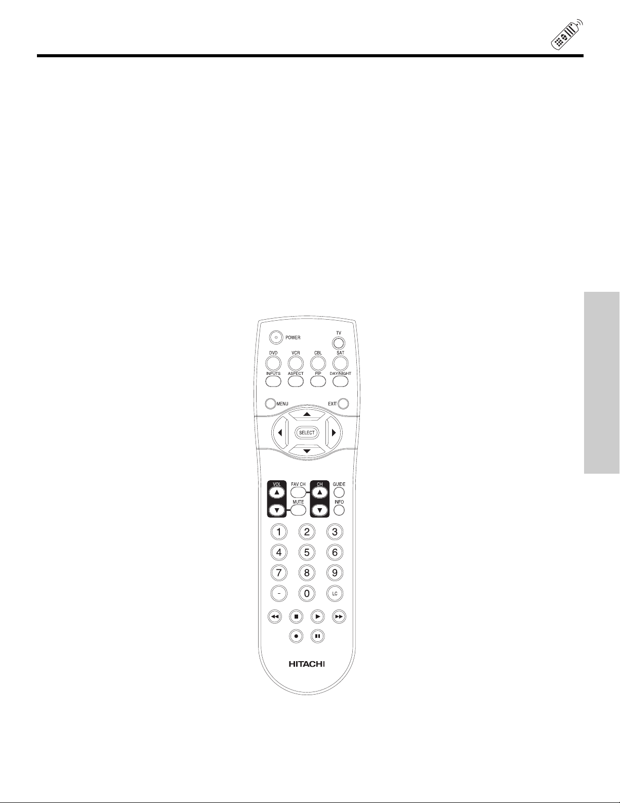
THE REMOTE CONTROL
In addition to controlling all the functions on your HITACHI Projection TV, the new remote control is designed to operate different
types of VCRs, CATV (Cable TV) converters, set-top-box, satellite receiver (SAT) and DVD players with one touch. Basic operation keys are grouped together in one area.
To operate your TV, point the remote control at the screen of the TV and press the TV button. The remote will now control your
television.
To operate your VCR, point the remote at the remote sensor of the VCR and press the VCR button. The remote will now control
your VCR (see page 31 for instructions on how to program the remote to control your VCR).
To operate your cable box, point the remote at the remote sensor of the cable box and press the CABLE (CBL) button. The
remote will now control your cable box (see page 28 for instructions on how to program the remote to control your cable box).
To operate your set-top-box or satellite receiver, point the remote at the remote sensor of the set-top-box or satellite receiver and
press the SAT button. The remote will now control your set-top-box or satellite receiver. If you have a satellite receiver, use this
button to program your satellite receiver (see page 29 for instructions on how to program the remote to control your SAT).
To operate your DVD player, point the remote at the remote sensor of the DVD player and press the DVD button. The remote
will now control your DVD player (see page 30 for instruction on how to program the remote to control your DVD
player).
THE REMOTE CONTROL
20
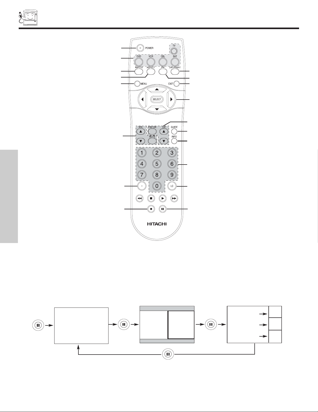
HOW TO USE THE REMOTE TO CONTROL YOUR TV
POWER button
Press this button to turn the TV set on or off when the remote is in TV mode. (See page 19 for instructions on how to set the remote
control to TV mode.)
MODE buttons
These buttons allow the remote to control your TV, VCR, DVD, Cable box/Satellite box depending on which button is pressed.
PAUSE button
Press the PAUSE button to freeze the picture. Press the EXIT button to return the picture to motion. Press the PAUSE button
repeatedly to cycle through the three different freeze modes (see page 27).
DAY/NIGHT button
Press this button to toggle between Day and Night picture mode settings. Select Day for day time viewing with more brightness
and contrast to compete with room light. Select Night for night time viewing with less brightness and contrast for a more detailed
picture (see page 36 for settings changes).
THE REMOTE CONTROL
Freeze
Freeze
Freeze
Freeze
Freeze
21
HOW TO USE THE REMOTE TO
CONTROL YOUR TV
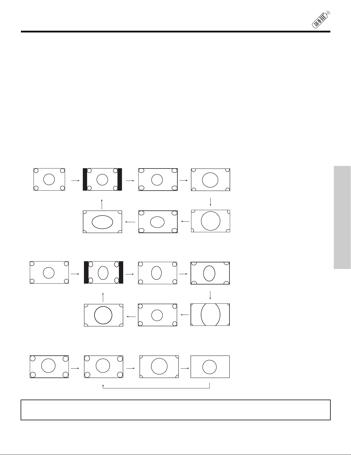
ASPECT button
Press this button to quickly change the picture format ASPECT ratio.
Depending on the input signal format received, the picture format ratio allows you to adjust the images through the following options.
4:3 STANDARD Use this aspect mode to display conventional (4:3) images. Side panels (gray areas) are placed to the
left and right of the image to preserve the original aspect ratio of the source. Note: Use this mode for
only 15% of your total viewing time to prevent uneven aging of the phosphors. Phosphors in the lighted
area of the picture will age more rapidly than the gray areas.
4:3 EXPANDED Use this aspect mode to display conventional (4:3) sources by linearly increasing image expansion from
the center towards the edges of the display area in order to fill it.
4:3 Zoom1/Zoom2 Use these aspect modes to zoom in on conventional (4:3) sources.
16:9 STANDARD Use this aspect mode to display 16:9 sources like HDTV and DVD’s preserving the original 16:9 aspect
ratio.
16:9 Zoom Use this aspect to Zoom-in once while in 16:9 aspect.
(1) NTSC/480i/480P Input
(2) 480i/480P Input
(3) 720P/1080i Input
4:3
INPUT
4:3 EXPANDED
4:3 ZOOM1
4:3 ZOOM2
16:9 STANDARD
4:3 STANDARD
INPUT
4:3 EXPANDED
4:3 ZOOM1
4:3 ZOOM2
16:9 STANDARD
4:3 STANDARD
INPUT
16:9
16:9 STANDARD 16:9 ZOOM
16:9 ZOOM
16:9 ZOOM
16:9
4:3 EXPANDED
NOTE: The Aspect Style setting you select for an ANT input will automatically be set for the other ANT inputs. However, all
five video inputs have independent Aspect Style settings.
THE REMOTE CONTROL
22
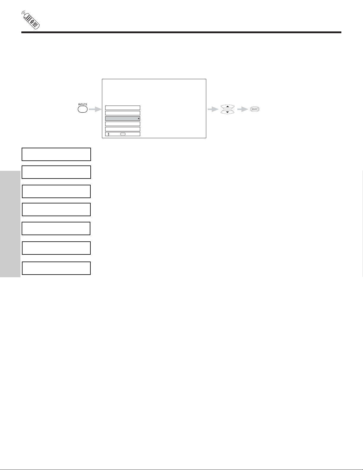
INPUTS button
When the remote control is in TV mode, press this button to access the INPUTS menu. Use the CURSOR and SELECT buttons
to select the inputs that are being used. Pressing the INPUTS button repeatedly will also cycle through the Inputs menu items.
Then press the SELECT button to select.
Input 2
Input 1
Ant A
Ant B
Input 5
Move
SEL
Select
Select to choose Antenna A.
Select to choose Antenna B.
Ant A
Ant B
Select to choose Input 1 for Video 1.
Input 1
Select to choose Input 2 for Video 2.
Input 2
Select to choose Input 3 for Video 3.
Input 3
Select to choose Input 5 for Video 5.
Input 5
Select to choose Input 4 for Video 4.
Input 4
HOW TO USE THE REMOTE TO
CONTROL YOUR TV
THE REMOTE CONTROL

23
HOW TO USE THE REMOTE TO
CONTROL YOUR TV
PICTURE-IN-PICTURE button
See separate section on pages 25-27 for a description.
MENU button
The MENU button will start the On-Screen Display.
GUIDE button [Cable Box (CBL), Satellite Receiver (SAT)/Set-Top-Box (STB) mode only]
The use of this button is only applicable when the remote control is in (CBL) and (SAT/STB) mode. Press this button to access the
Channel Guide of the (CBL), and (SAT/STB).
EXIT button
This button will exit all On-Screen Displays.
CURSOR buttons/SELECT button
All the On-Screen Display features can be set or adjusted by using the CURSOR buttons and the SELECT button, except for
numeric entries. Press the CURSOR buttons toward desired direction and press the SELECT button to select.
INFO button
Press this button when you want to check the channel being received, the picture source, if the channel has stereo (ST) or second
audio program (SAP), the time, CHANNEL ID and if the TIMER is set.
Main Picture Source
Time
Aspect
Mode
Day/Night
Mode
Closed
Captioning
Event Timer
3:32 PM
Ant A 22
ST Stereo
R
Day Off HD 1080i 4:3 Expanded
--:-- AM --:-- PM
View
CC
Audio Broadcast
Broadcast Rating
INFO
When an S-VIDEO
Input is connected to
VIDEO: 3.
When a
COMPONENT
VIDEO: Y-PBPRInput
is connected to
VIDEO: 1.
3:32 PM
S-IN: 3
VID 3
3:32 PM
YPBPR: 1
VID: 1
NOTES: 1. The Sleep Timer info will show momentarily after releasing INFO button.
2. Press the INFO button again or the EXIT button to return to normal viewing.
THE REMOTE CONTROL
INFO
INFO
 Loading...