


LCD REAR PROJECTION
TELEVISION
Operating Guide for 50VS69A
55VS69A and 62VS69A
IMPORTANT SAFETY INSTRUCTIONS
FIRST TIME USE
THE REMOTE
ON-SCREEN DISPLAY
LAMP REPLACEMENT
USEFUL INFORMATION
LICENSE AGREEMENT
APPENDIXES
INDEX
.............................................................................................................................................76
As an Ener
Hitachi, Ltd. has determined
that this product meets the
Ener
gy Star®guidelines for
ener
gy ef
ficiency
.......................................................................................................................
CONTROL
............................................................................................................................74-75
gy Star®Partner
.
........................................................................................................
............................................................................................................ 31
.............................................................................................................56
..........................................................................................................
..................................................................................................................65-73
,
.......................................................................................
2-3
4-18
19-30
-55
-59
60-
64
Important Safety Instructions
SAFETY POINTS YOU SHOULD KNOW ABOUT
YOUR HITACHI LCD REAR PROJECTION
TELEVISION
Our reputation has been built on the quality,
performance, and ease of service of HITACHI
televisions.
Safety is also foremost in our minds in the design of
these units. To help you operate these products
properly, this section illustrates safety tips which will be
of benefit to you. Please read it carefully and apply the
knowledge you obtain from it to the proper operation of
your HITACHI television.
Please fill out your warranty card and mail it to
HITACHI. This will enable HITACHI to notify you
promptly in the improbable event that a safety problem
should be discovered in your product model.
Follow all warnings and instructions marked on
this television.
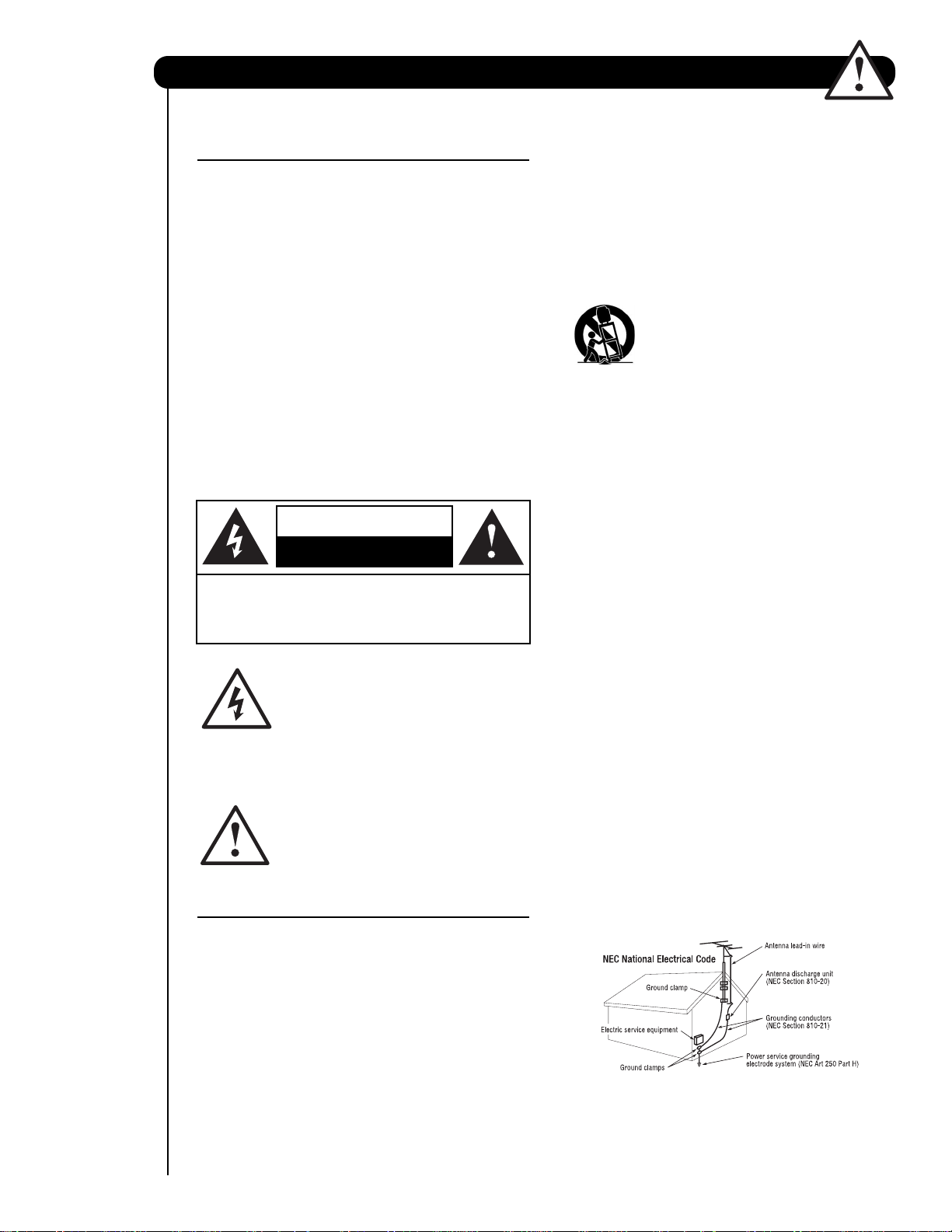
CAUTION
RISK OF ELECTRIC SHOCK
DO NOT OPEN
CAUTION: TO REDUCE THE RISK OF ELECTRIC SHOCK,
DO NOT REMOVE COVER (OR BACK).
NO USER SERVICEABLE PARTS INSIDE.
REFER SERVICING TO QUALIFIED SERVICE PERSONNEL.
The lightning flash with arrowhead symbol,
within an equilateral triangle, is intended to
alert the user to the presence of
uninsulated “dangerous voltage” within the
product’s enclosure that may be of a sufficient
magnitude to constitute a risk of electric shock to a
person.
The exclamation point within an equilateral
triangle, is intended to alert the user to the
presence of important operating and
maintenance (servicing) instructions in the
literature accompanying the appliance.
READ BEFORE OPERATING EQUIPMENT
Follow all warnings and instructions marked on this
television.
1. Read these instructions.
2. Keep these instructions.
3. Heed all warnings.
4. Follow all instructions.
5. Do not use this apparatus near water.
6. Clean only with a dry cloth.
7. Do not block any ventilation openings. Install in
accordance with the manufacturer’s instructions.
8. Do not install near any heat sources such as
radiators, heat registers, stoves, or other apparatus
(including amplifiers) that produce heat.
9. Do not defeat the safety purpose of the polarized or
2
grounding-type plug. A polarized plug has two
blades with one wider than the other. A grounding
type plug has two blades and a third grounding
prong. The wide blade or the third prong are
provided for your safety. If the provided plug does
not fit into your outlet, consult an electrician for
replacement of the obsolete outlet.
10. Protect the power cord from being walked on or
pinched particularly at plugs, convenience
receptacles, and the point where they exit from the
apparatus.
11. Only use the attachments/accessories specified by
the manufacturer.
12. Use only with the cart, stand, tripod,
bracket, or table specified by the
manufacturer, or sold with the
apparatus. When a cart is used, use
caution when moving the cart/apparatus
combination to avoid injury from tip-over.
13. Unplug this apparatus during lightning storms or
when unused for long periods of time.
14. Refer all servicing to qualified service personnel.
Servicing is required when the apparatus has been
damaged in any way, such as power-supply cord or
plug is damaged, liquid has been spilled or objects
have fallen into apparatus, the apparatus has been
exposed to rain or moisture, does not operate
normally, or has been dropped.
15. Televisions are designed to comply with the
recommended safety standards for tilt and stability.
Do not apply excessive pulling force to the front, or
top, of the cabinet which could cause the product
to overturn resulting in product damage and/or
personal injury.
16. Follow instructions for wall, shelf or ceiling
mounting as recommended by the manufacturer.
17. An outdoor antenna should not be located in the
vicinity of overhead power lines or other electrical
circuits.
18. If an outside antenna is connected to the receiver
be sure the antenna system is grounded so as to
provide some protection against voltage surges and
built up static charges. Section 810 of the National
Electric Code, ANSI/NFPA No. 70-1984, provides
information with respect to proper grounding for the
mast and supporting structure, grounding of the
lead-in wire to an antenna discharge unit, size of
grounding connectors, location of antennadischarge unit, connection to grounding electrodes
and requirements for the grounding electrode.
Note to the CATV system installer: This reminder is
provided to call the CATV system installer’s attention to
Article 820-44 of the NEC that provides guidelines for
proper grounding and, in particular, specifies that the
cable ground shall be connected to the grounding
system of the building, as close to the point of cable
entry as practical.
Important Safety Instructions
Power source
This television is designed to operate on 120 volts
60 Hz, AC curr
60 Hz outlet. The power cord is used as the disconnect
device and shall rem ain readily operable.
T
o prevent electric shock, do not use the television’
(polarized) plug with an extension cor
other outlet unless the blades and ground terminal can
be fully inserted to prevent blade exposur
Never connect the television to 50 Hz, direct current, or
anything other than the specified voltage.
Caution
unplug the television and call your authorized dealer or
service center.
Caution
Adjust only those controls that ar
instructions, as improper changes or modifications not
essly appr
expr
warranty.
War
ning
•To reduce the risk of fire or electric shock, do not
expose this apparatus to rain or moistur
•
The television should not be exposed to dripping or
splashing and objects filled with liquids, such as
vases, should not be placed on the television.
War
ning
•
Do not place any objects on the top of the television
which may fall or cause a child to climb to r
objects.
ent. Insert the power cord into a 120 volt
s
d, recept acle, or
e.
Never r
emove the back cover of the
television as this can expose you to very
high voltages and other hazar
television does not operate properly
e cover
oved by
HIT
ACHI
could void the user’
ds. If the
,
ed in the
e.
etrieve
s
the
Public viewing of copyrighted material
Public viewing of programs broadcast by TV stations
and cable companies, as well as pr
sources, may requir
broadcaster or owner of the video pr
oduct incorporates copyright protection
This pr
technology that is protected by U.S. patents and other
intellectual property rights. Use of this copyright
protection technology must be authorized by
Macrovision Corporation, and is intended for home and
other limited consumer uses only unless otherwise
authorized by Macr
disassembly is prohibited.
Note
This digital television is capable of receiving analog
basic, digital basic and digital pr
programming by direct connection to a cable system
providing such pr
by your cable operator is r
digital programming. Certain advanced and interactive
digital cable services such as video-on-demand, a cable
operat or’
television services may requir
For mor
Note
•
•Model and serial numbers ar
Lead/Mercury Notice
Hg
mer
accordanc e with applicable envir
lamp recycling and disposal information, go to
www.lamprecycle.or
disposal information contact your local government
agency or
Electronic Industries Alliance at
US) or the Electr
www.epsc.ca
FOR MORE INFORMA
s enhanced pr
e information call your local cable company
There ar
television.
of the television.
e no user serviceable parts inside the
This pr
oduct contains lead and a lamp that contains
cury. Dispose of this product and its lamp in
www
e prior authorization from the
ovision. Reverse engineering or
ogramming. A CableCARD pr
equir
ogram guide and data-enhanced
g. For pr
.eRecycle.org
onic Product Stewardship Canada at
(in Canada).
TION, CALL 1-800-HIT
ograms from other
ogram material.
emium cable television
ovided
ed to view encrypted
e the use of a set-top box.
.
e indic at ed on back side
onmental laws. For
oduct recycling and
(in California), the
www.eiae.org(in the
ACHI.
3
Accessories
Check to make sure you have the following accessories before disposing of the packing material.
First time use
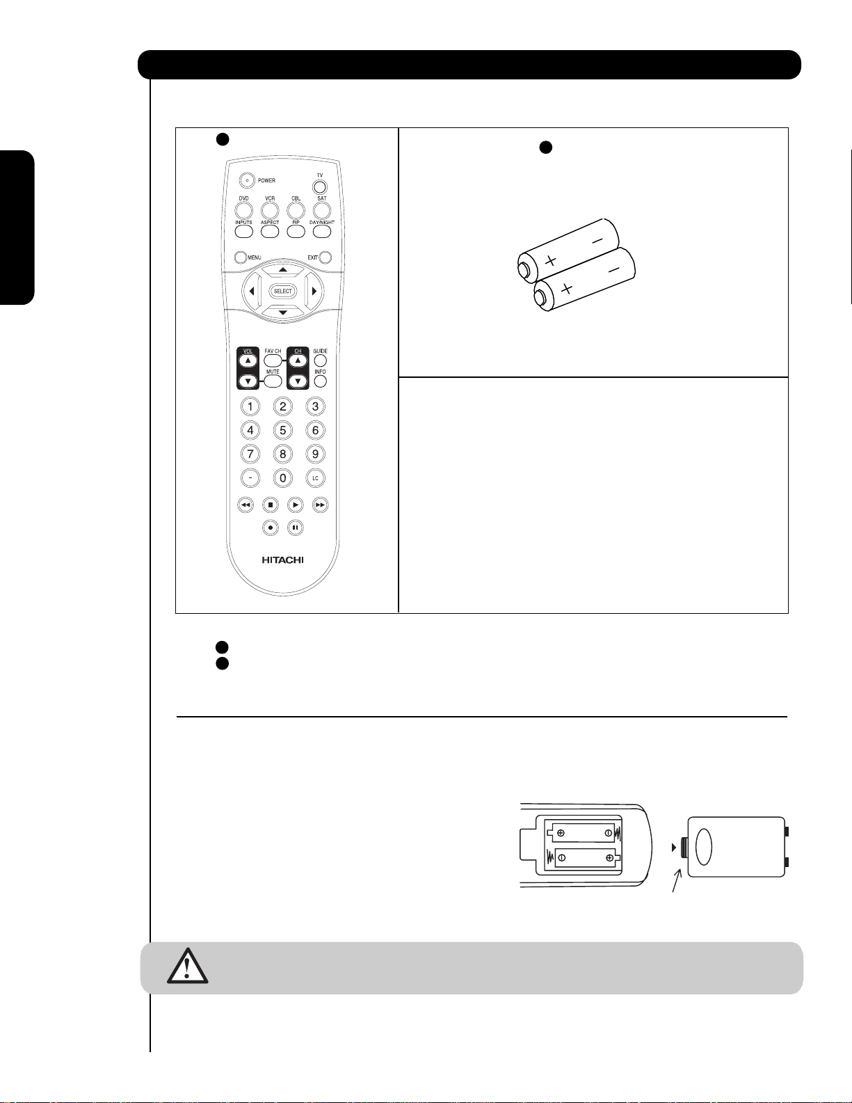
1 Remote Contr
ol
2 T
wo “AA” size,
1.5V batteries
For US models: For optional accessories,
please access our website at
www.hitachi.us/tv
1 Remote Contr
wo “AA” size, 1.5V batteries (For Remote Contr
2 T
REMOTE CONTROL BATTERY INSTALLATION AND REPLACEMENT
1.
Open the battery cover of the remote control by Lift up on tab to remove back cover.
2.
Insert two new “AA” size batteries for the remote contr
springs and lift them out.
3. Match the batteries to the (+) and (-) marks in the battery
compartment.
4.
Insert the bottom of the battery
compartment first, push towards the springs and insert the
top of the battery
battery into the battery compartment.
5. Replace the cover.
CAUTION:Do not insert batteries with the µ¶and µ ¶ polarities reversed as this may cause the batteries
to swell or rupture resulting in leakage.
ol Unit CLU-4351UG2 (Part No. HL02072). 2
ol. When r
, the (-) side, into the battery
, the (+) side, into place. Do not for
ce the
ol Unit).
eplacing old batteries, push them towards the
Bottom View (Remote Control)
Lift up on tab to r
emove back cover.
4
How to set up your new HITACHI Projection Television
ANTENNA
Unless your LCD Rear PTV is connected to a cable TV system or to a centralized antenna system, a good outdoor
TV antenna is recommended for best performance. However, if you are located in an exceptionally good signal
area that is free from interference and multiple image ghosts, an indoor antenna may be sufficient.
LOCATION
Select an area where sunlight or bright indoor illumination will not fall directly on the picture screen. Also, be sure
that the location selected allows a free flow of air to and from the perforated back cover of the set. To avoid
cabinet warping, cabinet color changes, and increased chance of set failure, do not place the TV where
temperatures can become excessively hot, for example, in direct sunlight or near a heating appliance, etc. When
using your LCD Rear PTV against a wall, keep it at least 10cm (4 inches) from the wall.
NOTE: Your new HDTV has a built-in high definition television signal processor. This television includes a fan
to cool the processor. The sound of moving air from the fan is normal and may be noticeable in very
quiet environments.
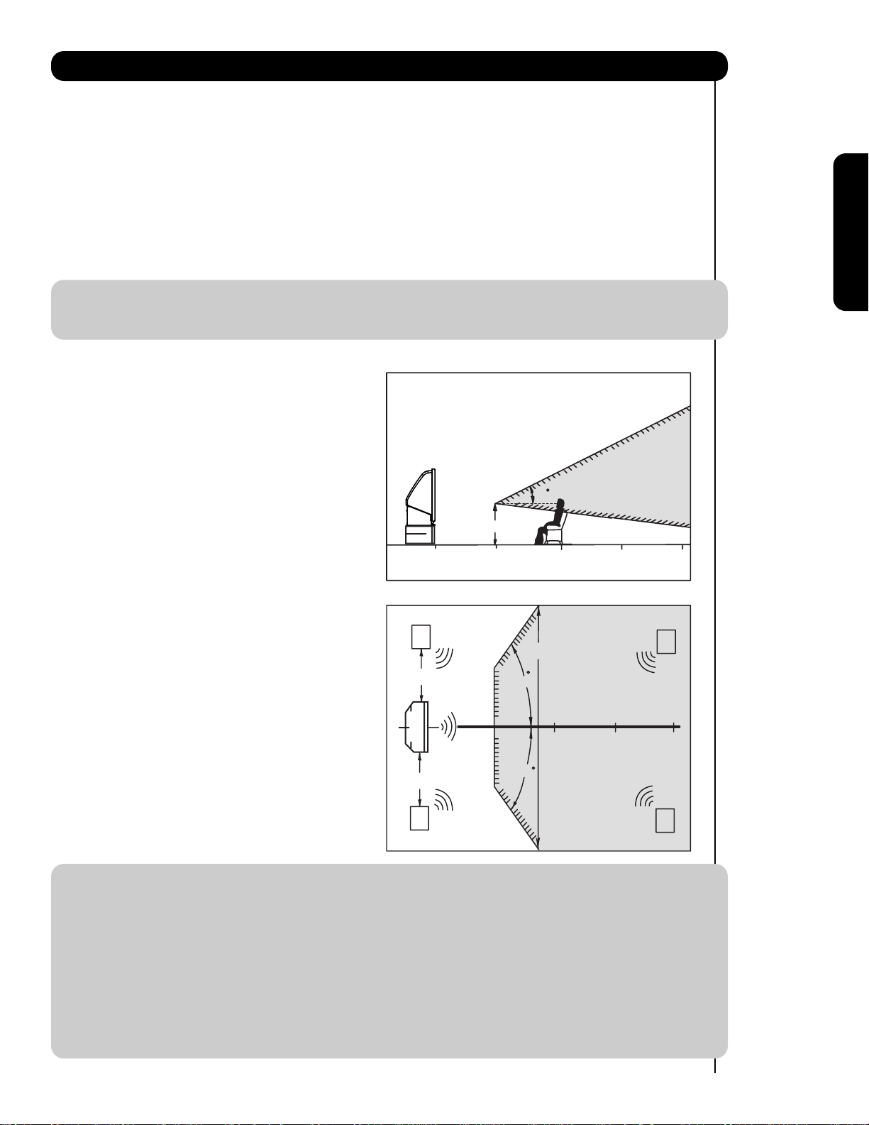
VIEWING
The major benefit of the HITACHI LCD Rear PTV is its
large viewing screen. To see this large screen at its best,
test various locations in the room to find the optimum
spot for viewing.
First time use
The best picture is seen by sitting directly in front of the
TV and about 10 to 18 feet from the screen. Picture
brightness decreases as the viewer moves to the left
20
BEST
VERTICAL VIEWING
ANGLE
and right of the receiver.
3'
During daylight hours, reflections from outside light may
appear on the screen. If so, drapes or screens can be
0'
5'
10'
15'
used to reduce the reflection or the TV can be located in
a different section of the room.
If the TV’s audio output will be connected to a Hi-Fi
system’s external speakers, the best audio performance
will be obtained by placing the speakers equidistant
from each side of the receiver cabinet and as close as
possible to the height of the picture screen center. For
best stereo separation, place the external speakers at
R
4" Minimum
20'
50
S
BEST
HORIZONTAL
least four feet from the side of the TV, place the
surround speakers to the side or behind the viewing
area. Differences in room sizes and acoustical
environments will require some experimentation with
speaker placement for best performance.
4" Minimum
L
5'
10'
VIEWING ANGLE
50
15'
20'
S
IMPORTANT NOTES:
1. Since LCD Rear PTV incorporates a high pressure lamp to display an image, it may take about one
minute for the picture to become stable, after the power has been turned on. After extended use, the
picture may darken, the color may look unusual, or the lamp “goes out,” (burns out). You may hear a
“pop” sound when the lamp “goes out.” These are common characteristics of the lamp, and should
not be considered defective.
2. LCD Rear PTV incorporates an advanced cooling fan system to prevent from overheating. If you hear
the cooling fan, it should not be considered defective.
3. If you hear a “cracking” sound from the TV cabinet, it is due to the TV’s cabinet expanding and
contracting due to room temperature changes. It has no effect on the TV’s functions.
4. The LCD Rear PTV cabinet is constructed with wood and plastic. Make sure to place it on a flat surface.
An uneven surface might warp the cabinet and reduce the picture quality.
20'
5
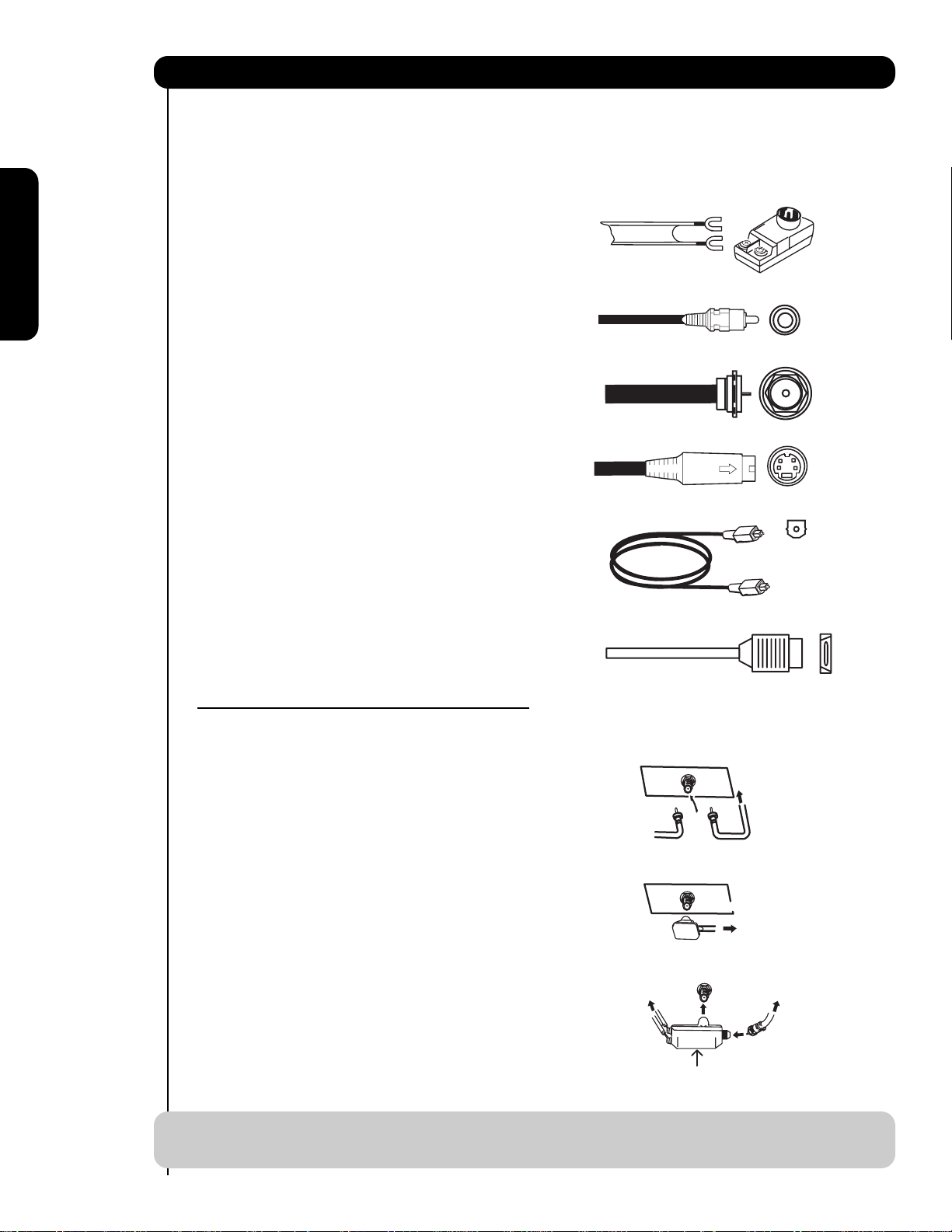
Hook-up Cables and Connectors
Cable
Cable
Most video/audio connections between components can be made with shielded video and audio cables that have
phono connectors. For best performance, video cables should use 75-Ohm coaxial shielded wire. Cables can be
purchased from most stores that sell audio/video products. Below are illustrations and names of common
connectors. Before purchasing any cables, be sure of the output and input connector types required by the
various components and the length of each cable.
300-Ohm Twin Lead
This outdoor antenna cable must be connected to an
antenna adapter (300-Ohm to 75-Ohm).
First time use
Phono
Cable
Used on all standard video and audio cables which
connect to inputs and outputs located on the
television’s rear jack panel and front control panel.
“F” Type 75-Ohm Coaxial Antenna
Cable
For connecting RF signals (antenna or cable TV) to the
antenna jack on the television.
S-Video (Super Video)
This connector is used on camcorders, VCRs and laserdisc players with an S-Video feature in place of the
standard video cable to produce a high quality picture.
Optical Cable
This cable is used to connect to an audio amplifier with
an Optical Audio In jack. Use this cable for the best
sound quality.
HDMI Cable
This cable is used to connect your external devices
such as Set-Top-Boxes or DVD players equipped with
an HDMI output connection to the TV’s HDMI input.
ANTENNA CONNECTIONS TO REAR JACK PANEL
VHF (75-Ohm) antenna/CATV (Cable TV)
When using a 75-Ohm coaxial cable system, connect
CATV coaxial cable to the AIR/CABLE (75-Ohm) terminal. Or
if you have an antenna, connect the coaxial cable to the
AIR / CABLE
To CATV cable
same AIR/CABLE terminal.
or
AIR / CABLE
To outdoor VHF
or UHF antenna
AIR / CABLE
VHF (300-Ohm) antenna/UHF antenna
When using a 300-Ohm twin lead from an outdoor
antenna, connect the VHF or UHF antenna leads to
screws of the VHF or UHF adapter. Plug the adapter
into the antenna terminal on the TV.
When both VHF and UHF antennas are
To outdoor antenna
To UHF
antenna
connected
Attach an optional antenna cable mixer to the TV
antenna terminal, and connect the cables to the
antenna mixer. Consult your dealer or service store for
the antenna mixer.
Antenna Mixer
NOTE: Connecting a 300-Ohm twin lead connector may cause interference. Using a 75-Ohm coaxial
cable is recommended.
6
6
To outdoor antenna
or CATV system
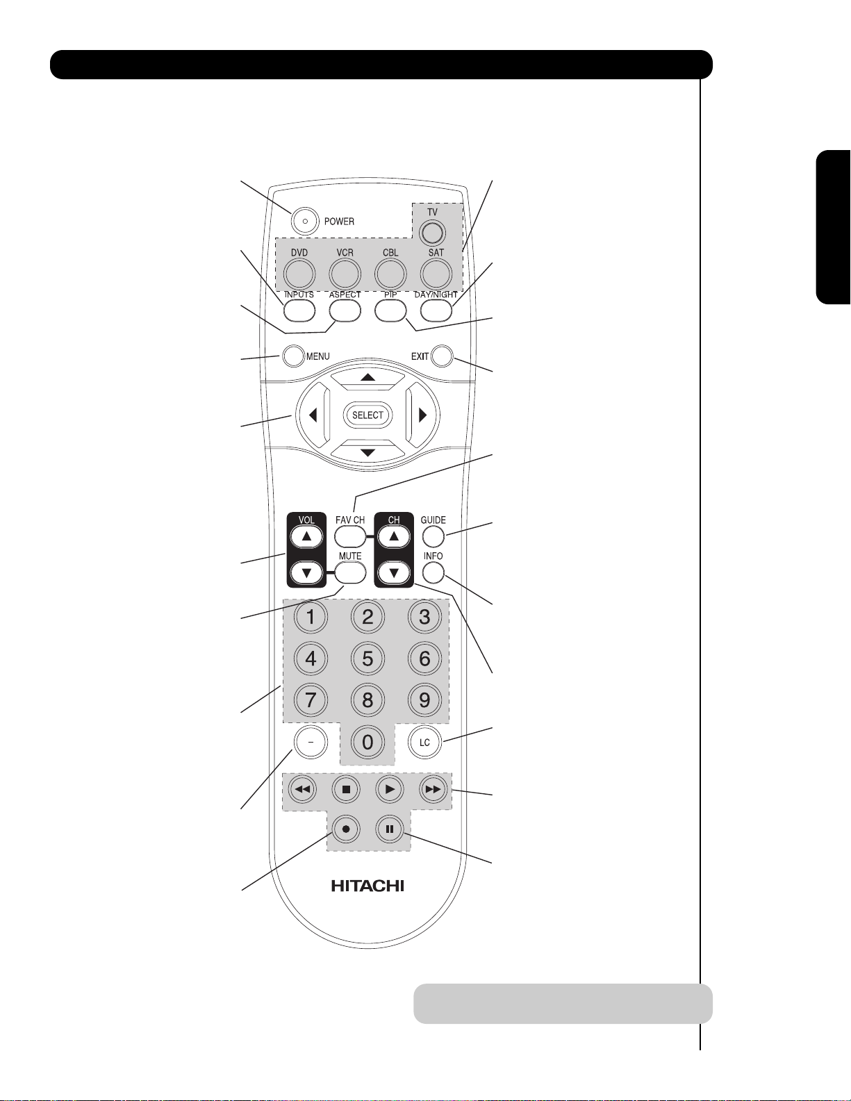
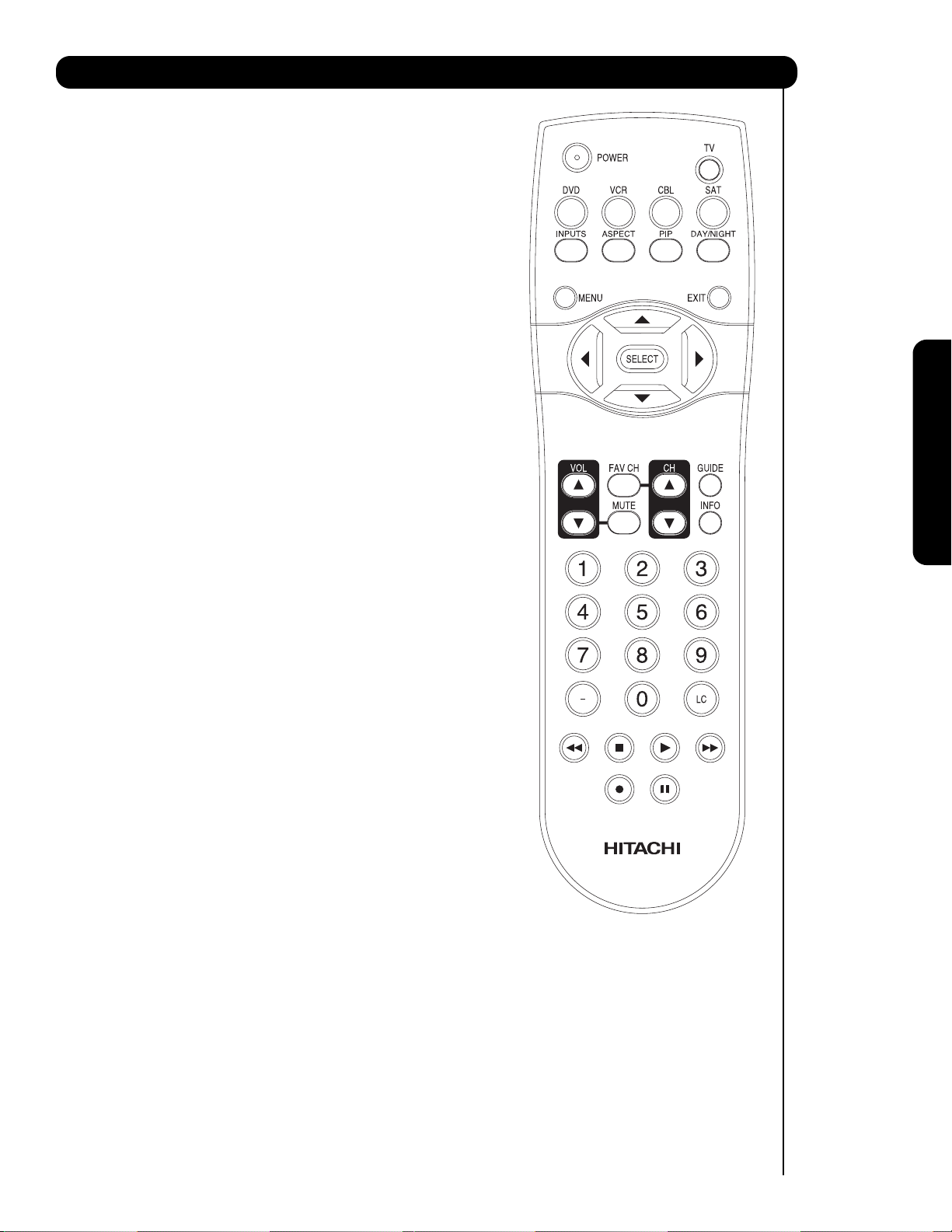
Quick Reference Remote Control Buttons and Functions
In addition to controlling all of the functions on your HITACHI LCD Rear Projection TV, the new remote control is
designed to operate different types of devices, such as, DVD Players, CBL (Cable Boxes), set-top-boxes, satellite
receivers, and VCRs. The remote control must be programmed to control the chosen device. Please see pages 1930 for a complete description of all features and programming of the Remote Control.
(TV, CBL, VCR, DVD, SAT)
POWER BUTTON
Turns the selected device on
and off.
INPUTS BUTTON (TV)
Accesses the INPUTS menu
system.
ASPECT BUTTON (TV)
Changes the aspect ratio while
watching TV.
MENU BUTTON
(CBL, DVD, SAT, TV)
Accesses the OSD menu
system.
CURSOR/SELECT BUTTONS
(TV, DVD, CBL, SAT)
The CURSOR buttons are used
to navigate the cursor through
the OSD and INPUTS menu
systems, and the SELECT
button is used to
Select/Activate the highlighted
menu item.
VOLUME BUTTONS (TV)
Adjusts the audio level of your
TV.
MUTE BUTTON (TV)
Reduces the audio level to 50%
if pressed once, and to
complete mute if pressed twice.
Press it a third time to restore
audio level.
NUMERIC BUTTONS
(TV, DVD, CBL, SAT, VCR)
Used to manually enter the TV
channel, and used for numeric
entry when navigating through
the OSD menu system.
(-) BUTTON (TV, SAT)
The (-) button is used when the
remote is in Set-Top-Box (STB)
mode or when the TV uses a
digital input.
RECORD BUTTON (VCR)
Press twice (2 times) to record
programs.
SOURCE ACCESS BUTTONS
(TV, DVD, VCR, CBL, SAT)
Changes the mode of the
Universal Remote Control to
control the device selected.
DAY/NIGHT BUTTON (TV)
Select picture mode settings
between DAY and NIGHT mode.
PIP BUTTON (TV)
Press to show and change the
Picture-in-Picture mode.
EXIT BUTTON
(TV, CBL, SAT)
Exits out of the OSD or INPUTS
menu systems if their menu is
displayed.
FAVORITE CHANNEL
(FAV CH) button (TV)
Press to enter/access Favorite
Channel (FAV) mode.
GUIDE BUTTON
(SAT, CBL)
Accesses the program guide of
other devices.
INFO BUTTON
(TV, CBL, SAT)
Displays various information on
the screen.
CHANNEL BUTTONS
(TV, CBL, SAT, VCR)
Changes the channel.
LAST CHANNEL (LC) BUTTON
(TV, CBL, SAT)
Switches between the current
and last channel viewed.
DVD/VCR CONTROL
BUTTONS (DVD, VCR)
Controls the precode functions
of your VCR and DVD.
PAUSE BUTTON
(TV, VCR, DVD)
Press to show and change the
Freeze mode of the TV or pause
other devices.
First time use
LEGEND
TV — Television VCR — Video Cassette Recorder/Player
CBL — Cable Box DVD — Digital Video Disc Player
SAT — Satellite Receiver
NOTE: STB precode is included in the
SAT mode.
7
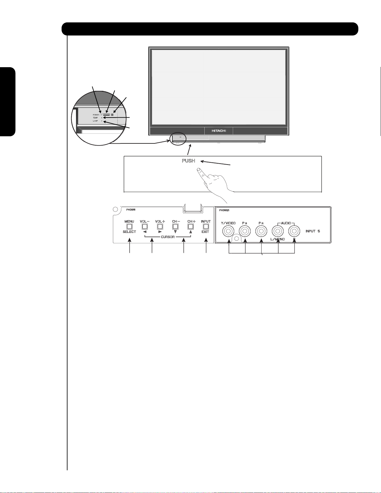
Front Panel Controls
First time use
햹
햶
햸
햺
햻
Front Control Panel Buttons & Connections
햲햳햵햴
Push to open the Front Control Panel Door
햷
쐃 MENU/SELECT button
This button allows you to enter the MENU, making it possible to set TV features to your preference without
using the remote. This button also serves as the SELECT button when in MENU mode.
쐇 INPUT/EXIT button
Press this button to display the input menu selections of CABLE/ AIR, INPUT: 1, 2, 3, 4 and 5. This button
also serves as the EXIT button when in MENU mode.
쐋 CHANNEL selector
Press these buttons until the desired channel appears in the top right corner of the TV screen. These buttons
also serve as the cursor down (
쐏 VOLUME level
Press these buttons for your desired sound level. The volume level will be displayed on the TV screen. These
buttons also serve as the cursor left (
turned OFF at a volume level 31 or greater, the volume level will default to 30 when the TV is turned ON.
However, if it is set to a level 30 or less, the volume level will be at the level it was set when the TV is turned
ON.
쐄 POWER button
Press this button to turn the TV ON or OFF.
쐂 FRONT INPUT JACKS (INPUT 5)
Use these audio/video jacks for a quick hook-up from a camcorder , VCR or a Y-P
view your favorite show , new recording or Video game. Press the INPUT button and select INPUT 5. If you have
mono sound insert the audio cable into the left audio jack.
) and up () buttons when in MENU mode.
) and right () buttons when in MENU mode. When the TV power is
BPR capability device to instantly
쐆 IR RECEIVER Sensor
Point the remote control at this area when selecting channels, adjusting volume, etc.
8
Front Panel Controls
쐊 POWER Light
When the TV is turned ON, the Power Light will first blink to indicate that the television lamp is warming
up. This light will be ON during normal operation. When the TV is turned OFF, the Power Light will blink
to indicate that the television lamp will be cooling down and the light will eventually turn off.
쐎 TEMP Indicator
This light is off during normal operation. If this indicator is lit, the optic unit is too hot. If this indicator is
blinking, the cooling fan has stopped. Please call service. The optic unit has an air filter that may become
clogged over time. The internal termperature will increse which will trigger the temperature sensor to display
an On-Screen warning. After 5 minutes, the lamp will turn off, then the TV will turn off with the TEMP LED On.
쐅 LAMP Indicator
This light is off during normal operation. If light is lit, the lamp has failed. See page 56-59 for lamp
replacement procedure. Consult your Hitachi dealer for proper part. If light is blinking, lamp cover is not
assembled securely after replacement.
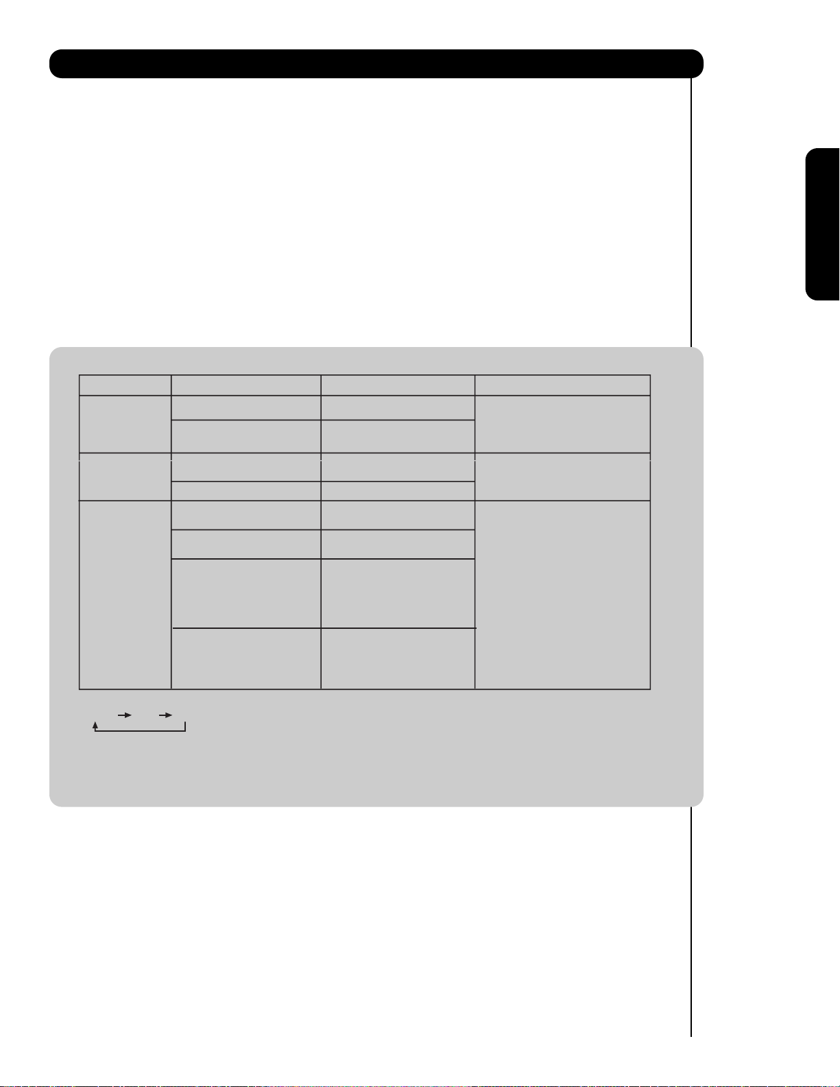
NOTES:
1.
INDICATOR INDICATION MEANING ACTION
LIGHT ON
LAMP LED
TEMP
LED
POWER
LED
2. If the LAMP, TEMP, and POWER LED are blinking in the order below, the television is warming up.
POWER TEMP LAMP
BLINKING
LIGHT ON
BLINKING
INTERMEDIATE BLINKING
(0.5 SEC CYCLE)
LIGHT ON
SHORT BLINKING
(0.3 SEC CYCLE)
LONG BLINKING
(1 SEC CYCLE)
NO LAMP LIGHT
or BROKEN LAMP
WRONG LAMP UNIT
ASSEMBLY / LAMP
DOOR OPEN
Too hot inside the
OPTICAL unit
COOLING FAN STOPPED
BEGINNING OF WARM UP
AFTER THE POWER ON.
NORMAL OPERATION
BEGINNING OF COOL DOWN
(FOR 20 SEC.)
(TV CANNOT ACCEPT ANY CODE
IN THIS PERIOD EXCEPT WITHIN
THE FIRST 5 SEC. OF COOLDOWN)
COOL DOWN
(FOR 6 MINUTES)
(TV CAN ACCEPT REMOTE
CONTROL AND FRONT BUTTONS)
Need to replace if
LAMP still does not light by
Power On ” again.
Check assembly condition of
LAMP UNIT
Call for Service
First time use
3. Your Hitachi LCD Rear Projection Television may appear to be OFF when it is set to input 1 ~ input 5 and the video
signal is not received from the input jacks. Please make sure the Blue Power light indicator is not lit (OFF) when
you are not watching for long lasting performance.
4. Your Hitachi LCD Rear Projection Television has an internal lamp that lights up the TV screen. Make sure to turn off
the Power when you do not watch the LCD Rear Projection Television for longer lamp life.
9
First time use
Video Camera
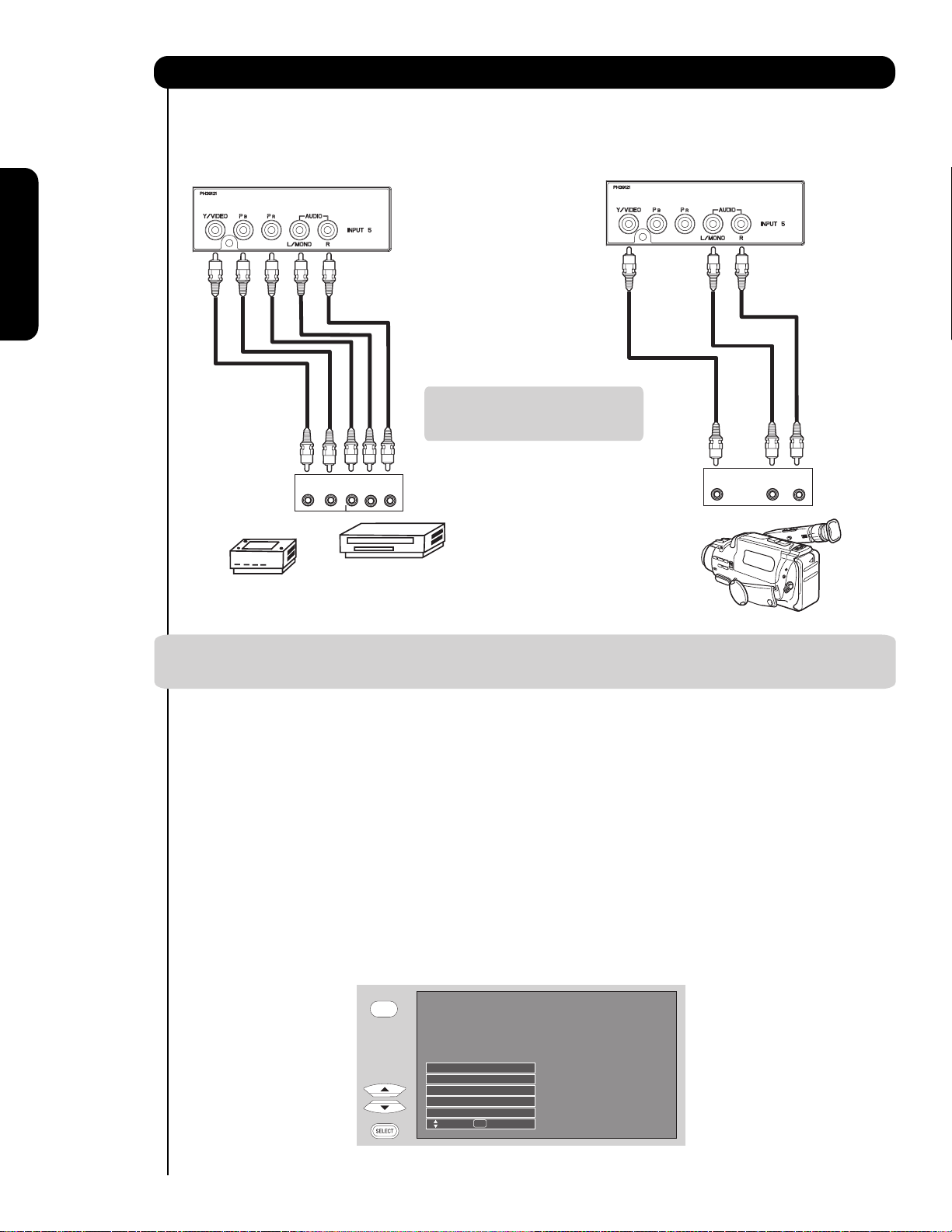
Jacks and ConnectionsFront Panel
The Front panel jacks are provided as a convenience to allow you to easily connect a camcorder , DVD, Video Game
as shown in the following examples :
Front Control Panel Connections
Note : Special device cables will be
required according to the
device specifications.
VIDEO
OUTPUT
L R
Video Game
OUTPUT
P
Y
L R
B/CBPR/CR
COMPONENT
OUTPUT CAPABILITY
DVD , Set Top Box,
Video Game Console.
NOTE: 1. Completely insert connection cord plugs when connecting to front panel jacks. If you do not, the
played back picture may be abnormal.
The exact arrangement you use to connect the VCR, camcorder, laserdisc player, DVD player, or HDTV Set
Top Box to your LCD TV is dependent on the model and features of each component. Check the
owner’s manual of each component for the location of video and audio inputs and outputs.
The following connection diagrams are offered as suggestions. However, you may need to modify them to
accommodate your particular assortment of components and features. For best performance, video and
audio cables should be made from coaxial shielded wire.
Before Operating External Video Source
Connect an external source to one of the INPUT terminals, then press the INPUTS button to show the
INPUTS menu. Use the CURSOR PAD ( and ) to select the Input of your choice. Then press
the SELECT button or the CURSOR PAD to confirm your choice (see page 22).
10
INPUTS
Input 4
Input 5
Cable
Air /
Input 1
Input 2
Move SEL Sel.
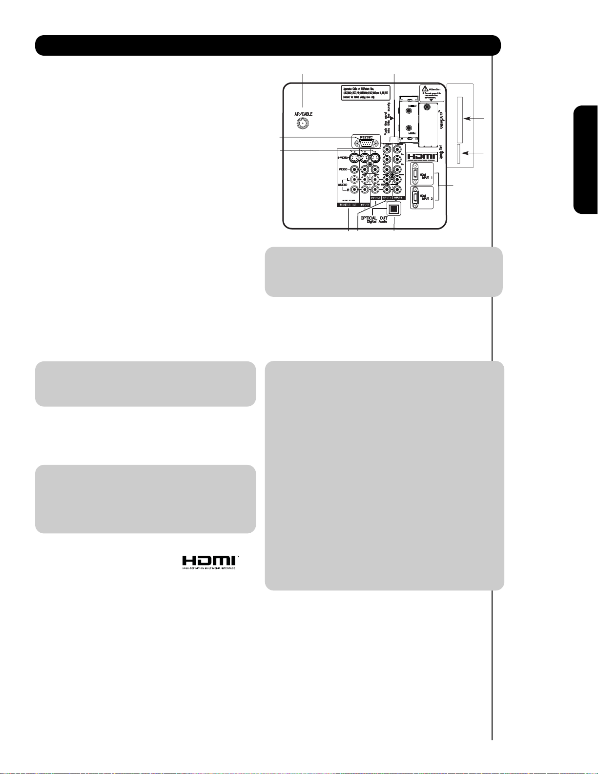
Rear Panel Connections
햲 Antenna Input
To switch between Cable and Air input, go to the
Channel Manager option to change the signal
source CABLE or AIR.
햳 Audio/Video INPUTS 1, 2, 3 and 4
By using the INPUTS button, the CURSOR PAD (
and ), and the SELECT button or CURSOR PAD
of the remote control, you can select each video
source. Use the audio and video inputs to connect
external devices, such as VCRs, camcorders,
laserdisc players, DVD players etc. (if you have
mono sound, insert the audio cable into the left
audio jack).
햴 MONITOR OUT & HI-FI AUDIO OUT
These jacks provide fixed and variable audio and
video signals (CABLE/AIR or INPUTS )
which are used for recording. Use the S-VIDEO
Output for high quality video output. Component
signal to INPUT 3, 4 and 5, and HDMI inputs will
not have monitor output.
햵 Optical Out (Digital Audio)
This jack provides Digital Audio Output for your
audio device that is Dolby
®
Digital and PCM
compatible, such as an audio amplifier.
햲
햺
햶
햴
햳
햸
햵
NOTE: 1. The HDMI input is not intended for use
with personal computers.
2. Only DTV formats such as 1080i, 720p, 480i
and 480p are available for HDMI input.
햸 Component: Y-P
INPUTS 3 and 4 provide Y-P
BPR Inputs
BPR jacks for
connecting equipment with this capability, such as
a DVD player or Set Top Box. You may use
composite video signal for both inputs.
햻
햹
햷
First time use
NOTE: *Manufactured under license from Dolby
Laboratories. “Dolby” and the double-D
symbol are trademarks of Dolby
Laboratories.
햶 S-VIDEO INPUTS 1 and 2
INPUTS 1 and 2 provide S-VIDEO (Super Video)
jacks for connecting equipment with S-VIDEO
output capability.
NOTE: 1. You may use HDMI, VIDEO or S-VIDEO
inputs to connect to INPUT 1 and 2, but only
one of these inputs may be used at a time.
2. S-VIDEO output may be used for
recording, only when the input is of SVIDEO type.
햷 HDMI INPUTS 1 and 2 (High Definition
Multimedia Interface)
ABOUT HDMI – HDMI is the
next-generation all digital interface for consumer
electronics. HDMI enables the secure distribution
of high-definition video and multi-channel audio in
a single cable. Because digital television (DTV)
signals remain in digital format, HDMI assures that
pristine high-definition images retain the highest
video quality from the source all the way to your
television screen.
Use the HDMI input for your external devices such
as Set-Top-Boxes or DVD players equipped with an
HDMI output connection.
NOTE: 1. Do not connect composite VIDEO and
S-VIDEO to INPUT 1, 2 at the same
time. S-VIDEO has priority over VIDEO input.
2. Your component outputs may be labeled
Y, B-Y, and R-Y. In this case, connect the
components B-Y output to the TV’s P
input and the components R-Y output to
the TV’s P
R input.
3. Your component outputs may be labeled
BCR. In this case, connect the component
Y-C
B output to the TV’s PB input and the
C
component C
R output to the TV’s PR input.
4. It may be necessary to adjust TINT to
obtain optimum picture quality when using
BPR inputs (see page 33).
the Y-P
5. To ensure no copyright infringement, the
MONITOR OUT output will be abnormal,
when using the Y-P
BPR jacks.
6. INPUT 3, 4 and INPUT 5 (Y/VIDEO) can be
used for composite video and component
video input.
햹
Upgrade Card
This card slot is for future software upgrades.
HITACHI will notify you if a software upgrade is
required for your TV. In order to receive written
notification, please complete and return your
warranty card.
햺 For AV control use Only
B
HDMI, the HDMI logo and High-Definition
Multimedia Interface are trademarks or registered
trademarks of HDMI Licensing LLC.
11
11
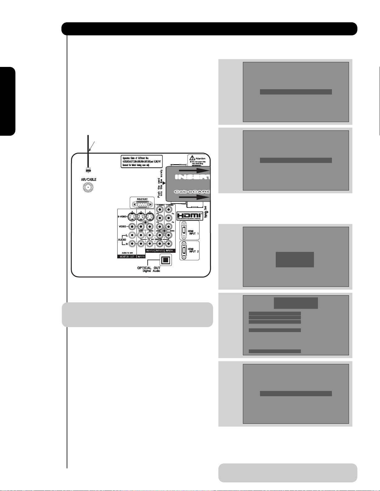
Rear Panel Connections
First time use
햻
CableCARD Slot
This slot is for the CableCARD that will be provided
by your local cable operator to gain access to
chosen cable channels. Please call your local cable
operator if this service is available before
requesting a CableCARD (also known as Point of
Deployment (POD) module).
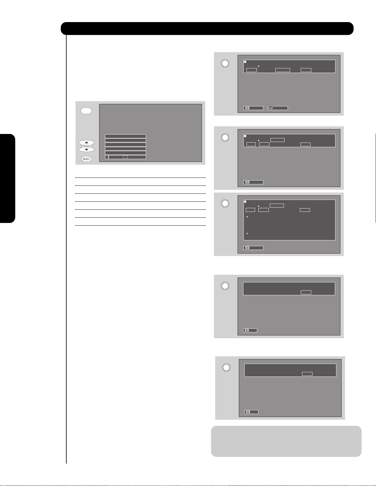
1. Connect a coaxial cable to cable terminal of
the Rear Panel Jacks.
2. Insert the CableCARD into the slot (Top of card
should be facing towards you as shown
below).
Digital Cable
INSERTINSERT
If the CableCARD is properly installed or removed, the
TV will display the following respective screens.
CableCARD is installed
OR
CableCARD is not installed
After the CableCARD is installed, wait until the second
screen below appears. The third screen below will
appear if a channel is not authorized for viewing. Press
the EXIT button to exit the second screen.
NOTE: 1. A digital cable subscription is required.
2. Do not insert a PCMCIA card into the
CableCARD slot.
Acquiring Data.
Please wait.
In order to start cable service
for this device, please contact
your cable provider
CableCARD(tm): 123-456-789-1
Host: 123-456-789-1
Data: 123-456-789-1
Unit Address: 123-456-789-1
Press EXIT to return
OR
Not an Authorized Channel
Please take note of all information on the screen (you
will provide this information to your cable operator).
Call your cable operator and give them the information
from the card to start your cable service.
1212
NOTE: Please make reference to CableCARD
information from SETUP menu (see page 54) .
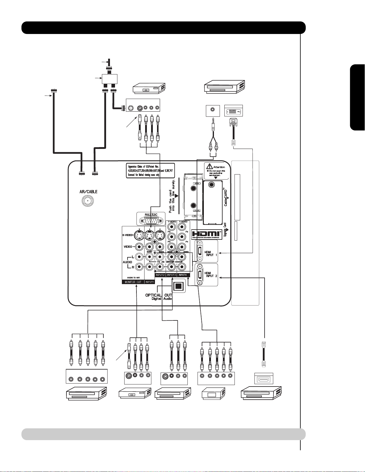
Rear Panel Connections
Cable TV coaxial cable
2-Way signal splitter
Outside
Antenna
ANT
IN
S-VIDEO
VCR #1
OUTPUT
VLR
DIGITAL
OUTPUT CAPABILITY
DIGITAL OUTPUT
AUDIO OUT
First time use
Optional
DVI
to
HDMI
Optional
OUTPUT
YP
L R
B/CBPR/CR
DVD Player
S-VIDEO
VCR #2
V L R
INPUT
NOTE: Cables are optional, except when specified.
V L R
S-VIDEO
OUTPUT
Laserdisc player, VCR,
camcorder, etc.
P
Y P
B
R
OUTPUT
HDTV Set-Top Box
L R
HDMI
to
HDMI
HDMI OUTPUT
HDMI DIGITAL
OUTPUT CAPABILITY
13

Tips on Rear Panel Connections
• S-VIDEO, Y-PBPR, or HDMI connections are provided for high performance laserdisc players, VCRs etc. that
have this feature. Use these connections in place of the standard video connection if your device has this
feature.
• If your device has only one audio output (mono sound), connect it to the left audio jack on (L/(MONO)) the
Rear Panel.
• Refer to the operating guide of your other electronic equipment for additional information on connecting
your hook-up cables.
• A single VCR can be used for VCR #1 and VCR #2, but note that a VCR cannot record its own video or line
output (INPUT: 1 in the example on page 14). Refer to your VCR operating guide for more information on
line input-output connections.
• Connect only 1 component (VCR, DVD player, camcorder, etc.) to each input jack.
• COMPONENT: Y-PBP
R
(Input 3, 4 & 5) connections are provided for high performance components, such as
DVD players and set-top-boxes. Use these connections in place of the standard video connection if your
device has this feature.
• Your component outputs may be labeled Y, B-Y, and R-Y. In this case, connect the components B-Y
output to the TV’s PBinput and the components R-Y output to the TV’s PRinput.
• Your component outputs may be labeled Y-CBCR. In this case, connect the components CBoutput to the
TV’s PBinput and the components CRoutput to the TV’s PRinput.
• It may be necessary to adjust TINT to obtain optimum picture quality when using the Y-PBPRinputs. (See
page 33)
• To ensure no copyright infringement, the MONITOR OUT output will be abnormal, when using the Y-PBPR, and
HDMI input jacks.
• Input 1 or 2 can accept HDMI signal.
• S-VIDEO monitor output may be used for recording only when the input is of S-VIDEO type.
• When using a HDMI input from a Set-Top-Box, it is recommended to use a 1080i or 720p input signal.
INSTALLATION RECOMMENDATION:
1. Video signals fed through a VCR may be affected by copyright protection systems and the picture will be
distorted on the television.
2. Connecting the television directly to the Audio /Video output of a Set-Top-Box will assure a more normal
picture.
First time use
14

Connecting External Video Sources
CONNECTING A VIDEO AND STEREO AUDIO
SOURCE TO INPUT1 – INPUT5
1. Connect the cable from the VIDEO OUT of the
VCR or the laserdisc player to the INPUT
(VIDEO) jack, as shown on the Rear Panel to the
right.
2. Connect the cable from the AUDIO OUT R of the
VCR or the laserdisc player to the INPUT
(AUDIO/R) jack.
3. Connect the cable from the AUDIO OUT L of the
VCR or the laserdisc player to the INPUT
(AUDIO/L) jack.
4. Press the INPUTS button, then select INPUT 2
from the INPUTS menu to view the program
from the VCR or laserdisc player.
5. Select CABLE or AIR from the INPUTS menu to
return to the last channel tuned.
CABLE
Air signal
or
First time use
Back of
VCR
OUTPUT
VCR
NOTE: 1. Completely insert the connection cord plugs when connecting to rear panel jacks. The picture and
sound that is played back will be abnormal if the connection is loose.
2. A single VCR can be used for VCR #1 and VCR #2 (see page 13) but note that a VCR cannot record
its own video or line output. Refer to your VCR operating guide for more information on line inputoutput connections.
3. When INPUT 3 , 4 or 5 are used, it is necessary to connect the video output of the device to the
Y/VIDEO input jack of the TV (For INPUT 5 please see page 10 for reference).
CONNECTING AN S-VIDEO AND STEREO AUDIO
SOURCE TO INPUT 1, 2
CABLE
or
Air signal
1. Connect the cable from the S-VIDEO OUT of
the S-VHS VCR or the laserdisc player to the
INPUT (S-VIDEO) jack, as shown on the Rear
Panel to the right.
2. Connect the cable from the AUDIO OUT R of
the VCR or the laserdisc player to the INPUT
(AUDIO/R) jack.
3. Connect the cable from the AUDIO OUT L of
the VCR or the laserdisc player to the INPUT
(AUDIO/L) jack.
4. Press the INPUTS button, then select INPUT 1
from the INPUTS menu to view the program
from the VCR or laserdisc player.
5. Select CABLE or AIR from the INPUTS menu to
return to the last channel tuned.
Back of VCR or
Laserdisc Player
R L V
S-VIDEO
OUTPUT
VCR or Laserdisc Player
NOTE: 1. Completely insert the connection cord plugs when connecting to rear panel jacks. The picture and
sound that is played back will be abnormal if the connection is loose.
2. A single VCR can be used for VCR #1 and VCR #2 (see page 13), but note that a VCR cannot record
its own video or line output. Refer to your VCR operating guide for more information on line inputoutput connections.
15
15
Connecting External Video Sources
First time use
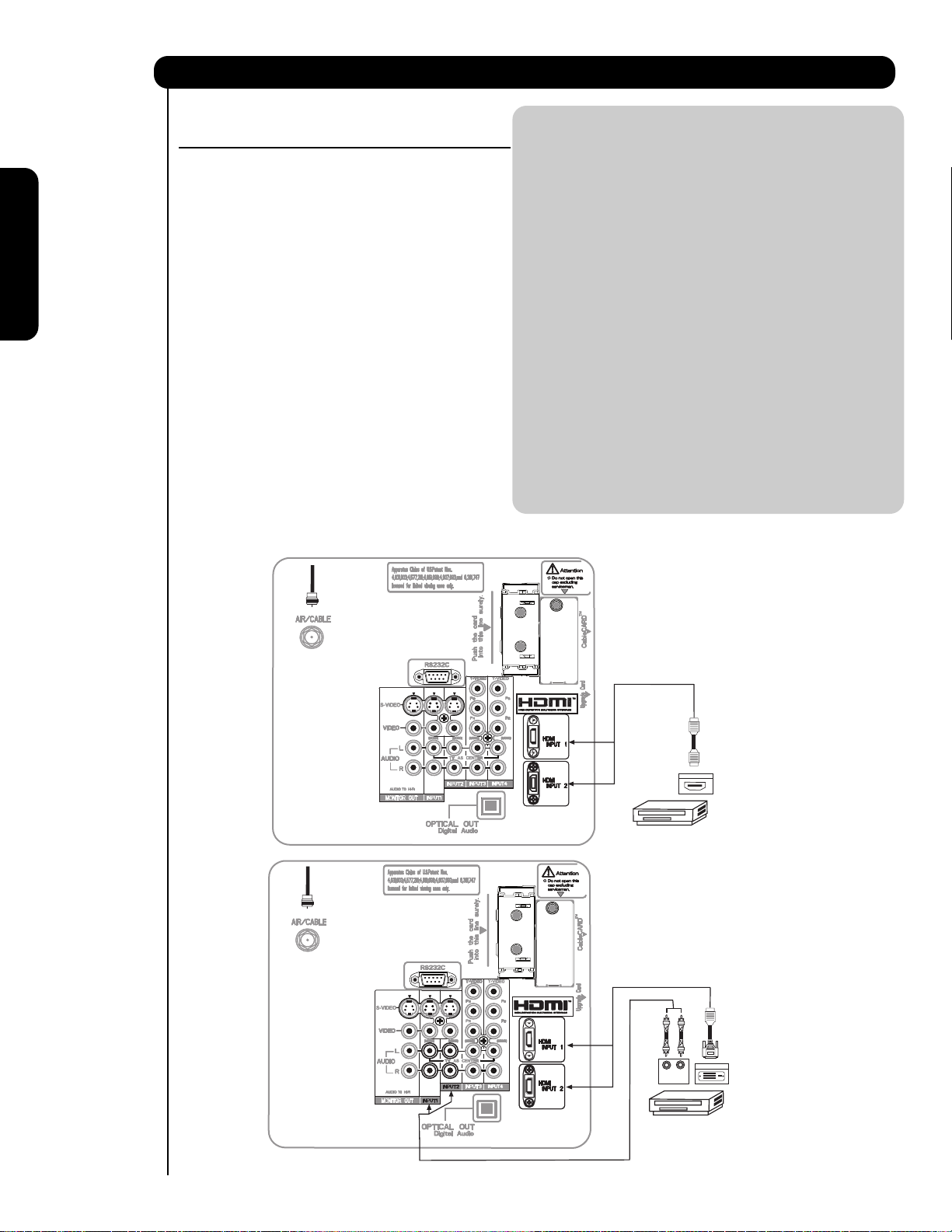
CONNECTING A COMPONENT SOURCE WITH
HDMI OR DVI CAPABILITY TO INPUT 1 OR 2
1. Connect the HDMI or DVI to HDMI connection
cable from the output of the HDTV set top box
or DVD player to the HDMI
input as shown on the Rear panel below.
2. With DVI output, connect the cable from the
AUDIO OUT R of the HDTV set top box or DVD
player to the INPUT (AUDIO/R) jack as shown on
the Rear Panel below.
3. With DVI output, connect the cable from the
AUDIO OUT L of the HDTV set top box or DVD
player to the INPUT (AUDIO/L) jack as shown
on the Rear Panel below.
4. Press the INPUTS button, then select INPUTS 1,
or 2 to view the program from the HDTV set
top box or DVD player.
5. Select CABLE or AIR from the INPUTS menu to
return to the last channel viewed.
HDMI input
CABLE
or
Air signal
NOTE: 1. Completely insert the connection cord
plugs when connecting to rear panel jacks.
The picture and sound that is played back
will be abnormal if the connection is loose.
2. The HDMI input on INPUT 1 and 2
contains the copy protection system called
High-bandwidth Digital Content Protection
(HDCP). HDCP is a cryptographic system
that encrypts video signals when using
HDMI connections to prevent illegal
copying of video contents.
3. HDMI is not a “NETWORK” technology. It
establishes a one-way point-to-point
connection for delivery of uncompressed
video to a display.
4. The connected digital output device
controls the HDMI interface so proper setup of device user settings determines final
video appearance.
5. When using a DVI to HDMI cable, connect
the Audio Out L and R cables at the same
INPUT (1 or 2) as your HDMI INPUT(1 or 2).
16
16
DVI to HDMI Input
CABLE
or
Air signal
HDMI
or
HDTV Set-Top-Box or
DVD Player
or
or
HDTV Set-Top-Box or
DVD Player
DIGITAL OUTPUT
P
R
LR
OUTPUT
P
B
DIGITAL OUTPUT
Cable
Back of
HDTV Set-Top-Box or
DVD Player
DVI to HDMI
Cable
Back of
HDTV Set-Top-Box or
DVD Player
Connecting External Audio/Video Devices
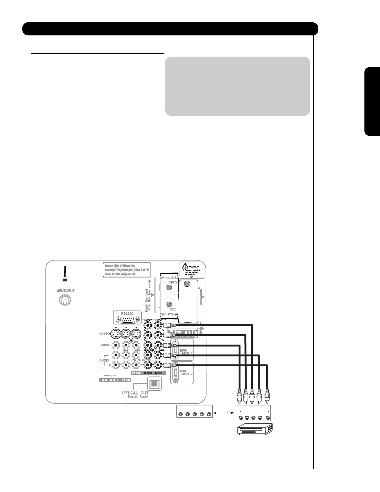
CONNECTING A COMPONENT AND STEREO
AUDIO SOURCE TO INPUT 3 , 4 or 5 :Y-P BPR.
1. Connect the cable from the Y OUT of the
Laserdisc/DVD player or HDTV set top box to
the INPUT (Y) jack, as shown on the Rear
panel below.
2. Connect the cable from the PB/CBOUT or BY OUT of the Laserdisc/DVD player or HDTV
set top box to the INPUT (PB)jack.
3. Connect the cable from the PR/CROUT or RY OUT of the Laserdisc/DVD player or HDTV
set top box to the INPUT (PR) jack.
4. Connect the cable from the AUDIO OUT R of
the Laserdisc/DVD player or HDTV set top box
to the INPUT (AUDIO/R) jack.
5. Connect the cable from the AUDIO OUT L of
the Laserdisc/DVD player or HDTV set top box
to the INPUT (AUDIO/L) jack.
6. Press the INPUTS button, then select INPUT 4
from the INPUTS menu to view the program
from the Laserdisc/DVD player or HDTV set
top box.
7. Select CABLE or AIR to return to the last
channel tuned.
NOTE: 1. Completely insert the connection cord
plugs when connecting to rear panel jacks.
The picture and sound that is played back
will be abnormal if the connection is loose.
2. See page 14 for tips on REAR PANEL
CONNECTIONS.
(For INPUT 5 please see page 10 for reference).
First time use
CABLE
or
Air signal
OUTPUT
LRYP
HDTV Set-Top Box
B P
AUDIO
L R
Back of
DVD Player
R
OR
OUTPUT
VIDEO
PR/CR PB/CBY
DVD Player
17
Connecting External Audio/Video Devices
First time use
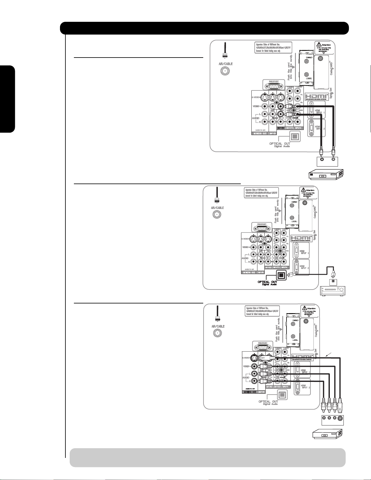
CONNECTING A VIDEO AND MONAURAL AUDIO
SOURCE TO INPUT 1 ~ INPUT 5
CABLE
Air signal
1. Connect the cable from the VIDEO OUT of the
VCR or the laserdisc player to the INPUT
(VIDEO) jack, as shown on the Rear Panel on the
right.
2. Connect the cable from the AUDIO OUT of the
VCR or the laserdisc player to the INPUT
(MONO)/L(AUDIO) jack.
3. Press the INPUTS button, then select INPUT 2
from the INPUTS menu to view the program
from the VCR or the laserdisc player.
4. Select CABLE or AIR from the INPUTS menu to
return to the previous channel.
(For INPUT 5 please see page 10 for reference).
CONNECTING OPTICAL OUT TO AN EXTERNAL AUDIO AMPLIFIER
CABLE
To connect the OPTICAL OUT of the TV to an
external audio amplifier, connect the system as
or
Air signal
shown on the right. The “OPTICAL OUT” from the
Rear Panel is a fixed output. The Volume of the
amplifier is controlled by the amplifier, not by the
LCD PTV. The OPTICAL OUT terminal outputs all
audio sources with Optical IN capability.
or
Back of
AUDIO OUT VIDEO OUT
VCR
OUTPUT
VCR
1. Connect an optical cable from the Optical out to
the Optical input of a separate Stereo System
Amplifier as shown on the Rear Panel on the
right.
CONNECTING MONITOR OUT
CABLE
The MONITOR OUT terminal outputs video and
or
Air signal
audio of CABLE/AIR and INPUTS 1, 2, 3, 4 and 5. It
does not output component and HDMI video.
1. Connecting S-Video:
Connect the cable from the S-VIDEO OUT of
the Rear Panel to the INPUT (S-VIDEO) jack, of
the VCR .
Connecting Video:
Connect the cable from the VIDEO INPUT of
the VCR to the VIDEO out jack on the
TV Rear Panel.
2. Connect the cable from the AUDIO IN R of the
VCR to the OUTPUT (AUDIO/R) jack on the
TV Rear Panel.
3. Connect the cable from the AUDIO IN L of the
VCR the OUTPUT (AUDIO/L) jack on the
TV Rear Panel.
NOTE: When making video connections, connect S-Video only or Video only. If both are connected, S-
18
Video takes priority.
Stereo System Amplifier
OPTICAL
IN
Stereo System Amplifier
or DVD Player
Optional
R L V
INPUT
VCR or other external
components
S-VIDEO
The Remote Control
In addition to controlling all the functions on your
HITACHI LCD rear projection Television , the new remote
control is designed to operate different types of VCRs,
CATV (Cable TV) converters, set-top-boxes, satellite
receivers (SAT) and DVD players with one touch. Basic
operation keys are grouped together in one area.
To operate your TV, point the remote control at the
screen of the TV and press the TV button. The remote
will now control your television.
To operate your VCR, point the remote at the remote
sensor of the VCR and press the VCR button. The
remote will now control your VCR (see page 30 for
instructions on how to program the remote to control
your VCR).
To operate your cable box, point the remote at the
remote sensor of the cable box and press the CABLE
(CBL) button. The remote will now control your cable
box (see page 27 for instructions on how to program
the remote to control your cable box).
To operate your set-top-box or satellite receiver, point
the remote at the remote sensor of the set-top-box or
satellite receiver and press the SAT button. The remote
will now control your set-top-box or satellite receiver. If
you have a satellite receiver, use this button to program
your satellite receiver (see page 28 for instructions on
how to program the remote to control your SAT).
The Remote Control
To operate your DVD player, point the remote at the
remote sensor of the DVD player and press the DVD
button. The remote will now control your DVD player
(see page 29 for instruction on how to program the
remote to control your DVD player).
19

How to Use the Remote to Control Your TV
쐃 POWER button
Press this button to turn the TV set on or off when
the remote is in TV mode.
쐇 MODE buttons
These buttons allow the remote to control your TV,
VCR, DVD, Cable box/Satellite box depending on
which button is pressed. Refer to page 31~34 for
how to change between each of these modes.
쐋 PAUSE button
Press the PAUSE button to freeze the picture.
Press the EXIT button to return the picture to
motion. Press the PAUSE button repeatedly to
cycle through the three different freeze modes (see
page 26).
쐏 DAY/NIGHT button
Press this button to toggle between Day and Night
picture mode settings. Select DAY for day time
viewing with more brightness and contrast to
compete with room light. Select NIGHT for night
time viewing with less brightness and contrast for a
more detailed picture (see page 33 for settings
changes).
쐃
쐇
쐂
쐄
쐊
쐏
쐆
쐅
쐈
씉
The Remote Control
씈
씊
씌
쐎
쐉
씉
씋
쐋
EXIT
Freeze
Freeze
Freeze
Freeze
Freeze
20

How to Use the Remote to Control Your TV
쐄
ASPECT button
Press this button to quickly change the picture format ASPECT ratio. Depending on the input signal format
received, the picture format ratio allows you to adjust the images through the following options.
4:3 STANDARD
Use this aspect mode to display conventional (4:3)
images. Side panels (gray areas) are placed to the
left and right of the image to preserve the original
aspect ratio of the source. Note: Use this mode for
only 15% of your total viewing time to prevent
uneven aging of the phosphors. Phosphors in the
lighted area of the picture will age more rapidly
than the gray areas.
4:3 EXPANDED
Use this aspect mode to display conventional (4:3)
sources by linearly increasing image expansion
from the center towards the edges of the display
area in order to fill it.
• Antenna-Analog Channel
• S-Video/Video Input
(Auto Aspect: Off)
• HDMI-480i/480p Input
(Auto Aspect: Off)
• Component-480i/480p
Input (Auto Aspect: Off)
Note: Please see Appendix A
on page 74.
IMA GE INPUT
4:3 ZOOM1/ZOOM2
Use these aspect modes to zoom in on
conventional (4:3) sources.
16:9 STANDARD
Use this aspect mode to display 16:9 sources like
HDTV and DVD’s preserving the original 16:9
aspect ratio.
16:9 ZOOM
Use this aspect to Zoom-in once while in 16:9
aspect.
The Remote Control
• Antenna-Digital Channel (4:3)
• S-Video/Video 4:3/Letter
Input (Auto Aspect: On)
• HDMI-480i/480p 4:3/
Letter Input (Auto Aspect: On)
• Component-480i/480p 4:3/
Letter Input
(Auto Aspect: On)
Note: Please see Appendix A
on page 74.
• S-Video/Video 16:9 Input
(Auto Aspect: On)
• HDMI-480i/480p 16:9 Input
(Auto Aspect: On)
• Component-480i/480p
16:9 Input
(Auto Aspect: On)
Note: Please see Appendix A
on page 74.
• Antenna-Digital Channel (16:9)
• HDMI-720p/1080i Input
• Component-720p/1080i
Input
IMA GE INPUT
IMA GE INPUT
IMA GE INPUT
Note: Please see Appendix A
on page 74.
NOTE: 1. The Aspect Style in all five video inputs have independent Aspect Style setting.
2. Vertical position adjustments are directly available when you choose 4:3
EXPANDED/ZOOM1/ZOOM2 or 16:9 ZOOM aspect style (see also page 34).
21
How to Use the Remote to Control Your TV
CABLE
The Remote Control
쐂 INPUTS button
When the remote control is in TV mode, press this
button to access the INPUTS menu. Use the
CURSOR and SELECT buttons to scroll and select
the inputs that are being used. Pressing the
INPUTS button repeatedly will also cycle through
the Inputs menu items. Then press the SELECT
button to select.
INPUTS
Input 4
Input 5
Air /
Cable
Input 1
Input 2
Move SEL Select
INPUT 1 Select to choose INPUT 1.
INPUT 2 Select to choose INPUT 2.
INPUT 3 Select to choose INPUT 3.
INPUT 4 Select to choose INPUT 4.
INPUT 5 Select to choose INPUT 5.
AIR/ Select between Air or Cable signal.
INFO button display for Analog Channels
INFO
Show Name Air 8
3:00PM-
3:30PM KXYZ-HD
ST TV-G 480i 3:17PM
Auto STEREO
INFO button display for Digital Channels
INFO
INFO
Show Name Cable 8 -1
3:00PM-
Engl 1080i 3:17PM
Auto
Show Name
3:00PM-
Engl 1080i 3:17PM
The show description will be in this area of the screen.
ALT U.S.
3:30PM KXYZ-HD
DTVCC
ALT U.S.
3:30PM KXYZ-HD
DTVCC
Cable 8 -1
쐆 PICTURE-IN-PICTURE button
See separate section on pages 24-25 for a
description.
쐊 MENU button
The MENU button will start the On-Screen Display.
쐎 GUIDE button
[Cable Box (CBL), Satellite Receiver (SAT)
modes only]
The use of this button is only applicable when the
remote control is in (CBL) and (SAT/STB) mode.
Press this button to access the Channel Guide of
the (CBL), and (SAT/STB).
쐅 EXIT button
This button will exit all On-Screen Displays.
쐈 CURSOR buttons/SELECT button
All the On-Screen Display features can be set or
adjusted by using the CURSOR buttons and the
SELECT button, except for numeric entries. Press
the CURSOR buttons toward desired direction and
press the SELECT button to select.
쐉 INFO button
Press this button when you want to check the
channel being received, the picture source, if the
channel has stereo (ST) or second audio program
(SA), the time, CHANNEL ID and if the TIMER is set.
Auto
INFO button display when an S-VIDEO Input is
connected to INPUT 1
INFO
Auto
S-IN: 1
480i 3:17PM
INFO button display for when a COMPONENT
VIDEO: Y-P
INFO
BPR Input is connected to INPUT 3
Y-PBPR: 3
480i 3:17PM
Auto
NOTE: 1. Press the INFO button again or the EXIT
button to return to normal viewing.
2. The Aspect setting will not be shown if
the channel is locked.
22
How to Use the Remote to Control Your TV
씈 VOLUME (VOL), MUTE button
Press the VOLUME button (
or ) until you
obtain the desired sound level.
To reduce the sound to one half of normal volume
(SOFT MUTE) to answer the telephone, etc., press
the MUTE button. Press the MUTE button again to
turn the sound off completely (MUTE). To restore
the sound, press the MUTE button one more time,
or VOL UP (
MUTE
).
Volume 8
Press the FAV CH button to switch to Favorite
(FAV) channel mode. You will know you are in
Favorite Channel mode when (FAV) is displayed
and the displayed channel is GREEN. Press it
again to return to your regular tuned channels. You
can add any channel to your Favorite channel list
by pressing and holding down the FAV CH button
until the displayed channel turns from WHITE to
highlighted GREEN. You can also delete a channel
from your favorite channel list by pressing and
holding down the FAV CH button until the
displayed channel turns highlighted GREEN to
WHITE.
Cable 6
FAV CH
FAV Cable 6
First time use
The Remote Control
Soft Mute 8
MUTE
Mute 8
Closed Captioning will display automatically when
MUTE/SOFT MUTE is on and Closed Caption is set
to AUTO (see page 52).
When the TV power is turned off at a volume level
31 or greater, the volume level will default to 30
when the TV is turned on. However, if it is set to a
level 30 or less, the volume level will be at the level
it was set when the TV is turned on.
씉 CHANNEL SELECTOR/FAVORITE CHANNEL
(FAV CH) buttons
The CHANNEL SELECTOR buttons are used to
select channels, lock access code, etc. Use the
CHANNEL SELECTOR buttons to enter one, two,
or three numbers to select channels. Enter 0 first
for channels 1 to 9, or simply press the single digit
channel you wish to tune then wait a few seconds
for the TV to tune. Channel selection may also be
performed by CHANNEL (CH) UP (
CHANNEL (CH) DOWN (
).
) or
FAV CH
Cable 6
씊 (-) DASH button
The (-) DASH button can only be used when the
remote control is in Satellite (SAT) mode.
씋 LAST CHANNEL (LC) button
Press this button to toggle between the current and
last channel viewed.
씌 RECORD button
Press twice (two times) to record programs when
the remote is in VCR mode.
23

The Remote Control
Picture-in-Picture (PIP)
Your HITACHI LCD TV incorporates one Tuner
technology designed for improved viewing enjoyment.
This feature allows you to view Digital Channels and
Video inputs on both the main picture and sub picture
simultaneously, with separate control.
When a Digital channel is viewed in the main picture,
the Digital or Analog channel can not be viewed in
the sub picture. Please see table for PIP availability.
To select between main picture and PIP sub picture,
use the CURSOR PAD button the remote. The Green
highlighted channel display will move with every press
of the CURSOR PAD buttons.
The Picture-in-Picture feature is convenient when you
want to watch more than one program at the same
time. You can watch a TV program while viewing other
programs from any of the video inputs.
Use connection at right to view VCR program as a subpicture while viewing another program as main picture
(CABLE/AIR Digital channel).
햲 PIP button
Press the PIP button and a sub-picture will appear
in one of the four different modes (POP, PIP, or
SPLIT), depending on the INPUT signal. To change
the PIP mode, use the PIP button to cycle through
the three different modes.
CABLE
or
Air signal
Back of
VCR
AUDIO OUT VIDEO OUT
OUTPUT
VCR
SPLIT MODE PICTURE-IN-PICTURE
Split Mode PIP displays the main picture and sub-
picture evenly on the screen.
SWAP
Main Picture
Sub Picture
POP MODE PICTURE-IN-PICTURE
POP Mode PIP displays the sub-picture outside of
the main picture. Use the CURSOR PAD ( or )
to move the sub-picture. This feature is not
available with a 1080i/720p signal. Please refer to the
PICTURE-IN-PICTURE MODES Table (see page
25).
Main Picture
Sub Picture
SWAP
쐃
쐇
NOTE : 1. Press the CURSOR PAD ( or ) to
enable the sub-picture sound.
24

Picture-In-Picture (PIP)
PIP MODE PICTURE-IN-PICTURE
Select CABLE/AIR or INPUT 1~5 from the INPUTS menu. Select a channel that has a 1080i/720p signal.
To prevent a pattern burn, occasionally move the sub-picture using the CURSOR PAD.
Main Picture
PIP Specifications Table
PIP
Scan
Mode
Mode
PO P 1080i
PIP
4x3
PIP
16x9
SPLIT 1080i
STROBE 1080i
Yes : Available
( - ) : Not available
Main
540p
1080i/720p 16x9 - - - - - - -
S -Video/V ideo 16x9/4x3
1080i
540p
1080i/720p 16x9 - YE S - - - - -
S -Video/V ideo 16x9/4x3
1080i
540p
1080i/720p 16x9 YE S - - - - - -
S -Video/V ideo 16x9/4x3
540p
S -Video/V ideo 16x9/4x3 YE S Y ES - - - - -
540p
S -Video/V ideo 16x9/4x3 - - - - - - YE S
SWAP
Sub
Aspect
16x9 - - - - - - -ANT Digital
4x3 - - YES YES YES YES YES
480p/480i 16x9/4x3
16x9 - - - - YE S YES YESANT Digital
4x3-------
480p/480i 16x9/4x3
16x9 - - YES YES YES YES YESANT Digital
4x3-------
480p/480i 16x9/4x3
16x9 - - YES YES YES YES YESANT Digital
1080i 16x9 YE S YE S - - - - -
720p 16x9 YE S Y ES - - - - 480p 16x9/4x3 YE S Y E S - - - - -
480i 16x9/4x3 YE S Y ES - - - - -
1080i 16x9 - - YE S - - - -
720p 16x9 - - - Y ES - - 480p 16x9/4x3 - - - - YE S - -
480i 16x9/4x3 - - - - - Y ES -
4x3 - - YES YES YES YES YES
16x9 Y ES - - - - - -ANT Digital
4x3-YES-----
Digital Tuner 1080i 720p 480p Video/S-Video
16x9 4x3 16x9 16x9 16x9/4x3 16x9 4x3
YESYES-----
-------
-------
Sub Picture
480i
The Remote Control
25

Picture-In-Picture (PIP)
The Remote Control
햳 PAUSE button
If you wish to freeze the sub-picture, press the
PAUSE button. This is convenient when trying to
write down the address for a mail order company,
recording statistics for a sporting event, etc. To
return the picture to motion, press the EXIT
button. Press the PAUSE button repeatedly to
toggle between FREEZE modes (Main Freeze,
SPLIT and STROBE).
Freeze
Freeze
Freeze
Freeze
Freeze
SPLIT FREEZE
Press the PAUSE button to freeze the picture you
are currently viewing (only the right sub-picture will
freeze). Press the EXIT button to return to normal
viewing.
Main Picture
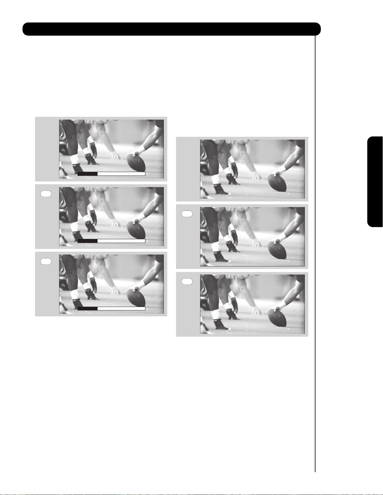
STROBE FREEZE
Press the PAUSE button to freeze three frames of
the picture you are currently viewing (only the 3
sub-pictures will freeze). Press the EXIT button to
return to normal viewing. This feature is useful for
viewing a moving picture that has many details, for
example, a close play in a sporting event or a golf
swing.
Sub Picture
MAIN FREEZE
Press the PAUSE button to freeze one frame of the
picture you are currently viewing and the frozen
frame will show in the Main Picture. Press the EXIT
button to return to normal viewing. This feature is
useful for freezing a picture frame with addresses.
Hot Springs Clay Mask
C/O John Doe
Run-Spa Retreat
P.O. Box 55512
Any Town, USA 98765
Check or
Money Order Only
1-800-555-1212
NOTE: 1. The default FREEZE mode is the MAIN
freeze followed by the SPLIT freeze and
then the STROBE freeze. The last FREEZE
mode you selected before you pressed the
EXIT button will be the one that comes up
after pressing the PAUSE button again.
2. Each freeze frame in Strobe Freeze is
delayed about 0.1 (1/10) second.
26

The Remote Control for Cable Box Functions
OPERATING THE PRECODED
FUNCTION FOR YOUR CABLE BOX.
This remote is designed to operate different types of
cable boxes. You must first program the remote to
match the remote system of your cable box (refer
below for pre-codes).
1. Turn ON your cable box.
쐇
쐋
쐃
2. Aim the remote control at the front of your cable
box.
3. To switch to Cable (CBL) pre-coded mode, press
and release the CABLE (CBL) button.
4. Hold down the CBL button on the remote and
enter the two digit preset code that matches your
cable box, as shown below. Release the CBL
button.
5. Aim the remote at the cable box and press the
POWER button. The remote will turn off your cable
box when the correct two digit preset code is
entered. When this occurs, the remote control is
programmed for your cable box. If the cable box
does not turn off, try a different two digit preset
code.
6. The remote will now control your Cable box.
NOTE: 1. If your cable box cannot be operated after
performing the above procedures, your
cable box code has not been precoded
into the remote.
2. In the unlikely event that your cable box
cannot be operated after performing the
above procedures, please consult your
cable box operating guide.
3. The remote control will remember the
codes you have programmed until the
batteries are removed from the remote
control. After replacing the batteries
repeat the entire programming procedure
as stated above.
쐃 CABLE (CBL) button
This button allows the remote to control your cable
box by setting it to CABLE mode.
쐇 PRECODED CABLE BOX buttons
These buttons transmit the chosen precoded cable
codes.
쐋 EXCLUSIVE TV buttons
These buttons are for operating the TV.
쐇
The Remote Control
쐋
쐇
CABLE BRAND Analog Type CODES
HAMLIN......................................................22, 23, 24, 25
JERROLD .................... 00, 01, 02, 03, 04, 05, 06, 07,21
OAK..................................................................26, 27, 28
PANASONIC.................................................... 18, 19, 20
PIONEER ................................................................13, 14
SCIENTIFIC ATLANTA......................................08, 09, 10
TOCOM ..................................................................15, 16
ZENITH...................................................................11, 12
G.I. ..............................................................................17
CABLE BRAND DIGITAL TYPE CODES
PIONEER..............................................................29
SCIENTIFIC ATLANTA ..................................................................30
MY CABLE BOX CODE IS: _______________________
NOTE: Refer to instruction manual of the Cable Box
for operation of the buttons exclusively for
the Cable Box.
27

The Remote Control for Set-Top Box/Satelite Receiver Functions
OPERATING THE PRECODED FUNCTION FOR
YOUR SET-TOP-BOX/SATELLITE RECEIVER.
This remote is designed to operate different types of
set-top-box/satellite systems. You must first program
the remote to match the remote system of your settop-box/satellite systems (refer below for pre-codes).
1. Turn ON your set-top-box/satellite systems.
쐇
쐃
쐋
The Remote Control
2. Aim the remote control at the front of your set-topbox/satellite systems.
3. To switch to set-top-box/satellite (STB) pre-coded
mode, press and release the SAT button.
4. Hold down the SAT button on the remote and enter
the two digit preset code that matches your settop-box/satellite receiver, as shown below. Release
the SAT button.
5. Aim the remote at the set-top-box/satellite receiver
and press the POWER button. The remote will turn
off your set-top-box/satellite receiver when the
correct two digit preset code is entered. When this
occurs, the remote control is programmed for your
set-top-box/satellite receiver. If the set-topbox/satellite receiver does not turn off, try a
different two digit preset code.
6. The remote will now control your set-topbox/satellite receiver.
NOTE: 1. If your set-top-box/satellite receiver
cannot be operated after performing the
above procedures, your set-topbox/satellite receiver code has not been
precoded into the remote.
2. In the unlikely event that your set-topbox/satellite receiver cannot be operated
after performing the above procedures,
please consult your set-top-box/satellite
receiver operating guide.
3. The remote control will remember the
codes you have programmed until the
batteries are removed from the remote
control. After replacing the batteries
repeat the entire programming procedure
as stated above.
쐇
쐋
쐇
SATELLITE BRAND CODES
ECOSTAR .....................................................................03
HITACHI....................................................................... 00
HUGHES ......................................................................04
RCA ..............................................................................01
SONY ...........................................................................02
쐃 SAT (Set-Top-Box/Satellite) button
This button allows the remote to control your settop-box/satellite receiver by setting it to SET-TOPBOX/SATELLITE mode.
쐇 PRE-CODED SET-TOP-BOX/SATELLITE
RECEIVER buttons
These buttons transmit the chosen pre-coded settop-box/satellite codes.
쐋 EXCLUSIVE TV buttons
These buttons are for operating the TV.
28
SET TOP BOX BRAND CODES
PANASONIC.................................................................05
RCA ............................................................................. 06
SAMSUNG ...................................................................07
ZENITH.........................................................................08
MY SATELLITE RECEIVER/
SET TOP BOX CODE IS: _________________________
NOTE: Refer to instruction manual of the set-top-
box/satellite receiver for operation of the
buttons exclusively for the set-topbox/satellite receiver.

The Remote Control for DVD Functions
OPERATING THE PRECODED
FUNCTION FOR YOUR DVD PLAYER.
This remote is designed to operate different types of
DVD players. You must first program the remote to
match the remote system of your DVD player (refer
below for pre-codes).
1. Turn ON your DVD player.
쐇
쐃
쐋
2. Aim the remote control at the front of your DVD
player.
3. To switch to DVD pre-coded mode, press and
release the DVD button.
4. Hold down the DVD button on the remote and
enter the two digit preset code that matches your
DVD player, as shown below. Release the DVD
button.
5. Aim the remote at the DVD player and press the
POWER button. The remote will turn off your DVD
player when the correct two digit preset code is
entered. When this occurs, the remote control is
programmed for your DVD player. If the DVD player
does not turn off, try a different two digit preset
code.
6. The remote will now control your DVD player.
7. You will need to set the display type of your DVD
player to 16:9 WIDESCREEN.
NOTE: 1. If your DVD player cannot be operated
after performing the above procedures,
your DVD player’s code has not been
precoded into the remote.
2. In the unlikely event that your DVD player
cannot be operated after performing the
above procedures, please consult your
DVD player operating guide.
3. The remote control will remember the
codes you have programmed until the
batteries are removed from the remote
control. After replacing the batteries
repeat the entire programming procedure
as stated above.
쐃 DVD button
This button allows the remote to control your DVD
player by setting it to DVD mode.
쐇 PRECODED DVD Buttons
These buttons transmit the chosen precoded DVD
codes.
쐋 EXCLUSIVE TV Buttons
These buttons are for operating the TV.
쐇
The Remote Control
쐋
쐇
쐇
DVD BRAND CODES
APEX ............................................................................10
GO VIDEO ................................................................... 09
HITACHI........................................................................00
KENWOOD ...................................................................11
PANASONIC.................................................................02
PIONEER ..................................................................... 03
RCA ............................................................................. 04
SAMSUNG ...................................................................06
SANYO .........................................................................07
SONY ...........................................................................01
TOSHIBA ......................................................................05
MY DVD PLAYER CODE IS: ______________________
NOTE: Refer to instruction manual of the DVD player
for operation of the buttons exclusively for
the DVD player.
29

OPERATING THE PRECODED
FUNCTION FOR YOUR VCR.
This remote is designed to operate different types of
VCRs. You must first program the remote to match the
remote system of your VCR (refer below for pre-codes).
1. Turn ON your VCR.
2. Aim the remote control at the front of your VCR.
3. To switch to VCR pre-coded mode, press and
release the VCR button.
4. Hold down the VCR button on the remote and
enter the two digit preset code that matches your
VCR, as shown below. Release the VCR button.
5. Aim the remote at the VCR and press the POWER
button. The remote will turn off your VCR when the
correct two digit preset code is entered. When this
occurs, the remote control is programmed for your
VCR. If the VCR does not turn off, try a different
two digit preset code.
6. The remote will now control your VCR.
NOTE: 1. If your VCR cannot be operated after
performing the above procedures, your
VCR’s code has not been precoded into
the remote.
2. In the unlikely event that your VCR cannot
be operated after performing the above
procedures, please consult your VCR
operating guide.
3. The remote control will remember the
codes you have programmed until the
batteries are removed from the remote
control. After replacing the batteries
repeat the entire programming procedure
as stated above.
4. Press the Record button twice to record.
쐃 VCR button
This button allows the remote to control your VCR
player by setting it to VCR mode.
쐇 PRECODED VCR Buttons
These buttons transmit the chosen precoded VCR
codes.
쐋 EXCLUSIVE TV Buttons
These buttons are for operating the TV.
VCR BRAND CODES
EMERSON ...........................................20, 21, 22, 23 ,24
FISHER ..................................................... 34, 37, 38, 39
HITACHI ...................................00, 01, 02, 03, 04, 05, 06
JVC...................................................................49, 50, 51,18
MAGNAVOX ...........................................................12, 13,14
MITSUBISHI.............................................. 27, 28, 29, 30
NEC....................................................................... 40, 41
PANASONIC...........................................................10, 11
SAMSUNG .............................................................25, 26,17
SHARP ...................................................................31, 32
SONY ...............................................................07, 08, 09
MY VCR PLAYER CODE IS: ______________________
NOTE: Refer to instruction manual of the VCR for
operation of the buttons exclusively for the
VCR.
The Remote Control for VCR Functions
쐇
쐃
The Remote Control
쐋
쐋
FUNAI..............................................................52
GE ..............................................................................33
TOSHIBA..............................................................15
ZENITH ..................................................................35
쐋
쐋
쐇
쐇
30

On-Screen Display
1. Press MENU on the remote control to display the
different features on your HITACHI LCD Rear
Projection TV.
2. Use the CURSOR PAD (buttons , , and ) to
navigate and highlight a different feature of the On-Screen
Display menu. Press the SELECT button to select.
3. Press EXIT on the remote control to quickly exit
from a menu.
This part of the screen shows
which selections are available.
Video
Audio
Channel Manager
Locks
Timers
Setup
Move SEL Select
This part of the screen
shows which Remote
Control buttons to use.
On-Screen Display
31

On-Screen Display
Alternate Ratings U.S. Ratings system for DTV Signal
to block various types of programs
On-Screen Display
Video
Picture Mode Select between 3 pictures modes;
Day Dynamic, Day Normal and Night.
Contrast Adjust contrast.
Brightness Adjust brightness.
Color Adjust color.
Tint Adjust tint.
Sharpness Adjust sharpness.
Color Temperature Set this to High for less intense
color with more blue, set to
Medium for natural color, set to
Standard for standard colors
Black Enhancement Enhance picture brightness in
light scenes.
Contrast Mode Use this function to choose
between 2 Contrast Mode
settings.
Noise Reduction Reduces conspicuous noise in
the picture.
Auto Movie Mode Turn On/Off the 3:2 Pulldown
detection feature.
Black Side Panel Set the gray side bars On/Off
when watching 4:3 signals in
standard mode.
Aspect Choose the picture format
aspect ratio.
Reset Video Settings Choose to Reset Video Settings
to factory settings.
Audio
Treble Adjust the treble.
Bass Adjust the bass.
Balance Adjust the balance.
Surround Select Surround settings (Off,
Wide, Normal)
Bass Boost Select Bass Boost option ON or OFF.
Audio Source Select between three Audio
Sources.
Internal Speakers Select internal or external
speakers.
Auto Noise Cancel Eliminates the noise between
stations.
Perfect Volume Adjust volume in fixed setting.
Loudness Adjust Loudness.
Language Select Language options if
available.
Digital Output Select Optical Output options.
DRC Select Dynamic Range
Compression to ON or OFF.
NOTE: The Language, Digital Output, and the
Dynamic Range Compression feature of the
Audio OSD are only available for Digital
channels.
Locks
Change Access Code Change Lock access code.
Engage Lock Choose to lock channel,
and/or Side panel.
Movie Ratings Block various types of movies
and video types based on
motion picture ratings.
TV Ratings Block various types of movies
and television programming
based on a parental guide
ratings.
Canadian Ratings (ENG)
Canadian Ratings (FRN)
Block various types of movies
and television programming
based on the Canadian ratings
system.
Block various types of movies
and television programming
based on the Canadian French
ratings system.
Timers
Set the Clock Set Clock Settings.
Set Sleep Timer Set Sleep Timer intervals
(30 min. intervals, 00:30-3:00).
Set Day/Night Timer Set Day/Night picture mode
settings.
Set Event Timer Set viewing reservation for TV
programs.
Setup
Set The Menu Options Choose English, French, or
Spanish text and Background.
Set The Power Saving
Set The Inputs
Set The Closed Captions Feature to display dialogue/text.
Set The Output Terminals Set Output source options.
CableCARD Information Access important CableCARD
Set The Quick Start Options Select the TV Quick Start Up
Reset The Software Select to upgrade TV software.
NOTE: 1. The Signal Meter feature of the Channel
Manager OSD is only available for Digital
channels.
2. The CableCARD information feature of the
Setup OSD is only available when a
CableCARD from your cable operator is
installed in the rear panel of the TV.
Automatic Power Saving
features.
Label Video Inputs, VCR, DVD,
etc.
and Diagnostics info.
options.
Channel Manager
Signal Meter Access Signal Meter.
Auto Channel Scan Set Auto Channel Scan.
Channel List Set Channel List.
32

Video
Video
Select VIDEO to adjust picture settings and improve
picture quality. You can independently customize each of
the Video Inputs to your preference to increase viewing
performance and pleasure depending upon the video
program being viewed. If RESET is selected, only the
selected input will reset to initial conditions.
Picture Mode
Use this function to choose from automatic picture
settings to optimize your TV’s performance.
1. Use the CURSOR buttons
select PICTURE MODE settings (Day-Normal,
Day-Dynamic or Night).
2. Then press the SELECT button to set the mode and
return to the Video menu or press EXIT to quit menu.
3. There are 3 Picture Modes available for the customer
Day (Dynamic) , Day (Normal) and Night mode.
Day (Dynamic) is the original factory preset mode , this
can be changed by adjusting any video setting to your
desire conditions. Day ( Normal ) can be used as a
second video setting for daytime viewing. Night is set
to watch programing during nigthtime.
or to highlight and
Video
Audio
Channel Manager
Locks
Timers
Setup
Move SEL Select
Video
Picture Mode Day (Normal)
OR
OR
Contrast
Brightness
Color
Tint
Sharpness
Color Temperature
Black Enhancement
Contrast Mode
Move
SEL Select
Picture Mode
Next/Prev Select
100%
50%
50%
50%
High
High
Normal
Day (Normal)
SEL Return
Cable
On-Screen Display
On-Screen Display
1. Use the CURSOR PAD
2. Press the SELECT button or the CURSOR PAD
3. Press the CURSOR PAD
or to highlight the function to be adjusted.
to select the function settings.
or to adjust the function.
4. Press MENU to return to main menu.
5. Press EXIT to quit menu.
Contrast
Use this function to change the contrast between black
and white levels in the picture.
Brightness
Use this function to adjust overall picture brightness.
Color
Use this function to adjust the level of color in the picture.
Tint
Use this function to adjust flesh tones so they appear
natural.
Sharpness
Use this function to adjust the amount of fine detail in the
picture.
Video
Audio
Channel Manager
Locks
Timers
Setup
Move SEL Select
OR
Contrast 100%
Next/Prev Change
SEL Return
33

Video
Color Temperature
Set this to High for cooler color with more blue, set to Medium for more natural color, set to Standard for accurate
color .
Black Enhancement
Use this function to enhance the shadow detail in dark scenes using the settings off, low, middle and high.
NOTE: 1. If CONTRAST is selected, you are adjusting CONTRAST. The additional menu items BRIGHTNESS,
COLOR, TINT, and SHARPNESS can be selected and adjusted in the same manner.
2. It may be necessary to adjust TINT to obtain optimum picture quality when using the COMPONENT
VIDEO Y-P
3. CABLE and AIR share a Video setting. Also, each of the video inputs have their own independent
settings.
Contrast Mode
Use this function to choose between 2 Contrast Mode settings. Set to Dynamic for darker images more in the
level of Black, set to Normal for a balanced White to Black level.
Noise Reduction
The NOISE REDUCTION function automatically reduces conspicuous noise in the picture without degrading
picture quality. Set NOISE REDUCTION to OFF if the TV experiences picture blocking.
Auto Movie Mode
The AUTO MOVIE MODE function turn ON or OFF the 3:2 PULLDOWN DETECTION SPECIAL FEATURE.
Theatrical movies are shot on film at 24 frames or still pictures per second, instead of 30 frames or 60 fields like
video. When film is transferred to video for television viewing, the disparity between the two frame rates must be
reconciled. This involves a process known as 3:2 pulldown.
BPR input jacks.
On-Screen Display
When AUTO MOVIE MODE is turned ON from the VIDEO menu, your Hitachi LCD Television will activate the
circuitry for this special feature to improve video performance when watching film based sources.
NOTE: 1. When using Progressive Scan Component (Ex. 480p, 720p, 1080i), Auto Movie Mode will not be
available (grayed out).
2. All Video settings are independent of each other based on it’s input (Cable/Air, Input 1~5).
Aspect
Use this function to select the Picture Format Aspect
Ratio.
Auto Aspect
Automatically adjust the Aspect Ratio depending on
the input signal to fill the screen.
OR
Video
Aspect
Auto Aspect : On
Mode 16:9 Standard
Vertical Position : 0
Move
SEL Return
Mode
Manually select the Aspect Ratio.
Vertical Position
This function allows you to select when aspect style is
either 4:3 EXPANDED/ZOOM1/ZOOM2 or 16:9
ZOOM. Vertical position can be changed with these modes. For example, it will be useful for centering the
picture area at both the top and bottom of the picture with 480i/480p signal. Adjustable range is -10 (video
center is toward bottom of screen) to +10 (video is toward top of screen).
1. Use the CURSOR PAD
or to to select menu item.
34
2. Press the CURSOR PAD
or to adjust the function.
3. Press the EXIT to quit the MENU, or select ASPECT to return to the main menu.
NOTE: Vertical Position will not be available in 4:3 Standard and 16:9 Standard mode.

Video
Black Side Panel
The BLACK SIDE PANEL function turns the gray side
bars on/off when watching 4:3 signals in Standard
mode or use of the PIP modes.
1. Press the CURSOR PAD or to set to ON or OFF.
2. Press EXIT to quit menu or select SET BLACK SIDE
PANEL to return to the previous menu.
Black Side Panel
Next On/Off
Off
SEL Return
Black Side Panel
Next On/Off
On
SEL Return
Reset Video Settings
This function allows you to Reset the Video Menu Settings of the present input and return it to the Day-Dynamic
VIDEO mode.
1. Use CURSOR PAD , or CHANNEL UP/DOWN
buttons to highlight functions.
2. Press the SELECT button or CURSOR PAD to
select Reset Video Settings.
3. Use the CURSOR PAD to access at the Reset
softkey.
4. Press the SELECT button to Reset the Video
Settings.
Video
Sharpness
Color Temperature
Black Enhancement
Contrast Mode
Noise Reduction
Auto Movie Mode
Black Side Panel
Aspect
Reset Video Settings
Move
SEL Return
50%
High
High
Dynamic
Low
Off
Off
Cable
You can customize each of the Video Inputs to your
preference to increase viewing performance and
pleasure, depending upon the video program being
viewed. If RESET is selected, only the selected Input will
reset to the initial conditions as explained above.
OR
Video
Reset Video Settings
Select “Reset” to return the video menu settings
on this Input to the original factory settings.
Reset
If RESET is selected in Input 1, only Input 1 will return to
factory conditions.
Move
SEL Return
On-Screen Display
35

Audio
A
or
Audio
Select AUDIO to adjust the TV to your preference and
to improve the sound quality.
Video
Audio
Channel Manager
Locks
Timers
Setup
Move SEL Select
1. Press CURSOR PAD or to select menu item.
2. Press CURSOR PAD or to adjust the function.
3. Press EXIT to quit the MENU, or select AUDIO to
return to the main menu.
NOTE: If TREBLE is selected you are adjusting
treble. The additional menu items Bass
and Balance can be selected and
adjusted in the same manner.
OR
Audio
Treble
Bass
Balance
Surround
Bass Boost
A
udio Source
Internal Speakers
Auto Noise Cancel
Perfect Volume
Move
Treble
This function controls the high frequency audio to all speakers.
Bass
This function controls the low frequency audio to all speakers.
Balance
This function will control the left to right balance of the TV internal speakers.
SEL Return
50%
50%
L R
Off
Off
Stereo
On
On
On
On-Screen Display
Surround
Surround sound is the concept of expanding the spatial imaging of audio from one dimension ( Mono/Left-Right)
to two or three dimensions. This is often done to create a more realistic audio environment.
1.- Use cursor to highlight surround option.
2.- Use cursor to select Off, Normal or Wide.
or
Off : turns off the surround sound effect.
Normal Surround : Provides the surround effect by locating two or more speakers to the rear of the listener.
Wide Surround : Reproduce much better quality 5 channel sound signals from ordinary stereo contents comparing with
normal surround technology. Wide surround enable users to enjoy sound playback in wide surround virtual area like
5 channel contents with ordinary stereo contents.
Bass Boost
This function allows to enhance the low frequency audio performance of your speaker system.
36

Audio
A
Audio Source
Multi-Channel Television Sound will allow you to select STEREO (a stereo broadcast), MONO (monaural sound)
used when receiving a weak stereo broadcast or SECOND AUDIO PROG (SAP) which may be a secondary
language, weather report, etc.
Internal Speakers
This function is useful when setting up the external speakers.
ON Select this feature if using the internal speakers only.
TV as Center Select this feature when setting up external speakers from a separate stereo system. The
TV’s speakers will work as the center speaker.
OFF Select this feature if you prefer to use only speakers from a separate stereo system.
Auto Noise Cancel
This function eliminates the noise between stations. If a channel is tuned and is noisy, this function will
automatically eliminate the audio for that channel.
Perfect Volume
This function will automatically adjust volume so each channel and input has the same average volume level.
Loudness
Set this function to ON to emphasize bass and treble at low volume levels.
Language
Some programs transmit more than one DTV language option. Most will have English as a default language. The
language function will allow you to select up to 4 language options (if available).
Digital Output
This function allows you to select between Dolby
® Digital and PCM.
®
Digital - Select this feature if the TV is connected to an amplifier/receiver with a Dolby®Digital only
Dolby
decoder; it will provide six independent soundtrack channels through the optical output jack (Digital Audio).
NOTE: *Manufactured under license from Dolby Laboratories. “Dolby” and the double-D symbol are
trademarks of Dolby Laboratories.
PCM - Select this feature if the TV is connected to an amplifier/receiver with a PCM only decoder; it will provide
two independent soundtrack channels through the optical output jack (Digital Audio).
DRC
Dynamic Range Compression - Use this function to
compress the range of sound volume. By compressing
the range of sound volume, it is possible not only to
suppress the output of loud sound at night but also to
raise the volume of low sound. The default setting is ON.
Use the CURSOR PAD or to select the chosen
options.
NOTE: The functions Language, Digital Output and DRC
are only available when viewing digital programs.
Use the functions at right if your TV is connected to an
amplifier/receiver with optical digital input with Dolby
Digital or PCM decoder capabilities.
NOTE: 1.- The DRC control affects only Dolby Digital
signals decoded internally by the TV.
OR
Audio
Treble
Bass
Balance
Surround
Bass Boost
udio Source
A
Internal Speakers
Auto Noise Cancel
Perfect Volume
Move
Audio
Bass Boost
Audio Source
Internal Speakers
Auto Noise Cancel
Perfect Volume
Loudness
Language
Digital Output
DRC
Move
SEL Return
SEL Return
50%
50%
L R
Off
Off
Stereo
On
Off
Off
Off
Stereo
On
Off
Off
Off
1 [Unknown]
Dolby Digital
On
2.- DRC does not affect the Dolby Digital bitstream
available at the digital audio output.
On-Screen Display
37

Channel Manager
or
Channel Manager
Select CHANNEL MANAGER to set your Antenna
options, run Auto Channel Scan, Check Signal Meter
and Set Channel List.
1. Press CURSOR PAD , or CHANNEL UP/DOWN
buttons to highlight function.
2. Press the SELECT button or CURSOR PAD to
select.
Signal Meter
Select SIGNAL METER when using an indoor or outdoor
antenna. This feature will show the signal strength and
peak values of the Antenna signal to help you adjust your
antenna to optimize signal reception.
Use the CURSOR PADS and the SELECT button to
highlight and select CLOSE to exit.
Video
Audio
Channel Manager
Locks
Timers
Setup
Move SEL Select
Channel Manager
Signal Meter
OR
OR
Auto Channel Scan
Channel List
Move
Channel Manager
Signal Meter
Auto Channel Scan
Channel List
Move
SEL Select
SEL Select
On-Screen Display
NOTE: The Signal Meter will not be available (grayed
out) when watching analog channels.
Auto Channel Scan
This feature will automatically store active Analog and
Digital channels in Auto Channel Scan memory.
1. Use the CURSOR buttons to highlight
AIR, CABLE (1) or CABLE(2) source.
2. Press the CURSOR buttons
or to highlight the
START or RESET option.
3. Press the SELECT button to select.
NOTE: 1. When a CableCARD is installed, Auto
Channel Scan will not be available since
channels will be fixed based on what was
agreed upon by you and your cable
operator.
2. If certain channels are poor or not possible
in cable(1) mode, set cable source to cable(2)
by using the CURSOR buttons or .
Channel Manager
Signal Meter
Channel 3-1
Strength 91
Peak 91
SNR 10
Close
Move SEL Retur n
Channel Manager
Signal Meter
Auto Channel Scan
Channel List
Move
SEL Select
Channel Manager
OR
Auto Channel Scan
Source Air
Auto Channel Scan Start Reset
Move SEL Return
38

Channel Manager
Channel List
This function allows you to review which channels are
labeled (CH ID), which have been added to CHANNEL
MEMORY (SCAN), which are protected by LOCK and
which are your FAVORITE (FAV) CHANNELS.
Channel Manager
Signal Meter
Auto Channel Scan
Channel List
Move
SEL Return
1. Use the CURSOR PAD to navigate the Channel List.
2. Press the SELECT button to select ON or OFF on the
SCAN and LOCK columns.
Channel Manager
3. To select LOCK column, input the access code.
(Default access code: 0000)
4. Press the FAV button to set or remove the FAVORITE
settings.
5. Press the EXIT button to return to normal viewing.
OR
Channel List
FAV CH# Scan Lock ID
3-1 On O -------
4 On O ------5 On O ------6 On O ------7 On O -------
8 On O -------
9 On O -------
10 On O -------
No Info.
Move Return
--:-- AM- --:-- AM
INFO Detail
NOTE: 1. When a CableCARD is installed, the Channel List will be dependent on channels agreed
upon by you and your cable operator.
2. The Channel List cannot be updated by only changing the cable source. Auto Channel Scan must
be performed for the Channel List to be updated.
On-Screen Display
39

Locks
Locks
This function will block out the picture and sound of the
selected channel or video input.
The code to enter the Locks feature is a four digit
access code number. The factory preset code is 0000.
Use the NUMBER buttons to enter the access code.
1. Use the CURSOR PAD
UP/DOWN buttons to highlight the desired function
in the LOCKS menu.
2. Press the SELECT button to select.
Change Access Code
1. To change the ACCESS CODE NUMBER, select
CHANGE ACCESS CODE to change the factory
preset code (0000) to your preference.
If you forget your ACCESS CODE NUMBER, use
the factory code 7777 to erase your key number.
This will reset the access code number back to the
factory preset (0000).
2. Enter a new four digit number.
, or CHANNEL
Video
Audio
Channel Manager
Locks
Timers
Setup
Move SEL Select
OR
Please Enter Access Code
Access Code: - - - -
[#Keys] Enter Code
0
0
0
0
Locks
Change Access Code
Engage Lock
Movie Ratings
TV Ratings
Canadian Ratings(Eng)
Canadian Ratings(Frn)
Alternate Ratings U.S.
Move SEL Select
On-Screen Display
3. Press EXIT to quit the menu.
Engage Lock
When ENGAGE LOCK is selected, SET CHANNEL LOCK and SET FRONT PANEL LOCK can be set individually.
When SET CHANNEL LOCK is turned on, the picture and sound for the chosen channel will be blocked out.
When FRONT PANEL LOCK is turned on, all buttons on the Front Panel will be deactivated, except the
POWER button.
When MOVIE RATINGS is selected, you can block various types of movies and video tapes based on motion
picture ratings. Picture-in-Picture will also be blocked automatically (see page 41).
When TV RATINGS is selected, various types of television programming based on a parental guide ratings will be
blocked. Picture-in-Picture will also be blocked automatically (see page 42).
Use CANADIAN RATINGS to block various types of movies and television programs based on the two rating
systems used in Canada that you feel may be inappropriate due to its content (see pages 43-44).
Use ALTERNATE RATINGS (U.S.) to block various types of movies and television pograms based on ratings
systems used in U.S. that you feel may be inappropriate due to its content (see page 45).
NOTE:
The ALTERNATE RATINGS (U.S.) option is available for Digital Channels only.
40

Locks
Movie Ratings
Use Movie Ratings to prevent viewing of any movie that
you feel may be inappropriate due to its content.
1. Use the CURSOR PAD
, or CHANNEL UP/DOWN
buttons to select the MOVIE RATING category that
you want to block.
Locks
Change Access Code
Engage Lock
Movie Ratings
TV Ratings
Canadian Ratings(Eng)
Canadian Ratings(Frn)
Alternate Ratings U.S.
Move SEL Select
2. Press SELECT to block the MOVIE RATING that you
have selected. Once rating is selected, for example
PG-13, all movies rated PG-13 and higher (R, NC-17,
and X) will be blocked.
3. Press EXIT to quit the menu or select MOVIE
RATING to return to the previous menu.
OR
Locks
Movie Ratings
Status
Not Rated
G
PG
PG-13
R
NC-17
X
Move SEL Retur n
Motion Picture Ratings Table
NOT RATED Contains no rating. Not Rated (NR) and Not Applicable (NA) programs. Movie has not
been rated or ratings do not apply.
G General audiences. All ages admitted.
PG Parental guidance suggested. Some material may not be suitable for children.
PG-13 Parents strongly cautioned. Some material may be inappropriate for children under 13.
R Restricted. Under 17 requires accompanying parent or adult guardian.
NC-17 No one 17 and under admitted.
X Adults only
On-Screen Display
NOTE: 1. A movie rating is dependent upon the movie that is viewed. If the movie does not carry a rating, the
TV will not block it.
2. Blocking NOT RATED programs may block emergency programming, sports, news, public service
announcements, religious programs and weather.
3. If a CableCARD is installed, your cable operator may provide an Emergency Alert System (EAS)
message in the event of a local or national emergency with the purpose of alerting the general
public. When you receive such messages, the Television will immediately tune to an EAS channel as
directed by the EAS message. Please be advised that if the EAS channel is blocked using the
LOCKS feature, you will not be able to tune to that channel.
41

Locks
On-Screen Display
TV Ratings
Use TV RATINGS to prevent the viewing of any TV
program that you feel may be inappropriate due to its
content.
1. Use the CURSOR PAD
, or CHANNEL UP/
DOWN buttons to select the TV RATING category
that you want to block.
Locks
Change Access Code
Engage Lock
Movie Ratings
TV Ratings
Canadian Ratings(Eng)
Canadian Ratings(Frn)
Alternate Ratings U.S.
Move SEL Select
2. Press SELECT to block the TV RATING that you
have selected.
3. Press EXIT to quit the menu or select TV RATING
to return to the previous menu.
OR
Locks
TV Ratings
Sub Rating
Status D L S V FV
TV-Y
TV-Y7
TV-G
TV-PG
TV-14
TV-MA
Move SEL Retur n
TV Parental Guide Ratings Table
TV-Y All children. The themes and elements in this program are specifically designed for a very
young audience, including children from ages 2-6.
TV-Y7 Directed to older children. Themes and elements in this program may include mild
physical or comedic violence, or may frighten children under the age of 7.
TV-G General audience. It contains little or no violence, no strong language, and little or no
sexual dialogue or situations.
TV-PG Parental guidance suggested. The program may contain infrequent coarse language,
limited violence, some suggestive sexual dialogue and situations.
TV-14 Parents strongly cautioned. This program may contain sophisticated themes, intense
sexual situation, more intense violence and intensely suggestive dialogue.
TV-MA Mature audiences only. This program may contain mature themes, indecent language,
graphic violence, and explicit sexual content.
FV Fantasy Violence
V Violence
S Sexual Situation
L Adult Language
D Sexually Suggestive Dialogue
NOTE: 1. If you Block TV-14D, you will still permit TV-MA programs; If you block TV-14V, you will
automatically block TV-MAV programs, but you will still permit TV-MALS programs. This means that
the TV will block violence in TV-14 and higher (TV-MA), but not language and sex.
2. TV program ratings are dependent on the broadcaster. If the program is not rated, the TV will not
block it.
3. If a CableCARD is installed, your cable operator may provide an Emergency Alert System (EAS)
message in the event of a local or national emergency with the purpose of alerting the general
public. When you receive such messages, the Television will immediately tune to an EAS channel as
directed by the EAS message. Please be advised that if the EAS channel is blocked using the
LOCKS feature, you will not be able to tune to that channel.
42

Locks
Canadian Ratings (Eng)
Use CANADIAN RATINGS (ENG) to block any type of
movie and television program in Canada that you feel
might be inappropriate in its content.
1. Use the CURSOR PAD
, or CHANNEL UP/
DOWN buttons to select the CANADIAN RATINGS
(ENG) category that you want to block.
Locks
Change Access Code
Engage Lock
Movie Ratings
TV Ratings
Canadian Ratings(Eng)
Canadian Ratings(Frn)
Alternate Ratings U.S.
Move SEL Select
2. Press SELECT to block the CANADIAN RATINGS
(ENG) that you have selected. Once rating is
selected, for example C8+, all movies and
television programs rated C8+ and higher (G, PG,
14+ and 18+) will be blocked automatically.
3. Press EXIT to quit the menu or select CANADIAN
RATINGS (ENG) to return to the previous menu.
OR
Locks
Canadian Ratings(Eng)
Status
C
C8+
G
PG
14+
18+
Move SEL Retur n
Canadian Ratings English Table
C Programming intended for children under age 8 - Violence Guidelines; Careful attention is
paid to themes, which could threaten children’s sense of security and well-being. There will
be no realistic scenes of violence. Depictions of aggressive behaviour will be infrequent
and limited to portrayals that are clearly imaginary, comedic or unrealistic in nature. Other
Content Guidelines: There will be no offensive language, nudity or sexual content.
C8+ Programming generally considered acceptable for children 8 years and over to watch on
their own - Violence Guidelines: Violence will not be portrayed as the preferred, acceptable,
or only way to resolve conflict; or encourage children to imitate dangerous acts which they
may see on television. Any realistic depictions of violence will be infrequent, discreet, of
low intensity and will show the consequences of the acts. Other Content Guidelines: There
will be no profanity, nudity or sexual content.
G General Audience - Violence Guidelines: Will contain very little violence, either physical or
verbal or emotional. Will be sensitive to themes which could frighten a younger child, will
not depict realistic scenes of violence which minimize or gloss over the effects of violent
acts. Other Content Guidelines: There may be some inoffensive slang, no profanity and
no nudity.
PG Parental Guidance - Programming intended for a general audience but which may not be
suitable for younger children. Parents may consider some content inappropriate for
unsupervised viewing by children ages 8-13. Violence Guidelines: Depictions of conflict
and/or aggression will be limited and moderate; may include physical, fantasy, or
supernatural violence. Other Content Guidelines: May contain infrequent mild profanity, or
mildly suggestive language. Could also contain brief scenes of nudity.
14+ Programming contains themes or content which may not be suitable for viewers under the
age of 14 - Parents are strongly cautioned to exercise discretion in permitting viewing by
pre-teens and early teens. Violence Guidelines: May contain intense scenes of violence.
Could deal with mature themes and societal issues in a realistic fashion. Other Content
Guidelines: May contain scenes of nudity and/or sexual activity. There could be frequent
use of profanity.
18+ Adult - Violence Guidelines: May contain violence integral to the development of the plot,
character or theme, intended for adult audiences. Other Content Guidelines: May contain
graphic language and explicit portrayals of nudity and/or sex.
On-Screen Display
43

Locks
Canadian Ratings (Frn)
Use CANADIAN RATINGS (FRN) to block Canadian
French programs according to various program ratings
that you feel might be inappropriate in its content.
1. Use the CURSOR PAD
, or CHANNEL UP/
DOWN buttons to select the CANADIAN RATINGS
(FRN) category that you want to block.
Locks
Change Access Code
Engage Lock
Movie Ratings
TV Ratings
Canadian Ratings(Eng)
Canadian Ratings(Frn)
Alternate Ratings U.S.
Move SEL Select
2. Press SELECT to block the CANADIAN RATINGS
(FRN) that you have selected. Once rating is
selected, for example 8 ANS+, all movies and
television programs rated 8 ANS+ and higher will
be blocked automatically.
3. Press EXIT to quit the menu or select CANADIAN
RATINGS (FRN) to return to the previous menu.
OR
Locks
Canadian Ratings(Frn)
Status
G
8 ans +
13 ans +
16 ans +
18 ans +
Move SEL Retur n
Canadian Ratings French Chart
G General - Programming intended for audiences of all ages. Contains no violence, or the
violence content is minimal or is depicted appropriately with humor or caricature or in an
unrealistic manner.
8 ans + 8 + General - Not recommended for young children - Programming intended for a broad
audience but contains light or occasional violence that could disturb young children.
Viewing with an adult is therefore recommended for young children (under the age of 8)
who cannot differentiate between real and imaginary portrayals.
13 ans + Programming may not be suitable for children under the age of 13 - Contains either a few
violent scenes or one or more sufficiently violent scenes to affect them. Viewing with an
adult is therefore strongly recommended for children under 13.
16 ans + Programming is not suitable for children under the age of 16 - Contains frequent scenes of
violence or intense violence.
18 ans + Programming restricted to adults - Contains constant violence or scenes of extreme
violence.
On-Screen Display
44

TV-Y7
ABCDEFJH
TV-Y7
ABCDEFJH
Locks
Alternate Ratings U.S.
Use Alternate Ratings to prevent viewing of any movie or
program that you feel may be inappropriate due to its content.
This feature will be available only for ATSC Digital signal.
In case only NTSC analog signal is received this feature will
be unavailable (grayed out).
In order to set the Alternate Ratings the ATSC Digital channel
received must include Alternate Ratings data .To see
if the channel has Alternate Ratings , press the INFO key
on the R/C. See fig. (1) for reference.
Once the TV has received Alternate Ratings data , the
Alternate Ratings US in the lock menu will become
available.
Use the CURSOR buttons or to select the
1.
ALTERNATE RATIN G category that you want to block.
INFO
Receiving
Audio Language
(Digital CH)
/Receiving BTSC
(Analo g CH )
Receiving
Rating Broadcast
Alternate Ratings
Closed Caption Mode
OR
Program Title
Program Title. . . . . . . . Cable 888-001
11:55AM ALT U.S. KDEF-DT
11:30AM
Multi DTVCC CF-18 ans+ 1080i 10:35 AM
Fig. (1)
Locks
Change Access Code
Engage Lock
Movie Ratings
TV Ratings
Canadian Ratings(Eng)
Canadian Ratings(Frn)
Alternate Ratings U.S.
Move SEL Select
Locks
Alternate Ratings U.S.
Status CATEGORY NAME (1 / 10)
TV-Y
:
:
:
12345678
:[ ]
Program Time
Receiving
Digital Closed Caption
MA03:11otuA
Event Timer G-Guide Model
Source
CH ID/Input ID
Current Time
Receiving
Signal Format
On-Screen Display
2.
Press SELECT to block the ALTERNATE RATING
Move SEL View Block
that you have selected. Once rating is selected, for
example PG-13, all movies rated PG-13 and higher
(R, NC-17 and X) will be blocked.
Press EXIT to quit the menu or select ALTERNATE
3.
RATINGS to re turn to the pre vious menu.
OR
Locks
Alternate Ratings U.S.
Status CATEGORY NAME (1 / 10)
TV-Y
:
:
:
12345678
:[ ]
Directed to older children. Themes and elements in
this program may include mild physical or comedic
violence, or may frighten children under the age of 7.
Move SEL View Block
Alternate Ratings (Example Only) :
G General audiences. All ages admitted.
PG Parental guidance suggested. Some material may not be suitable for children.
PG-13 Parents strongly cautioned. Some material may be inappropriate for children under 13.
R Restricted. Under 17 requires accompanying parent or adult guardian.
NC-17 No one 17 and under admitted.
X Adults only
Y Adults only
NOTE: In some cases the OSD will show the function name as " Alternate Ratings U.S. " or "Downloaded
Ratings " , in both cases the operation is the same, only name is different.
45

Timers
Timers
Select TIMERS to set your Clock, Sleep Timer, Event
Timer and Day/Night Timer.
1. Use the CURSOR buttons
function to be adjusted.
2. Press the SELECT button to select.
Set The Clock
The Clock must be adjusted before you can use the
SET EVENT TIMER or DAY/NIGHT TIMER feature.
1. Use the CURSOR PAD
UP/DOWN buttons to highlight the chosen TIME
ZONE settings.
or to highlight the
, , , or CHANNEL
Video
Audio
Channel Manager
Locks
Timers
Setup
Move SEL Select
Timers
Set The Clock
OR
Set Sleep Timer
Set Day/Night Timer
Set Event Timer
Move SEL Retur n
Timers
Set The Clock
Set Sleep Timer
Set Day/Night Timer
Set Event Timer
Move SEL Select
-- : -- AM PST
0:00
Not Set
Not Set
-- : -- AM PST
0:00
Not Set
Not Set
On-Screen Display
2. Press the SELECT button to select. If you observe
daylight savings, use CURSOR PAD to highlight
DAYLIGHT SAVING CORRECTION and press the
SELECT button to select.
3. Use the CURSOR PAD
, , , or CHANNEL
UP/DOWN buttonsto highlight the CURRENT TIME
hour and minute), AM or PM, MONTH, DAY, and YEAR.
4. Use the CURSOR PAD
, to adjust settings.
OR
Timers
Set The Clock
Time Zone : PST
Date : Jan. 1 2005
Time : -- : -- AM
❑ Automatically adjust clock
for daylight savings changes.
Move SEL Retur n
5. Press the SELECT button to set the TIME AND DATE.
6. Press EXIT to quit the menu or select SET THE CLOCK to return to the previous menu.
NOTE: 1. When AUTOMATICALLY ADJUST CLOCK FOR DAYLIGHT SAVING CHANGES is checked
TV will automatically calculate the clock adjustment for Daylight Saving.
2. When the CableCARD is used, the TV will SET THE CLOCK automatically.
3. The TV counts electrical pulses for regulating the TIMERS. When the power cord is unplugged then
plugged in quickly, the clock is stopped momentarily and the TIME indication will become slow.
✔, the
■
46

Timers
Set Sleep Timer
Select this feature to set your SLEEP TIMER from 30
minutes to 3 hours (30 minute increments).
1. Press the CURSOR PAD
repeatedly to set your
Timer from 0:00, 0:30, 1:00, 1:30, 2:00, 2:30 and
3:00.
Set Day/Night Timer
Select this feature to activate and set your TV’s
DAY/NIGHT PICTURE MODE automatically. This
feature is not available until the clock is set.
1. Use the CURSOR PADS to highlight SET
DAY/NIGHT TIMER settings.
Timers
Set The Clock
Set Sleep Timer
Set Day/Night Timer
Set Event Timer
Move SEL Select
Timers
Set The Clock
Set Sleep Timer
Set Day/Night Timer
Set Event Timer
Move SEL Set
Timers
Set The Clock
Set Sleep Timer
Set Day/Night Timer
Set Event Timer
Move SEL Select
-- : -- AM PST
0:00
Not Set
Not Set
-- : -- AM PST
0:00
Not Set
Not Set
-- : -- PST
0:00
Not Set
Not Set
On-Screen Display
2. Press the SELECT button to select.
3. Use the CURSOR PADS to select DAY MODE ON
and to set it’s TIMER.
4. Use the CURSOR PADS to select DAY MODE OFF
and to set it’s TIMER.
5. Press EXIT to quit the menu or select SET
DAY/NIGHT TIMER to return to the previous
menu.
Timers
Set Day/Night Timer
OR
❑ Activate
Day Mode On : 06:00 AM
Day Mode Off : 06:00 PM
Move SEL Return
47

Timers
Set Event Timer
This function will automatically operate the LCD TV
viewing reservation of a program. If the clock is not set,
you can not use this function and the screen below will
appear. The message on the screen will disappear after
3 seconds, then the screen automatically goes to the
clock setup mode (see page 46).
Please Set Clock First
On-Screen Display
1. Use the CURSOR PAD
, to highlight EVENT 1,
EVENT 2, EVENT 3, EVENT 4 and then press the
SELECT button to select.
2. Use the CURSOR PAD
, or to highlight and
select START TIME HOUR/MINUTE.
3. Use the CURSOR PAD
, or to highlight and
select START TIME AM/PM.
4. Use the CURSOR PAD
, or to highlight and
select FINISH TIME HOUR/MINUTE.
5. Use the CURSOR PAD
, or to highlight and
select FINISH TIME AM/PM.
6. Use the CURSOR PAD
7. Use the CURSOR PAD
CURSOR PAD
to select DAILY, WEEKLY -
to highlight the MONTH.
to select a MONTH or
SUNDAY TO MONDAY. Use the CURSOR PAD
to return to MONTH.
8. Use the CURSOR PAD
, or to highlight and
select the DAY of the MONTH.
9. Use the CURSOR PAD
, or to highlight and
select the YEAR.
10. Use the CURSOR PAD
, or to highlight and
select CABLE or AIR.
Timers
Set The Clock
Set Sleep Timer
Set Day/Night Timer
Set Event Timer
Move SEL Set
Timers
Set Event Timer
4:11 PM
OR
❑ Event1 : -- : -- AM
Cable -------
❑ Event2 : -- : -- AM
Cable -------
❑ Event3 : -- : -- AM
Cable -------
❑ Event4 : -- : -- AM
Cable -------
Move SEL Retur n
-- : -- PST
0:00
Not Set
Not Set
-
-- : -- AM Jan. 1 2005
-
-- : -- AM Jan. 1 2005
-
-- : -- AM Jan. 1 2005
-
-- : -- AM Jan. 1 2005
Timers
Set Event Timer
4:11 PM
❑ Event1 : -- : -- AM
Cable -------
❑ Event2 : -- : -- AM
Cable -------
❑ Event3 : -- : -- AM
Cable -------
❑ Event4 : -- : -- AM
Cable -------
Move SEL Retur n
-
-- : -- AM Jan. 1 2005
-
-- : -- AM Jan. 1 2005
-
-- : -- AM Jan. 1 2005
-
-- : -- AM Jan. 1 2005
11. Use the CURSOR PAD
, or or NUMBER buttons to set the channel the TV will tune into. A 앮✔ in the
box means it is enabled.
NOTE: 1. When the INFO button is pressed, the Event Timer Icon will only display the current date ON/OFF
timer.
2. The OFF TIMER will only activate if the TV was turned on by the ON TIMER and no channel
selection was made after this time. If you change the channel after the ON TIMER has been
activated, the OFF TIMER will deactivate.
3. If no remote control button is pressed after viewing reservation is activated, the TV will
automatically turn off after three hours. Therefore, do not SET EVENT TIMER for more than three
hours if you do not plan to control your television with the remote control.
CAUTION: Do not use your TV as a deterrent when away from home by using the ON and OFF
TIMERS. For safety, the TV should be turned off when you are away from home.
48

Setup
Setup
Select SETUP when setting your TV up for the first
time.
1. Use the CURSOR PA D
sub-menu of your choice.
2. Press the SELECT button to select.
Set The Menu Options
Setup the Language and background of the Menu
OSD.
Set The Language
This feature will allow you to select any one of three
different languages for all on-screen displays.
, , or to select the
Video
Audio
Channel Manager
Locks
Timers
Setup
Move SEL Select
Setup
Set The Menu Options
OR
Set The Power Saving
Set The Inputs
Set The Closed Captions
Set The Output Terminals
CableCARD Information
Set The Quick Start Options
Reset The Software
Move SEL Select
Video
Audio
Channel Manager
Locks
Timers
Setup
Move SEL Select
On-Screen Display
1. Use the CURSOR PAD
or to select the
language of your choice.
2. Press EXIT to quit menu or select SET THE MENU
OPTIONS to return to previous menu.
Setup
Set The Menu Options
OR
OR
Set The Power Saving
Set The Inputs
Set The Closed Captions
Set The Output Terminals
CableCARD Information
Set The Quick Start Options
Reset The Software
Move SEL Select
Setup
Set The Menu Options
Set The Language : English
Set The Menu Background : Shaded
Move SEL Retur n
49

Setup
Use this feature to have the TV turned OFF
automatically when a video signal is not detected for
15 minutes.
1. Press the CURSOR buttons
or to highlight
Yes or No.
Set The Menu Background
This function allows you to choose from two menu
backgrounds.
1. Use the CURSOR PAD
SET THE MENU BACKGROUND (SHADED OR
SOLID) of your choice. Use the CURSOR PAD
or to select shaded or solid.
2. Select SOLID for a black background (no picture
can be seen behind menu screen), select SHADED
and a light background is visible.
3. Press EXIT to quit menu or select SET THE MENU
OPTIONS to return to the previous menu.
Set The Power Saving
This feature help to increase the Lamp life.
or to highlight
Setup
Set The Menu Options
Set The Language : English
Set The Menu Background : Shaded
Move SEL Retur n
Setup
Set The Menu Options
OR
OR
Set The Power Saving
Set The Inputs
Set The Closed Captions
Set The Output Terminals
CableCARD Information
Set The Quick Start Options
Reset The Software
Move SEL Select
Setup
Set The Power Saving
Automatic Power Saving
Yes No
Select yes to have the TV turn off
automatically when a video signal
is not detected for 15 minutes
Move SE L Return
On-Screen Display
NOTE: Your new HDTV has a built-in Automatic Power Saving feature that shuts Off the TV if a video signal is not
detected within 15 minutes. The default setting for this feature is ON (Yes). The Automatic Power Saving
feature needs to be set to OFF (No) before any CableCARD set up can be performed.
INSTRUCTIONS:
1. Access the Menu OSD by press the MENU button of the remote control.
2. Navigate the menu to access SETUP, then SET THE POWER SAVING. SET AUTO POWER
SAVING OFF (No) using the Cursor and the SELECT buttons of the remote control.
3. Use the Cursor buttons to highlight “No” then press the SELECT button to set this feature to Off.
4. After CableCARD set up is completed, set the Auto Power Saving feature to ON (Yes).
50

Setup
Set The Inputs
Use this feature to give a name to any of the five video
inputs.
1. Press the CURSOR PAD
, to highlight the video
inputs.
2. Press the CURSOR PAD
, to select your
choices.
Note: The inputs labeled Gray out (Skip) or Hide
(Skip) are disabled in the INPUTS selection.
OR
OR
Setup
Set The Menu Options
Set The Power Saving
Set The Inputs
Set The Closed Captions
Set The Output Terminals
CableCARD Information
Set The Quick Start Options
Reset The Software
Move SEL Select
Setup
Set The Inputs
Input1 :
****
Input2 :
****
Input3 :
****
Input4 :
****
Auto Link : Off
Input5 :
****
Move SEL Retur n
INPUT 4 Auto Link
Use this function to automatically turn the TV on and
tune to INPUT 4 when it detects a video signal to
INPUT 4.
1. Use the CURSOR PAD
, , or to highlight and select the AUTO LINK setting of your choice.
Auto
When AUTO is selected, the TV will turn on and switch to INPUT 4 automatically, when the INPUT 4 input
device is turned on. This is convenient when you want to watch a movie with your VCR, laserdisc player, or
DVD player.
Remote
When REMOTE is selected, the TV will turn on and switch to INPUT 4 automatically when the INPUT 4 input
device is turned on and the VCR, laserdisc, or DVD play button on your remote control is pressed. This is
convenient when you want to record a movie with your VCR and watch it later.
Off
Select OFF to disable this function.
2. Press EXIT to quit menu or select AUTO LINK to return to previous menu.
On-Screen Display
NOTE: 1. Once the TV has been turned on using the AUTO LINK feature, it must be reset before AUTO LINK
is used again. To do this, turn your VCR, laserdisc, or DVD player OFF. This feature is now reset and
will turn on your TV as described above.
2. When using REMOTE mode, any remote control button will substitute for your video input device
play button. However, intended operation is for use with your VCR, laserdisc, or DVD play button.
3. If no remote control button is pressed after the TV is turned on by AUTO LINK, the TV will
automatically turn off after three hours.
51

Setup
Set The Closed Captions
Closed Captions are the dialogue, narration, and/or
sound effects of a television program or home video
which are displayed on the TV screen. Your local TV
program guide denotes these programs as or .
1. Use the CURSOR PAD
and select the function to change.
2. Press EXIT to quit menu or select SET THE
CLOSED CAPTIONS to return to the previous menu.
, , and to highlight
Setup
Set The Menu Options
OR
Set The Power Saving
Set The Inputs
Set The Closed Captions
Set The Output Terminals
CableCARD Information
Set The Quick Start Options
Reset The Software
Move SEL Select
On-Screen Display
Caption Display:
ON/OFF will turn the display on or off.
AUTO will turn the display on when
Mute/Soft Mute is on.
Analog Captions:
Set CAPTIONS for Analog programs. This
function will help choose and set available
mode and channel.
Caption Mode:
CAPTIONS is for the program you are viewing.
TEXT is for additional information such as news reports or a TV program guide. This information covers
the entire screen and viewing the TV program is not possible. Text may not be available with every
program.
Channel:
1 is used for the primary language (usually English).
2 is sometimes used for a second language (may vary by region).
3 is sometimes used for a third language (may vary by region).
4 is sometimes used for a fourth language (may vary by region).
Digital Captions
Set captions for digital programs. This function
will help choose and set available language,
font, size and style of digital captions.
1. Use the CURSOR PAD
, , or to highlight
and select desired DIGITAL CAPTIONS feature.
2. Press EXIT to quit menu or select SET CLOSED
CAPTION to return to the previous menu.
Setup
OR
Set The Closed Captions
Caption Display : Off
Analog Mode : Captions
Channel : 1
Digital Language : 1(Unknown)
Font : Default
H i t a c h i Size : Standard
Style : Standard
Move SEL Return
Setup
Set The Closed Captions
Caption Display : Off
Analog Mode : Captions
Channel : 1
Digital Language : 1(Unknown)
Font : Default
H i t a c h i Size : Standard
Style : Standard
Move SEL Return
:
NOTE: 1. Some types of digital closed captions will not work with this TV.
2. Caption Display will not work when viewing a 480p, 720p, or 1080i input via the
COMPONENT: Y-P
Digital Captions Font Style are sometimes different from the Font Style of Analog Captions.
3.
Closed Caption and Digital Captions availability and content depends on the broadcaster. Closed
4.
BPR inputs.
Caption is available when Closed Caption icon is displayed on screen.
5.
Digital Captions will not be available (grayed out) when using analog channels.
52

Setup
Set The Output Terminals
This feature will select the source of the Output
Terminal.
Video Out :
•
Select MONITOR to output the audio and
video signals of the chosen input source
(CABLE/AIR or INPUT 1-5) to a VCR or
other A/V device.
Select TV TUNER OUT to output the audio
•
and video signals of the last watched Antenna
Source (CABLE/AIR).
Audio Out:
Select AUDIO OUT FIXED to have the Audio
•
at fixed volume.
Select AUDIO OUT VARIABLE to have Audio
•
volume that can be controlled by the TV
Volume Up/Down.
Video Out Audio Out Use
Monitor Fixed To record currently viewed Video and Audio.
Monitor Variable When an external device like a monitor
audio and video output of the TV. You can
TV Tuner Out Fixed To record currently viewed Video and Audio
from either Cable or Air.
or Hi-Fi audio system is connected to the
control the volume output by changing the
volume of the TV.
Setup
Set The Menu Options
OR
OR
Set The Power Saving
Set The Inputs
Set The Closed Captions
Set The Output Terminals
CableCARD Information
Set The Quick Start Options
Reset The Software
Move SEL Select
Setup
Set The Output Terminals
Video Out : Monitor
io Out :
Aud : Fixed
Move SEL Retur n
1. Use CURSOR PAD
2. Use the CURSOR PAD
or to highlight the function to change
or to select the function.
3. Press EXIT to quit menu or select SET THE OUTPUT TERMINALS to return to previous menu.
NOTE: 1. When TV TUNER OUT is selected, VARIABLE AUDIO OUT will not be available (grayed out).
2. When using MONITOR OUT for recording, set the VIDEO OUT to MONITOR.
MONITOR: Available Monitor Out Signals
tuOrotinoMedoMtupnI
ANT Digital No Macrovision S-Video YES YES YES YES
(Air or Channel Macrovision S-Video YES YES YES YES
Cable) Analog Channel Video - YES YES YES
Input 1 HDMI_1 - - - YES
Input 2 HDMI_2 - - - YES
Input 3 Y-PbPr_3 - - - YES
Input4 Y-PbPr_4 - - - YES
Input 5
S-Video_1 YES YES YES YES
Video_1 - YES YES YES
S-Video_2 YES YES YES YES
Video_2 - YES YES YES
Video_3 - YES YES YES
Video_4 - YES YES YES
Y-PbPr_5 - - -
YES
Video_5 - YES YES YES
TV TUNER OUT: Available Monitor Out Signals
iFiHR/LoediVoediV-S
ANT Digital No Macrovision S-Video YES YES YES YES
(Air or Channel
Cable) Macrovision S-Video YES YES YES YES
Input 1 HDMI_1 Y-PbPr YES YES YES YES
Input 2 HDMI_2 Y-PbPr only only only only
Input 3 Y-PbPr_3
Input4 Y-PbPr_4
Input 5
Input Mode Monitor Out ( TV Tuner Out)
Video - YES YES YES
S-Video_1 ANT ANT ANT ANT
Video_1 digital digital
S-Video_2
Video_2
Video_3
Video_4
Y- PbPr_5
Video_5
On-Screen Display
iFiHR/LoediVoediV-S
digital digital
53

Setup
CableCARD Information
After the CableCARD has been successfully installed,
you can access CableCARD Information menu in the
SETUP menu of the On-Screen Display.
Follow the instructions below to access the CableCARD
Information menu.
1. Press the MENU button on the Remote Control to
access the Main Menu screen.
2. Use the CURSOR PAD
the Main Menu and press the SELECT button.
3. Use the CURSOR PAD
Information and press the SELECT button.
4. To view the CableCARD ID and Host ID, use the
CURSOR PAD
to highlight CableCARD Info and
press the SELECT button.
NOTE: The Diagnostics Info. window is for
Service use only.
to highlight SETUP in
to highlight CableCARD
Video
Audio
Channel Manager
Locks
Timers
Setup
Move SEL Select
Setup
Set The Menu Options
OR
Set The Power Saving
Set The Inputs
Set The Closed Captions
Set The Output Terminals
CableCARD Information
Set The Quick Start Options
Reset The Software
Move SEL Select
On-Screen Display
THINGS TO CHECK WHEN USING THE
CableCARD / CableCARD Services
1. Check that the CableCARD is properly inserted in
the CableCARD slot.
2. Remove the CableCARD by pressing
and pulling the CableCARD straight out.
3. Visually inspect the CableCARD to ensure all pinholes are in good condition, with none blocked or
damaged.
4. Make sure the CableCARD is re-inserted in the
correct direction, then slowly push until it is fully
seated in the slot.
5. When the CableCARD is installed, note all screen
messages that appear (“CableCARD Installed”,
“Acquiring Data”, “CableCARD is not Installed”).
If the “CableCARD Installed” message does not
appear when card is installed, check the TV’s card
slot and CableCARD pins for obstructions or
damage.
6. If problems still remain, please contact your Cable
Service Provider.
Setup
CableCARD Information
Select the button below to acess
CableCARD ID and Host ID.
OR
Select the button below to access
CableCARD and Host Diagnostics.
Move SEL Return
CableCARD(tm): 123-456-789-1
Host: 123-456-789-1
Data: 123-456-789-1
Unit Address: 123-456-789-1
Press EXIT to return
CableCARD Info.
Diagnostics Info.
In order to start cable service
for this device, please contact
your cable provider
54
NOTES:
1. When a CableCARD is installed, Auto
Channel scan will not be needed
because the channel list is automatically
loaded to the TV's channel memory.
2. The TV will take several seconds to
detect and recognize the presence of the
CableCARD. This process must be
completed before any CableCARD
information or Channel listings is
accessed.

Setup
Set The Quick Start Options
This feature will select QUICK START UP options. Set
this feature to ON to have the TV tune channels (both
Analog and Digital) quickly when first turning the TV on.
Set this feature to OFF to save electricity. Selecting ON
for the QUICK START UP feature will activate the TV
tuners circuits when the TV is in “standby mode” which
is commonly referred to as “off”. This will allow you to
quickly tune to channels when first turning the TV on.
Digital signals often change and this feature will
monitor any changes and prepare the television to
quickly present a picture. A small amount of electricity
is used to continually monitor signals when this feature
is selected.
Reset The Software
This feature shows software information and easy
upgrade procedure. This function allows the TV
software to be upgraded by using a flash card (MMC
CARD). If a future software upgrade is required for your
TV, HITACHI will notify and provide you with a flash
card. In order to receive written notification and the
flash card, please complete and return the warranty
card.
1. Insert MMC CARD
2. Press the CURSOR PAD
or to highlight
UPGRADE NOW.
3. Press the SELECT button to select and start
upgrading.
4. Unplug the AC power cord or press the POWER
button in the Front panel for 5 sec. when the
UPGRADE is complete.
Setup
Set The Menu Options
OR
OR
OR
Set The Power Saving
Set The Inputs
Set The Closed Captions
Set The Output Terminals
CableCARD Information
Set The Quick Start Options
Reset The Software
Move SEL Select
Setup
Set The Quick Start Options
Select ON to have the TV tune
channels quickly at 1st turn on.
Select OFF to save electricity
Off On
Move SEL Select
Setup
Set The Menu Options
Set The Power Saving
Set The Inputs
Set The Closed Captions
Set The Output Terminals
CableCARD Information
Set The Quick Start Options
Reset The Software
Move SEL Select
Setup
Reset The Software
Software Version # : Main Vxxxx.xxxx
MMC Software Upgrade
Upgrade Now
Please Insert MMC card before upgrading.
Reset TV Settings
(Select "Yes" to return all settings to the factory
Move
No Yes
default after main power OFF/ON.)
SEL Return
On-Screen Display
NOTE: Any power interruption during the upgrade
process will cancel the upgrade. When this
happens, repeat the upgrade procedure.
Reset TV Settings
This function allows you to Reset all TV Settings to the
original factory settings on all modes duriong the next
power on/off.
1. Use CURSOR PAD , to highlight functions.
2. Press the SELECT button or CURSOR PAD to
select Reset The Software.
3. Use the CURSOR PAD to access at the Reset
softkey.
4. Press the SELECT button to Reset the TV Settings
and unplug the AC power cord or press the POWER button in the front panel for 5 sec.
NOTE: If YES is selected, ALL TV MENU SETTINGS will be reset to the original factory settings on all
modes during the next power on/off.
55

Lamp Replacement
Lamp Life
The lamp life may vary based on usage of the LCD Rear PTV. Turning on and off frequently may shorten the life of
the lamp.
Lamp Replacement
After extended use, if the TV picture turns dark, the color looks unusual or LAMP INDICATOR light turns on, then it
is time to replace the lamp with a new lamp.
WARNING:
The lamp gets very hot! The lamp may explode if improperly handled. To avoid injury, please observe the
following precautions.
• Do not open lamp compartment or attempt to remove lamp assembly unless the lamp assembly is being
replaced.
• Unplug the product’s power cord from the AC outlet before attempting to replace the lamp assembly.
• If the lamp is in use when failure occurs or if the lamp has exploded, wait at least 30-45 minutes for the lamp
to cool before opening the lamp compartment or touching the lamp assembly or any broken pieces.
• Broken lamp pieces can cause injury. Handle with gloves to avoid cuts.
• Do not place any foreign objects inside the lamp compartment.
• When installing a new lamp, follow handling instruction included with the new lamp. Do not touch glass
surface of new lamp.
Hg
• This product contains lead and a lamp that contains mercury. Dispose of this product and its lamp in
accordance with applicable environmental laws. For lamp recycling and disposal information, go to
www.lamprecycle.org. For product recycling and disposal information, contact your local government
agency or eRecycle.org (in California), the Electronic Industries Alliance at www.eiae.org (in the US) or the
Electronic Product Stewardship Canada at www.epsc.ca (in Canada).
For more information, call “1-800-HITACHI.”
CAUTION!
NOTES:
Lamp Replacement
A ”LAMP” indicator will light when lamp becomes hot. Unplug product’s power cord from the AC outlet
and allow lamp to cool for at least 30-45 minutes. If “LAMP” indicator is still lit, please contact your
authorized service center (see page 63).
• Contact your Hitachi dealer for a new lamp unit. Using other lamps may cause damage to the TV Set.
MODEL#
50VS69A LP600 UX25951
55VS69A LP600 UX25951
62VS69A LP600 UX25951
• When replacing the lamp, let it cool down completely, for approximately 30 to 45 minutes after the power
has been switched off and A.C. cord has been unplugged.
• Do not touch the glass of the new lamp or make it dirty which can shorten the life of the lamp and reduce
the picture quality.
• Keep the lamp out of the reach of children and away from flammable materials.
• Do not pour water onto the removed lamp or put any object inside the lamp.
• Once the lamp is removed, do not put flammable materials and metal objects inside the lamp receptacle
on the TV set. Do not touch the receptacle.
• Install the new lamp securely, otherwise the picture may become dark or it may cause severe
overheating.
• Install the lamp cover correctly, otherwise power will not come on.
LAMP TYPE PART#
56

Lamp Replacement
Lamp Replacement
1. Turn off theTV and unplug the power cord. Wait at least 30 minutes to allow the lamp to cool down before
replacing it.
120V
CAUTION: The lamp is very hot and may cause fire or severe burns. Wait at least 30~45 minutes to allow the
lamp to cool before proceeding with lamp removal.
2. At the rear of the TV, locate the LAMP COMPARTMENT . Using a Phillips type screwdriver loosen the screw
until the LAMP COVER can be removed.
Slide to the left , then pull back
LAMP COMPARTMENT
LAMP COVER
& SCREW
Turn counterclockwise to loosen the lamp cover screw.
NOTE: This product contains lead and a lamp that contains mercury. Dispose of this product and its lamp in
Hg
the LAMP COVER.
accordance with applicable environmental laws. For lamp recycling and disposal information, go to
www.lamprecycle.org. For product recycling and disposal information, contact your local government
agency or the Electronic Industries Alliance at www.eiae.org (in the US) or the Electronic Product
Stewardship Canada at www.epsc.ca (in Canada). For more information, call “1-800-HITACHI.”
Lamp Replacement
57

Lamp Replacement
3. Loosen the screw securing the lamp unit with a Phillips head screw driver as shown. Remove the lamp
unit by holding the lamp handle , then pulling outwards.
PULL OUTWARDS
THE LAMP UNIT
LAMP UNIT
Turn counterclockwise to loosen the lamp unit screw.
LAMP UNIT
CAUTION: The lamp is very hot and may cause fire or severe burns. Wait at least 30~45 minutes to allow the
NOTE: Do not put your hand in the Lamp Storage area after the Lamp Unit is removed, your may get burned.
4. Replace with the new lamp.
Lamp Replacement
lamp to cool before proceeding with lamp removal.
Place the removed lamp into the empty box of the replacement lamp. Do not touch the front glass of the new
lamp or its receptacle. This may shorten the life of the lamp and reduce the picture quality.
• Push the lamp unit back to its original position.
• Tighten the screw firmly on the lamp unit. If it is loose, the TV may not operate correctly.
58
PUSH INWARDS
THE LAMP UNIT
LAMP UNIT
HANDLE
Turn clockwise to tighten
the screw of the lamp unit.

Lamp Replacement
5. Be sure to install the lamp cover by re-engaging the two clips and slide to the right. Then tighten the screw of
the lamp cover before turning the power on, otherwise it may cause unusual colors. If the lamp cover is not
installed and you try to turn ON the TV ,the power will be off and the Lamp Indicator will flash (see page 9).
Place back in the LAMP COVER
then slide to the right.
SCREW
NOTE: If power is connected before the Lamp Cover is installed, the power will be off and the Lamp Indicator
will flash (see page 9).
LAMP COVER
Turn clockwise to tighten the lamp cover screw.
6. Plug power cord into AC outlet and turn on the main power switch.
120V
Lamp Replacement
NOTE: This product contains lead and a lamp that contains mercury. Dispose of this product and its lamp in
Hg
accordance with applicable environmental laws. For lamp recycling and disposal information, go to
www.lamprecycle.org. For product recycling and disposal information, contact your local government
agency or eRecycle.org (in California), the Electronic Industries Alliance at www.eiae.org (in the US) or
Electronic Product Stewardship Canada atwww.epsc.ca (in Canada).
For more information, call “1-800-Hitachi”.
59

Equipment Care and Troubleshooting
DO
Dust the screen and cabinet with a soft cloth.
Clean the screen with a soft cloth moistened in warm
water and dry with a soft cloth. A mild soap may be
used if the screen is extremely dirty.
Place your Television away from extreme heat,
humidity, and extremely dusty places.
Remove the plug from the wall outlet if your Television
will not be used for a long period of time, for instances,
when you go on vacation.
DO NOT
Do not clean your screen or cabinet with strong
cleaners, polishes or a chemically treated cloth.
Do not place rubber or vinyl products or cellophane
tape on your Television.
Do not touch the screen too often.
Do not subject the remote control to shocks such as
dropping it on the floor, etc. Physical damage to the
precision parts may result.
Avoid placing the remote control in a high humidity
place or getting it wet. Do not leave it on or near a
heater. Excessive heat or moisture may cause the unit
to cease operation.
When the batteries run down, remote control operation
will become erratic or possibly stop altogether. Replace
the old batteries with two new “AA” size batteries as
soon as possible to preserve the remote control
precodes that were set for the devices. Pressing a
remote control button with a “DEAD” battery might
erase all precodes in memory. Do not use an old
battery with a new battery.
TROUBLESHOOTING
HITACHI LCD Rear Projection Television incorporates advanced power surge protection technology designed to
protect against component or circuit damage due to external or internal voltage power surges.
IF YOUR TELEVISION SHOULD APPEAR TO HAVE A LOSS OF POWER, PLEASE FOLLOW THIS
PROCEDURE:
1. Press the POWER
2. If there is still no power,
3. If there is still no power,
Useful Information
This protective technology
should provide for years of
lasting entertainment from
your HITACHI LCD Rear
Projection Television.
SWITCH (ON/OFF
SWITCH) once.
wait 30 seconds and
press the POWER
SWITCH again.
unplug the power cord
from the wall. Wait 30
seconds and plug the
power cord back in.
Press the POWER
SWITCH again.
SYMPTOMS
No Picture, no sound
Sound OK, picture poor
Picture OK, sound poor
Picture blurred
Lines or streaks in picture
Poor reception on some channels
Picture rolls vertically
No color
Poor color
Exposure of the viewing screen to prolonged direct
sunlight or heat may cause the screen to permanently
warp, resulting in a distorted picture..
t
n is corre
ower cord is plugged in
p
re external connectio
CHECK THESE ITEMS AND
u
s
TRY THESE ADJUSTMENTS
Be
Be sure
Be sure
쏹쏹
쏹
쏹
쏹
쏹
쏹
쏹
c
"
TV is switched''ON
nother channel (station trouble)
Try a
Check a
쏹쏹쏹쏹
쏹쏹
쏹쏹쏹쏹
쏹쏹쏹쏹
쏹쏹쏹쏹
쏹쏹쏹쏹
쏹
쏹쏹쏹쏹
쏹쏹쏹쏹
of TV)
wire
ck
en lead-in
rence
for brok
antenna
a
ntenna connections (ba
Check for lo
Check outside
Check antenn
쏹쏹쏹쏹
쏹쏹
쏹
쏹
쏹
쏹
al interfe
c
Adjust Contrast control
쏹
ess control
Adjust Brightn
Adjust Color control
쏹
쏹
쏹
Adjust Tint co
ntrol
Adjust Volum
e control
60

Reception Problems
IGNITION NOISE:
Black spots or horizontal streaks may appear, picture may flutter or drift.
Usually caused by interference from automobile ignition systems, neon lamps,
electrical drills, and other electrical appliances.
GHOSTS:
Ghosts are caused by the television signal following two paths. One is the
direct path and the other is reflected from tall buildings, hills or some other
objects. Changing the direction or position of the antenna may improve
reception. Ghosting may also be caused by defects in the antenna system such
as unshielded leads or connecting several sets to the same antenna without
using multiple antenna couplers.
SNOW:
If your receiver is located in the fringe area of a television station where the
signal is weak, your picture may be marred by the appearance of small dots.
When the signal is extremely weak, it may be necessary to install a special
antenna to improve the picture.
RADIO FREQUENCY INTERFERENCE:
The interference produces moving ripples or diagonal streaks, and in some
cases, causes loss of contrast in the picture.
BLOCK NOISE (DIGITAL INPUT):
Fuzzy blocks may appear in some area or the whole area of the screen. This is
usually caused by interference from automobile ignition systems, neon lamps,
electrical drills, ghosting of the image and weak signals.
BLACK SCREEN:
When using an antenna, weak signals will display a black screen. It may be
necessary to upgrade your antenna.
NOTE: The TV set can generate sound distortion in external devices such as a radio. Please separate radio
equipment from the TV set to a considerable distance.
Useful Information
61

Modifications
The FCC requires the user to be notified that any changes or modifications made to this device that are not
expressly approved by Hitachi America ,Ltd. Home Electronics Division may void the user’s authority to
Cables
Connections to this device must be made with shielded cables with metallic RFI/EMI connector hoods to
maintain compliance with FCC Rules and Regulations.
Any cables that are supplied with the system must be replaced with identical cables in order to assure
compliance with FCC rules. Order Hitachi spares as replacement cables.
Useful Info
Cable Compatible Television Apparatus- Tèlèvision câblocompatible, Canada.
AGENCY REGULATORY INFORMATION
Federal Communications Commission Notice
This equipment has been tested and found to comply with the limits for a Class B digital device, pursuant to Part
15 of the FCC Rules. These limits are designed to provide reasonable protection against harmful interference in
a residential installation. This equipment generates, uses and can radiate radio frequency energy and if not
installed and used in accordance with the instructions, may cause harmful interference to radio
communications. However, there is no guarantee that interference will not occur in a particular installation. If this
equipment does cause harmful interference to radio or television reception, which can be determined by turning
the equipment off and on, the user is encouraged to try to correct the interference by one or more of the
following measures:
• Reorient or relocate the receiving antenna.
• Increase the separation between the equipment and the receiver.
• Connect the equipment into an outlet on a circuit different from that to which the receiver is connected.
• Consult the dealer or an experienced radio/television technician for help.
FCC Information
This device complies with part15 of the FCC Rules.Operation is subject to the following two conditions :
(1) This device may not cause harmful interference and (2) This device must accept any interference
received, including interference that may cause undesired operation.
operate the equipment.
Note
This LCD Rear Projection Television receiver will display television closed captioning, ( or ), in
accordance with paragraph 15.119 and 15.122 of the FCC rules.
INDUSTRY CANADA AGENCY REGULATORY INFORMATION
Useful Information
62

Features and Specifications
Features:
•
New Easy-to-Use On-Sc reen Menu Control (3
Language)
Downloadable V-Chip
•
• Preprogrammed Remote Control
• Power Management: ON/OFF via signal detection
• Picture Enhancement
• Input Signal Identification
• CableCARD compatible - Contact your local cable
operator for mor e information
• HDMI (High Definition Multimedia Interface)(High
Bandwidth Digital Content Protection V1.1
Compatible)
• Technology
Video:
• Superfine Picture Quality; 1280 Line Horizontal
Resolution
• Video Input Sensor
• 3 Color Temperature Presets: High, Standard ,
Medium.
• Multiple Screen Fill Modes
(4:3 Standard/Expanded/Zoom1/
Zoom2/16:9 Standard/Zoom)
• 4MB 10-bit 3D Y/C Comb Filter
•
Picture Modes (Day-Normal, Day-Dynamic and Night)
1
Audio:
• MTS Stereo/SAP
• Bass Boost
• Surround Sound
• 24W
• Soft Mute (50%)
Supplied Accessories:
• Remote Control
• Batteries
Optional Accessories:
• For U.S. Models: Please access our website:
www.hitachi.us/tv
INPUTS/OUTPUTS
• Wideband Component Y, Pb,Pr . . . . . . . . . . . . . . . . 3
• Composite Video . . . . . . . . . . . . . . . . . . . . . . . . . . . . 5
• SVideo . . . . . . . . . . . . . . . . . . . . . . . . . . . . . . . . . . 2
• Antenna (RF)Input . . . . . . . . . . . . . . . . . . . . . . . . . . 1
• Audio Output . . . . . . . . . . . . . . . . . . . . . . . . . . . . . . . 1
• Monitor Output . . . . . . . . . . . . . . . . . . . . . . . . . . . . . 1
• Optical Output . . . . . . . . . . . . . . . . . . . . . . . . . . . . . . 1
• CableCARD Slot . . . . . . . . . . . . . . . . . . . . . . . . . . . . 1
• Upgrade Card Slot . . . . . . . . . . . . . . . . . . . . . . . . . . 1
• HDMI. .. . . . . . . . . . . . . . . . . . . . . . . . . . . . . . . . . . . . 2
Inputs:
•
Power Input . . . . . . . . . . . . . . . . . . . . .AC
• Power Consumption
- Refer to rear panel at the back of the TV set
Stand-by Power .. ............................ Less than 1 Watt
• Antenna input impedance . . . . . . . . . . . . . . . .75 Ohm
• Channel coverage . . . . . . . . . . . . . . . . . . . . . . . 191ch.
VHF-Band . . . . . . . . . . . . . . . . . . . . . . . . . . . . . 2 ~ 13
UHF-Band . . . . . . . . . . . . . . . . . . . . . . . . . . . . 14 ~ 69
CATV Mid Band . . . . . . . . . . . . . . . . . . . . . . A-5 ~ A-1
. . . . . . . . . . . . . . . . . . . . . . . . . . . . . . . . . . . . . . . . . A-I
Super Band . . . . . . . . . . . . . . . . . . . . . . . . . . . . . . J-W
Hyper Band . . . . . . . . . . . . . . . . . . . . . . . W+1 - W+28
Ultra Band . . . . . . . . . . . . . . . . . . . . . . . W+29 - W+94
• Television System . . . . . . . . . . . . . . . NTSC Standard
ATSC Standard (8 VSB, 64-QAM, 256-QAM)
• Video . . . . . . . . . . . . . . . . . . . . . . . . 1.0Vp-p, 75 Ohm
• S-Video
Luminance (Y) . . . . . . . . . . . . . . . . . 1.0Vp-p, 75 Ohm
Chrominance (C) . . . . . . . . . . . . . 0.286Vp-p, 75 Ohm
• Component Video
Luminance (Y) . . . . . . . . . . . . . . . . . 1.0Vp-p, 75 Ohm
Chrominance (PB/PR) . . . . . . . . . . . 0.7Vp-p, 75 Ohm
• Audio input Impedance . . . . . . . . . . . . . . . . 270k Ohm
• Average input level . . . . . . . . . . . . . . . . . . . 470mVrms
• HDMI . . . . . . . . . . . . . . . . . . . . . . . . . . . . . . . . (19 PIN)
120V, 60Hz
DIMENSIONS
:
50VS69A 55VS69A 62VS69A
Height (in.)
(mm)
Width (in.)
(mm)
Depth (in.)
(mm)
Weight (lbs.)
(kg.)
NOTE: Due to improvements, specifications in this
operating guide are subject to change
without notice.
1
Screen mode availability varies by input format
HDTV Televisions display HDTV only when an HDTV source is available.
All specifications, weights, and dimensions are subject to change without
prior notice. Please access www.hitachi.com/tv for detailed specifications
and dimensions for custom installations.
UltraVision Digital is a registered trademark of Hitachi Home Electronics
(America), Inc.
㪚㪦㪧㪰㪩㪠㪞㪟㪫㩷㪺㩷㪈㪐㪐㪐㪄㪉㪇㪇㪍㩷㪤㪦㪥㪫㪘㪭㪠㪪㪫㪘㩷㪪㪦㪝㪫㪮㪘㪩㪜㪃㩷㪠㪥㪚㪅㩷㪘㪣㪣㩷㪩㪠㪞㪟㪫㪪㩷㪩㪜㪪㪜㪩㪭㪜㪛㪅
31 15/16 34 13/16 38 13/16
812.0 884.0 985.0
46 5/16 50 11/16 56 13/16
1,177.0 1,288.0 1443.0
17 5/16 17 11/16 19 1/2
439.0 449.0 495.0
79 86 104
36 39 47
Useful Information
Outputs:
• Video 1.0Vp-p. 75 Ohm
• Audio . . . . . . . . . . . . . . . . . . . . . . .470mVrms, 1k Ohm
• Optical Out (Digital Audio) . . . . . .1 Optical Connector
Interface are trademarks or registered trademarks of HDMI Licensing
LLC.
*Manufactured under license from Dolby Laboratories. “Dolby” and the
double-D symbol are trademarks of Dolby Laboratories.
HDMI, the HDMI logo and High-Definition Multimedia
63

Hitachi
Service Hotline
To locate an authorized HITACHI
service facility in the continental
7 days a week, 24 hours a day
1-800-HITACHI
U.S.A. and Canada,
DIAL TOLL FREE
(1-800-448-2244)
Useful Information
HITACHI AMERICA, LTD.
HOME ELECTRONICS DIVISION
HITACHI has made every effort to assure you hours of
trouble free operation from your unit. However, should
you require service, a network of HITACHI Authorized
Service Facilities has been established in all 50 states
and Puerto Rico. Each facility will provide you with
convenient and expedient assistance. Our service
hotline operator will direct you to the HITACHI
Authorized Service Facility nearest you. Just present
proof of purchase and/or delivery receipts to the
Hitachi Authorized Service Facility, and service will be
rendered in accordance with the terms of the limited
warranty as stated on your warranty card or operating
guide.
Should you have any questions regarding warranty,
service, operation, or technical assistance, please
contact:
Hitachi America, LTD.
Home Electronics Division
900 Hitachi Way
Chula Vista, CA 91914-3556
HITACHI CANADA, LTD.
DIGITAL MEDIA DIVISION
Should you have any questions regarding warranty,
service, operation, or technical assistance, please
contact:
In Canada: 1-800-HITACHI (1-800-448-2244)
Monday – Friday (EST).........................9:00am – 7:00pm
Saturday (EST) .....................................9:00am – 5:00pm
Look for your French Manual on the outside of the
box. If the manual is missing, call 1-800-HITACHI
(1-800-448-2244) for a copy.
Pour de plus amples renseignements sur le service
durant la période couverte par la garantie, sur le
fonctionnement ou pour de l’assistance technique
communiquez avec:
Au Canada: 1-800-HITACHI (1-800-448-2244)
Lundi - Vendredi L’EST ........................9:00am – 7:00pm
Samedi L’EST.......................................9:00am – 5:00pm
La version français de votre manual se trouve a
l’exterieur de la boîte. Si le manuel est manquant,
coposez le 1-800-HITACHI (1-800-448-2244) pour
obenir votre copie.
64
HITACHI CANADA, LTD.
2495 Meadowpine Blvd.
Mississauga, Ontario L5N 6C3

End User License Agreement for HITACHI DTV Software
END USER LICENSE AGREEMENT FOR HITACHI DTV SOFTWARE
IMPORTANT – READ CAREFULLY: This End User License Agreement for
HITACHI DTV Software (this “Agreement”) is a legal agreement between
you (“you” or “your”), in your capacity as the owner of a HITACHI brand
digital television (the “DTV”), and HITACHI America, Ltd., Ubiquitous
Platform System Division ("HITACHI"). By using the DTV or the digital
television software installed on the DTV (the "DTV Software") or any
Upgrade (as defined below, and together with the DTV Software, the
“Software”), you agree to be bound by the terms and conditions of this
Agreement. IF YOU DO NOT AGREE TO BE BOUND BY THIS LICENSE
AGREEMENT, DO NOT USE THE DTV OR THE DTV SOFTWARE.
1. LICENSE GRANT. HITACHI grants to you, for the life of the DTV, a
non-exclusive, non-transferable, revocable license to install and
use one copy of the Software on the DTV, subject to the following
limitations and restrictions:
a. You may not share, duplicate, republish or redistribute the
Software;
b. You may not resell, rent, lease, sublicense, gift, loan, assign or
otherwise transfer the Software or any of your rights under
this Agreement;
c. You may not modify, adapt, translate, reverse engineer,
decompile, disassemble or make derivative works from the
Software or use the Software in combination with any non-
Hitachi software; and
d. You may not use the Software for any commercial purpose.
2. VIOLATIONS; INDEMNITY. You understand and agree that your
use of the Software in any manner except as permitted under this
Agreement could constitute a serious crime and could subject you
to damages and an award to HITACHI of attorneys’ fees in
connection with your violation of this Agreement. You further
understand that you may be held legally responsible for any
copyright infringement or other violation of intellectual property
rights caused or facilitated by your failure to abide by the terms of
this Agreement. You agree to defend, indemnify and hold HITACHI
and its parent and affiliate companies harmless from and against
any and all liability resulting from any breach by you of this
Agreement.
3. INTELLECTUAL PROPERTY. The Software is protected by federal
copyright laws, international copyright treaties and other intellectual
property laws and treaties. The Software is licensed, not sold, to
you. All right, title and interest in and to the Software and any
intellectual property associated therewith, including any
accompanying printed materials, shall belong to HITACHI and its
licensors and suppliers. Except as expressly provided herein,
neither HITACHI nor any of its licensors or suppliers grants to you
under this Agreement any express or implied right in or to any
patents, copyrights, trademarks, trade secrets or other intellectual
property. All right, title and interest in and to the intellectual
property rights associated with any content that is accessible
through use of the Software shall belong to the applicable content
owners and may be protected by copyright or other intellectual
property laws and treaties. This Agreement grants you no rights to
use such content. Any rights of HITACHI not expressly granted to
you hereunder are reserved expressly by Hitachi.
4. SOFTWARE UPGRADES. In the future, HITACHI may release or
make available one or more upgrades to the DTV Software
(each, an “Upgrade”). You understand and agree that if you decide
to install or use any Upgrade, your installation and use of such
Upgrade and/or any other software or intellectual property
HITACHI may provide in connection therewith shall be governed by
the terms and conditions of this Agreement, except to the extent
that HITACHI provides different or supplementary license terms or
conditions that accompany such Upgrade or other software or
intellectual property. In the event HITACHI provides you with a
“flash card” or other media to effect or facilitate an Upgrade, you
understand and acknowledge that your failure to return such flash
card or other media to HITACHI as HITACHI may require could
result in HITACHI placing your name and your DTV’s serial number
on a “No Further Upgrades” list, which will prohibit you from
receiving any subsequent Upgrades HITACHI may later release or
make available. IF YOU DO NOT AGREE WITH ALL THE TERMS
AND CONDITIONS OF THIS AGREEMENT OR ALL THE TERMS
AND CONDITIONS OF ANY DIFFERENT OR SUPPLEMENTARY
LICENSE THAT MAY ACCOMPANY SUCH UPGRADE, (A) DO NOT
USE ANY HITACHI-PROVIDED FLASH CARD OR OTHER MEDIA,
(B) DO NOT INSTALL ANY HITACHI-PROVIDED
UPGRADE SOFTWARE ON YOUR DTV, AND (C) PROMPTLY
RETURN SUCH FLASH CARD OR OTHER MEDIA TO HITACHI.
5. EXPORT RESTRICTIONS. HITACHI is licensing the Software for
use within North America only. You agree that you will not export or
re-export the Software. You specifically agree not to export or reexport the Software: (i) to any country to which the U.S. has
embargoed or restricted the export of goods or services, which
currently include, but are not necessarily limited to Cuba, Iran,
Libya, North Korea, Sudan and Syria, or to any national of any such
country, wherever located, who intends to transmit or transport the
Software back to such country; (ii) to any person or entity who you
know or have reason to know will utilize the Software in the design,
development, or production of nuclear, chemical, or biological
weapons; or (iii) to any person or entity who has been prohibited
from participating in U.S. export transactions by any federal agency
of the U.S. government. You warrant and represent that neither the
U.S. Bureau of Industry and Security nor any other U.S federal
Agency has suspended, revoked, or denied your export privileges.
6. NO WARRANTIES. The software is provided to you in "as is”
condition and HITACHI makes no warranties of any kind
whatsoever regarding the software and, to the maximum extent
permitted by law, hereby expressly disclaims all warranties of any
kind whatsoever, express or implied, with respect to the software.
All implied warranties, including without limitation, the implied
warranties of non-infringement, merchantability and fitness for a
particular purpose are hereby expressly disclaimed by hitachi to
the maximum extent permitted by law.
7. LIMITATION OF LIABILITY. To the maximum extent permitted by
applicable law, HITACHI, its licensors, suppliers, parent
companies, affiliates, subsidiaries, employees and agents shall not
under any circumstances be liable to you or any third parties for
any damages of any nature arising in any way from this agreement,
your use of the software or otherwise, whether indirect, special,
incidental, consequential or otherwise, including, without limitation,
any claims for lost profits, lost good will, lost data, business
interruption, procurement of substitute goods or services, or
expenditures made or committed for in reliance on the continuation
of this agreement, even if advised in advance of the possibility of
such damages.
8. NO FAILURE OF ESSENTIAL PURPOSE. You agree that neither
HITACHI' S breach of this agreement nor its failure to repair a
defect, error or bug in the software shall constitute a failure of the
essential purpose of this agreement.
9. CRYPTOGRAPHIC SOFTWARE. The software contains software
developed by the OpenSSL Project, including cryptographic software
written by eric young (the "cryptographic software"). The
cryptographic software is provided by the OpenSSL Project in "as is''
condition and any express or implied warranties, including but not
limited to, the implied warranties of merchantability and fitness for
a particular purpose are hereby expressly disclaimed to the
maximum extent permitted by law. In no event shall the OpenSSL
Project, its contributors, HITACHI or any of its parent or affiliate
companies be liable for any direct, indirect, incidental, special,
exemplary, or consequential damages (including, but not limited to,
procurement of substitute goods or services; loss of use, data, or
profits; or business interruption) however caused and on any theory
of liability, whether in contract, strict liability, or tort (including
negligence or otherwise) arising in any way out of the use of the
software or the cryptographic software, even if advised in advance
of the possibility of such damages.
10. TERMINATION. HITACHI may terminate this Agreement
immediately at any time by providing notice to you.
11. GOVERNING LAW; SEVERABILITY. This Agreement will be
governed by the laws of the State of New York, and you consent to
the exclusive jurisdiction and venue in the federal courts sitting in
the Southern District of New York, unless no federal subject matter
jurisdiction exists, in which case you consent to the exclusive
jurisdiction and venue in the Borough of Manhattan, New York,
USA.
License Agreements
65

End User License Agreements for Operating System Software
SOFTWARE LICENSE INFORMATION
Your HITACHI brand digital television (the “DTV”) uses certain open source operating system
software (the “OS Software”) distributed pursuant to GNU GENERAL PUBLIC LICENSE Version
2 and GNU LESSER GENERAL PUBLIC LICENSE Version 2.1, each as defined and published
by the Free Software Foundation, Inc.
The OS Software modules incorporated into the DTV are listed in the table below opposite the
applicable GNU software license. Copies of such GNU software licenses are provided in the
pages that follow.
Software Module Applicable GNU Software License
Linux Kernal
busybox
dhcpdcd
ifupdow
net-tool
iptables
libstdc++5
glibc
libposixtime
For purposes of incorporating the OS Software into the DTV, Hitachi made certain modifications
to the source code of the OS Software (collectively, the “Source Code Modifications”) in 2006.
The Source Code Modifications also are distributed pursuant to the applicable GNU software
licenses identified above.
THE OS SOFTWARE AND THE SOURCE CODE MODIFICATIONS ARE PROVIDED “AS IS”
AND THE LICENSEE DISCLAIMS ANY AND ALL WARRANTIES OF ANY KIND, INCLUDING
THE IMPLIED WARRANTY OF MERCHANTABILITY OR FITNESS FOR A PARTICULAR
PURPOSE. See the GNU General Public License for additional terms and conditions.
If you would like to learn more about the Free Software Foundation or the GNU software project,
please visit http://www.fsf.org. If you would like to request a copy of the Source Code
Modifications from HITACHI, please send an email to the following address:
tvsoftwaresupport@hhea.hitachi.com
GNU GENERAL PUBLIC LICENSE
Version 2
GNU LESSER GENERAL PUBLIC LICENSE
Version 2.1
License Agreements
66

End User License Agreement for Operating System Software
GNU GENERAL PUBLIC LICENSE Version 2, June 1991
Copyright © 1989, 1991 Free Software Foundation, Inc.
51 Franklin St, Fifth Floor, Boston, MA 02110-1301 USA
(YHU\RQHLVSHUPLWWHGWRFRS\DQGGLVWULEXWHYHUEDWLPFRSLHVRIWKLVOLFHQVHGRFXPHQWEXWFKDQJLQJLWLVQRWDOORZHG
Preamble
The licenses for most software are designed to take away your
freedom to share and change it. By contrast, the GNU General
PublicLicense is intended to guarantee your freedom to share
and change free software--to make sure the software is free for all
its users. This General Public License applies to most of the Free
Software Foundation's software and to any other program whose
authors commit to using it. (Some other Free Software Foundation
software is covered by the GNU Library General Public License
instead.) You can apply it to your programs, too.
When we speak of free software, we are referring to freedom, not
price. Our General Public Licenses are designed to make sure
that you have the freedom to distribute copies of free software (and
charge for this service if you wish), that you receive source code
or can get it if you want it, that you can change the software or use
pieces of it in new free programs; and that you know you can do
these things.
To protect your rights, we need to make restrictions that forbid
anyone to deny you these rights or to ask you to surrender the
rights. These restrictions translate to certain responsibilities for
you if you distribute copies of the software, or if you modify it.
For example, if you distribute copies of such a program, whether
gratis or for a fee, you must give the recipients all the rights that
you have. You must make sure that they, too, receive or can get
the source code. And you must show them these terms so they
know their rights.
We protect your rights with two steps: (1) copyright the software,
and (2) offer you this license which gives you legal permission to
copy, distribute and/or modify the software.
Also, for each author's protection and ours, we want to make
certain that everyone understands that there is no warranty for this
free software. If the software is modified by someone else and
passed on, we want its recipients to know that what they have is
not the original, so that any problems introduced by others will not
UHÀHFWRQWKHRULJLQDODXWKRUVUHSXWDWLRQV
Finally, any free program is threatened constantly by software
patents. We wish to avoid the danger that redistributors of a free
program will individually obtain patent licenses, in effect making
the program proprietary. To prevent this, we have made it clear
that any patent must be licensed for everyone's free use or not
licensed at all.
The precise terms and conditions for copying, distribution and
PRGL¿FDWLRQIROORw.
GNU GENERAL PUBLIC LICENSE
TERMS AND CONDITIONS FOR COPYING,
DISTRIBUTION AND MODIFICATION
0. This License applies to any program or other work which
contains a notice placed by the copyright holder saying it may
The "Program", below, refers to any such program or work,
and a "work based on the Program" means either the Program
or any derivative work under copyright law: that is to say, a
work containing the Program or a portion of it, either verbatim
(Hereinafter, translation is included without limitation in the term
PRGL¿FDWLRQ(DFKOLFHQVHHLVDGGUHVVHGDV\RX
Activities other than copying, distribution and modification are
not covered by this License; they are outside its scope. The act
of running the Program is not restricted, and the output from the
Program is covered only if its contents constitute a work based
on the Program (independent of having been made by running
the Program). Whether that is true depends on what the Program
does.
1. You may copy and distribute verbatim copies of the Program's
source code as you receive it, in any medium, provided that
you conspicuously and appropriately publish on each copy an
appropriate copyright notice and disclaimer of warranty; keep
intact all the notices that refer to this License and to the absence
of any warranty; and give any other recipients of the Program a
copy of this License along with the Program.
You may charge a fee for the physical act of transferring a copy,
and you may at your option offer warranty protection in exchange
for a fee.
2. You may modify your copy or copies of the Program or any
portion of it, thus forming a work based on the Program, and
copy and distribute such modifications or work under the terms
of Section 1 above, provided that you also meet all of these
conditions:
a)
You must cause the modified files to carry prominent
notices stating that you changed the ¿OHV and the date of
any change.
b) You must cause any work that you distribute or publish, that
in whole or in part contains or is derived from the Program
or any part thereof, to be licensed as a whole at no charge
to all third parties under the terms of this License.
c) If the modified program normally reads commands
interactively when run, you must cause it, when started
running for such interactive use in the most ordinary way, to
print or display an announcement including an appropriate
copyright notice and a notice that there is no warranty (or
else, saying that you provide a warranty) and that users may
redistribute the program under these conditions, and telling
the user how to view a copy of this License. ([FHSWLRQ if
the Program itself is interactive but does not normally print
such an announcement, your work based on the Program is
not required to print an announcement.)
These requirements apply to the modified work as a whole. If
identL¿DEOH sections of that work are not derived from the Program,
and can be reasonably considered independent and separate
works in themselves, then this License, and its terms, do not apply
But when you distribute the same sections as part of a whole
which is a work based on the Program, the distribution of the
whole must be on the terms of this License, whose permissions for
other licensees extend to the entire whole, and thus to each and
.esneciLcilbuPlareneGsihtfosmretehtrednudetubirtsideb
every part regardless of who wrote it.
Thus, it is not the intent of this section to claim rights or contest
your rights to work written entirely by you; rather, the intent is
to exercise the right to control the distribution of derivative or
.egaugnalrehtonaotnidetalsnartro/dnasnoitacifidomhtiwro
collective works based on the Program.
License Agreements
.skrowetarapessamehtetubirtsiduoynehwsnoitcesesohtot
67

End User License Agreement for Operating System Software
In addition, mere aggregation of another work not based on the
Program with the Program (or with a work based on the Program)
on a volume of a storage or distribution medium does not bring the
other work under the scope of this License.
3. You may copy and distribute the Program (or a work based on
it, under Section 2) in object code or executable form under the
terms of Sections 1 and 2 above provided that you also do one of
the following:
a) Accompany it with the complete corresponding machine-
b) Accompany it with a written offer, valid for at least three
c) Accompany it with the information you received as to
The source code for a work means the preferred form of the work
for making PRGL¿FDWLRQV to it. For an executable work, complete
source code means all the source code for all modules it contains,
plus any associated interface GH¿QLWLRQ ¿OHV plus the scripts used
to control compilation and installation of the executable. However,
as a special exception, the source code distributed need not
include anything that is normally distributed (in either source or
binary form) with the major components (compiler, kernel, and so
on) of the operating system on which the executable runs, unless
that component itself accompanies the executable.
If distribution of executable or object code is made by offering
access to copy from a designated place, then offering equivalent
access to copy the source code from the same place counts as
distribution of the source code, even though third parties are not
compelled to copy the source along with the object code.
4. You may not copy, modify, sublicense, or distribute the
Program except as expressly provided under this License. Any
attempt otherwise to copy, modify, sublicense or distribute the
Program is void, and will automatically terminate your rights under
this License. However, parties who have received copies, or rights,
from you under this License will not have their licenses terminated
so long as such parties remain in full compliance.
5. You are not required to accept this License, since you have not
signed it. However, nothing else grants you permission to modify
or distribute the Program or its derivative works. These actions
are prohibited by law if you do not accept this License. Therefore,
by modifying or distributing the Program (or any work based on
the Program), you indicate your acceptance of this License to
do so, and all its terms and conditions for copying, distributing or
modifying the Program or works based on it.
6. Each time you redistribute the Program (or any work based
on the Program), the recipient automatically receives a license
License Agreements
from the original licensor to copy, distribute or modify the Program
subject to these terms and conditions. You may not impose any
further restrictions on the recipients' exercise of the rights granted
herein. You are not responsible for enforcing compliance by third
parties to this License.
readable source code, which must be distributed under the
terms of Sections 1 and 2 above on a medium customarily
used for software interchange; or,
years, to give any third party, for a charge no more than
your cost of physically performing source distribution, a
complete machine-readable copy of the corresponding
source code, to be distributed under the terms of Sections
1 and 2 above on a medium customarily used for software
interchange; or,
the offer to distribute corresponding source code. (This
alternative is allowed only for noncommercial distribution
and only if you received the program in object code
or executable form with such an offer, in accord with
Subsection b above.)
7. If, as a consequence of a court judgment or allegation of patent
infringement or for any other reason (not limited to patent issues),
conditions are imposed on you (whether by court order, agreement
or otherwise) that contradict the conditions of this License, they
do not excuse you from the conditions of this License. If you
cannot distribute so as to satisfy simultaneously your obligations
under this License and any other pertinent obligations, then as a
consequence you may not distribute the Program at all.
For example, if a patent license would not permit royalty-free
redistribution of the Program by all those who receive copies
directly or indirectly through you, then the only way you could
satisfy both it and this License would be torefrain entirely from
distribution of the Program. If any portion of this section is held
invalid or unenforceable underany particular circumstance, the
balance of the section is intended toapply and the section as a
whole is intended to apply in othercircumstances.
It is not the purpose of this section to induce you to infringe any
patents or other property right claims or to contest validity of
any such claims; this section has the sole purpose of protecting
the integrity of the free software distribution system, which is
implemented by public license practices. Many people have made
generous contributions to the wide range of software distributed
through that system in reliance on consistent application of that
system; it is up to the author/donor to decide if he or she is willing
to distribute software through any other system and a licensee
cannot impose that choice.
This section is intended to make thoroughly clear what is believed
to be a consequence of the rest of this License.
8. If the distribution and/or use of the Program is restricted in
certain countries either by patents or by copyrighted interfaces,
the original copyright holder who places the Program under this
License may add an explicit geographical distribution limitation
excluding those countries, so that distribution is permitted only in
or among countries not thus excluded. In such case, this License
incorporates the limitation as if written in the body of this License.
9. The Free Software Foundation may publish revised and/or
.emitotemitmorfesneciLcilbuPlareneGehtfosnoisrevwen
Such new versions will be similar in spirit to the present version,
but may differ in detail to address new problems or concerns.
Each version is given a distinguishing version number. If the
Program VSHFL¿HV a version number of this License which applies
to it and "any later version", you have the option of following the
terms and conditions either of that version or of any later version
published by the Free Software Foundation. If the Program does
not specify a version number of this License, you may choose any
version ever published by the Free Software Foundation.
10. If you wish to incorporate parts of the Program into other free
programs whose distribution conditions are different, write to the
author to ask for permission. For software which is copyrighted
by the Free Software Foundation, write to the Free Software
Foundation; we sometimes make exceptions for this. Our decision
will be guided by the two goals of preserving the free status of all
derivatives of our free software and of promoting the sharing and
reuse of software generally.
NO WARRANTY
11. BECAUSE THE PROGRAM IS LICENSED FREE OF
CHARGE, THERE IS NO WARRANTY FOR THE PROGRAM,
TO THE EXTENT PERMITTED BY APPLICABLE LAW. EXCEPT
WHEN OTHERWISE STATED IN WRITING THE COPYRIGHT
HOLDERS AND/OR OTHER PARTIES PROVIDE THE PROGRAM
"AS IS" WITHOUT WARRANTY OF ANY KIND, EITHER
EXPRESSED OR IMPLIED, INCLUDING, BUT NOT LIMITED
68

End User License Agreement for Operating System Software
TO, THE IMPLIED WARRANTIES OF MERCHANTABILITY AND
FITNESS FOR A PARTICULAR PURPOSE. THE ENTIRE RISK
AS TO THE QUALITY AND PERFORMANCE OF THE PROGRAM
IS WITH YOU. SHOULD THE PROGRAM PROVE DEFECTIVE,
YOU ASSUME THE COST OF ALL NECESSARY SERVICING,
REPAIR OR CORRECTION.
12. IN NO EVENT UNLESS REQUIRED BY APPLICABLE
LAW OR AGREED TO IN WRITING WILL ANY COPYRIGHT
HOLDER, OR ANY OTHER PARTY WHO MAY MODIFY
AND/OR REDISTRIBUTE THE PROGRAM AS PERMITTED
ABOVE, BE LIABLE TO YOU FOR DAMAGES, INCLUDING
ANY GENERAL, SPECIAL, INCIDENTAL OR CONSEQUENTIAL
DAMAGES ARISING OUT OF THE USE OR INABILITY TO
USE THE PROGRAM (INCLUDING BUT NOT LIMITED TO
LOSS OF DATA OR DATA BEING RENDERED INACCURATE
OR LOSSES SUSTAINED BY YOU OR THIRD PARTIES OR A
FAILURE OF THE PROGRAM TO OPERATE WITH ANY OTHER
PROGRAMS), EVEN IF SUCH HOLDER OR OTHER PARTY HAS
BEEN ADVISED OF THE POSSIBILITY OF SUCH DAMAGES.
END OF TERMS AND CONDITIONS
How to Apply These Terms to Your New Programs
If you develop a new program, and you want it to be of the
greatest possible use to the public, the best way to achieve this
is to make it free software which everyone can redistribute and
change under these terms.
To do so, attach the following notices to the program. It is safest
to attach them to the start of each source ¿le to most effectively
convey the exclusion of warranty; and each file should have at
least the "copyright" line and a pointer to where the full notice is
found.
<one line to give the program's name and a brief idea of what
it does.>
Copyright © <year> <name of author>
This program is free software; you can redistribute it and/or
modify it under the terms of the GNU General Public License
as published by the Free Software Foundation; either version
2 of the License, or (at your option) any later version.
This program is distributed in the hope that it will be useful,
but WITHOUT ANY WARRANTY; without even the implied
warranty of MERCHANTABILITY or FITNESS FOR A
PARTICULAR PURPOSE. See the GNU General Public
License for more details.
You should have received a copy of the GNU General Public
License along with this program; if not, write to the Free
Software Foundation, Inc., 51 Franklin St, Fifth Floor, Boston,
MA 02110-1301 USA
Also add information on how to contact you by electronic and
paper mail.
If the program is interactive, make it output a short notice like this
when it starts in an interactive mode:
Gnomovision version 69, Copyright © year name of author
Gnomovision comes with ABSOLUTELY NO WARRANTY;
for details type `show w'. This is free software, and you are
welcome to redistribute it under certain conditions; type `show
c' for details.
The hypothetical commands `show w' and `show c' should show
the appropriate parts of the General Public License. Of course,
the commands you use may be called something other than `show
w' and `show c'; they could even be mouse-clicks or menu items-whatever suits your program.
You should also get your employer (if you work as a programmer)
or your school, if any, to sign a "copyright disclaimer" for the
program, if necessary. Here is a sample; alter the names:
Yoyodyne, Inc., hereby disclaims all copyright interest in the
program `Gnomovision' (which makes passes at compilers)
written by James Hacker.
<signature of Ty Coon>, 1 April 1989
Ty Coon, President of Vice
This General Public License does not permit incorporating
your program into proprietary programs. If your program is a
subroutine library, you may consider it more useful to permit
linking proprietary applications with the library. If this is what you
want to do, use the GNU Library General Public License instead
of this License.
License Agreements
69

End User License Agreement for Operating System Software
GNU LESSER GENERAL PUBLIC LICENSE Version 2.1, February 1999
Copyright © 1991, 1999 Free Software Foundation, Inc. 51 Franklin St, Fifth Floor, Boston, MA 02110-1301 USA
Everyone is permitted to copy and distribute verbatim copies of this license document, but changing it is not allowed.
[This is the ¿UVW released version of the Lesser GPL. It also counts as the successor of the GNU Library Public License, version 2, hence
the version number 2.1.]
The licenses for most software are designed to take away your
freedom to share and change it. By contrast, the GNU General
Public Licenses are intended to guarantee your freedom to share
and change free software--to make sure the software is free for all
its users.
This license, the Lesser General Public License, applies to some
specially designated software packages--typically libraries--of
the Free Software Foundation and other authors who decide to
use it. You can use it too, but we suggest you ¿UVW think carefully
about whether this license or the ordinary General Public License
is the better strategy to use in any particular case, based on the
explanations below.
When we speak of free software, we are referring to freedom
of use, not price. Our General Public Licenses are designed to
make sure that you have the freedom to distribute copies of free
software (and charge for this service if you wish); that you receive
source code or can get it if you want it; that you can change the
software and use pieces of it in new free programs; and that you
are informed that you can do these things.
To protect your rights, we need to make restrictions that forbid
distributors to deny you these rights or to ask you to surrender
these rights. These restrictions translate to certain responsibilities
for you if you distribute copies of the library or if you modify it.
For example, if you distribute copies of the library, whether gratis
or for a fee, you must give the recipients all the rights that we
gave you. You must make sure that they, too, receive or can get
the source code. If you link other code with the library, you must
provide complete object files to the recipients, so that they can
relink them with the library after making changes to the library and
recompiling it. And you must show them these terms so they know
their rights.
We protect your rights with a two-step method: (1) we copyright
the library, and (2) we offer you this license, which gives you legal
permission to copy, distribute and/or modify the library.
To protect each distributor, we want to make it very clear that
there is no warranty for the free library. Also, if the library is
modi¿ed by someone else and passed on, the recipients should
know that what they have is not the original version, so that the
original author's reputation will not be affected by problems that
might be introduced by others.
Finally, software patents pose a constant threat to the existence
of any free program. We wish to make sure that a company
cannot effectively restrict the users of a free program by obtaining
a restrictive license from a patent holder. Therefore, we insist that
any patent license obtained for a version of the library must be
FRQVLVWHQWZLWKWKHIXOOIUHHGRPRIXVHVSHFL¿HGLQWKLVOLFHQVH
Most GNU software, including some libraries, is covered by the
License Agreements
ordinary GNU General Public License. This license, the GNU
Lesser General Public License, applies to certain designated
libraries, and is quite different from the ordinary General Public
License. We use this license for certain libraries in order to permit
linking those libraries into non-free programs.
Preamble
When a program is linked with a library, whether statically
or using a shared library, the combination of the two is legally
speaking a combined work, a derivative of the original library. The
ordinary General Public License therefore permits such linking
only if the entire combination fits its criteria of freedom. The
Lesser General Public License permits more lax criteria for linking
other code with the library.
We call this license the "Lesser" General Public License
because it does Less to protect the user's freedom than the
ordinary General Public License. It also provides other free
software developers Less of an advantage over competing nonfree programs. These disadvantages are the reason we use the
ordinary General Public License for many libraries. However,
the Lesser license provides advantages in certain special
circumstances.
For example, on rare occasions, there may be a special need to
encourage the widest possible use of a certain library, so that it
becomes a de-facto standard. To achieve this, non-free programs
must be allowed to use the library. A more frequent case is that a
.seirarbileerf-nondesuylediwsabojemasehtseodyrarbileerf
In this case, there is little to gain by limiting the free library to free
software only, so we use the Lesser General Public License.
In other cases, permission to use a particular library in nonfree programs enables a greater number of people to use a large
body of free software. For example, permission to use the GNU
C Library in non-free programs enables many more people to use
the whole GNU operating system, as well as its variant, the GNU/
Linux operating system.
Although the Lesser General Public License is Less protective of
the users' freedom, it does ensure that the user of a program that
is linked with the Library has the freedom and the wherewithal to
UXQWKDWSURJUDPXVLQJDPRGL¿HGYHUVLRQRIWKH/LEUDUy.
The precise terms and conditions for copying, distribution and
PRGL¿FDWLRQ follow. Pay close attention to the difference between
."yrarbilehtsesutahtkrow"adna"yrarbilehtnodesabkrow"a
The former contains code derived from the library, whereas the
latter must be combined with the library in order to run.
GNU LESSER GENERAL PUBLIC LICENSE
TERMS AND CONDITIONS FOR COPYING,
DISTRIBUTION AND MODIFICATION
0. This License Agreement applies to any software library or
other program which contains a notice placed by the copyright
holder or other authorized party saying it may be distributed under
the terms of this Lesser General Public License (also called "this
License"). Each licensee is addressed as "you".
A "library" means a collection of software functions and/or data
prepared so as to be conveniently linked with application programs
(which use some of those functions and data) to form executables.
The "Library", below, refers to any such software library or work
which has been distributed under these terms. A "work based on
the Library" means either the Library or any derivative work under
copyright law: that is to say, a work containing the Library or a
portion of it, either verbatim or with PRGL¿FDWLRQV and/or translated
70

End User License Agreement for Operating System Software
straightforwardly into another language. (Hereinafter, translation
LVLQFOXGHGZLWKRXWOLPLWDWLRQLQWKHWHUPPRGL¿FDWLRQ
"Source code" for a work means the preferred form of the work
for making PRGL¿FDWLRQV to it. For a library, complete source code
means all the source code for all modules it contains, plus any
associated interface GH¿QLWLRQ ¿OHV plus the scripts used to control
compilation and installation of the library.
Activities other than copying, distribution and modification are
not covered by this License; they are outside its scope. The act of
running a program using the Library is not restricted, and output
from such a program is covered only if its contents constitute a
work based on the Library (independent of the use of the Library
in a tool for writing LW Whether that is true depends on what the
Library does and what the program that uses the Library does.
1. You may copy and distribute verbatim copies of the Library's
complete source code as you receive it, in any medium, provided
that you conspicuously and appropriately publish on each copy
an appropriate copyright notice and disclaimer of warranty; keep
intact all the notices that refer to this License and to the absence
of any warranty; and distribute a copy of this License along with
the Library.
You may charge a fee for the physical act of transferring a copy,
and you may at your option offer warranty protection in exchange
for a fee.
2. You may modify your copy or copies of the Library or any
portion of it, thus forming a work based on the Library, and
copy and distribute such modifications or work under the terms
of Section 1 above, provided that you also meet all of these
conditions:
D 7KHPRGL¿HGZRUNPXVWLWVHOIEHDVRIWZDUHOLEUDUy.
E You must cause the files modified to carry prominent
notices stating that you changed the ¿OHV and the date of
any change.
F You must cause the whole of the work to be licensed at no
charge to all third parties under the terms of this License.
GIf a facility in the PRGL¿HG Library refers to a function or a
table of data to be supplied by an application program that
uses the facility, other than as an argument passed when
the facility is invoked, then you must make a good faith
effort to ensure that, in the event an application does not
supply such function or table, the facility still operates, and
performs whatever part of its purpose remains meaningful.
(For example, a function in a library to compute square
roots has a purpose that is entirely well-de¿Qed independent
of the application. Therefore, Subsection 2d requires that
any application-supplied function or table used by this
function must be optional: if the application does not supply
LWWKHVTXDUHURRWIXQFWLRQPXVWVWLOOFRPSXWHVTXDUHURRWV
These requirements apply to the modified work as a whole. If
GHQWL¿DEOH sections of that work are not derived from the Library,
and can be reasonably considered independent and separate
works in themselves, then this License, and its terms, do not apply
But when you distribute the same sections as part of a whole
which is a work based on the Library, the distribution of the whole
must be on the terms of this License, whose permissions for other
licensees extend to the entire whole, and thus to each and every
part regardless of who wrote it.
Thus, it is not the intent of this section to claim rights or contest
your rights to work written entirely by you; rather, the intent is
to exercise the right to control the distribution of derivative or
collective works based on the Library.
In addition, mere aggregation of another work not based on the
Library with the Library (or with a work based on the LibraU\ on
a volume of a storage or distribution medium does not bring the
other work under the scope of this License.
3. You may opt to apply the terms of the ordinary GNU General
Public License instead of this License to a given copy of the
Library. To do this, you must alter all the notices that refer to this
License, so that they refer to the ordinary GNU General Public
License, version 2, instead of to this License. (If a newer version
than version 2 of the ordinary GNU General Public License has
Do not make any other change in these notices.
Once this change is made in a given copy, it is irreversible for
that copy, so the ordinary GNU General Public License applies to
all subsequent copies and derivative works made from that copy.
This option is useful when you wish to copy part of the code of
the Library into a program that is not a library.
4. You may copy and distribute the Library (or a portion or
derivative of it, under Section in object code or executable
form under the terms of Sections 1 and 2 above provided that
you accompany it with the complete corresponding machinereadable source code, which must be distributed under the terms
of Sections 1 and 2 above on a medium customarily used for
software interchange.
If distribution of object code is made by offering access to copy
from a designated place, then offering equivalent access to copy
the source code from the same place satisfies the requirement
to distribute the source code, even though third parties are not
compelled to copy the source along with the object code.
5. A program that contains no derivative of any portion of the
Library, but is designed to work with the Library by being compiled
or linked with it, is called a "work that uses the Library". Such
a work, in isolation, is not a derivative work of the Library, and
therefore falls outside the scope of this License.
However, linking a "work that uses the Library" with the Library
creates an executable that is a derivative of the Library (because
it contains portions of the Library, rather than a "work that uses
the library". The executable is therefore covered by this License.
Section 6 states terms for distribution of such executables.
When a "work that uses the Library" uses material from a header
¿OH that is part of the Library, the object code for the work may be
a derivative work of the Library even though the source code is
not. Whether this is true is especially significant if the work can
be linked without the Library, or if the work is itself a library. The
WKUHVKROGIRUWKLVWREHWUXHLVQRWSUHFLVHO\GH¿QHGE\ODw.
If such an object file uses only numerical parameters, data
structure layouts and accessors, and small macros and small
inline functions (ten lines or less in lHQJWK then the use of the
object file is unrestricted, regardless of whether it is legally a
derivative work. (Executables containing this object code plus
SRUWLRQVRIWKH/LEUDU\ZLOOVWLOOIDOOXQGHU6HFWLRQ
.skrowetarapessamehtetubirtsiduoynehwsnoitcesesohtot
Otherwise, if the work is a derivative of the Library, you may
distribute the object code for the work under the terms of Section
6. Any executables containing that work also fall under Section 6,
whether or not they are linked directly with the Library itself.
6. As an exception to the Sections above, you may also combine
or link a "work that uses the Library" with the Library to produce
.hsiwuoyfidaetsninoisrevtahtyficepsnacuoyneht,deraeppa
License Agreements
71

End User License Agreement for Operating System Software
a work containing portions of the Library, and distribute that
work under terms of your choice, provided that the terms permit
PRGL¿FDtion of the work for the customer's own use and reverse
HQJLQHHULQJIRUGHEXJJLQJVXFKPRGL¿FDWLRQV
You must give prominent notice with each copy of the work
that the Library is used in it and that the Library and its use are
covered by this /LFHQVH You must supply a copy of this /LFHQVH
If the work during execution displays copyright notices, you must
include the copyright notice for the Library among them, as well
as a reference directing the user to the copy of this /LFHQVH Also,
you must do one of these things:
a) Accompany the work with the complete corresponding
b) Use a suitable shared library mechanism for linking with
c) Accompany the work with a written offer, valid for at least
d) If distribution of the work is made by offering access to copy
e) Verify that the user has already received a copy of these
For an executable, the required form of the "work that uses
the Library" must include any data and utility programs needed
for reproducing the executable from iW However, as a special
exception, the materials to be distributed need not include
anything that is normally distributed (in either source or binary
form) with the major components (compiler, kernel, and so on) of
the operating system on which the executable runs, unless that
FRPSRQHQWLWVHOIDFFRPSDQLHVWKHH[HFXWDEOH
It may happen that this requirement contradicts the license
restrictions of other proprietary libraries that do not normally
accompany the operating V\VWHP Such a contradiction means
you cannot use both them and the Library together in an
H[HFXWDEOHWKDW\RXGLVWULEXWH
You may place library facilities that are a work based on
the Library side-by-side in a single library together with other
library facilities not covered by this License, and distribute such
a combined library, provided that the separate distribution of the
work based on the Library and of the other library facilities is
License Agreements
otherwise permitted, and provided that you do these two things:
a) Accompany the combined library with a copy of the same
machine-readable source code for the Library including
whatever changes were used in the work (which must be
distributed under Sections 1 and 2 above); and, if the work
is an executable linked with the Library, with the complete
machine-readable "work that uses the Library", as object
code and/or source code, so that the user can modify the
Library and then relink to produce a modified executable
containing the modified Library (It is understood that
the user who changes the contents of definitions files in
the Library will not necessarily be able to recompile the
DSSOLFDWLRQWRXVHWKHPRGL¿HGGH¿QLWLRQV
the Library A suitable mechanism is one that (1) uses at
run time a copy of the library already present on the user's
computer system, rather than copying library functions into
the executable, and (2) will operate properly with a PRGL¿HG
version of the library, if the user installs one, as long as the
modified version is interface-compatible with the version
WKDWWKHZRUNZDVPDGHZLWK
three years, to give the same user the materials VSHFL¿HG in
Subsection 6a, above, for a charge no more than the cost of
SHUIRUPLQJWKLVGLVWULEXWLRQ
from a designated place, offer equivalent access to copy
WKHDERYHVSHFL¿HGPDWHULDOVIURPWKHVDPHSODFH
materials or that you have already sent this user a copy
work based on the Library, uncombined with any other
library IDFLOLWLHV This must be distributed under the terms of
WKH6HFWLRQVDERYH
b) tcafehtfoyrarbildenibmocehthtiwecitontnenimorpeviG
that part of it is a work based on the Library, and explaining
where to find the accompanying uncombined form of the
VDPHZRUN
8 You may not copy, modify, sublicense, link with, or distribute
esneciLsihtrednudedivorpylsserpxesatpecxeyrarbiLeht
Any attempt otherwise to copy, modify, sublicense, link with, or
distribute the Library is void, and will automatically terminate your
rights under this LiFHQVH However, parties who have received
copies, or rights, from you under this License will not have
their licenses terminated so long as such parties remain in full
FRPSOLDQFH
9 You are not required to accept this License, since you have not
signed LW However, nothing else grants you permission to modify
or distribute the Library or its derivative ZRUNV These actions are
prohibited by law if you do not accept this LiFHQVH Therefore,
by modifying or distributing the Library (or any work based on
the Library), you indicate your acceptance of this License to do
so, and all its terms and conditions for copying, distributing or
PRGLI\LQJWKH/LEUDU\RUZRUNVEDVHGRQLW
Each time you redistribute the Library (or any work based on
the Library), the recipient automatically receives a license from the
original licensor to copy, distribute, link with or modify the Library
subject to these terms and conditions You may not impose any
further restrictions on the recipients' exercise of the rights granted
hereiQ You are not responsible for enforcing compliance by third
SDUWLHVZLWKWKLV/LFHQVH
11 If, as a consequence of a court judgment or allegation of
patent infringement or for any other reason (not limited to patent
issues), conditions are imposed on you (whether by court order,
agreement or otherwise) that contradict the conditions of this
License, they do not excuse you from the conditions of this
License If you cannot distribute so as to satisfy simultaneously
your obligations under this License and any other pertinent
obligations, then as a consequence you may not distribute the
Library at all For example, if a patent license would not permit
royalty-free redistribution of the Library by all those who receive
copies directly or indirectly through you, then the only way you
could satisfy both it and this License would be to refrain entirely
from distribution of the Library
If any portion of this section is held invalid or unenforceable under
any particular circumstance, the balance of the section is intended
to apply, and the section as a whole is intended to apply in other
FLUFXPVWDQFHV
It is not the purpose of this section to induce you to infringe any
patents or other property right claims or to contest validity of
any such claims; this section has the sole purpose of protecting
the integrity of the free software distribution system which is
LPSOHPHQWHGE\SXEOLFOLFHQVHSUDFWLFHV0DQ\SHRSOHKDYHPDGH
generous contributions to the wide range of software distributed
through that system in reliance on consistent application of that
system; it is up to the author/donor to decide if he or she is willing
to distribute software through any other system and a licensee
FDQQRWLPSRVHWKDWFKRLFH
This section is intended to make thoroughly clear what is
EHOLHYHGWREHDFRQVHTXHQFHRIWKHUHVWRIWKLV/LFHQVH
12 If the distribution and/or use of the Library is restricted in
certain countries either by patents or by copyrighted interfaces,
the original copyright holder who places the Library under this
License may add an explicit geographical distribution limitation
excluding those countries, so that distribution is permitted only in
72

End User License Agreement for Operating System Software
or among countries not thus excluded. In such case, this License
incorporates the limitation as if written in the body of this License.
13. The Free Software Foundation may publish revised and/or
new versions of the Lesser General Public License from time
to time. Such new versions will be similar in spirit to the present
version, but may differ in detail to address new problems or
If the Library specifies a version number of this License which
applies to it and "any later version", you have the option of
following the terms and conditions either of that version or of
If the Library does not specify a license version number, you
may choose any version ever published by the Free Software
Foundation.
14. If you wish to incorporate parts of the Library into other free
programs whose distribution conditions are incompatible with
these, write to the author to ask for permission. For software
which is copyrighted by the Free Software Foundation, write to the
Free Software Foundation; we sometimes make exceptions for
this. Our decision will be guided by the two goals of preserving the
free status of all derivatives of our free software and of promoting
the sharing and reuse of software generally.
NO WARRANTY
15. BECAUSE THE LIBRARY IS LICENSED FREE OF
CHARGE, THERE IS NO WARRANTY FOR THE LIBRARY, TO
THE EXTENT PERMITTED BY APPLICABLE LAW. EXCEPT
WHEN OTHERWISE STATED IN WRITING THE COPYRIGHT
HOLDERS AND/OR OTHER PARTIES PROVIDE THE LIBRARY
"AS IS" WITHOUT WARRANTY OF ANY KIND, EITHER
EXPRESSED OR IMPLIED, INCLUDING, BUT NOT LIMITED
TO, THE IMPLIED WARRANTIES OF MERCHANTABILITY AND
FITNESS FOR A PARTICULAR PURPOSE. THE ENTIRE RISK
AS TO THE QUALITY AND PERFORMANCE OF THE LIBRARY
IS WITH YOU. SHOULD THE LIBRARY PROVE DEFECTIVE,
YOU ASSUME THE COST OF ALL NECESSARY SERVICING,
REPAIR OR CORRECTION.
16. IN NO EVENT UNLESS REQUIRED BY APPLICABLE
LAW OR AGREED TO IN WRITING WILL ANY COPYRIGHT
HOLDER, OR ANY OTHER PARTY WHO MAY MODIFY AND/OR
REDISTRIBUTE THE LIBRARY AS PERMITTED ABOVE, BE
LIABLE TO YOU FOR DAMAGES, INCLUDING ANY GENERAL,
SPECIAL, INCIDENTAL OR CONSEQUENTIAL DAMAGES
ARISING OUT OF THE USE OR INABILITY TO USE THE
LIBRARY (INCLUDING BUT NOT LIMITED TO LOSS OF DATA
OR DATA BEING RENDERED INACCURATE OR LOSSES
SUSTAINED BY YOU OR THIRD PARTIES OR A FAILURE OF
THE LIBRARY TO OPERATE WITH ANY OTHER SOFTWARE),
EVEN IF SUCH HOLDER OR OTHER PARTY HAS BEEN
ADVISED OF THE POSSIBILITY OF SUCH DAMAGES.
END OF TERMS AND CONDITIONS
How to Apply These Terms to Your New Libraries
If you develop a new library, and you want it to be of the greatest
possible use to the public, we recommend making it free software
that everyone can redistribute and change. You can do so by
permitting redistribution under these terms (or, alternatively, under
the terms of the ordinary General Public License).
It is safest to attach them to the start of each source ¿le to most
effectively convey the exclusion of warranty; and each ¿OH should
have at least the "copyright" line and a pointer to where the full
notice is found.
<one line to give the library's name and a brief idea of what it
does.>
Copyright © <year> <name of author>
This library is free software; you can redistribute it and/or
modify it under the terms of the GNU Lesser General Public
.rebmunnoisrevgnihsiugnitsidanevigsinoisrevhcaE.snrecnoc
.noitadnuoFerawtfoSeerFehtybdehsilbupnoisrevretalyna
.yrarbilehtotsecitongniwollofehthcatta,smretesehtylppaoT
License as published by the Free Software Foundation; either
version 2.1 of the License, or (at your option) any later version.
This library is distributed in the hope that it will be useful,
but WITHOUT ANY WARRANTY; without even the implied
warranty of MERCHANTABILITY or FITNESS FOR A
PARTICULAR PURPOSE. See the GNU Lesser General
Public License for more details.
You should have received a copy of the GNU Lesser General
Public License along with this library; if not, write to the Free
Software Foundation, Inc., 51 Franklin St, Fifth Floor, Boston,
MA 02110-1301 USA
Also add information on how to contact you by electronic and
paper mail.
You should also get your employer (if you work as a programmer)
or your school, if any, to sign a "copyright disclaimer" for the
library, if necessary. Here is a sample; alter the names: Yoyodyne,
Inc., hereby disclaims all copyright interest in the library `Frob' (a
library for tweaking knobs) written by James Random Hacker.
<signature of Ty Coon>, 1 April 1990
Ty Coon, President of Vice
That's all there is to it!
License Agreements
73

Appendix
Appendix A:
Picture format for each input source
Aspect
(1) Auto Aspect: OFF
Format Aspect Video ID
ANT Analog Video NTSC 4x3 - YES YES YES YES YES YES
Input 1
Input 2
Input 3
Input 4
Input 5 Same as above
Input Signal Aspect Mode
HDMI Info
16x9 - YES YES - YES - - ANT Digital YPBPR 1080i
4x3 - - - YES YES YES YES
1080i
HDMI
S-Video
Video
YPBP
R
Video NTSC
Horizontal Expansion 100% 133% 75% 100% 100% 133%
Vertical Expansion 100% 133% 100% 110% 133% 176%
16x9 - YES YES - YES - -
720p
16x9 16x9
480p
480i
Letter Letter
4x3 4x3
VGA 4x3 -
NTSC
1080i
720p
480p
480i
- No information
16x9 16x9
Letter Letter
4x3 4x3
- No information
16x9 - YES YES - YES - -
16x9 16x9
Letter Letter
4x3 4x3
- No information
16x9 16x9
Letter Letter
4x3 4x3
- No information
16:9
Standard
YES YES YES YES YES YES
YES YES YES YES YES YES
YES YES YES YES YES YES
YES YES YES YES YES YES
16:9
Zoom
4:3
Standard
4:3
Expanded
4:3
Zoom 1
Zoom 2
4:3
Appendix
(2) Auto Aspect: ON
Format Aspect Video ID
ANT Analog Video NTSC 4x3 - YES YES YES YES YES YES
Input 1
Input 2
Input 3
Input 4
Input 5 Same as above
Input Signal Aspect Mode
HDMI Info
16x9 - YES YES - YES - - ANT Digital YPBPR 1080i
4x3 - - - YES YES YES YES
1080i
HDMI
S-Video
Video
YPBP
R
Video NTSC
Horizontal Expansion 100% 133% 75% 100% 100% 133%
Vertical Expansion 100% 133% 100% 110% 133% 176%
16x9 - YES YES - YES - -
720p
16x9 16x9 YES Initial YES - - - -
480p
480i
Letter Letter - - YES YES YES Initial YES
4x3 4x3 - - YES YES Initial YES YES
VGA 4x3 - - - YES Initial YES YES YES
NTSC
1080i
720p
480p
480i
- No information YES YES YES YES YES YES
16x9 16x9 YES Initial YES - - - -
Letter Letter - - YES YES YES Initial YES
4x3 4x3 - - YES YES Initial YES YES
- No information YES YES YES YES YES YES
16x9 - YES YES - YES - -
16x9 16x9 YES Initial YES - - - -
Letter Letter - - YES YES YES Initial YES
4x3 4x3 - - YES YES Initial YES YES
- No information YES YES YES YES YES YES
16x9 16x9 YES Initial YES - - - -
Letter Letter - - YES YES YES Initial YES
4x3 4x3 - - YES YES Initial YES YES
- No information YES YES YES YES YES YES
16:9
Standard
16:9
Zoom
4:3
Standard
4:3
Expanded
4:3
Zoom 1
Zoom 2
4:3
74

Index
A
Accessories, . . . . . . . . . . . . . . . . . . . . . . . . . .4
Antennas (Connecting), . . . . . . . . . . . . . . . . .7
Aspect Ratio, . . . . . . . . . . . . . . . . . . . . .21,34
Audio
Bass Boost . . . . . . . . . . . . . . . . . . . . . . . .36
Audio Settings . . . . . . . . . . . . . . . . . . . . . . .36
Audio Source . . . . . . . . . . . . . . . . . . . . . . . .37
Auto Noise Cancel . . . . . . . . . . . . . . . . . . . . .37
B
Balance . . . . . . . . . . . . . . . . . . . . . . . . . . . . .36
Bass . . . . . . . . . . . . . . . . . . . . . . . . . . . . . . . .36
Black Enhancement . . . . . . . . . . . . . . . . . . . .34
Black Side Panel . . . . . . . . . . . . . . . . . . . . . .35
Brightness . . . . . . . . . . . . . . . . . . . . . . . . . . .33
C
CableCARD . . . . . . . . . . . . . . . . . . . . . . . . . .12
Caution and Safety Tips . . . . . . . . . . . . . . . .2-3
Channel Manager . . . . . . . . . . . . . . . . . . .38-39
Auto Channel Scan . . . . . . . . . . . . . . . . . . .38
Clock . . . . . . . . . . . . . . . . . . . . . . . . . . . . . . .46
Closed Captions
Captions . . . . . . . . . . . . . . . . . . . . . . . . . . .52
Color Temperature . . . . . . . . . . . . . . . . . . . . .34
Color . . . . . . . . . . . . . . . . . . . . . . . . . . . . . . .33
Contrast . . . . . . . . . . . . . . . . . . . . . . . . . . . . .33
Contrast Mode . . . . . . . . . . . . . . . . . . . . . . . .34
E
Event Timer . . . . . . . . . . . . . . . . . . . . . . . . . .48
External Video Source . . . . . . . . . . . . . . .12-18
TV Ratings (Canadian - French) . . . . . . . . .44
Alternate Ratings U.S. . . . . . . . . . . . . . . . . . .45
M
Menu Options
Language . . . . . . . . . . . . . . . . . . . . . . . . . .49
Background . . . . . . . . . . . . . . . . . . . . . . . .50
Monitor Out . . . . . . . . . . . . . . . . . . . . . . . . . .53
N
Noise Reduction . . . . . . . . . . . . . . . . . . . . . .34
P
Perfect Volume . . . . . . . . . . . . . . . . . . . . . . .37
Picture
Picture-in-Pictur e (PIP) . . . . . . . . . . . . . .24-26
R
Remote Control
S
Sharpness . . . . . . . . . . . . . . . . . . . . . . . . . . .33
Speakers . . . . . . . . . . . . . . . . . . . . . . . . . . . .37
Split Mode . . . . . . . . . . . . . . . . . . . . . . . . . . .24
Surround . . . . . . . . . . . . . . . . . . . . . . . . . . . .36
Mode . . . . . . . . . . . . . . . . . . . . . . . .33
Functions . . . . . . . . . . . . . . . . . . . . . . . .19-23
Programming Codes . . . . . . . . . . . . . . .27-30
Installing Batteries . . . . . . . . . . . . . . . . . . . .4
Connecting External Speakers . . . . . . . . . .37
Internal . . . . . . . . . . . . . . . . . . . . . . . . . . . .37
F
Favorite Channel . . . . . . . . . . . . . . . . . . . . . .23
Freeze . . . . . . . . . . . . . . . . . . . . . . . . . . . 20,26
H
HDMI . . . . . . . . . . . . . . . . . . . . . . . . . . . . 13,16
I
Input Setup . . . . . . . . . . . . . . . . . . . . . . .22,51
L
Lamp Replacement. . . . . . . . . . . . . . . . .56-59
Language
Menu Language . . . . . . . . . . . . . . . . . . . . ..49
Locks
Change Access Code . . . . . . . . . . . . . . . . 40
Channel Lock . . . . . . . . . . . . . . . . . . . . . . .40
Front Panel Lock . . . . . . . . . . . . . . . . . . . .40
Movie Ratings . . . . . . . . . . . . . . . . . . . . . . .41
TV Ratings . . . . . . . . . . . . . . . . . . . . . . . . .42
TV Ratings (Canadian - English) . . . . . . . . .43
T
Timers . . . . . . . . . . . . . . . . . . . . . . . . . . .46-48
Tint . . . . . . . . . . . . . . . . . . . . . . . . . . . . . . . .33
Treble . . . . . . . . . . . . . . . . . . . . . . . . . . . . . .36
V
Video Settings . . . . . . . . . . . . . . . . . . . . .33-35
Index
75

Service Information
When you call HITACHI SERVICE HOTLINE they will require some information related
to the TV MODEL NAME and SERIAL # in order to give you the proper support. This
information is located on the back of the TV and also on the RIGHT SIDE of your TV
set. Please follow the next steps to find this information and then provide to SERVICE.
쐃
Look on the right side of the TV.
쐇
Locate the LABEL where it shows the information
related to MODEL NAME and SERIAL #.
쐋
HITACHI Service Department will require this
information in order to give you the proper
support regarding your questions.
쐇
쐃
76

Notes78Notes
77


Notes
79

QR67392
 Loading...