

Hitachi 50V710 Schematic

PA
MAR 2005
PWB & Major Assembly Parts List ....................................................................................240
Updated 12.15.06
Version 0191.5
Updated 5/6/05
Updated 7/6/05
No. 0191
SERVICE MANUAL
NN TT SS CC
50/60/70VS810
50V710/715
60V710/715
42V710/715
LC48/B
LC47
LC47B
LC47K
LLCC4488//BB -- LLCC4477//BB//KK
R/C: CLU-3842WL
CCHHAASSSSIISS
TO GO TO A CHAPTER, CLICK ON ITS HEADING BELOW
CONTENTS
SAFETY PRECAUTIONS .................................................................................................... 2
PRODUCT SAFETY NOTICE .............................................................................................. 3
SERVICING PRECAUTIONS .............................................................................................. 4
AGENCY REGULATORY INFORMATION............................................................................ 9
SPECIFICATIONS ..............................................................................................................11
FEATURES AND FUNCTIONS ..........................................................................................15
ADJUSTMENTS ..................................................................................................................36
TROUBLESHOOTING FLOWCHARTS ..............................................................................77
DC VOLTAGE TABLES ........................................................................................................82
EXPLODED VIEW DIAGRAMS ..........................................................................................85
BLOCK DIAGRAMS ..........................................................................................................104
WIRING CONNECTION DIAGRAMS................................................................................105
FINAL WIRING DIAGRAMS ..............................................................................................107
PRINTED CIRCUIT BOARDS ..........................................................................................110
CIRCUIT SCHEMATIC DIAGRAMS ..................................................................................128
DISASSEMBLY PROCEDURES........................................................................................147
PARTS LIST ......................................................................................................................224
QUICK REFERENCE PARTS LIST (IC & UNIT) ..............................................................238
CAUTION: These servicing instructions are for use by qualified service personnel only. To reduce the risk of elec-
tric shock do not perform any servicing other than that contained in the operating instructions unless
you are qualified to do so. Before servicing this chassis, it is important that the service technician read
the “IMPORTANT SAFETY INSTRUCTIONS” in this service manual.
SAFETY NOTICE
USE ISOLATION TRANSFORMER WHEN SERVICING
Components having special safety characteristics are identified by a on the schematics and on the parts list in this
Service Data and its supplements and bulletins. Before servicing the chassis, it is important that the service technician read and follow the “Important Safety Instructions” in this Service Manual.
!
SPECIFICATIONS AND PARTS ARE SUBJECT TO CHANGE FOR IMPROVEMENT
LCD PROJECTION TELEVISION
HHEA-MANUFACTURINGDIVISION
+
-
LEAKAGE
CURRENT
TESTER
DEVICE
UNDER
TEST
TEST ALL
EXPOSED
METAL
SURFACES
2-WIRE CORD
(READING
SHOULD NOT
BE ABOVE
0.5 mA)
EARTH
GROUND
ALSO TEST WITH
PLUG REVERSED (USING
AC ADAPTER PLUS
AS REQUIRED)
SAFETY PRECAUTIONS
LC48/B-LC47/B/K
NOTICE: Comply with all cautions and safety-related notes
located on or inside the cabinet and on the chassis or optic unit.
WARNING: Since the chassis of this receiver is connected to
one side of the AC power supply during operation, whenever the
receiver is plugged in service should not be attempted by anyone unfamiliar with the precautions necessary when working on
this type of receiver.
The following precautions should be observed:
1. Do not install, remove, or handle the optic unit in any manner
unless shatterproof goggles are worn. People not so equipped
should be kept away from the optic unit while handling.
2. When service is required, an isolation transformer should be
inserted between power line and the receiver before any service is performed on a “HOT” chassis receiver.
3. When replacing a chassis in the receiver, all the protective
devices must be put back in place, such as barriers, nonmetallic knobs, adjustment and compartment cover-shields, isolation
resistors, capacitors, etc.
4. When service is required, observe the original lead dress.
5. Always use the manufacturer’s replacement components.
Critical components as indicated on the circuit diagram should
not be replaced by another manufacturer’s. Furthermore, where
a short circuit has occurred, replace those components that
indicate evidence of overheating.
6. Before returning a serviced receiver to the customer, the service technician must thoroughly test the unit to be certain that it
is completely safe to operate without danger of electrical shock,
and be sure that no protective device built into the receiver by
the manufacturer has become defective, or inadvertently
defeated during servicing.
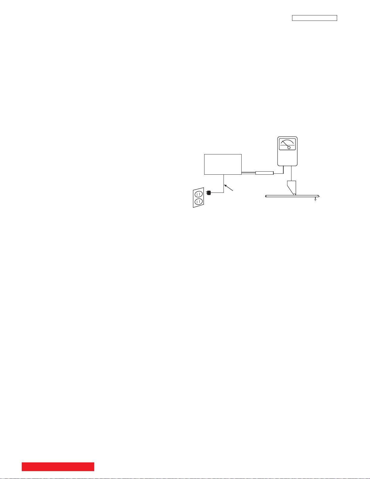
Leakage Current Hot Check
Plug the AC line cord directly into a 120V AC 60Hz outlet (do not use
an isolated transformer for this check).Turn the AC power ON. Using
a Leakage Current Tester (Simpson’s Model 228 or equivalent),
measure for current from all exposed metal parts of the cabinet
(antennas, screwheads, overlays, control shafts, etc.) particularly
any exposed metal
part having a return path to the chassis or to a
known earth ground (water pipe, conduit, etc.). Any current measured must not exceed 0.5 MIU.
(READING
SHOULD NOT
BE ABOVE
0.5 MIU)
AC LEAKAGE TEST
ANY MEASUREMENTS NOT WITHIN THE LIMITS OUTLINED
ABOVE ARE INDICATIVE OF A POTENTIAL SHOCK HAZARD
AND MUST BE CORRECTED BEFORE RETURNING THE
RECEIVER TO THE CUSTOMER.
Therefore, the following checks should be performed for the continued protection of the customer and service technician.
Leakage Current Cold Check
With the AC plug removed from the 120V AC 60Hz source, place
a jumper across the two plug prongs. Using an insulation tester
(DC500V), connect one lead to the jumpered AC plug and touch
the other lead to each exposed metal part (antennas, screwheads,
metal overlays, control shafts, etc.), particularly any exposed metal
part having a return path to the chassis should have a minimum
resistor reading of 2.4M
q. Any resistance value below or above this range indicates
5.2M
q and a maximum resistor reading of
an abnormality which requires corrective action. An exposed metal
part having a return path to the chassis will indicate an open circuit.
TABLE OF CONTENTS
2
PRODUCT SAFETY NOTICE
125V
6A
F901
LC48/B-LC47/B/K
Many electrical and mechanical parts in HITACHI television
receivers have special safety-related characteristics. These are
often not evident from visual inspection nor can the protection
afforded by them necessarily be obtained by using replacement
components rated for higher voltage, wattage, etc. Replacement
parts which have these special safety characteristics are identified
in this Service Manual.
Electrical components having such features are identified with an
! mark in the schematics and parts list in this Service Manual.
The use of a substitute replacement component which does not
have the same safety characteristics as the HITACHI-recommended replacement component, shown in the parts list in this Service
Manual, may create shock, fire, or other hazards.
Production safety is continuously under review and new instructions are issued from time to time. For the latest information,
always consult the current HITACHI Service Manual. A subscription to, or additional copies of HITACHI Service Manuals may be
obtained at a nominal charge from HITACHI Sales Corporation.
Ultraviolet Radiation
OPTIC UNIT:
receiver is the optic unit. The optic unit utilized in this chassis is
specially constructed to limit Ultraviolet Radiation emissions. For
continued Ultraviolet Radiation protection, the replacement optic
unit must be the same type as the original HITACHI-approved
type.
Service Personnel - WARNING
Eye damage may result from directly viewing the light produced by
the lamp used in this product. Always turn off lamp before opening optic unit. Ultraviolet radiation eye protection required during
servicing.
The primary source of Ultraviolet Radiation in this
When servicing or handling circuit boards and other components which contain lead in solder, avoid unprotected skin
contact with solder. Also, when soldering do not inhale any
smoke or fumes produced.
SAFETY NOTICE
USE ISOLATION TRANSFORMER
WHEN SERVICING
Components having special safety characteristics identified by
supplements and bulletins. Before servicing this product, it
is important that the service technician read and follow the
“Safety Precautions” and the “Product Safety Notices” in
this Service Manual.
For continued ultraviolet protection, replace optic unit with
original type or HITACHI equivalent type.
!
on the parts list in this service manual and its
POWER SOURCE
This television receiver is designed to operate on 120
Volts/60Hz, AC house current. Insert the power cord into
a 120 Volts/60Hz outlet.
NEVER CONNECT THE TV TO OTHER THAN THE
SPECIFIED VOLTAGE OR TO DIRECT CURRENT.
CAUTION!
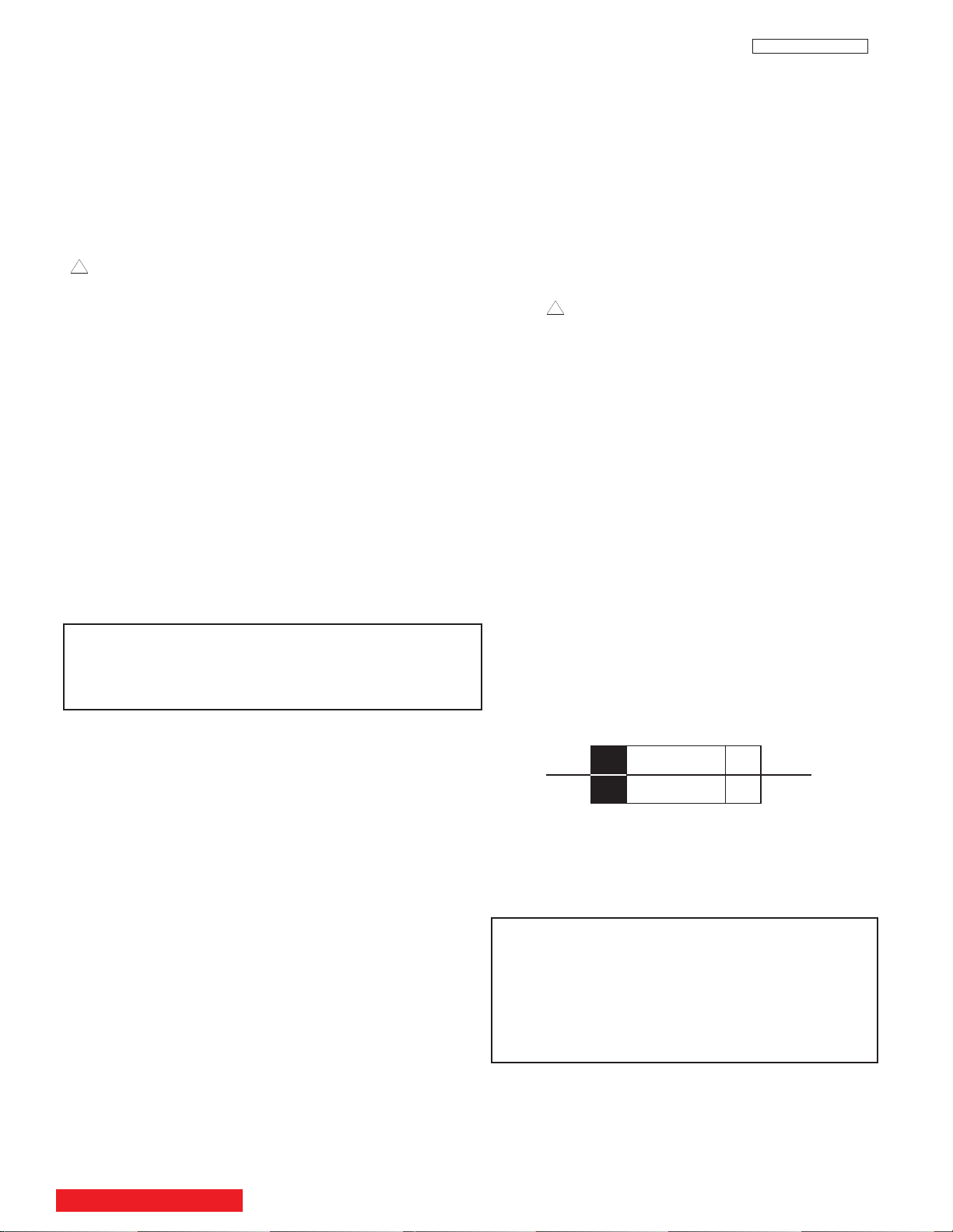
The following symbol near the fuse indicates fast operating fuse (to be replaced). Fuse ratings appear within the
symbol.
Example:
When troubleshooting and making test measurements in a receiver with an excessive high voltage problem, avoid being unnecessarily close to the optic unit and the high voltage component.
Do not operate the chassis longer than is necessary to locate the
cause of excessive voltage.
This Service Manual is intended for qualified service technicians; it is not meant for the casual do-it-yourselfer. Qualified
technicians have the necessary test equipment and tools, and
have been trained to properly and safely repair complex products such as those covered by this manual. Improperly performed repairs can adversely affect the safety and reliability of
the product and may void warranty. Consumers should not risk
trying to do the necessary repairs and should refer to a qualified service technician.
WARNING
Lead in solder used in this product is listed by the California Health
and Welfare agency as a known reproductive toxicant which may
cause birth defects or other reproductive harm (California Health
and Safety Code, Section 25249.5).
TABLE OF CONTENTS
F101
The rating of fuse F101 is 6.0A-125V.
Replace with the same type of fuse for continued protection against fire.
NOTE:
The lamp in this product contains Mercury.
Dispose of properly in accordance with applicable
environmental laws. For Recycling and Disposal
information, contact your respective governmental agencies or the Electronic Industries Alliance
at www.eiae.org (in the U.S.) or Electronic
Product Stewardship Canada at www.epsc.ca (in
Canada).
3

SERVICING PRECAUTIONS
CAUTION: Before servicing instruments covered by this service
data and its supplements and addenda, read and follow the SAFETY PRECAUTIONS on page 2 of this publication.
NOTE: If unforseen circumstances create conflict between the following SERVICING PRECAUTIONS and any of the SAFETY PRECAUTIONS on page 2 of this publication, always follow the SAFETY
PRECAUTIONS.
Remember: Safety First.
General Servicing Guidelines
1. Always unplug the instrument AC power cord from the AC power
source before:
a. Removing or reinstalling any component, circuit board,
module, or any other instrument assembly.
LC48/B-LC47/B/K
1. Immediately before handling any semiconductor component or
semiconductor-equipped assembly, drain off any electrostatic
charge on your body by touching a known earth ground.
Alternatively, obtain and wear a commercially available discharging wrist strap device, which should be removed for potential shock reasons prior to applying power to the unit under test.
2. After removing an electrical assembly equipped with ES
devices, place the assembly on a conductive surface such as
aluminum foil, to prevent electrostatic charge build-up or exposure of the assembly.
3. Use only a grounded-tip soldering iron to solder or desolder ES
devices.
b. Disconnecting or reconnecting any instrument electrical
plug or other electrical connection.
c. Connecting a test substitute in parallel with an electrolyt-
ic capacitor in the instrument.
CAUTION: A wrong part substitution or incorrect
polarity installation of electrolytic
capacitors may result in an
explosion hazard.
2. Do not spray chemicals on or near this instrument or any of its
assemblies.
3. Unless specified otherwise in these service data, clean electrical contacts by applying the following mixture to the contacts
with a pipe cleaner, cotton-tipped stick or comparable nonabrasive applicator: 10% (by volume) Acetone and 90% (by volume)
ispropyle alchohol (90%-99% strength).
CAUTION: This is a flammable mixture. Unless specified
otherwise in these service data, lubrication of
contacts is not required.
4. Do not defeat any plug/socket B+ voltage interlocks with which
instruments covered by this service data might be equipped.
4. Use only an anti-static type solder removal device. Some solder
removal devices not classified as “anti-static” can generate electrical charges sufficient to damage ES device.
5. Do not use freon-propelled chemicals. These can generate
electrical charges sufficient to damage ES devices.
6. Do not remove a replacement ES device from its protective
package until immediately before you are ready to install it.
(Most replacement ES devices are packaged with leads electrically shorted together by conductive foam, aluminum foil or comparable conductive material.)
7. Immediately before removing the protective material from the
leads of a replacement ES device, touch the protective material
to the chassis or circuit assembly into which the device will be
installed.
CAUTION: Be sure no power is applied to the chassis or
circuit, and observe all other safety precautions.
8. Minimize bodily motions when handling unpackaged replacement ES devices. (Otherwise harmless motion such as the
brushing together of your clothes fabric or the lifting of your foot
from a carpeted floor can generate static electricity sufficient to
damage an ES device.)
5. Do not apply AC power to this instrument and/or any of its electrical assemblies unless all solid-state device heat-sinks are correctly installed.
6. Always connect the test instrument ground lead to the appropriate instrument chassis ground before connecting the test instrument positive lead. Always remove the test instrument ground
lead last.
7. Use with this instrument only the test fixtures specified in this
service data.
CAUTION: Do not connect the test fixture ground strap to
any heatsink in this instrument.
Electrostatically Sensitive (ES) Devices
Some semiconductor (solid state) devices can be damaged easily by
static electricity. Such components commonly are called
Electrostatically Sensitive (ES) Devices. Examples of typical ES
devices are integrated circuits and some field-effect transistors and
semiconductor “chip” components. The following techniques should
be used to help reduce the incidence of component damage caused
by static electricity.
TABLE OF CONTENTS
4
LC48/B-LC47/B/K
Use Soldering Iron to Pry Leads
General Soldering Guidelines
1. Use a grounded-tip, low-wattage soldering iron and appropriate
tip size and shape that will maintain tip temperature within the
range 500°F to 600°F.
2. Use an appropriate lead free solder (see page 10). Lead solder
can be used, but there is a possibility of failure due to insufficient
strength of the solder.
3. Keep the soldering iron tip clean and well-tinned.
4. Thoroughly clean the surfaces to be soldered. Use a small wirebristle (0.5 inch or 1.25 cm) brush with a metal handle. Do not
use freon-propelled spray-on cleaners.
5. Use the following desoldering technique.
a. Allow the soldering iron tip to reach normal temperature
(500°F to 600°F).
b. Heat the component lead until the solder melts. Quickly
draw away the melted solder with an anti-static, suctiontype solder removal device or with solder braid.
CAUTION: Work quickly to avoid overheating the circuit
board printed foil.
6. Use the following soldering technique.
a. Allow the sodering iron tip to reach normal temperature
(500°F to 600°F).
b. First, hold the soldering iron tip and solder strand against
the component lead until the solder melts.
2. Draw away the melted solder with an anti-static suction-type sol
der removal device (or with solder braid) before removing the
IC.
Replacement
1. Carefully insert the replacement IC in the circuit board.
2. Carefully bend each IC lead against the circuit foil pad and
solder it.
3. Clean the soldered areas with a small wire-bristle brush. (It is
not necessary to reapply acrylic coating to areas.)
“Small-signal” Discrete Transistor Removal/Replacement
1. Remove the defective transistor by clipping its leads as close as
possible to the component body.
2. Bend into a “U” shape the end of each of three leads remaining on the circuit board.
3. Bend into a “U” shape the replacement transistor leads.
4. Connect to replacement transistor leads to the corresponding
leads extending from the circuit board and crimp the “U” with
long nose pliers to insure metal to metal contact, then solder
each connection.
Power Output Transistor Devices Removal/Replacement
1. Heat and remove all solder from around the transistor leads.
2. Remove the heatsink mounting screw (if so equipped).
c. Quickly move the soldering iron tip to the junction of the
component lead and the printed circuit foil, and hold it
there only until the solder flows onto and around both the
component lead and the foil.
CAUTION: Work quickly to avoid overheating the circuit
board printed foil or components.
d. Closely inspect the solder area and remove any excess
or splashed solder with a small wire-bristle brush.
IC Removal/Replacement
Some Hitachi unitized chassis circuit boards have slotted holes
(oblong) through which the IC leads are inserted and then bent flat
against the circuit foil. When holes are the slotted type, the following
technique should be used to remove and replace the IC. When working with boards using the familiar round hole, use the standard technique as outlined in paragraphs 5 and 6 above.
3. Carefully remove the transistor from the circuit board.
4. Insert new transistor in circuit board.
5. Solder each transistor lead, and clip off excess lead.
6. Replace heatsink.
Diode Removal/Replacement
1. Remove defective diode by clipping its leads as close as possilbe to diode body.
2. Bend the two remaining leads perpendicularly to the circuit
board.
3. Observing diode polarity, wrap each lead of the new diode
around the corresponding lead on the circuit board.
4. Securely crimp each connection and solder it.
5. Inspect (on the circuit board copper side) the solder joints of
the two “original leads”. If they are not shiny, reheat them
and, if necessary, apply additional solder.
Removal
1. Desolder and straighten each IC lead in one operation by
gently prying up on the lead with the soldering iron tip as the
solder melts.
5
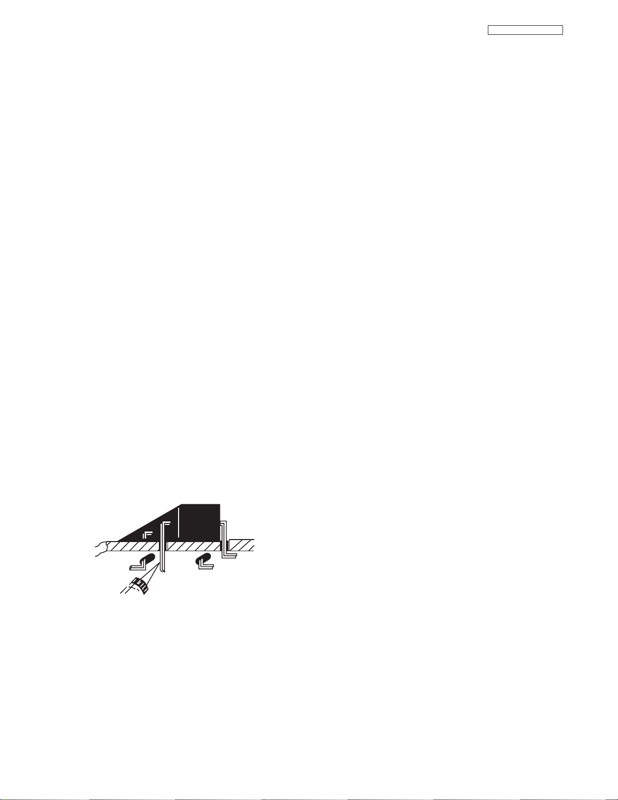
Fuses and conventional Resistor Removal/Replacement
CRIMP AND
SOLDER
BARE JUMPER
WIRE
Install Jumper Wire and Solder
DEFECTIVE
COPPER
REMOVED
Insulated Jumper Wire
1. Clip each fuse or resistor lead at top of circuit board hollow
stake.
2. Securely crimp leads of replacement component around stake
1/8 inch from top.
3. Solder the connections.
CAUTION: Maintain original spacing between the replaced
component and adjacent components and the
circuit board, to prevent excessive component
temperatures.
Circuit Board Foil Repair
Excessive heat applied to the copper foil of any printed circuit board
will weaken the adhesive that bonds the foil to the circuit board,
causing the foil to separate from, or “lift-off” the board. The following
guidelines and procedures should be followed whenever this condition is encountered.
LC48/B-LC47/B/K
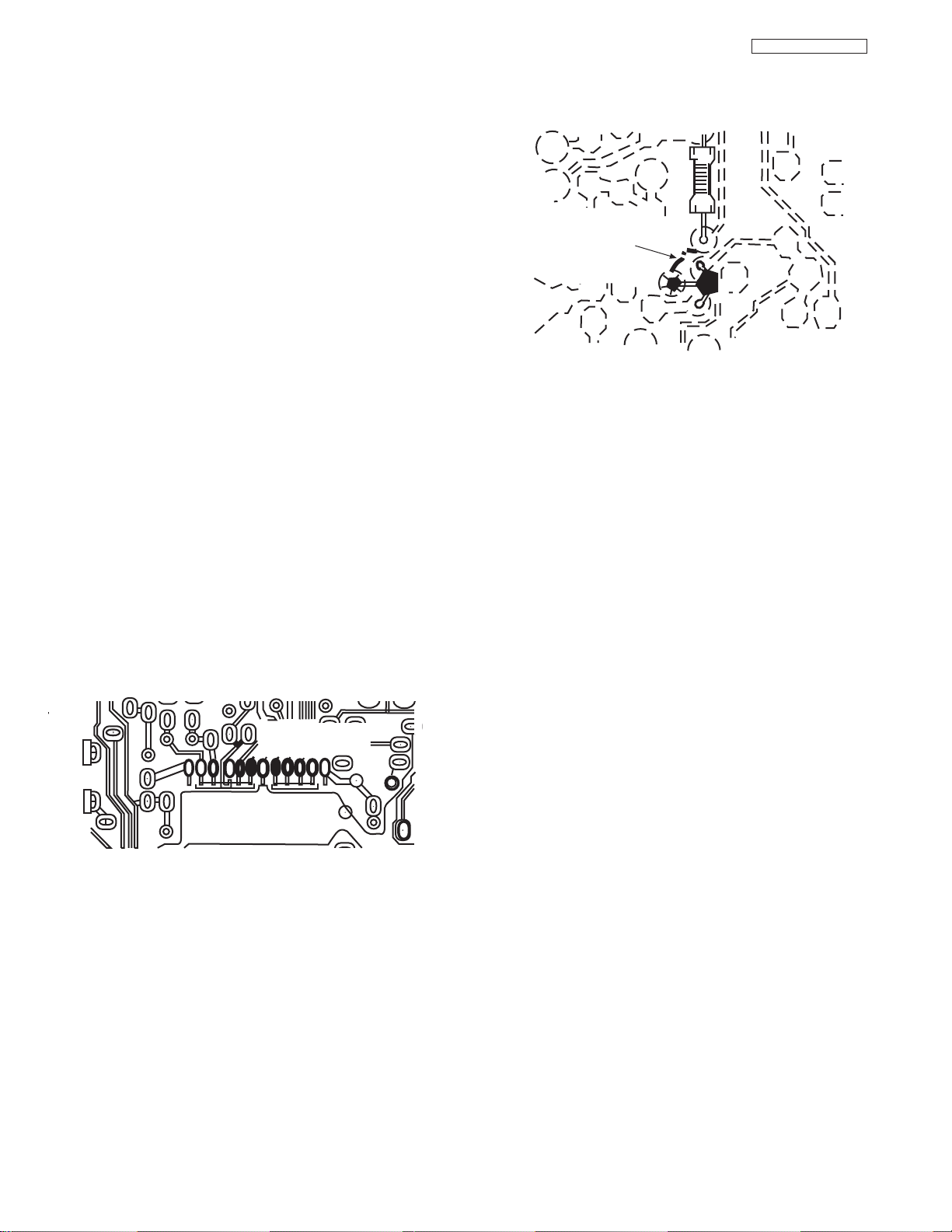
At Other Connections
Use the following technique to repair defective copper pattern at con-
In Critical Copper Pattern Areas
High component/copper pattern density and/or special voltage/current characteristics make the spacing and integrity of copper pattern
in some circuit board areas more critical than in others. The circuit
foil in these area is designated as Critical Copper Pattern. Because
Critical Copper Pattern requires special soldering techniques to
ensure the maintenance of reliability and safety standards, contact
your Hitachi personnel.
At IC Connections
To repair defective copper pattern at IC connections, use the following procedure to install a jumper wire on the copper pattern side of
the circuit board. (Use this technique only on IC connections.)
1. Carefully remove the damaged copper pattern with a sharp
knife. (Remove only as much copper as absolutely necessary.)
2. Carefully scratch away the solder resist and acrylic coating (if
used) from the end of the remaining copper pattern.
3. Bend a small “U” in one end of a small-gauge jumper wire and
carefully crimp it around the IC pin. Solder the IC connection.
4. Route the jumper wire along the path of the cut-away copper
pattern and let it overlap the previously scraped end of the good
copper pattern. Solder the overlapped area, and clip off any
excess jumper wire.
nections other than IC Pins. This technique involves the installation
of a jumper wire on the component side of the circuit board.
1. Remove the defective copper pattern with a sharp knife.
Remove at least 1/4 inch of copper, to ensure hazardous condition will not exist if the jumper wire opens.
2. Trace along the copper pattern from both wire sides of the pattern break and locate the nearest component directly connected to the affected copper pattern.
3. Connect insulated 20-gauge jumper wire from the nearest component on one side of the pattern break to the lead of the nearest component on the other side. Carefully crimp and solder the
connections.
CAUTION: Be sure the insulated jumper wire is dressed so
that it does not touch components or sharp
edges.
Frequency Synthesis (FS) Tuning Systems
1. Always unplug the instrument AC power cord before disconnecting or reconnecting FS tuning system cables and before
removing or inserting FS tuning system modules.
2. The FS tuner must never be disconnected from the FS tuning
control module while the power is applied to the instrument.
3. When troubleshooting intermittent problems that might be
caused by defective cable connection(s) to the FS tuning system, remove the instrument AC power as soon as the defective
connector is found and finish confirming the bad connection with
a continuity test. This procedure will reduce the probability of
electrical overstress of the FS system semi-conductor components.
6
LC48/B-LC47/B/K
NOTE: These components are affixed with glue. Be careful not to break or damage any foil under the
component or at the pins of the ICs when removing. Usually applying heat to the component for a short
time while twisting with tweezers will break the component loose.
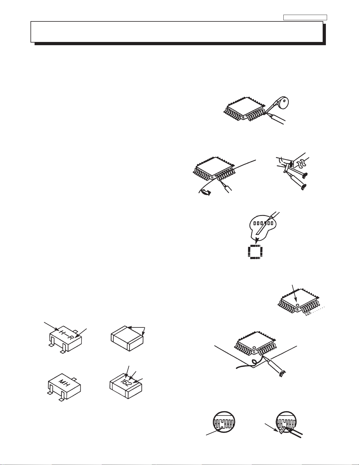
Leadless Chip Components
(surface mount)
Chip components must be replaced with identical chips due
to critical foil track spacing. There are no holes in the board
to mount standard transistors or diodes. Some chip capacitor or resistor board solder pads may have holes through the
board, however the hole diameter limits standard resistor
replacement to 1/8 watt. Standard capacitors may also be
limited for the same reason. It is recommended that identical
chip components be used. .
Chip resistors have a three digit numerical resistance code 1st and 2nd significant digits and a multiplier. Example: 162
= 1600 or 1.6KΩ resistor, 0 = 0Ω (jumper).
Chip capacitors generally do not have the value indicated on
the capacitor.The color of the component indicates the general range of the capacitance.
Chip transistors are identified by a two letter code. The first
letter indicates the type and the second letter, the grade of
transistor.
Chip diodes have a two letter identification code as per the
code chart and are a dual diode pack with either
common anode or common cathode. Check the parts list for
correct diode number.
Component Removal
1. Use solder wick to remove solder from component end
caps or terminals.
2. Without pulling up, carefully twist the component with
tweezers to break the adhesive.
3. Do not reuse removed leadless or chip components
since they are subject to stress fracture during removal.
Chip Component Installation
1. Put a small amount of solder on the board soldering
pads.
2. Hold the chip component against the soldering pads
with tweezers or with a miniature alligator clip and apply
heat to the pad area with a 30 watt iron until solder
flows. Do not apply heat for more than 3 seconds
How to Replace Flat-lC
—Required Tools—
• Soldering iron • iron wire or small awl
• De-solder braids • Magnifier
1. Remove the solder from all of the pins of a Flat-lC by
using a de-solder braid.
Flat-IC
2. Put the iron wire under the pins of the Flat-lC and pull it
in the direction indicated while heating the pins using a
soldering iron. A small awl can be used instead of the
iron wire.
Iron
Wire
Pull
Soldering
Iron
Soldering
3. Remove the solder from all of the pads of the FlatlC by using
a de-solder braid.
De-Solder
Braid
Flat-IC
4. Position the new Flat-lC in place (apply the pins of the
Flat-lC to the soldering pads where the pins need to be
soldered). Properly determine the
positions of the soldering pads
and pins by correctly aligning the
polarity symbol.
De-Solder
Braid
Soldering
Iron
Awl
Iron
Soldering
Iron
Polarity Symbol
TYPE
B
ANODES
Chip Components
C
E
MH DIODE
TRANSISTOR
COMMON CATHODE
GRADE
SOLDER CAPS
1ST DIGIT
RESISTOR
SOLDER
CAPS
CAPACITOR
2ND DIGIT
MULTIPLIER
= 1600 = 1.6K
5. Solder all pins to the soldering pads using a fine tipped
soldering iron.
Solder
Soldering
Iron
6. Check with a magnifier for solder bridge between the
pins or for dry joint between pins and soldering pads. To
remove a solder bridge, use a de-solder braid as shown
in the figure below.
De-Solder
Braid
Bridge
Solder
Soldering
7
Iron
Information for service about lead-free solder introduction
Hitachi introduced lead-free solder to conserve the "Earth Environment".
Please refer to the following before servicing.
(1) Characteristic of lead-free solder
Melting point of lead free solder is 40-50
o
C higher than solder containing lead.
(2) Solder for service
Following composition is reccomended.
" Sn - 3.0Ag - 0.5Cu " , or " Sn - 0.7 Cu "
Lead solder can be used, but there is a possibility of failure due to insufficient strength of the solder.
Caution when using solder containing lead.
Please remove previous solder as much as possible from the soldering point.
When soldering, please perfectly melt the lead-free solder to mix well with the previous solder.
(3) Soldering iron for lead-free solder.
Melting point of lead-free solder is higher than solder containing lead.
Use of a soldering tool "with temperature control" and "with much thermal capacitance" is reccomended.
(Reccomended temperature control : 320
o
C - 450oC)
Reccomended temperature
PWB with chip parts
320
o
C +/- 30oC
PWB without chip parts
380
o
C +/- 30oC
Chassis, metal, shield etc.
420
o
C +/- 30oC
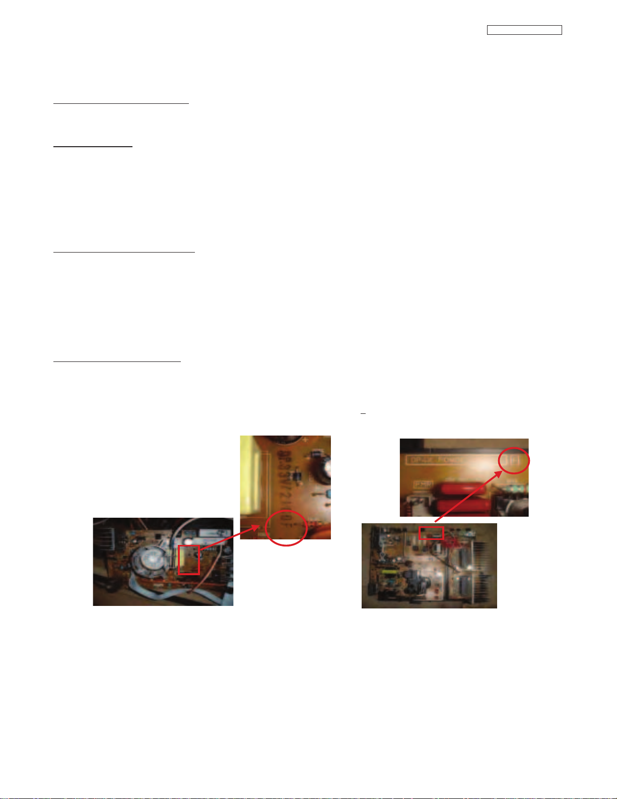
(4) Identification of lead-free PWB
2003 models >> not applied
2003 models >> mixed
2004 models >> lead-free solder is intoduced
On lead-free PWB, "F" is added at the end of stamp on PWB. (e.g. DP33W
F)
LC48/B-LC47/B/K
8
LC48/B-LC47/B/K
AGENCY REGULATORY
INFORMATION
Modifications
The FCC requires the user to be notified that any changes or modifications made to this device that are not expressly
approved by Hitachi Home Electronics (America), Inc. may void the user’s warranty.
Cables
Any cables that are supplied with the system must be replaced with identical cables in order to assure compliance with
FCC rules. Order Hitachi spares as replacement cables.
Declaration of Conformity
This device complies with Part 15 of the FCC Rules. Operation is subject to the following two conditions: (1) this device
may not cause harmful interference and (2) this device must accept any interference received, including interference
that may cause undesired operation.
Cable Compatible Television Apparatus- Tèlèvision câblocompatible, Canada.
Notes on Closed Caption:
This television receiver will display television closed captioning, ( or ), in accordance with paragraph 15.119
of the FCC rules.
For questions regarding this declaration, contact:
Hitachi America, LTD.
Home Electronics Division
900 Hitachi Way
Chula Vista, CA 91914
Tel. 1-800-448-2244 (1-800-HITACHI)
ATTN: CUSTOMER RELATIONS
TABLE OF CONTENTS
9

LC48/B-LC47/B/K
TO GO TO AN ADJUSTMENT, CLICK ON ITS HEADING BELOW
TABLE OF CONTENTS
I. SPECIFICATIONS ..................................................................................................................................................................11
1. Features..............................................................................................................................................................................11
2. Aspect Key Operation ........................................................................................................................................................12
II. FEATURES AND FUNCTIONS ..............................................................................................................................................15
1. Front Panel Controls ..........................................................................................................................................................15
2. Rear Panel Jacks................................................................................................................................................................17
3. Lamp Replacement ............................................................................................................................................................22
4. On-Screen-Display Features ..............................................................................................................................................26
4.1 Video Setting ..............................................................................................................................................................29
4.2 Channel Manager ......................................................................................................................................................33
4.3 Set-Up-Upgrades........................................................................................................................................................35
III. ASSEMBLED P.W.B. ADJUSTMENT....................................................................................................................................36
1. Memory Initialization ..........................................................................................................................................................36
2. Factory Reset ....................................................................................................................................................................37
3. Raster Position Adjustment ................................................................................................................................................38
4. Display Area Specification..................................................................................................................................................39
5. Amplitude Adjustment ........................................................................................................................................................40
6. Sub-Contrast Adjustment....................................................................................................................................................40
7. Ghost Adjustment ..............................................................................................................................................................41
8. V.COM (Flicker) Adjustment................................................................................................................................................41
9. NASH (Vertical Line) Adjustment........................................................................................................................................41
10.(Gamma) White Balance Adjustment..................................................................................................................................42
11.Color (White) Uniformity Adjustment ..................................................................................................................................43
12.Door Protection Operation Check ......................................................................................................................................44
13.Lamp Holder Protection Operation Check..........................................................................................................................44
14.High Temperature Protection Operation Check/White Balance Specification ....................................................................44
2
15.I
C Parameter ....................................................................................................................................................................45
TABLE OF CONTENTS
10
LC48/B-LC47/B/K
I. SPECIFICATION
1. Features:
• Superfine Picture Quality
1280 Line Horizontal Resolution
• Remote (Controls many PVR/VCR brands, cable boxes, satellite boxes, and other audio equipment).
• New Easy-to-Use (3-Language) On-Screen Menu
• Full Set of Input Jacks, including S-VIDEO
• COMPONENT VIDEO: Y-P
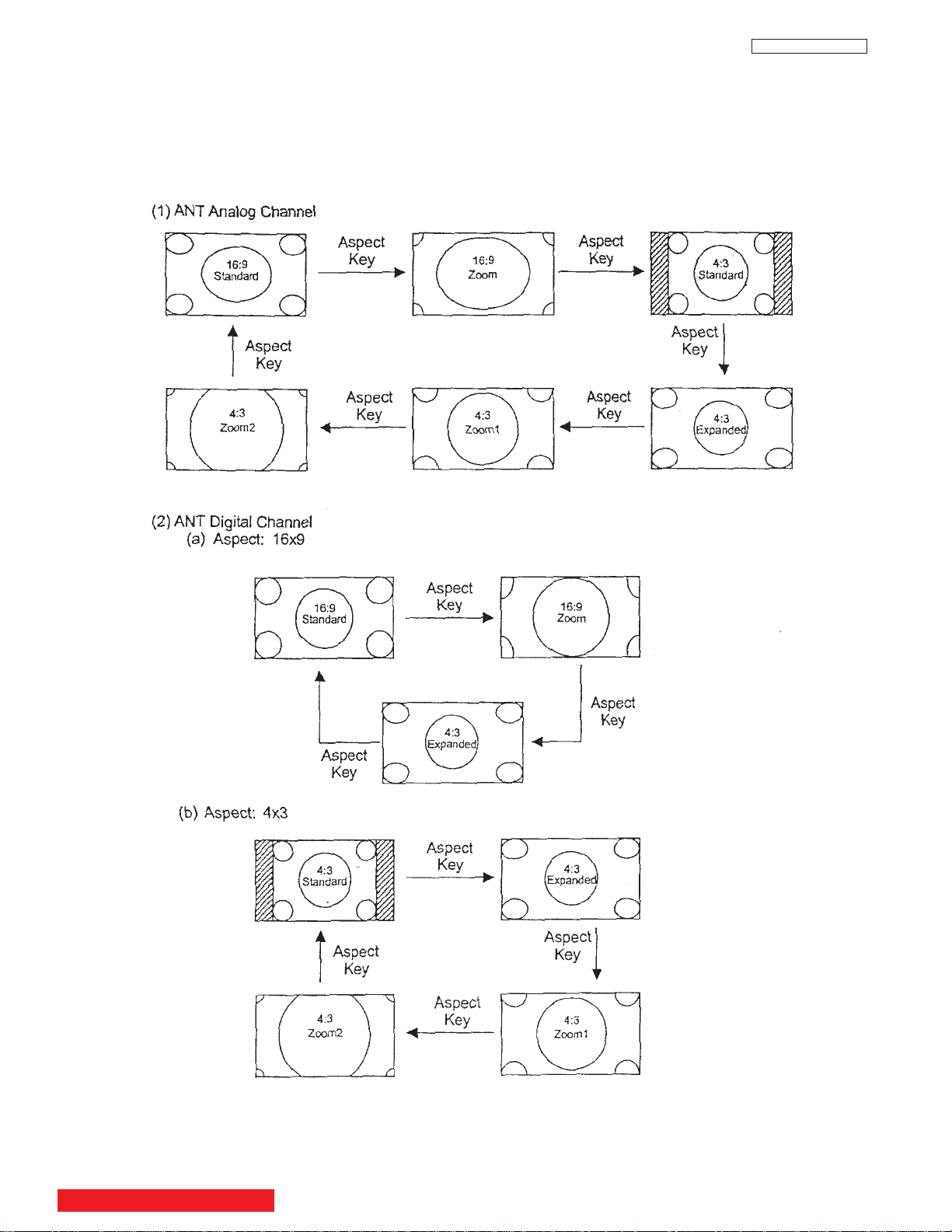
• Six Aspect Modes
• Closed Caption Decoder
• 2-Tuner Picture in Picture
• 2 Antenna Inputs (Either for Analog/Digital)
• Video Input Sensor
• 3 Dimensional Y/C Comb Filter
• Compatible with 1080i, 720p, 480p and 480i input signals.
• HDMI (High Definition Multimedia Interface) (High Bandwidth Digital Content Protection V1.1 compatible).
• Digital Audio Output (Dolby
• Photo Input (for your digital camera).
• CableCARDTMcompatible - Contact your local cable operator for more information.
• Technology.
*Licensed by BBE Sound, Inc. under USP4638258, 5510752 and 5736897. BBE and BBE symbol are registered
trademarks of BBE Sound, Inc. Manufactured under license from BBE Sound, Inc.
• Technology.
*SRS and symbol are trademarks of SRS Labs, Inc. SRS technology is incorporated under license from SRS Labs, Inc.
• Technology.
*Manufactured under license from Dolby Laboratories. “Dolby” and the double-D symbol are trademarks of Dolby
Laboratories.
• Technology
HDMI, the HDMI logo and High-Definition Multimedia Interface are trademarks or registered trademarks of HDMI Licensing LLC.
*
B/PR
®
Digital and PCM)
Inputs:
Power Input . . . . . . . . . . . . . .AC 120V, 60Hz
•
Stand-by Power . . . . . . . . . . . . . . . . . . .0.6W
•
• Power Consumption
- Refer to rear panel at the back of the T.V.
• Antenna input impedance . . . . . . . . .75 Ohm
• Channel coverage . . . . . . . . . . . . . . . .181ch.
VHF-Band . . . . . . . . . . . . . . . . . . . . . .2 ~ 13
UHF-Band . . . . . . . . . . . . . . . . . . . . .14 ~ 69
CATV Mid Band . . . . . . . . . . . . . . .A-5 ~ A-1
. . . . . . . . . . . . . . . . . . . . . . . . . . . .A-I
Super Band . . . . . . . . . . . . . . . . . . . . . .J-W
Hyper Band . . . . . . . . . . . . . . . .W+1 - W+28
Ultra Band . . . . . . . . . . . . . . . .W+29 - W+84
• Video . . . . . . . . . . . . . . . . .1.0Vp-p, 75 Ohm
• S-Video
Luminance (Y) . . . . . . . . . . .1.0Vp-p, 75 Ohm
Chrominance (C) . . . . . . .0.286Vp-p, 75 Ohm
• Component Video
Luminance (Y) . . . . . . . . . . . . . . .1.0Vp-p, 75 Ohm
Chrominance (PB/PR) . . . . . . . . .0.7Vp-p, 75 Ohm
• Audio input Impedance . . . . . . . . . .47k Ohm
• Average input level . . . . . . . . . . . . . . . . .470mVrms
• HDMI . . . . . . . . . . . . . . . . . . . . . . . . . . .HDMI 19pin
Outputs:
• Video . . . . . . . . . . . . . . . . . . . . . . . . . . . . . . . . . . .1.0Vp-p. 75 Ohm
• Audio (Fixed) . . . . . . . . . . . . . . . . . . . . . . . . . . .470mVrms, 1k Ohm
• S-Video
Luminance (Y) . . . . . . . . . . . . . . . . . . . . .1.0Vp-p, 75 Ohm
Chrominance (C) . . . . . . . . . . . . . . . . .0.286Vp-p, 75 Ohm
• Optical Out (Digital Audio) . . . . . . . . . . .1 optical connector
Dimensions:
Height (in.) Width (in.) Depth (in.) Weight (lbs.)
(mm) (mm) (mm) (kg)
42V710/715 30 7/16 47 6/8 15 1/16 28 11/16
50V710/715 35 1/2 54 5/8 16 3/8 114
60V710/715 40 1/4 63 3/8 20 1/2 139.0
50VS810 28 11/16 55 3/8 16 6/16 110.2
60VS810 33 9/16 64 1/8 19 1/16 132.3
70VS810 44 1/8 73 9/16 21 5/8 182
772.5 1214.0 382.0 36.0
901.0 1,387.0 415 51.7
1,023.0 1,609.0 520 63
728.0 1,407.0 415.8 50.0
853.0 1,629.0 483.8 60.0
1,120.0 1,868.0 550.0 82.5
NOTE: Due to improvements, specifications in this operating
guide are subject to change without notice.
BACK TO ADJUSTMENTS
11
I. SPECIFICATION
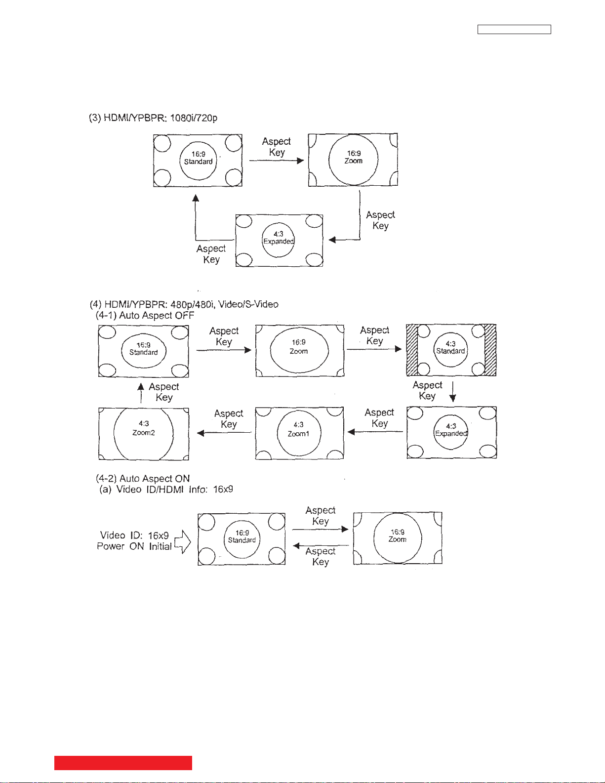
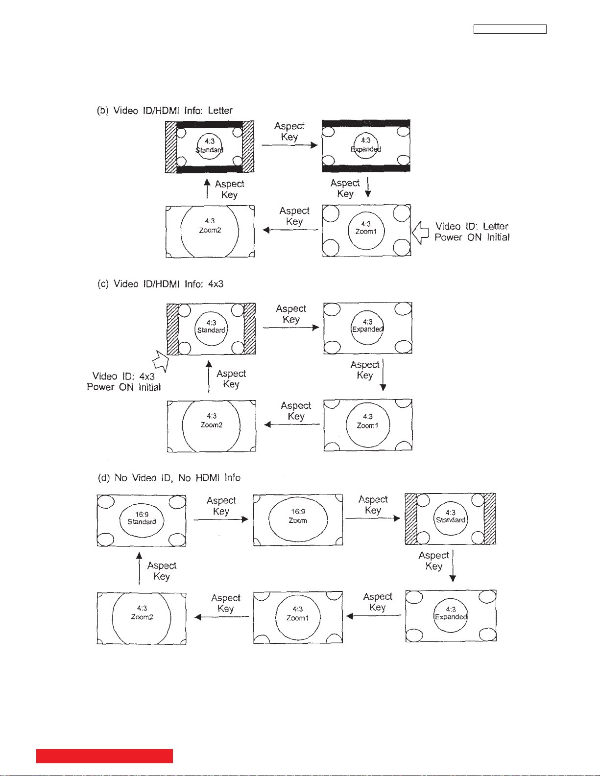
2. Aspect Key Operation
LC48/B-LC47/B/K
BACK TO ADJUSTMENTS
12
I. SPECIFICATION
LC48/B-LC47/B/K
BACK TO ADJUSTMENTS
13
I. SPECIFICATION
LC48/B-LC47/B/K
BACK TO ADJUSTMENTS
14
II. FEATURES AND FUNCTIONS
INPUT/EXIT
VOL-
VOL+
CH-
CH+
E
F
G
H
f
b
d
e
g
g
ij
k
MENU/SELECT
POWER
S-VIDEO
VIDEO
AUDIO
L/MONO
R
INPUT 5
PHOTO
INPUT
c
h
a
g
i
gk
j
INPUT 5
S-VIDEO
EXIT
INPUT
SELECT
MENUVOL- VOL+ CH- CH+
EH
c
f
a
b
d
e
VIDEO
AUDIO
L/MONO
R
PHOTO INPUT
PUSH
PUSH
h
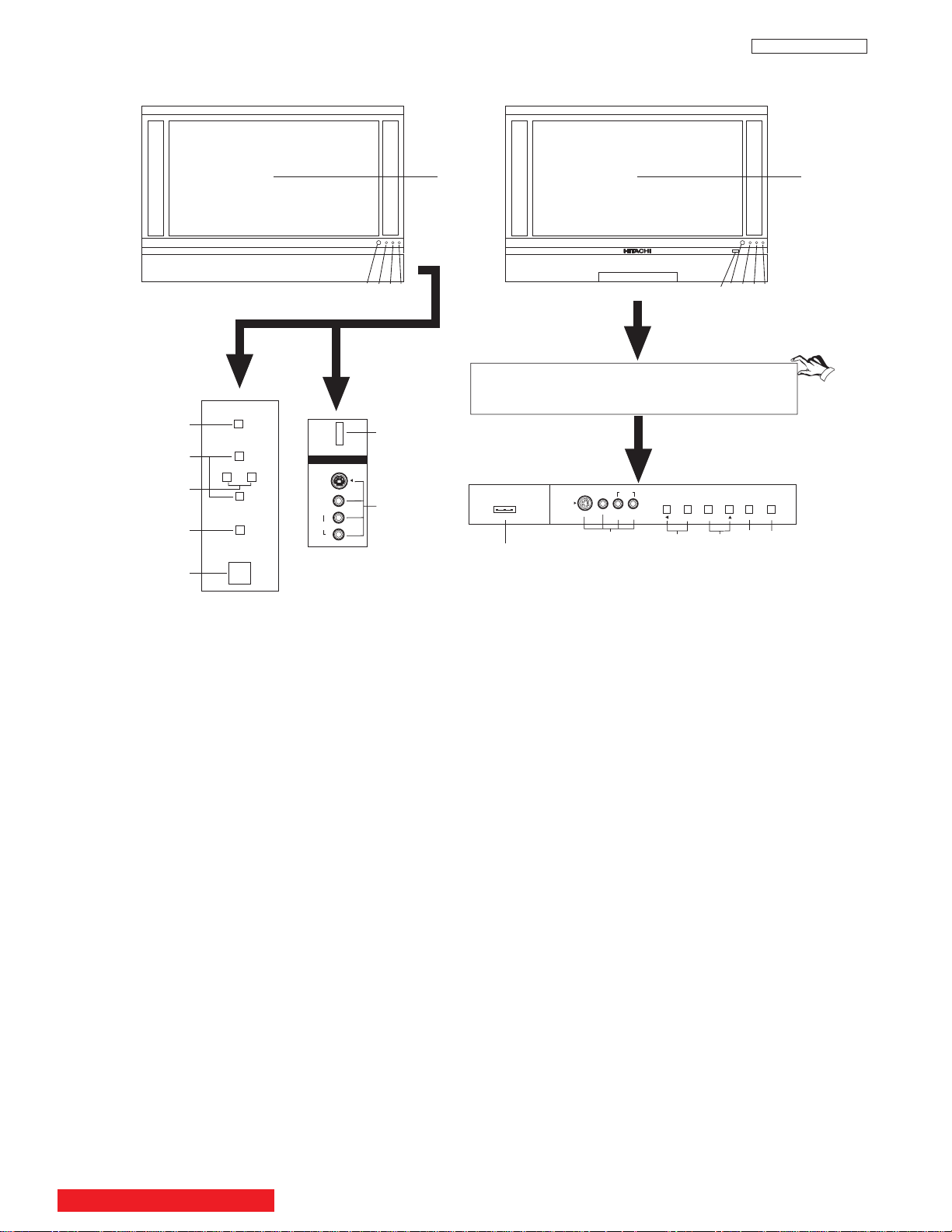
1.0 FRONT PANEL CONTROLS
LC48/B-LC47/B/K
MODELS: 42V710 / 42V715
50VS810 / 60VS810
MODELS: 50V710 / 50V715
60V710 / 60V715
a MENU/SELECT button
This button allows you to enter the MENU, making it possible to set TV features to your preference without using the remote. This
button also serves as the SELECT button when in MENU mode.
b INPUT/EXIT button
Press this button to display the input menu, Ant A/B, INPUT:1,2,3,4,5 or Photo Input. This button also serves as the EXIT button
when in MENU mode.
c CHANNEL selector
Press these buttons until the desired channel appears in the top right corner of the TV screen. These buttons also serve as
the cursor down (
H) and up (G) buttons when in MENU mode.
d VOLUME level
Press these buttons for your desired sound level. The volume level will be displayed on the TV screen. These buttons also serve
as the cursor left (F) and right (E) buttons when in MENU mode. When the TV power is turned OFF at a volume level 31 or greater,
the volume level will default to 30 when the TV is turned ON. However, if it is set to a level 30 or less, the volume level will be at the
level it was set when the TV is turned ON.
e SIDE INPUT JACKS (INPUT 5)
Use these audio/video jacks for a quick hook-up from a camcorder or VCR to instantly view your favorite show or new recording.
Press the INPUT/EXIT button on the front control panel until VIDEO: 5 appears in the top right corner of the TV screen. If you have
mono sound, insert the audio cable into the left audio jack.
f PHOTO INPUT
Insert USB cable from your Digital Camera to view your digital still pictures.
g IR RECEIVER sensor
The screen area acts as the IR receiver (remote sensor). When using the remote control, point it towards the screen for best
response.
h POWER button
Press this button to turn the TV on or off.
BACK TO ADJUSTMENTS
15
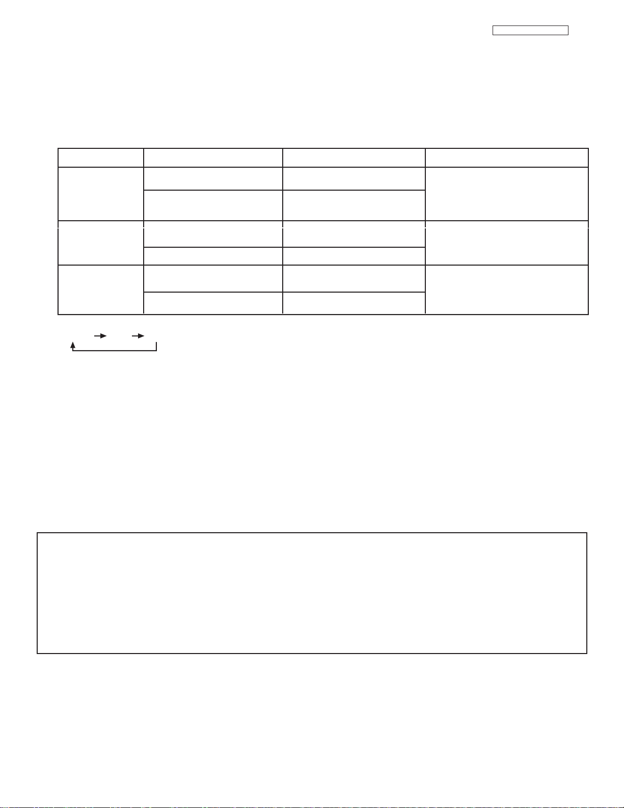
LC48/B-LC47/B/K
NO LAMP LIGHT
or BROKEN LAMP
WRONG LAMP UNIT
ASSEMBLY / LAMP
DOOR OPEN
Too hot inside the
OPTIC unit
COOLING FAN STOPPED
NORMAL
OPERATION
COOL DOWN
LIGHT ON
BLINKING
LIGHT ON
BLINKING
LIGHT ON
SLOWLY BLINKING
INDICATOR INDICATION MEANING ACTION
LAMP LED
TEMP
LED
POWER
Need to replace if
LAMP still does not light by
“Power On” again.
Check assembly condition of
LAMP UNIT
Call for Service
NOTES:
1.
2. If the LAMP, TEMP, and POWER LED are blinking in the order below, the television is warming up.
3. Your Hitachi LCD Rear Projection Television may appear to be OFF when it is set to input 1 ~ input 5 and the video
signal is not received from the input jacks. Please make sure the Blue Power light indicator is not lit (OFF) when
you are not watching for long lasting performance.
4. Your Hitachi LCD Rear Projection Television has an internal lamp that lights up the TV screen. Make sure to turn off
the Power when you do not watch the LCD Rear Projection Television for longer lamp life.
POWER TEMP LAMP
II. FEATURES AND FUNCTIONS
1.0 FRONT PANEL CONTROLS (CONT.)
i POWER light
This light is on during normal operation.
Light Blinking Slowly (2 seconds): television lamp is cooling down. It takes 12-15 seconds to warm up and about 2 minutes to cool
down.
j TEMP indicator
This light is off during normal operation.
If this indicator is lit, the optic unit is too hot. If this indicator is blinking, the cooling fan has stopped. Please call service.
k LAMP indicator - NORMAL OPERATION INDICATOR IS OFF
If light is lit, the lamp has failed. See page 19-22 for lamp replacement procedure. Consult your Hitachi dealer for proper part.
If light is blinking, lamp cover is not assembled securely after replacement.
IMPORTANT NOTES:
1. A small number of missing, discolored, or lit all the time dots or pixels is characteristic of TFT LCD technology due to the
manufacturing process irrespective of manufacturer.
2. Since LCD Rear PTV incorporates a high pressure lamp to display an image, it may take about one minute for the picture to
become stable, after the power has been turned on. After extended use, the picture may darken, the color may look unusual,
or the lamp “goes out,” (burns out). You may hear a “pop” sound when the lamp “goes out.” These are common
characteristics of the lamp, and should not be considered defective.
3. LCD Rear PTV incorporates an advanced cooling fan system to prevent from overheating. If you hear the cooling fan, it should
not be considered defective.
4. If you hear a “cracking” sound from the TV cabinet, it is due to the TV’s cabinet expanding and contracting due to room
temperature changes. It has no effect on the TV’s functions.
16
a
b
c
d
e
f
g
h
k
i
Apparatus Claims of U.S. Patent Nos.
4,631,603; 4,577,216; 4,819,098;
4,907,093; and 6,381,747 licensed
for limited viewing uses only.
12345
9876
j
a
b
c
d
e
f
g
h
k
i
Apparatus Claims of U.S. Patent Nos.
4,631,603; 4,577,216; 4,819,098;
4,907,093; and 6,381,747 licensed
for limited viewing uses only.
12345
9876
j
HDMI 2
ANT A
S-VIDEO
R
L
VIDEO
AUDIO
(MONO)
(MONO) (MONO) (MONO)
P
R
P
B
Y/
VIDEO
Y/
VIDEO
P
R
P
B
MONITOR OUT INPUT 4 INPUT 3
INPUT 2 INPUT 1
HDMI 1
RS232C
ANT B
Upgrade Card
CableCARD
(Top of card faces right)
OPTICAL OUT
Digital Audio
AUDIO
TO HI-FI
TV AS CENTER
ANT A
S-VIDEO
R
L
VIDEO
AUDIO
(MONO)
(MONO) (MONO) (MONO)
P
R
P
B
Y/
VIDEO
Y/
VIDEO
P
R
P
B
MONITOR OUT INPUT 4 INPUT 3
INPUT 2 INPUT 1
HDMI 1
RS232C
ANT B
Upgrade Card
CableCARD
(Top of card faces right)
OPTICAL OUT
Digital Audio
AUDIO
TO HI-FI
TV AS CENTER
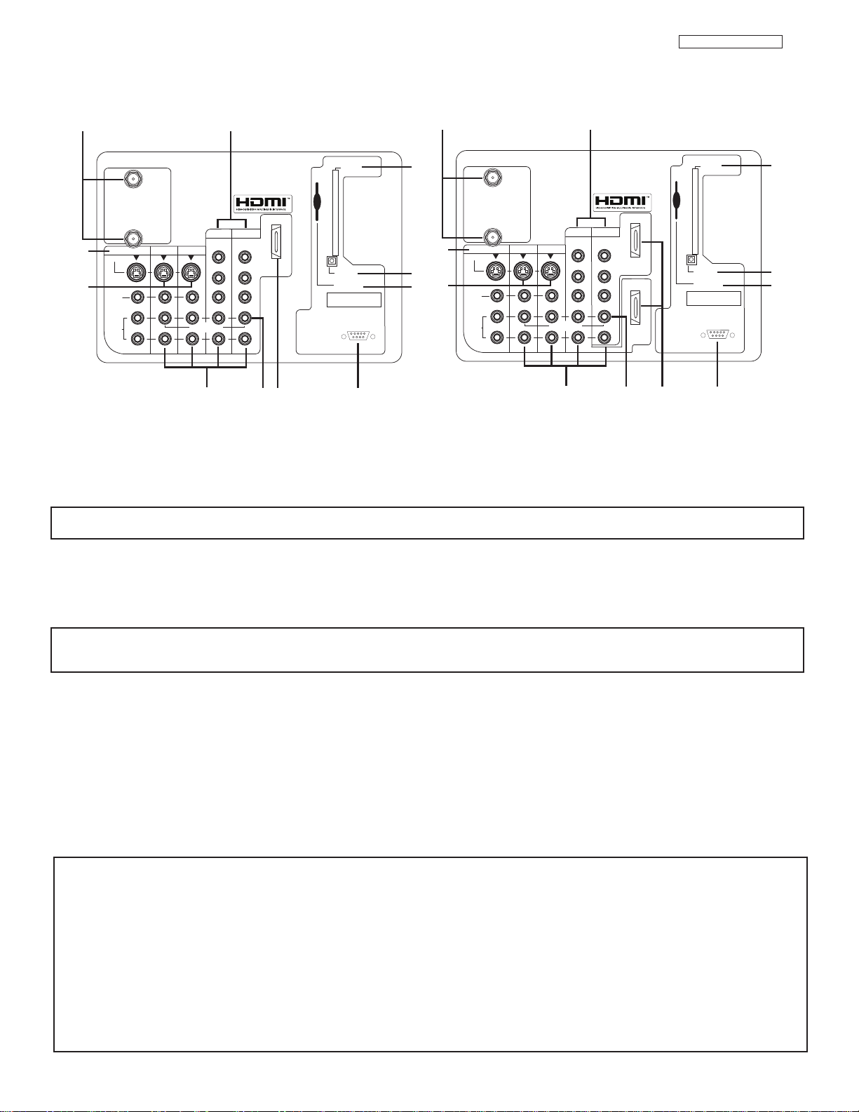
II. FEATURES AND FUNCTIONS
2.0 REAR PANEL JACKS
LC48/B-LC47/B/K
Models: 42V710/50V715/60V715
Models: 50VS810/60VS810
a Antenna Input
ANT A
- A 75-Ohm RF antenna or CATV (Cable TV) input. ANT A can be displayed as a main picture or sub-picture.
ANT B- A 75-Ohm RF antenna input. ANT B can only be displayed as a main picture. ANT B cannot be displayed as a
NOTE: You may ask your local cable company whether DTV services are available.
sub-picture.
b Audio/Video Inputs 1, 2, 3 and 4
By using the INPUTS button and CURSOR PAD of the remote control you can select each video source. Use the audio and video
inputs to connect external devices, such as VCRs, camcorders, laserdisc players, DVD players etc. (If you have mono sound, insert
the audio cable into the left audio jack).
NOTE: You may use VIDEO or S-VIDEO inputs to connect to INPUT 3 and 4, but only one of these inputs may be used at a
time.
c MONITOR OUT
These jacks provide fixed or variable audio and video signals which are used for recording. Use the S-VIDEO Output for high
quality video output.
d S-VIDEO Inputs 3 and 4
Inputs 3 and 4 provide S-VIDEO (Super Video) jacks for connecting equipment with S-VIDEO output capability.
e Component:Y-P
BPR
Inputs
Inputs 1 and 2 provide Y-PBPRjacks for connecting equipment with this capability, such as a DVD player or Set Top Box. You may
use composite video signal for both inputs.
NOTES: 1. Do not connect composite VIDEO and S-VIDEO to Input 3, 4 or 5 at the same time. S-VIDEO has priority
over VIDEO input.
Your component outputs may be labeled Y, B-Y, and R-Y. In this case, connect the components B-Y output to the TV’s PBinput and
2.
the components R-Y output to the TV’s PRinput.
3. Your component outputs may be labeled Y- CBCR. In this case, connect the component CBoutput to the TV’s PBinput and the
component CRoutput to the TV’s PRinput.
4. It may be necessary to adjust TINT to obtain optimum picture quality when using the Y-PBPR inputs.
5. To ensure no copyright infringement, the MONITOR OUT output will be abnormal, when using the Y-PBPRjacks.
6. Input 1 and Input 2 (Y/VIDEO) can be used for composite video and component video input.
17
LC48/B-LC47/B/K
II. FEATURES AND FUNCTIONS
2.0 REAR PANEL JACKS (CONT.)
f HDMI1 (High Definition Multimedia Interface) (INPUT 1)
About HDMI
HDMI is the next-generation all digital interface for consumer electronics. HDMI enables the secure distribution of uncompressed
high-definition video and multi-channel audio in a single cable. Because digital television (DTV) signals remain in digital format,
HDMI assures that pristine high-definition images retain the highest video quality from the source all the way to your television
screen.
HDMI 2 (INPUT 2)
Extra HDMI input that is only available in models 50VS810 and 60VS810.
Use the HDMI input for your external devices such as Set-Top-Boxes or DVD players equipped with an HDMI output connection.
HDMI, the HDMI logo and High-Definition Multimedia Interface are trademarks or registered trademarks of HDMI Licensing LLC.
NOTES: 1. The HDMI input is not intended for use with personal computers.
2. Only DTV formats such as 1080i, 720p, 480i and 480p are available for HDMI input.
g Optical Out (Digital Audio)
This jack provides Digital Audio Output for your audio device that is Dolby®Digital and PCM compatible, such as an audio amplifier.
NOTE:
*Manufactured under license from Dolby Laboratories. “Dolby” and the double-D symbol are trademarks of Dolby
Laboratories.
h Upgrade Card
This card slot is for future software upgrades. Hitachi will notify you if a software upgrade is required for your TV. In order to receive
written notification, please complete and return your warranty card.
i RS232C Input
For use with third party home Audio/Video control systems which are commercially available. Please see your dealer regarding
these “non Hitachi” home control systems.
j TV AS CENTER (INPUTS 1-4)
These jacks are for stereo amplifiers with center signal output capability. This feature allows the TV speakers to be used as a center
speaker. The TV must be set as a center channel by selecting “TV as Center” on the Internal Speakers Settings of the Audio Menu.
BACK TO ADJUSTMENTS
18
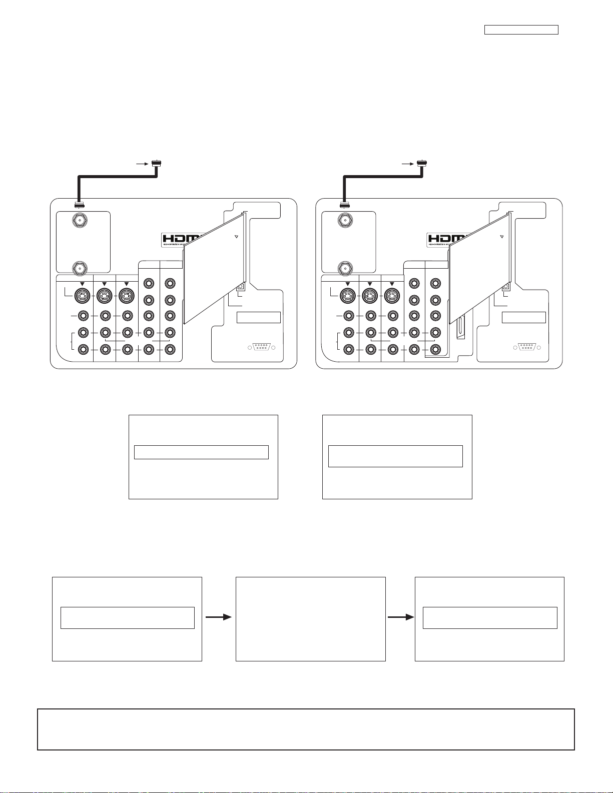
II. FEATURES AND FUNCTIONS
CableCARD is installed CableCARD
is not installed
OR
In order to start cable service
for this device, please contact
your cable provider
CableCARD(tm): 123-456-789-1
Host: 123-456-789-1
Data: 123-456-789-1
UnitAddress: 123-456-789-1
Acquiring Data.
Please wait.
Press EXIT to return
Not an Authorized Channel
Digital Cable
Apparatus Claims of U.S. Patent Nos.
4,631,603; 4,577,216; 4,819,098;
4,907,093; and 6,381,747 licensed
for limited viewing uses only.
12345
9876
RS232C
Digital Cable
Apparatus Claims of U.S. Patent Nos.
4,631,603; 4,577,216; 4,819,098;
4,907,093; and 6,381,747 licensed
for limited viewing uses only.
12345
9876
RS232C
ANT A
S-VIDEO
R
L
VIDEO
AUDIO
(MONO)
(MONO) (MONO) (MONO)
P
R
P
B
Y/
VIDEO
Y/
VIDEO
P
R
P
B
MONITOR OUT INPUT 4 INPUT 3
INPUT 2 INPUT 1
HDMI 1
ANT B
Upgrade Card
CableCARD
(Top of card faces right)
OPTICAL OUT
Digital Audio
AUDIO
TO HI-FI
TV AS CENTER
ANT A
S-VIDEO
R
L
VIDEO
AUDIO
(MONO)
(MONO) (MONO) (MONO)
P
R
P
B
Y/
VIDEO
Y/
VIDEO
P
R
P
B
MONITOR OUT INPUT 4 INPUT 3
INPUT 2 INPUT 1
HDMI 1
ANT B
Upgrade Card
CableCARD
(Top of card faces right)
OPTICAL OUT
Digital Audio
AUDIO
TO HI-FI
TV AS CENTER
HDMI 2
INSERT THIS END
CableCARD
INSERT THIS END
CableCARD
LC48/B-LC47/B/K
2.0 REAR PANEL JACKS (CONT.)
k CableCARD Slot
This slot is for the CableCARD that will be provided by your local cable operator to gain access to chosen cable channels. The
CableCARD will allow you to tune digital and high definition cable channels. Please call your local cable operator if this service is
available before requesting a CableCARD (also known as Point of Deployment (POD) module).
Connect a coaxial cable to ANT A terminal of the Rear Panel Jacks.
Insert the CableCARD into the slot (Top of card should be facing right as shown).
Models: 42V710/50V715/60V715
Models: 50VS810/60VS810
If the CableCARD is properly installed or not installed, the TV will display the following respective screens.
After the CableCARD is installed, wait until the second screen below appears. The third screen below will appear if a channel is not
authorized for viewing. Press the EXIT button to exit the second screen.
Please take note of all information on the screen (you will provide this information to your cable operator). Call your cable operator
and give them the information from the card to start your cable service.
NOTES: 1. A digital cable subscription is required.
2. Antenna B will not be available when CableCARD is inserted.
3. Do not insert a PCMCIA card into the CableCARD slot.
19
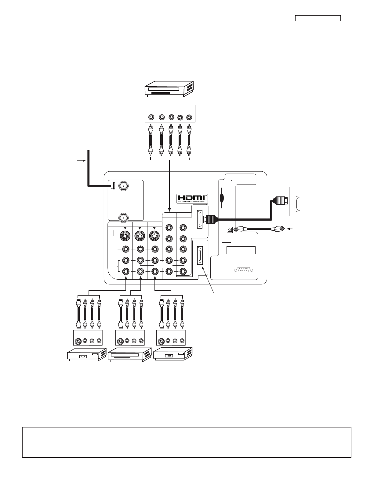
VCR #2
Outside antenna or
digital cable
Laserdisc player, VCR,
camcorder, etc.
VCR #1
DVD Player
OUTPUT
YP
B/CBPR/CR
L R
To an amplifier/receiver
with optical input capability.
External Digital
Component with
HDMI output
capability
Apparatus Claims of U.S. Patent Nos.
4,631,603; 4,577,216; 4,819,098;
4,907,093; and 6,381,747 licensed
for limited viewing uses only.
AUDIO
TO HI-FI
12345
9876
HDMI 2
Extra HDMI (Input 2) only
for 50VS810 and 60VS810
INPUT
S-VIDEO
VLR
OUTPUT
S-VIDEO
VLR
OUTPUT
S-VIDEO
VLR
ANT A
S-VIDEO
R
L
VIDEO
AUDIO
(MONO)
(MONO) (MONO) (MONO)
P
R
P
B
Y/
VIDEO
Y/
VIDEO
P
R
P
B
MONITOR OUT INPUT 4 INPUT 3
INPUT 2 INPUT 1
HDMI 1
RS232C
ANT B
Upgrade Card
CableCARD
(Top of card faces right)
OPTICAL OUT
Digital Audio
HDMI
OUT
TV AS CENTER
II. FEATURES AND FUNCTIONS
2.0 REAR PANEL JACKS (CONT.)
LC48/B-LC47/B/K
NOTES: 1.
Connect only 1 component to each input jack.
2. Follow connections that pertain to your personal entertainment system.
3. Inputs 1 and 2 can accomodate Composite and Component video signals.
4. Cables are not included with the purchase of this TV, except when noted as “provided”.
20

LC48/B-LC47/B/K
II. FEATURES AND FUNCTIONS
2.0 REAR PANEL JACKS (CONT.)
• S-VIDEO, HDMI and component connections are provided for high performance laserdisc players, VCRs etc. that have this
feature. Use these connections in place of the standard video connection if your device has this feature.
• If your device has only one audio output (mono sound), connect it to the left audio jack on the television.
• Refer to the operating guide of your other electronic equipment for additional information on connecting your hook-up cables.
• A single VCR can be used for VCR #1 and VCR #2, but note that a VCR cannot record its own video or line output. Refer to your
VCR operating guide for more information on line input-output connections.
• You may use VIDEO or S-VIDEO inputs to connect to Input 3, Input 4 or Input 5, but only one of these may be used at a time.
• Connect only 1 component (VCR, DVD player, camcorder, etc.) to each input jack.
• COMPONENT: Y-PBPR (Input 1 &2) connections are provided for high performance components, such as DVD players and settop-boxes. Use these connections in place of the standard video connection if your device has this feature.
• Your component outputs may be labeled Y, B-Y, and R-Y. In this case, connect the components B-Y output to the TV’s PBinput
and the components R-Y output to the TV’s PRinput.
• Your component outputs may be labeled Y-CBCR. In this case, connect the components CBoutput to the TV’s PBinput and
the components CRoutput to the TV’s PRinput.
• It may be necessary to adjust TINT to obtain optimum picture quality when using the Y-PBPRinputs.
• To ensure no copyright infringement, the MONITOR OUT output may be abnormal, when using the
• When using HDMI or DVI input from a Set-Top-Box, it is recommended to use a 1080i or 720p input signal.
Y- PBP
R
jacks.
21

II. FEATURES AND FUNCTIONS
LC48/B-LC47/B/K
3.0 LAMP REPLACEMENT
Lamp Lif
The lamp life may vary based on usage of the LCD Rear PTV. Turning on and off frequently may
shorten the life of the lamp.
Lamp Replacement
After extended use, if the TV picture turns dark, the color looks unusual or LAMP INDICATOR light
turns on, then it is time to replace the lamp with a new lamp.
WARNING:
• Do not open lamp compartment or attempt to remove lamp assembly unless the lamp assembly is being replaced.
• Unplug the product’s power cord from the AC outlet before attempting to replace the lamp assembly.
• If the lamp is in use when failure occurs or if the lamp has exploded, wait at least 30-45 minutes for the lamp to
• Broken lamp pieces can cause injury. Handle with gloves to avoid cuts.
• Do not place any foreign objects inside the lamp compartment.
• When installing a new lamp, follow handling instruction included with the new lamp. Do not touch glass surface of
• This product contains lead and a lamp that contains mercury. Dispose of this product and its lamp in accordance
CAUTION!
e
The lamp gets very hot! The lamp may explode if improperly handled. To avoid injury, please observe the following precautions.
cool before opening the lamp compartment or touching the lamp assembly or any broken pieces.
new lamp.
with applicable environmental laws. For lamp recycling and disposal information, go to www.lamprecycle.org. For
product recycling and disposal information, contact your local government agency or the Electronic Industries
Alliance at www.eiae.org (in the US) or the Electronic Product Stewardship Canada at www.epsc.ca (in Canada).
For more information, call “1-800-HITACHI.”
A ”LAMP” indicator will light when lamp becomes hot. Unplug product’s power cord from the AC outlet and allow
lamp to cool for at least 30-45 minutes. If “LAMP” indicator is still lit, please contact your authorized service
center.
NOTES:
• Contact your Hitachi dealer for a new lamp unit. Using other lamps may cause damage to the TV
Set.
LAMP TYPE: LCD PTV Model No.:
LM500 42V710/715, 50V710/715, 60V710/715
LM700 50/60/70VS810
• When replacing the lamp, let it cool down completely, for approximately 30 to 45 minutes after the
power has been switched off and A.C. cord has been unplugged.
• Do not touch the glass of the new lamp or make it dirty which can shorten the life of the lamp and
reduce the picture quality.
• Keep the lamp out of the reach of children and away from flammable materials.
• Do not pour water onto the removed lamp or put any object inside the lamp.
• Once the lamp is removed, do not put flammable materials and metal objects inside the lamp
receptacle on the TV set. Do not touch the receptacle.
• Install the new lamp securely, otherwise the picture may become dark or it may cause severe overheating.
• Install the lamp cover correctly, otherwise power will not come on.
• This product contains lead and a lamp that contains mercury. Dispose of this product and its lamp
in accordance with applicable environmental laws. For lamp recycling and disposal information, go
to www.lamprecycle.org. For product recycling and disposal information, contact your local government agency or the Electronic Industries Alliance at www.eiae.org (in the US) or the Electronic
Product Stewardship Canada at www.epsc.ca (in Canada).
For more information, call “1-800-HITACHI.”
BACK TO ADJUSTMENTS
22
LC48/B-LC47/B/K
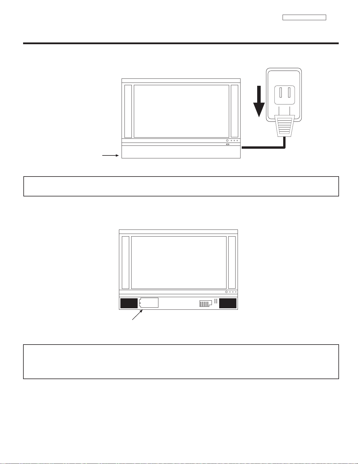
120V
FRONT COVER
LAMP COMPARTMENT
3.0 LAMP REPLACEMENT
1. Turn off the main power switch and unplug the power cord. Wait at least 30 minutes to allow the lamp to cool down before
replacing it.
NOTE:
THE LAMP IS VERY HOT AND MAY CAUSE FIRE OR SEVERE BURNS. WAIT AT LEAST 30~45
MINUTES TO ALLOW THE LAMP TO COOL BEFORE PROCEEDING WITH LAMP REMOVAL.
2. Remove the front cover from the TV set. This is held by a snap on. Pull the front cover outwards until the quick snap on
disengages.
NOTE: This product contains lead and a lamp that contains mercury. Dispose of this product and its lamp in accordance with
applicable environmental laws. For lamp recycling and disposal information, go to www.lamprecycle.org. For product
recycling and disposal information, contact your local government agency or the Electronic Industries Alliance at
www.eiae.org (in the US) or the Electronic Product Stewardship Canada at www.epsc.ca (in Canada).
For more information, call “1-800-HITACHI.”
23
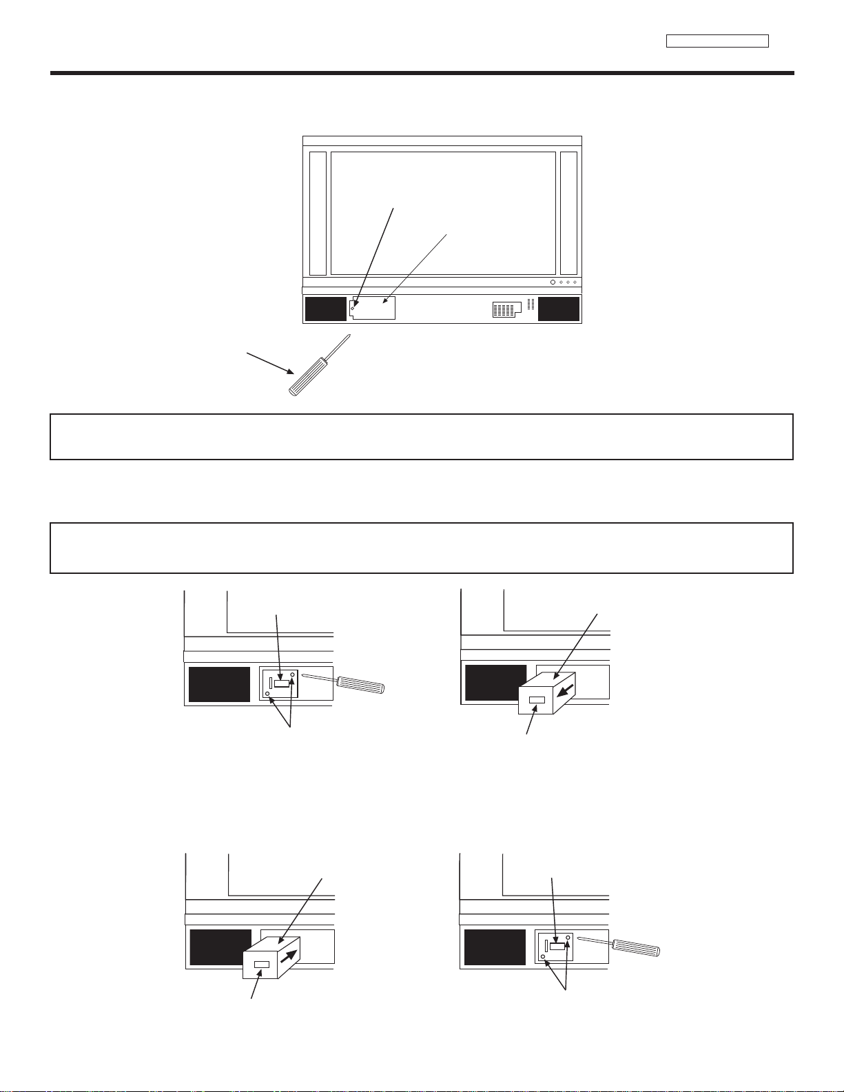
LC48/B-LC47/B/K
SCREW
LAMP COVER
PHILLIP HEAD
SCREW DRIVER
HANDLE
REMOVE SCREWS
HANDLE
LAMP UNIT
HANDLE
LAMP UNIT
TIGHTEN THE SCREWS
HANDLE
3.0 LAMP REPLACEMENT
3. Remove the screw securing the lamp cover with a Phillips head screw driver as shown. Remove the lamp cover.
NOTE:
THE LAMP IS VERY HOT AND MAY CAUSE FIRE OR SEVERE BURNS. WAIT AT LEAST 30~45
MINUTES TO ALLOW THE LAMP TO COOL BEFORE PROCEEDING WITH LAMP REMOVAL.
4. Remove the two screws that hold the lamp in place. Remove the lamp unit by holding the lamp handle, then pulling outwards.
Exercise caution when removing the lamp unit to avoid injury to your fingers.
NOTE:
DO NOT PUT YOUR HAND IN THE LAMP STORAGE AREA AFTER THE LAMP UNIT IS
REMOVED, YOU MAY GET BURNED.
5. Replace with the new lamp.
Place the removed lamp into the empty box of the replacement lamp. Do not touch the front glass of the new lamp or its
receptacle. This may shorten the life of the lamp and reduce the picture quality.
• Push the lamp unit back to its original position.
• Tighten the screws firmly on the lamp unit. If they are loose, the TV may not operate correctly.
24
II. FEATURES AND FUNCTIONS
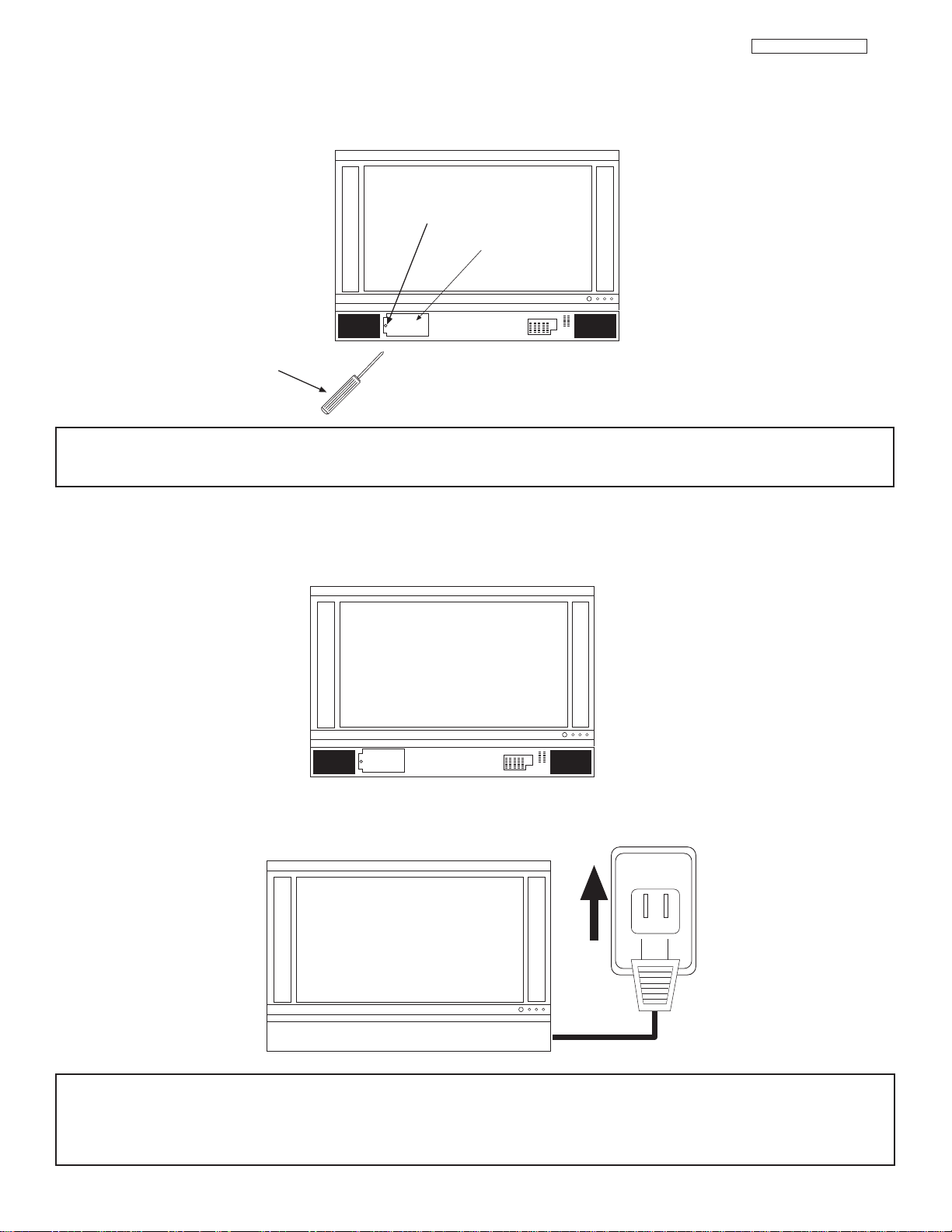
SCREW
LAMP COVER
PHILLIP HEAD
SCREW DRIVER
120V
LC48/B-LC47/B/K
3.0 LAMP REPLACEMENT (CONT.)
6. Without installing the lamp cover, the power will be off and the Lamp Indicator will flash. Be sure to install the lamp cover by reengaging the two clips and tighten the screws before turning the power on, otherwise it may cause unusual colors.
NOTE: IF POWER IS CONNECTED BEFORE THE LAMP COVER IS INSTALLED, THE POWER WILL
BE OFF AND THE LAMP INDICATOR WILL FLASH.
7. Install the front cover as shown below. Put the front cover back in and align the snap on quick connect then push inwards holding
the left and right side of the front cover until you hear a snap. Push the other snap on gently to make a good fit.
8. Plug power cord into AC outlet and turn on the main power switch.
NOTE: This product contains lead and a lamp that contains mercury. Dispose of this product and its lamp in accordance with
applicable environmental laws. For lamp recycling and disposal information, go to www.lamprecycle.org. For product
recycling and disposal information, contact your local government agency or the Electronic Industries Alliance at
www.eiae.org (in the US) or the Electronic Product Stewardship Canada at www.epsc.ca (in Canada).
For more information, call “1-800-HITACHI.”
25

II. FEATURES AND FUNCTIONS
GUIDE
Locks
Chan. Manager
Aspect
Audio
Video
Move
SEL
Sel
Timers
Setup
4.0 ON-SCREEN-DISPLAY FEATURES
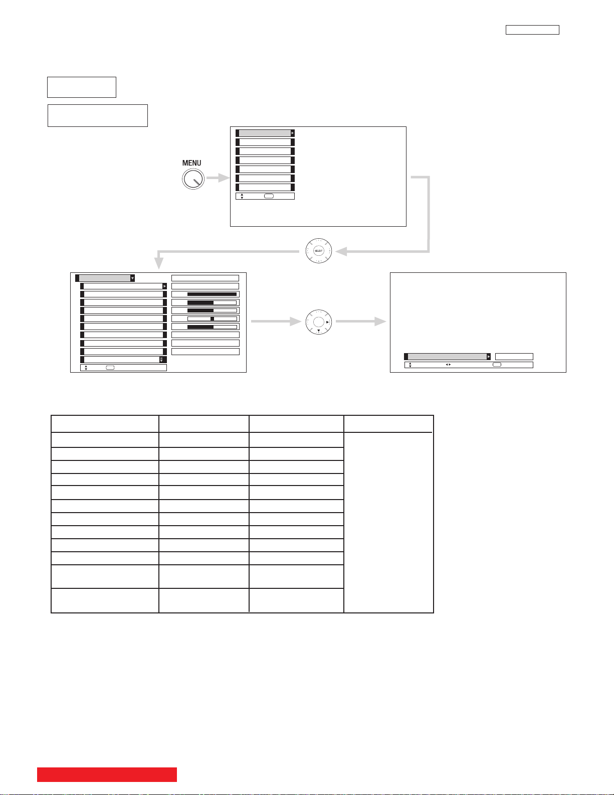
1. Press MENU on the remote control to display the different features on your HITACHI LCD TV.
2. Press the CURSOR PAD to highlight a different feature.
3. Press EXIT on the remote control to quickly exit from a menu.
LC37
This part of the screen shows
which selections are available.
This part of the screen shows
which Remote Control buttons
to use.
BACK TO ADJUSTMENTS
26
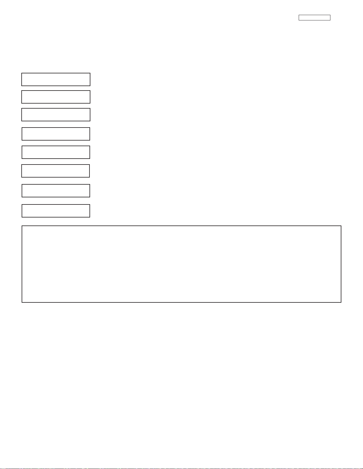
Video
Audio
Aspect
II. FEATURES AND FUNCTIONS
4.0 ON-SCREEN-DISPLAY FEATURES
Picture Mode Select between the two picture modes; Day and Night.
Contrast Adjust contrast.
Brightness Adjust brightness.
Color Adjust color.
Tint Adjust tint.
Sharpness Adjust sharpness.
Color Temperature Set this to High for less intense color with more blue, set to Medium
Black Enhancement Adjust shadow detail in dark screens.
Contrast Mode Choose Automatic Contrast setttings.
Reset Video Settings Choose the Reset Video settings.
Color Management Adjust and balance individual colors to make either deeper or more
Color Decoding Adjust the percentage of Red, Green and Color according to preference.
Auto Color
Noise Reduction Reduces conspicuous noise in the picture.
Auto Movie Mode Turn ON/OFF the 3:2 Pulldown detection feature.
Treble Adjust the treble.
Bass Adjust the bass.
Balance Adjust the balance.
SRS Select SRS settings (Off, Wide, Normal)
BBE Select BBE settings (Off, Soft, Hard)
Audio Source Select between three Audio Sources.
Internal Speakers Select internal or external speakers.
Auto Noise Cancel Eliminates the noise between stations.
Perfect Volume Adjust volume in fixed setting.
Loudness Adjust Loudness.
Language Select Language options if available.
Digital Output Select Optical Output options.
DRC Select Dynamic Range Compression to ON or OFF.
LC48/B-LC47/B/K
for natural color, set to Standard for standard colors or Black and
White for more reddish color.
pure according to preference.
The AUTO COLOR function automatically monitors and adjusts the
color to maintain constant color levels even after a program or channel
changes. It also maintains natural flesh tones while preserving fidelity
of background colors.
4:3 Standard
4:3 Expanded
4:3 Zoom 1 Choose the picture format aspect ratio.
4:3 Zoom 2
16:9 Standard
16:9 Zoom
NOTE: The Language, Digital Output, and the Dynamic Range Compression feature of the Audio OSD are only available for
Digital channels.
27
II. FEATURES AND FUNCTIONS
Channel
Manager
Locks
Setup
Timers
4.0 ON-SCREEN-DISPLAY FEATURES
Set the Antenna Set Antenna settings.
Auto Channel Scan Set Auto Channel Scan.
Signal Meter Access Signal Meter.
Channel List Set Channel List.
Change Access Code Change Lock access code.
Engage Lock Choose to lock channel, video input, and/or front panel.
TV Time Lock Set specific time to Lock TV.
Movie Ratings Block various types of movies and video types based on motion
TV Ratings Block various types of movies and television programming based on a
Canadian Ratings (ENG) Block various types of movies and television programming based on
Canadian Ratings (FRN) Block various types of movies and television programming based on
Set the Clock Set Clock Settings.
Set Sleep Timer Set Sleep Timer intervals (30 min. intervals, 00:30-3:00).
Set Day/Night Timer Set Day/Night picture mode settings.
Set Event Timer Set viewing reservation for TV programs.
Set Auto Power Off Set TV to turn off automatically when a video signal is not detected for 15
LC48/B-LC47/B/K
picture ratings.
parental guide ratings.
the Canadian ratings system.
the Canadian French ratings system.
minutes.
Menu Preference Choose English, French, or Spanish text.
Screen Saver Set the Screen Saver.
Set The Inputs Label Video Inputs , VCR, DVD, etc.
Set Virtual HD Select between 1080i and 540p signal.
Set Black Side Panel Set the gray side bars on/off when watching 4:3 signals in standard mode.
Set Closed Captions Feature to display dialogue/text.
Set Monitor Out Set Monitor Out source.
CableCARD Info Select to access CableCARD information.
Set AV Control Select to set RS232C feature.
Upgrades Select to upgrade TV software.
Quick Start Up Select the TV Quick Start Up options.
NOTES: 1. The Signal Meter feature of the Channel Manager OSD is only available for ATSC signals.
2. The CableCARD information feature of the Setup OSD is only available when a CableCARD from your cable
operator is installed in the rear panel of the TV.
28
II. FEATURES AND FUNCTIONS
Color
Brightness
Contrast
Picture Mode
Video
Move
SEL
Select
Color Temperature
Sharpness
Tint
Edge Enhancement
Black Enhancement
100%
50%
50%
50%
High
Locks
Chan. Manager
Aspect
Audio
Video
Move
SEL
Sel
SEL
Select
Day Night
Timers
Reset Video Settings
ANT A/B
High
High
Picture Mode
Day Night
Return
Next/Prev
Setup
Video
Contrast 100% 70%
Brightness 50% 55%
Color 50% 50%
Tint 50% 50%
Sharpness 50% 40%
Color Temperature High Standard
Black Enhancement Middle Low
Edge Enhancement High Low
Auto Color Off Off
Noise Reduction Off Off
Color Management Off Off
(Set User Colors)
Auto Movie Mode Off Off
(TV/Cinema Detection)
Function Day Night Reset
Reset the video
menu settings on
current input to the
Day or Night
conditions depending
on the selected
VIDEO mode.
4.1 VIDEO SETTING
Select VIDEO to adjust picture settings and improve picture quality. You can independently customize each of the
Video Inputs to your preference to increase viewing performance and pleasure depending upon the video program
being viewed. If RESET is selected, only the selected input will reset to initial conditions.
LC37/LC37F
Picture Mode
Use this function to choose from automatic picture settings to optimize your TV’s performance.
Use CURSOR PAD F or E to highlight and select Picture Mode settings.
Press EXIT to quit menu or select PICTURE MODE to return to previous menu.
BACK TO ADJUSTMENTS
29
II. FEATURES AND FUNCTIONS
4.1 VIDEO SETTING
LC37/LC37F
Use the CURSOR PAD
Press the CURSOR PAD
Press MENU to return to main menu or select PICTURE MODE to return to previous menu.
Press EXIT to quit menu.
Contrast
Brightness
Color
Tint
Sharpness
Color Temperature
Black Enhancement
Edge Enhancement
G or H to highlight the function to be adjusted.
F or E to adjust the function. Press the SELECT button to select the function settings.
Use this function to change the contrast between black and white levels in the picture.
Use this function to adjust overall picture brightness.
Use this function to adjust the level of color in the picture.
Use this function to adjust flesh tones so they appear natural.
Use this function to adjust the amount of fine detail in the picture. Sharpness function will be disabled
when Noise Reduction is on.
Set this to High for cooler color with more blue, set to Medium for more natural color, set to Standard for
accurate color or set to Black/White for more reddish color.
Use this function to enhance the shadow detail in dark scenes using the settings off, low, middle and high.
Use this function to automatically enhance the edges between light and dark areas using the settings Off,
Low, Middle and High.
NOTES: 1. If CONTRAST is selected, you are adjusting CONTRAST. The additional menu items BRIGHTNESS, COLOR, TINT,
and SHARPNESS can be selected and adjusted in the same manner.
2. Contrast will decrease automatically if stationary images such as digital photos are left on the screen for more than 3
minutes.
3. It may be necessary to adjust TINT to obtain optimum picture quality when using the COMPONENT VIDEO Y-PBP
input jacks.
4. If you are using the COMPONENT VIDEO input jacks (Y-PBPR) and notice that the TINT and COLOR are abnormal,
check to make sure that the VIDEO-Color System is set properly.
5. ANT A and B share a Video setting. Also, each of the video inputs have their own independent settings.
6. If CONTRAST is set to minimum level, the On-Screen Display (OSD) will be difficult to see.
R
30
 Loading...