

Hitachi 50V500, 60V500A Schematic

SAFETY PRECAUTIONS......................................................................................................2
PRODUCT SAFETY NOTICE................................................................................................3
SERVICING PRECAUTIONS................................................................................................4
AGENCY REGULATORY INFORMATION ............................................................................8
TABLE OF CONTENTS ........................................................................................................9
SPECIFICATIONS................................................................................................................11
FEA TURES AND FUNCTIONS............................................................................................22
PWB ADJUSTMENTS ........................................................................................................49
TROUBLESHOOTING FLOW CHARTS..............................................................................95
DC VOLTAGE ......................................................................................................................96
WAVEFORMS ..................................................................................................................108
REPLACEMENT PARTS LIST ..........................................................................................114
EXPLODED VIEW ............................................................................................................138
PRINTED CIRCUIT BOARDS ..........................................................................................148
CONNECTION DIAGRAM ................................................................................................160
BLOCK DIAGRAM ............................................................................................................161
BASIC CIRCUIT SCHEMATIC DIAGRAM ........................................................................162
FINAL WIRING DIAGRAM ................................................................................................175
MAJOR ICS & UNITS........................................................................................................179
PA
50V500/LC37
60V500A/LC37F
No. 0178
NTSC
LC37 Chassis
LC37F Chassis
R/C: CLU-5729TSI
CAUTION: Before servicing this chassis, it is important that the service technician read the
“Product Safety Notices” in this service manual.
SAFETY NOTICE
USE ISOLATION TRANSFORMER WHEN SERVICING
Components having special safety characteristics are identified by a on the parts list in this
Service Data and its supplements and bulletins. Before servicing the chassis, it is important that
the service technician read and follow the “Safety Precautions” and “Product Safety Notices” in
this Service Manual.
SPECIFICATIONS AND PARTS ARE SUBJECT TO CHANGE FOR IMPROVEMENT
LCD REAR PROJECTION TELEVISION
JUNE 2003 HHEA-MANUFACTURING DIVISION
!
OPTICAL ENGINE REMOVAL PROCEDURE ..................................................................181
NOTE: This product is to be serviced at board level.
Updated 05/27/04
Updated 02/25/04
TO GO TO A CHAPTER, CLICK ON ITS HEADING BELOW
Updated 01/14/04
Version 0178.04

2
LC37/LC37F
NOTICE: Comply with all cautions and safety-related notes
located on or inside the cabinet and on the chassis or optic unit.
WARNING: Since the chassis of this receiver is connected to
one side of the AC power supply during operation, whenever the
receiver is plugged in service should not be attempted by anyone unfamiliar with the precautions necessary when working on
this type of receiver.
The following precautions should be observed:
1. Do not install, remove, or handle the optic unit in any manner
unless shatterproof goggles are worn. People not so equipped
should be kept away from the optic unit while handling.
2. When service is required, an isolation transformer should be
inserted between power line and the receiver before any service is performed on a “HOT” chassis receiver.
3. When replacing a chassis in the receiver, all the protective
devices must be put back in place, such as barriers, nonmetallic knobs, adjustment and compartment cover-shields, isolation
resistors, capacitors, etc.
4. When service is required, observe the original lead dress.
5. Always use the manufacturer’s replacement components.
Critical components as indicated on the circuit diagram should
not be replaced by another manufacturer’s. Furthermore, where
a short circuit has occurred, replace those components that
indicate evidence of overheating.
6. Before returning a serviced receiver to the customer, the service technician must thoroughly test the unit to be certain that it
is completely safe to operate without danger of electrical shock,
and be sure that no protective device built into the receiver by
the manufacturer has become defective, or inadvertently
defeated during servicing.
Therefore, the following checks should be performed for the continued protection of the customer and service technician.
Leakage Current Cold Check
With the AC plug removed from the 120V AC 60Hz source, place
a jumper across the two plug prongs. Using an insulation tester
(DC500V), connect one lead to the jumpered AC plug and touch
the other lead to each exposed metal part (antennas, screwheads,
metal overlays, control shafts, etc.), particularly any exposed
metal part having a return path to the chassis should have a minimum resistor reading of 2.4M and a maximum resistor reading
of 5.2M. Any resistance value below or above this range indicates an abnormality which requires corrective action. An exposed
metal part having a return path to the chassis will indicate an open
circuit.
AC LEAKAGE TEST
ANY MEASUREMENTS NOT WITHIN THE LIMITS OUTLINED
ABOVE ARE INDICATIVE OF A POTENTIAL SHOCK HAZARD
AND MUST BE CORRECTED BEFORE RETURNING THE
RECEIVER TO THE CUSTOMER.
SAFETY PRECAUTIONS
Leakage Current Hot Check
Plug the AC line cord directly into a 120V AC 60Hz outlet (do not use
an isolated transformer for this check). Turn the AC power ON. Using
a Leakage Current Tester (Simpson’s Model 228 or equivalent),
measure for current from all exposed metal parts of the cabinet
(antennas, screwheads, overlays, control shafts, etc.) particularly
any exposed metal
part having a return path to the chassis or to a
known earth ground (water pipe, conduit, etc.). Any current measured must not exceed 0.5 MIU.
TABLE OF CONTENTS
(READING
SHOULD NOT
BE ABOVE
0.5 MIU)
(READING
SHOULD NOT
BE ABOVE
0.5 mA)
-
+
EARTH
GROUND
DEVICE
UNDER
TEST
2-WIRE CORD
ALSO TEST WITH
PLUG REVERSED (USING
AC ADAPTER PLUS
AS REQUIRED)
TEST ALL
EXPOSED
METAL
SURFACES
LEAKAGE
CURRENT
TESTER

3
LC37/LC37F
Many electrical and mechanical parts in HITACHI television
receivers have special safety-related characteristics. These are
often not evident from visual inspection nor can the protection
afforded by them necessarily be obtained by using replacement
components rated for higher voltage, wattage, etc. Replacement
parts which have these special safety characteristics are identified
in this Service Manual.
Electrical components having such features are identified with an
! mark in the schematics and parts list in this Service Manual.
The use of a substitute replacement component which does not
have the same safety characteristics as the HITACHI-recommended replacement component, shown in the parts list in this
Service Manual, may create shock, fire, or other hazards.
Production safety is continuously under review and new instructions are issued from time to time. For the latest information,
always consult the current HITACHI Service Manual. A subscription to, or additional copies of HITACHI Service Manuals may be
obtained at a nominal charge from HITACHI Sales Corporation.
Ultraviolet Radiation
OPTIC UNIT: The primary source of Ultraviolet Radiation in this
receiver is the optic unit. The optic unit utilized in this chassis is
specially constructed to limit Ultraviolet Radiation emissions. For
continued Ultraviolet Radiation protection, the replacement optic
unit must be the same type as the original HITACHI-approved
type.
Service Personnel - WARNING
Eye damage may result from directly viewing the light produced by
the lamp used in this product. Always turn off lamp before opening optic unit. Ultraviolet radiation eye protection required during
servicing.
When troubleshooting and making test measurements in a receiver with an excessive high voltage problem, avoid being unnecessarily close to the optic unit and the high voltage component.
Do not operate the chassis longer than is necessary to locate the
cause of excessive voltage.
This Service Manual is intended for qualified service technicians; it is not meant for the casual do-it-yourselfer. Qualified
technicians have the necessary test equipment and tools, and
have been trained to properly and safely repair complex products such as those covered by this manual. Improperly performed repairs can adversely affect the safety and reliability of
the product and may void warranty. Consumers should not risk
trying to do the necessary repairs and should refer to a qualified service technician.
WARNING
Lead in solder used in this product is listed by the California Health
and Welfare agency as a known reproductive toxicant which may
cause birth defects or other reproductive harm (California Health
and Safety Code, Section 25249.5).
When servicing or handling circuit boards and other components which contain lead in solder, avoid unprotected skin
contact with solder. Also, when soldering do not inhale any
smoke or fumes produced.
SAFETY NOTICE
USE ISOLATION TRANSFORMER
WHEN SERVICING
Components having special safety characteristics identified by
!
on the parts list in this service manual and its
supplements and bulletins. Before servicing this product, it
is important that the service technician read and follow the
“Safety Precautions” and the “Product Safety Notices” in
this Service Manual.
For continued ultraviolet protection, replace optic unit with
original type or HITACHI equivalent type.
POWER SOURCE
This television receiver is designed to operate on 120
Volts/60Hz, AC house current. Insert the power cord into
a 120 Volts/60Hz outlet.
NEVER CONNECT THE TV TO OTHER THAN THE
SPECIFIED VOLTAGE OR TO DIRECT CURRENT.
CAUTION!
The following symbol near the fuse indicates fast operating fuse (to be replaced). Fuse ratings appear within the
symbol.
Example:
The rating of fuse F901 is 6.0A-125V.
Replace with the same type of fuse for continued protection against fire.
The lamp in this product contains Mercury.
Dispose of properly in accordance with applicable
environmental laws. For Recycling and Disposal
information, contact your respective governmental agencies or the Electronic Industries Alliance
at www.eiae.org (in the U.S.) or Electronic
Product Stewardship Canada at www.epsc.ca (in
Canada).
PRODUCT SAFETY NOTICE
125V
6A
F901
NOTE:
TABLE OF CONTENTS

4
LC37/LC37F
CAUTION: Before servicing instruments covered by this service
data and its supplements and addenda, read and follow the SAFETY PRECAUTIONS on page 2 of this publication.
NOTE: If unforseen circumstances create conflict between the following SERVICING PRECAUTIONS and any of the SAFETY PRECAUTIONS on page 2 of this publication, always follow the SAFETY
PRECAUTIONS.
Remember: Safety First.
General Servicing Guidelines
1. Always unplug the instrument AC power cord from the AC power
source before:
a. Removing or reinstalling any component, circuit board,
module, or any other instrument assembly.
b. Disconnecting or reconnecting any instrument electrical
plug or other electrical connection.
c. Connecting a test substitute in parallel with an electrolyt-
ic capacitor in the instrument.
CAUTION: A wrong part substitution or incorrect
polarity installation of electrolytic
capacitors may result in an
explosion hazard.
2. Do not spray chemicals on or near this instrument or any of its
assemblies.
3. Unless specified otherwise in these service data, clean electrical contacts by applying the following mixture to the contacts
with a pipe cleaner, cotton-tipped stick or comparable nonabrasive applicator: 10% (by volume) Acetone and 90% (by volume)
ispropyle alchohol (90%-99% strength).
CAUTION: This is a flammable mixture. Unless specified
otherwise in these service data, lubrication of
contacts is not required.
4. Do not defeat any plug/socket B+ voltage interlocks with which
instruments covered by this service data might be equipped.
5. Do not apply AC power to this instrument and/or any of its electrical assemblies unless all solid-state device heat-sinks are correctly installed.
6. Always connect the test instrument ground lead to the appropriate instrument chassis ground before connecting the test instrument positive lead. Always remove the test instrument ground
lead last.
7. Use with this instrument only the test fixtures specified in this
service data.
CAUTION: Do not connect the test fixture ground strap to
any heatsink in this instrument.
Electrostatically Sensitive (ES) Devices
Some semiconductor (solid state) devices can be damaged easily
by static electricity. Such components commonly are called
Electrostatically Sensitive (ES) Devices. Examples of typical ES
devices are integrated circuits and some field-effect transistors and
semiconductor “chip” components. The following techniques should
be used to help reduce the incidence of component damage caused
by static electricity.
1. Immediately before handling any semiconductor component or
semiconductor-equipped assembly, drain off any electrostatic
charge on your body by touching a known earth ground.
Alternatively, obtain and wear a commercially available discharging wrist strap device, which should be removed for potential shock reasons prior to applying power to the unit under test.
2. After removing an electrical assembly equipped with ES
devices, place the assembly on a conductive surface such as
aluminum foil, to prevent electrostatic charge build-up or exposure of the assembly.
3. Use only a grounded-tip soldering iron to solder or desolder ES
devices.
4. Use only an anti-static type solder removal device. Some solder removal devices not classified as “anti-static” can generate
electrical charges sufficient to damage ES device.
5. Do not use freon-propelled chemicals. These can generate
electrical charges sufficient to damage ES devices.
6. Do not remove a replacement ES device from its protective
package until immediately before you are ready to install it.
(Most replacement ES devices are packaged with leads electrically shorted together by conductive foam, aluminum foil or
comparable conductive material.)
7. Immediately before removing the protective material from the
leads of a replacement ES device, touch the protective material
to the chassis or circuit assembly into which the device will be
installed.
CAUTION: Be sure no power is applied to the chassis or
circuit, and observe all other safety precautions.
8. Minimize bodily motions when handling unpackaged replacement ES devices. (Otherwise harmless motion such as the
brushing together of your clothes fabric or the lifting of your foot
from a carpeted floor can generate static electricity sufficient to
damage an ES device.)
SERVICING PRECAUTIONS
TABLE OF CONTENTS
5
LC37/LC37F
General Soldering Guidelines
1. Use a grounded-tip, low-wattage soldering iron and appropriate
tip size and shape that will maintain tip temperature within the
range 500°F to 600°F.
2. Use an appropriate gauge of resin-core solder composed of 60
parts tin/40 parts lead.
3. Keep the soldering iron tip clean and well-tinned.
4. Thoroughly clean the surfaces to be soldered. Use a small wirebristle (0.5 inch or 1.25 cm) brush with a metal handle. Do not
use freon-propelled spray-on cleaners.
5. Use the following desoldering technique.
a. Allow the soldering iron tip to reach normal temperature
(500°F to 600°F).
b. Heat the component lead until the solder melts. Quickly
draw away the melted solder with an anti-static, suctiontype solder removal device or with solder braid.
CAUTION: Work quickly to avoid overheating the circuit
board printed foil.
6. Use the following soldering technique.
a. Allow the sodering iron tip to reach normal temperature
(500°F to 600°F).
b. First, hold the soldering iron tip and solder strand against
the component lead until the solder melts.
c. Quickly move the soldering iron tip to the junction of the
component lead and the printed circuit foil, and hold it
there only until the solder flows onto and around both the
component lead and the foil.
CAUTION: Work quickly to avoid overheating the circuit
board printed foil or components.
d. Closely inspect the solder area and remove any excess
or splashed solder with a small wire-bristle brush.
IC Removal/Replacement
Some Hitachi unitized chassis circuit boards have slotted holes
(oblong) through which the IC leads are inserted and then bent flat
against the circuit foil. When holes are the slotted type, the following technique should be used to remove and replace the IC. When
working with boards using the familiar round hole, use the standard
technique as outlined in paragraphs 5 and 6 above.
Removal
1. Desolder and straighten each IC lead in one operation by gently prying up on the lead with the soldering iron tip as the solder
melts.
2. Draw away the melted solder with an anti-static suction-type sol
der removal device (or with solder braid) before removing the
IC.
Replacement
1. Carefully insert the replacement IC in the circuit board.
2. Carefully bend each IC lead against the circuit foil pad and
solder it.
3. Clean the soldered areas with a small wire-bristle brush. (It is
not necessary to reapply acrylic coating to areas.)
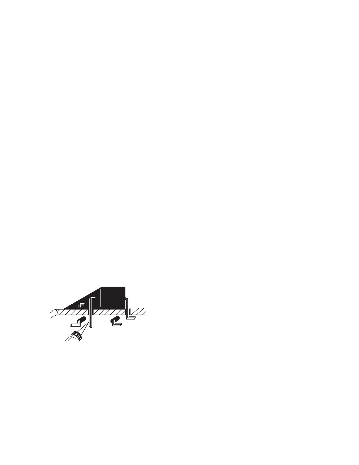
“Small-signal” Discrete Transistor Removal/Replacement
1. Remove the defective transistor by clipping its leads as close as
possible to the component body.
2. Bend into a “U” shape the end of each of three leads remaining on the circuit board.
3. Bend into a “U” shape the replacement transistor leads.
4. Connect to replacement transistor leads to the corresponding
leads extending from the circuit board and crimp the “U” with
long nose pliers to insure metal to metal contact, then solder
each connection.
Power Output Transistor Devices Removal/Replacement
1. Heat and remove all solder from around the transistor leads.
2. Remove the heatsink mounting screw (if so equipped).
3. Carefully remove the transistor from the circuit board.
4. Insert new transistor in circuit board.
5. Solder each transistor lead, and clip off excess lead.
6. Replace heatsink.
Diode Removal/Replacement
1. Remove defective diode by clipping its leads as close as possilbe to diode body.
2. Bend the two remaining leads perpendicularly to the circuit
board.
3. Observing diode polarity, wrap each lead of the new diode
around the corresponding lead on the circuit board.
4. Securely crimp each connection and solder it.
5. Inspect (on the circuit board copper side) the solder joints of
the two “original leads”. If they are not shiny, reheat them
and, if necessary, apply additional solder.
Use Soldering Iron to Pry Leads

6
LC37/LC37F
Fuses and conventional Resistor Removal/Replacement
1. Clip each fuse or resistor lead at top of circuit board hollow
stake.
2. Securely crimp leads of replacement component around stake
1/8 inch from top.
3. Solder the connections.
CAUTION: Maintain original spacing between the replaced
component and adjacent components and the
circuit board, to prevent excessive component
temperatures.
Circuit Board Foil Repair
Excessive heat applied to the copper foil of any printed circuit board
will weaken the adhesive that bonds the foil to the circuit board,
causing the foil to separate from, or “lift-off” the board. The following guidelines and procedures should be followed whenever this
condition is encountered.
In Critical Copper Pattern Areas
High component/copper pattern density and/or special voltage/current characteristics make the spacing and integrity of copper pattern
in some circuit board areas more critical than in others. The circuit
foil in these area is designated as Critical Copper Pattern. Because
Critical Copper Pattern requires special soldering techniques to
ensure the maintenance of reliability and safety standards, contact
your Hitachi personnel.
At IC Connections
To repair defective copper pattern at IC connections, use the following procedure to install a jumper wire on the copper pattern side of
the circuit board. (Use this technique only on IC connections.)
1. Carefully remove the damaged copper pattern with a sharp
knife. (Remove only as much copper as absolutely necessary.)
2. Carefully scratch away the solder resist and acrylic coating (if
used) from the end of the remaining copper pattern.
3. Bend a small “U” in one end of a small-gauge jumper wire and
carefully crimp it around the IC pin. Solder the IC connection.
4. Route the jumper wire along the path of the cut-away copper
pattern and let it overlap the previously scraped end of the good
copper pattern. Solder the overlapped area, and clip off any
excess jumper wire.
At Other Connections
Use the following technique to repair defective copper pattern at
connections other than IC Pins. This technique involves the installation of a jumper wire on the component side of the circuit board.
1. Remove the defective copper pattern with a sharp knife.
Remove at least 1/4 inch of copper, to ensure hazardous condition will not exist if the jumper wire opens.
2. Trace along the copper pattern from both wire sides of the pattern break and locate the nearest component directly connected
to the affected copper pattern.
3. Connect insulated 20-gauge jumper wire from the nearest component on one side of the pattern break to the lead of the nearest component on the other side. Carefully crimp and solder the
connections.
CAUTION: Be sure the insulated jumper wire is dressed so
that it does not touch components or sharp
edges.
Frequency Synthesis (FS) Tuning Systems
1. Always unplug the instrument AC power cord before disconnecting or reconnecting FS tuning system cables and before
removing or inserting FS tuning system modules.
2. The FS tuner must never be disconnected from the FS tuning
control module while the power is applied to the instrument.
3. When troubleshooting intermittent problems that might be
caused by defective cable connection(s) to the FS tuning system, remove the instrument AC power as soon as the defective
connector is found and finish confirming the bad connection with
a continuity test. This procedure will reduce the probability of
electrical overstress of the FS system semi-conductor components.
DEFECTIVE
COPPER
REMOVED
Insulated Jumper Wire
BARE JUMPER
WIRE
CRIMP AND
SOLDER
Install Jumper Wire and Solder

7
LC37/LC37F
Leadless Chip Components
(surface mount)
Chip components must be replaced with identical chips due
to critical foil track spacing. There are no holes in the board
to mount standard transistors or diodes. Some chip capacitor or resistor board solder pads may have holes through the
board, however the hole diameter limits standard resistor
replacement to 1/8 watt. Standard capacitors may also be
limited for the same reason. It is recommended that identical chip components be used. .
Chip resistors have a three digit numerical resistance code
-1st and 2nd significant digits and a multiplier. Example: 162
= 1600 or 1.6KΩ resistor, 0 = 0Ω (jumper).
Chip capacitors generally do not have the value indicated on
the capacitor. The color of the component indicates the general range of the capacitance.
Chip transistors are identified by a two letter code. The first
letter indicates the type and the second letter, the grade of
transistor.
Chip diodes have a two letter identification code as per the
code chart and are a dual diode pack with either
common anode or common cathode. Check the parts list for
correct diode number.
Component Removal
1. Use solder wick to remove solder from component end
caps or terminals.
2. Without pulling up, carefully twist the component with
tweezers to break the adhesive.
3. Do not reuse removed leadless or chip components
since they are subject to stress fracture during removal.
Chip Component Installation
1. Put a small amount of solder on the board soldering
pads.
2. Hold the chip component against the soldering pads
with tweezers or with a miniature alligator clip and apply
heat to the pad area with a 30 watt iron until solder
flows. Do not apply heat for more than 3 seconds
How to Replace Flat-lC
—Required Tools—
• Soldering iron • iron wire or small awl
• De-solder braids • Magnifier
1. Remove the solder from all of the pins of a Flat-lC by
using a de-solder braid.
2. Put the iron wire under the pins of the Flat-lC and pull it
in the direction indicated while heating the pins using a
soldering iron. A small awl can be used instead of the
iron wire.
3. Remove the solder from all of the pads of the FlatlC by using
a de-solder braid.
4. Position the new Flat-lC in place (apply the pins of the
Flat-lC to the soldering pads where the pins need to be
soldered). Properly determine the
positions of the soldering pads
and pins by correctly aligning the
polarity symbol.
6. Check with a magnifier for solder bridge between the
pins or for dry joint between pins and soldering pads. To
remove a solder bridge, use a de-solder braid as shown
in the figure below.
NOTE: These components are affixed with glue. Be careful not to break or damage any foil under the
component or at the pins of the ICs when removing. Usually applying heat to the component for a short
time while twisting with tweezers will break the component loose.
Chip Components
TYPE
GRADE
C
B
E
SOLDER
CAPS
TRANSISTOR
CAPACITOR
1ST DIGIT
2ND DIGIT
MULTIPLIER
= 1600 = 1.6K
ANODES
MH DIODE
RESISTOR
SOLDER CAPS
COMMON CATHODE
Flat-IC
De-Solder
Braid
Soldering
Iron
Soldering
Iron
Soldering
Iron
Soldering
Iron
Soldering
Iron
Soldering
Iron
De-Solder
Braid
Flat-IC
Solder
Bridge
Solder
De-Solder
Braid
Iron
Wire
Pull
Awl
Polarity Symbol
5. Solder all pins to the soldering pads using a fine tipped
soldering iron.

8
LC37/LC37F
USEFUL INFO
AGENCY REGULATORY
INFORMATION
Modifications
The FCC requires the user to be notified that any changes or modifications made to this device that are not expressly approved by Hitachi Home Electronics (America), Inc. may void the user’s warranty.
Cables
Any cables that are supplied with the system must be replaced with identical cables in order to assure compliance with
FCC rules. Order Hitachi spares as replacement cables.
Declaration of Conformity
This device complies with Part 15 of the FCC Rules. Operation is subject to the following two conditions: (1) this device
may not cause harmful interference and (2) this device must accept any interference received, including interference
that may cause undesired operation.
For questions regarding this declaration, contact:
Hitachi America, LTD.
Home Electronics Division
900 Hitachi Way
Chula Vista, CA 91914
Tel. 1-800-448-2244 (1-800-HITACHI)
ATTN: CUSTOMER RELATIONS
Cable Compatible Television Apparatus- Tèlèvision câblocompatible, Canada.
Notes on Closed Caption:
This television receiver will display television closed captioning, ( or ), in accordance with paragraph 15.119
of the FCC rules.
TABLE OF CONTENTS

9
LC37/LC37F
TABLE OF CONTENTS
I. SPECIFICATIONS ..................................................................................................................................................................11
1. Feature................................................................................................................................................................................11
2. Main Parts and A/V Terminals ............................................................................................................................................12
3. White Balance ....................................................................................................................................................................13
4. Performance Specifications................................................................................................................................................13
5. Terminals and Other Functions ..........................................................................................................................................14
5.1 Available signal Format and Frequency ....................................................................................................................14
5.2 Terminal Shape ..........................................................................................................................................................14
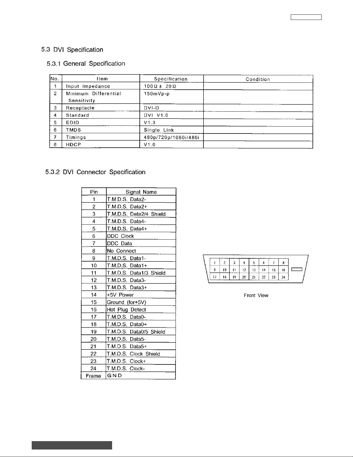
5.3 DVI Specification........................................................................................................................................................15
5.3.1 General Specification ..................................................................................................................................15
5.3.2 DVI Connector Specification........................................................................................................................15
6. Aspect Specification For Each Input Source......................................................................................................................16
6.1 Aspect Mode ..............................................................................................................................................................16
6.1.1 Aspect Mode: Off ........................................................................................................................................16
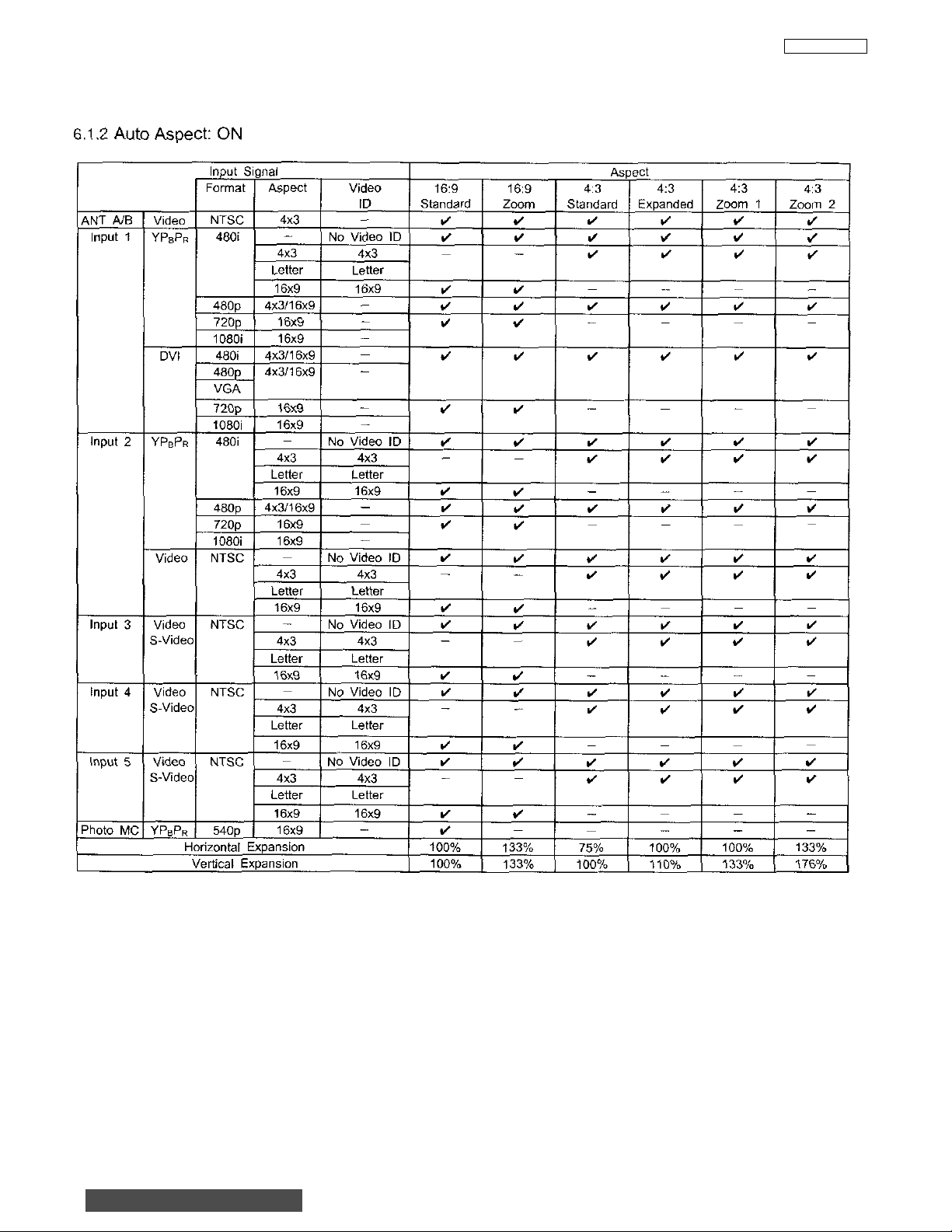
6.1.2 Aspect Mode: On ........................................................................................................................................17
6.1.3 Aspect Mode Resolution..............................................................................................................................18
6.1.4 Black Side Panel Operation ........................................................................................................................19
6.1.5 Vertical Position Operation ..........................................................................................................................19
6.2 PIP Mode....................................................................................................................................................................20
6.2.1 PIP Available Mode......................................................................................................................................20
6.2.2 PIP Mode Resolution ..................................................................................................................................21
II. FEATURES AND FUNCTIONS ..............................................................................................................................................22
1. Front Panel Controls ..........................................................................................................................................................22
2. Rear Panel Jacks ..............................................................................................................................................................25
3. Lamp Replacement ............................................................................................................................................................29
4. On-Screen-Display Features..............................................................................................................................................33
4.1 Video Setting..............................................................................................................................................................34
4.2 Channel Manager ......................................................................................................................................................38
5. Connecting A V Network......................................................................................................................................................40
5.1 AV Network Setup Wizard ..........................................................................................................................................41
5.2 AV Network Codes ....................................................................................................................................................42
5.3 How To Use AV Network ............................................................................................................................................43
5.4 How To Use The Aspect Mode ..................................................................................................................................48
III. ASSEMBLED P.W.B. ADJUSTMENT ..................................................................................................................................49
1. Memory Initialization ..........................................................................................................................................................49
Table 1. I
2
C Parameter List ................................................................................................................................................61
Table 2. Factory Reset ........................................................................................................................................................88
2. Factory Reset ....................................................................................................................................................................50
3. Raster Position Adjustment ................................................................................................................................................51
3.1 Mechanical Raster Position Adjustment ....................................................................................................................51
3.1.1 Geometry Specifications..............................................................................................................................51
3.1.2 Adjustment Mechanism................................................................................................................................52
3.1.3 Flow Chart For Adjustment..........................................................................................................................53
3.1.4 Adjustment Method......................................................................................................................................54
3.2 Electrical (I
2
C) Picture Position Adjustment................................................................................................................54
4. Display Area Specification ..................................................................................................................................................55
5. Amplitude Adjustment ........................................................................................................................................................56
5.1 RGB Amplitude Adjustment........................................................................................................................................56
6. Sub-Contrast Adjustment....................................................................................................................................................56
7. Ghost Adjustment ..............................................................................................................................................................57
8. V .COM (Flicker) Adjustment................................................................................................................................................57
9. NASH (Vertical Line) Adjustment........................................................................................................................................57
10.(Gamma) White Balance Adjustment..................................................................................................................................58
11.Color (White) Uniformity Adjustment ..................................................................................................................................59
12.Door Protection Operation Check ......................................................................................................................................60
13.Lamp Holder Protection Operation Check ..........................................................................................................................60
14.High Temperature Protection Operation Check..................................................................................................................60
TABLE OF CONTENTS
TO GO TO AN ADJUSTMENT, CLICK ON ITS HEADING BELOW

10
LC37/LC37F
IV. POWER P.W.B. ..................................................................................................................................................................92
1. Power Supply ....................................................................................................................................................................93
1.1 Ouput Voltage ..............................................................................................................................................................93
1.2 Portection Circuit Blcok Diagram................................................................................................................................94
V. TROUBLE SHOOTING FLOWCHART..............................................................................................................................95
VI. DC VOLTAGE ....................................................................................................................................................................96
VII. WAVEFORMS ..................................................................................................................................................................108
VIII. REPLACEMENT PARTS LIST ........................................................................................................................................114
IX. EXPLODED VIEW............................................................................................................................................................138
X. PRINTED CIRCUIT BOARD ............................................................................................................................................148
XI. CONNECTION DIAGRAM ..............................................................................................................................................160
XII. BLOCK DIAGRAM ..........................................................................................................................................................161
XIII. BASIC CIRCUIT DIAGRAM ............................................................................................................................................162
XIV. FINAL WIRING ................................................................................................................................................................175
XV. MAJOR ICs and UNITS ..................................................................................................................................................179

11
LC37/LC37F
• Six Aspect Modes
• Closed Caption Decoder
• 2-Tuner Picture in Picture
• Dual Antenna Inputs
•Video Input Sensor
•3 Dimensional Y/C Comb Filter
• Full 1080i HDTV capable.
• DVI with HDCP (High bandwidth Digital Content Protection V1.0 compatible).
• Photo MC (View digital still pictures from a memory card)
•Technology.
•Technology.
*SRS and the symbol are registered trademarks of SRS Labs, Inc. SRS technology is incorporated under license from SRS
Labs, Inc.
*Licensed by BBE Sound, Inc. under USP4638258 and 4482866. BBE and BBE symbol are registered
trademarks of BBE Sound, Inc. Manufactured under license from BBE Sound, Inc.
1.0 Features:
• Superfine Picture Quality
1280 Line Horizontal Resolution
• Remote (Controls many VCR brands, cable boxes, satellite boxes, and other audio equipment.)
• New Easy-to-Use (3-Language) On-Screen Menu
• New AV Network Infra-Red (IR) System
Control up to 4 components with one remote. (2 IR Mouse cables included.)
• Full Set of Input Jacks, including S-VIDEO
• COMPONENT VIDEO: Y-P
B/PR
Inputs:
•
Power Input . . . . . . . . . . . . .AC 120V, 60Hz
•
Stand-by Power . . . . . . . . . . . . . . . . . .0.6W
• Power Consumption
-Pmax . . . . . . . . . . . . . . . . . . . . . . . .172W
-Pave . . . . . . . . . . . . . . . . . . . . . . . .158W
• Antenna input impedance . . . . . . . . .75 Ohm
• Channel coverage . . . . . . . . . . . . . . .181ch.
VHF-Band . . . . . . . . . . . . . . . . . . . . .2 ~ 13
UHF-Band . . . . . . . . . . . . . . . . . . . .14 ~ 69
CATV Mid Band . . . . . . . . . . . . . . .A-5 ~ A-1
. . . . . . . . . . . . . . . . . . . . . . . . . . .A-I
Super Band . . . . . . . . . . . . . . . . . . . . .J-W
Hyper Band . . . . . . . . . . . . . . .W+1 - W+28
Ultra Band . . . . . . . . . . . . . . .W+29 - W+84
•Video . . . . . . . . . . . . . . . .1.0Vp-p, 75 Ohm
• S-Video
Luminance (Y) . . . . . . . . . .1.0Vp-p, 75 Ohm
Chrominance (C) . . . . . .0.286Vp-p, 75 Ohm
• Component Video
Luminance (Y) . . . . . . . . . . . . . . .1.0Vp-p, 75 Ohm
Chrominance (PB/PR) . . . . . . . . .0.7Vp-p, 75 Ohm
• Audio input Impedance . . . . . . . . . .47k Ohm
•Average input level . . . . . . . . . . . . . . . .470mVrms
• DVI - HDTV . . . . . . . . . . . . . . . . . . . . . .DVI 25pin
Dimensions:
50V500 60V500A
• Height (in.) 35 1/2 40 1/4
(mm) 901 1,025
•Width (in.) 54 5/8 63 3/8
(mm) 1,387 1,609
• Depth (in.) 16 3/8 20 1/2
(mm) 415 520
•Weight (lbs.) 119 139
(kg) 54.2 63
NOTE: Due to improvements, specifications in this serv-
ice manual are subject to change without notice.
Outputs:
•Video . . . . . . . . . . . . . . . . . . . . .1.0Vp-p. 75 Ohm
• Audio (Fixed) . . . . . . . . . . . . .470mVrms, 1k Ohm
• S-Video
Luminance (Y) . . . . . . . . . .1.0Vp-p, 75 Ohm
Chrominance (C) . . . . . .0.286Vp-p, 75 Ohm
I. SPECIFICATION
BACK TO ADJUSTMENTS

12
LC37/LC37F
I. SPECIFICATION
BACK TO ADJUSTMENTS

13
LC37/LC37F
I. SPECIFICATION
UE22331 UE22334
MEDIUM
14700 23
0.260
Black/White
HIGH
MAX ±3mm
MAX ±4mm
3. White Balance
HIGH: 14,700K+23MPCD (X=0.260±0.01, Y=0.280±0.01)
MEDIUM: 7500K+0MPCD (X=0.301±0.02, Y=0.311±0.02)
STANDARD: 6500K+0MPCD (X=0.313±0.02, Y=0.329±0.02)
Black/White: 5400K+0MPCD (X=0.334±0.02, Y=0.343±0.02)
at screen center
TYP
MIN
370 cd/m
2
240 cd/m
2
257 cd/m
2
166 cd/m
2
BACK TO ADJUSTMENTS
LC37 LC37F

14
LC37/LC37F
I. SPECIFICATION
BACK TO ADJUSTMENTS
15
LC37/LC37F
I. SPECIFICATION
BACK TO ADJUSTMENTS

16
LC37/LC37F
I. SPECIFICATION
BACK TO ADJUSTMENTS
17
LC37/LC37F
I. SPECIFICATION
BACK TO ADJUSTMENTS

18
LC37/LC37F
I. SPECIFICATION
6.1.3 Aspect Mode Resolution
BACK TO ADJUSTMENTS
4x3 Format 16x9 Format
75%
90%
4x3
4x3
75%
4x3
4x3
16:9
Standard
1386 dots
16:9
Zoom
4:3
Standard
998 dots (95%) 998 dots (95%)
4:3
Expanded
788 dots
75%
90%
16x9
16x9
75%
16x9
16x9
16:9
Standard
1386 dots
16:9
Zoom
4:3
Standard
4:3
Expanded
788 dots
75%
56%
Horizontal
Expansion
Ratio
(%)
4x3
4x3
75%
4:3
Zoom1
4:3
Zoom2
75%
56%
4:3 Expanded Mode
180
170
160
150
140
130
120
110
100
0102030405060708090100
Horizontal Position
16x9
16x9
75%
162%
113%
4:3
Zoom1
4:3
Zoom2
4:3
Standard
100%
4:3
Expanded
113%162% 162%

19
LC37/LC37F
I. SPECIFICATION
BACK TO ADJUSTMENTS
6.1.4 Black Side Panel Operation
Menu Black Side Panel: OFF
6.1.5 Vertical Position Operation
ANT
A/B
Video 1
Video 2
Video 3 Video
Video 4 Video
Video 5 Video
PIP Mode POP/PIP/SPLIT
Video NTSC 4x3 0 10 Step 0 10 Step 10 Step 10 Step
YPBP
DVI
YPBP
Video NTSC 4x3
S-Video
S-Video
S-Video
480i
R
480p
720p
1080i
480i
480p
720p
1080i
480i
R
480p
720p
1080i
NTSC 4x3
NTSC 4x3
NTSC 4x3
SURF12/STROBE
4x3
16x9
16x9 0 10 Step ____
4x3
16x9
16x9 0 10 Step ____
4x3
16x9
16x9 0 10 Step ____
16x9
16x9
16x9
16x9
Menu Black Side Panel: ON
Gray Side Panel
Vertical PositionInput
16:9
Standard
0 10 Step 0 10 Step 10 Step 10 Step
0 10 Step 0 10 Step 10 Step 10 Step
0 10 Step 0 10 Step 10 Step 10 Step
0 10 Step 0 10 Step 10 Step 10 Step
0 10 Step 0 10 Step 10 Step 10 Step
0 10 Step 0 10 Step 10 Step 10 Step
0 10 Step 0 10 Step 10 Step 10 Step
16:9
Zoom
4:3
Standard
Expanded
0
4:3
4:3
Zoom1
Black Side Panel
4:3
Zoom2

20
LC37/LC37F
I. SPECIFICATION
BACK TO ADJUSTMENTS

21
LC37/LC37F
I. SPECIFICATION
6.2.2 PIP Mode Resolution
BACK TO ADJUSTMENTS
POP Mode
4x3
788 dots
4x3
262 dots
4x3
4x3
4x3
262 dots
4x3
262 dots
PIP Mode
1386 dots 1042 dots
4x3
16x9
788 dots
16x9
4x3
1386 dots 304 dots
16x9
16x9
788 dots
344 dots
16x9
16x9
16x9
4x3
4x3
16x9
228 dots
SPLIT Mode STROBE Mode SURF12 Mode
4x3 4x3 4x3
788 dots
16x9
16x9
1386 dots 455 dots
788 dots
788 dots (95%)
16x9
4x3
4x3
4x3
16x9
788 dots
262 dots
228 dots
249 dots
332 dots344 dots693 dots

22
LC37/LC37F
II. FEATURES AND FUNCTIONS
1.0 FRONT PANEL CONTROLS
INPUT 5
S-VIDEO
EXIT
INPUT
SELECT
MENUVOL- VOL+ CH- CH+
VIDEO
AUDIO
L/MONO
R
PHOTO MC
PUSH
PUSH
MENU/SELECT button
This button allows you to enter the MENU, making it possible to set TV features to your preference without using the remote. This
button also serves as the SELECT button when in MENU mode.
INPUT/EXIT button
Press this button to select the current antenna source, VIDEO: 1, 2, 3, 4, 5 or alternate antenna source. Your selection is shown
in the top right corner of the screen. This button also serves as the EXIT button when in MENU mode.
CHANNEL selector
Press these buttons until the desired channel appears in the top right corner of the TV screen. These buttons also serve as
the cursor down () and up () buttons when in MENU mode.
VOLUME level
Press these buttons for your desired sound level. The volume level will be displayed on the TV screen. These buttons also serve
as the cursor left () and right () buttons when in MENU mode. When the TV power is turned OFF at a volume level 31 or greater,
the volume level will default to 30 when the TV is turned ON. However, if it is set to a level 30 or less, the volume level will be at
the level it was set when the TV is turned ON.
FRONT INPUT JACKS (INPUT 5)
Use these audio/video jacks for a quick hook-up from a camcorder or VCR to instantly view your favorite show or new recording.
Press the INPUT/EXIT button on the front control panel until VIDEO: 5 appears in the top right corner of the TV screen. If you have
mono sound, insert the audio cable into the left audio jack.
PHOTO MC
Insert a PC card adapter with your Photo memory card to view the digital still pictures (see page 44).
To view your digital pictures, an adapter is required. Below are adapters that are tested with your television. Please find out which
memory card you have and acquire it from your local source.
NOTES: Your remote control does not have an INPUT button. To change to video inputs, press VID1~VID5 buttons depending
on your choice. To change antenna source, press the ANT button on your remote control.
Memory Card Tested Samples
1. Secure Digital (SD) Dazzle 4 in 1 (DM-9400)
3. Memory Stick (MS) or
4. Smart Media (SM) SanDisk 4 in 1 (SDDR-6507)
5. Compact Flash I (CF I) Dazzle (DM-9000) or
6. Compact Flash II (CF II) SanDisk (SDCF-38)
7. xD Picture Card Olympus (MACF-10)
Notes: Adapter is subject to change for improvement.
Some terms used herein are trademarks of various companies.
BACK TO ADJUSTMENTS
23
LC37/LC37F
II. FEATURES AND FUNCTIONS
1.0 FRONT PANEL CONTROLS (CONT.)
IR RECEIVER/LEARNING AV NET sensor
The screen area acts as the IR receiver (remote sensor) and the LEARNING AV NET sensor of the TV. When using the remote
control, point it towards the screen for best response.
POWER button
Press this button to turn the TV on or off.
POWER light
This light is on during normal operation.
Light Blinking Slowly (2 seconds): television lamp is cooling down. It takes 12-15 seconds to warm up and about 2 minutes to cool
down.
TEMP indicator
This light is off during normal operation.
If this indicator is lit, the optic unit is too hot. If this indicator is blinking, the cooling fan has stopped. Please call service.
LAMP indicator - NORMAL OPERATION INDICATOR IS OFF
If light is lit, the lamp has failed. See page 29-32 for lamp replacement procedure. Consult your Hitachi dealer for proper part.
If light is blinking, lamp cover is not assembled securely after replacement.
PHOTO MC LED LIGHT INDICATOR
Shows the status of the memory card.
IMPORTANT NOTES:
1. A small number of missing, discolored, or lit all the time dots or pixels is characteristic of TFT LCD technology due to
manufacturing process for such technology irrespective of manufacturer. If your LCD has defective pixels, it should not be
considered defective.
2. Since LCD Rear PTV incorporates a high pressure lamp to display an image, it may take about one minute for the picture to
become stable, after the power has been turned on. After extended use, the picture may darken, the color may look unusual,
or the lamp “goes out,” (burns out). You may hear a “pop” sound when the lamp “goes out.” These are common
characteristics of the lamp, and should not be considered defective.
3. LCD Rear PTV incorporates an advanced cooling fan system to prevent from overheating. If you hear the cooling fan, it should
not be considered defective.
4. If you hear a “cracking” sound from the TV cabinet, it is due to the TV’s cabinet expanding and contracting due to room
temperature changes. It has no effect on the TV’s functions.
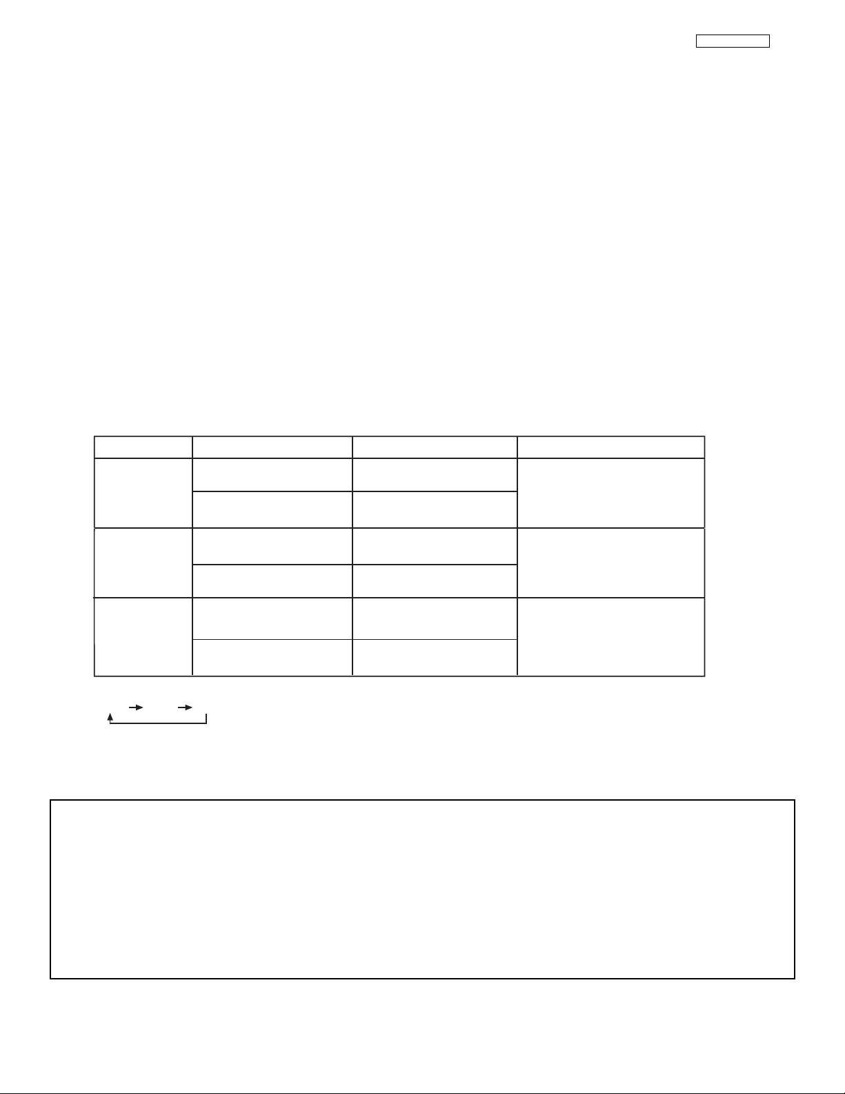
NOTES:
1.
INDICATOR INDICATION MEANING ACTION
Need to replace if
LAMP still does not light by
“Power On” again.
Check assembly condition of
LAMP UNIT
LAMP LED
TEMP
LED
LIGHT ON
BLINKING
LIGHT ON
BLINKING
NO LAMP LIGHT
or BROKEN LAMP
WRONG LAMP UNIT
ASSEMBLY / LAMP
DOOR OPEN
Too hot inside the
OPTIC unit
COOLING FAN STOPPED
POWER
LIGHT ON
SLOWLY BLINKING
2. If the LAMP, TEMP, and POWER LED are blinking in the order below, the television is warming up.
POWER TEMP LAMP
NORMAL
OPERATION
COOL DOWN

24
LC37/LC37F
II. FEATURES AND FUNCTIONS
1.0 FRONT PANEL CONTROLS (CONT.)
The front panel jacks are provided as a convenience to allow you to easily connect a camcorder or VCR as shown in the following
examples:
NOTE: 1. Completely insert connection cord plugs when connecting to front panel jacks. If you do not, the played back picture
may be abnormal.
2. If you have a S-VHS VCR, use the S-INPUT cable in place of the standard video cable.
3. If you have a mono VCR, insert the audio cable into the left audio jack of your TV.
INPUT 5
S-VIDEO
VIDEO
L/MONO
AUDIO
R
INPUT 5
S-VIDEO
VIDEO
L/MONO
AUDIO
R
25
LC37/LC37F
II. FEATURES AND FUNCTIONS
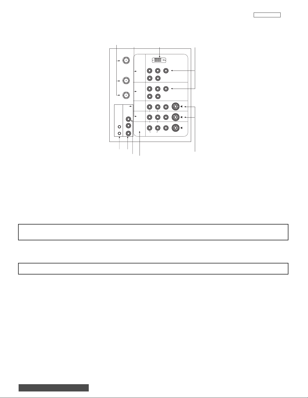
2.0 REAR PANEL JACKS
Antenna Input/Output
ANT A- A 75-Ohm RF antenna or CATV (Cable TV) input. ANT A can be displayed as a main picture or sub-picture.
ANT B- A 75-Ohm RF antenna or CATV (Cable TV) input. ANT B can only be displayed as a main picture. ANT B cannot be
displayed as a sub-picture.
TO CONVERTER- This antenna output allows the ANT A connection to pass directly to a different source, such as a cable box,
only when ANT B is displayed as a main picture.
Audio/Video Inputs 1, 2, 3 and 4
The VID1~VID4 buttons will select each video source each time they are pressed. Use the audio and video inputs to connect
external devices, such as VCRs, camcorders, laserdisc players, DVD players etc. (If you have mono sound, insert the audio cable
into the left audio jack.)
MONITOR OUT
These jacks provide fixed audio and video signals which are used for recording. Use the S-VIDEO Output for high quality video
output.
AUDIO TO HI-FI Output
These jacks provide variable audio output to a separate stereo amplifier. With this connection, the audio to the stereo can be
controlled by the television’s main volume.
CENTER IN (Input)
This jack is for stereo amplifiers with center signal capability. This feature allows the TV speakers to be used as a center speaker.
The TV must be set as a center channel by selecting “TV as Center” on the Internal Speakers Settings of the Audio Menu.
S-VIDEO Inputs 3 and 4
Inputs 3 and 4 provide S-VIDEO (Super Video) jacks for connecting equipment with S-VIDEO output capability.
NOTE: You may use VIDEO or S-VIDEO inputs to connect to INPUT 3 and 4, but only one of these inputs may be used at a
time.
NOTE: S-VIDEO output may be used for recording only when the input is of S-VIDEO type.
BACK TO ADJUSTMENTS
IR
BLASTER
ANT A
TO
CONVERTER
ANT B
AUDIO
TO HI-FI
CENTER
IN
L
R
INPUT 1
INPUT 2
INPUT 3
INPUT 4
MONITOR
OUT
P
R
R
P
R
R
R
R
R
AUDIO
P
B
(MONO)/L
AUDIO
P
B
(MONO)/L
AUDIO
(MONO)/L VIDEO
(MONO)/L VIDEO
L VIDEO
DVI-HDTV
Y
Y/VIDEO
S-VIDEO
S-VIDEO
S-VIDEO

26
LC37/LC37F
II. FEATURES AND FUNCTIONS
2.0 REAR PANEL JACKS (CONT.)
Component: Y-P
BPR
Inputs
Inputs 1 and 2 provide Y-P
BPR
jacks for connecting equipment with this capability, such as a DVD player or Set Top Box. You may
use composite video signal for INPUT:2.
NOTES: 1. Do not connect composite VIDEO and S-VIDEO to Input 3, 4 or 5 at the same time. S-VIDEO has priority
over VIDEO input.
2.
Your component outputs may be labeled Y, B-Y, and R-Y. In this case, connect the components B-Y output to the TV’s PBinput and
the components R-Y output to the TV’s PRinput.
3. Your component outputs may be labeled Y-CBCR. In this case, connect the component CBoutput to the TV’s PBinput and the
component CRoutput to the TV’s PRinput.
4. It may be necessary to adjust TINT to obtain optimum picture quality when using the Y-PBPR inputs.
5. To ensure no copyright infringement, the MONITOR OUT output will be abnormal, when using the Y-PBPRjacks.
6. Input 2 (Y/VIDEO) can be used for composite video and component video input.
IR Blaster
This jack provides IR output to your external components (VCR, Cable box, DVD player, etc.). With this connection, your external
components can automatically be controlled by the AV Net feature. This connection will allow you to control the external components
with your television’s remote control (see page 40).
DVI-HDTV Input (Input 1)
Use this DVI-HDTV Input for your external devices with DVI-HDTV output such as a Set-Top-Box, high-band DTV decoders, DVD
players with Digital Content Protection.
NOTES: 1. Only DTV format such as 1080i, 720p, 480i and 480p are available for DVI-HDTV input.
2. The DVI-HDTV input is NOT compatible when used with a DVD player from a personal computer.
3. When connecting a Set-Top-Box with a copy-protect digital out terminal, a high definition picture can be displayed
on the screen in its digital form.

27
LC37/LC37F
II. FEATURES AND FUNCTIONS
2.0 REAR PANEL JACKS (CONT.)
TYPICAL FULL-FEATURE SETUP
NOTES: 1.
Connect only 1 component to each input jack.
2. Follow connections that pertain to your personal entertainment system.
3. Composite video signal can be input to Input2~Input5.
4. Cables are not included with the purchase of this TV, except when noted as “provided”.
CONNECT TO
IR BLASTER
IR
Sensor
(Provided)
Outside antenna or
cable TV coaxial cable
2-Way signal splitter
IR
BLASTER
ANT A
TO
CONVERTER
ANT B
AUDIO
TO HI-FI
CENTER
IN
L
R
YP
INPUT 1
INPUT 2
INPUT 3
INPUT 4
MONITOR
OUT
DVD Player
OUTPUT
B/CBPR/CR
P
P
R
(MONO)/L
R
P
P
R
(MONO)/L
R
(MONO)/L VIDEO
R
(MONO)/L VIDEO
R
R
AUDIO
L R
B
AUDIO
B
AUDIO
L VIDEO
Y
Y/VIDEO
DVI-HDTV
S-VIDEO
S-VIDEO
S-VIDEO
HDTV Set-Top Box
P
Y P
B
R
OUTPUT
L R
DIGITAL OUTPUT
D-VHS
LR
OUTPUT
ANT
IN
S-VIDEO
VCR #1
OUTPUT
VLR
Cable TV Box
INPUT
OUTPUT
LR
CENTER OUTPUT
INPUT
Stereo System Amplifier
CONNECT TO
IR BLASTER
IR
Sensor
S-VIDEO
VCR #2
(Provided)
V L R
INPUT
V L R
S-VIDEO
OUTPUT
Laserdisc player, VCR,
camcorder, etc.

28
LC37/LC37F
II. FEATURES AND FUNCTIONS
2.0 REAR PANEL JACKS (CONT.)
• S-VIDEO connections are provided for high performance laserdisc players, VCRs etc. that have this feature. Use these
connections in place of the standard video connection if your device has this feature.
• If your device has only one audio output (mono sound), connect it to the left audio jack on the television.
• Refer to the operating guide of your other electronic equipment for additional information on connecting your hook-up cables.
•Asingle VCR can be used for VCR #1 and VCR #2, but note that a VCR cannot record its own video or line output (INPUT: 3 in
the example on page 27). Refer to your VCR operating guide for more information on line input-output connections.
•You may use VIDEO or S-VIDEO inputs to connect to Input 3, Input 4 or Input 5, but only one of these may be used at a time.
• Connect only 1 component (VCR, DVD player, camcorder, etc.) to each input jack.
• COMPONENT: Y-PBPR (Input 1 &2) connections are provided for high performance components, such as DVD players and settop-boxes. Use these connections in place of the standard video connection if your device has this feature. Input 2 accepts
both composite and component video signals.
•Your component outputs may be labeled Y, B-Y, and R-Y. In this case, connect the components B-Y output to the TV’s PBinput
and the components R-Y output to the TV’s PRinput.
•Your component outputs may be labeled Y-CBCR. In this case, connect the components CBoutput to the TV’s PBinput and
the components CRoutput to the TV’s PRinput.
•You may use composite video signal for Input 2~Input 5.
• It may be necessary to adjust TINT in the Video menu to obtain optimum picture quality when using the Y-PBPRinputs.
•To ensure no copyright infringement, the MONITOR OUT output may be abnormal, when using the
Y-PBP
R
or DVI jacks.
• When using DVI input from a Set-Top-Box, it is recommended to use a 1080i or 720p input signal.

29
LC37/LC37F
II. FEATURES AND FUNCTIONS
3.0 LAMP REPLACEMENT
Lamp Replacement
After extended use, if the TV picture turns dark, the color looks unusual or LAMP INDICATOR light
turns on, then it is time to replace the lamp with a new lamp.
Lamp Life
The lamp life may vary based on usage of the LCD Rear PTV. Turning on and off frequently may
shorten the life of the lamp.
WARNING:
The lamp gets very hot! The lamp may explode if improperly handled. To avoid injury, please observe the following
precautions.
• Do not open lamp compartment or attempt to remove lamp assembly unless the lamp assembly is being replaced.
• Unplug the product’s power cord from the AC outlet before attempting to replace the lamp assembly.
• If the lamp is in use when failure occurs or if the lamp has exploded, wait at least 30-45 minutes for the lamp to
cool before opening the lamp compartment or touching the lamp assembly or any broken pieces.
• Broken lamp pieces can cause injury. Handle with gloves to avoid cuts.
• Do not place any foreign objects inside the lamp compartment.
• When installing a new lamp, follow handling instruction included with the new lamp. Do not touch glass surface of
new lamp.
•
The lamp in this product contains Mercury. Dispose of properly in accordance with applicable environmental
laws. For Recycling and Disposal information, contact your respective governmental agencies or the Electronic
Industries Alliance at www.eiae.org (in the U.S.) or Electronic Product Stewardship Canada at www.epsc.ca (in
Canada).
CAUTION!
A ”LAMP” indicator will light when lamp becomes hot. Unplug product’s power cord from the AC outlet and allow
lamp to cool for at least 30-45 minutes. If “LAMP” indicator is still lit, check the lamp unit assembly.
NOTES:
• Contact your Hitachi dealer for a new lamp unit. Using other lamps may cause damage to
the TV Set.
TYPE NAME: LC37 LAMP ASSEMBLY
PART NUMBER: UX21511
• When replacing the lamp, let it cool down completely, for approximately 30 to 45 minutes
after the power has been switched off and A.C. cord has been unplugged.
• Do not touch the glass of the new lamp or make it dirty which can shorten the life
of the lamp and reduce the picture quality.
• Keep the lamp out of the reach of children and away from flammable materials.
• Do not pour water onto the removed lamp or put any object inside the lamp.
• Once the lamp is removed, do not put flammable materials and metal objects inside the
lamp receptacle on the TV set. Do not touch the receptacle.
• Install the new lamp securely, otherwise the picture may become dark or it may cause
severe overheating.
• Install the lamp cover correctly, otherwise power will not come on.
•
The lamp in this product contains Mercury. Dispose of properly in accordance with
applicable environmental laws. For Recycling and Disposal information, contact your
respective governmental agencies or the Electronic Industries Alliance at www.eiae.org (in
the U.S.) or Electronic Product Stewardship Canada at www.epsc.ca (in Canada).
BACK TO ADJUSTMENTS

30
LC37/LC37F
II. FEATURES AND FUNCTIONS
3.0 LAMP REPLACEMENT (CONT.)
1. Turn off the main power switch and unplug the power cord. Wait at least 30 minutes to allow the lamp to cool down before
replacing it.
NOTE:
THE LAMP IS VERY HOT AND MAY CAUSE FIRE OR SEVERE BURNS. WAIT AT LEAST 30~45
MINUTES TO ALLOW THE LAMP TO COOL BEFORE PROCEEDING WITH LAMP REMOVAL.
2. Remove the front cover from the TV set. This is held by a snap on. Pull the front cover outwards until the quick snap on
disengages.
NOTE: The lamp in this product contains Mercury. Dispose of properly in accordance with applicable environmental
laws. For Recycling and Disposal information, contact your respective governmental agencies or the
Electronic Industries Alliance at www.eiae.org (in the U.S.) or Electronic Product Stewardship Canada at
www.epsc.ca (in Canada).
120V
PUSH
POWER
FRONT COVER
LAMP COMPARTMENT
PULL
FRONT COVER
PUSH
 Loading...