

Hitachi 60UX55K, 60UX54B, 60SBX72B, 50UX53K, 50UX52B Owner’s Manual
...
PROJECTION COLOR TV
OPERATING GUIDE
_ w
IMPORTANT SAFEGUARDS
FIRST TIME USE
THE GENIUS
REMOTE CONTROL
ULTRATEC BIT-MAP
ON-SCREEN DISPLAY
2-4
5-18
19-30
31-59
__,_ _"
USEFUL INFORMATION INDEX 60-67
Follow all warnings and instructions marked on this projection television.
[__t CAUTION ],_
CAUTION: TO REDUCE THE RISK OF ELECTRIC SHOCK,
REFER SERVICING TO QUALIFIED SERVICE PERSONNEL.
RISK OF ELECTRIC SHOCK
DO NOT OPEN
DO NOT REMOVE COVER (OR BACK).
NO USER SERVICEABLE PARTS INSIDE.
WARNING:
TO PREVENT FIRE OR SHOCK HAZARD, DO NOT EXPOSE
THIS PROJECTION TELEVISION TO RAIN OR MOISTLIRE.
IMPORTANT
The lightning flash with arrowheacl symbol, within an equilateral tri-
angle, is intended to alert the us_=rto the presence of uninsulated
"dangerous voltage" within the prcduct's enclosure that may be of a
sufficient magnitude 1oconstitute a risk of electric shock to persons.
The exclamation point within an equilateral triangle, is intended to
alert the user to the presence of important operating and mainte-
nance (servicing) instructions in the literature accompanying the
appliance.
NOTE:
• ]here are no user serviceable parts inside the television.
• Model and serial numbers are indicated on back side of the television.
• ]his television is not intended for use in a computer room.
POWER SOURCE
This projection television is designed to operate on 120 volts 60Hz, AC: current.
Insert power cord into a 120 volt 60Hz outlet.
TO PREVENT ELECTRIC SHOCK, DO NOT USE THE TELEVISION'S (POLARIZED) PLUG
WITH AN Ex"rENSlON CORD, RECEPTACLE, OR OTHER OUTLET UNL.ESS THE BLADES
AN[) GROUND TERMINAL CAN BE FULLY INSERTED TO PREVENT BLADE EXPOSURE.
NEVER CONNECT THE TELEVISION TO 50HZ, DIRECT CURRENT, OR ANYTHING OTHER
THAN THE SPECIFIED VOLTAGE.
NOTE: This television receiver will display television closed captioning, (r_ or E_), in accordance with para- _1
graph 15.119 of the FCC rules.
If the television does not operate properly, unplug the television and call your authorized dealer or service shop.
,_. _ CAUTION: N_v_rr_m_v_th_ba_kc_v_fth_t_vi_i_na_thiscanexp_y_ut_v_ryhighv_tag_an_therh_z_r_ I
2
I
SAFETY TIPS
IMPORTANT SAFEGUARDS
CAUTION:
• Read all of these instructions.
• Save these instructions for later use.
• Follow all warnings and instructions marked
on the television.
Our reputation has been built on the quality, performance, and ease of service of HITACHI televisions
Safety i.,;also foremost in our minds in the design of these units. To help you operate these products properly, this section illustrates safety tips which
will be of benefit to you. Please read it carefully and apply the knowledge you obtain from it to the proper operation of your HITACHI television.
Please fill out your warranty card and mail it to HITACHI. This will enable HITACHI to notify you promptly in the impr3bable event that a safety
problem should be discovered in your product model.
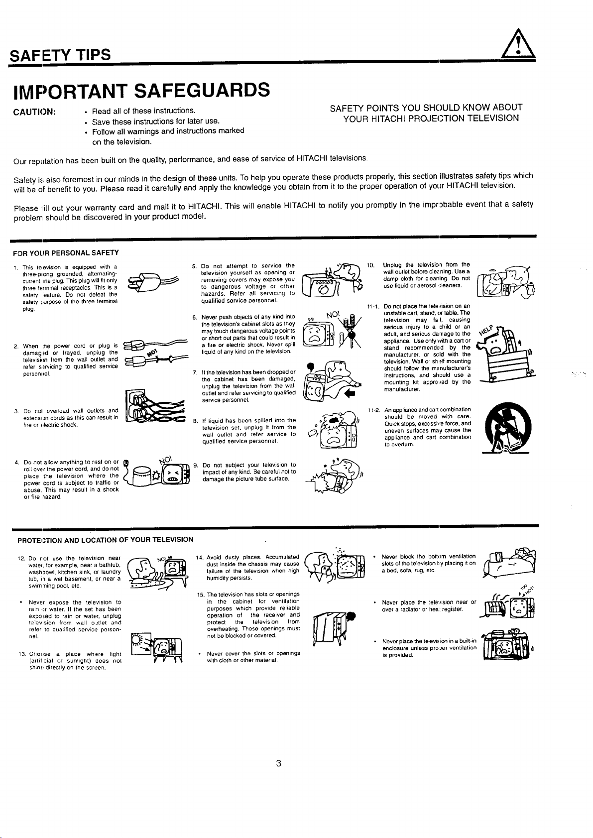
FOR YOUR PERSONAL SAFETY
1. This leevision is equippecl with a
three-plong grounded, alternating-
current ine plug. This plug will fit only
three terminal receptacles. This is a
safety :eature. Do not defeat the
safety purpose of the three terminal
plug.
2. When the power cord or plug is
damag,.=d or frayed, unplug the
television from the wall outlet and
refer s,_rvicing to qualified service
personnel.
3. Do nol overload wall outlets and
extensi 3n cords as this can result in
fire or electric shock.
......r'--"_ _
Do not attempt to service the
television yoursetl as opening or
removing covers may expose you
to dangerous voltage or other
hazards. Refer all servicing to
qualified service personnel.
Never push objects of any kind into
the television's cabinet slots as they
may touch dangerous voltage points
or short out parts that could result in
a fire or electric shock. Never spill
liquid of any kind on the television.
If the television has been dropped or
the cabinet has been damaged,
unplug the television from the wall
outlet and refer servicing to qualified
service personnel.
If liquid has been spilled into the
television set, unplug it from the
wall outlet and refer service to
qualified service personnel.
SAFETY POINTS YOU SHOULD KNOW ABOUT
YOUR HITACHI PROJECTION TELEVISION
wall outlet before cle_ning. Use a
damp cloth for ceaning+ Do not
use liquid or aerosol ,_leaners.
10. Unplug the televisio'l from the 1----_.
_.,_OI. unstable cart, stand, <)rtable. The
__ television may fa I, causing
ocf_ _) should be moved with care.
o _ Qu_ck stops, excessi_,e force, and
_;.t" .'- <" _1ol | uneven surfaces may cause the
11-1. Do not place the tele/ision on an
serious injury to a child or an
adult, and serious damage to the _x"_l[ _
appliance. Use o3ly with a cart or
stand recommendE!d by the .B,/_#.-_ j|li_.. "
manufacturer, or scld with the
television. Wall o," sh _ff mounting
instructions, and should use a
mounting kLt appro/ed by the
manufacturer.
should lollow the m_nufacturer's
1t-2. An appliance and carl combination
appliance and cart combination
to overturn.
4. Do not allow anything to rest on or
roll over the power cord, and do not 9.
place the television wl'ere the
power cord is subject to traffic or
abuse. This may result in a shock
or fire ;_azard.
PROTEI3TION AND LOCATION OF YOUR TELEVISION
12. Do rot use the television near
water, for example, near a bathlub,
wash:_owl, kitchen sink, or laundry
tub, i3 a wet basement, or near a
swim'ning pool, etc.
Never expose the '_elevision to
rain or water. If the set has been
expo_,ed to rain or water, unplug
television from wall oJtlet and
refer to qualified service person-
nel.
13 Choose a place where Fight
(artilcia] or sunlight) does not
shine directly on the screen.
Do not subject your television to
impact of any kind. Be careful not to
damage the picture tube surface.
14.
dust inside the chassis may cause
failure of the television when high
humidity persists.
15.
The television has slots or opemngs
in the cabinet for ventilation
purposes which provide reliable
operation of the receiver and
protect the television trom
overheating. These openings must
not be blocked or covered.
Never cover the slots or openings
with cloth or other material.
• Never block the bottom ventilation r I_i,_1_
slots of the television by placing it on
a bed. sofa, rug, etc.
• Never place the :e]e','ision near or __
over a radiator or hea: register.
Never place the teevi., ion in a built-in
enclosure unless pro;_er ventilation
is provided.
/.k
PROTECTION AND LOCATION OF YOUR TELEVISION
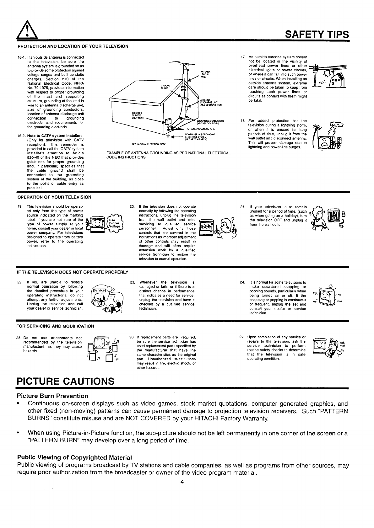
16-1. If an outside antenna is connected
to the television, be sure the
antenna system is grounded so as
to provide some protection against
voltage surges and built-up static
charges. Section 810 of the
National Electrical Cede, NFPA
No. 70-1975, provides information
with respect to proper grounding
of the mast and supporting
structure, grounding of the lead-in
wire to an antenna discharge unit,
size of grounding conductors,
location of antenna discharge unit
connection to grounding
electrode, and requirements for
the grounding electrode.
16-2. Note to CATV system installer:
(Only for television with CATV
reception). This reminder is
provided to call the CATV system
installer's attention to Article
820-40 of the NEC that provides
guidelines for proper grounding
and, in particular, specifies that
the cable ground shall be
connected to the grounding
system of the building, as close
to the point of cable entry as
practical.
OPERATION OF YOUR TELEVISION
19. This television should be operat-
ed only from the type of power
source indicated on the marking
label. If you are not sure of the
lype of power su;_ply at your
home, consult your dealer or local
power company. For televisions
Jesigned to operate from battery
Dower, refer to the operating
instructions.
EXAMPLE OF ANTENNA GROUNDING AS PER NATIONAL ELECTRICAL
CODE INSTRUCTIONS.
GROUNO_CO_DOCT_$
_R SERVI(_¢,_JNO_
ELECTRCOIE SYSTEM
NEC _TK_L ELECTR_.AL
20. Ifthe letevision does not operate
normally by following the operating
instructions, unplug the lelevision
from the wall Outlet and refer
servicing Io qualilied service
personnel. Adjust only those
controls that are covered in the
instructions as improper adjustment
of other controls may result in
damage and will often require
extensive work by a qualified
service technician to restore the
television to normal operation.
{NEC _T 250 PART H)
_rrEt_W
[_so._R6_UNIT
(NE¢ 9ECTICt_ 810-_ I
C4_OUNO_G¢_O_:TO_S
_ECSEC1_ONate-21)
SAFETY TIPS
17. An outside allferna system should
not be located in the vicinity of
overhead power lines or other ,__
electrical lights :,r power circuits, [_
or where il C_Lnf_ll into such power _" _
Iines or circuits. When installing an U ._, fouo_
outside antenna system, extreme L_° ...L_,_
care should f)e f=Lkento keep from
touching such power lines or
circuits as conta(:t with them might
be fatal.
18. For added pr(Itection for the
television duzing a lightning storm,
or when it is unused for long
periods of time, Jnplug it from the
wall outlet an::l di:;connect antenna.
This will precen_ damage due to
lightning and pov,er-line surges.
21. If your television is to remain __~r'_ __,
unused for a pe iod of time, (such
as when going (m a holiday), turn
the television CFF and unplug it "
from the wal ou let.
IF THE TELEVISION DOES NOT OPERATE PROPERLY
22. If you are unable to restore
normal operation by following
the detailed procedure in your
operating instructions, do not
attempt any further adjustments.
Unplug the television and call
your dealer or servh..e technician.
23. Whenever the television is
damaged or fails, or if there is a
distinct change in performance
that indicates a need for service.
unplug the television and have it
checked by a qualified service
technician.
24. It is normal for some televisions to
make occasioral snapping or
popping sounds, particularly when
being turne:l cn or off. If the
snapping or i.;,opping is continuous
or frequent, unplug the set and
consult your d_aler or service
technician.
FOR SERVICING AND MODIFICATION
25. DO not use attaclnments not
recommended by tl'e television
manufacturer as they may cause
h_zards.
,,f_ 26. If replacement parts are required, 27. Upon completion of any service or l ""
'[_ be sure the service technician has repairs to the teevislen, ask the ,c.--...-_ . ask
used replacement parts specified by service technician to perform me!
the manufacturer that have the routine safety ch,_cks to determine
same characteristics as the original that the television is in safe
part. Unaulhorized substitutions operating condition.
may resull in fire, electric shock, or
other hazards.
PICTURE CAUTIONS
Picture Burn Prevention
e Continuous on-screen displays such as video games, stock market quotations, compule_ generated graphics, and
other fixed _inon-moving) patterns can cause permanent damage to projection television re;eivers. Such "PATTERN
BURNS" constitute misuse and are NOT COVERED by your HITACHI Factory Warranty.
* When using Picture-in-Picture function, the sub-picture should not be left permanently inone corner of the screen or a
"PATTERN BURN" may develop over a long period of time.
Public Viewing of Copyrighted Material
Public viewing of programs broadcast by TV stations and cable companies, as well as programs from other sources, may
require prior authorization from the broadcaster 9r owner of the video program rnaterial.
4
ACCESSORIES
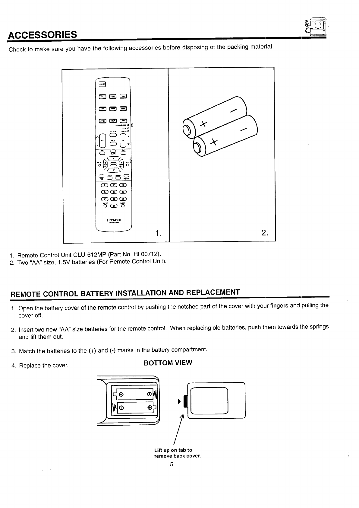
Check to make sure you have the following accessories before disposing of the packing material.
_o
_o
_ _ o
_ CiDCD
_CiD_
H rrAP_l-ii
,._ .J
1. Remote Control Unit CLU-612MP (Part No. HL00712).
2. Two "AA" size, 1.5V batteries (For Remote Control Unit).
REMOTE CONTROL BATTERY INSTALLATION AND REPLACEMENT
1. O_centhe battery cover of the remote control by pushing the notched part of the cover with your fingers and pulling the
cover off.
2. Insert two new "AA" size batteries for the remote control. When replacing old batteries, push them towards the springs
and lift them out.
3. Match the batteries to the (+) and (-) marks in the battery compartment.
4. Replace the cover. BOTTOM VIEW
o
=
:!1,/IE
Lift up on tab to
remove back cover.
5
HOW TO SET UP YOUR NEW HITACHI PROJECTION TV
ANTENNA
Unless your TV is connected to a cable TV system or to a centralized antenna system, a good outdoor color "TV antenna is
rec:ommended for best performance. However, if you are located in an exceptionally good signal area ":h_.tisfree from interference and
mLJltipleimage ghosts, an indoor antenna may be sufficient.
LOCATION
Select an area where sunlight or bright indoor illumination will not fall directly on the picture, screen. Also, be sure that the location
selected allows a free flow of air to and from the perforated back cover of the set.
To avoid cabinet warping, cabinet color changes, and increased chance of set failure,, do not place the TV where temperatures can
become excessively hot, for example, in direct sunlight or near a heating appliance, etc.
VIFWING
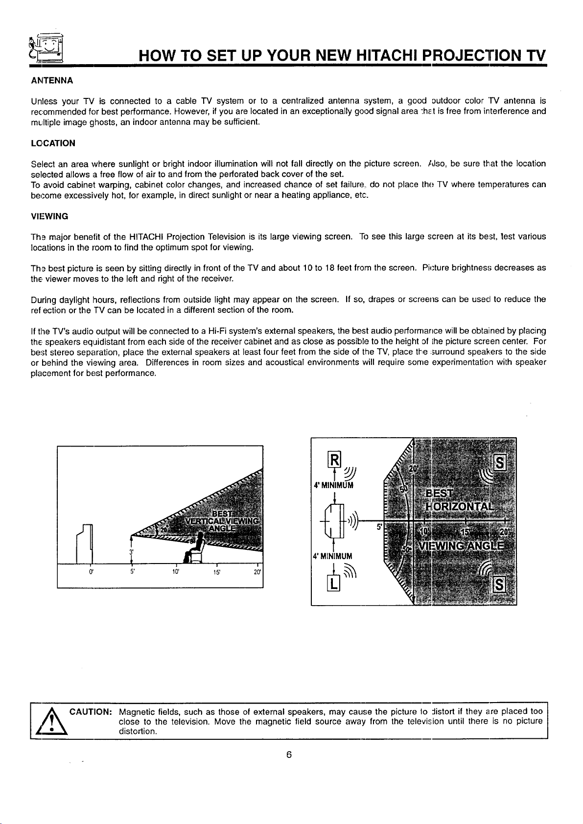
Th_ major benefit of the HITACHI Projection Television is its large viewing screen. "Tosee this large screen at its beast,test various
locations in the room to find the optimum spot for viewing.
Th_= best picture is seen by sitting directly in front of the TV and about 10 to 18 feet from the screen. Pi_'ture brightness decreases as
the viewer moves to the left and right of the receiver.
During daylight hours, reflections from outside light may appear on the screen. If so, drapes or screens can be usecl to reduce the
refection or the TV can be located in a different section of the room.
Ifthe TV's audio output will be connected to a Hi-Fi system's external speakers, the best audio performance will be obtained by placing
the speakers equidistant from each side of the receiver cabinet and as close as possible to the height of Lhepicture screen center. For
be=3tstereo separation, place the external speakers at least four feet from the side of the TV, place the :surround speakers to the side
or behind the viewing area. Differences in room sizes and acoustical environments will require some experimentation with speaker
placement for best performance.
4' MINIMUM
4' MINIMUM
0' 5' 10'
A CAUTION: Magnetic fields, such as those of external speakers, may cause the picture lo :listort if they are placed too I
_";.,.._ distortion.
close to the television. Move the magnetic field source away from the television until there is no picture
I
I
HOOK-UP CABLES AND CONNECTORS
Most video/audio connections between components can be made with shielded video and audio cables that have phono connectors.
For be.,;tperformance, video cables should use 75-Ohm coaxial shielded wire. Cables can be purchased from most stores that sell
audio/video products. Below are illustrations and names of common connectors. Before purchasing any cables, be sure of the output
and input connector types required by the various components and the length of each cable.
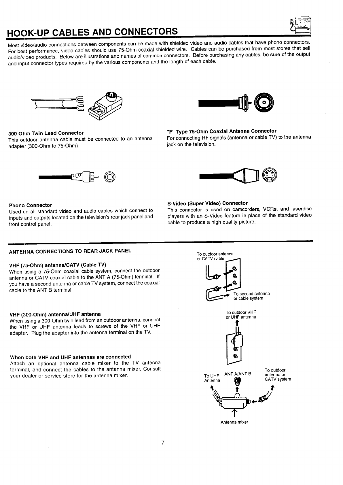
300-Ohm Twin Lead Connector
This outdoor antenna cable must be connected to an antenna
adapter (300-Ohm to 75-Ohm).
Phono Connector
Used on all standarcl video and audio cables which connect to
inputs ;]nd outputs located on the television's rear jack panel and
front control panel.
ANTENNA CONNECTIONS TO REAR JACK PANEL
VHF (75-Ohm) antenna/CATV (Cable "rv)
When using a 75-Ohm coaxial cable system, connect the outdoor
antenna or CATV coaxial cable to the ANT A (75-Ohm) terminal. If
you hace a second antenna or cable TV system, connect the coaxial
cable to the ANT B terminal.
"F" Type 75-Ohm Coaxial Antenna Connector
For connecting RF signals (antenna or cable "IV) to the antenna
jack on the television.,
S-Video (Super Video) Connector
This connector is used on camcorders, VCRs, and laserdisc
players with an S-Video feature in place of the stan4ard video
cable to produce a high quality picture.
Tooutd(_orantenna
orCATVcable
(_' oT°¢_qeb,c_:nsysatntenna
VHF ('100-Ohm) antenna/UHF antenna
When Jsinga 300-Ohm twin lead from an outdoor antenna, connect
the VHF or UHF antenna leads to screws of the VHF or UHF
adapter. Plug the adapter into the antenna terminal on the TV.
When both VHF and UHF antennas are connected
Attach an optional antenna cable mixer to the TV antenna
terminal, and connect the cables to the antenna mixer. Consult
your dealer or service store for the antenna mixer.
To outdoor VH:
or UHF antenna
t
ToUHF ANTNANT B antennaor
Antenna _) CATV systern
_r
Antenna mixer
Tooutdoor
FRONT PANEL CONTROLS
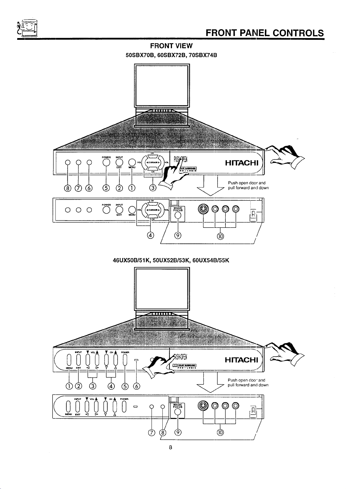
FRONT VIEW
50SBX70B, 60SBX72B, 70SBX74B
HITACHI
Push open door and
pull forward and down
O O O
pOWEROINPUT
O
E.Y3T
46UX50B/51K, 50UX52B/53K, 60UX54B/55K
I
/
HITACHI
.[
Push open doo" and
/7 pull forward and down
I
FRC)NT PANEL CONTROLS
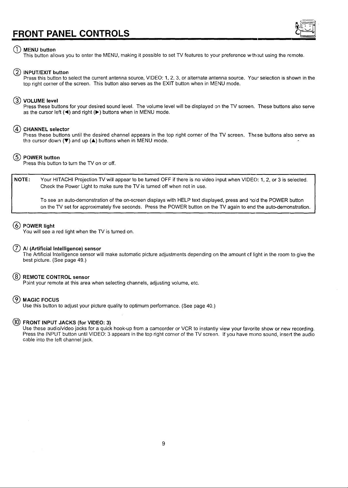
(_ MF-NU button
This button allows you to enter the MENU, making it possible to set -IV features to your preference w,thout using the remote.
(_) INPUT/EXIT button
Press this button to select the current antenna source, VIDEO: 1, 2, 3, or alternate antenna source. Your selection is shown in the
top right corner of the screen. This button also serves as the EXIT button when in MFNU mode.
____VOLUME level
Press these buttons for your desired sound level. The volume level will be displayed on the "IV screen. These buttons also serve
as the cursor left ('4) and right (1_) buttons when in MENU mode.
(_) CI-IANNEL selector
Press these buttons until the desired channel appears in the top right corner of the TV screen. "l"hE_sebuttons also serve as
th_ cursor dowl'l (Y) and up (A) buttons when in MENU mode.
(_) POWER button
Press this button to turn the TV on or off.
NOTE:
(_ POWER light
You will see a red light when the -IV is turned on.
/_ AI (Artificial Intelligence) sensor
The Artificial Intelligence sensor will make automatic picture adjustments depending on the amount of light in the room to give the
(_ REMOTE CONTROL sensor
Q MAGIC FOCUS
(_ FRONT INPUT JACKS (for VIDEO: 3)
Your HITACHI Projection TV will appear to be turned OFF if there is no video input when VIDE(): 1, 2, or 3 is selected.
Check the Power Light to make sure the TV is turned off when not in use.
To see an auto-demonstration of the on-screen displays with HELP text displayed, press and qold the POWER button
on the "I-V set for approximately five seconds. Press the POWER button on the TV again to end the auto-demonstration.
best picture. (See page 49.)
Point your remote at this area when selecting channels, adjusting volume, etc.
Use this button to adjust your picture quality to optimum performance. (See page 40.)
Use these audio/video jacks for a quick hook-up from a camcorder or VCR to instantly view your favorite show or new recording.
Press the INPLIT button until VIDEO: 3 appears in the top right corner of the IV screen. If you have mono sound, insert the audio
c;]ble into the left channel jack.
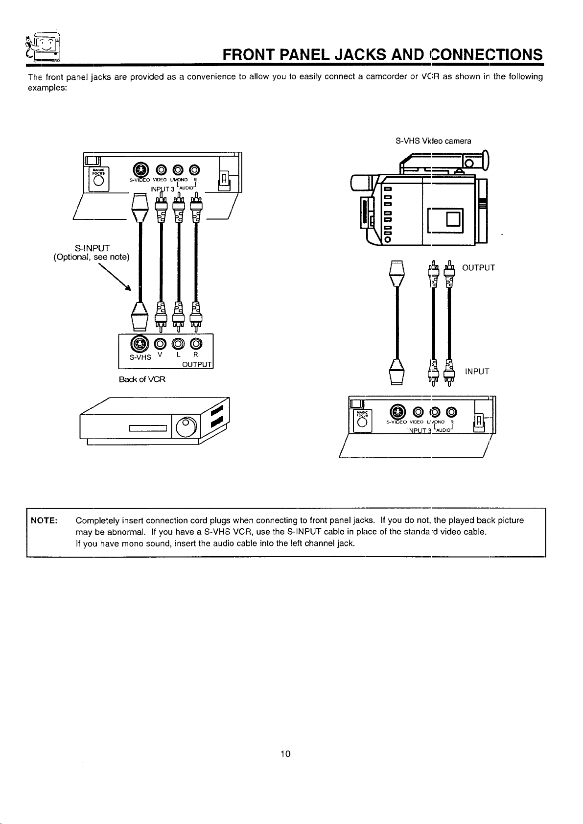
__ FRONT PANEL JACKS AND CONNEC.TIONS
The front panel jacks are provided as a convenience to allow you to easily connect a camcorder or VCR as shown it7 the following
examples:
S-VHS Video camera
°
(Optional se__
-7
• i_ =°E° __
S-VHS V L R
I@o*o
Back ofVCR
OUTPUT
J •
t ,-,
D
D
D
0
0
t
OUTPUT
INPUT
NOTE:
Completely insert connection cord plugs when connecting to front panel jacks. If you do not, the played bac,k picture
may be abnormal• If you have a S-VHS VCR, use the S-INPUT cable in place of the standard video cable.
If you have mono sound, insert the audio cable into the left channel jack.
10
REAR PANEL JACKS
O
REAR SPEAKER / ANTA
/
® 15]J
CSTOP
CONNECT ONLY 8 OHM SPEAKERS
DO NOT SHORT CIRCUIT
THESE TERMINALS
(Such damage Is NOT COVERED
by yoL)r television warranty)
O
> @
ANT B
()
6"16°
©,©/,G
M'
(i
SUB
@=1@
1'-2'_-
® @
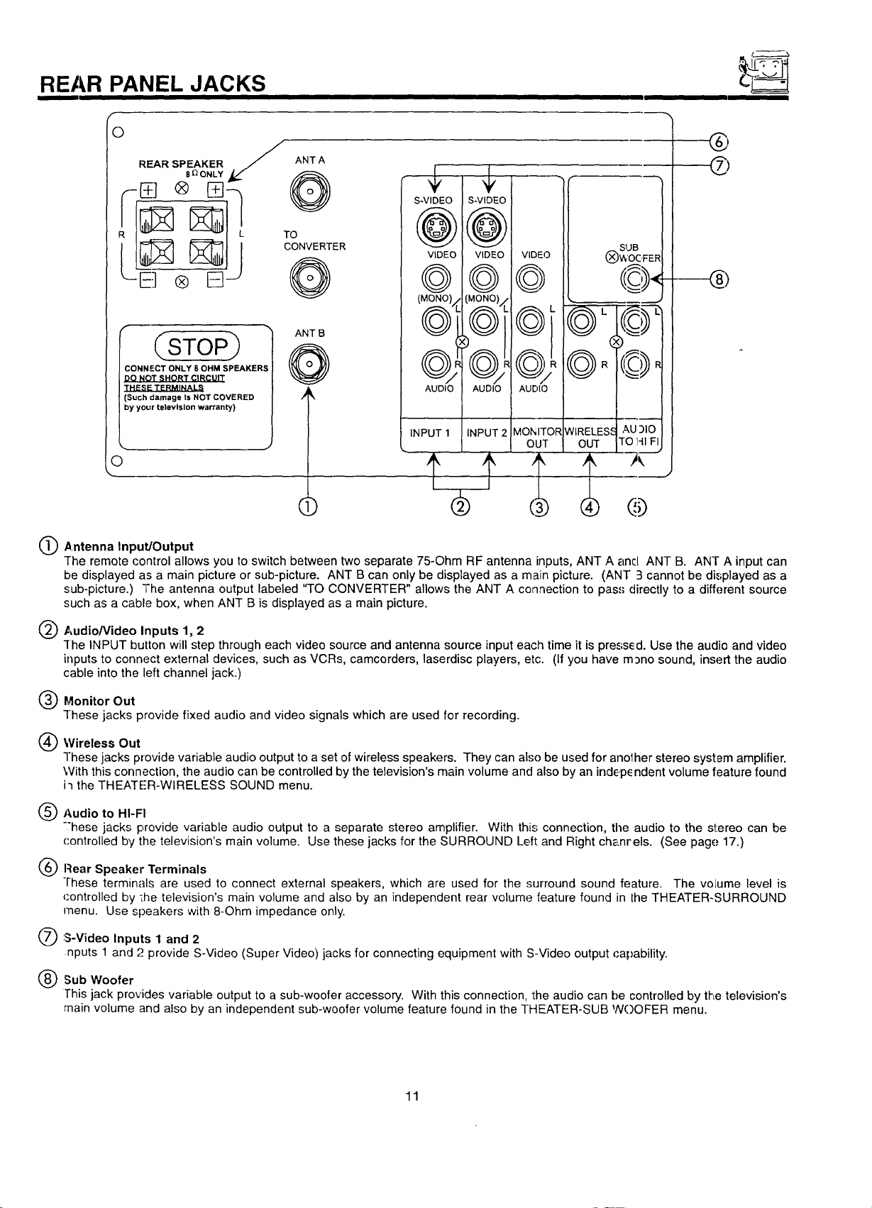
Antenna Input/Output
The remote control allows you to switch between two separate 75-Ohm RF antenna inputs, ANT A and ANT B. ANT A input can
be displayed as a main picture or sub-picture. ANT B can only be displayed as a main picture. (ANT 3 cannot be displayed as a
sub-picture.) "The antenna output labeled "TO CONVERTER" allows the ANT A connection to pass directly to a different source
such as a cable box, when ANT B is displayed as a main picture.
Audio/Video Inputs 1, 2
-[he INPUT button will step through each video source and antenna source input each time it is pressed. Use the audio and video
inputs to connect external devices, such as VCRs, camcorders, laserdisc players, etc. (If you have m_no sound, insert the audio
cable into the left channel jack.)
@Monitor Out
These jacks provide fixed audio and video signals which are used for recording.
Wireless Out
These jacks provide variable audio output to a set of wireless speakers. They can also be used for anolher stereo system amplifier.
With this connection, the audio can be controlled by the television's main volume and also by an indep_ ndent volume feature found
i'l the THEATER-WIRELESS SOUND menu.
@Audio to HI-FI
"'hese jacks provide variable audio output to a separate stereo amplifier. With this; connection, the audio to the stereo can be
controlled by the television's main volume. Use these jacks for the SURROUND Left and Right chanrels. (See page 17.)
Rear Speaker Terminals
These terminals are used to connect external speakers, which are used for the surround sound feature. The volume level is
(:ontrolled by ';he television's main volume and also by an independent rear volume feature found in the THEATER-SURROUND
menu. Use speakers with 8-Ohm impedance only.
'S-Video Inputs 1 and 2
nputs 1 and "._provide S-Video (Super Video) jacks for connecting equipment with S-Video output capability.
Sub Woofer
This jack provides variable output to a sub-woofer accessory. With this connection, the audio can be controlled by the television's
main volume and also by an independent sub-woofer volume feature found in the THEATER-SUB NOOFER menu.
11
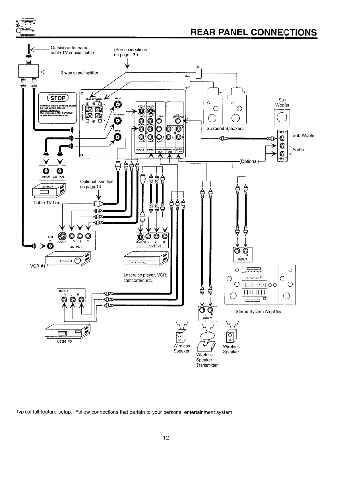
__ Outside antenna or (See connections
cable TV coaxial cable on page 13.)
_------ 2-way signal splitter
.
ooJ
INPUT OUTPUT
Optional, see tips
,_=_=- ::_ on page 1_
Cable TV box
REAR PANEL CONNECTIONS
Laserdisc player. VCR,
camcorder, etc.
VCR #2
Typ cal full feature setup. Follow connections that pertain to your personal entertainment system.
Wireless Wireless
Speaker Speaker
12
Wireless
Speaker
Transmitter
!_1 Iol
'::_ °1 I I
Stereo System Amplifier
REAR SPEAKER TERMINAL CONNECTIONS
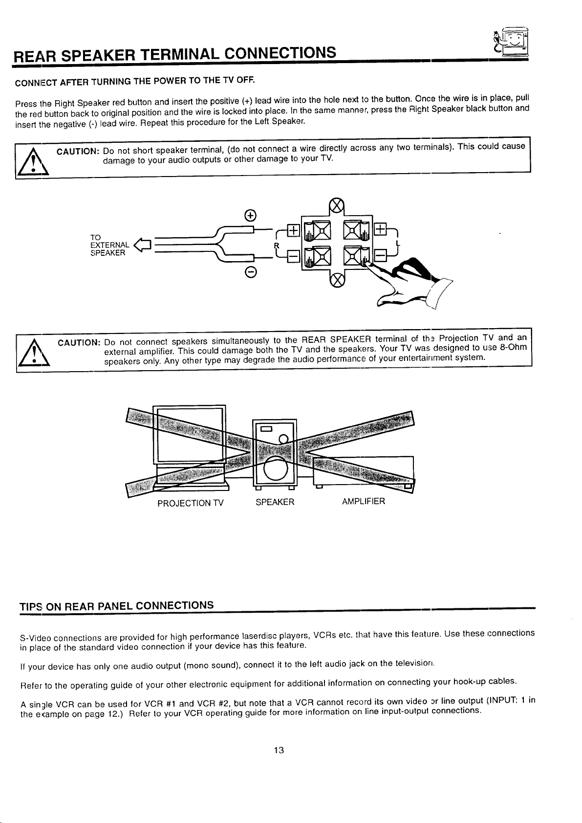
CONNI-'CT AFTER TURNING THE POWER TO THE TV OFF.
Press the Right Speaker red button and insert the positive (+) lead wire into the hole next to the button. Once the wire is in place, pull
the red button back to original position and the wire is locked into place. In the same manner, press the Right Speaker black button and
insert the negative (-) lead wire. Repeat this procedure for the Left Speaker.
l,#_e _, CAUTION: Do not short speaker terminal, (do not connect a wire directly across any two terminals). This could cause
CAUTION: Do not connect speakers simultaneously to the REAR SPEAKER terminal of th_ Projection TV and an
damage to your audio outputs or other damage to your TV.
TO
EXTERNAL<_
SPEAKER
external amplifier. This could damage both the TV and the speakers. Your TV was designed to use 8-Ohm
speakers only. Any other type may degrade the audio performance of your entertainment system.
I
PROJECTION TV SPEAKER AMPLIFIER
TIPS, ON REAR PANEL CONNECTIONS
S-Video connections are provided for high performance laserdisc players, VCRs etc. that have this feature. Use these connections
in place of the standard video connection if your device has this feature.
If your device has only one audio output (mono sound), connect it to the left audio jack on the television.
Refer to the operating guide of your other electronic equipment for additional information on connecting your hook-up cables.
A single VCR can be used for VCR #1 and VCR #2, but note that a VCR cannot record its own video or line output (INPUT: 1 in
the e:<ample on page 12.) Refer to your VCR operating guide for more information on line input-output connections.
13
-p____--
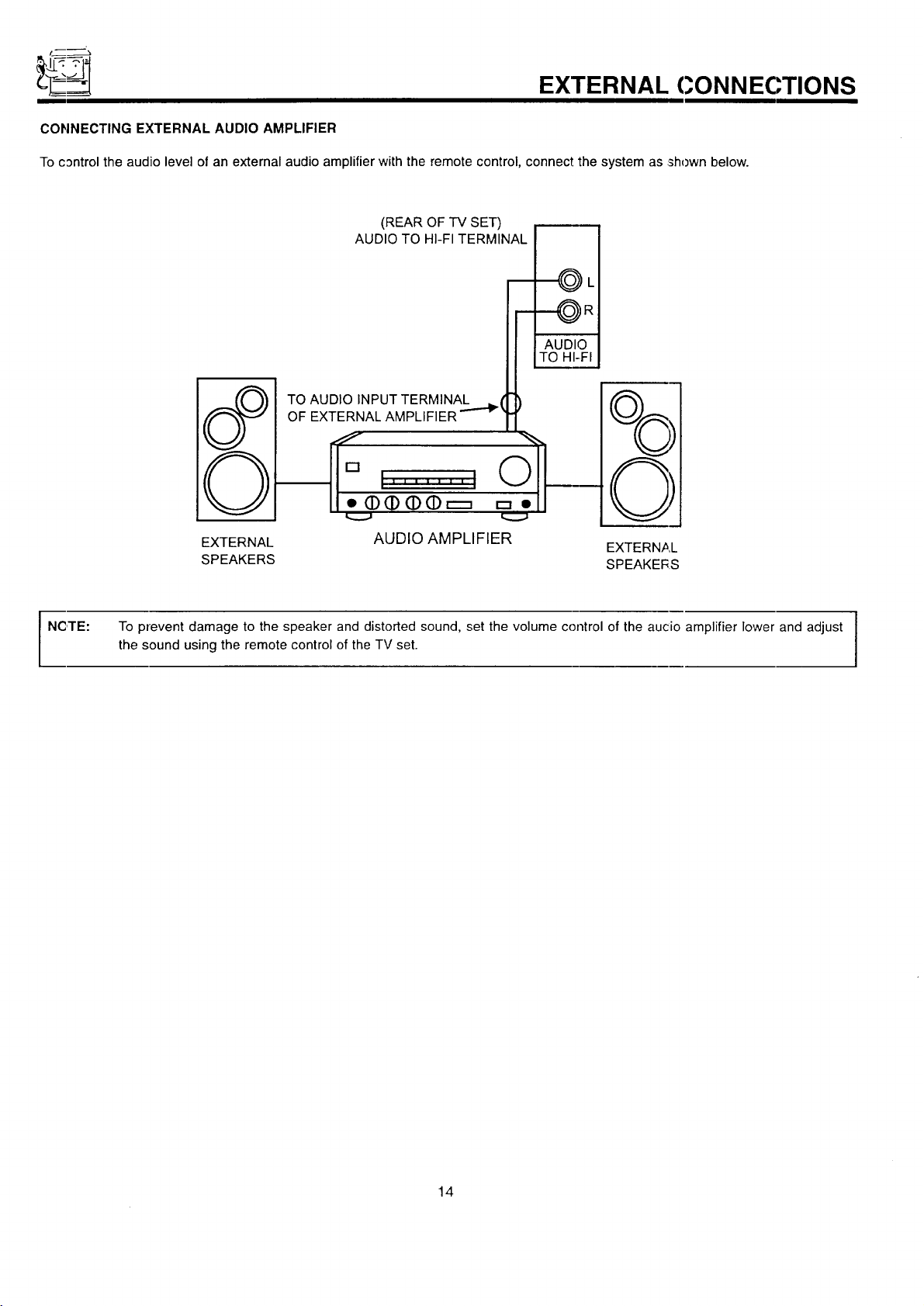
CONNECTING EXTERNAL AUDIO AMPLIFIER
To control the audio level of an external audio amplifierwith the remote control, connect the system as shown below.
(REAR OF TV SET)
AUDIO TO HI-FI TERMINAL
TO AUDIO INPUT TERMINAL _ (
OF EXTERNAL AMPLIFIER '''-'_
EXTERNAL CONNECTIONS
----_ L
NCITE:
EXTERNAL AUDIO AMPLIFIER
SPEAKERS SPEAKERS
To prevent damage to the speaker and distorted sound, set the volume control of the aucio amplifier lower and adjust I
the sound using the remote control of the TV set.
EXTERNAL
I
I
14
CONNECTING EXTERNAL VIDEO SOURCES
The exacl arrangement: you use to connect the VCR, camcorder, and laserdisc player to your TV set is dependent on the model and
features c,feach component. Check the owner's manual of each component for the location of video and audic inputs and outputs.
The following connection diagrams are offered as suggestions. However, you may need to modify them to accommodate your particular
assortment of components and features. For best performance, video and audio cables should be made trorn coaxial shielded wire.
Before Operating External Video Source
The input mode is changed every time the INPUT button ispressed as shown below. Connect an external sourc_ to the INPUT terminal,
then press the INPUT button as necessary to view the input source. (See page 23.)
INPUT MODE SELECTION ORDER
When the TV is set to VIDEO and a video signal is not received from the VlDEC) INPUT JACK on the jack panel of the
I NOTE:
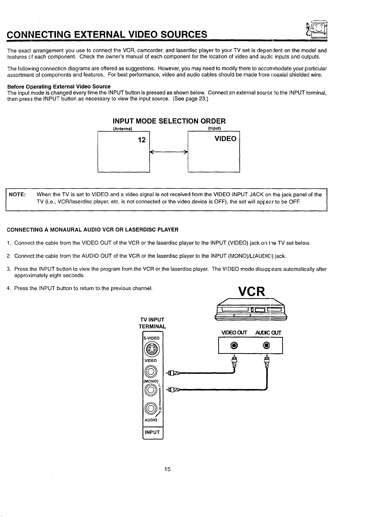
CONNECTING A MONAURAL AUDIO VCR OR LASERDISC PLAYER
1. Connect the cable lrom the VIDEO OUT of the VCR or the laserdisc player to the INPUT (VIDEO) jack on t'le TV set below.
2. Connect the cable lrom the AUDIO OUT of the VCR or the laserdisc player to the INPUT (MONO)/L(AUF)IO) jack.
3. Press the INPUT button to view the program from the VCR orthe laserdisc player. The V_I)EO mode dis_LpFears automatically after
approximately eight seconds.
4. Press the INPUT button to return to the previous channel.
TV (i.e., VCR/laserdisc player, etc. is not connected or the video device is OFF), the set will apl:,e_r to be OFF.
VCR
l ,
TV INPUT
TERMINAL
S-VIDEC
((r,_.._,
VIDEO
VIDEOOUT AUDIC OUT
[
® ® ]
I
(MONO)
\,,__J j,,
((r-_'_
\\_JW
AUDIO
I
INPU1
15
CONNECTING EXTERNAL VIDEO SOURCES
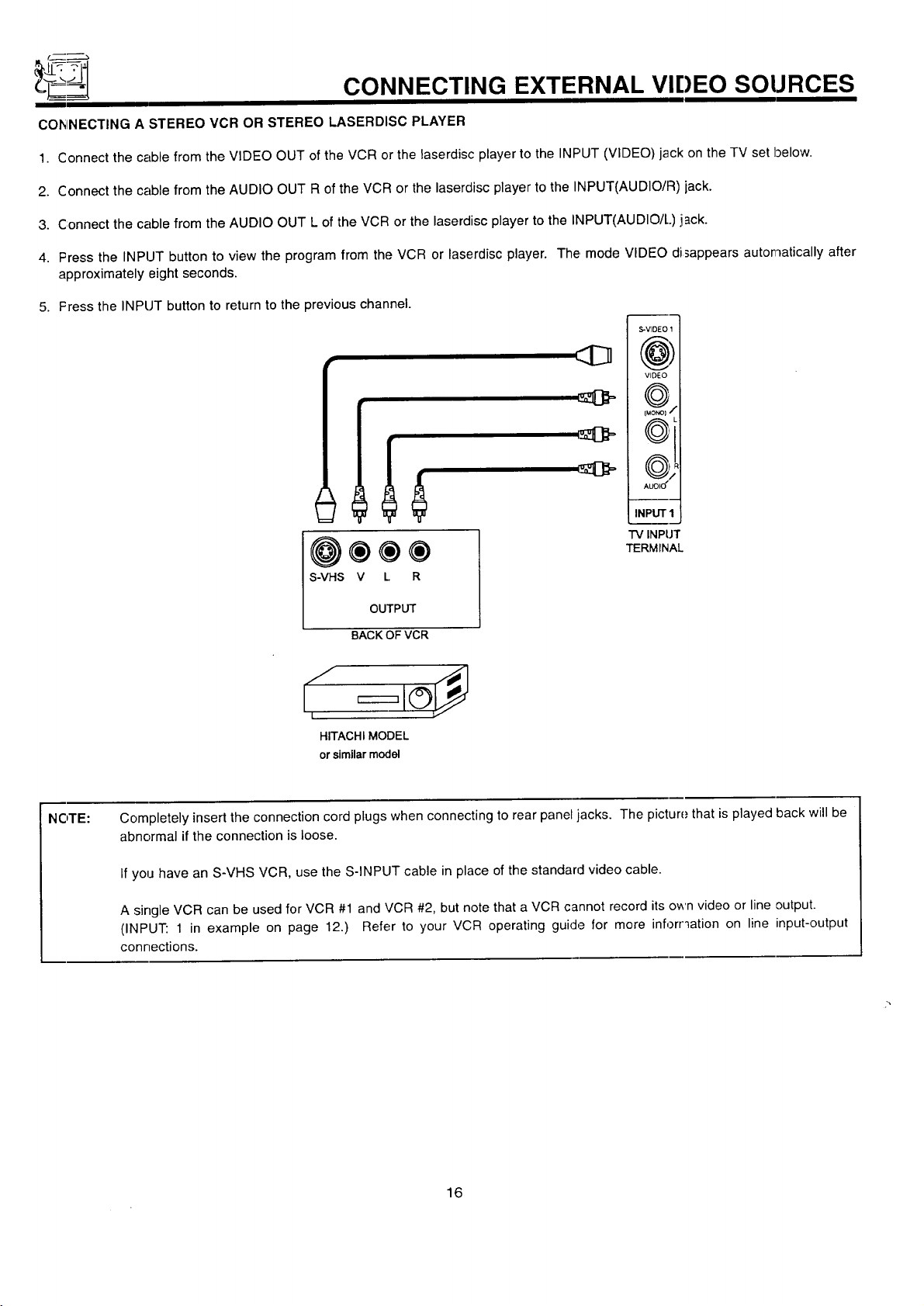
COhINECTING A STEREO VCR OR STEREO LASERDISC PLAYER
1. Connect the cable from the VIDEO OUT of the VCR or the laserdisc player to the INPUT (VIDEO) jack on the TV set below.
2. Connect the cable from the AUDIO OUT R of the VCR or the laserdisc player to the INPUT(AUDIO/R) jack.
3. Connect the cable from the AUDIO OUT L of the VCR or the laserdisc player to the INPUT(AUDIO/L) jack.
4. Press the INPUT button to view the program from the VCR or laserdisc player. The mode VIDEO disappears automatically after
approximately eight seconds.
5. Fress the INPUT button to return to the previous channel.
S-VIDEO 1
(@)
VIDEO
f...-.-_%
fuo_1 •
(_
AUL)IU
INPUT I
TV INPUT
@®®®
S-VHS V L R
TERMINAL
OUTPUT
BACK OFVCR
S I
I
HITACHI MODEL
or similar model
NOTE: Completely insert the connection cord plugs when connecting to rear panel jacks. The picture that is played back will be
abnormal if the connection is loose.
If you have an S-VHS VCR, use the S-INPUT cable in place of the standard video cable.
A single VCR can be used for VCR #1 and VCR #2, but note that a VCR cannot record its own video or line output.
(INPUT: 1 in example on page 12.) Refer to your VCR operating guide for more inforr_ation on line input-output
connections.
16
AUDIO SYSTEM SETUP
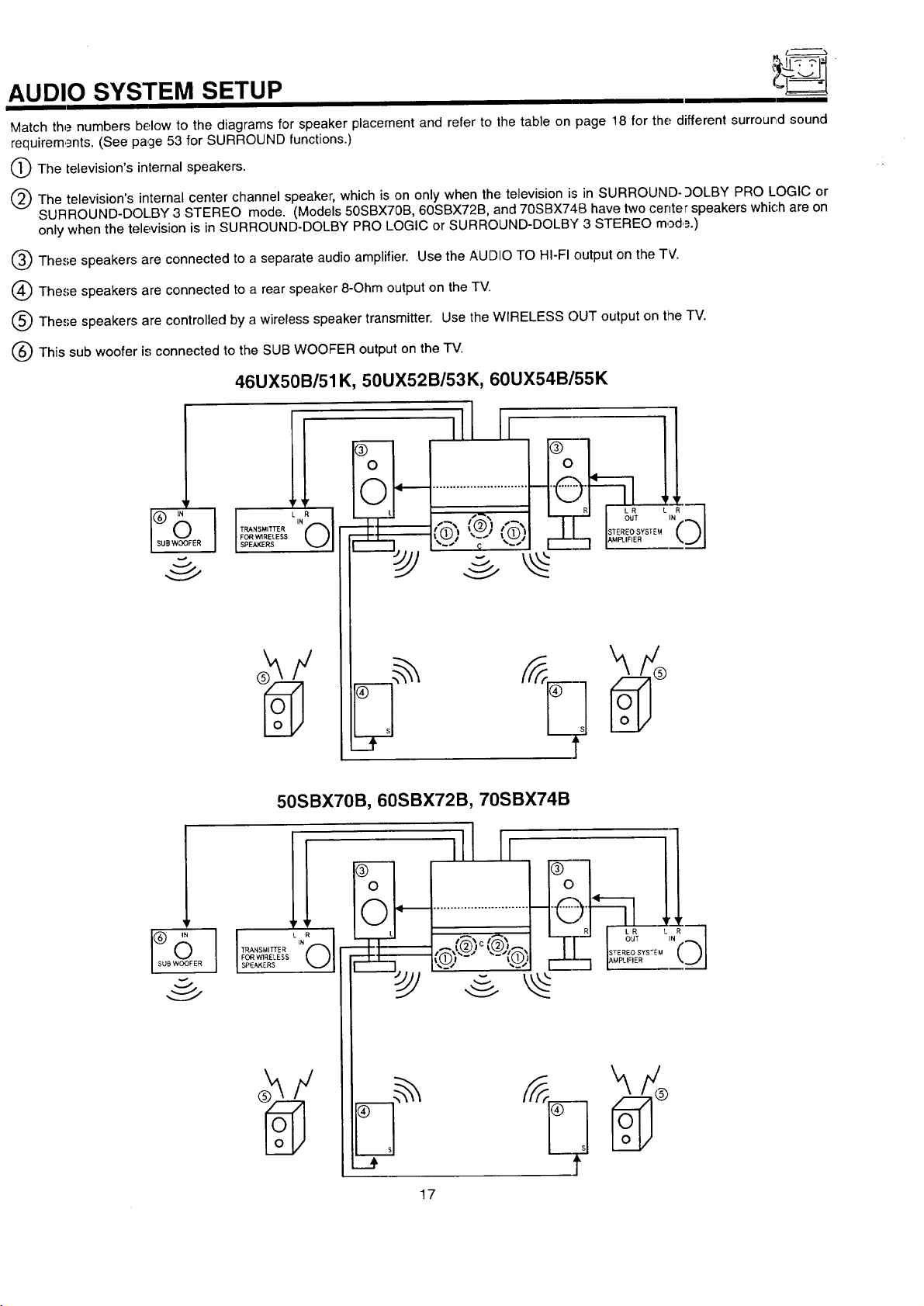
Match the numbers below to the diagrams for speaker placement and refer to the table on page 18 for the different surrour,d sound
requirem,_nts. (See page 53 for SURROUND functions.)
O The television'sinternal speakers.
(_) The television's internal center channel speaker, which is on only when the television is in SURROUND-9OLBY PRO LOGIC or
SURROUND-DOL.BY 3 STEREO mode, (Models 50SBX70B, 60SBX72B, and 70SBX740 have two center speakers which are on
only when the television is in SURROUND-DOLBY PRO LOGIC or SURROUND-DOLBY 3 STEREO mod,_.)
Q These speakers are connected to a separate audio amplifier. Use the AUDIO TO HI-FI output on the TV.
(_) These speakers are connected to a rear speaker 8-Ohm output on the TV.
Q The,';e speakers are controlled by a wireless speaker transmitter. Use the WIRELESS C)UT output on the TV.
(_ This sub woofer is connected to the SUB WOOFER output on the TV.
46UX50B/51K, 50UX52B/53K, 60UX54B/55K
50SBX70B, 60SBX72B, 70SBX74B
ill11
]!
FORWIRELESS
$PEA_ERS
17
AUDIO SYSTEM SETUP
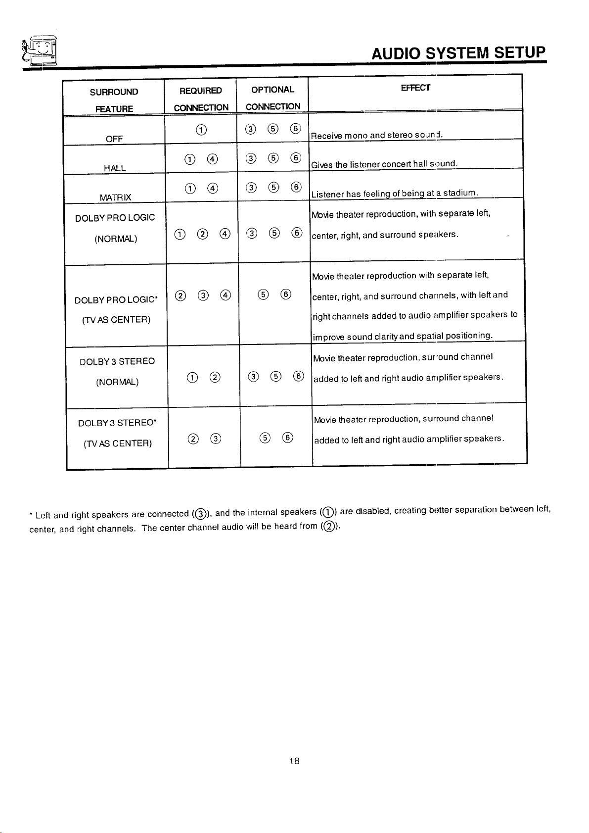
SURROUND EFFEC'I"
FEATURE
OFF Receive mono and stereo so Jn :1.
HALL Gives the listener concert hal sound.
MATRIX
DOLBY PRO LOGIC
(NORMAL)
DOLBY PRO LOGIC*
(TVAS CENTER)
DOI_BY3 STEREO
(NORMAL)
REQUIRED
CONNECTION
@
@ ®
@ @
@@®
@ @®
® @
OPTIONAL
CONNECTION
@@®
@@ @
@@@
@@®
® ®
@ @ ®
Listener has feeling of being at a stadium.
Movie theater reproduction, _ separate left,
center, right, and surround s :_eakers.
Movie theater reproduction w separate left,
center, right, and surround channels, with left and
right channels added to audi plifier speakers to
improve sound clarityand spatial positioning.
Movie theater reproduction, sur'ound channel
added to left and right audio amplifier speaker's.
DOL.BY 3 STEREO*
(-I'_fAS CENTER)
* Left and right speakers are connected ((_), and the internal speakers ((_)) are disabled, creating better separation between left,
center, and right channels. The center channel audio will be heard from ((_).
® ®
® ®
Movie theater reproduction, surround channel
added to left and right audio amplifier speakers.
18
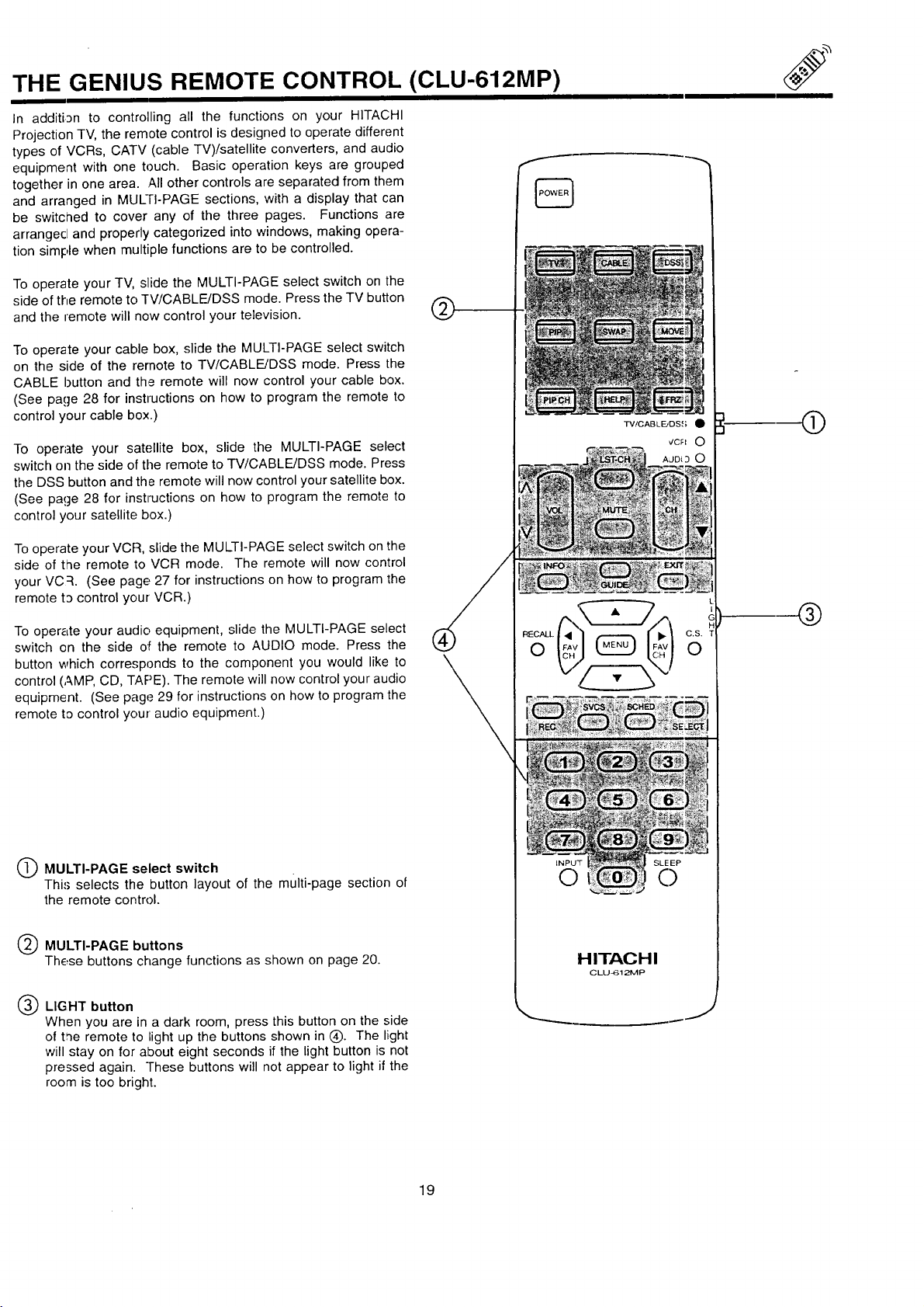
THE GENIUS REMOTE CONTROL (CLU-612MP)
In additi3n to controlling all the functions on your HITACHI
Projection TV, the remote control is designed to operate different
types of VCRs, CATV (cable TV)/satellite converters, and audio
equipment with one touch. Basic operation keys are grouped
together in one area. All other controls are separated from them
and arranged in MULrI-PAGE sections, with a display that can
be switched to cover any of the three pages. Functions are
arrangecl and properly categorized into windows, making opera-
tion simple when multiple functions are to be controlled.
To operate your TV, slide the MULTI-PAGE select switch on the
side of the remote to TV/CABLE/DSS mode. Press the TV button
and the remote will now control your television.
To operate your cable box, slide the MULTI-PAGE select switch
on the side of the remote to TV/CABLE/DSS mode. Press the
CABLE button and the remote will now control your cable box.
(See page 28 for instructions on how to program the remote to
control your cable box.)
To operate your satellite box, slide the MULTI-PAGE select
switch on the side of the remote to TV/CABLE/DSS mode. Press
the DSS button and the remote will now control your satellite box.
(See page 28 for instructions on how to program the remote to
control your satellite box.)
TV/CABLE_DS,(; •
®
Tooperate your VCR, slide the MULTI-PAGE select switch on the
side of the remote to VCR mode. The remote will now control
your VC :L (See page 27 for instructions on how to program the
remote t3 control your VCR.)
To oper_Lte your audio equipment, slide the MULTI-PAGE select
switch on the side oil the remote to AUDIO mode. Press the
button which corresponds to the component you would like to
control (,_.MP,CD, TAPE). The remote will now control your audio
equipment. (See page 29 for instructions on how to program the
remote to control your audio equipment.)
O MULTI-PAGE select switch
Thi.'; selects the button layout of the multi-page section of
the remote control.
Q MULTI-PAGE buttons
These buttons change functions as shown on page 20.
®
®
INPU_F SLE EP
C) C)
H ITAG H I
CLU_I 21VIP
Q LIGHT button
When you are in a dark room, press this button on the side
of t,ne remote to bightup the buttons shown in (_). The light
will stay on for about eight seconds if the light button is not
pressed again. These buttons will not appear to light if the
room is too bright.
J
19
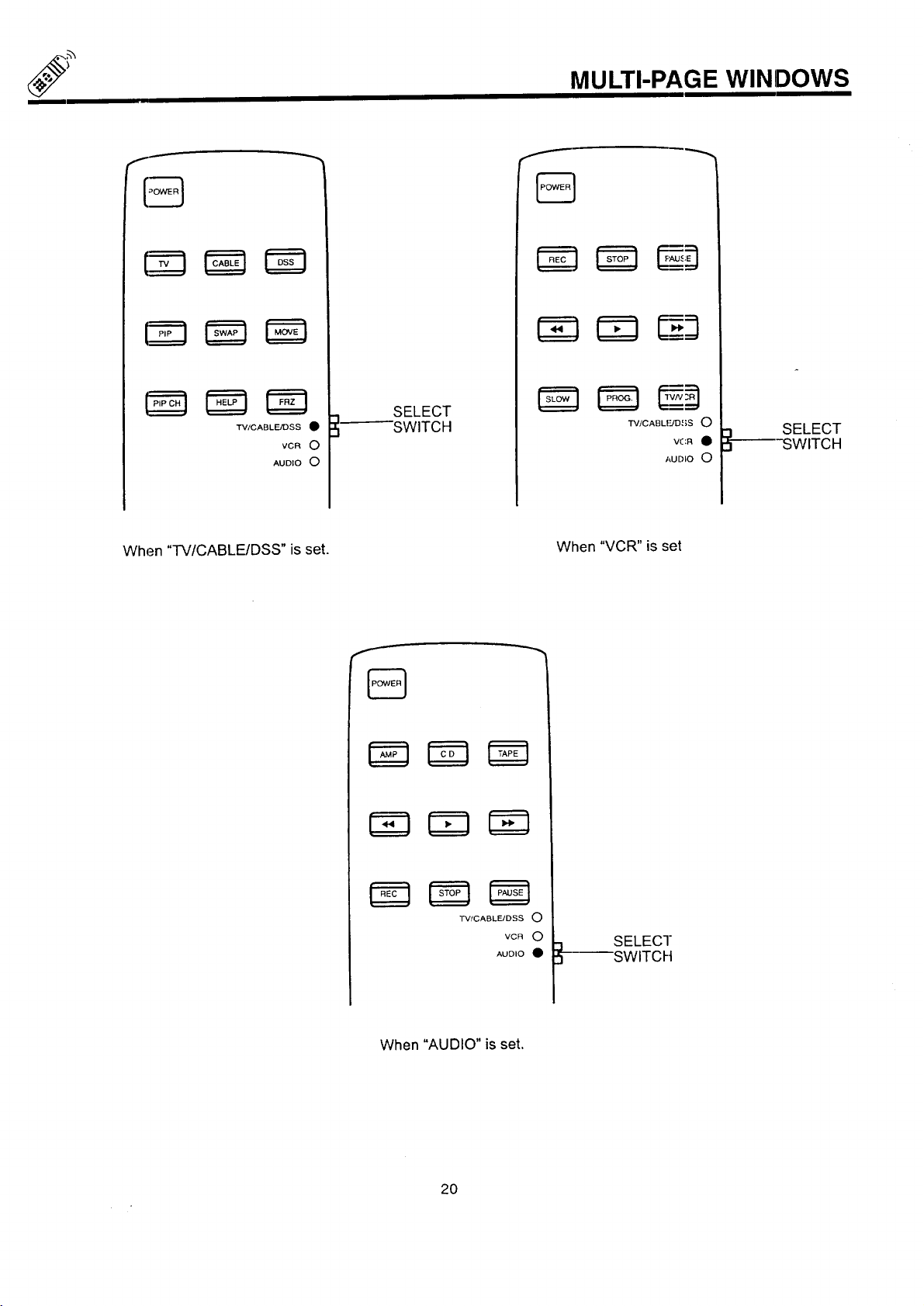
MULTI-PAGE WINDOWS
TV/CABLE/DSS •
VCR O
AUDIO O
When "TV/CABLE/DSS" is set.
SELECT
SWITCH
TV/CABLIUD ,{;S 0
AUDIO 0
When "VCR" is set
VCR •
SELECT
SWITCH
TV/CABLFJDSS O
VCR O
AUDIO •
When "AUDIO" is set.
2O
SELECT
SWITCH
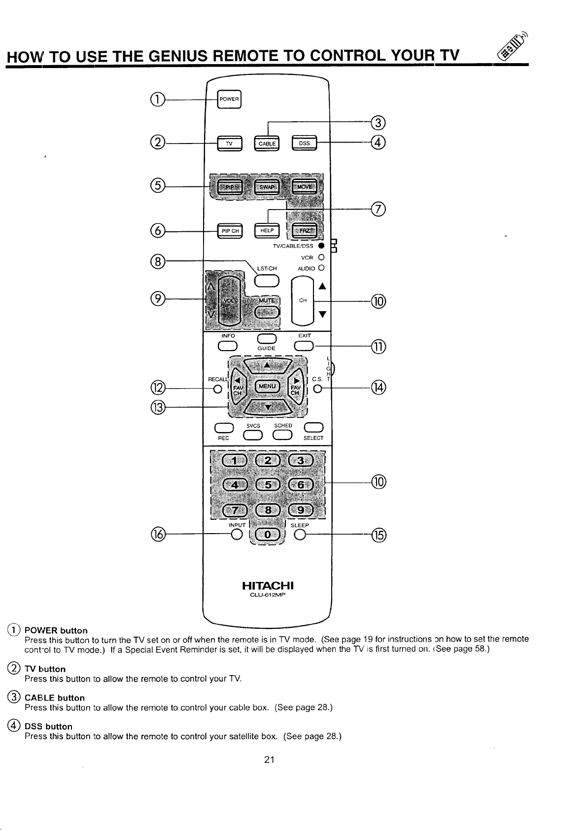
HOW TO USE THE GENIUS REMOTE TO CONTROL YOUR TV
®
@
%
TV/CABLF_JDSS •
INFO O EXIT
CZ) Gu,oECZ)
C.S. T
0
@
®
L
I
c
--®
SVCS SCHED SELC_ECT
(Z) CZD
INPUT
®
@POWER button
Press this button to turn the "IV set on or off when the remote is in -IV mode. (See page 19 for instructions an how to set the remote
cont'ol to TV mode.) If a Special Event Reminder is set, it will be displayed when the "rv is first turned on. ISee page 58.)
TV button
Press this button 1:oallow the remote to control your TV.
CAE',LE button
Press this button to allow the remote to control your cable box. (See page 28.)
0
HITACHI
CLLJ-61_P
J
DSS button
Press this button to allow the remote to control your satellite box. (See page 28.)
21
 Loading...