

Hitachi 60SX9KAP43B, 60SX8B, 50UX19KAP43, 50UX18B, 50SX6P Owner’s Manual
...
PROJECTION COLOR TV
OPERATING GUIDE
i
D
IMPORTANT SAFEGUARDS
FIRST TIME USE
THE GENIUS REMOTE
CONTROL
EASY GRAPHIC GUIDE
2-5
6-15
16-29
30 - 48
USEFUL INFORMATION
INDEX
49-55
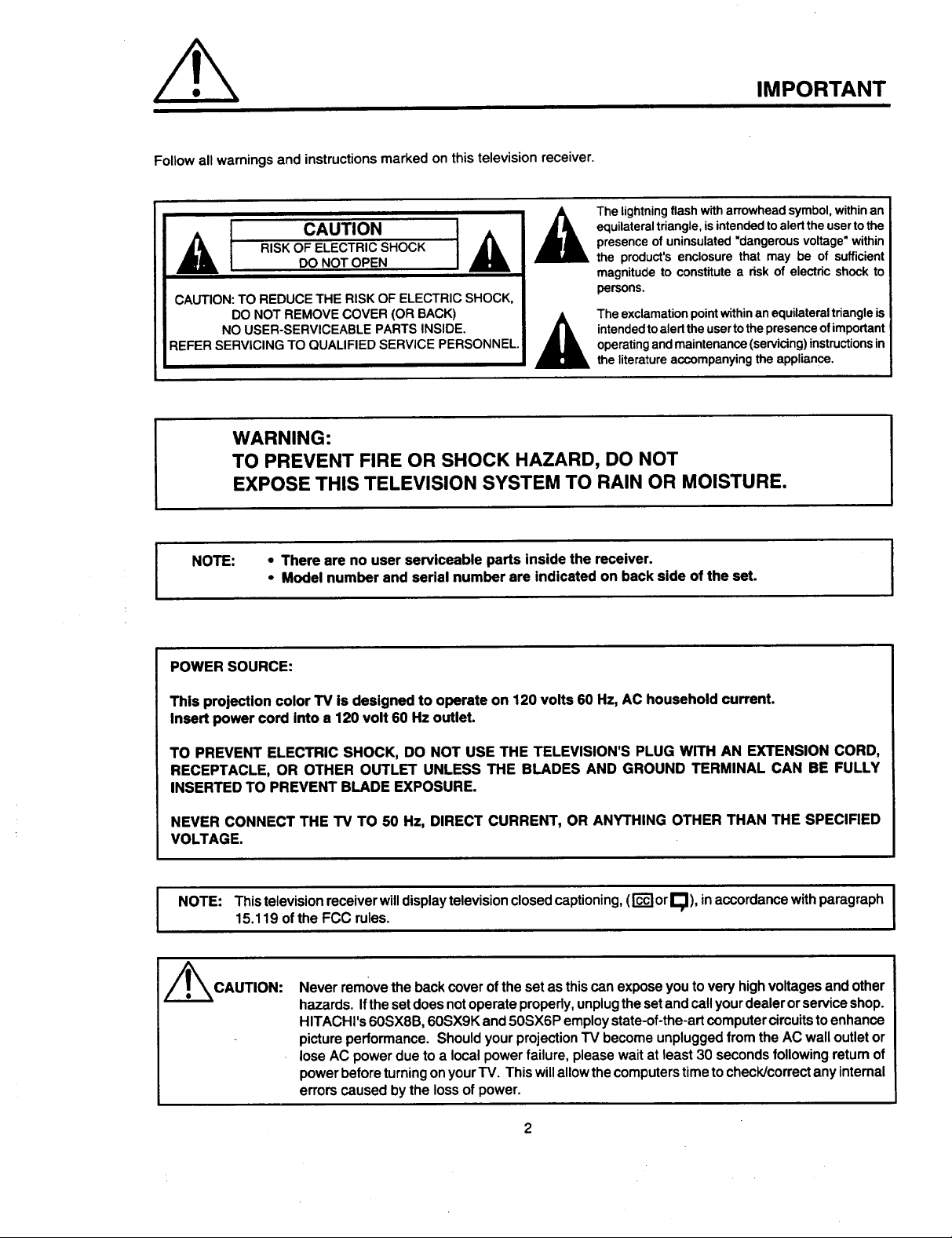
Follow all warnings and instructions marked on this television receiver.
CAUTION
RISK OF ELECTRIC SHOCK AL
DO NOT OPEN
CAUTION: TO REDUCE THE RISK OF ELECTRIC SHOCK,
DO NOT REMOVE COVER (OR BACK)
NO USER-SERVICEABLE PARTS INSIDE.
REFER SERVICING TO QUALIFIED SERVICE PERSONNEL.
A
WARNING:
TO PREVENT FIRE OR SHOCK HAZARD, DO NOT
EXPOSE THIS TELEVISION SYSTEM TO RAIN OR MOISTURE.
I
IMPORTANT
The lightning flash with arrowhead symbol, within an
equilateral triangle, isintended to alert the user to the
presence of uninsulated "dangerous voltage" within
the product's enclosure that may be of sufficient
magnitude to constitute a risk of electric shock to
persons.
The exclamationpointwithinanequilateraltriangleis
intendedtoalerttheusertothepresenceofimportant
operatingandmaintenance(servicing)instructionsin
the literatureaccompanyingthe appliance.
• There are no user serviceable parts inside the receiver.
I NOTE:
POWER SOURCE:
This projection color TV Is designed to operate on 120 volts 60 Hz, AC household current.
Insert power cord Into a 120 volt 60 Hz outlet.
TO PREVENT ELECTRIC SHOCK, DO NOT USE THE TELEVISION'S PLUG WITH AN EXTENSION CORD,
RECEPTACLE, OR OTHER OUTLET UNLESS THE BLADES AND GROUND TERMINAL CAN BE FULLY
INSERTED TO PREVENT BLADE EXPOSURE.
NEVER CONNECT THE TV TO 50 Hz, DIRECT CURRENT, OR ANYTHING OTHER THAN THE SPECIFIED
VOLTAGE.
I NOTE: This television receiver will displaytelevision closed captioning, (rc'_orE;]), inaccordance withparagraph I
/_CAUTION:
• Model number and serial number are indicated on back side of the set.
15.119 of the FCC rules.
Neverremovethebackcoverofthesetas thiscanexposeyoutoveryhighvoltagesandother
hazards.Ifthesetdoesnotoperateproperly,unplugthesetandcallyourdealerorserviceshop.
HITACHI's60SX8B,60SX9Kand50SX6P employstate-of-the-artcomputer circuitstoenhance
pictureperformance.ShouldyourprojectionTV becomeunpluggedfromthe AC walloutletor
loseAC powerduetoa localpowerfailure, pleasewaitat least 30secondsfollowing returnof
powerbeforeturningonyourTV. Thiswillallowthecomputerstimetocheck/correctanyinternal
errorscausedbythe lossof power.
I
I
I
SAFETY TIPS
IMPORTANT SAFEGUARDS
SAFETY POINTS YOU SHOULD KNOW ABOUT
YOUR HITACHI TELEVISION RECEIVER
Our reputation has been built on the quality, pedormance, and ease of service of HITACHI television receivers.
Safety is also foremost in our minds n the des gn of these un Is To help you operate these products propedy, this folder illustrates safety tips which will be of benefit
to you, Please read it carefully and apply the knowladge you obtain from it to the proper operation of your H TACH te ev s on receiver,
Please fill out your warranty card at once and mail It to HITACHI. This will enable HITACHI to notify you promptly in the improbable event that a safety problem should
be discovered in your model of product.
CAUTION:
* Read all of these instructions
* Save these instructions for later use,
* Follow all warnings and instructions marked
on the television receiver.
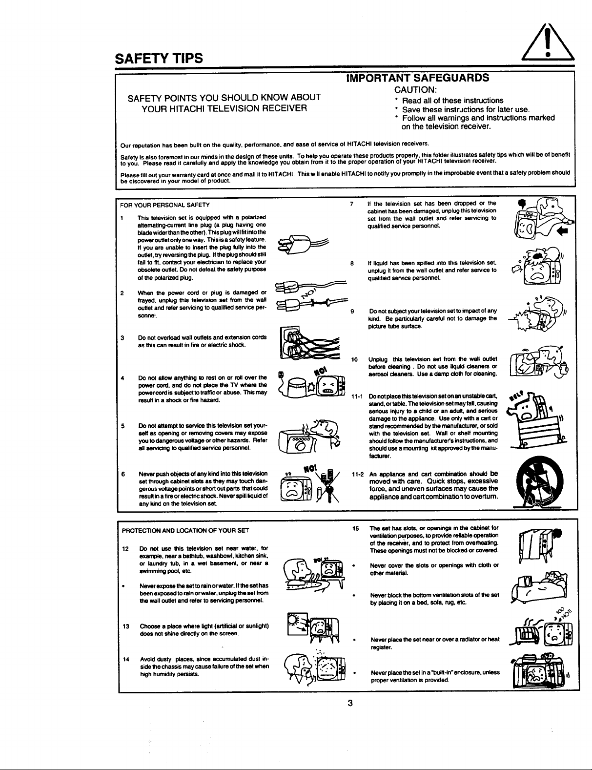
FOR YOUR PERSONAL SAFETY 7
This television set is equipped with a polarized
alternating-current line plug (a plug having one
blade wider than the other). This plug will fit into the
puwer outlet only one way. This is a safely feeture.
If you am unable to insert the plug fully into the
outlet, try reversing the plug. If the plug should still
fail to fit, contact your electrician to replace your
obsolete outlet. Do not defeat _ safety purpose
of the polarized plug.
2 When the power cord or plug is damaged or
frayed, unplug this television set from the wall
outlet and refer sarvicleg to qualified service per-
sonnol.
3 Do not overload wall outlets and extension cords
as this can result in fire or electric shock.
Do not allow anything to rest on or roll over the
pewer cord, and do on( placa the TV where the
powercordis subjectto Irafficor abuse. This rcay
result in a shock or fire hazard.
Do not attempt to service this television set your-
self as ode_ng or removing covers may axpcoe
you to clangorous voltage or other hazards, Refer
ell sarvicing to qualified service pe_l.
Never push objects of any kind into this tekP,=",=ion
sat through cabinot sfots as fr"ley may touch dan-
gerous vet!age points or short out parts thet could
result in a fire or electric shock. Never spillliquid of
any kind on the television set.
_9
If the television set has been dropped or the
cabinet has been damaged, unplug this television
set from the wall outlet and refer servicing to
qualified sarvica personnel.
If liquid has been spilled into this television set,
unplug it from the wall outlet and refer service to
qualified service personnel.
DO not subject your television set to impact of any
kind. Be particularly careful not to damage the
picture tube sudace.
Unplug this television set from the wall outlet
before cieaning. DO not use liquid cleaners or
aerosol cleaners. Usa a damp cloth for cleaning.
11-1
Do not place this tolavision set on an u_ cart,
stand, or table. The television sat may fall, causing
serious injury to a child or an adult, and serious
damage to the appliance. Use only with a cart or
stand recommended by the manufacturer, or sold
with the television saL Wall or shelf mounting
should fullow the manufacturer's instructions, and
should use a mounting kit approved by the manu-
facturer.
An appliance and cad combinationshould be
moved with care. Quick stops, excessive
force, and uneven surfaces may cause the
appliance and cart combination to overturn.
I
PROTECTION AND LOCATION OF YOUR SET
12 Do no( use this television set near water, for
example,neara bathtub,washbowl,kitchensink.
or laundrytub. in a wet basement, or near a
swimming pool,etc.
Never expose the set to rein or water. Ifthe set has
been exposed to rain or water, unplug the sat from
the wall outlet and refer to servicing personnel.
13 Choose a place where light (arlfficlel or sunlight)
does not shine directly on the screen.
14 Avoid dusty places, since accumulated dust in-
side the chassis may cause failure of the set when
high humidity persists.
15
The set has elots, or openings in the cabinet for
ventilation I_rpoees, to provide reliable operation
of _ receiver, and to protect from overheating.
These openings must not be blocked or covered.
Never cover the slots or openings with cloth or
other material.
Never block the bottom ventilation slots of the set
by placing it on a bed. sofa, rug, etc.
*.O°D'_'
Never place the set near or over a radiator or heat
":.
register.
Never place the set ina "built-in" enclosure, unless
proper ventilation is providedl
3
SAFETY TIPS
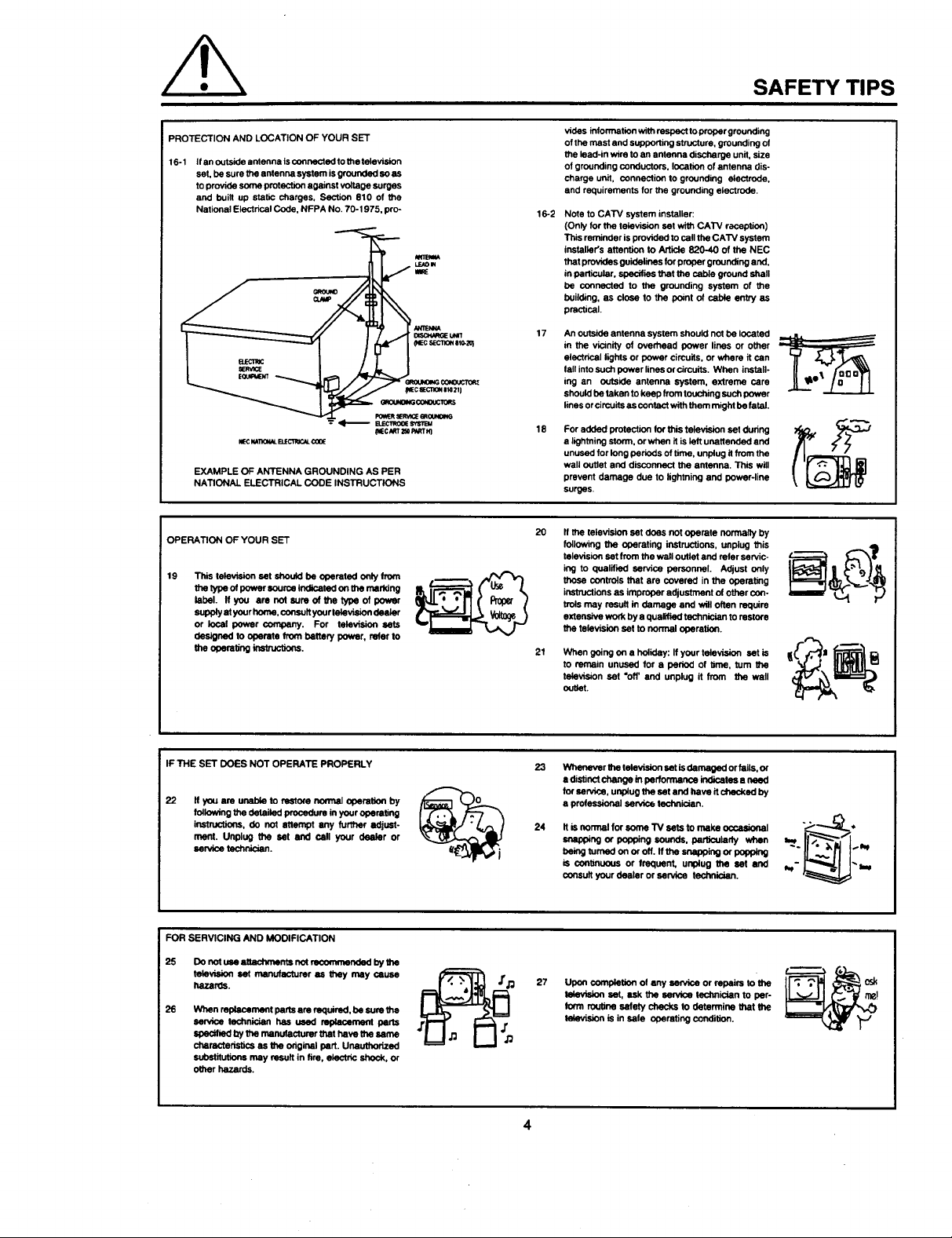
PROTECTION AND LOCATION OF YOUR SET
16-1 If an outside antenna is connected to the television
set, be sure the antenna system is grounded so as
to provide some protestion against voltage surges
and built up static charges. Section 810 of the
National Electrical Code, NFPA No. 70-1975, pro-
IKIECMTIOK_ELECl_CAL¢00E
EXAMPLE OF ANTENNA GROUNDING AS PER
NATIONAL ELECTRICAL CODE INSTRUCTIONS
OPERATION OF YOUR SET
19
This talevision set should be operated only from
tba type of power sourne indicatod on ttm marking
label. If you are not sure of Me type of power
supply at your home, consult your tolevielon deeler
or local power company. For television sets
designed to operate from battery power, refer to
the operating instruc'_ns.
_c t_T_ P_m_q
vibes information withrespect to groper grounding
of the mast end supporting structure, grounding of
the lead-in wire to an antenna discharge unit, size
of grounding conductors, location of antenna dis-
charge unit, connection to grounding electrode,
end requirements for the grounding electrode.
16-2
Note to CATV system installer:
(Only for the leisvision set with CATV reception)
This mminber is provided to call the CATV system
in,stalk}Ks attention to Article 820-40 of the NEC
that provides guidelines tor proper grounding and,
in particular, specifies that the cable ground shall
be connected to the grounding system of the
building, as close to the point of nabla entry as
practical.
17
An outside antenna system should not be located
in the vicinity of overhead power lines or other
electrical lights or power circuits, or where it can
fall into such power lines or circuits. When install-
ing an outside antenna system, extreme care
should be taken to keep from touching such power
lines or cirouits as contact with them might be fatal.
18
For added protection for this television set during
• lightning storm, or when it is left unattended end
unused for long periods of time, unplug it from the
wall outlet and disconnect the antenna. This will
prevent damage due to lightning and power-line
surges.
2O
If the television set does not operate normally by
following the operating instructions, unplug this
television set from the wall outlet and refer servic-
ing to qualified service personnel. Adjust only
those controls that are covered in the operating
insthJCtions as improper adjustment of other con-
tmls may result in damage and wilt often require
extensive work by a qualified technician to restore
the television sot to normal operation.
21
When going on a holiday: If your television set is
to remain unused for • period of time, turn the
television set "off' and unplug it from the wall
outlet.
IF THE SET DOES NOT OPERATE PROPERLY
22
If you are unable to r_tore nom_l operatioql by
foliowing the detailed procedure in your operating
instructions, do not attempt any further adjust-
merit. Unplug the set and call your dealer or
senrioe technician.
FOR SERVICING AND MODIFICATION
25 Do not use attachments net renommonded by the
television set manufacturer as they may cause
hazards.
26
When replacement paris am required, be sure the
service technician has used replacame_ parts
specified by the manufacturer that have the came
characteristi_ as the original part. Unauthorized
substitutions may result in tire, electric shock, or
other hazards.
23
Wbanever ttte felevision ,=etis damaged or fails, or
a distinct change in performanne indicates e need
for service, unplug the set and have it ctNK:ked by
a professional service technician.
24
Itis normal for seine TV eets to make ocoasional
snapping or polming sounds, particularly when
being turned on or off. If the seapping or geppmg
is continuous or frequent, unplug the set and
soneuit your dealer or service technician.
27
Upon completion of any sen_ne or repairs to the
televP_on set, ask the service technician to per-
Ion'n routine safety checks Io determine that the
television is in safe operating condition.
4
osk
PICTURE CAUTIONS
Continuous on-screen displays such as
video games, stock market quotations,
computer generated graphics, and other
fixed (non-moving) patterns can cause per-
WARNING
manent damage to projection television
receivers. Such "PATTERN BURNS" con-
stitute misuse and are NOT COVERED by
your Hitachi Factory Warranty.
When using the Picture-in-Picture function, the sub-picture should not be left permanently
in one corner of the screen or a "pattern burn" may develop over a long period of time.
This projection television receiver was intended mainly for the private viewing of programs
broadcast by TV stations and cable companies and programs from other video sources.
Public viewing may require prior authorization from the broadcaster or owner of the video
program.
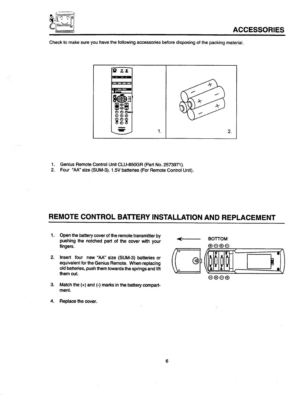
(_'_ ACCESSORIES
Check to make sure you have the following accessories before disposing of the packing material
A
, ,= ,_ ,,
OO_,-
<DOO
i
w
1. GeniusRemoteControlUnitCLU-850GR (Part No.2573971).
2. Four =AA"size(SUM-3), 1.5V batteries(For RemoteControlUnit).
1.
.
REMOTE CONTROL BATTERY INSTALLATION AND REPLACEMENT
1.
Open the battery cover of the remote transmitter by
pushing the notched part of the cover with your
fingers.
.
Insert four new =hA" size (SUM-3) batteriesor
equivalentfortheGeniusRemote. Whenreplacing
oldbatteries,pushthemtowardsthespringsand lift
themout.
.
Match the (+) and (-) marks in the battery compart-
ment.
4. Replace the cover.
J
BOTTOM
HOW TO SET UP YOUR NEW HITACHI PROJECTION TV
ANTENNA
Unless your TV isconnected to a cable "IV system or toa centralized antenna system, a good outdoor color TV antenna
is recommended for the best performance. However, if you are located in an exceptionally good signal area that is free
from interference and multiple image ghosts, an indoor antenna may be sufficient.
LOCATION
Selectan area wheresunlightorbrightindoorilluminationwillnotfalldirectlyon thepicturescreen. Also,be surethat
thelocationselectedallowsa freeflow of airto andfromtheperforatedbackcoveroftheset.
To avoidcabinet warping,cabinetcolor changes,and increasedchance of set failure,do not place the TV where
temperaturescan becomeexcessivelyhot. For example,in directsunlightor neara heatingappliance,etc.
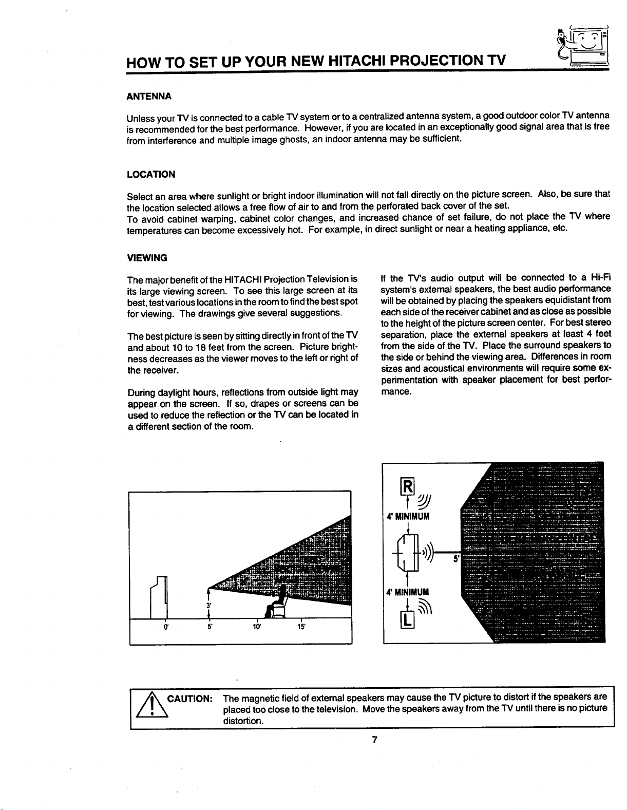
VIEWING
The majorbenefitofthe HITACHIProjectionTelevisionis
itslargeviewingscreen. To see thislarge screenat its
best,testvariouslocationsintheroomtofind thebestspot
for viewing.The drawingsgive severalsuggestions.
Thebestpictureisseenbysittingdirectlyinfrontofthe'IV
and about10 to 18 feet from the screen. Picturebright-
nessdecreasesasthe viewermovestothe leftorrightof
thereceiver.
Duringdaylighthours,reflectionsfromoutsidelightmay
appearon the screen. Ifso, drapes orscreens can be
usedtoreducethe reflectionortheTV can belocatedin
a differentsectionofthe room.
If the TV's audio outputwill be connectedto a Hi-Fi
system'sexternalspeakers,thebest audioperformance
willbeobtainedbyplacingthe speakersequidistantfrom
eachsideofthereceivercabinetandascloseaspossible
tothe heightofthepicturescreencenter. For beststereo
separation,place the externalspeakersat least 4 feet
from thesideofthe TV. Place thesurroundspeakersto
thesideor behindthe viewingarea. Differencesin room
sizesand acoustical environmentswillrequiresomeex-
perimentationwithspeaker placementfor best perfor-
mance.
4' MINIMUM
I _CAUTION:
4'MINIMUM
i
15'
The magnetic field of extemal speakers may cause the TV picture to distort if the speakers are
placed too close to the television. Move the speakers away from the TV untilthere is no picture
distortion.
7
HOOK-UP CABLES AND CONNECTORS
Most video/audio connections between components can
be made with shielded video and audio cables that have
phono connectors. For best performance, video cables
should use 75-ohm coaxial shielded wire. Cables can be
purchased from most stores that sell audio/video prod-
ucts. Below are illustrationsand names of common con-
nectors.
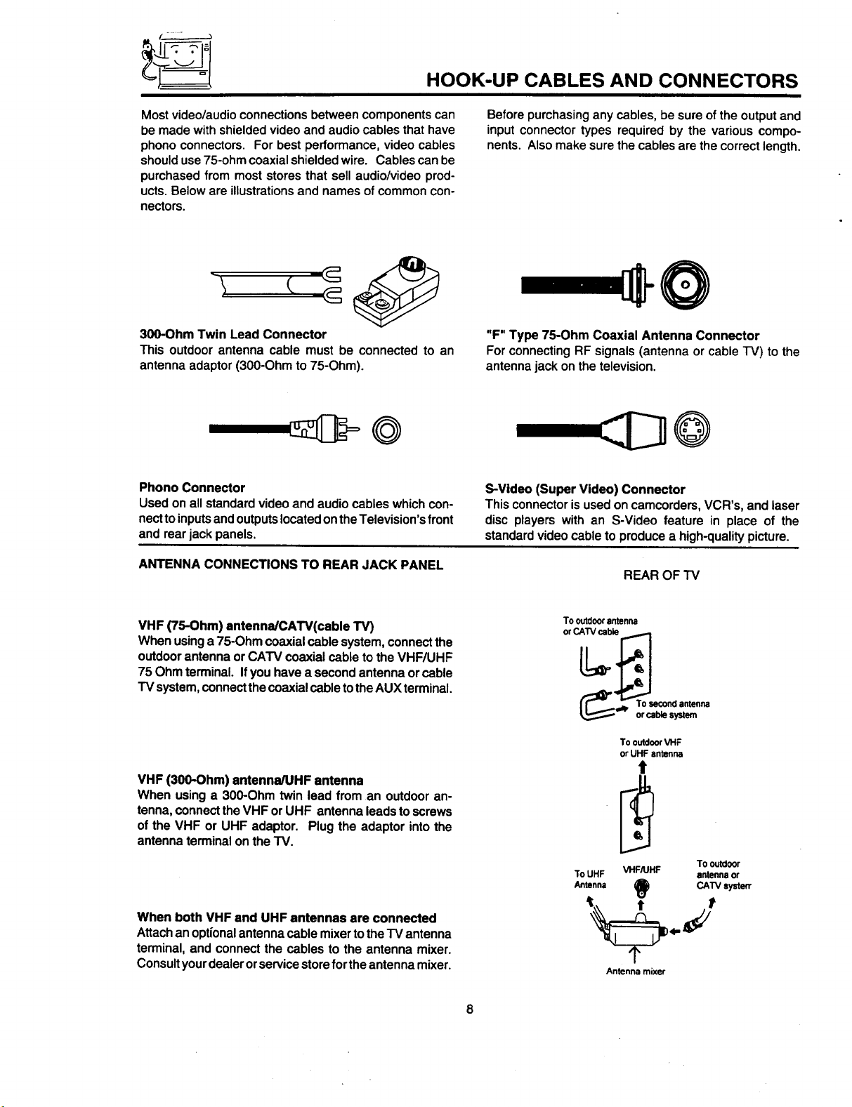
300-Ohm Twin Lead Connector
This outdoorantenna cable must be connectedto an
antennaadaptor(300-Ohmto 75-Ohm).
Phono Connector
Used onallstandardvideoand audiocableswhichcon-
necttoinputsandoutputslocatedontheTelevision'sfront
and rearjackpanels.
Before purchasing any cables, be sure of the output and
input connector types required by the various compo-
nents. Also make sure the cables are the correct length.
"F" Type 75-Ohm Coaxial Antenna Connector
ForconnectingRF signals(antennaor cable"I-V)to the
antennajackon thetelevision.
@
S-Video (Super Video) Connector
This connectorisusedoncamcorders,VCR's, andlaser
disc players with an S-Video feature in place of the
standardvideo cableto producea high-qualitypicture.
ANTENNA CONNECTIONS TO REAR JACK PANEL
VHF (75-Ohm) antenna/CATV(cable TV)
When usinga 75-Ohmcoaxialcablesystem,connectthe
outdoorantennaorCATV coaxialcable tothe VHF/UHF
75 Ohmterminal.If youhavea secondantennaorcable
TVsystem,connectthecoaxial cabletotheAUXterminal.
VHF (300-Ohm) antenna/UHF antenna
When usinga 300-Ohm twin lead from an outdooran-
tenna,connecttheVHF orUHF antennaleadstoscrews
of the VHF orUHF adaptor. Plugthe adaptorintothe
antennaterminalonthe TV.
When both VHF and UHFantennas are connected
Attachan optionalantennacable mixertothe TVantenna
terminal,and connectthe cablesto the antenna mixer.
Consultyourdealerorservicestorefor theantennamixer.
REAR OF'IV
To outdoorantenna
orCAI"V_ble_
To outdoorVHF
or UHF antenna
To UHF VHF/UHF antenna or
Antenna O CATV systerr
Antenna mixer
To outdoor
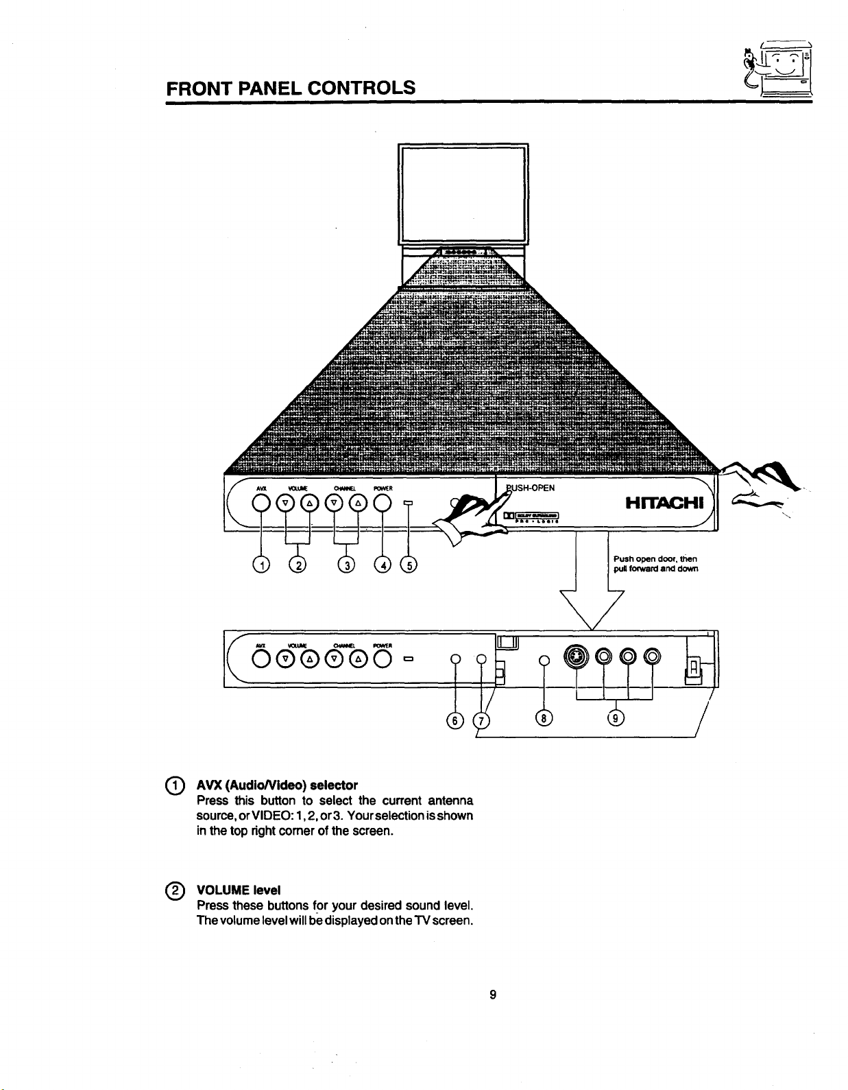
FRONT PANEL CONTROLS
AVX (AudioNideo) selector
(9
Press this button to select the current antenna
source,orVIDEO: 1,2, or3. Yourselectionisshown
inthetop rightcomerofthe screen.
@ VOLUME level
Press these buttons for your desired sound level.
The volume level will be displayed on the TV screen.
pu_fo_ard and down
/
FRONT PANEL CONTROLS
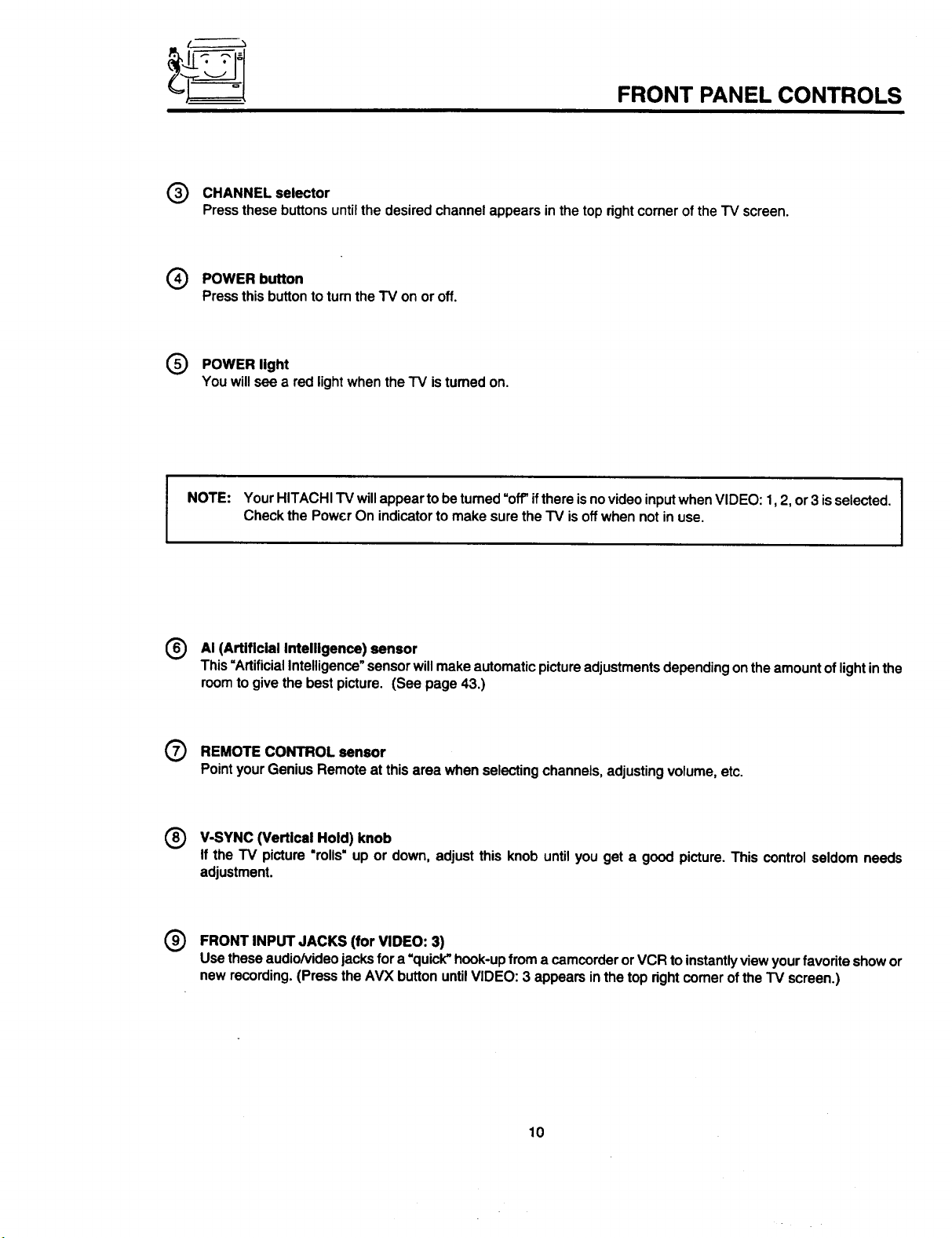
O CHANNEL selector
Pressthese buttonsuntilthe desiredchannelappearsinthetoprightcornerofthe TV screen.
(_ POWER button
Pressthisbuttonto turnthe TV on or off.
Q POWER light
You will see a red light when the "IV is tumed on.
NOTE: YourHITACHI TVwillappeartobe tumed"off'ifthereisnovideoinputwhenVIDEO:1,2, or3 isselected.
CheckthePowerOn indicatorto makesuretheTV isoffwhennotin use.
(_ AI (Artificial Intelligence) sensor
This=ArtificialIntelligence"sensorwillmakeautomaticpictureadjustmentsdependingontheamountoflightinthe
roomto givethebestpicture. (See page 43.)
(_) REMOTECONTROL sensor
PointyourGeniusRemoteat thisareawhenselectingchannels,adjustingvolume,etc.
(_ V-SYNC (Vertical Hold) knob
If the TV picture"rolls=up or down,adjustthis knob untilyouget a good picture.This controlseldomneeds
adjustment.
O FRONT INPUT JACKS (for VIDEO: 3)
Use these audio/video jacks for a =quick"hook-up from a camcorder or VCR to instantlyview your favorite show or
new recording. (Press the AVX button until VIDEO: 3 appears inthe top right comer of the TV screen,)
10
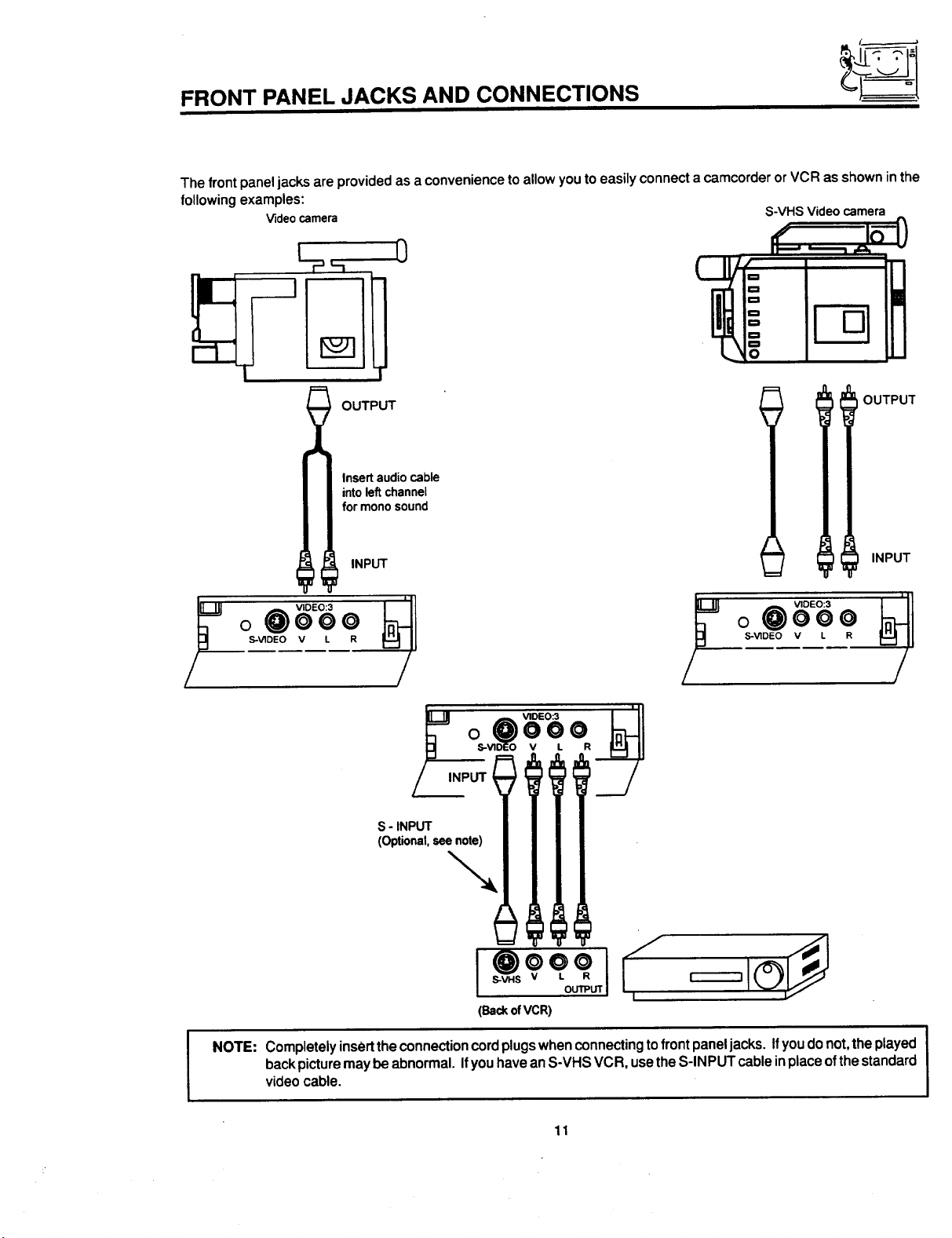
FRONT PANEL JACKS AND CONNECTIONS
The front panel jacks are provided as a convenience to allow you to easily connect a camcorder or VCR as shown in the
following examples:
Videocamera
S-VHS Video camera
0
c=
_=
O
OUTPUT
Insertaudiocable
intoleftchannel
formonosound
INPUT
o 0000
S-V1DEO V L R
y jo .oEo 3
VIDEO:3 _1
;I o @ooo
S-VIDEO V L R
OUTPUT
INPUT
I
NOTE: Completely insert the connection cord plugs when connecting to front panel jacks. Ifyou do not, the played
back picture may be abnormal. Ifyou have an S-VHS VCR, use the S-INPUT cable inplace of the standard
video cable.
11
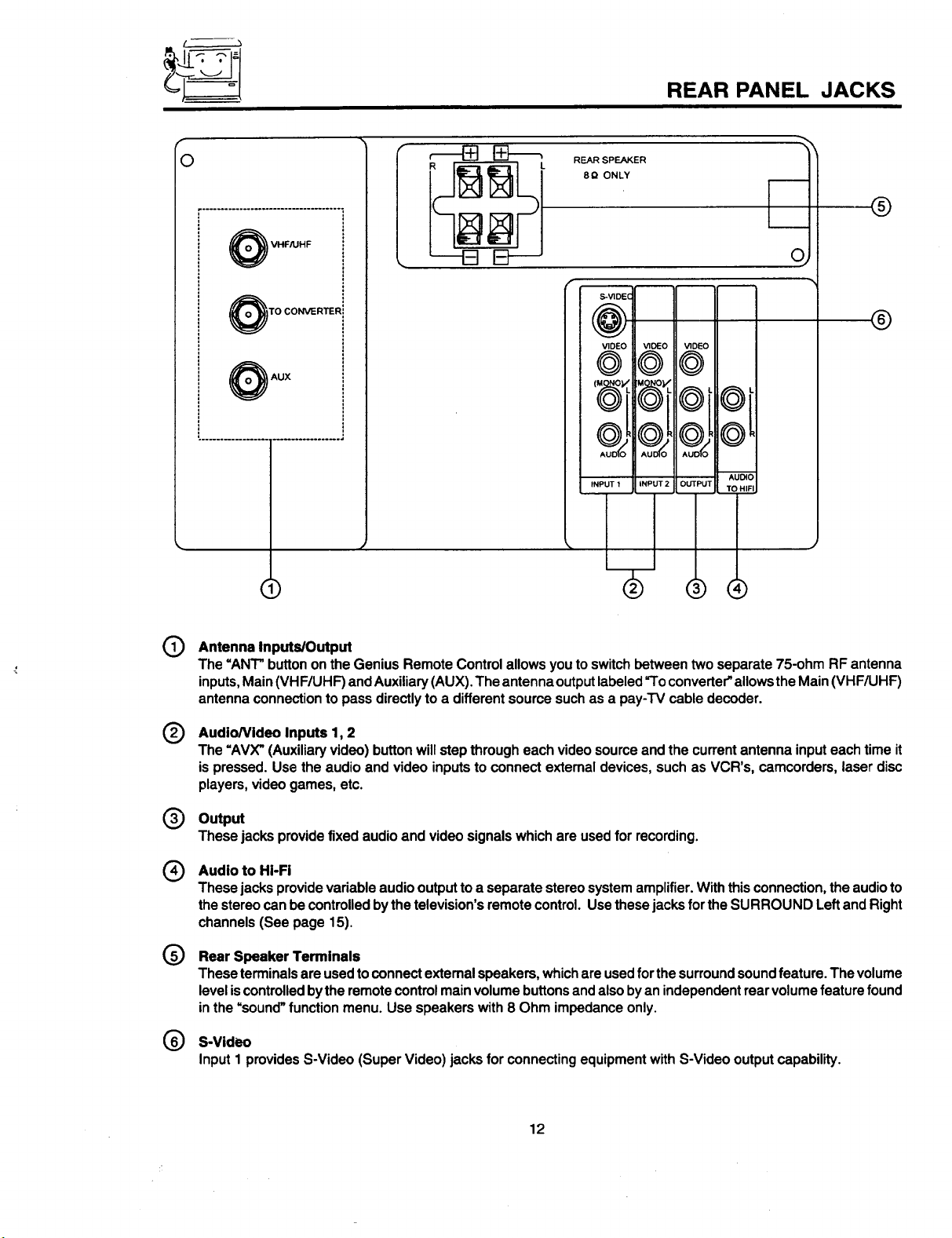
REAR PANEL JACKS
r
O
L
REAR SPEAKER
8_ ONLY
r...................................
VHF/UHF
TO CONVERTER=
F-
o_
olloll
@
AUX
I
()
(D
Antenna Inputs/Output
The =ANT"buttononthe GeniusRemoteControlallowsyouto switchbetweentwo separate75-ohm RFantenna
inputs,Main(VHF/UHF)andAuxiliary(AUX).The antennaoutputlabeled=Toconverter"allowsthe Main(VHF/UHF)
antennaconnectionto passdirectlyto a differentsourcesuchas a pay-TVcabledecoder.
IDIO
HIFI
,)
®
®
®
Audio/Video Inputs 1, 2
The "AVX"(Auxiliaryvideo)buttonwillstepthrougheach videosourceand the currentantennainputeachtimeit
is pressed.Use the audioandvideo inputstoconnectexternaldevices,suchas VCR's, camcorders, laserdisc
players,videogames,etc.
Output
®
Thesejacksprovidefixed audioand videosignalswhichare usedfor recording.
Audio to HI-Fi
®
These jacksprovidevariableaudiooutputtoa separatestereosystemamplifier.Withthis connection,the audioto
thestereocanbecontrolledbythetelevision'sremotecontrel.Usethesejacksfor the SURROUND LeftandRight
channels(See page 15).
®
Rear Speaker Terminals
Theseterminalsareusedtoconnectextemalspeakers,whichare usedforthesurroundsoundfeature.Thevolume
leveliscontrolledbythe remotecontrolmainvolumebuttonsandalsobyanindependentrearvolumefeature found
in the=sound"function menu. Use speakerswith8 Ohm impedanceonly.
S-Video
®
Input 1 provides S-Video (Super Video) jacks for connecting equipment with S-Video output capability.
12
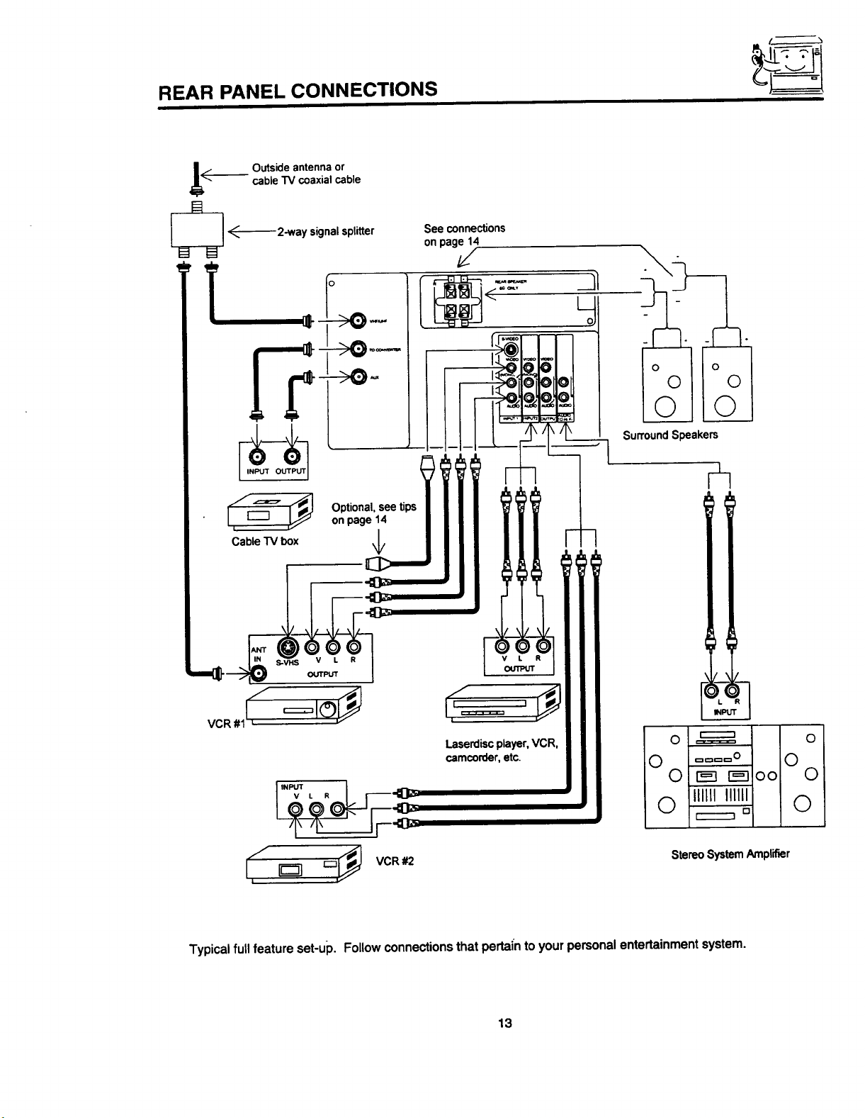
REAR PANEL CONNECTIONS
cable TV coaxial cable
._ Outside antenna or
_ _------2-way signal splitter
[/_:_, _ Optional, see tips
Cable TV box \1/
on page 14
See connections
on page 14
v
/
[____o,O<___'N_'"I r--"_
StereoSystemAmplifier
;° vcR,2
Typical full feature set-up. Followconnectionsthat pertai'ntoyourpersonalentertainmentsystem.
13
0
iO
0
0
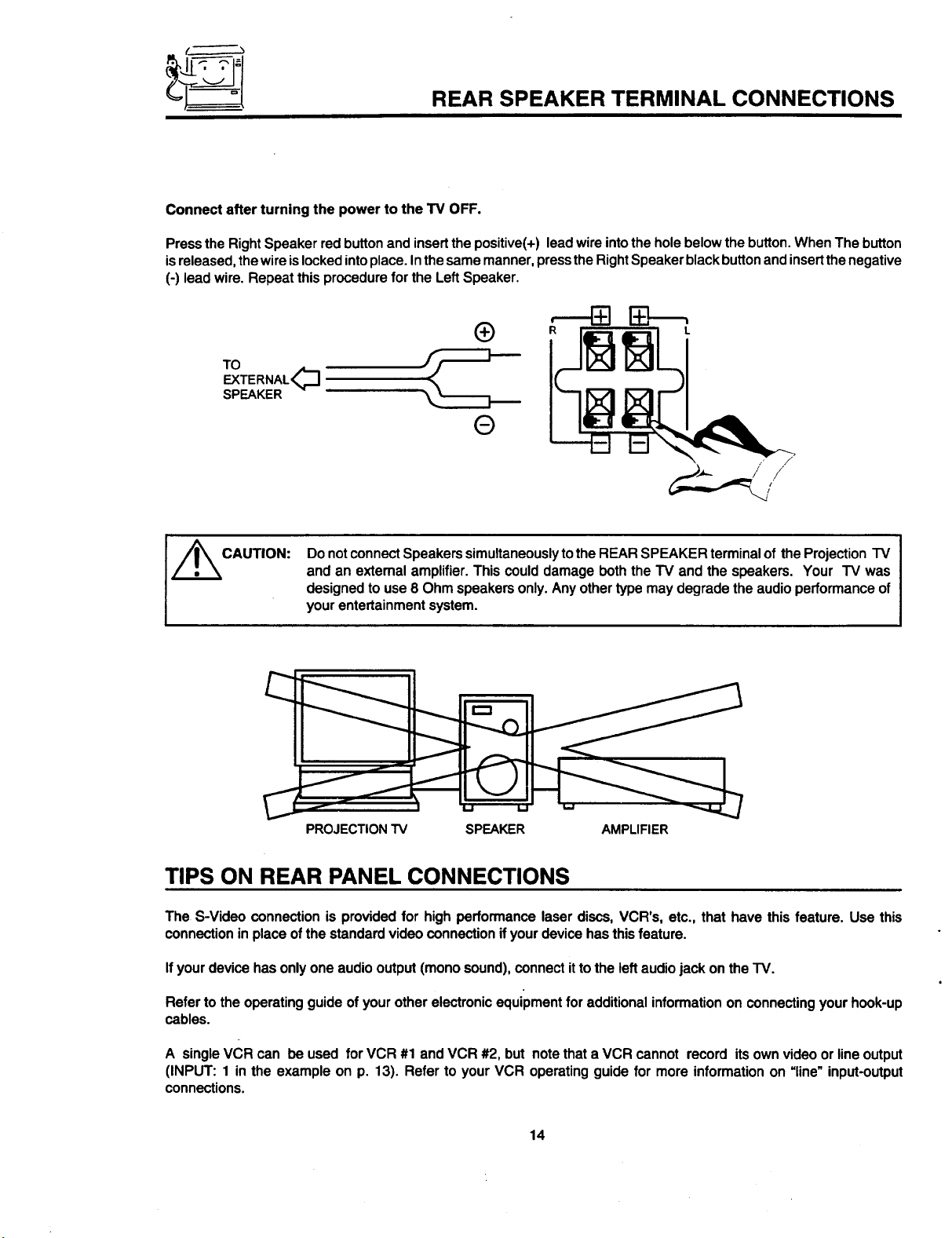
REAR SPEAKER TERMINAL CONNECTIONS
Connect after turning the power to the TV OFF.
Press the Right Speaker red button and insertthe positive(+) lead wire intothe hole below the button. When The button
is released, the wire islocked intoplace. In the same manner, press the Right Speaker black buttonand insertthe negative
(-) lead wire. Repeat this procedure for the Left Speaker.
TO
EXTERNAL<_
SPEAKER
/_CAUTION:
DonotconnectSpeakerssimultaneouslytothe REARSPEAKERterminal of theProjectionTV
and an extemalamplifier.Thiscoulddamage boththe"IV and the speakers. Your TV was
designedto use8 Ohmspeakersonly.Anyothertypemaydegradetheaudioperformanceof
yourentertainmentsystem.
PROJECTIONTV SPEAKER AMPLIFIER
TIPS ON REAR PANEL CONNECTIONS
The S-Video connectionis providedfor high performancelaserdiscs,VCR's, etc., that have this feature.Use this
connectionin placeofthe standardvideo connection ifyourdevicehasthisfeature.
Ifyourdevicehasonlyone audiooutput(monosound),connectittothe leftaudiojack ontheTV.
Referto theoperatingguideof yourotherelectronicequipmentfor additionalinformationon connectingyourhook-up
cables.
A singleVCRcan be used for VCR #1 and VCR#2, but notethata VCR cannot record itsownvideoorlineoutput
(INPUT: 1 in the example on p. 13). Refer to your VCR operatingguide for more informationon =line"input-output
connections.
14
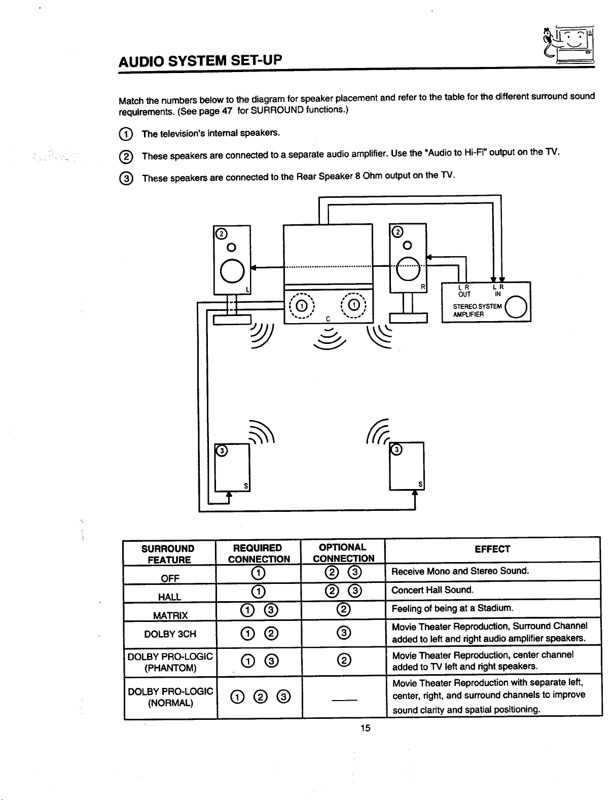
AUDIO SYSTEM SET-UP
Match the numbers below to the diagram for speaker placement and refer to the table for the different surround sound
requirements. (See page 47 for SURROUND functions.)
The television'sintemal speakers.
, :•..
These speakersareconnectedto aseparateaudioamplifier.Usethe "Audioto Hi-Fi"outputonthe TV.
O These speakersareconnectedto theRear Speaker8 Ohmoutputonthe TV.
SURROUND
FEATURE
OFF
HALL
MATRIX
DOLBY 3CH
DOLBY PRO-LOGIC
(PHANTOM)
DOLBY PRO-LOGIC
(NORMAL)
REQUIRED
CONNECTION
CONNEXION
®
®
@®
@®
@® ®
O®®
OP_ONAL
®®
®®
®
®
EFFECT
ReceiveMonoandStereoSound.
ConcertHallSound.
Feeling of being at a Stadium.
Movie Theater Reproduction, Surround Channel
added to left and right audio amplifier speakers.
Movie Theater Reproduction, center channel
added to "IV left and right speakers.
Movie Theater Reproduction with separate left,
center, right, and surround channels to improve
sound clarity and spatial positioning.
15
j
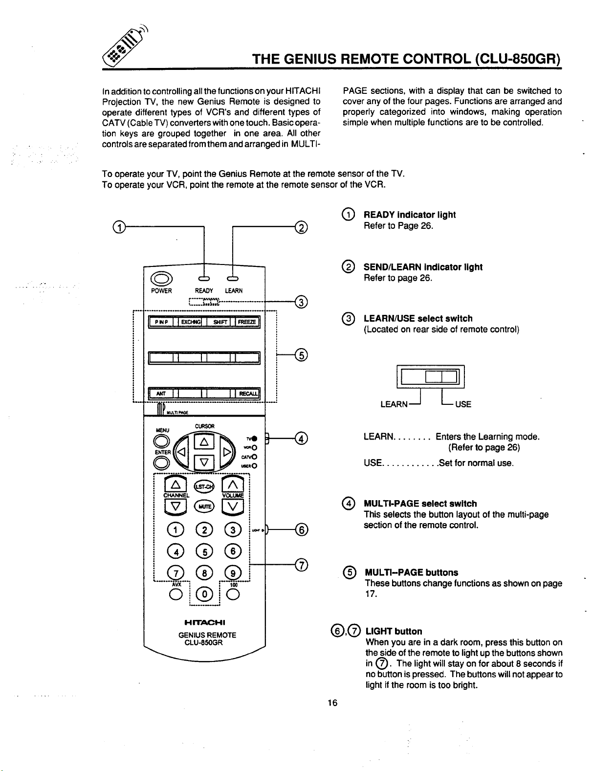
THE GENIUS REMOTE CONTROL (CLU-850GR)
Inadditiontocontrolling allthefunctionsonyour HITACHI
ProjectionTV, the new GeniusRemote is designedto
operatedifferenttypes of VCR's and differenttypesof
CATV(CableTV) converterswithonetouch.Basicopera-
tionkeys are groupedtogether in one area. All other
controlsareseparatedfrom themandarrangedin MULTI-
To operateyour TV, point the GeniusRemote at the remote sensorof the TV.
To operateyour VCR, pointtheremoteat the remotesensoroftheVCR.
o
POWER
t ................................. °°_,
!1P.P I IExc._l I ='_1 I._EEI!
READY LEARN
PAGE sections, with a display that can be switched to
cover any of the four pages. Functions are arranged and
properly categorized into windows, making operation
simple when multiple functions are to be controlled.
O READY indicator light
Referto Page26.
Q SEND/LEARN indicator light
Refer to page 26.
Q LEARN/USE select switch
(Locatedon rearside ofremotecontrol)
t1 ii ii ii II
.....mP.:::::...............................
CURSOR
CHANNEL VOLUME
Q®
Q
(i)
®®i
Q
®
AVX
©
®o
H rr_H I
GENIUS REMOTE
CLU-850GR
100
(_),Q LIGHT button
16
LEARN........ EnterstheLearningmode.
(Refertopage 26)
USE............ Set for normaluse.
Q MULTI-PAGE select switch
This selects the button layout of the multi-page
section of the remote control.
O ULTI-PAGE buttons
These buttons change functions as shown on page
17.
Whenyou are in a dark room,press thisbuttonon
thesideof theremotetolightupthebuttonsshown
in (_. The lightwillstayonfor about8secondsif
nobuttonis pressed.Thebuttonswillnotappearto
lightifthe roomistoobright.
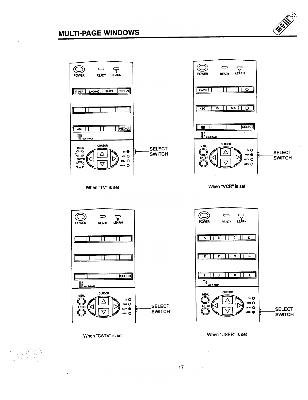
MULTI-PAGE WINDOWS
POWER READY LEARN
_-.
I _ I I tl I IRECALq!
CURSOR
When"TV"is set
SELECT
SWITCH
POWER RF_DY LEARN
!lTvmNI II II 0 I1
!1<4 II _" II _'_'11 0 I1
Itll SELECT !
MENU
CURSOR
_e
When"VCR" isset
SELECT
SWITCH
POWER READY LEARN
POWER READY LEARN
[ A II a II c II o i
I E II F II G II " IJ
!1 II II I ISEI-EC_I
I ' II " II K II L Ii
I_I..,.,,.'r,,,_
c_
.o
_wO
'_0
When"CATV" isset When"USER" isset
SELECT
SWITCH
17
SELECT
SWITCH
 Loading...