


Hitachi 50SB User Manual
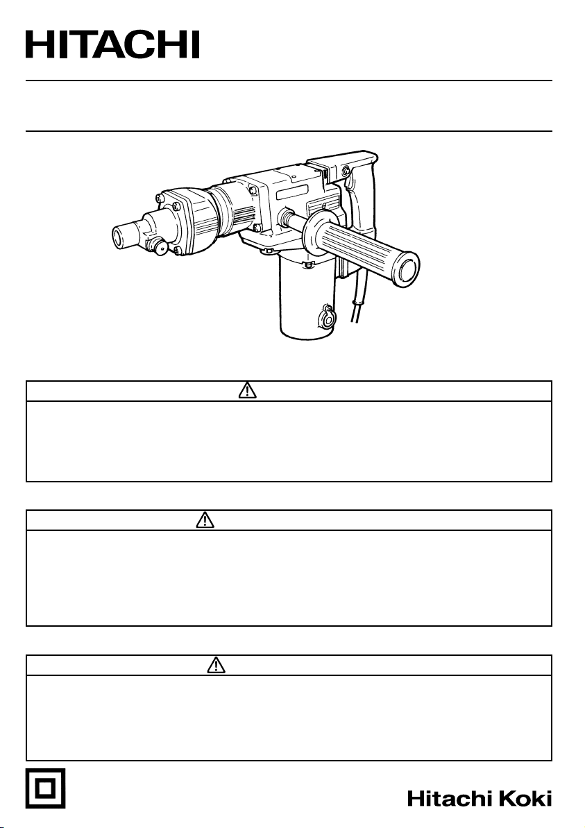
Model Rotary Hammer
Modèle Marteau rotatif
Modelo Martillo perforador
DH 50SB
SAFETY INSTRUCTIONS AND INSTRUCTION MANUAL
WARNING
IMPROPER OR UNSAFE use of this power tool can result in death or serious bodily
injury!
This manual contains important information about product safety. Please read and
understand this manual BEFORE operating the power tool. Please keep this manual
available for other users and owners before they use the power tool. This manual should
be stored in safe place.
INSTRUCTIONS DE SECURITE ET MODE D’EMPLOI
AVERTISSEMENT
Une utilisation INCORRECTE OU DANGEREUSE de cet outil motorisé peut entraîner la
mort ou de sérieuses blessures corporelles!
Ce mode d’emploi contient d’importantes informations à propos de la sécurité de ce
produit. Prière de lire et de comprendre ce mode d’emploi AVANT d’utiliser l’outil
motorisé. Garder ce mode d’emploi à la disponibilité des autres utilisateurs et propriétaires
avant qu’ils utilisent l’outil motorisé. Ce mode d’emploi doit être conservé dans un
endroit sûr.
INSTRUCCIONES DE SEGURIDAD Y MANUAL DE INSTRUCCIONES
ADVERTENCIA
¡La utilización INAPROPIADA O PELIGROSA de esta herramienta eléctrica puede
resultar en lesiones de gravedad o la muerte!
Este manual contiene información importante sobre la seguridad del producto. Lea y
comprenda este manual ANTES de utilizar la herramienta eléctrica. Guarde este manual
para que puedan leerlo otras personas antes de utilizar la herramienta eléctrica. Este
manual debe ser guardado en un lugar seguro.
DOUBLE INSULATION
DOUBLE ISOLATION
AISLAMIENTO DOBLE

English
IMPORTANT SAFETY INFORMATION ................ 3
MEANINGS OF SIGNAL WORDS ........................ 3
SAFETY ...................................................................... 4
GENERAL SAFETY RULES ................................... 4
SPECIFIC SAFETY RULES AND SYMBOLS ......... 6
DOUBLE INSULATION FOR SAFER
OPERATION ................................................... 8
FUNCTIONAL DESCRIPTION .................................... 9
NAME OF PARTS .................................................. 9
SPECIFICATIONS .................................................. 9
CONTENTS
Page Page
ASSEMBLY AND OPERATION ............................... 10
APPLICATIONS ................................................... 10
PRIOR TO OPERATION ....................................... 10
HOW TO USE ...................................................... 11
DRILLING AND DRIVING-IN OPERATIONS
FOR ANCHORS ............................................ 12
HOW TO USE THE CORE BIT ............................. 13
MAINTENANCE AND INSPECTION ....................... 15
ACCESSORIES ......................................................... 18
STANDARD ACCESSORIES ............................... 18
OPTIONAL ACCESSORIES ................................. 18
PARTS LIST .............................................................. 60
Français
INFORMATIONS IMPORTANTES DE
SÉCURITÉ ..................................................... 21
SIGNIFICATION DES MOTS
D’AVERTISSEMENT .................................... 21
SECURITE ................................................................ 22
REGLES GENERALE DE SECURITE ................... 22
REGLES DE SECURITE SPECIFIQUES ET
SYMBOLES .................................................. 24
DOUBLE ISOLATION POUR UN
FONCTIONNEMENT PLUS SUR ................. 26
DESCRIPTION FONCTIONNELLE ........................... 27
NOM DES PARTIES ............................................ 27
SPECIFICATIONS ................................................ 27
Español
INFORMACIÓN IMPORTANTE SOBRE
SEGURIDAD ................................................. 40
SIGNIFICADO DE LAS PALABRAS DE
SEÑALIZACIÓN ............................................ 40
SEGURIDAD ............................................................. 41
NORMAS GENERALES DE SEGURIDAD........... 41
NORMAS Y SÍMBOLOS ESPECÍFICOS DE
SEGURIDAD ................................................. 43
AISLAMIENTO DOBLE PARA OFRECER
UNA OPERACIÓN MÁS SEGURA .............. 45
DESCRIPCIÓN FUNCIONAL .................................... 46
NOMENCLATURA ............................................... 46
ESPECIFICACIONES ............................................ 46
TABLE DES MATIERES
Page Page
Página Página
ÍNDICE
ASSEMBLAGE ET FONCTIONNEMENT ................ 28
APPLICATIONS ................................................... 28
AVANT L’UTILISATION ...................................... 28
UTILISATION ....................................................... 29
OPERATIONS DE PERCAGE POUR
LES TROUS D’ANCRAGE ............................ 30
COMMENT UTILISER LA COURONNE .............. 32
ENTRETIEN ET INSPECTION .................................. 34
ACCESSOIRES ......................................................... 37
ACCESSOIRES STANDARD ............................... 37
ACCESSOIRES SUR OPTION ............................. 37
LISTA DES PIÈCES .................................................. 60
MONTAJE Y OPERACIÓN ...................................... 47
APLICACIONES ................................................... 47
ANTES DE LA OPERACIÓN ................................ 47
MODO DE UTILIZACIÓN .................................... 48
OPERACIONES DE PERFORACIÓN E
INTRODUCCIÓN PARA ALCLAJES ............ 49
MODO DE USAR LA BARRENA TUBULAR ....... 51
MANTENIMIENTO E INSPECCIÓN ........................ 53
ACCESORIOS ........................................................... 56
ACCESORIOS ESTÁNDAR ................................. 56
ACCESORIOS OPCIONALES .............................. 56
LISTA DE PIEZAS .................................................... 60

English
IMPORTANT SAFETY INFORMATION
Read and understand all of the safety precautions, warnings and operating instructions in
the Instruction Manual before operating or maintaining this power tool.
Most accidents that result from power tool operation and maintenance are caused by the
failure to observe basic safety rules or precautions. An accident can often be avoided by
recognizing a potentially hazardous situation before it occurs, and by observing appropriate
safety procedures.
Basic safety precautions are outlined in the “SAFETY” section of this Instruction Manual
and in the sections which contain the operation and maintenance instructions.
Hazards that must be avoided to prevent bodily injury or machine damage are identified by
WARNINGS on the power tool and in this Instruction Manual.
NEVER use this power tool in a manner that has not been specifically recommended by
HITACHI.
MEANINGS OF SIGNAL WORDS
WARNING indicates a potentially hazardous situations which, if ignored, could result in
death or serious injury.
CAUTION indicates a potentially hazardous situations which, if not avoided, may result in
minor or moderate injury, or may cause machine damage.
NOTE emphasizes essential information.
3

English
SAFETY
GENERAL SAFETY RULES
WARNING: Read and understand all instructions.
Failure to follow all instructions listed below, may result in electric shock,
fire and/or serious personal injury.
SAVE THESE INSTRUCTIONS
1. Work Area
(1) Keep your work area clean and well lit. Cluttered benches and dark areas invite
accidents.
(2) Do not operate power tools in explosive atmospheres, such as in the presence of
flammable liquids, gases, or dust. Power tools create sparks which may ignite the
dust of fumes.
(3) Keep bystanders children, and visitors away while operating a power tool.
Distractions can cause you to lose control.
2. Electrical Safety
(1) Double Insulated tools are equipped with a polarized plug (one blade is wider than
the other.) This plug will fit in a polarized outlet only one way. If the plug does not
fit fully in the outlet, reverse the plug. If it still does not fit, contact a qualified
electrician to install a polarized outlet. Do not change the plug in any way. Double
Insulation
grounded power supply system.
(2) Avoid body contact with grounded surfaces such as pipes, radiators, ranges and
refrigerators. There is an increased risk of electric shock if your body is grounded.
(3) Do not expose power tools to rain or wet conditions. Water entering a power tool
will increase the risk of electric shock.
(4) Do not abuse the cord. Never use the cord to carry the tools or pull the plug from
a receptacle. Keep cord away from heat, oil, sharp edges or moving parts. Replace
damaged cords immediately. Damaged cords increase the risk of electric shock.
(5) When operating a power tool outside, use an outdoor extension cord marked “W-
A” or “W”. These cords are rated for outdoor use and reduce the risk of electric
shock.
3. Personal Safety
(1) Stay alert, watch what you are doing and use common sense when operating a
power tool. Do not use tool while tires or under the influence of drugs, alcohol,
or medication. A moment of inattention while operating power tools may result in
serious personal injury.
(2) Dress properly. Do not wear loose clothing or jewelry. Contain long hair. Keep
your hair, clothing and gloves away from moving parts. Loose clothes, jewelry, or
long hair can be caught in moving parts.
(3) Avoid accidental starting. Be sure switch is off before plugging in. Carrying tools
with your finger on the switch or plugging in tools that have the switch on invites
4
accidents.
eliminates the need for the three wire grounded power cord and

English
(4) Remove adjusting keys or wrenches before turning the tool on. A wrench or a key
that is left attached to a rotating part of the tool may result in personal injury.
(5) Do not overreach. Keep proper footing and balance at all times. Proper footing and
balance enables better control of the tool in unexpected situations.
(6) Use safety equipment. Always wear eye protection. Dust mask, non-skid safety
shoes, hard hat, or hearing protection must be used for appropriate conditions.
4. Tool Use and Care
(1) Use clamps or other practical way to secure and support the workpiece to a stable
platform. Holding the work by hand or against your body is unstable and may lead
to loss of control.
(2) Do not force tool. Use the correct tool for your application. The correct tool will do
the job better and safer at the rate for which it is designed.
(3) Do not use tool if switch does not turn it on or off. Any tool that cannot be controlled
with the switch is dangerous and must be repaired.
(4) Disconnect the plug form the power source before making any adjustments,
changing accessories, or storing the tool. Such preventive safety measures reduce
the risk of starting the tool accidentally.
(5) Store idle tools out of reach of children and other untrained persons. Tools are
dangerous in the hands of untrained users.
(6) Maintain tools with care. Keep cutting tools sharp and clean. Properly maintained
tools, with sharp cutting edges are less likely to bind and are easier to control.
(7) Check for misalignment or binding of moving parts, breakage of parts, and any
other condition that may affect the tool's operation. If damaged, have the tool
serviced before using. Many accidents are caused by poorly maintained tools.
(8) Use only accessories that are recommended by the manufacturer for your model.
Accessories that may be suitable for one tool, may become hazardous when used
with another tool.
5. Service
(1) Tool service must be performed only by qualified repair personnel. Service or
maintenance performed by unqualified personnel could result in a risk of injury.
(2) When servicing a tool, use only identical replacement parts. Follow instructions in
the Maintenance section of this manual. Use of unauthorized parts or failure to
follow Maintenance Instruction may create a risk of electric shock or injury.
5

English
SPECIFIC SAFETY RULES AND SYMBOLS
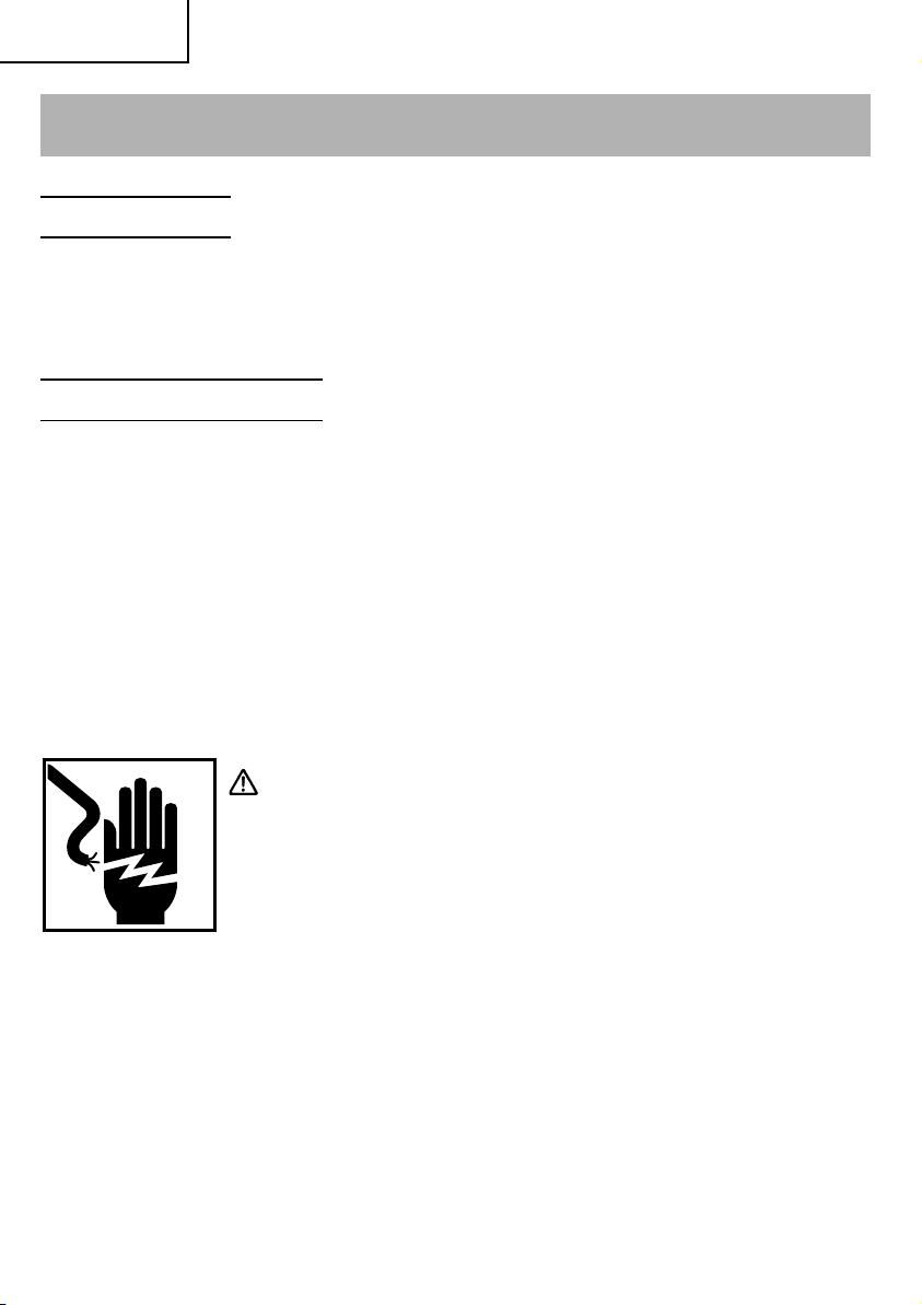
1. Hold tools by insulated gripping surfaces when performing an operation where the
cutting tool may contact hidden wiring or its own cord. Contact with a “live” wire will
make exposed metal parts of the tool “live” and shock the operator.
2. ALWAYS wear ear protectors when using the tool for extended periods.
Prolonged exposure to high intensity noise can cause hearing loss.
3. NEVER touch the tool bit with bare hands after operation.
4. NEVER wear gloves made from materials likely to roll up such as cotton, wool, cloth or
string, etc.
5. ALWAYS attach the side handle and securely grip the Rotary Hammer.
6. NEVER touch moving parts.
NEVER place your hands, fingers or other body parts near the tool’s moving parts.
7. NEVER operate without all guards in place.
NEVER operate this tool without all guards or safety features in place and in proper
working order. If maintenance or servicing requires the removal of a guard or safety
feature, be sure to replace the guard or safety feature before resuming operation of the
tool.
8. Use right tool.
Don’t force small tool or attachment to do the job of a heavy-duty tool.
Don’t use tool for purpose not intended —for example— don’t use circular saw for
cutting tree limbs or logs.
9. NEVER use a power tool for applications other than those specified.
NEVER use a power tool for applications other than those specified in the Instruction
Manual.
10. Handle tool correctly.
Operate the tool according to the instructions provided herein. Do not drop or throw
the tool. NEVER allow the tool to be operated by children, individuals unfamiliar with
its operation or unauthorized personnel.
11. Keep all screws, bolts and covers tightly in place.
Keep all screws, bolts, and plates tightly mounted. Check their condition periodically.
12. Do not use power tools if the plastic housing or handle is cracked.
Cracks in the tool’s housing or handle can lead to electric shock. Such tools should not
be used until repaired.
13. Blades and accessories must be securely mounted to the tool.
Prevent potential injuries to yourself or others. Blades, cutting implements and
accessories which have been mounted to the tool should be secure and tight.
14. Keep motor air vent clean.
The tool’s motor air vent must be kept clean so that air can freely flow at all times.
Check for dust build-up frequently.
6
English
15. Operate power tools at the rated voltage.
Operate the power tool at voltages specified on its nameplate.
If using the power tool at a higher voltage than the rated voltage, it will result in
abnormally fast motor revolution and may damage the unit and the motor may burn
out.
16. NEVER use a tool which is defective or operating abnormally.
If the tool appears to be operating unusually, making strange noises, or otherwise
appears defective, stop using it immediately and arrange for repairs by a Hitachi
authorized service center.
17. NEVER leave tool running unattended. Turn power off.
Don’t leave tool until it comes to a complete stop.
18. Carefully handle power tools.
Should a power tool be dropped or struck against hard materials inadvertently, it may
be deformed, cracked, or damaged.
19. Do not wipe plastic parts with solvent.
Solvents such as gasoline, thinner benzine, carbon tetrachloride, and alcohol may
damage and crack plastic parts. Do not wipe them with such solvents.
Wipe plastic parts with a soft cloth lightly dampened with soapy water and dry
thoroughly.
20. ALWAYS wear eye protection that meets the requirement of the latest revision of ANSI
Standard Z87.1.
21. ALWAYS be careful with buried object such as an underground wiring.
Touching live wiring or electric cable with this tool may result in electric shock.
Confirm before use whether hidden objects are present, such as electric cables within
the wall, floor or ceiling.
22. Definitions for symbols used on this tool
V ............volts
Hz .......... hertz
A ............ amperes
no .......... no load speed
W ........... watt
.......... Class II Construction
---/min ... revolutions per minute
.......... Alternating current
7

English
DOUBLE INSULATION FOR SAFER OPERATION
To ensure safer operation of this power tool, HITACHI has adopted a double insulation
design. “Double insulation” means that two physically separated insulation systems have
been used to insulate the electrically conductive materials connected to the power supply
from the outer frame handled by the operator. Therefore, either the symbol “
words “Double insulation” appear on the power tool or on the nameplate.
Although this system has no external grounding, you must still follow the normal electrical
safety precautions given in this Instruction Manual, including not using the power tool in
wet environments.
To keep the double insulation system effective, follow these precautions:
䡬 Only HITACHI AUTHORIZED SERVICE CENTER should disassemble or assemble this
power tool, and only genuine HITACHI replacement parts should be installed.
䡬 Clean the exterior of the power tool only with a soft cloth moistened with soapy water,
and dry thoroughly.
Never use solvents, gasoline or thinners on plastic components; otherwise the plastic
may dissolve.
” or the
SAVE THESE INSTRUCTIONS
AND
MAKE THEM AVAILABLE TO
OTHER USERS
AND
OWNERS OF THIS TOOL!
8
English
FUNCTIONAL DESCRIPTION
NOTE: The information contained in this Instruction Manual is designed to assist you in
the safe operation and maintenance of the power tool.
NEVER operate, or attempt any maintenance on the tool unless you have first read
and understood all safety instructions contained in this manual.
Some illustrations in this Instruction Manual may show details or attachments that
differ from those on your own power tool.
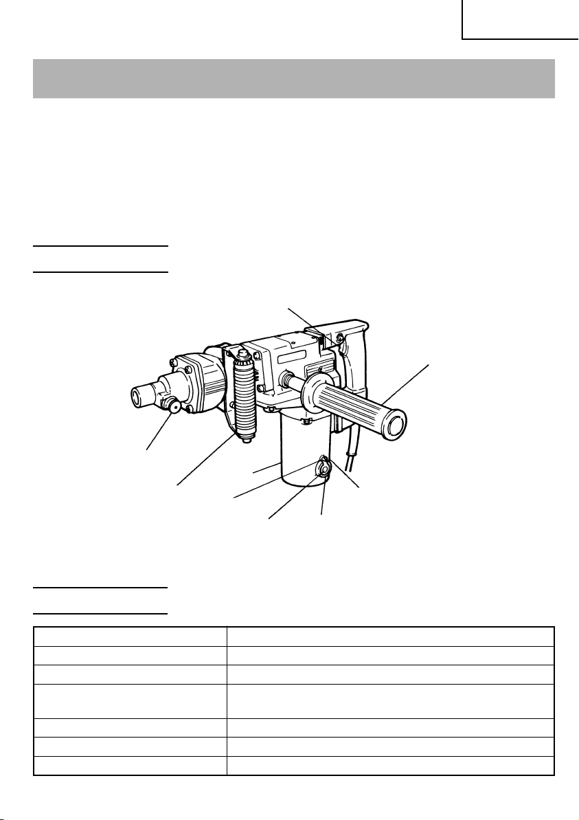
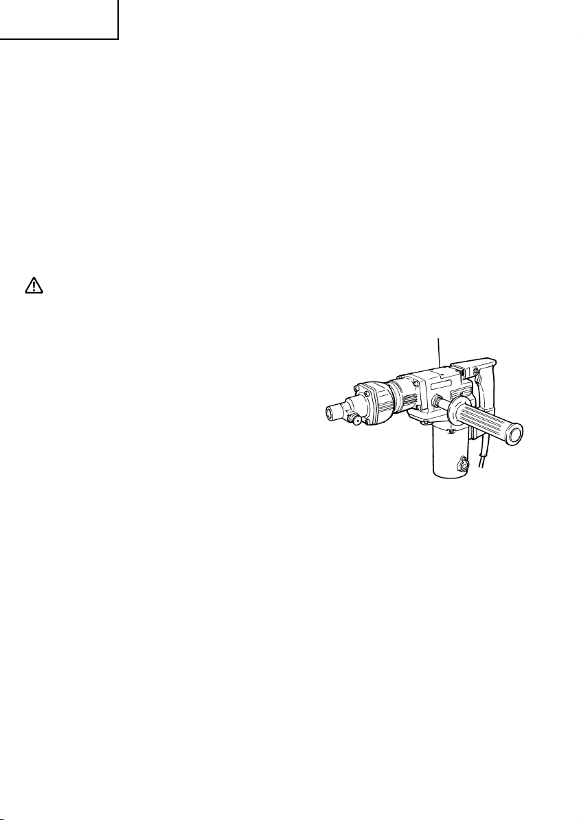
NAME OF PARTS
Switch trigger
Bar type handle
Tool holder
Housing
D type handle
Set screw
Cap cover
Brush cap
(under the cap cover)
Fig. 1
Nameplate
SPECIFICATIONS
Motor Single-Phase, Series Commutator Motor.
Power Source Single-Phase, 120 V 60 Hz
Current 10 A
Capacity Drill Bit: 2" (50 mm)
Core Bit: 5" (125 mm)
No-Load Speed 300/min
Full-load Blow 2,450/min
Weight 19.2 lbs (8.7 kg)
9
English
ASSEMBLY AND OPERATION
APPLICATIONS
䡬 Drilling anchor holes
䡬 Drilling holes in concrete
䡬 Crushing concrete, chipping, digging, and squaring
(by applying optional accessories)
PRIOR TO OPERATION
1. Power source
Ensure that the power source to be utilized conforms to the power source requirements
specified on the product nameplate.
2. Power switch
Ensure that the switch is in the OFF position. If the plug is connected to a receptacle
while the switch is in the ON position, the power tool will start operating immediately
and can cause serious injury.
3. Extension cord
When the work area is far away from the power source, use an extension cord of
sufficient thickness and rated capacity. The extension cord should be kept as short as
practicable.
WARNING:
Damaged cord must be replaced or repaired.
4. Check the receptacle
If the receptacle only loosely accepts the plug, the receptacle must be repaired. Contact
a licensed electrician to make appropriate repairs.
If such a faulty receptacle is used, it may cause overheating, resulting in a serious
hazard.
5. Confirming condition of the environment:
Confirm that the work site is placed under appropriate conditions conforming to
prescribed precautions.
10
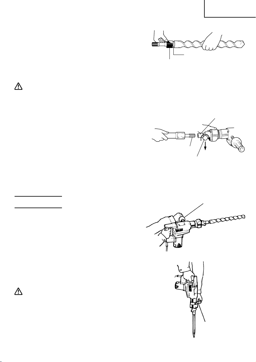
6. How to install dust cover (Fig. 2)
Always install the dust cover on the drill bit or
the taper shank adaptor. Insert the dust cover
until it lies flush in the groove.
NOTE: For a thick drill bit, insert the dust cover
from drill rear.
7. How to install tool
CAUTION:
For tools such as a bull point and a cold chisel,
use only Hitachi genuine parts.
(1) Clean, then smear the tool shank with the
grease provided.
(2) Slide the tool holder in the direction of arrow
A and rotate it 180˚.
Turn the notch of the tool shank downward and
insert it fully into the hexagonal hole of the
front cover. (Fig. 3)
(3) Turn the tool holder and align the front cover
mark with the tool holder mark to secure.
NOTE: Remove in the reverse order to
installation.
Dust cover
Tool shank
English
Insert up to the
groove
Fig. 2
Front cover
A
Tool holder
Fig. 3
HOW TO USE
1. How to drill holes (Fig. 4)
(1) Use the Bar type handle.
Do not use D type handle when drilling
operation, since it may not be enough to hold
the body firmly.
(2) Pull the switch trigger after applying the drill
bit tip to the drilling position.
(3) It is unnecessary to forcibly press the Rotary
Hammer main body. It is sufficient to slightly
press the rotary hammer to an extent that clips
are freely discharged.
CAUTION:
Although this machine is equipped with a
safety clutch, if the drill bit becomes bound in
concrete or other material, the resultant
stoppage of the drill bit could cause the
machine body to turn in reaction. Ensure that
the main handle and bar type handle are
gripped firmly during operation.
Bar type handle
Fig. 4
D type handle
Fig. 5
11
English
2. How to chip or crushing
(1) Use the D type handle.
(2) By applying the bull point tip to the chipping
or crushing position, operate the rotary
hammer by utilizing its own weight.
Forcible pressing or thrusting is unnecessary.
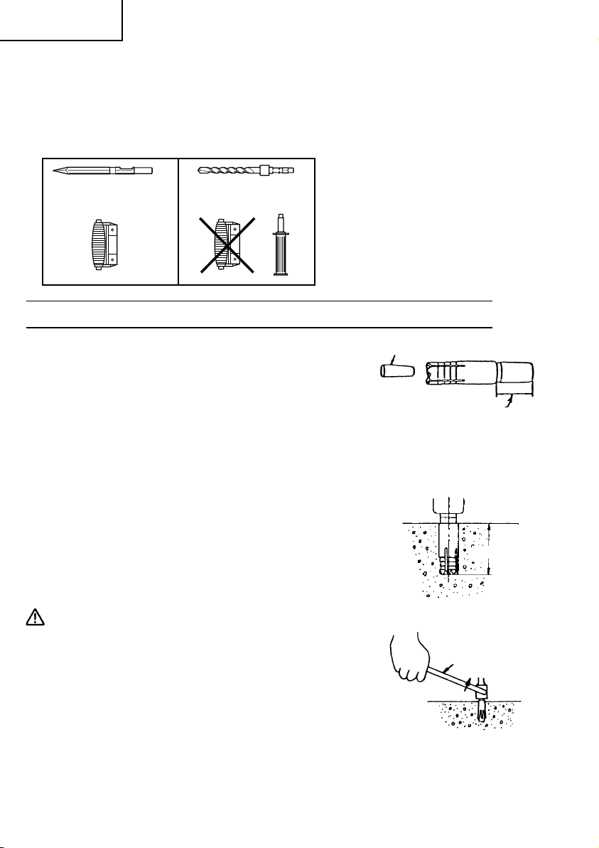
DRILLING AND DRIVING-IN OPERATIONS FOR ANCHORS
Use the optional accessories for anchors, such
as anchor adapter and taper shank adapter.
1. When a rotation-striking anchor adapter
is used.
(1) Install the self-drilling anchor in the anchor
adapter (Fig. 6).
(2) Turn on the switch and drill a base hole with
the self-drilling anchor. (Fig. 7)
At the start of the hole-drilling slightly tilt the
hammer drill to determine the hole position.
(3) After cleaning out dust with a syringe, attach
the plug to the anchor tip and drive in the
anchor with a hand hammer.
(4) After driving in the anchor, use the drift key to
separate the anchor. (Fig. 8)
(5) By employing a hand hammer or pliers, snap
off the tapered portion of the anchor. (Fig. 9)
CAUTION:
Since the snapped-off tapered portion will fly
about, pay attention to the snapping direction.
Plug
Snap off this portion
after driving in the selfdrilling anchor.
Fig. 6
Hole depth
Fig. 7
Drift key
Gouge
Fig. 8
12
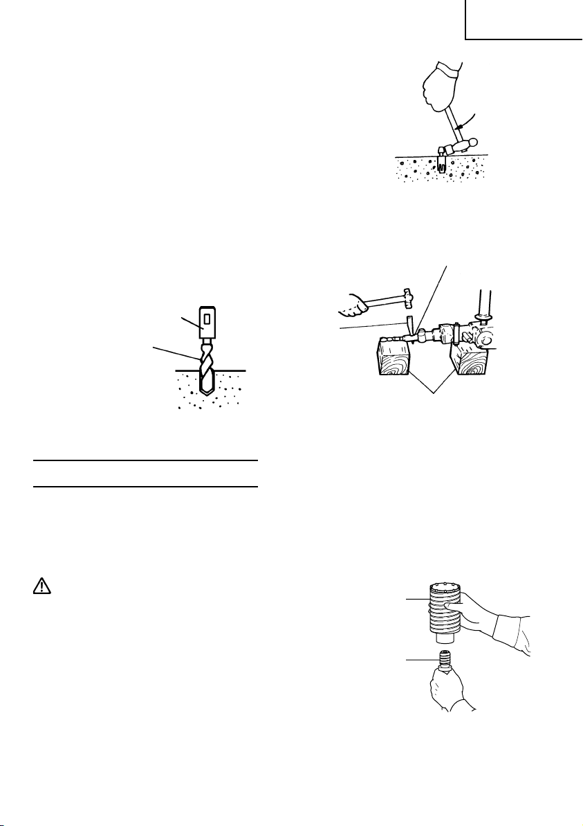
2. How to use the drill bit (taper shank) and
the taper shank adaptor.
(1) Install drill bit with taper shank in the taper
shank adaptor. (Fig. 10)
(2) Turn the power on and drill a base hole.
(3) After cleaning out dust with a syringe, attach
the plug to the anchor tip and drive in the
anchor with a manual hammer.
(4) To remove the drill bit with taper shank, insert
a cotter into the slot of the taper shank adaptor,
place supports under the Rotary Hammer and
tap the cotter with a manual hammer. (Fig. 11)
Taper shank adaptor
Drill bit
(Taper shank)
Fig. 10
Cotter
English
Fig. 9
Taper shank
adaptor
Support
Fig. 11
HOW TO USE THE CORE BIT
When a core bit is used, large caliber holes and blind holes can be drilled. In this case, use
optional accessories for core bits (such as a center pin and core bit shank) for more rational
operation.
1. Mounting
CAUTION:
Prior to mounting a core bit, always disconnect
the plug from the power supply receptacle.
(1) Mount the core bit on the core bit shank.
(Fig. 12) Before that, feed oil the screw portion
of core bit shank for easily dismount.
Core bit
Core bit
shank
Fig. 12
13
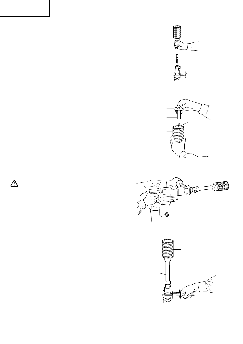
English
(2) Mount the core bit shank on the main body in
the same manner as in mounting the drill bit
and the bull point. (Fig. 13)
(3) Insert the center pin into the guide plate until
it reaches the extremity.
(4) Fit in the guide plate by aligning its concaved
portion with the core bit tip. When the position
of the concave is shifted by turning the guide
plate right or left, the guide plate never slips
off even when the rotary hammer is used in a
downward direction. (Fig. 14)
Fig. 13
2. Drilling holes
(1) Insert the plug into a power supply receptacle.
(2) A spring is built in the center pin. By straightly
and gently pressing it to the wall or floor
surface, the entire surface of the core bit tip
attains contact to start the hole drilling job. (Fig.
15)
(3) When the hole depth reaches approximately
3/16" (5 mm), the hole position can be
determined. Then remove the center pin and
guide plate from the core bit and continue the
hole drilling job.
CAUTION:
When removing the center pin and guide plate,
always disconnect the plug from the power
supply receptacle.
3. How to dismount the core bit (Fig. 16)
(1) By holding the rotary hammer (with the core
bit inserted) in an upward position, drive the
rotary hammer to repeat impact operation two
or three times, whereby the screw is loosened
and the rotary hammer becomes ready for
disassembly.
(2) Remove the core bit shank from the rotary
hammer, hold the core bit with one hand, and
strongly strike the head of the hexagonal
portion of the core bit shank with a hand
hammer two or three times, whereby the round
head screw is loosened and the rotary hammer
is ready for disassembly.
Guide
plate
Center pin
Core bit
Core bit
shank
Core
bit tip
Fig. 14
Fig. 15
Core bit
Fig. 16
14
English
MAINTENANCE AND INSPECTION
WARNING: Be sure to switch power OFF and disconnect the plug from the
receptacle during maintenance and inspection.
1. Inspecting the drill bits
Since use of a dull tool will cause motor malfunctioning and degraded efficiency, replace
the drill bit with a new one or resharpening without delay when abrasion is noted.
2. Inspecting the screws
Regularly inspect all screws and ensure that they are properly tightened. Should any of
the screws be loose, retighten them immediately.
WARNING: Using this Rotary Hammer with loosen screws is extremely dangerous.
3. Maintenance of the motor
The motor unit winding is the very “heart” of the power tool. Exercise due care to
ensure the winding does not become damaged and/or wet with oil or water.
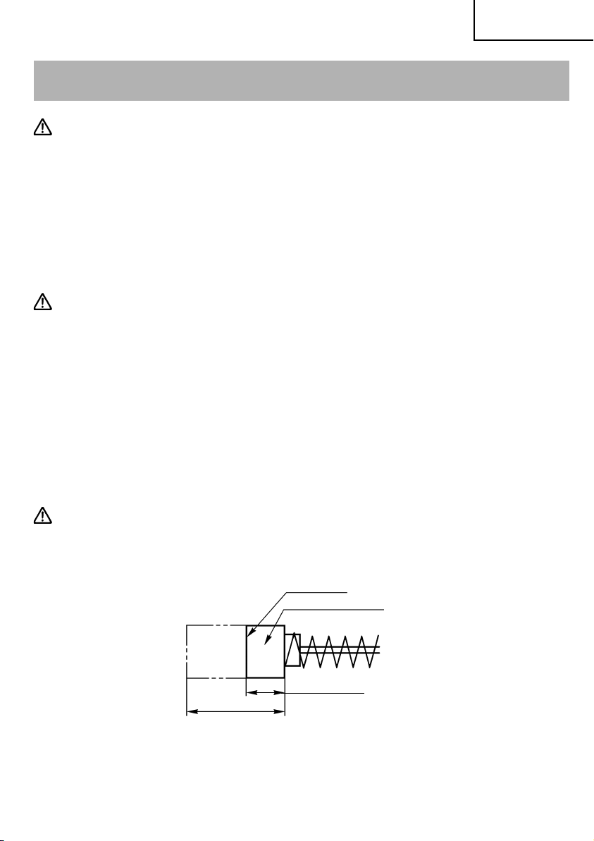
4. Inspecting the carbon brushes: (Fig. 17)
The motor employs carbon brushes which are consumable parts. When they become
worn to or near “wear limit”, it could result in motor trouble. When an auto-stop carbon
brush is equipped, the motor will stop automatically. At that time, replace both carbon
brushes with new ones which have the same carbon brush Nos. shown in the figure.
In addition, always keep carbon brushes clean and ensure that they slide freely within
the brush holders.
CAUTION:
Using this Rotary Hammer with a carbon brush which is worn in excess of the wear
limit will damage the motor.
Wear limit
No. of carbon brush
71
0.28" (7 mm)
0.67" (17 mm)
Fig. 17
NOTE: Use HITACHI carbon brush No. 71 indicated in Fig. 17
15
English
䡬 Replacing carbon brushes:
(For parts name, refer to Fig. 1)
Loosen the set screw then remove the cap cover. Remove the brush cap and carbon
brush. After replacing the carbon brush, do not forget to tighten the brush cap securely
and to install the cap cover.
5. How to replace grease
This machine is full air-tight construction to protect against dust and to prevent lubricant
leakage. Therefore, the machine can be used without lubrication for long periods.
Replace the grease as described below.
䡬 Grease replacement period
After purchase, replace grease after every 6 months of usage. Ask for grease replacement
at the nearest HITACHI Authorized Service Center. Proceed for replacement of grease.
䡬 Grease replenishment
CAUTION:
Before replenishing the grease, turn the power off and pull out the power plug.
(1) Remove the crank cover and wipe off the
grease inside. (Fig. 18)
(2) Apply 0.7 oz (20 g) of HITACHI Electric Hammer
Grease A (standard accessory, contained in
tube) to the crank case.
As the tube contains 1 oz (30 g) of grease,
supply 2/3 of the contained grease.
(3) After replenishing the grease, install the crank
cover securely.
Crank cover
NOTE: The HITACHI Electric Hammer Grease
A is of the lower viscosity type. When
the supplied grease tube is consumed,
purchase from a HITACHI Authorized
Service Center.
Fig. 18
6. Service and repairs
All quality power tools will eventually require servicing or replacement of parts because
of wear from normal use. To assure that only authorized replacement parts will be
used, all service and repairs must be performed by a HITACHI AUTHORIZED SERVICE
CENTER, ONLY.
7. Service parts list
A: Item No.
B: Code No.
C: No. Used
D: Remarks
16

English
CAUTION: Repair, modification and inspection of Hitachi Power Tools must be carried
out by a Hitachi Authorized Service Center.
This Parts List will be helpful if presented with the tool to the Hitachi
Authorized Service Center when requesting repair or other maintenance.
In the operation and maintenance of power tools, the safety regulations
and standards prescribed in each country must be observed.
MODIFICATIONS:
Hitachi Power Tools are constantly being improved and modified to incorporate the
latest technological advancements.
Accordingly, some parts (i.e. code numbers and/or design) may be changed without
prior notice.
17
English
ACCESSORIES
WARNING: ALWAYS use Only authorized HITACHI replacement parts and
accessories. NEVER use replacement parts or accessories which are
not intended for use with this tool. Contact HITACHI if you are not sure
whether it is safe to use a particular replacement part or accessory
with your tool.
The use of any other attachment or accessory can be dangerous and
could cause injury or mechanical damage.
NOTE: Accessories are subject to change without any obligation on the part of the HITACHI.
STANDARD ACCESSORIES
(1) Case (Molded plastic) (Code No. 319784) .......................................................................... 1
(2) D type Handle (Code No. 986959) ...................................................................................... 1
(3) Bar Type Handle (Code No. 956259) .................................................................................. 1
(4) Dust Cover (Code No. 993245) ........................................................................................... 1
(5) Allen Wrench 6 mm (Code No. 872422) ............................................................................ 1
(6) Hammer Grease A (Code No. 981840) ............................................................................... 1
OPTIONAL ACCESSORIES.....sold separately
For accessories in detail please call HITACHI AT 1-800-59-TOOLS
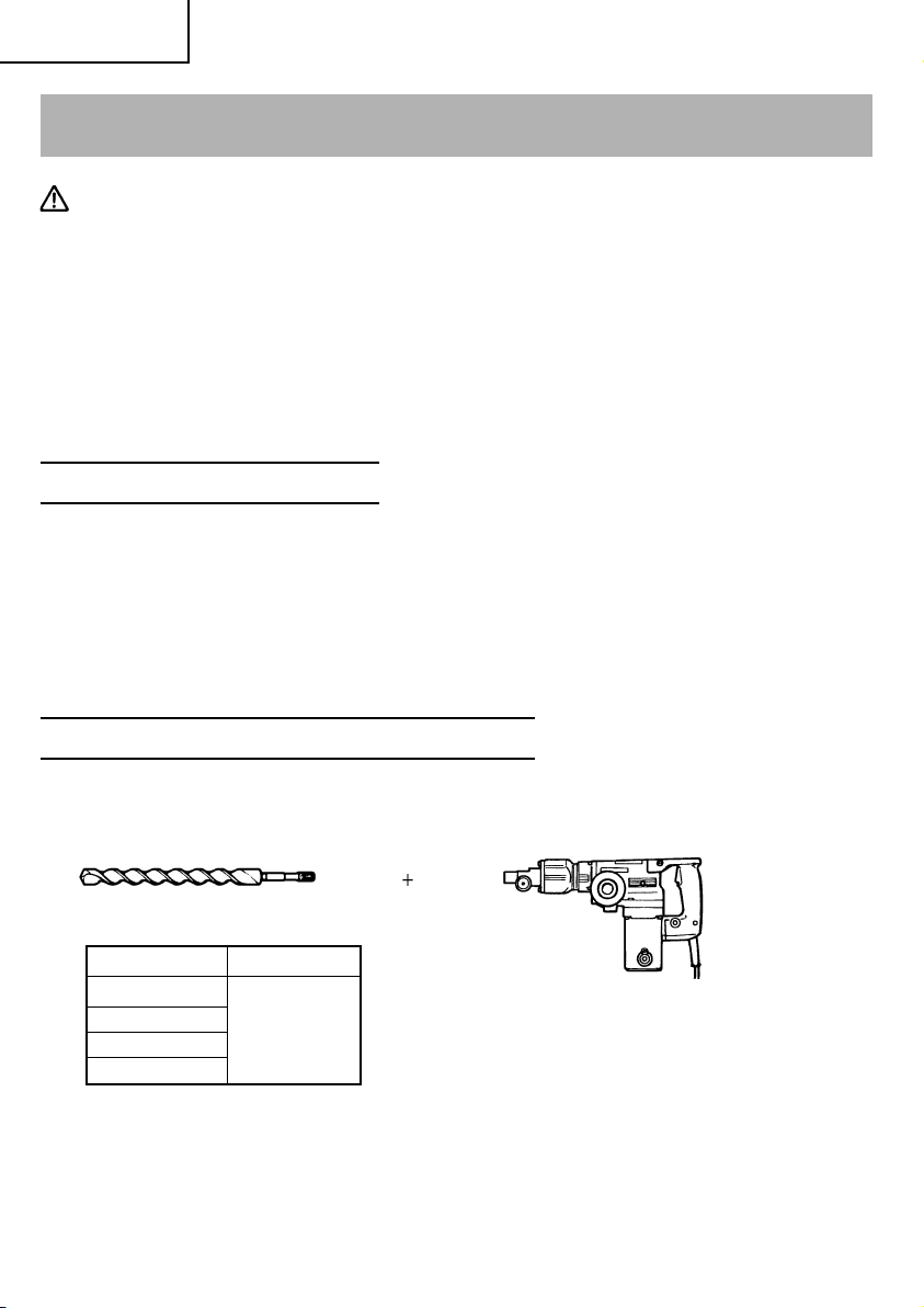
1. Through-hole drilling (Rotation + Hammering)
(1) Drill bit (Spline shank)
External dia. Overall length
1/2" (13.1 mm)
1" (26.2 mm)
1-1/2" (39 mm)
2" (50 mm)
18
16" (406 mm)
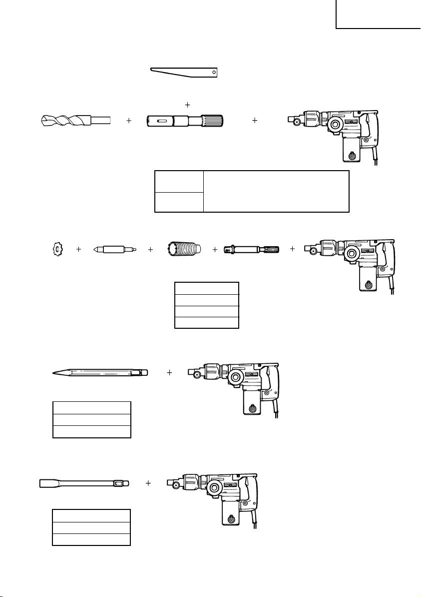
2. Anchor hole drilling (Rotation + Hammering)
(3) Cotter
English
(1) Drill bit
(Taper shank)
(2) Taper shank adaptor
(Spline shank)
A-taper
B-taper
Taper shank adaptor formed
A-taper or B-taper is provided as
optional accessory, but drill bit for
it is not provided
3. Large-dia. hole boring (Rotation + Hammering)
(Guide plate)
(1) Center pin (3) Core bit shank
(2) Core bit
External dia.
2" (50 mm)
4-1/8" (105 mm)
5" (125 mm)
4. Crushing (Hammering)
(1) Bull point
Overall length
12" (300 mm)
18" (460 mm)
(Spline shank)
5. Groove digging and edging (Hammering)
(1) Cold chisel
Overall length
12" (300 mm)
18" (460 mm)
19
English
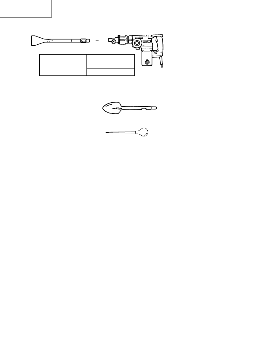
6. Asphalt cutting (Hammering)
(1) Cutter
Overall length Width
12" (300 mm)
7. Digging
(1) Scoop
8. Syringe (for chip removal)
NOTE: Specifications are subject to change without any obligation on the part of the
HITACHI.
1-1/2" (38 mm)
2" (50 mm)
20