

Hitachi 50HDT55 Owner's Manual
PLASMA TELEVISION
AVC (Audio Video Control Center) & Plasma Display Monitor
32HDT55
42HDT55
50HDT55
OPERATING GUIDE
IMPORTANT SAFETY INSTRUCTIONS 2-3
FIRST TIME USE 4-23
THE REMOTE CONTROL
ON-SCREEN DISPLAY
USEFUL INFORMATION INDEX 76-84
Setup
Locks
Ch. Manager
Audio
Video
Move
SEL
Sel
POWER
TV
VCR
CBL
DVD
1
2
4
56
3
7
89
0
INFOSLEEP
A/V NET
EXIT
MENU
CHVOL
MUTE
PIP
PIP CH
SWAP
FREEZE
PIP MODE
PIP ACCESS
VIDEO
SOURCE WIZARD
REC
SELECT
TV/RGB
ASPECT
STB
ANT
L
A
S
T
C
H
V
C
R
P
L
U
S
+
S
V
C
S
G
U
I
D
E
/
T
V
S
C
H
D
V
I
D
1
V
I
D
2
V
I
D
3
V
I
D
4
V
I
D
5
TAPE
CD
AMP
MODE
CLU-5723TSI
42-65
24-41
Locks
Chan. Manager
Aspect
Audio
Video
Move
SEL
Sel
Setup
USING THE RGB INPUT
OF THE PLASMA TV
66-75
2
IMPORTANT
SAFETY POINTS YOU SHOULD KNOW ABOUT
YOUR HITACHI PLASMA TELEVISION
Our reputation has been built on the quality, performance, and ease of service of HITACHI Plasma Televisions.
Safety is also foremost in our minds in the design of these units. To help you operate these products properly, this
section illustrates safety tips which will be of benefit to you. Please read it carefully and apply the knowledge you
obtain from it to the proper operation of your HITACHI Plasma Television.
Please fill out your warranty card and mail it to HITACHI. This will enable HITACHI to notify you promptly in the
improbable event that a safety problem should be discovered in your product model.
Follow all warnings and instructions marked on this plasma television.Plasma television consists of A VC center and display monitor .
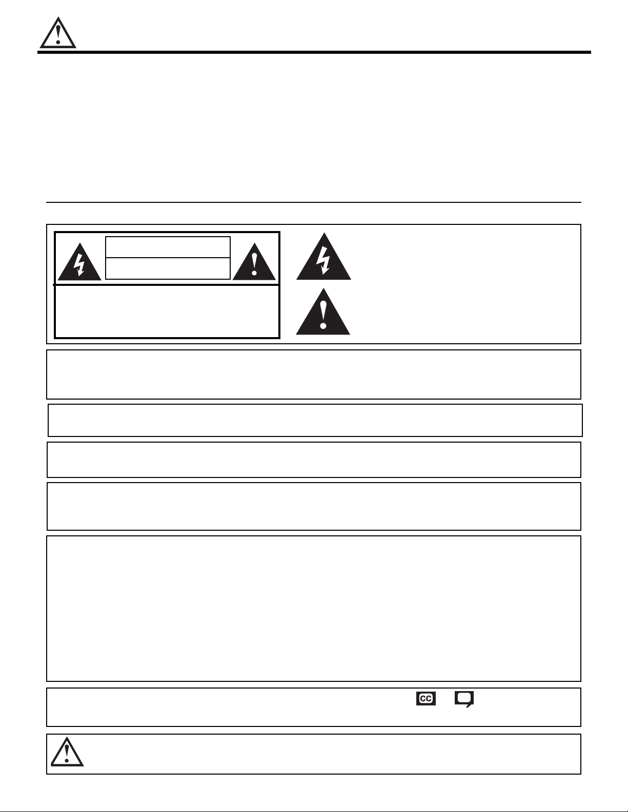
CAUTION
RISK OF ELECTRIC SHOCK
DO NOT OPEN
CAUTION: TO REDUCE THE RISK OF ELECTRIC SHOCK,
DO NOT REMOVE COVER (OR BACK).
NO USER SERVICEABLE PARTS INSIDE.
REFER SERVICING TO QUALIFIED SERVICE PERSONNEL.
The lightning flash with arrowhead symbol, within an equilateral
triangle, is intended to alert the user to the presence of uninsulated
“dangerous voltage” within the product’s enclosure that may be of a
sufficient magnitude to constitute a risk of electric shock to persons.
The exclamation point within an equilateral triangle, is intended to
alert the user to the presence of important operating and
maintenance (servicing) instructions in the literature accompanying
the appliance.
WARNING:
TO PREVENT FIRE OR SHOCK HAZARD, DO NOT EXPOSE THIS PLASMA TELEVISION
TO RAIN OR MOISTURE.
NOTE: • There are no user serviceable parts inside the AVC center/display monitor.
• Model and serial numbers are indicated on back side of the AVC center/display monitor.
POWER SOURCE
THIS PLASMA
TELEVISION
IS DESIGNED TO OPERATE ON 120 VOLTS 60Hz, AC CURRENT. INSERT
THE AVC CENTER AND DISPLAY MONITOR POWER CORD INTO A 120 VOLT 60Hz OUTLET.
TO PREVENT ELECTRIC SHOCK, DO NOT USE THE PLASMA TELEVISION’S (POLARIZED) PLUG WITH
AN EXTENSION CORD, RECEPTACLE, OR OTHER OUTLET UNLESS THE BLADES AND GROUND
TERMINAL CAN BE FULLY INSERTED TO PREVENT BLADE EXPOSURE.
NEVER CONNECT THE
AVC CENTER/DISPLAY MONITOR
TO 50Hz, DIRECT CURRENT, OR ANYTHING
OTHER THAN THE SPECIFIED VOLTAGE.
CAUTION: Never remove the back cover of the AVC center/display monitor as this can expose you to very high
voltages and other hazards. If the television does not operate properly, unplug the Plasma Television and
call your authorized dealer or service center.
NOTE: This Plasma Television will display television closed captioning, ( or ), in accordance with
paragraph 15.119 of the FCC rules.
CAUTION:
Adjust only those controls that are covered in the instructions, as improper changes or modifications not
expressly approved by HITACHI could void the user’s authority to operate the Plasma Television.
MODIFICATIONS:
The FCC requires the user to be notified that any changes or modifications made to this device that
are not expressly approved by Hitachi America, Ltd. Home Electronics Division may void the user’s
authority to operate the equipment.
SAFETY TIPS
3
Read before operating equipment
Follow all warnings and instructions marked on this television.
1. Read these instructions.
2. Keep these instructions.
3. Heed all warnings.
4. Follow all instructions.
5. Do not use this apparatus near water.
6. Clean only with a dry cloth.
7. Do not block any ventilation openings. Install in
accordance with the manufacturer’s instructions.
8. Do not install near any heat sources such as radiators,
heat registers, stoves, or other apparatus (including
amplifiers) that produce heat.
9. Do not defeat the safety purpose of the polarized or
grounding-type plug. A polarized plug has two blades
with one wider than the other. A grounding type plug
has two blades and a third grounding prong. The wide
blade or the third prong are provided for your safety. If
the provided plug does not fit into your outlet, consult
an electrician for replacement of the obsolete outlet.
10.Protect the power cord from being walked on or
pinched particularly at plugs, convenience receptacles,
and the point where they exit from the apparatus.
11. Only use the attachments/accessories specified by the
manufacturer.
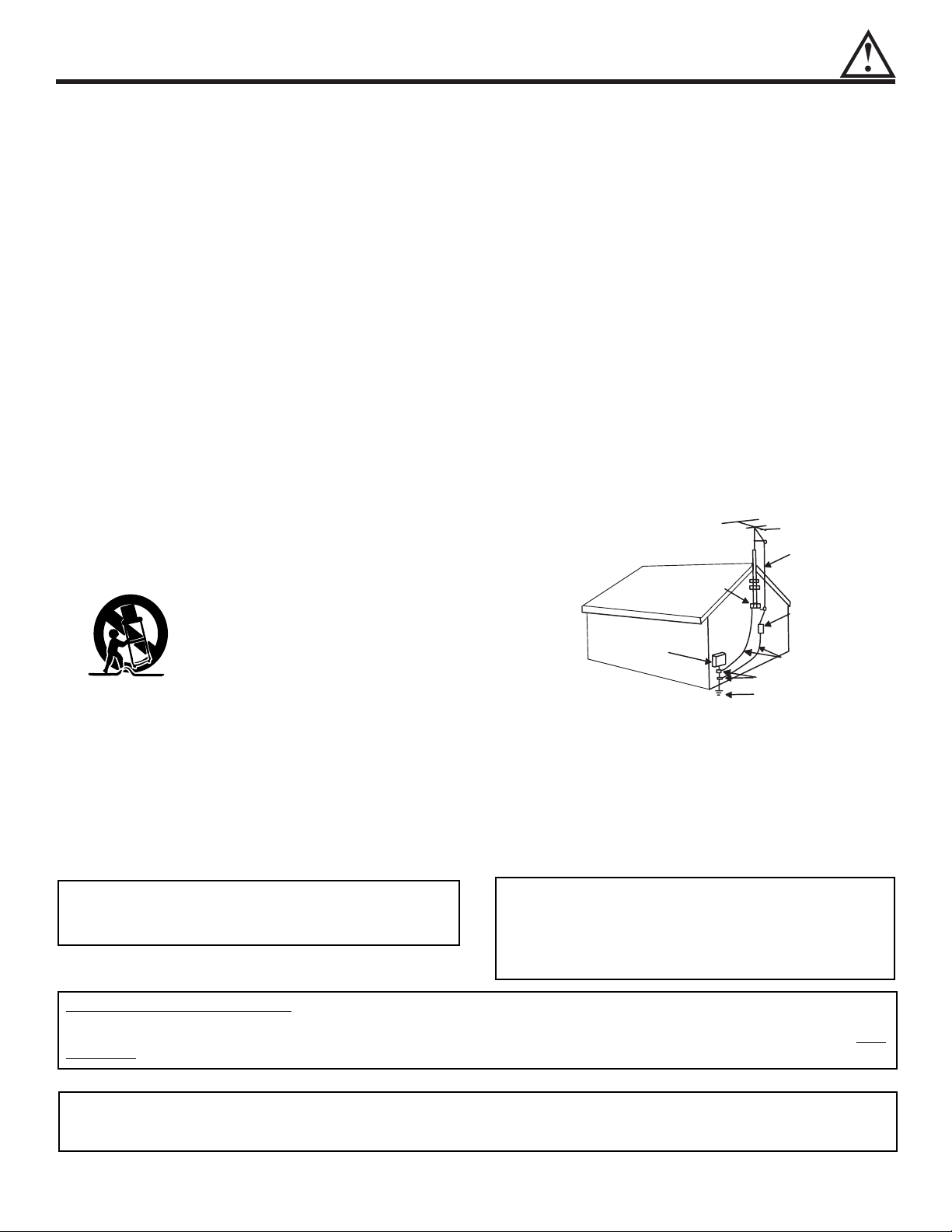
12. Use only with the cart, stand, tripod, bracket,
or table specified by the manufacturer, or
sold with the apparatus. When a cart is
used, use caution when moving the
cart/apparatus combination to avoid injury
from tip-over.
13.Unplug this apparatus during lightning storms or when
unused for long periods of time.
14.Refer all servicing to qualified service personnel.
Servicing is required when the apparatus has been
damaged in any way, such as power-supply cord or
plug is damaged, liquid has been spilled or objects
have fallen into apparatus, the apparatus has been
exposed to rain or moisture, does not operate
normally, or has been dropped.
15.Televisions are designed to comply with the
recommended safety standards for tilt and stability.
Do not apply excessive pulling force to the front, or top,
of the cabinet which could cause the product to
overturn resulting in product damage and/or personal
injury.
16.Follow instructions for wall, shelf or ceiling mounting as
recommended by the manufacturer.
17.An outdoor antenna should not be located in the
vicinity of overhead power lines or other electrical
circuits.
18.If an outside antenna is connected to the receiver be
sure the antenna system is grounded so as to provide
some protection against voltage surges and built up
static charges. Section 810 of the National Electric
Code, ANSI/NFPA No. 70-1984, provides information
with respect to proper grounding for the mast and
supporting structure, grounding of the lead-in wire to
an antenna discharge unit, size of grounding
connectors, location of antenna-discharge unit,
connection to grounding electrodes and requirements
for the grounding electrode.
Note to the CATV system installer: This reminder is
provided to call the CA TV system installer’s attention to
Article 820-40 of the NEC that provides guidelines for
proper grounding and, in particular, specifies that the
cable ground shall be connected to the grounding
system of the building, as close to the point of cable
entry as practical.
ANTENNA
LEAD IN
WIRE
ANTENNA
DISCHARGE UNIT
(NEC SECTION 810-20)
GROUNDING CONDUCTORS
(NEC SECTION 810-21)
GROUNDING CONDUCTORS
POWER SERVICE GROUNDING
ELECTRODE SYSTEM
(NEC ART 250 PART H)
NEC NATIONAL ELECTRICAL CODE
ELECTRIC
SERVICE
EQUIPMENT
GROUND
CLAMP
Do not place any objects on the top of the
television which may fall or cause a child to climb
to retrieve the objects.
Disposal of this product may require specific
instructions pertaining to your resident state. For
disposal or recycling information, please contact
your local authorities or the Electronic Industries
Alliance: www.eiae.org.
PREVENTION OF SCREEN BURN
Continuous on-screen displays such as video games, stock market quotations, computer generated graphics, and other fixed (nonmoving) patterns can cause permanent damage to television receivers. Such “SCREEN BURNS” constitute misuse and are NOT
COVERED by your HITACHI Factory Warranty.
PUBLIC VIEWING OF COPYRIGHTED MATERIAL
Public viewing of programs broadcast by TV stations and cable companies, as well as programs from other sources, may require
prior authorization from the broadcaster or owner of the video program material.
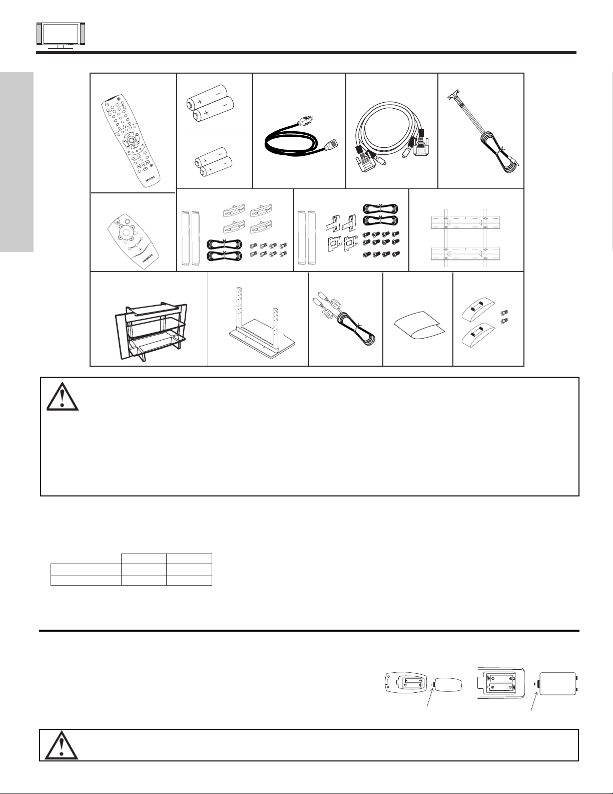
ACCESSORIES
4
FIRST TIME USE
1. Remote Control Unit CLU-5726TSI (P# HL01826). 8. Speaker Accessories (42” only) (P#GM01195).
2. Simple Remote Control Unit CLU-120S (P#HL01861). 9. Speaker Accessories (50” only) (P#GM01233).
3. Two “AA” size, 1.5V batteries (P# FQ00021). 10. Wall Mount Unit WM50 (Optional) (P#QX00563).
4. Two “AAA” size, 1.5V batteries (P# FR00061). 11. 32” Stand (SPD32 P# H520441) (Optional).
5. Power Cord: 42” Stand (SPD42 P# H520442) (Optional).
12. 50” Table Top Stand (50STD3) (P#QD35632).
13. Sub Woofer Cable (P# VZ11701).
6. Monitor Connection Cable (P#EW07883). 14. Cleaning Cloth (P#MS00803).
7. Two IR Mouse cables (P# EY01641). 15. AVC Stand Accessories (P#QJ01081).
REMOTE CONTROL BATTERY INSTALLATION AND REPLACEMENT
1. Open the battery cover of the remote control by pushing the notched part of the cover with your fingers and pulling the
cover off.
2. Insert two new “AA” and “AAA” size batteries for the remote control and
simple remote control respectively. When replacing old batteries, push
them towards the springs and lift them out.
3. Match the batteries to the (+) and (-) marks in the battery compartment.
4. Replace the cover.
BOTTOM VIEW
Lift up on tab to
remove back cover.
Lift up on tab to
remove back cover.
(Remote Control)
BOTTOM VIEW
(Simple Remote Control)
CAUTION: Danger of explosion if battery is incorrectly replaced. Replace with the same or equivalent type.
CAUTION: 1. The plasma display wall mount unit WM50 is for use only with Hitachi model 32HDT55, 42HDT55 and
50HDT55.
2. Ceiling mounting is not recommended. Mounting the panel on the ceiling does not provide adequate
ventilation for the electronics or proper support for the front glass panel. This plasma television product is
designed for a maximum tilting angle of 45 degrees from vertical.
3. This SPD32 PDP stand for use only with Hitachi 32HDT55. Use with other apparatus is capable of resulting
in instability causing possible injury.
4. This SPD42 PDP stand for use only with Hitachi 42HDT55 Use with other apparatus is capable of resulting
in instability causing possible injury.
5. This 50STD3 stand for use only with Hitachi 50HDT55. Use with other apparatus is capable of resulting in
instability causing possible injury. See important marking located on bottom of stand.
REMOTE “AA” BATTERIES POWER CORD MONITOR IR MOUSE
CONTROL CONNECTION CABLE CABLE
5. 6. 7.
SPEAKER ACCESSORIES
(42”)
1.
WALL MOUNT UNIT WM50
(OPTIONAL)
PDP TV STAND (OPTIONAL)
32” (SPD32 P#H520441)
42” (SPD42 P#H520442)
10.
50STD3 Table Top Stand
12.
4.
SPEAKER ACCESSORIES
(50”)
8.
9.
Subwoofer Cable
13.
AVC Stand
Accessories
14. 15.
Cleaning Cloth
“AAA”BATTERIES
3.
11.
SIMPLE REMOTE
CONTROL
2.
POWER
TV
VCR
CBL
DVD
1
2
4
56
3
7
89
0
I
NFO
SLEEP
A/V NET
EXIT
MENU
CHVOL
MUTE
PIP SURF
SWAP
FREEZE
PIP MODE
PIP ACCESS
DAY/NIGHT
SOURCE WIZARD
REC
SELECT
TV/RGB
ASPECT
STB
ANT
LAST CH
V
I
D
1
V
I
D
2
VID 3
VID 4
V
ID
5
PVR
CD
AMP
VIDEO
Check to make sure you have the following accessories before disposing of the packing material.
32”/42” 50”
Plasma Monitor EV01841 EV01861
AVC EV01841 EV01841
M
U
T
E
F
A
V
C
H
S
E
L
E
C
T
VOL +
C
H
-
C
H
+
A
/V
N
E
T
VOL -
M
E
N
U
A
N
T
P
O
W
E
R
E
X
IT
C
B
A
C«
B
«
A«
C
B
A
C
«
B
«
A«
HOW TO SETUP YOUR NEW HITACHI PLASMA TELEVISION
5
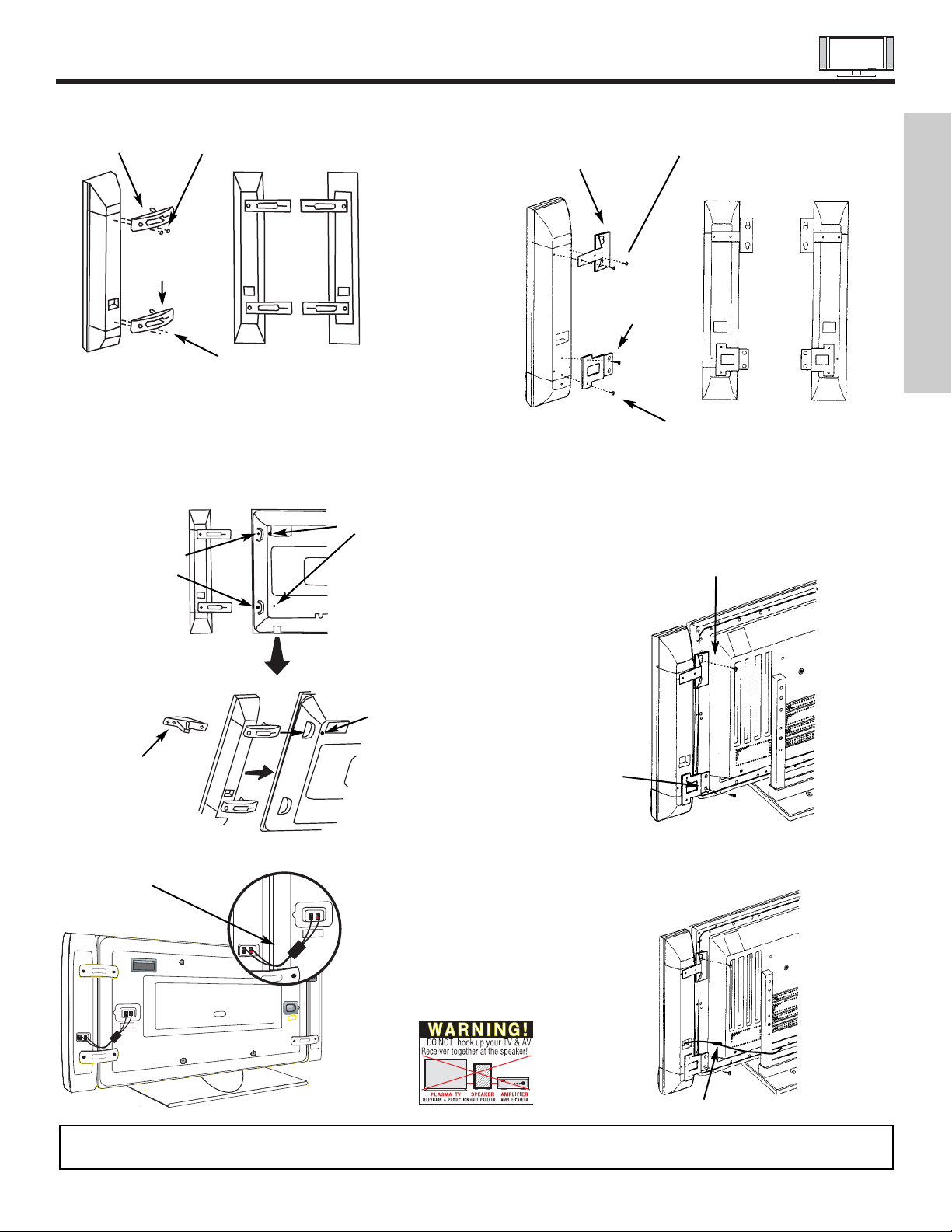
SPEAKER INSTALLATION 42”
1. Screw the speaker holder to the speakers as shown below.
2. Loosen 4 screws (A) (two on the left and two on the right).
3. Completely unscrew 4 screws (B) (two on the left and two on
the right).
4. Hook the speaker holders to the loosened screws (A).
5. Screw the speaker holders to the Display Monitor with
screws (B).
6. Tighten screws (A).
Speaker Holder
Speaker
Holder
Screw x2
Screw x2
(R)
(R) (L)
(R) Speaker
Loosen
Screw
(A)
Unscrew (B)
Completely
Bottom View
of Speaker
Holder
Hook this
portion to the
loose screws
(A).
Screw in
screws (B)
Insert
horizontally from
the side
7. Connect the speaker wires as shown below. (Make sure the
core is toward the display monitor side.)
NOTES: Do not connect speakers simultaneously to the speaker terminal of the Plasma TV and an external amplifier.
Core
FIRST TIME USE
Speaker Holder
Speaker Holder
Screw x2
Screw x2
(R)
(R) (L)
Screw in
screws (C)
Screw in
screws (D)
SPEAKER INSTALLATION 50”
1. Screw the speaker holder to the speakers as shown below.
2. Screw in screw (C).
3. Hook the upper speaker holder to the screw in (C).
4. Screw in the lower speaker holder (D).
5. Tighten screws (C) and (D).
6. Connect the speaker wires as shown below. (Make sure the
core is toward the display monitor side.)
Ferrite Core
HOW TO SETUP YOUR NEW HITACHI PLASMA TELEVISION
6
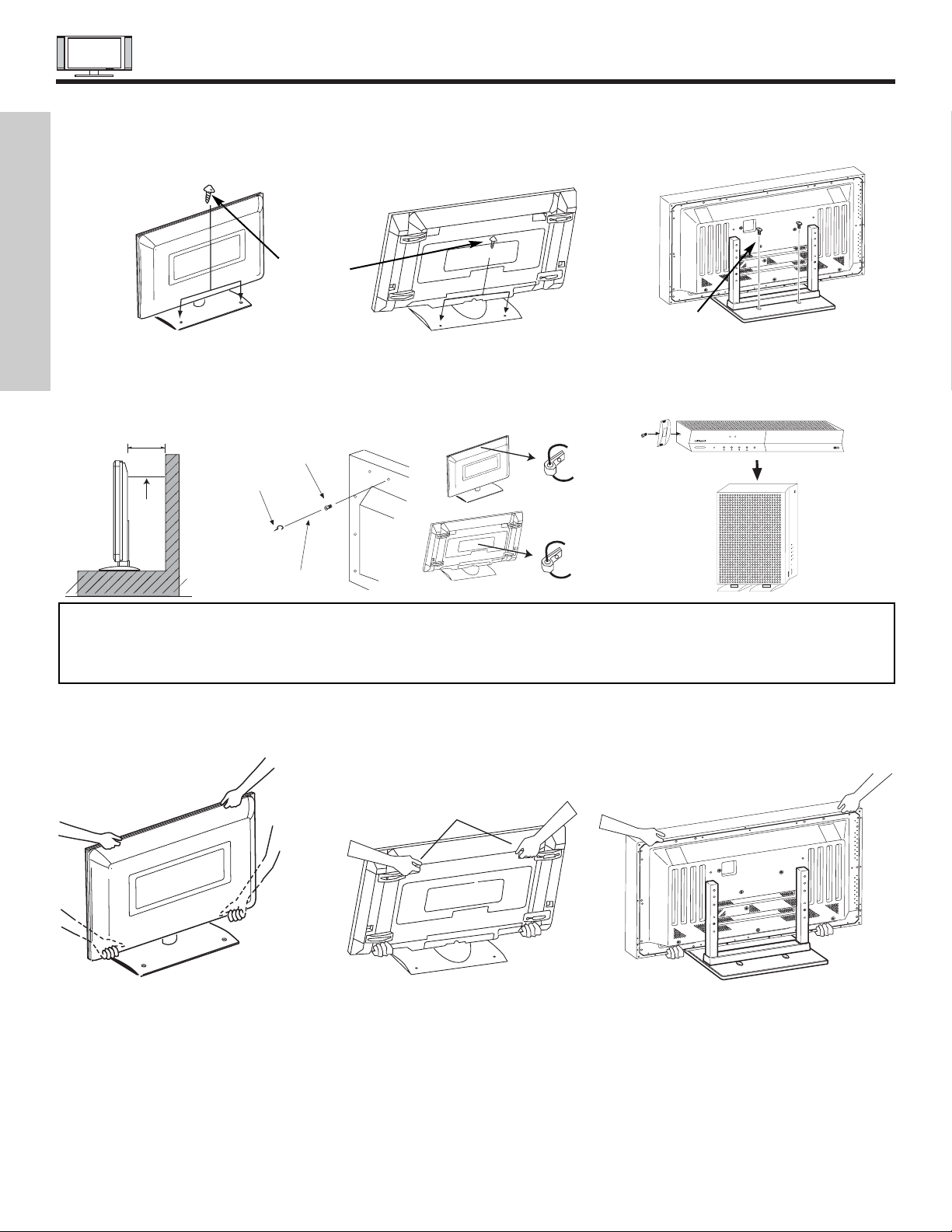
Securing to a table-top
1. Using wood screws (two) fasten the set to the clamping screw holes on the rear of the Plasma Display stand as shown below.
2. Using commercially available wood screws, secure the set firmly in position.
To take measures to prevent the Plasma Display from tipping over and prevent possible injury it is important to mount the unit
in a stable place.
Wood screw
two places
Caution when moving the main unit
As this product is heavy, whenever it is moved, two people are required to transport it safely. Whenever the unit is moved it should be
lifted forward using the two handgrips at the back for the 42”, and at the top and base on both sides of the 32” and 50” for stability . When
moving the Display Monitor, lift the handles and the bottom frame as shown below. Do not grab the speakers or the back cover when
lifting.
32"
Securing to a wall
1. Keep the Plasma Display monitor four inches away from the
wall except those hung to the wall mount bracket.
2. Secure the monitor to the wall as shown below.
10cm (4 inches) or more
Wire
NOTES: 1.
Do not block the ventilation holes of the Plasma Display monitor or the AVC center. Blocking the ventilation holes might cause fire
or defect.
2. The plasma television has two AC cords, one on the AVC center and the other on the Plasma Display monitor. In case of an
abnormal symptom, unplug both AC cords.
3. If you purchased the wall mount bracket option, please ask for professional installer. Do not install by yourself.
32”
42”
ANTENNA
Unless your Plasma Television is connected to a cable TV system or to a centralized antenna system, a good outdoor color TV antenna
is recommended for best performance. However, if you are located in an exceptionally good signal area that is free from interference
and multiple image ghosts, an indoor antenna may be sufficient.
LOCATION
Select an area where sunlight or bright indoor illumination will not fall directly on the picture screen. Also, be sure that the location
selected allows a free flow of air to and from the perforated back cover of the set.
To avoid cabinet warping, cabinet color changes, and increased chance of set failure, do not place the TV where temperatures can
become excessively hot, for example, in direct sunlight or near a heating appliance, etc.
50”
Wood screw
two places
50”
42”
32”
Handgrips
AVC Vertical Position (Using AVC Stand)
1. Install AVC Stand with screws provided.
2. AVC ventilation holes should be facing out.
PULL
POWER
STANDBY (RED) ON (GREEN)
CH+CH-VOL+VOL- INPUT/EXIT
AUDIO VIDEO CONTROL CENTER
POWER
STANDBY (RED) ON (GREEN)
CH+CH-VOL+VOL- INPUT/EXIT
AUDIO VIDEO CONTROL CENTER
Stabilization bolts
(Provided)
String or Wire
Wood Screw
32”
42”
50”
FIRST TIME USE
42"
HOW TO SET UP YOUR NEW HITACHI PLASMA TELEVISION
7
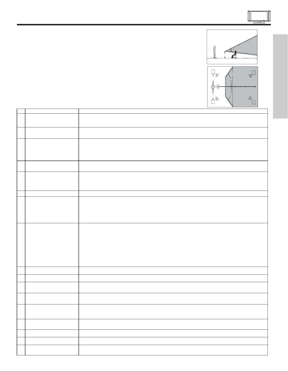
VIEWING
The major benefit of the HITACHI Plasma Television is its large viewing screen. To see this
large screen at its best, test various locations in the room to find the optimum spot for viewing.
The best picture is seen by sitting directly in front of the TV and about 8 to 18 feet from the
screen.
During daylight hours, reflections from outside light may appear on the screen. If so, drapes
or screens can be used to reduce the reflection or the TV can be located in a different section
of the room.
If the TV’s audio output will be connected to a Hi-Fi system’s external speakers, the best
audio performance will be obtained by placing the speakers equidistant from each side of the
receiver cabinet and as close as possible to the height of the picture screen center. For best
stereo separation, place the external speakers at least four feet from the side of the TV, place
the surround speakers to the side or behind the viewing area. Differences in room sizes and
acoustical environments will require some experimentation with speaker placement for best
performance.
A buzzing sound might be heard when the plasma display monitor is turned on in a very quiet
room. This is due to the plasma panel drive circuit when it is functioning. This arching sound
is normal and it is not a malfunction.
Some infrared rays are emitted from the plasma display monitor’s panel that might affect other
infrared controlling equipment.
High-precision technology is used to manufacture the plasma display panel; But in some
cases, there are minor defects in some parts of the screen. Points that do not light, points
with brightness different from that of the periphery, points with color different from that of the
periphery, etc. Some pixels will always be on or always off. Please note that this is not a
malfunction.
When receving still picture signals, (e.g. channel number indication or clock indication) for a
while, you can see image-like when the picture varied. This is not a defect.
The plasma display panel is lighting the phosphors by the discharge of internal radiation. In
some cases, this may cause the temperature of the panel surface to increase. Please note
that this is not a malfunction. The Plasma TV surface temperature is higher than a
Cathode-ray-tube.
The plasma panel is made from glass. Heavy shock on the front panel might damage it.
When the PDP monitor is transported horizontally, the glass panel has the possibility of being
broken or increasing the picture defects. At the time of transportation, horizontal style is
prohibited. More-over, please treat the plasma panel with great care because of a precision
apparatus. Please instruct transporters so that it should be put into the packing box at the time
of shipment.(There is a possibility that breakage of the panel or defects will increase.)
Rough transportation might cause damage to the panel and pixel failure.
The plasma monitor illuminates phosphor to display images. The phosphor has a finite
illumination life. After extended periods of illumination, the brightness of the phosphor will be
degraded to such extent that stationary images would burn-in that part of the screen as
grayed-out images. For 50” only, brightness will decrease automatically during still and slightly
moving pictures. This is not a failure. This is a special feature to avoid image retention.
Tips to prevent such image retention are:
- Do not display images having sharp brightness differences or hi-contrast images, such as
monochrome characters and graphic patterns, for long.
- Do not leave stationary images appearing for long, but try to refresh them at appropriate
intervals of time, or try to move them using screen saver function.
-Turn down the contrast and brightness controls.
PDP television has luminosity and low contrast compared with CRT television.
When a screen is seen at point-blank range, a random fine grain may be visible to a dark part.
If an apparatus (VCR, etc.) antenna line is arranged near the monitor, the image may shake,
or disturbance may be received.
There is some time lag betweeen the picture and the sound. You can see lip motion that is
delayed compared to the sound.
Electric discharge/luminescence characteristic of the PDP panel also changes with peripheral
temperature. Moreover, since there is also high power consumption value, a specified
temperature environment is required.
Storing the plasma television for a period of more than 2 to 3 months without use might cause
an unstable picture when the set is turned on.
Operating altitude: 800 to 1114hPa (6194ft to -2484ft). Operating temperature: 41˚F to 95˚F.
Storage Altitude: 300 to 1114hPa (15510ft to -2484ft). Storage temperature: 5˚F to 140˚F.
Frequent use of the Power ON or OFF might trigger the power protection circuit. If the TV
does not turn ON, please wait a little before turning ON again.
1 Arching sound from
plasma display monitor’s
panel.
2 Interference for infrared
equipment.
3 Bright and dark spots
4 Picture Image (Spectrum)
5 Display panel surface
temperature is too high
6 Plasma Surface
7Transportation
8 Image retention
9 Luminosity and contrast
10 Granular spots
11 Disturbance to video
apparatus
12 Lip Sync
13 About the use
environment of PDP
television (temperature)
14 Caution on prolonged
storage
15 Operating
16 Storage
17 Power ON or OFF
No. Items Notes
IMPORTANT NOTES
FIRST TIME USE
R
4" Minimum
4" Minimum
L
BEST
VERTICAL VIEWING
ANGLE
20
3’
0’
5’
50
5’
50
10’
BEST
HORIZONTAL
10’
VIEWING ANGLE
15’
20’
S
20’
15’
S
HOOKUP CABLES
8
FIRST TIME USE
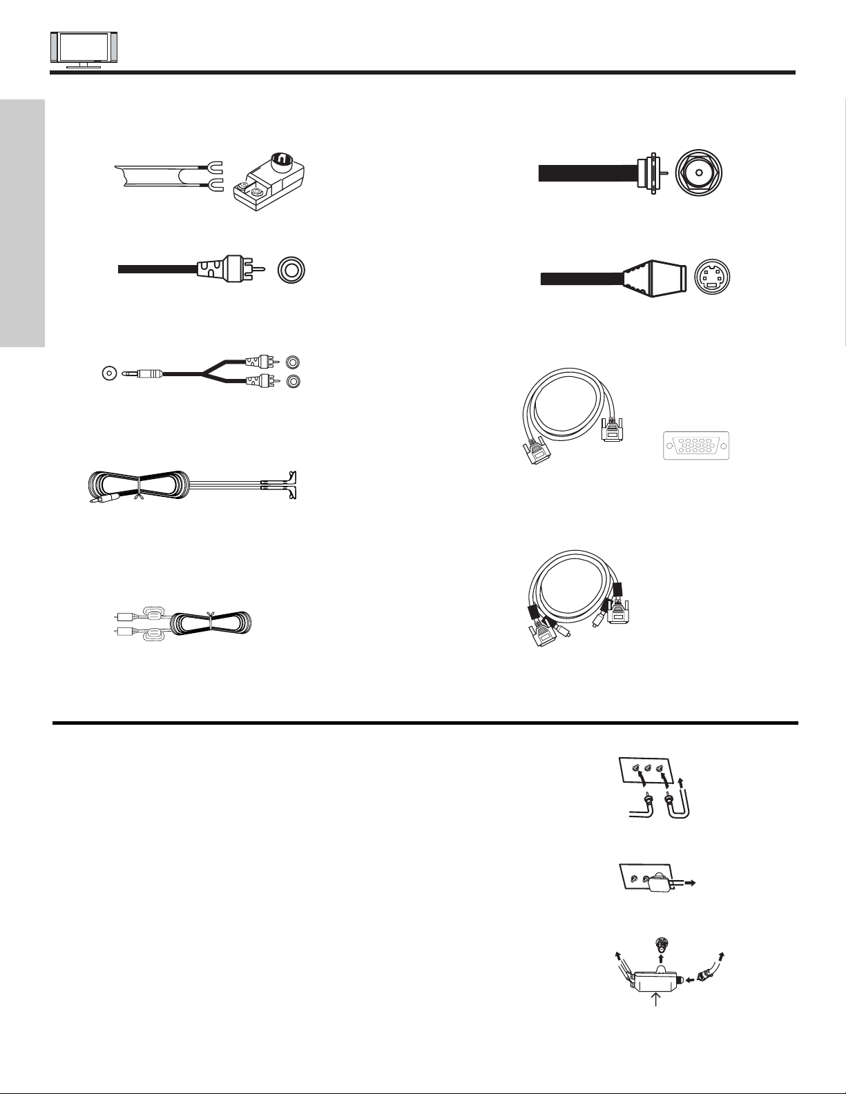
ANTENNA CONNECTIONS TO REAR JACK PANEL
VHF (75-Ohm) antenna/CATV (Cable TV)
When using a 75-Ohm coaxial cable system, connect the outdoor antenna or CATV
coaxial cable to the ANTA (75-Ohm) terminal. If you have a second antenna or cable TV
system, connect the coaxial cable to the ANT B terminal.
VHF (300-Ohm) antenna/UHF antenna
When using a 300-Ohm twin lead from an outdoor antenna, connect the VHF or UHF
antenna leads to screws of the VHF or UHF adapter. Plug the adapter into the antenna
terminal on the TV.
When both VHF and UHF antennas are connected
Attach an optional antenna cable mixer to the TV antenna terminal, and connect the
cables to the antenna mixer. Consult your dealer or service store for the antenna
mixer.
Most video/audio connections between components can be made with shielded video and audio cables that have phono connectors.
For best performance, video cables should use 75-Ohm coaxial shielded wire. Cables can be purchased from most stores that sell
audio/video products. Below are illustrations and names of common connectors. Before purchasing any cables, be sure of the output
and input connector types required by the various components and the length of each cable.
300-Ohm Twin Lead Connector
This outdoor antenna cable must be connected to an
antenna adapter (300-Ohm to 75-Ohm).
Phono Connector
Used on all standard video and audio cables which
connect to inputs and outputs located on the rear jack
panel and front control panel.
“F” Type 75-Ohm Coaxial Antenna Connector
For connecting RF signals (antenna or cable TV) to the
antenna jack on the television.
S-Video (Super Video) Connector
This connector is used on camcorders, VCRs and laserdisc players with an S-Video feature in place of the
standard video cable to produce a high quality picture.
Monitor Connection Cable (Provided)
This cable is used to connect the Display Monitor to the
AVC Center.
Stereo Cable (3.5 mm plug to 3.5 mm plug)
This cable is used to connect from external audio out to
the audio input of the AVC Center (ex. RGB Input).
IR Mouse Cable (Provided)
Connect the IR Mouse to the IR output on your AVC
center when A/V Network is used. You must place the
IR mouse in front of the corresponding IR window of
your cable box and VCR. This connection allows your
TV to control your cable box and VCR.
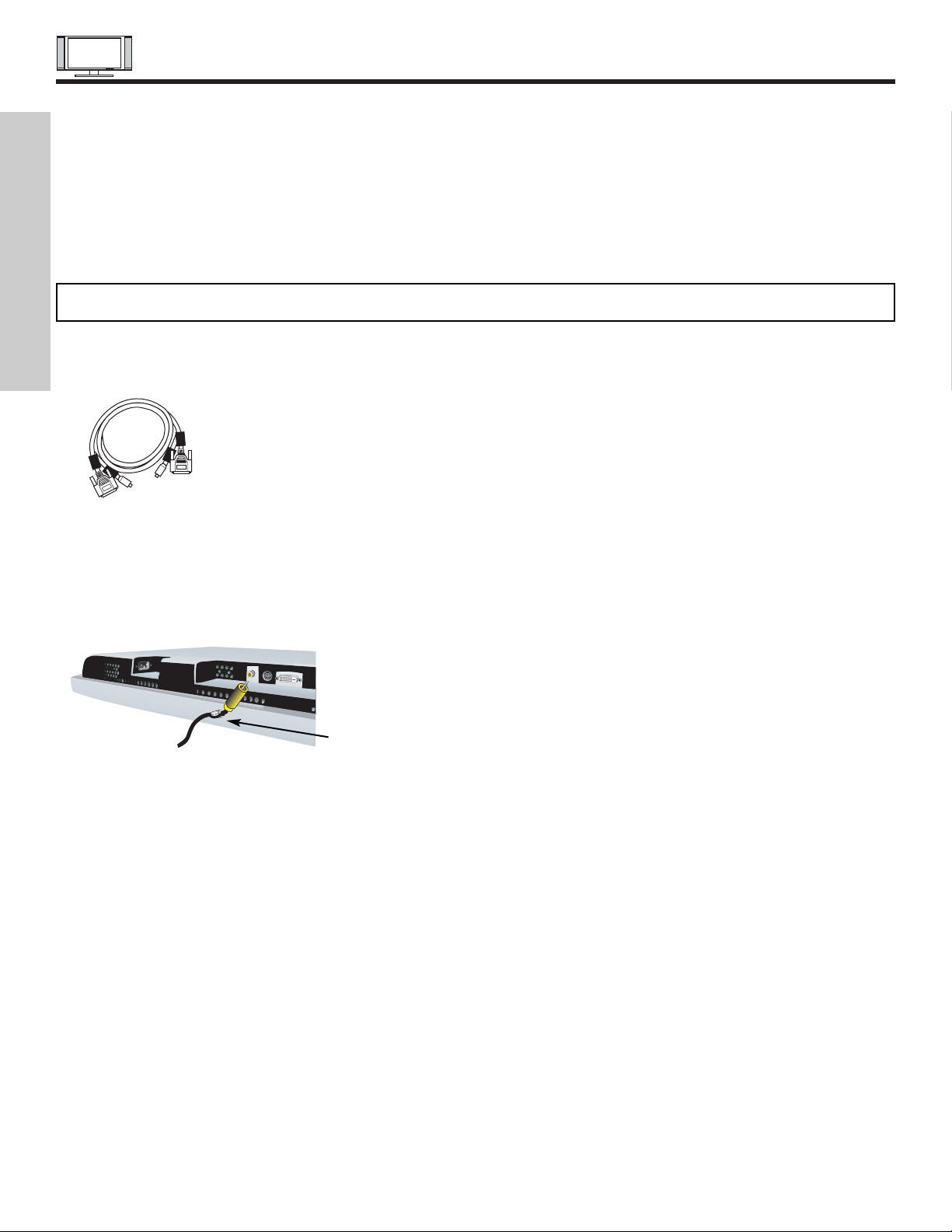
D-SUB MINI 15-Pin Cable
This cable is used to connect a computer output to the
D-SUB input located on the rear panel of the AVC
Center. The resolution should be set correctly to display
the signal on the Plasma Television.
Subwoofer Cable (Provided)
This cable is used to connect an external audio
component input to the subwoofer output of the Display
Monitor.
AUDIO OUT
3.8mm
STEREO
MINI-PLUG
2
RCA TYPE
PLUGS
12345
678910
1112131415
To outdoor antenna
or CATV cable
To UHF
antenna
ANT A/ANT B
Antenna Mixer
To second antenna
or cable system
To outdoor VHF
or UHF antenna
To outdoor antenna
or CATV system
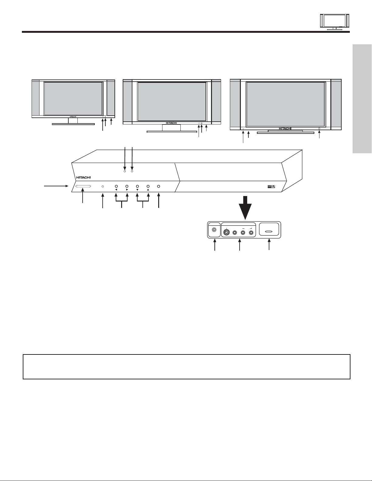
FRONT PANEL CONTROLS
9
FRONT VIEW
MENU/SELECT button
This button allows you to enter the MENU, making it possible to set TV features to your preference without using the remote. This
button also serves as the SELECT button when in MENU mode.
INPUT/EXIT button
Press this button to select the desired input, VIDEO 1 to 5, RGB, or Ant A/B source. Your selection is shown in the top right corner
of the screen. This button also serves as the EXIT button when in MENU mode.
CHANNEL selector
Press these buttons until the desired channel appears in the top right corner of the TV screen. These buttons also serve as
the cursor down () and up () buttons when in MENU mode.
VOLUME level
Press these buttons to adjust the sound level. The volume level will be displayed on the TV screen. These buttons also serve as
the cursor left () and right () buttons when in MENU mode.
32”
DISPLAY
MONITOR
AUDIO VIDEO
CONTROL
CENTER
42”
DISPLAY
MONITOR
STANDBY (RED) ON (GREEN)
MAIN POWER
STANDBY (RED) ON (GREEN)
MAIN POWER
50”
DISPLAY
MONITOR
STANDBY (RED) ON (GREEN)
PULL
POWER
MENU/SELECT
L/(MONO) R
VIDEO
S-VIDEO
INPUT 5
PHONES
AUDIO
STANDBY (RED) ON (GREEN)
CH+CH-VOL+VOL- INPUT/EXIT
AUDIO VIDEO CONTROL CENTER
NOTES: Your remote control does not have an INPUT button. To change to video inputs, press VID1~VID5 buttons depending
on the input you wish to switch to (see page 31). Press TV/RGB button on the remote control to toggle between TV
and RGB (ANALOG INPUT).
FIRST TIME USE
FRONT PANEL CONTROLS
10
FIRST TIME USE
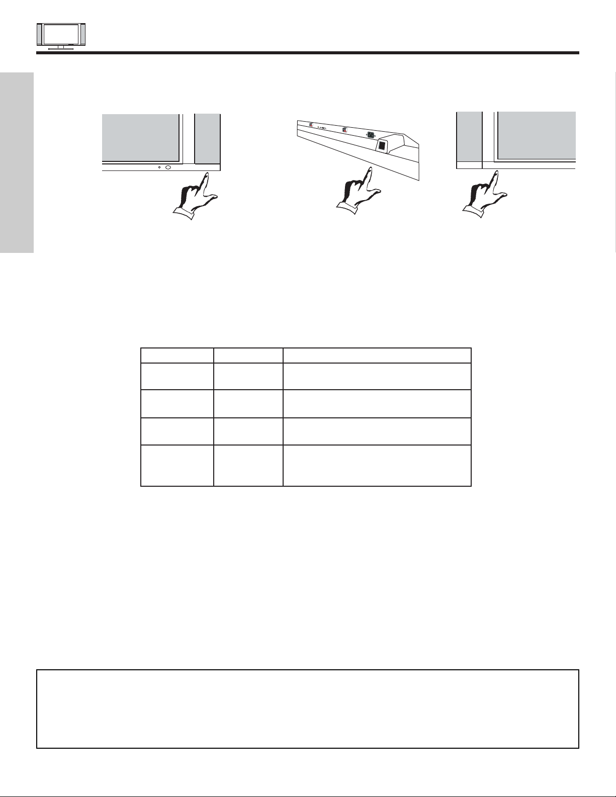
POWER button
Display Monitor “MAIN POWER” button
This power button is for the complete system, and must be turned ON/OFF manually. It is recommended to leave the “MAIN
POWER” to ON condition (lights red) for stand-by mode.
AVC POWER button
The AVC power can be turned ON/OFF manually or by remote control. Turning on the AVC Power will only turn on the AVC box if
the “MAIN POWER” of the display monitor is off.
POWER light indicator
To turn the monitor ON, press the main power switch located on the lower right side of the monitor (lower left for 50”). A red standby indicator lamp located on the lower right corner of the front bezel will illuminate (lower left for 50”). The PDP is now ready for
remote on/off operation.
REMOTE CONTROL sensor
Point your remote at this area when selecting channels, adjusting volume, etc.
FRONT INPUT JACKS (for VIDEO: 5)
Use these audio/video jacks for a quick hook-up from a camcorder or VCR to instantly view your favorite show or new recording.
press the VID5 button on the remote control button and VIDEO: 5 appears in the top right corner of the TV screen. If you have
mono sound, insert the audio cable into the left audio jack.
PHONES JACK
Use this jack for your head-phones. The TV’s internal speakers can also be heard. Turn off the internal speakers (see page 48) if
you wish to listen to the head-phones only.
LEARNING AV NET Sensor
Point your equipment’s remote control at this area while using the AV NET Learning Wizard.
NOTES: 1. Your HITACHI Plasma TV will appear to be turned OFF (lights orange) if there is no video input when VIDEO: 1, 2,
3, 4, 5, or RGB is selected. Check the Power Light to make sure the Display Monitor is turned off or in Stand-by
mode (lights red) when not in use.
2. Remote Control can not turn ON/OFF the “MAIN POWER” of the display monitor.
32”/42”
50”
MAIN POWER
or
TANDBY (RED) ON (GREEN)
MAIN POWER
Indicating Lamp Power Status Operating
Off Off When the main power switch is set
OFF.
Lights Red Off When the main power switch on the display
(Stand-by) monitor is ON, and the AVC Center is OFF.
Lights Green On Display monitor MAIN POWER is ON and
AVC Center power is ON.
Lights Orange Off Display monitor MAIN POWER is ON and
(Flashing) (Power Saving) and AVC Center power is ON, with no signal
input except antenna (no sync. signal).
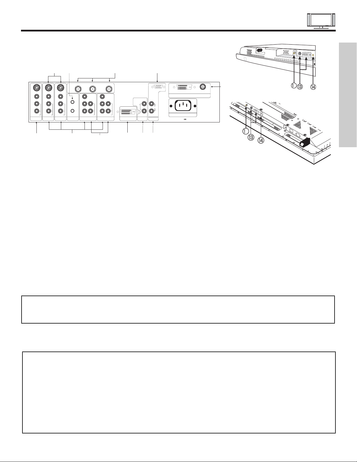
REAR PANEL JACKS
11
FIRST TIME USE
Component: Y-P
BPR
Inputs
Inputs 1 and 2 provide Y-P
BPR
jacks for connecting equipment with this capability, such as a DVD player or Set Top Box. You may
use composite video signal for INPUT 2. INPUT 1 does not accept composite video signal.
NOTES: 1. DO NOT connect composite VIDEO and S-VIDEO to Input 3, 4 or 5 at the same time. S-Video has a higher priority
over video input.
2. Your component outputs may be labeled Y, B-Y, and R-Y. In this case, connect the components B-Y output to the AVC
Box’s PBinput and the components R-Y output to the AVC Box’s PRinput.
3. Your component outputs may be labeled Y-CBCR. In this case, connect the component CBoutput to the AVC Box’s
PBinput and the component CRoutput to the AVC Box’s PRinput.
4. It may be necessary to adjust TINT to obtain optimum picture quality when using the Y-PBPR inputs (See page 45).
5. To ensure no copyright infringement, the MONITOR OUToutput will be abnormal, when using the Y -PBPRjacks, RGB
and DVI-HDTV inputs.
Antenna Input/Output
The remote control allows you to switch between two separate 75-Ohm RF antenna inputs, ANTA and ANT B. ANTA input can
be displayed as a main picture or sub-picture. ANT B can only be displayed as a main picture (ANT B cannot be displayed as a
sub-picture). The antenna output labeled “TO CONVERTER” allows the ANT A connection to pass directly to a different source
such as a cable box, only when ANT B is displayed as a main picture.
Audio/Video Inputs 1, 2, 3 and 4
The VID1~VID4 buttons will select each video source each time they are pressed. Use the audio and video inputs to connect
external devices, such as VCRs, camcorders, laserdisc players, DVD players etc. (if you have mono sound, insert the audio cable
into the left audio jack).
MONITOR OUT
These jacks provide fixed audio and video signals (ANTA/B, INPUT2~5) which are used for recording. Use the S-VIDEO Output
for high quality video output. Component signal to Input 1 and 2, RGB and DVI-HDTV inputs will not have monitor output.
AUDIO OUT
These jacks provide fixed audio output for all audio sources (ANT A/B, INPUT1~5, and RGB) to a separate stereo amplifier.
S-VIDEO Inputs 3 and 4
Inputs 3 and 4 provide S-VIDEO (Super Video) jacks for connecting equipment with S-VIDEO output capability.
REAR PANEL OF THE AVC CENTER
P
B
P
R
P
B
P
R
Y/VIDEO
R
L/(MONO)
AUDIO
L
R
S-VIDEO
VIDEO
AUDIO
R
S-VIDEO
VIDEO
AUDIO
R
S-VIDEO
VIDEO
MONITOR OUT INPUT 4 INPUT 3 IR BLASTER
L/(MONO)L/(MONO)
AUDIO
Y
R
L/(MONO)
AUDIO
INPUT 2 INPUT 1
ANT B
TO CONVERTER
ANT A
DVI-HDTV
INPUT 1
L
AUDIO
R
AUDIO OUT
ANALOG INPUT
L/(MONO)
R
AUDIO
RGB
TruBass SRS and symbol are trademarks of SRS Labs, Inc.
AC IN
TO MONITOR
Please use HITACHI specified cable.
NOTES: 1. You may use VIDEO or S-VIDEO inputs to connect to INPUT 3 and 4, but only one of these inputs may be used at a
time.
2. S-VIDEO output may be used for recording, only when the input is of S-VIDEO type.
2
32”/42” Monitor Bottom View
50” Monitor Bottom View
2
REAR PANEL JACKS
12
RGB - Analog Input
Use this 15-pin D-Sub input for your external devices with RGB output (see page 22).
RGB - Audio Input
Connect audio for RGB input (if you have mono sound, insert the audio cable into the left audio jack).
DVI - HDTV - Digital Input
Use this DVI Digital input for your external devices with digital output capability, such as a Set-Top-Box, high band DTV decoders
and DVD players with digital content protection (see page 22). DVI is INPUT 1 and has priority over component input. When DVI
is used, hook up audio to INPUT 1.
To Monitor
Connect the Monitor Connection Cable to the AVC center’s “TO MONITOR” connector, and to the display monitor’s “FROM AVC”
connector.
IR Blaster
This jack provides IR output to your external components (VCR, Cable box, DVD player, etc.). With this connection, your external
components can automatically be controlled by the A/V network feature. This connection will allow you to control the external
components with your Plasma Television’s remote control in TV mode.
Subwoofer Out
Connect this SUB WOOFER OUT output to the external audio component input using the sub woofer cable provided.
Sub-woofer cable (RCA Type)
To AVC
Connect the Monitor Connection cable from the AVC center’s “TO MONITOR” to these connectors (“FROM AVC”).
SUB-POWER button
This power is for serviceman usage.
FIRST TIME USE
Ferrite Core
NOTE: When using a Set-Top-Box, it is recommended to use a 1080i or 720p input signal.
CONNECTING PLASMA DISPLAY MONITOR TO AVC BOX
13
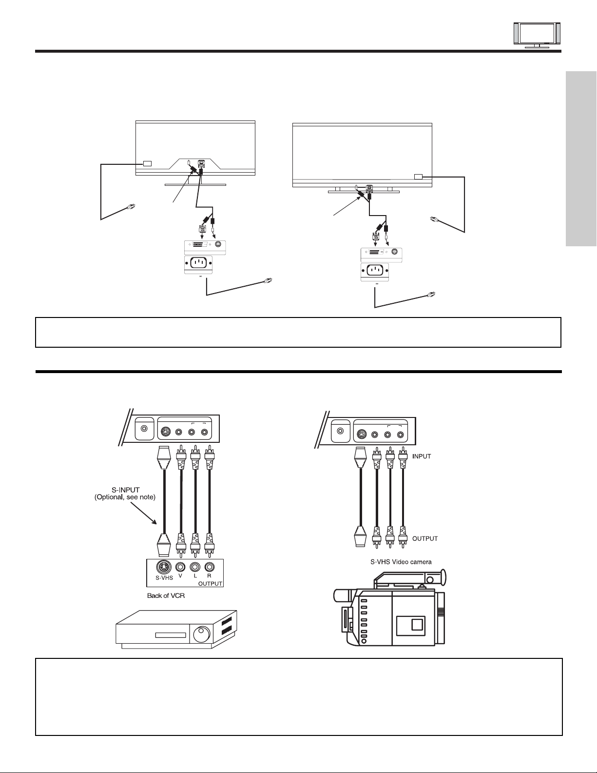
The front panel jacks are provided as a convenience to allow you to easily connect a camcorder or VCR as shown in the following
examples:
NOTES: 1. Completely insert connection cord plugs when connecting to front panel jacks. If you do not, the played back picture
may be abnormal.
2. If you have a S-VHS VCR, use the S-INPUT cable in place of the standard video cable.
3. If you have a mono VCR, insert the audio cable into the left audio jack of your AVC box.
4. S-VIDEO input takes priority over VIDEO input.
5. If you have a VHS or 8mm camcorder, use the S-VIDEO cable in place of the VIDEO cable.
PHONES
Front panel of AVC
PHONES
L/(MONO) R
VIDEO
S-VIDEO
INPUT 5
AUDIO
Front panel of AVC
L/(MONO) R
VIDEO
S-VIDEO
INPUT 5
AUDIO
CONNECTING EXTERNAL VIDEO SOURCES
1. From the owner’s accessory you will find the Monitor Connector cable.
2. Firmly, and securely insert the Monitor Connection Cable to the rear panel of the AVC box “TO MONITOR” connectors.
3. Insert the other ends of the Monitor Connection Cable to the display monitor rear panel “FROM AVC” connectors.
Back of AVC Center
To AC
outlet
To AC
outlet
Core
Back of AVC Center
To AC
outlet
To AC
outlet
Core
TruBass SRS and symbol are trademarks of SRS Labs, Inc.
AC IN
TO MONITOR
Please use HITACHI specified cable.
TruBass SRS and symbol are trademarks of SRS Labs, Inc.
AC IN
TO MONITOR
Please use HITACHI specified cable.
Back of Display Monitor
50”
Back of Display Monitor
32/42”
NOTE: The Display Monitor and the AVC Center have their own AC Power. Both AC cords must be completely plugged in to
the AVC Center and the display monitor, then plug them in to the AC outlets.
FIRST TIME USE
CONNECTING EXTERNAL VIDEO SOURCES
14
The exact arrangement you use to connect the VCR, camcorder, laserdisc player, DVD player, or HDTV Set Top Box to your Plasma
TV is dependent on the model and features of each component. Check the owner’s manual of each component for the location of
video and audio inputs and outputs.
The following connection diagrams are offered as suggestions. However, you may need to modify them to accommodate your
particular assortment of components and features. For best performance, video and audio cables should be made from coaxial
shielded wire.
Before Operating External Video Source
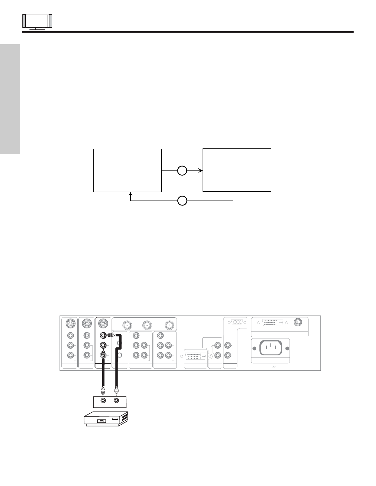
The input mode is changed when the VID1~VID5 button is pressed as shown below. Connect an external source to the INPUT
terminal, then press the VID1~VID5 button as necessary to view the input source (see page 31).
INPUT MODE SELECTION ORDER
(ANTENNA)
(INPUT)
VID1
ANT
3:32 PM
Ant A 32
Stereo
3:32 PM
YPBPR:1
VID1
Stereo
1080i Format
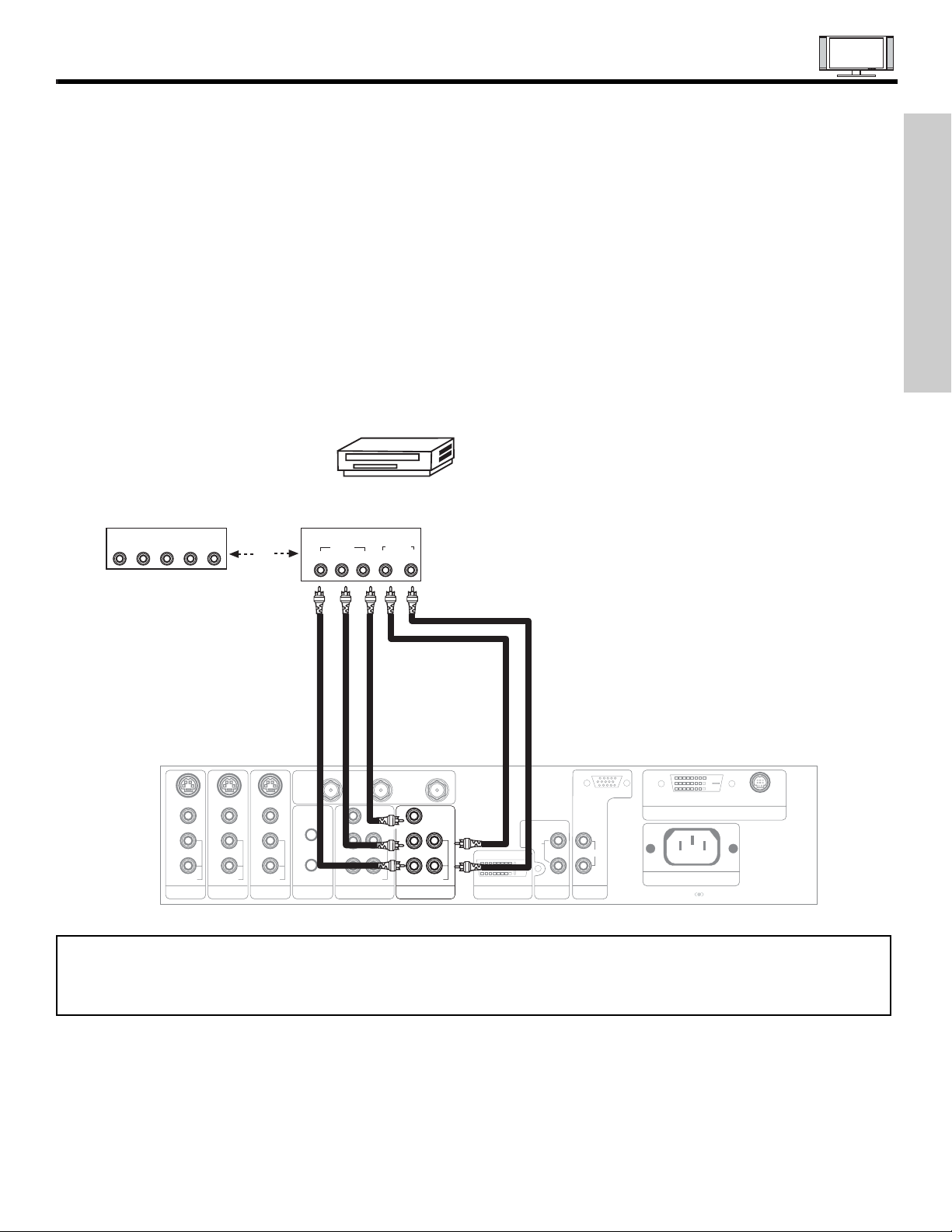
CONNECTING A MONAURAL AUDIO SOURCE TO INPUT2~INPUT5
1. Connect the cable from the VIDEO OUT of the VCR or the laserdisc player to the INPUT (VIDEO) jack, as shown on the AVC
Center below.
2. Connect the cable from the AUDIO OUT of the VCR or the laserdisc player to the INPUT (MONO)/L(AUDIO) jack.
3. Press the VID2~VID5 button to view the program from the VCR or the laserdisc player. The VIDEO mode disappears
automatically after approximately four seconds.
4. Press the ANT button to return to the previous channel.
P
B
P
R
P
B
P
R
DVI-HDTV
INPUT 1
L
AUDIO
R
AUDIO OUT
ANALOG INPUT
L/(MONO)
R
AUDIO
RGB
TruBass SRS and symbol are trademarks of SRS Labs, Inc.
Rear Panel of AVC Center
L/(MONO)
INPUT 3 IR BLASTER
AUDIO
VIDEO OUT
AUDIO OUT
VCR
Y/VIDEO
R
L/(MONO)
AUDIO
L
R
S-VIDEO
VIDEO
AUDIO
R
S-VIDEO
VIDEO
R
S-VIDEO
VIDEO
MONITOR OUT INPUT 4
L/(MONO)
AUDIO
Y
R
L/(MONO)
AUDIO
INPUT 2 INPUT 1
ANT B
TO CONVERTER
ANT A
AC IN
TO MONITOR
Please use HITACHI specified cable.
Back of VCR
FIRST TIME USE
CONNECTING EXTERNAL VIDEO SOURCES
15
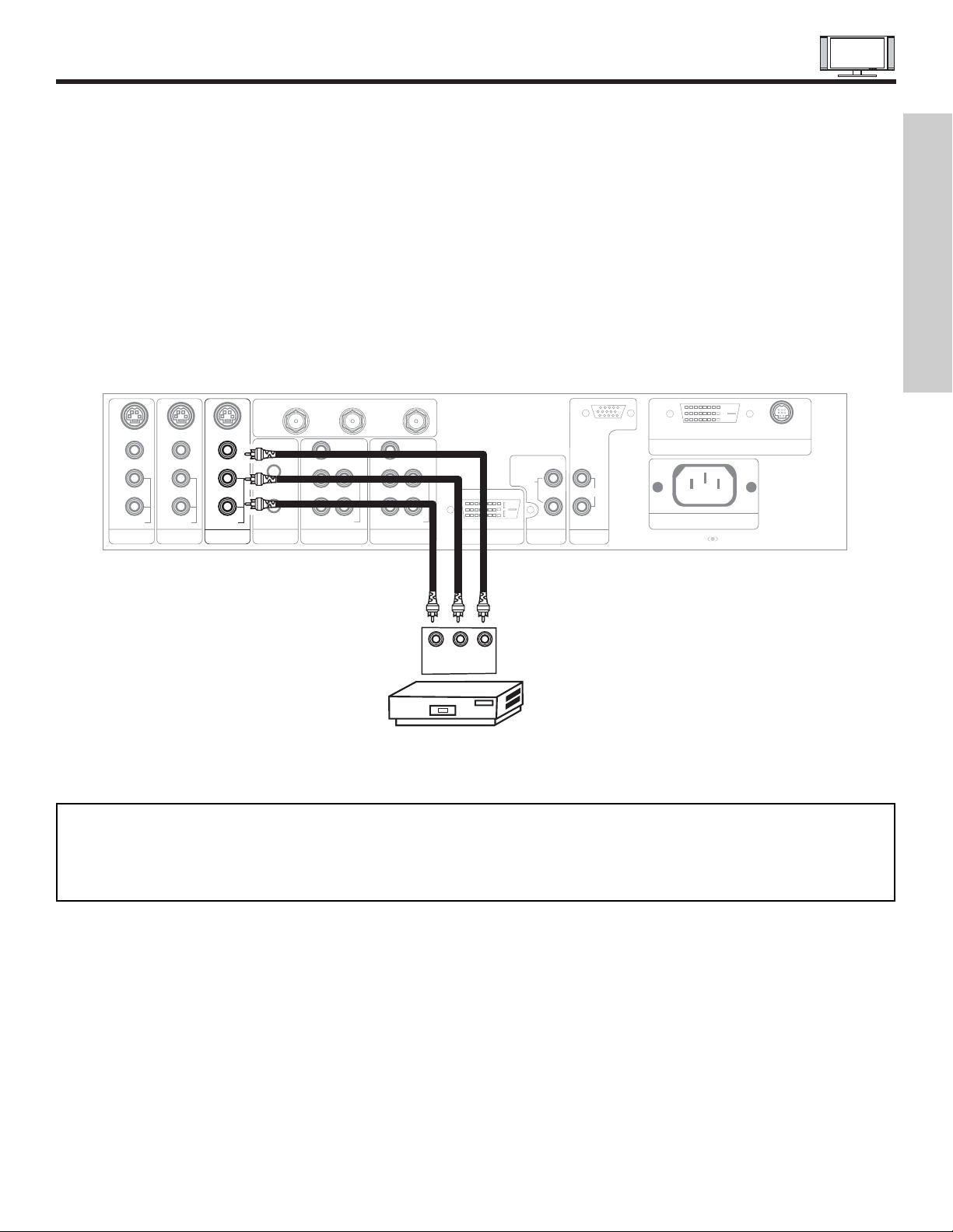
CONNECTING A STEREO VCR OR STEREO LASERDISC PLAYER
1. Connect the cable from the VIDEO OUT of the VCR or the laserdisc player to the INPUT (VIDEO) jack, as shown on the AVC
Center below.
2. Connect the cable from the AUDIO OUT R of the VCR or the laserdisc player to the INPUT (AUDIO/R) jack.
3. Connect the cable from the AUDIO OUT L of the VCR or the laserdisc player to the INPUT (AUDIO/L) jack.
4. Press the VID2~VID5 button to view the program from the VCR or laserdisc player. The VIDEO labeldisappears automatically
after approximately four seconds.
5. Press the ANT button to return to the previous channel.
P
B
P
R
P
B
P
R
DVI-HDTV
INPUT 1
L
AUDIO
R
AUDIO OUT
ANALOG INPUT
L/(MONO)
R
AUDIO
RGB
TruBass SRS and symbol are trademarks of SRS Labs, Inc.
AC IN
TO MONITOR
Please use HITACHI specified cable.
Rear Panel of AVC Center
Back of
VCR
R L V
VCR
OUTPUT
Y/VIDEO
R
L/(MONO)
AUDIO
L
R
S-VIDEO
VIDEO
AUDIO
R
S-VIDEO
VIDEO
AUDIO
R
S-VIDEO
VIDEO
MONITOR OUT INPUT 4 INPUT 3 IR BLASTER
L/(MONO)L/(MONO)
AUDIO
Y
R
L/(MONO)
AUDIO
INPUT 2 INPUT 1
ANT B
TO CONVERTER
ANT A
NOTES: 1. Completely insert the connection cord plugs when connecting to rear panel jacks. The picture and sound that is
played back will be abnormal if the connection is loose.
2. A single VCR can be used for VCR #1 and VCR #2, but note that a VCR cannot record its own video or line output
(INPUT: 4 in example on page 22). Refer to your VCR operating guide for more information on line input-output
connections.
FIRST TIME USE
16
CONNECTING EXTERNAL VIDEO SOURCES
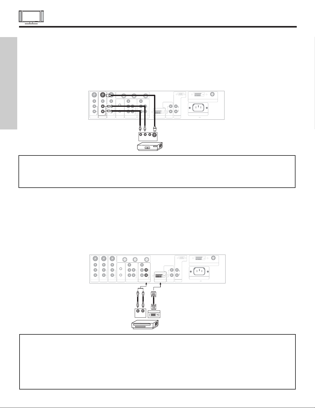
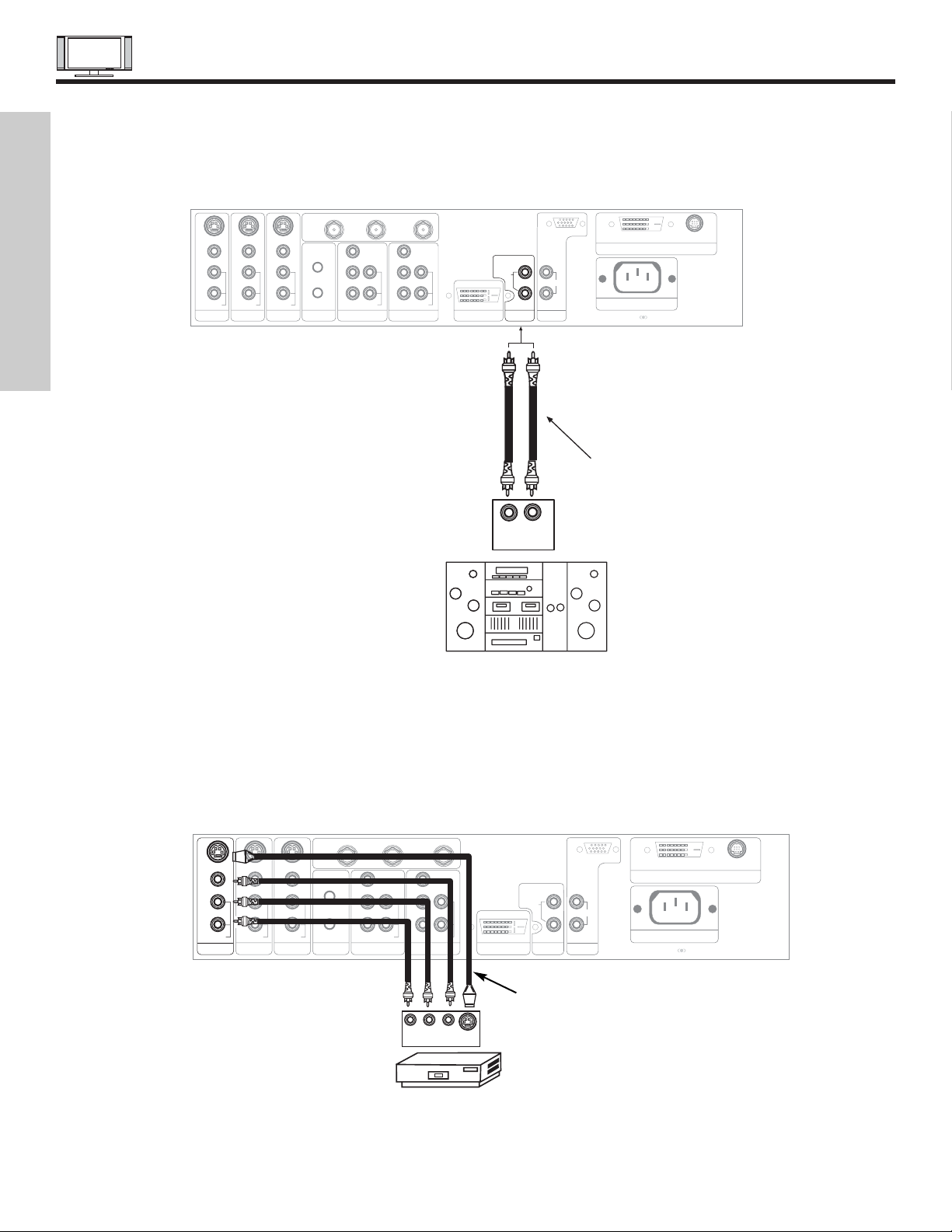
CONNECTING S-VIDEO VCR OR LASERDISC PLAYER
1. Connect the cable from the S-VIDEO OUT of the S-VHS VCR or the laserdisc player to the INPUT (S-VIDEO) jack, as shown
on the AVC Center below.
2. Connect the cable from the AUDIO OUT R of the VCR or the laserdisc player to the INPUT (AUDIO/R) jack.
3. Connect the cable from the AUDIO OUT L of the VCR or the laserdisc player to the INPUT (AUDIO/L) jack.
4. Press the VID3~VID5 button to view the program from the VCR or laserdisc player. The VIDEO label disappears automatically
after approximately four seconds.
5. Press the ANT button to return to the previous channel.
NOTES: 1. Completely insert the connection cord plugs when connecting to rear panel jacks. The picture and sound that is
played back will be abnormal if the connection is loose.
2. A single VCR can be used for VCR #1 and VCR #2, but note that a VCR cannot record its own video or line output
(INPUT: 4 in example on page 22). Refer to your VCR operating guide for more information on line input-output
connections.
P
B
P
R
P
B
P
R
DVI-HDTV
INPUT 1
L
AUDIO
R
AUDIO OUT
ANALOG INPUT
L/(MONO)
R
AUDIO
RGB
TruBass SRS and symbol are trademarks of SRS Labs, Inc.
AC IN
TO MONITOR
Please use HITACHI specified cable.
Rear Panel of AVC Center
S-VIDEO
R L V
VCR or Laserdisc Player
OUTPUT
Back of VCR or
Laserdisc Player
Y/VIDEO
R
L/(MONO)
AUDIO
L
R
S-VIDEO
VIDEO
AUDIO
R
S-VIDEO
VIDEO
AUDIO
R
S-VIDEO
VIDEO
MONITOR OUT INPUT 4 INPUT 3 IR BLASTER
L/(MONO)L/(MONO)
AUDIO
Y
R
L/(MONO)
AUDIO
INPUT 2 INPUT 1
ANT B
TO CONVERTER
ANT A
FIRST TIME USE
CONNECTING A COMPONENT SOURCE WITH DVI-HDTV CAPABILITY TO INPUT 1
1. Connect the DVI connection cable from the output of the HDTV set top box or DVD player to the DVI-HDTV input as shown on
the AVC Center below.
2. Connect the cable from the AUDIO OUT R of the HDTV set top box or DVD player to the INPUT (AUDIO/R) jack.
3. Connect the cable from the AUDIO OUT L of the HDTV set top box or DVD player to the INPUT (AUDIO/L) jack.
4. Press the VID1 button to view the program from the HDTV set top box or DVD player. The VIDEO OSD label disappears
automatically after approximately four seconds.
5. Press the ANT button to return to the previous channel.
NOTES: 1. Completely insert the connection cord plugs when connecting to rear panel jacks. The picture and sound that is
played back will be abnormal if the connection is loose.
2. The DVI-HDTV input on INPUT 1 contains the copy protection system called High-bandwidth Digital Content
Protection (HDCP). HDCP is a cryptographic system that encrypts video signals when using DVI connections to
prevent illegal copying of video contents.
3. DVI is not a “NETWORK” technology. It establishes a one-way point-to-point connection for delivery of
uncompressed video to a display.
4. The connected digital output device controls the DVI interface so proper set-up of device user settings determines
final video appearance.
P
B
P
R
P
B
P
R
P
B
P
R
TruBass SRS and symbol are trademarks of SRS Labs, Inc.
AC IN
TO MONITOR
Please use HITACHI specified cable.
Rear Panel of AVC Center
LR
OUTPUT
D-VHS
Y/VIDEO
R
L/(MONO)
AUDIO
L
R
S-VIDEO
VIDEO
AUDIO
R
S-VIDEO
VIDEO
AUDIO
R
S-VIDEO
VIDEO
MONITOR OUT INPUT 4 INPUT 3 IR BLASTER
L/(MONO)L/(MONO)
AUDIO
Y
R
L/(MONO)
AUDIO
INPUT 2 INPUT 1
ANT B
TO CONVERTER
ANT A
DIGITAL OUTPUT
DVI-HDTV
INPUT 1
L
AUDIO
R
AUDIO OUT
ANALOG INPUT
L/(MONO)
R
AUDIO
RGB
Back of
D-VHS
17
CONNECTING EXTERNAL VIDEO SOURCES
CONNECTING A STEREO LASERDISC/DVD PLAYER OR HDTV SET TOP BOX TO INPUT 1 OR 2 COMPONENT: Y-PBPR.
1. Connect the cable from the Y OUT of the Laserdisc/DVD player or HDTV set top box to the INPUT (Y) jack, as shown on the
AVC Center below.
2. Connect the cable from the CB/PBOUT or B-Y OUT of the Laserdisc/DVD player or HDTV set top box to the INPUT (PB)jack.
3. Connect the cable from the CR/PROUT or R-Y OUT of the Laserdisc/DVD player or HDTV set top box to the INPUT (PR) jack.
4. Connect the cable from the AUDIO OUT R of the Laserdisc/DVD player or HDTV set top box to the INPUT (AUDIO/R) jack.
5. Connect the cable from the AUDIO OUT L of the Laserdisc/DVD player or HDTV set top box to the INPUT (AUDIO/L) jack.
6. Press the VID1/VID2 button, to view the program from the Laserdisc/DVD player or HDTV set top box. The VIDEO label
disappears automatically after approximately four seconds.
7. Press the ANT button to return to the previous channel.
P
B
P
R
P
B
P
R
DVI-HDTV
INPUT 1
L
AUDIO
R
AUDIO OUT
ANALOG INPUT
L/(MONO)
R
AUDIO
RGB
TruBass SRS and symbol are trademarks of SRS Labs, Inc.
AC IN
TO MONITOR
Please use HITACHI specified cable.
Rear Panel of AVC Center
L R
AUDIO
Y/VIDEO
L/(MONO)
AUDIO
OUTPUT
DVD Player
OR
Back of
DVD Player
OUTPUT
LR Y P
B
P
R
HDTV Set-Top Box
PR/CR PB/C
B Y
VIDEO
R
AUDIO
L
R
S-VIDEO
VIDEO
AUDIO
R
S-VIDEO
VIDEO
AUDIO
R
S-VIDEO
VIDEO
MONITOR OUT INPUT 4 INPUT 3 IR BLASTER
L/(MONO)L/(MONO)
Y
R
L/(MONO)
AUDIO
INPUT 2 INPUT 1
ANT B
TO CONVERTER
ANT A
NOTE: 1. Completely insert the connection cord plugs when connecting to rear panel jacks. The picture and sound that is
played back will be abnormal if the connection is loose.
2. See page 23 for tips on REAR PANELCONNECTIONS.
FIRST TIME USE
18
CONNECTING EXTERNAL AUDIO/VIDEO DEVICES
CONNECTING EXTERNAL AUDIO AMPLIFIER
To monitor the audio level of the Plasma TV to an external audio amplifier, connect the system as shown below. The “AUDIOOUT”
from the AVC center is a fixed output. The Volume of the amplifier is controlled by the amplifier, not by the Plasma Television. The
AUDIO OUT terminal outputs all audio sources (ANT A/B, INPUT 1~5 and RGB).
P
B
P
R
P
B
P
R
Y/VIDEO
R
L/(MONO)
AUDIO
L
R
S-VIDEO
VIDEO
AUDIO
R
S-VIDEO
VIDEO
AUDIO
R
S-VIDEO
VIDEO
MONITOR OUT INPUT 4 INPUT 3 IR BLASTER
L/(MONO)L/(MONO)
AUDIO
Y
R
L/(MONO)
AUDIO
INPUT 2 INPUT 1
ANT B
TO CONVERTER
ANT A
TruBass SRS and symbol are trademarks of SRS Labs, Inc.
AC IN
TO MONITOR
Please use HITACHI specified cable.
Rear Panel of AVC Center
To Audio Input Terminal
of External Amplifier
RL
INPUT
Stereo System Amplifier
DVI-HDTV
INPUT 1
L
AUDIO
R
AUDIO OUT
ANALOG INPUT
L/(MONO)
R
AUDIO
RGB
P
B
P
R
P
B
P
R
DVI-HDTV
INPUT 1
L
AUDIO
R
AUDIO OUT
ANALOG INPUT
L/(MONO)
R
AUDIO
RGB
TruBass SRS and symbol are trademarks of SRS Labs, Inc.
AC IN
TO MONITOR
Please use HITACHI specified cable.
Rear Panel of AVC Center
S-VIDEO
R L V
Y/VIDEO
R
L/(MONO)
AUDIO
R
VIDEO
AUDIO
R
S-VIDEO
VIDEO
INPUT 3 IR BLASTER
L/(MONO)L/(MONO)
AUDIO
Y
R
L/(MONO)
AUDIO
INPUT 2 INPUT 1
ANT B
TO CONVERTER
ANT A
VCR or other external
components
INPUT
AUDIO
L
R
S-VIDEO
VIDEO
S-VIDEO
MONITOR OUT INPUT 4
Optional,
See page 23
The MONITOR OUT terminal outputs video and audio of ANT A/B and INPUT2~5 only. It does not output component video, DVIHDTV or RGB. If a component device is input to INPUT2, no monitor out is available for this output.
FIRST TIME USE
CONNECTING AV NETWORK
19
Your Hitachi Plasma Television is equipped with an AV Network feature. This feature helps to control your external Audio/Video
equipment (VCR, Set Top Box, DVD, etc.). Once this is setup, it allows your IR Mouse connector to control your equipment using
your Hitachi Plasma TV Remote Control. You can use your Hitachi remote control to control the Audio/Video equipment command
without the equipment’s remote control.
The Plasma Television AVC Center has 2 IR BLASTER jacks. Each IR Mouse cable can connect up to 2 external Audio/Video
components. Therefore, you can connect the Plasma Television with up to four components. Please see the following example of
an AV Network setup between your Hitachi Plasma Television and external Audio/Video equipment (VCR and DVD Player).
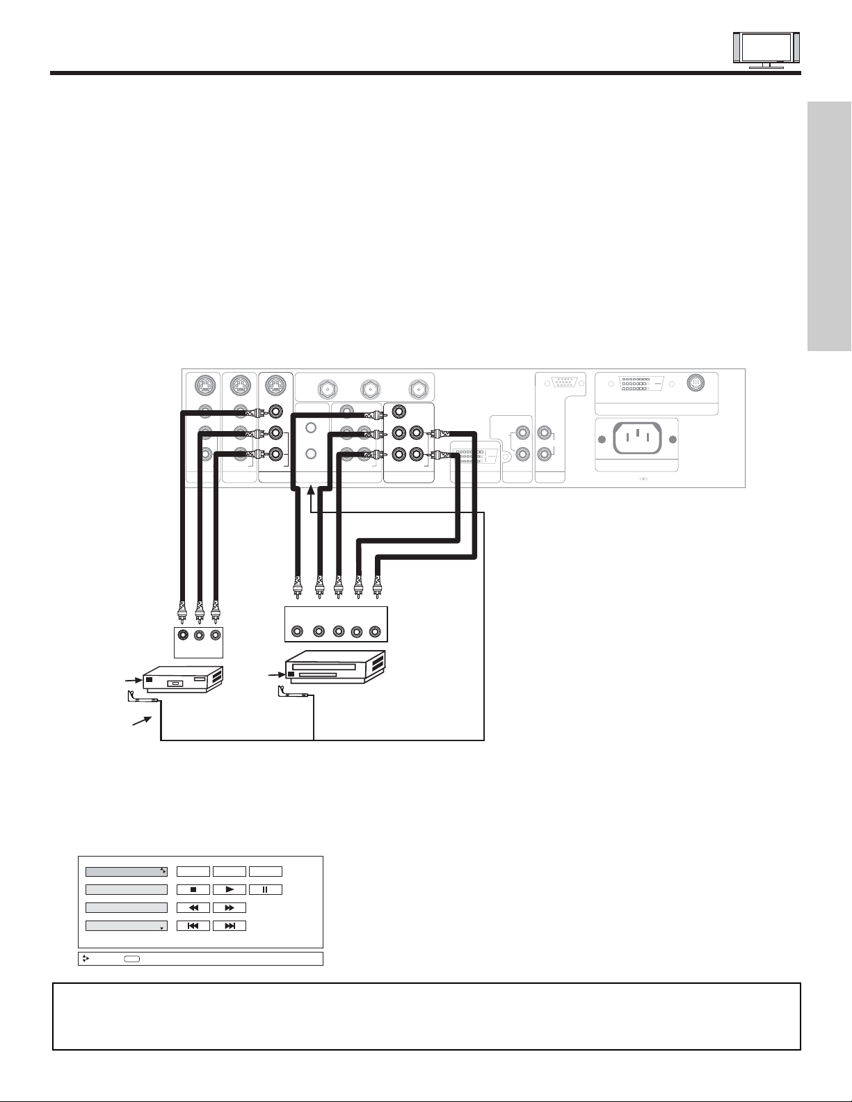
CONNECTING EXTERNAL AUDIO/VIDEO COMPONENTS TO IR BLASTER FOR AV NETWORK
1. Connect your external Audio/Video components to the AVC Center shown on pages 13~18.
2. Connect the IR Mouse cable to the IR BLASTER output of the AVC Center.
3. Place the IR mouse in front of the infrared sensor of the external components you wish to control.
4. Press the AV NET button on the remote control. Use THUMB STICK or to highlight the component you wish to set up.
Use THUMB STICK to enter component’s “SOFT KEY” control button. The AV Network Setup Wizard will automatically start
upon the very first use. You can access the Setup Menu Wizard again in the future by pressing the AV net button and then
pressing the INFO button.
NOTES: 1. The AVC Center has two IR BLASTER outputs which can control up to a total of four external components.
2. The IR Mouse must be placed in front of the external components infrared sensor for the AV Network to work.
3. The correct codes must be entered for each of the Audio/Video components for the AV Network to function properly.
4. Audio/Video component codes for AV network are on page 21.
P
B
P
R
P
B
P
R
DVI-HDTV
INPUT 1
L
AUDIO
R
AUDIO OUT
ANALOG INPUT
L/(MONO)
R
AUDIO
RGB
TruBass SRS and symbol are trademarks of SRS Labs, Inc.
AC IN
TO MONITOR
Please use HITACHI specified cable.
Rear Panel of AVC Center
Y/VIDEO
R
L/(MONO)
AUDIO
L
R
S-VIDEO
VIDEO
AUDIO
R
S-VIDEO
VIDEO
AUDIO
R
S-VIDEO
VIDEO
MONITOR OUT INPUT 4 INPUT 3 IR BLASTER
L/(MONO)L/(MONO)
AUDIO
Y
R
L/(MONO)
AUDIO
INPUT 2 INPUT 1
ANT B
TO CONVERTER
ANT A
DVD Player
AUDIO
R
V L R
OUTPUT
VCR
Infrared
Sensor
Infrared
Sensor
IR
Mouse
OUTPUT
YP
B/CBPR/CR
R L
AV Receiver
PV Recorder
VCR
DVD
Move
POWER MENU MORE
INFO
Device Setting
FIRST TIME USE
AV NETWORK SETUP WIZARD
20
FIRST TIME USE
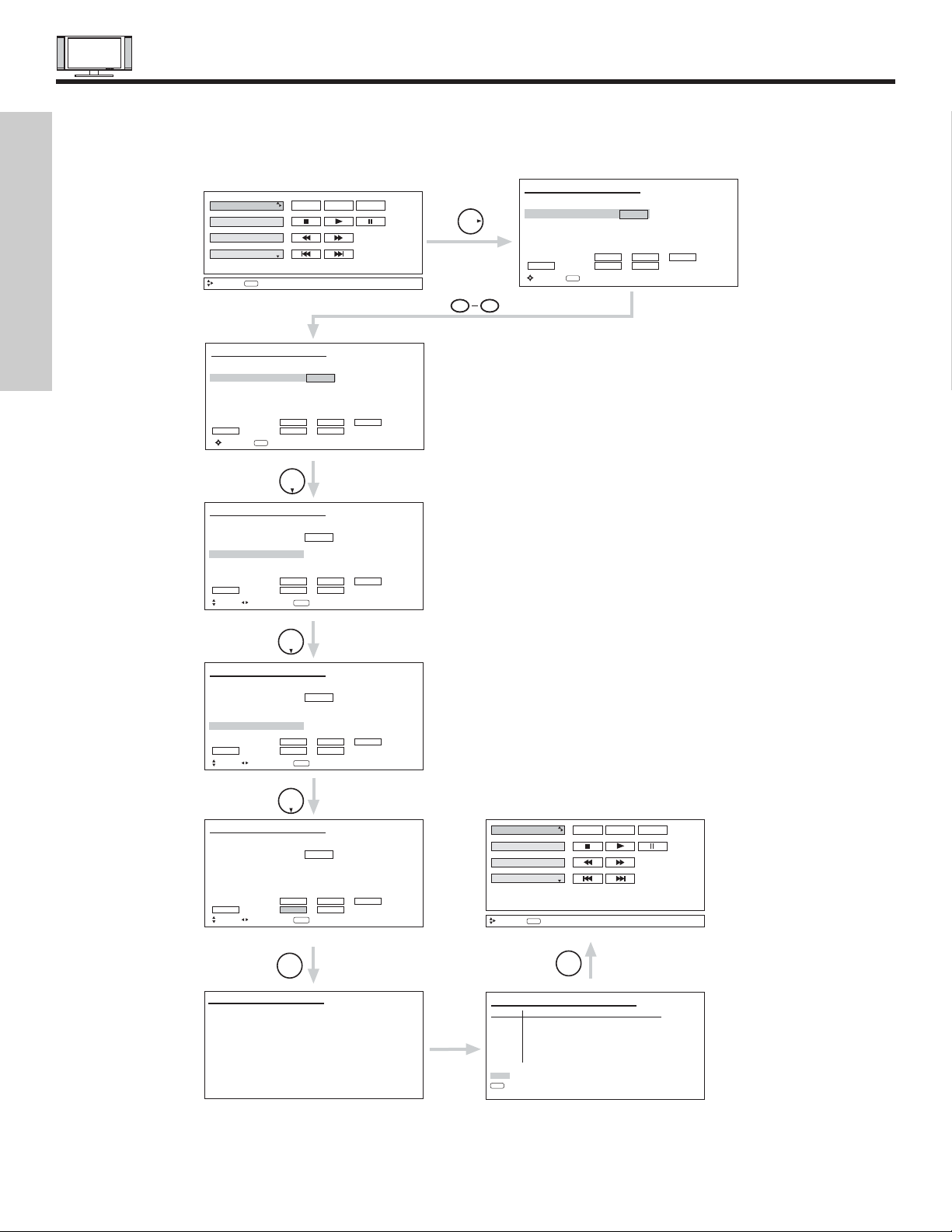
5. Follow the steps below to setup your AV network (See page 21 for AV Network Codes).
There are six steps in the setup procedure (DVD setup example below).
6. To uninstall or change device (equipment), press INFO button on the remote control when the device (DVD, VCR, etc.) is
highlighted.
7. See Remote Control AV NET button usage on pages 27 and 28.
Enter the device (equipment) code listed on page 21.
Use THUMBSTICK to select the input that the device (equipment)
is hooked-up to.
Transmission test for the device to confirm that the proper code was
set, by selecting (POWER, PLAY, etc.) soft keys shown. If the device
responds to the transmission test soft key, then it is properly set up.
Select OK to continue.
DVD
VCR
PV Recorder
AV Receiver
Move
INFO
HITACHI AV NET SET UP
DVD
Device Code 0 6 7 2
Video Input No Connection
Audio Input No Connection
Transmission Test POWER PLAY CH UP
BACK OK EXIT
Move
HITACHI AV NET SET UP
DVD
Device Code 0 6 7 2
Video Input Input 1
Audio Input No Connection
Transmission Test POWER PLAY CH UP
BACK OK EXIT
Move
POWER MENU MORE
Device Setting
(Enter code “9999” to uninstall)
0-9
Input
THUMB
STICK
(Enter code “9999” to uninstall)
Set Input
SEL Select
THUMB
STICK
Proper Code Entered
from page 21.
THUMB
STICK
HITACHI AV NET SET UP
DVD
Device Code - - - -
(Enter code “9999” to uninstall)
Video Input No Connection
Audio Input No Connection
Transmission Test POWER PLAY CH UP
BACK OK EXIT
Move
0-9
Input
90
HITACHI AV NET SET UP
DVD
Device Code 0 6 7 2
(Enter code “9999” to uninstall)
Video Input Input 1
Audio Input Using TV
Transmission Test POWER PLAY CH UP
BACK OK EXIT
Move
Set Input
SEL Select
THUMB
STICK
(x2)
HITACHI AV NET SET UP
DVD
Device Code 0 6 7 2
(Enter code “9999” to uninstall)
Video Input Input 1
Audio Input Using TV
Transmission Test POWER PLAY CH UP
BACK OK EXIT
Move
Set Input
SEL Select
THUMB
STICK
SELECT
HITACHI AV NET SET UP
Congratulations
Your DVD is now
connected to your AV network.
DVD
VCR
PV Recorder
AV Receiver
Move
INFO
HITACHI AV NET SETTING LIST
Device Code Video Audio
DVD 0672 INPUT 1 Using TV
VCR ---- Not Setup Not Setup
PVR ---- Not Setup Not Setup
AVR ---- Not Setup Not Setup
CBL ---- Not Setup Not Setup
STB ---- Not Setup Not Setup
Custom ---- Not Setup Not Setup
EXIT
SEL
Select
POWER MENU MORE
Device Setting
THUMB
STICK
SELECT

AUDIO/VIDEO CODES FOR AV NETWORK
(not for remote control)
21
VCR BRAND . . . . . . . . . . . . . . . . . . . . . . . . . . . CODE
Admiral. . . . . . . . . . . . . . . . . . . . . . . . . . . . 0048, 0209
Adventura . . . . . . . . . . . . . . . . . . . . . . . . . . . . . . .0000
Aiko . . . . . . . . . . . . . . . . . . . . . . . . . . . . . . . . . . . 0278
Aiwa. . . . . . . . . . . . . . . . . . . . . . . . . . . . . . 0000, 0037
Akai . . . . . . . . . . . . . . . . . . . . . . . . . . . . . . . . . . . 0041
America Action . . . . . . . . . . . . . . . . . . . . . . . . . . . 0278
American High . . . . . . . . . . . . . . . . . . . . . . . . . . . 0035
Asha . . . . . . . . . . . . . . . . . . . . . . . . . . . . . . . . . . 0240
Audiovox . . . . . . . . . . . . . . . . . . . . . . . . . . 0037, 0278
Beaumark. . . . . . . . . . . . . . . . . . . . . . . . . . . . . . . 0240
Bell & Howell . . . . . . . . . . . . . . . . . . . . . . . . . . . . 0104
Broksonic . . . . . . . . . . . . . . . . 0121, 0184, 0002, 0209,
. . . . . . . . . . . . . . . . . . . . . . . . . . . . . 0479, 1479, 0278
CCE . . . . . . . . . . . . . . . . . . . . . . . . . . . . . . 0072, 0278
Calix. . . . . . . . . . . . . . . . . . . . . . . . . . . . . . . . . . . 0037
Canon . . . . . . . . . . . . . . . . . . . . . . . . . . . . . . . . . 0035
Carver . . . . . . . . . . . . . . . . . . . . . . . . . . . . . . . . . 0081
Cineral . . . . . . . . . . . . . . . . . . . . . . . . . . . . . . . . . 0278
Citizen . . . . . . . . . . . . . . . . . . . . . . . 0278, 0037, 1278
Colt . . . . . . . . . . . . . . . . . . . . . . . . . . . . . . . . . . . 0072
Craig. . . . . . . . . . . . . . . . . . . . 0037, 0072, 0047, 0240
Curtis Mathes. . . . 0035, 0041, 0060, 0162, 0760, 1035
Cybernex . . . . . . . . . . . . . . . . . . . . . . . . . . . . . . . 0240
Daewoo . . . . . . . . . . . . . . . . . . . . . . 0278, 1278, 0045
Denon . . . . . . . . . . . . . . . . . . . . . . . . . . . . . . . . . 0042
Dynatech . . . . . . . . . . . . . . . . . . . . . . . . . . . . . . . 0000
Electrohome. . . . . . . . . . . . . . . . . . . . . . . . . . . . . 0037
Electrophonic . . . . . . . . . . . . . . . . . . . . . . . . . . . . 0037
Emerex . . . . . . . . . . . . . . . . . . . . . . . . . . . . . . . . 0032
Emerson . . . . . . . . . . . . . . . . . . . . . 0184, 0002, 0209,
. . . . . . . . . . . . . . . . . . . . . . . . 0121, 0000, 0037, 0043
Fisher . . . . . . . . . . . . . . . . . . . . . . . . . . . . . 0104, 0047
Fuji . . . . . . . . . . . . . . . . . . . . . . . . . . . . . . . 0033, 0035
Funai . . . . . . . . . . . . . . . . . . . . . . . . . . . . . . . . . . 0000
GE . . . . . . . 0035, 0060, 0240, 0760, 0807, 1035, 1060
Garrard . . . . . . . . . . . . . . . . . . . . . . . . . . . . . . . . 0000
Go Video . . . . . . . . . . . . . . . . . . . . . . . . . . . . . . . 0432
GoldStar . . . . . . . . . . . . . . . . . . . . . . 0037, 0038, 1237
Gradiente. . . . . . . . . . . . . . . . . . . . . . . . . . . . . . . 0000
HI-Q. . . . . . . . . . . . . . . . . . . . . . . . . . . . . . . . . . . 0047
Harley Davidson. . . . . . . . . . . . . . . . . . . . . . . . . . 0000
Harman/Kardon . . . . . . . . . . . . . . . . . . . . . 0038, 0081
Harwood . . . . . . . . . . . . . . . . . . . . . . . . . . . . . . . 0072
Hitachi . . . . . . . . . . . . . . . . . . . . . . . 0000, 0041, 0042
Hughes Network Systems. . . . . . . . . . . . . . . . . . . 0042
JVC . . . . . . . . . . . . . . . . . . . . . . . . . . . . . . 0067, 0041
Jensen. . . . . . . . . . . . . . . . . . . . . . . . . . . . . . . . . 0041
KEC . . . . . . . . . . . . . . . . . . . . . . . . . . . . . . 0037, 0278
KLH . . . . . . . . . . . . . . . . . . . . . . . . . . . . . . . . . . . 0072
Kenwood. . . . . . . . . . . . . . . . . . . . . . 0041, 0067, 0038
Kodak. . . . . . . . . . . . . . . . . . . . . . . . . . . . . 0035, 0037
LXI . . . . . . . . . . . . . . . . . . . . . . . . . . . . . . . . . . . . 0037
Lloyd's . . . . . . . . . . . . . . . . . . . . . . . . . . . . . . . . . 0000
Logik . . . . . . . . . . . . . . . . . . . . . . . . . . . . . . . . . . 0072
MEI . . . . . . . . . . . . . . . . . . . . . . . . . . . . . . . . . . . 0035
MGA. . . . . . . . . . . . . . . . . . . . . . . . . . . . . . 0043, 0240
MGN Technology . . . . . . . . . . . . . . . . . . . . . . . . . 0240
MTC. . . . . . . . . . . . . . . . . . . . . . . . . . . . . . 0000, 0240
Magnasonic . . . . . . . . . . . . . . . . . . . . . . . . . . . . . 1278
Magnavox . . . . . . . . . . . . . . . . . . . . 0035, 0081, 0563,
. . . . . . . . . . . . . . . . . . . . . . . . 0000, 0039, 0149, 1781
Magnin. . . . . . . . . . . . . . . . . . . . . . . . . . . . . . . . . 0240
Marantz . . . . . . . . . . . . . . . . . . . . . . . . . . . 0081, 0035
Marta . . . . . . . . . . . . . . . . . . . . . . . . . . . . . . . . . . 0037
Matsushita . . . . . . . . . . . . . . . . . . . . 0035, 0162, 0454
Memorex . . . . . . . . . . . . . . . . 0047, 0037, 0104, 0209,
. . . . . . . . . . . . . . . . . . . 0454,0048, 0039, 0240, 0000,
. . . . . . . . . . . . . . . . . . . 0479, 1037, 1162, 1237, 1262
Minolta. . . . . . . . . . . . . . . . . . . . . . . . . . . . . . . . . 0042
Mitsubishi. . . . . . . . . . . . . . . . . . . . . 0807, 0043, 0067
Motorola. . . . . . . . . . . . . . . . . . . . . . . . . . . 0035, 0048
Multitech. . . . . . . . . . . . . . . . . . . . . . . . . . . 0000, 0072
NEC . . . . . . . . . . . . . . . . . . . . 0038, 0041, 0067, 0104
Nikko . . . . . . . . . . . . . . . . . . . . . . . . . . . . . . . . . . 0037
Noblex . . . . . . . . . . . . . . . . . . . . . . . . . . . . . . . . . 0240
Olympus. . . . . . . . . . . . . . . . . . . . . . . . . . . . . . . . 0035
Optimus . . . . . . . . . . . . . . . . . 1062, 0162, 0037, 0048,
. . . . . . . . . . . . . . 0104, 0432, 0454, 1048, 1162, 1262
Orion . . . . . . . . . . . . . . . 0184, 0209, 0002, 0479, 1479
Panasonic. . . . . . . . . . 1062, 0035, 01625, 0225, 0454,
. . . . . . . . . . . . . . . . . . . . . . . . 0616, 1035, 1162, 1262
Penney. . . . . . . . . . . . . . . . . . 0035, 0037, 0240, 0042,
. . . . . . . . . . . . . . . . . . . . . . . . . . . . . 0038, 1035, 1237
Pentax . . . . . . . . . . . . . . . . . . . . . . . . . . . . . . . . . 0042
Philco . . . . . . . . . . . . . . . . . . . . . . . . 0035, 0209, 0479
Philips . . . . . . . . . . . . . . 0081, 0035, 0618, 1081, 1181
Pilot . . . . . . . . . . . . . . . . . . . . . . . . . . . . . . . . . . . 0037
Pioneer . . . . . . . . . . . . . . . . . . . . . . . . . . . . . . . . 0067
Polk Audio . . . . . . . . . . . . . . . . . . . . . . . . . . . . . . 0081
Profitronic. . . . . . . . . . . . . . . . . . . . . . . . . . . . . . . 0240
Proscan . . . . . . . . . . . . . . . . . . . . . . 0060, 0760, 1060
Protec . . . . . . . . . . . . . . . . . . . . . . . . . . . . . . . . . 0072
Pulsar . . . . . . . . . . . . . . . . . . . . . . . . . . . . . . . . . 0039
Quasar. . . . . . . . . . . . . . 0035, 0162, 0454, 1035, 1162
RCA. . . . . . . . . . . . . . . . . . . . 0060, 0240, 0042, 0149,
. . . . . . . . . . . . . . . . . . . . . . . . 0760, 0807, 1035, 1060
Radio Shack . . . . . . . . . . . . . . . . . . . . . . . . 0000, 1037
Radix . . . . . . . . . . . . . . . . . . . . . . . . . . . . . . . . . . 0037
Randex. . . . . . . . . . . . . . . . . . . . . . . . . . . . . . . . . 0037
Realistic. . . . . . . . 0035, 0037, 0048, 0047, 0000, 0104
ReplayTV . . . . . . . . . . . . . . . . . . . . . . . . . . 0614, 0616
Runco . . . . . . . . . . . . . . . . . . . . . . . . . . . . . . . . . 0039
STS . . . . . . . . . . . . . . . . . . . . . . . . . . . . . . . . . . . 0042
Samsung . . . . . . . . . . . . . . . . . . . . . . . . . . 0045, 0240
Sanky . . . . . . . . . . . . . . . . . . . . . . . . . . . . . 0039, 0048
Sansui . . . . . . . . . 0000, 0067, 0209, 0041, 0479, 1479
Sanyo. . . . . . . . . . . . . . . . . . . . . . . . 0047, 0240, 0104
Scott . . . . . . . . . . . . . . . . . . . . 0184, 0045, 0121, 0043
Sears . . . . . 0035, 0037, 0047, 0000, 0042, 0104, 1237
Semp. . . . . . . . . . . . . . . . . . . . . . . . . . . . . . . . . . 0045
Sharp . . . . . . . . . . . . . . . . . . . . . . . . 0048, 0807, 0848
Shintom . . . . . . . . . . . . . . . . . . . . . . . . . . . . . . . . 0072
Shogun . . . . . . . . . . . . . . . . . . . . . . . . . . . . . . . . 0240
Singer . . . . . . . . . . . . . . . . . . . . . . . . . . . . . . . . . 0072
Sonic Blue . . . . . . . . . . . . . . . . . . . . . . . . . 0614, 0616
Sony. . . . . . 0035, 0032, 0000, 0033, 0636, 1032, 1232
Sylvania. . . . . . . . . . . . . 0035, 0081, 0000, 0043, 1781
Symphonic. . . . . . . . . . . . . . . . . . . . . . . . . . . . . . 0000
TMK. . . . . . . . . . . . . . . . . . . . . . . . . . . . . . . . . . . 0240
Tatung . . . . . . . . . . . . . . . . . . . . . . . . . . . . . . . . . 0041
Teac. . . . . . . . . . . . . . . . . . . . . . . . . . . . . . 0000, 0041
Technics. . . . . . . . . . . . . . . . . . . . . . . . . . . 0035, 0162
Teknika. . . . . . . . . . . . . . . . . . . . . . . 0000, 0035, 0037
Thomas . . . . . . . . . . . . . . . . . . . . . . . . . . . . . . . . 0000
Tivo . . . . . . . . . . . . . . . . . . . . . . . . . . . . . . 0618, 0636
Toshiba. . . . . . . . . . . . . . . . . . . . . . . . 0045, 0043, 845
Totevision. . . . . . . . . . . . . . . . . . . . . . . . . . 0037, 0240
Unitech. . . . . . . . . . . . . . . . . . . . . . . . . . . . . . . . . 0240
Vector . . . . . . . . . . . . . . . . . . . . . . . . . . . . . . . . . 0045
Vector Research. . . . . . . . . . . . . . . . . . . . . . . . . . 0038
Video Concepts . . . . . . . . . . . . . . . . . . . . . . . . . . 0045
Videomagic . . . . . . . . . . . . . . . . . . . . . . . . . . . . . 0037
Videosonic . . . . . . . . . . . . . . . . . . . . . . . . . . . . . . 0240
Wards. . . . . . . . . . . . . . . . . . . 0060, 0035, 0048, 0047,
. . . . . . . . . 0081, 0240, 0000, 0042, 0072, 0149, 0760
White Westinghouse . . . . . . . . . . . . . 0072, 1278, 0209
XR-1000 . . . . . . . . . . . . . . . . . . . . . . 0072, 0000, 0035
Yamaha . . . . . . . . . . . . . . . . . . . . . . . . . . . . . . . . 0038
Zenith. . . . . . . . . . . . . . . . . . . 0039, 0000, 0209, 0033,
. . . . . . . . . . . . . . 0479, 1479, 0033, 0034, 0209, 0479
DVD BRAND . . . . . . . . . . . . . . . . . . . . . . . . . . . CODE
Aiwa. . . . . . . . . . . . . . . . . . . . . . . . . . . . . . . . . . . 0641
Apex. . . . . . . . . . . . . . . . . . . . 0672, 0717, 0755, 0794,
. . . . . . . . . . . . . . . . . . . . . . . . 0795, 0796, 0797, 0830
Audiologic . . . . . . . . . . . . . . . . . . . . . . . . . . . . . . 0736
B & K . . . . . . . . . . . . . . . . . . . . . . . . . . . . . 0655, 0662
Blue Parade. . . . . . . . . . . . . . . . . . . . . . . . . . . . . 0571
Brooksonic. . . . . . . . . . . . . . . . . . . . . . . . . . . . . . 0695
DVD2000 . . . . . . . . . . . . . . . . . . . . . . . . . . . . . . . 0521
Daewoo . . . . . . . . . . . . . . . . . . . . . . . . . . . . . . . . 0784
Denon . . . . . . . . . . . . . . . . . . . . . . . . . . . . 0490, 0634
Emerson . . . . . . . . . . . . . . . . . . . . . . . . . . . . . . . 0591
Enterprise. . . . . . . . . . . . . . . . . . . . . . . . . . . . . . . 0591
Fisher. . . . . . . . . . . . . . . . . . . . . . . . . . . . . . . . . . 0670
GE . . . . . . . . . . . . . . . . . . . . . . . . . . 0522, 0717, 0815
GPX . . . . . . . . . . . . . . . . . . . . . . . . . . . . . . 0699, 0769
Go Video . . . . . . . . . . . . . . . . . . . . . . . . . . . . . . . 0715
Gradiente. . . . . . . . . . . . . . . . . . . . . . . . . . . . . . . 0651
Greenhill . . . . . . . . . . . . . . . . . . . . . . . . . . . . . . . 0717
Harman/Kardon . . . . . . . . . . . . . . . . . . . . . 0582, 0702
Hitachi . . . . . . . . . . . . . . . . . . . . . . . . . . . . 0573, 0664
Hiteker . . . . . . . . . . . . . . . . . . . . . . . . . . . . . . . . . 0672
JBL . . . . . . . . . . . . . . . . . . . . . . . . . . . . . . . . . . . 0702
JVC . . . . . . . . . . . . . . . . . . . . . . . . . 0623, 0558, 0867
KLH . . . . . . . . . . . . . . . . . . . . . . . . . . . . . . . . . . . 0717
Kenwood. . . . . . . . . . . . . . . . . . . . . . 0490, 0534, 0682
Konka . . . . . . . . . . . . . . . . . . . . . . . . 0711, 0719, 0721
Koss. . . . . . . . . . . . . . . . . . . . . . . . . . . . . . . . . . . 0651
Lasonic . . . . . . . . . . . . . . . . . . . . . . . . . . . . . . . . 0798
Magnavox. . . . . . . . . . . . . . . . . . . . . . . . . . 0503, 0675
Malata . . . . . . . . . . . . . . . . . . . . . . . . . . . . . . . . . 0782
Marantz . . . . . . . . . . . . . . . . . . . . . . . . . . . . . . . . 0539
Microsoft . . . . . . . . . . . . . . . . . . . . . . . . . . . . . . . 0522
Mintek . . . . . . . . . . . . . . . . . . . . . . . . . . . . . . . . . 0717
Mitsubishi. . . . . . . . . . . . . . . . . . . . . . . . . . . . . . . 0521
Nesa . . . . . . . . . . . . . . . . . . . . . . . . . . . . . . . . . . 0717
Onkyo. . . . . . . . . . . . . . . . . . . . . . . . . . . . . 0627, 0503
Oritron . . . . . . . . . . . . . . . . . . . . . . . . . . . . . . . . . 0651
Panasonic. . . . . . . . . . . . . . . . . . . . . 0490, 1362, 0632
Philips. . . . . . . . . . . . . . . . . . . 0503, 0539, 0646, 0854
Pioneer. . . . . . . . . . . . . . . . . . . . . . . 0525, 0571, 0632
Polk Audio . . . . . . . . . . . . . . . . . . . . . . . . . . . . . . 0539
Princeton . . . . . . . . . . . . . . . . . . . . . . . . . . . . . . . 0674
Proscan . . . . . . . . . . . . . . . . . . . . . . . . . . . . . . . . 0522
RCA . . . . . . . . . . . . . . . . . . . . 0522, 0571, 1022, 0717
Samsung . . . . . . . . . . . . . . . . . . . . . . . . . . 0573, 0820
Sansui . . . . . . . . . . . . . . . . . . . . . . . . . . . . . . . . . 0695
Sanyo . . . . . . . . . . . . . . . . . . . . . . . . . . . . . . . . . 0670
Sharp . . . . . . . . . . . . . . . . . . . . . . . . . . . . . . . . . . 0630
Sherwood. . . . . . . . . . . . . . . . . . . . . . . . . . . . . . . 0633
Sony . . . . . . . . . . . . . . . . . . . . . . . . . . . . . . . . . . 0533
Sylvania. . . . . . . . . . . . . . . . . . . . . . . . . . . . . . . . 0675
Technics. . . . . . . . . . . . . . . . . . . . . . . . . . . . . . . . 0490
Techwood. . . . . . . . . . . . . . . . . . . . . . . . . . . . . . . 0692
Theta Digital. . . . . . . . . . . . . . . . . . . . . . . . . . . . . 0571
Toshiba. . . . . . . . . . . . . . . . . . . . . . . . . . . . 0503, 0695
Urban Concepts . . . . . . . . . . . . . . . . . . . . . . . . . . 0503
Yamaha . . . . . . . . . . . . . . . . . . . . . . 0490, 0545, 0539
Zenith . . . . . . . . . . . . . . . . . . . . . . . . . . . . . 0591, 0503
CABLE BRAND. . . . . . . . . . . . . . . . . . . . . . . . . CODE
ABC . . . . . . . . . . . . . . . . . . . . 0003, 0008, 0014, 0017
Americast. . . . . . . . . . . . . . . . . . . . . . . . . . . . . . . 0899
Bell & Howel . . . . . . . . . . . . . . . . . . . . . . . . . . . . .0014
Bell South . . . . . . . . . . . . . . . . . . . . . . . . . . . . . . 0899
Director . . . . . . . . . . . . . . . . . . . . . . . . . . . . . . . . 0476
General Instrument . . . . . . . . . 0003, 0476, 0276, 0810
GoldStar. . . . . . . . . . . . . . . . . . . . . . . . . . . . . . . . 0144
Hamlin . . . . . . . . . . . . . . . . . . . . . . . . . . . . 0009, 0273
Jerrold. . . . . . . . . .0476, 0003, 0276, 0012, 0014, 0810
Memorex. . . . . . . . . . . . . . . . . . . . . . . . . . . . . . . .0000
Motorola . . . . . . . . . . . . . . . . . 0476, 1106, 0276, 0810
Pace . . . . . . . . . . . . . . . . . . . . . . . . . . . . . . . . . . 0237
Panasonic. . . . . . . . . . . . . . . . . . . . . . . . . . 0107, 0000
Philips . . . . . . . . . . . . . . . . . . . . . . . . . . . . 0305, 0317
Pioneer . . . . . . . . . . . . . . . . . . 0144, 0533, 0877, 1877
Pulsar . . . . . . . . . . . . . . . . . . . . . . . . . . . . . . . . . 0000
Quasar . . . . . . . . . . . . . . . . . . . . . . . . . . . . . . . . .0000
Regal. . . . . . . . . . . . . . . . . . . . . . . . . . . . . .0273, 0279
Runco . . . . . . . . . . . . . . . . . . . . . . . . . . . . . . . . . .0000
Samsung. . . . . . . . . . . . . . . . . . . . . . . . . . . . . . . .0144
Scientific Atlanta . . . . . . 0877, 0008, 0017, 0477, 1877
Sony . . . . . . . . . . . . . . . . . . . . . . . . . . . . . . . . . . 1006
Starcom . . . . . . . . . . . . . . . . . . . . . . . . . . . . . . . . 0003
Supercable. . . . . . . . . . . . . . . . . . . . . . . . . . . . . . 0276
Tocom . . . . . . . . . . . . . . . . . . . . . . . . . . . . . . . . . 0012
Torx . . . . . . . . . . . . . . . . . . . . . . . . . . . . . . . . . . . 0003
Toshiba . . . . . . . . . . . . . . . . . . . . . . . . . . . . . . . . 0000
Zenith . . . . . . . . . . . . . . . . . . . . . . . . 0000, 0525, 0899
SATELLITE BRAND (Set-Top-Box). . . . . . . . . . CODE
AlphaStar. . . . . . . . . . . . . . . . . . . . . . . . . . . . . . . 0772
Chapparral. . . . . . . . . . . . . . . . . . . . . . . . . . . . . . 0215
Crossdigital. . . . . . . . . . . . . . . . . . . . . . . . . . . . . . 1109
DishPro . . . . . . . . . . . . . . . . . . . . . . . . . . . 1005, 0775
Echostar . . . . . . . . . . . . . . . . . . . . . . . . . . . 1005, 0775
Expressvu . . . . . . . . . . . . . . . . . . . . . . . . . . . . . . 0775
GE. . . . . . . . . . . . . . . . . . . . . . . . . . . . . . . . . . . . 0566
GOI . . . . . . . . . . . . . . . . . . . . . . . . . . . . . . . . . . . 0775
General Instrument. . . . . . . . . . . . . . . . . . . . . . . . 0869
HTS . . . . . . . . . . . . . . . . . . . . . . . . . . . . . . . . . . . 0775
Hitachi . . . . . . . . . . . . . . . . . . . . . . . . . . . . . . . . . 0819
Hughes Network Systems . . . . . . . . . 1142, 0749, 1749
JVC . . . . . . . . . . . . . . . . . . . . . . . . . . . . . . . . . . . 0775
Magnavox. . . . . . . . . . . . . . . . . . . . . . . . . . 0724, 0722
Memorex . . . . . . . . . . . . . . . . . . . . . . . . . . . . . . . 0724
Mitsubishi. . . . . . . . . . . . . . . . . . . . . . . . . . . . . . . 0749
Motorola. . . . . . . . . . . . . . . . . . . . . . . . . . . . . . . . 0869
Next Level . . . . . . . . . . . . . . . . . . . . . . . . . . . . . . 0869
Panasonic. . . . . . . . . . . . . . . . . . . . . . . . . . 0247, 0701
Paysat . . . . . . . . . . . . . . . . . . . . . . . . . . . . . . . . . 0724
Philips . . . . . . . . . 1142, 0749, 0724, 1076, 0722, 1749
Proscan . . . . . . . . . . . . . . . . . . . . . . . . . . . . . . . . 0392
RCA . . . . . . . . . . . . . . . . . . . . 0392, 0566, 0855, 0143
Radioshack . . . . . . . . . . . . . . . . . . . . . . . . . . . . . 0869
SKY . . . . . . . . . . . . . . . . . . . . . . . . . . . . . . . . . . . 0856
Samsung . . . . . . . . . . . . . . . . . . . . . . . . . . . . . . . 1109
Sony . . . . . . . . . . . . . . . . . . . . . . . . . . . . . . . . . . 0639
Star Choice . . . . . . . . . . . . . . . . . . . . . . . . . . . . . 0869
Toshiba. . . . . . . . . . . . . . . . . . . . . . . 0749, 0790, 1749
Uniden . . . . . . . . . . . . . . . . . . . . . . . . . . . . 0724, 0722
Zenith . . . . . . . . . . . . . . . . . . . . . . . . . . . . . 0856, 1856
AMPLIFIER BRAND . . . . . . . . . . . . . . . . . . . . . CODE
Aiwa . . . . . . . . . . . . . . . . . . . . . . . . . . . . . . . . . . .0406
Bose . . . . . . . . . . . . . . . . . . . . . . . . . . . . . . . . . . 0674
Carver . . . . . . . . . . . . . . . . . . . . . . . . . . . . . . . . . 0269
Curtis Mathes . . . . . . . . . . . . . . . . . . . . . . . . . . . .0300
Denon. . . . . . . . . . . . . . . . . . . . . . . . . . . . . . . . . .0160
GE . . . . . . . . . . . . . . . . . . . . . . . . . . . . . . . . . . . .0078
Harman/Kardon . . . . . . . . . . . . . . . . . . . . . . . . . . .0892
JVC. . . . . . . . . . . . . . . . . . . . . . . . . . . . . . . . . . . .0331
Left Coast . . . . . . . . . . . . . . . . . . . . . . . . . . . . . . 0892
Linn. . . . . . . . . . . . . . . . . . . . . . . . . . . . . . . . . . . .0269
Luxman . . . . . . . . . . . . . . . . . . . . . . . . . . . . . . . . 0165
Magnavox . . . . . . . . . . . . . . . . . . . . . . . . . . . . . . 0269
Marantz. . . . . . . . . . . . . . . . . . . . . . . 0269, 0321, 0892
NEC. . . . . . . . . . . . . . . . . . . . . . . . . . . . . . . . . . . 0264
Nakamichi . . . . . . . . . . . . . . . . . . . . . . . . . . . . . . 0321
Optimus . . . . . . . . . . . . . . . . . . . . . . . . . . . 0395, 0300
Panasonic. . . . . . . . . . . . . . . . . . . . . . . . . . 0308, 0521
Parasound . . . . . . . . . . . . . . . . . . . . . . . . . . . . . . 0246
Philips . . . . . . . . . . . . . . . . . . . . . . . . . . . . 0269, 0892
Pioneer. . . . . . . . . . . . . . . . . . . . . . . . . . . . 0013, 0300
Polk Audio . . . . . . . . . . . . . . . . . . . . . . . . . 0269, 0892
RCA. . . . . . . . . . . . . . . . . . . . . . . . . . . . . . . . . . . 0300
Realistic . . . . . . . . . . . . . . . . . . . . . . . . . . . . . . . .0395
Sansui . . . . . . . . . . . . . . . . . . . . . . . . . . . . . . . . . 0321
Shure . . . . . . . . . . . . . . . . . . . . . . . . . . . . . . . . . . 0264
Sony. . . . . . . . . . . . . . . . . . . . . . . . . . . . . . 0689, 0220
Soundesign. . . . . . . . . . . . . . . . . . . . . . . . . 0078, 0211
Technics. . . . . . . . . . . . . . . . . . . . . . . . . . . 0308, 0521
Victor . . . . . . . . . . . . . . . . . . . . . . . . . . . . . . . . . . 0331
Wards . . . . . . . . . . . . . . . . . . . . . . . . 0013, 0078, 0211
Yamaha . . . . . . . . . . . . . . . . . . . . . . . . . . . 0354, 0133
RECEIVER BRAND (Amplifier). . . . . . . . . . . . . CODE
ADC. . . . . . . . . . . . . . . . . . . . . . . . . . . . . . . . . . . 0531
Adcom . . . . . . . . . . . . . . . . . . . . . . . . . . . . . . . . . 0616
Aiwa. . . . . . . . . . . . . . . . . . . . 1089, 1405, 0121, 0158,
. . . . . . . . . . . . . . . . . . . . . . . . 0189, 0405, 1321, 1388
Akai . . . . . . . . . . . . . . . . . . . . . . . . . . . . . . 0076, 0224
Alco . . . . . . . . . . . . . . . . . . . . . . . . . . . . . . . . . . . 1390
Anam . . . . . . . . . . . . . . . . . . . . . . . . . . . . . 1074, 1609
Apex Digital . . . . . . . . . . . . . . . . . . . . . . . . . . . . . 1257
Arcam. . . . . . . . . . . . . . . . . . . . . . . . . . . . . . . . . . 1120
Audiotronic . . . . . . . . . . . . . . . . . . . . . . . . . . . . . . 1189
Audiovox . . . . . . . . . . . . . . . . . . . . . . . . . . . . . . . 1390
Bose . . . . . . . . . . . . . . . . . . . . . . . . . . . . . . . . . . 1229
Capetronic. . . . . . . . . . . . . . . . . . . . . . . . . . . . . . .0531
Carver . . . . . . . . . 1089, 1189, 0008, 0042, 0189, 0360
Casio . . . . . . . . . . . . . . . . . . . . . . . . . . . . . . . . . . 0195
Celestion . . . . . . . . . . . . . . . . . . . . . . . . . . . . . . . 1264
Clarinette . . . . . . . . . . . . . . . . . . . . . . . . . . . . . . . 0195
Compaq . . . . . . . . . . . . . . . . . . . . . . . . . . . . . . . . 1136
Curtis Mathes. . . . . . . . . . . . . . . . . . . . . . . . . . . . 0080
Denon . . . . . . . . .1104, 0004, 0273, 0771, 1311, 1360
Emerson . . . . . . . . . . . . . . . . . . . . . . . . . . . . . . . 0424
Fisher . . . . . . . . . . . . . . . . . . . . . . . . 0042, 0219, 0360
GPX. . . . . . . . . . . . . . . . . . . . . . . . . . . . . . . . . . . 1299
Garrard. . . . . . . . . . . . . . . . . . . . . . . . . . . . 0424, 0463
Glory Horse . . . . . . . . . . . . . . . . . . . . . . . . . . . . . 1263
Harman/Kardon . . . . . . . . . . . . . . . . . 0891, 0110, 0189
Hewlett Packard . . . . . . . . . . . . . . . . . . . . . . . . . . 1181
Inkel. . . . . . . . . . . . . . . . . . . . . . . . . . . . . . . . . . . 0062
JBL. . . . . . . . . . . . . . . . . . . . . . . . . . . . . . . 0110, 1306
JVC . . . . . . . . . . . . . . . . . . . . . . . . . 0074, 1263, 1374
Kenwood. . . . . . . 1313, 1027, 1570, 1569, 0027, 0042,
. . . . . . . . . 0077, 0186, 0313, 0314, 0569, 1051, 1052
Koss. . . . . . . . . . . . . . . . . . . . . . . . . . . . . . 0424, 1366
LXI . . . . . . . . . . . . . . . . . . . . . . . . . . . . . . . . . . . . 0181
Lexicon . . . . . . . . . . . . . . . . . . . . . . . . . . . . . . . . 1076
Linn. . . . . . . . . . . . . . . . . . . . . . . . . . . . . . . . . . . .0189
Lloyd's . . . . . . . . . . . . . . . . . . . . . . . . . . . . . . . . . 0195
MCS. . . . . . . . . . . . . . . . . . . . . . . . . . . . . . 0039, 0346
Magnavox . . . . . . . . . . . . . . . . . . . . 1089, 1189, 0128,
. . . . . . . . . . . . . . . . . . . . . . . . 0189, 0195, 0391, 0531
Marantz . . . . . . . . . . . . . 1089, 1189, 0039, 0128, 0189
Modulaire. . . . . . . . . . . . . . . . . . . . . . . . . . . . . . . 0195
Musicmagic . . . . . . . . . . . . . . . . . . . . . . . . . . . . . 1089
NAD. . . . . . . . . . . . . . . . . . . . . . . . . . . . . . . . . . . 0320
NEC. . . . . . . . . . . . . . . . . . . . . . . . . . . . . . . . . . . 0235
Nakamichi. . . . . . . . . . . . . . . . . . . . . . . . . . 0097, 0347
Onkyo . . . . . . . . . . . . . . 0100, 0135, 0380, 0842, 1298
Optimus . . . . . . . 1023, 0042, 0080, 0177, 0181, 0186,
. . . . . . . . . . . . . . 0219, 0531, 0670, 0738, 0801, 1074
Panasonic . . . . . . . . . . . . . . . . . . . . 1518, 0039, 0309,
. . . . . . . . . . . . . . . . . . . . . . . . 0367, 0518, 1288, 1350
Penney. . . . . . . . . . . . . . . . . . . . . . . . . . . . . . . . . 0195
Philips . . . . . . . . . . . . . . . . . . 1089, 1189, 1269, 0189,
. . . . . . . . . . . . . . . . . . . . . . . . 0391, 1120, 1268, 1283
Pioneer. . . . . . . . . . . . . . . . . . 1023, 0014, 0080, 0150,
. . . . . . . . . . . . . . . . . . . 0244, 0531, 0630, 1343, 1384
Polk Audio . . . . . . . . . . . . . . . . . . . . . . . . . . . . . . 0189
Proscan . . . . . . . . . . . . . . . . . . . . . . . . . . . . . . . . 1254
Quasar. . . . . . . . . . . . . . . . . . . . . . . . . . . . . . . . . 0039
RCA . . . . . . . . . . 1023, 1254, 0054, 0080, 0346, 0360,
. . . . . . . . . . . . . . 0530, 0531, 1074, 1154, 1390, 1609
Radio Shack. . . . . . . . . . . . . . . . . . . . . . . . . . . . . 1263
Realistic . . . . . . . . . . . . . . . . . . . . . . 0163, 0181, 0195
Samsung . . . . . . . . . . . . . . . . . . . . . . . . . . . . . . . 1295
Sansui. . . . . . . . . . . . . . . . . . . 0189, 1089, 0193, 0346
Sanyo. . . . . . . . . . . . . . . . . . . . . . . . 0219, 0801, 1251
Scott. . . . . . . . . . . . . . . . . . . . . . . . . . . . . . 0163, 0322
Sharp . . . . . . . . . . . . . . . . . . . . . . . . . . . . . . . . . . 0186
Sherwood . . . . . . . . . . . . . . . . 0062, 0491, 0502, 1653
Sony. . . . . . . . . . . . . . . . . . . . 1058, 1258, 1158, 0158,
. . . . . . . . . . . . . . . . . . . 0168, 0474, 1042, 1458, 1758
Soundesign . . . . . . . . . . . . . . . . . . . . . . . . . . . . . 0670
Stereophonics . . . . . . . . . . . . . . . . . . . . . . . . . . . 1023
Sunfire . . . . . . . . . . . . . . . . . . 1313, 0313, 0314, 1052
Teac . . . . . . . . . . . . . . . . . . . . . . . . . 0463, 0163, 1074
Technics. . . . . . . . . . . . . . . . . . . . . . 1308, 1309, 1518,
. . . . . . . . . . . . . . . . . . . . . . . . 0039, 0208, 0309, 0518
Thorens . . . . . . . . . . . . . . . . . . . . . . . . . . . . . . . . 1189
Victor . . . . . . . . . . . . . . . . . . . . . . . . . . . . . . . . . . 0074
Wards. . . . . . . . . . . . . . .0014, 0054, 0080, 0158, 0189
Yamaha. . . . . . . . . . . . . . . . . . . . . . . 0176, 0186, 1176
Yorx. . . . . . . . . . . . . . . . . . . . . . . . . . . . . . . . . . . 0195
Zenith. . . . . . . . . . . . . . . . . . . . . . . . . . . . . . . . . . 0857
AUDIO BRAND . . . . . . . . . . . . . . . . . . . . . . . . . CODE
Aiwa. . . . . . . . . . . . . . . . . . . . . . . . . . . . . . 0010, 0159
AudioSource. . . . . . . . . . . . . . . . . . . . . . . . . . . . . 0351
Cambridge Soundworks . . . . . . . . . . . . . . . . . . . . 0351
Carver . . . . . . . . . . . . . . . . . . . . . . . . . . . . . . . . . 0351
Fisher. . . . . . . . . . . . . . . . . . . . . . . . . . . . . . . . . . 0052
Fosgate . . . . . . . . . . . . . . . . . . . . . . . . . . . . . . . . 0259
Harmon/Kardon . . . . . . . . . . . . . . . . . . . . . . . . . . 0477
JBL . . . . . . . . . . . . . . . . . . . . . . . . . . . . . . . . . . . 0477
JVC . . . . . . . . . . . . . . . . . . . . . . . . . . . . . . . . . . . 0073
KLH . . . . . . . . . . . . . . . . . . . . . . . . . . . . . . . . . . . 0351
Magnavox . . . . . . . . . . . . . . . . . . . . . . . . . . . . . . 0325
Nikko . . . . . . . . . . . . . . . . . . . . . . . . . . . . . . . . . . 0376
Paramount Pictures . . . . . . . . . . . . . . . . . . 0317, 0351
RCA. . . . . . . . . . . . . . . . . . . . . . . . . . . . . . . . . . . 0056
SSI. . . . . . . . . . . . . . . . . . . . . . . . . . . . . . . . . . . . 0317
Sansui . . . . . . . . . . . . . . . . . . . . . . . . . . . . . . . . . 0325
Schneider. . . . . . . . . . . . . . . . . . . . . . . . . . . . . . . 0376
Sony. . . . . . . . . . . . . . . . . . . . . . . . . . . . . . 0010, 0576
Soundesign . . . . . . . . . . . . . . . . . . . . . . . . . . . . . 0376
Yorx. . . . . . . . . . . . . . . . . . . . . . . . . . . . . . . . . . . 0376
SET TOP BOX BRAND . . . . . . . . . . . . . . . . . . . CODE
Panasonic . . . . . . . . . . . . . . . . . . . . . . . . . . . . . . 1120
Pioneer . . . . . . . . . . . . . . . . . . . . . . . . . . . . . . . . 1010
Princeton . . . . . . . . . . . . . . . . . . . . . . . . . . 0113, 0295
Samsung . . . . . . . . . . . . . . . . . . . . . . . . . . . . . . . 1190
Sensory Science. . . . . . . . . . . . . . . . . . . . . . . . . . 1126
Sharp . . . . . . . . . . . . . . . . . . . . . . . . . . . . . . . . . . 1010
Sony . . . . . . . . . . . . . . . . . . . . . . . . . . . . . . . . . . 0639
PERSONAL VIDEO RECORDER BRAND. . . . . CODE
Panasonic . . . . . . . . . . . . . . . . . . . . . . . . . . . . . . 0616
Philips . . . . . . . . . . . . . . . . . . . . . . . . . . . . . . . . . 0618
ReplayTV . . . . . . . . . . . . . . . . . . . . . . . . . . 0614, 0616
SonicBlue. . . . . . . . . . . . . . . . . . . . . . . . . . 0614, 0616
Sony . . . . . . . . . . . . . . . . . . . . . . . . . . . . . . . . . . 0636
Tivo . . . . . . . . . . . . . . . . . . . . . . . . . . . . . . 0618, 0636
FIRST TIME USE
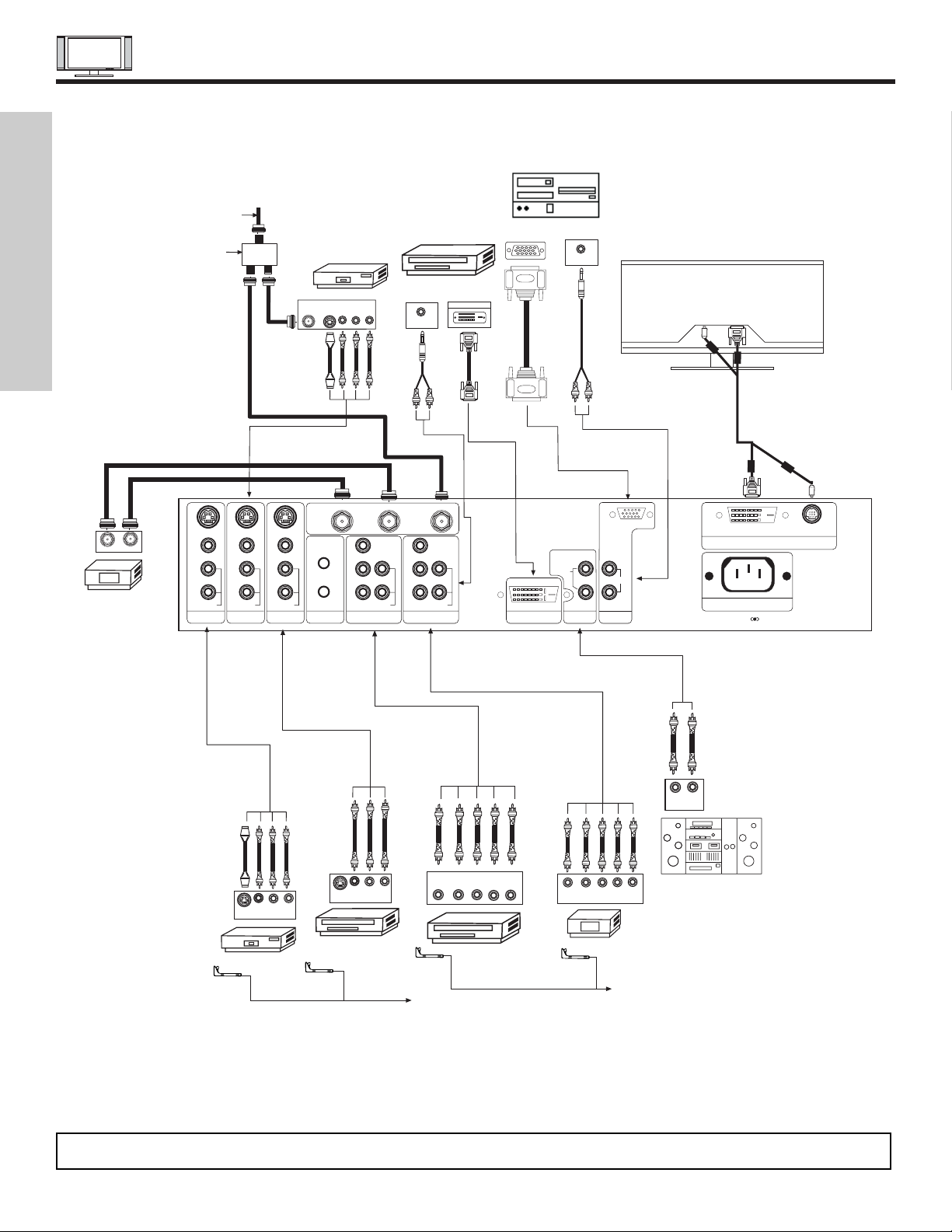
REAR PANEL CONNECTIONS
22
Rear Panel of Display Monitor
VCR #1
Outside antenna or
cable TV coaxial cable
2-Way signal splitter
ANT
IN
OUTPUT
S-VIDEO
VLR
Stereo System Amplifier
LR
INPUT
Laserdisc player, VCR,
camcorder, etc.
OUTPUT
Y P
B
P
R
L R
HDTV Set-Top Box
DVD Player
Cable TV Box
OUTPUT
INPUT
(PROVIDED)
(PROVIDED)
(PROVIDED)
DIGITAL
OUTPUT CAPABILITY
DIGITAL OUTPUT
P
B
P
R
P
B
P
R
Y/VIDEO
R
L/(MONO)
AUDIO
L
R
S-VIDEO
VIDEO
AUDIO
R
S-VIDEO
VIDEO
AUDIO
R
S-VIDEO
VIDEO
MONITOR OUT INPUT 4 INPUT 3 IR BLASTER
L/(MONO)L/(MONO)
AUDIO
Y
R
L/(MONO)
AUDIO
INPUT 2 INPUT 1
ANT B
TO CONVERTER
ANT A
DVI-HDTV
INPUT 1
L
AUDIO
R
AUDIO OUT
ANALOG INPUT
L/(MONO)
R
AUDIO
RGB
TruBass SRS and symbol are trademarks of SRS Labs, Inc.
AC IN
TO MONITOR
Please use HITACHI specified cable.
OUTPUT
YP
B/CBPR/CR
L R
VCR #2
V L R
OUTPUT
S-VIDEO
V L R
INPUT
S-VIDEO
CONNECT TO
IR BLASTER
CONNECT TO
IR BLASTER
AUDIO OUT
RGB
OUTPUT
AUDIO OUT
12345
678910
1112131415
NOTE: Cables are optional, except when specified.
FIRST TIME USE

TIPS ON REAR PANEL CONNECTIONS
23
FIRST TIME USE
• S-VIDEO connections are provided for high performance laserdisc players, VCRs etc. that have this feature. Use these
connections in place of the standard video connection if your device has this feature.
• If your device has only one audio output (mono sound), connect it to the left audio jack on the AVC Center.
• Refer to the operating guide of your other electronic equipment for additional information on connecting your hook-up cables.
•Asingle VCR can be used for VCR #1 and VCR #2, but note that a VCR cannot record its own video or line output (INPUT: 4 in
the example on page 22). Refer to your VCR operating guide for more information on line input-output connections.
• Connect only 1 component (VCR, DVD player, camcorder, etc.) to each input jack.
• COMPONENT: Y-PBPR (Input 1 & 2) connections are provided for high performance components, such as DVD players and settop-boxes. Use these connections in place of the standard video connection if your device has this feature.
•Your component outputs may be labeled Y, B-Y, and R-Y. In this case, connect the components B-Y output to the TV’s PBinput
and the components R-Y output to the TV’s PRinput.
•Your component outputs may be labeled Y-CBCR. In this case, connect the components CBoutput to the TV’s PBinput and the
components CRoutput to the TV’s PRinput.
• It may be necessary to adjust TINT to obtain optimum picture quality when using the Y-PBPRinputs. (See page 45)
•To ensure no copyright infringement, the MONITOR OUT output will be abnormal, when using the
Y-PBP
R
, RGB and DVI-HDTV input
jacks.
• Input 1 can accept component
Y-PBPRsignal and DVI signal (No composite signal).
• Input 2 can accept both component Y-PBPRand composite video signal.
•You may use VIDEO or S-VIDEO inputs to connect to INPUT 3, 4 or 5, but only one of these, VIDEO or S-VIDEO, may be used
at a time for each input. S-VIDEO has priority over VIDEO.
• S-VIDEO monitor output may be used for recording only when the input is of S-VIDEO type.
• When using a DVI input from a Set-Top-Box, it is recommended to use a 1080i or 720p input signal.
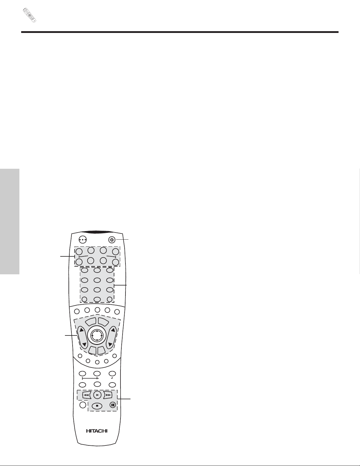
REMOTE
P
OW
ER
T
V
VC
R
C
BL
DVD
1
2
4
5
6
3
7
89
0
INFOSL
E
EP
A
/
V NET
EXIT
ME
NU
C
H
VO
L
M
UTE
PIP PI
P
CH
SW
AP
FREEZE
P
I
P M
ODE
PIP ACCESS
VIDEO
SOU
R
CE WIZ
AR
D
REC
SEL
E
CT
TV/
RGB
ASPECT
S
TB
AN
T
L
A
S
T
C
H
V
C
R
P
L
U
S
+
S
V
C
S
G
U
I
D
E
/
T
V
S
C
H
D
V
I
D
1
V
I
D
2
V
I
D
3
V
I
D
4
V
I
D
5
TAPE
CD
A
MP
M
OD
E
C
LU-57
2
3TS
I
24
In addition to controlling all the functions on your HITACHI Plasma TV, the new remote control is designed to operate different
types of VCRs, CATV (Cable TV) converters, set-top-box, satellite receiver, DVD players, and other audio/video equipment with
one touch. Basic operation keys are grouped together in one area.
To operate your Plasma TV, point the remote control at the remote sensor of the AVC box/Display Monitor and press the TV button. The TV button will blink, indicating that the remote will now control your television.
To operate your VCR, point the remote at the remote sensor of the VCR and press the VCR button. The VCR button will blink,
indicating that the remote will now control your VCR (see page 35 for instructions on how to program the remote to control your
VCR).
To operate your cable box, point the remote at the remote sensor of the cable box and press the CABLE (CBL) button. The CBL
button will blink, indicating that the remote will now control your cable box (see page 36 for instructions on how to program the
remote to control your cable box).
To operate your set-top-box or satellite receiver point the remote at the remote sensor of the set-top-box and press the SET-TOPBOX (STB) button. The STB button will blink, indicating that the remote will now control your set-top-box. If you have a satellite
receiver, use this button to program your satellite receiver (see page 37 for instructions on how to program the remote to control your set-top-box).
To operate your DVD player, point the remote at the remote sensor of the DVD player and press the DVD button. The DVD button will blink, indicating that the remote will now control your DVD player (see page 38 for instructions on how to program the
remote to control your DVD player).
To operate additional audio equipment, point the remote at the remote sensor of the component you wish to control and press
the CD, PVR or AMP button. This button will blink, indicating that the remote will now control the desired component (see page
39 for instructions on how to program the remote to control additional Audio equipment).
These buttons allow the remote to control your TV, VCR,
cable box, satellite receiver, DVD player, or other
Audio equipment depending on which mode is
chosen, as explained above.
, LIGHT BUTTON
When you are in a dark room, press the light button
on the remote to light up the buttons shown in and the
source button will blink. The light will stay on for about 8
seconds if the light button is not pressed again. These
buttons will not appear to illuminate if the room is too
bright.
POWER
TV
VCR
CBL
DVD
1
2
4
56
3
7
89
0
INFOSLEEP
A/V NET
EXIT
MENU
CHVOL
MUTE
PIP SURF
SWAP
FREEZE
PIP MODE
PIP ACCESS
DAY/NIGHT
SOURCE WIZARD
REC
SELECT
TV/RGB
ASPECT
STB
ANT
LAST CH
VID 1
VID 2
VID 3
VID 4
V
ID
5
PVR
CD
AMP
VIDEO
THE REMOTE CONTROL
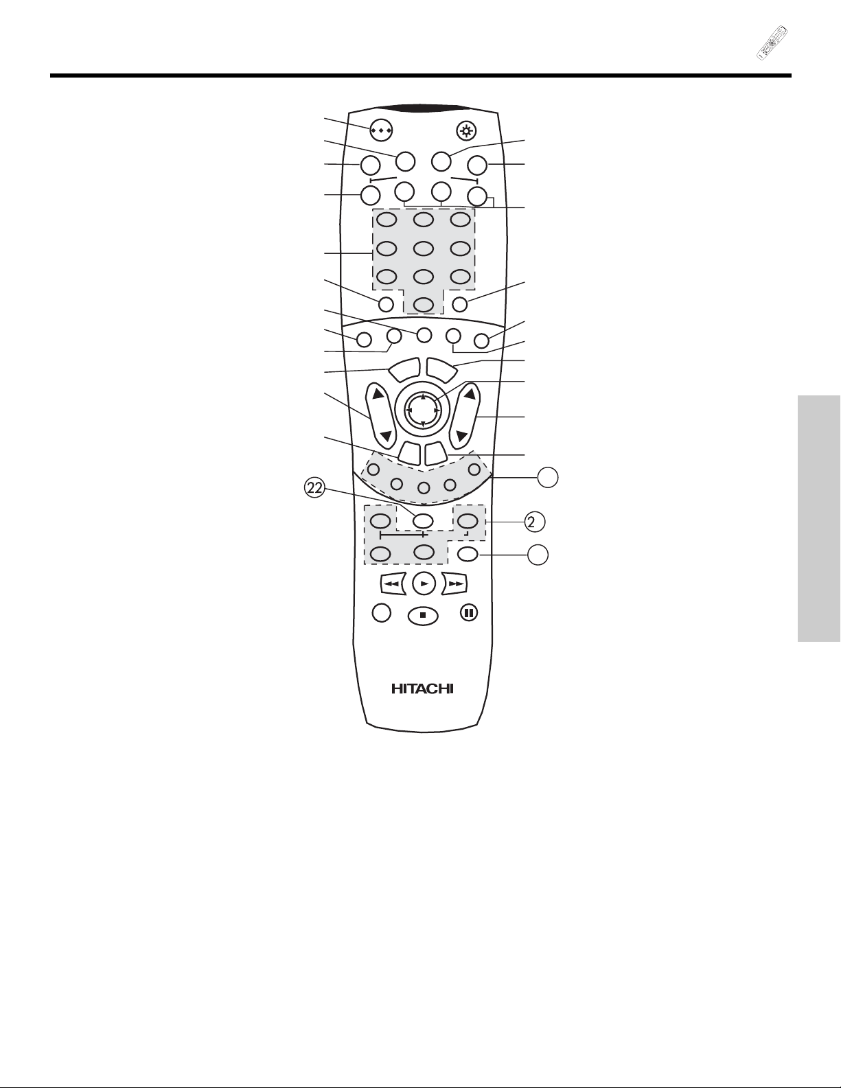
PO
W
ER
T
V
VCR
CBL
DVD
1
2
4
5
6
3
7
89
0
I
NFOSL
E
EP
A/V NET
EXIT
M
E
N
U
CHVOL
M
UTE
PIP PIP CH
SW
A
P
FREEZE
PIP M
ODE
PI
P
A
CCESS
VIDEO
S
OURC
E
W
IZAR
D
R
EC
SE
L
E
C
T
T
V
/RGB
ASP
E
CT
S
TB
A
N
T
L
A
S
T
C
H
V
C
R
P
L
U
S
+
S
V
C
S
G
U
I
D
E
/
T
V
S
C
H
D
V
I
D
1
V
ID
2
VID 3
V
I
D
4
V
I
D
5
T
A
PE
CD
AMP
M
ODE
CLU-5723
TSI
25
HOW TO USE THE REMOTE TO
CONTROL YOUR PLASMA TV
POWER button
Press this button to turn the Plasma TV on or off when the remote is in TV mode (see page 24 for instructions on how to set the
remote control to TV mode).
TV button
When the TV button is pressed, it will blink, to indicate the remote is in TV mode.
VCR button
When the VCR button is pressed, it will blink to indicate the remote is in VCR mode (see page 35).
CABLE (CBL)
When the CABLE button is pressed, it will blink to indicate the remote is in CABLE mode (see page 36).
SET-TOP-BOX (STB)
When the STB button is pressed, it will blink to indicate the remote is in STB mode (see page 37).
If you have a Satellite receiver, use this button to program your Satellite receiver (see page 37).
DVD button
When the DVD button is pressed, it will blink to indicate the remote is in DVD mode (see page 38).
1
23
24
POWER
TV
VCR
CBL
DVD
1
2
4
56
3
7
89
0
INFOSLEEP
A/V NET
EXIT
MENU
CHVOL
MUTE
PIP SURF
SWAP
FREEZE
PIP MODE
PIP ACCESS
DAY/NIGHT
SOURCE WIZARD
REC
SELECT
TV/RGB
ASPECT
STB
ANT
LAST CH
VID 1
V
ID
2
VID 3
VID 4
VID 5
PVR
CD
AMP
VIDEO
THE REMOTE CONTROL
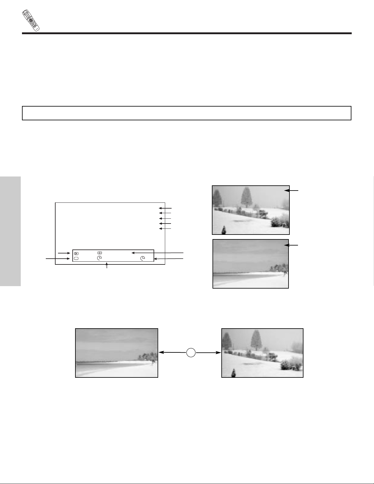
P
O
W
E
R
T
V
V
C
R
CBL
DVD
1
2
4
5
6
3
7
8
9
0
I
N
F
O
S
L
EE
P
A/V
NET
E
XIT
MENU
CHVOL
MU
T
E
PI
P
PIP C
H
S
W
AP
F
RE
EZ
E
P
I
P
MO
D
E
PIP
A
C
CE
SS
V
I
D
E
O
S
OUR
C
E
W
IZ
A
RD
RE
C
SE
L
E
C
T
T
V/RG
B
A
S
P
EC
T
S
TB
ANT
L
A
S
T
C
H
V
C
R
PL
U
S
+
S
V
C
S
G
U
I
D
E
/
T
V
S
C
H
D
V
I
D
1
V
I
D
2
V
I
D
3
V
I
D
4
V
ID
5
T
A
P
E
C
D
A
MP
M
ODE
CLU-
57
23TSI
26
HOW TO USE THE REMOTE
TO CONTROL YOUR PLASMA TV
THE REMOTE CONTROL
CD, PVR, AMP buttons
When pressed, each of these buttons will blink to indicate the remote is in Audio mode (see page 39).
CHANNEL selector buttons
CHANNEL selector buttons are used to select channels, lock access code, etc.
Enter one, two, or three numbers to select channels. Enter “0” first for channels 1 to 9, or simply press the single digit channel you
wish to tune then wait a few seconds for the TV to tune. For channels 100 and above, press the “1” button, wait until two dashes
appear next to the channel display on your TV, then enter the remaining two numbers using the number buttons.
Channel selection may also be performed by pressing CH up () or down ().
SLEEP button
Press this button to display the sleep timer in the lower center of the screen. Every subsequent press of this button will add 15 minutes to this timer, up to a maximum of three hours. Once set, use INFO when you want to view time remaining. If the SLEEP button is pressed while the timer is set, it will reset to the original condition.
INFO button
Press this button when you want to check the channel being received, the picture source, if the channel has stereo (ST) or second
audio program (SAP), the time, CHANNEL ID and if the SLEEP timer is set.
ANTENNA button
The ANT button will select between Antenna A and Antenna B each time the button is pressed.
NOTE: The Plasma TV may not receive some channels if you are not in the correct ANTENNA/CABLE mode (see page 50).
ANT
TV/RGB button
Press this button to toggle between RGB (Analog) mode and TV mode.
When an S-VIDEO
Input is connected to
VIDEO: 3.
When a COMPONENT
VIDEO: Y-PBPRInput
is connected to
VIDEO: 1.
3:32 PM
S-IN:3
VID 3
Main Picture Source
Time
Wide
Mode
Day/Night
Mode
Closed
Captioning
Off Timer
Sleep Timer
3:32 PM
Ant A 22
Stereo
R
1080i Format
Day 4:3 Expanded
Off 0:00 AM -:--
View
Zzzz
CC
Audio Broadcast
Broadcast Rating
Signal Format
3:32 PM
YPBPR:1
VID 1
3:32 PM
Ant B 22
Stereo
R
3:32 PM
Ant A 15
Stereo
G
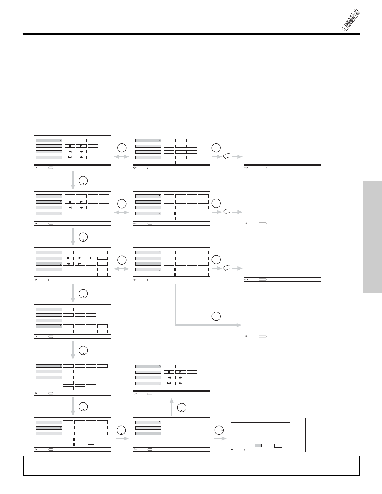
P
OWER
T
V
V
CR
C
BL
DVD
1
2
4
56
3
7
8
9
0
I
N
FO
SLEEP
A/V
N
ET
EXI
T
MEN
U
C
H
VOL
MU
TE
PIP PIP CH
S
WAP
FREEZE
PIP MODE
PIP A
C
C
ESS
VI
DEO
SOU
R
CE
WIZA
R
D
RE
C
SELECT
TV
/
RGB
ASP
ECT
STB
ANT
L
AS
T C
H
V
CR
PL
US
+
S
V
C
S
G
U
I
D
E
/
T
V
SCHD
V
I
D
1
VI
D 2
V
I
D
3
V
I
D
4
V
ID 5
TA
P
E
CD
AMP
MO
D
E
CLU-
5
723TS
I
27
HOW TO USE THE REMOTE
TO CONTROL YOUR PLASMA TV
THE REMOTE CONTROL
AV NET button
Press this button to access the Audio/Video network (AV Net) menu. The AV Net allows the user to control external components
with the Plasma TV’s remote control. When you press the AV NET button, the following window will pop up within the Display
Monitor screen. The window will disappear after 30 seconds if you don’t press any buttons.
The AV Net Setup Wizard will automatically start upon the very first use. (see page 19-21).
THUMBSTICK or to highlight the equipment you wish to control or setup and then press THUMBSTICK .
Use THUMBSTICK , , , to navigate and SELECT to select button. The command on the button is passed through the IR
mouse and onto the AUDIO/VIDEO equipment. These on-screen buttons are called “Soft Keys”.
Customize your Audio/Video equipment list and soft keys by selecting the “Custom” icon and following the instructions of the AV
NET learning wizard (see page 28).
This window shows the available Audio/Video equipment soft keys. The equipment list will scroll up or down.
AV Receiver
PV Recorder
VCR
DVD
Move
POWER MENU MORE
THUMB
STICK
SELECT
THUMB
STICK
INFO
Device Setting
AV Receiver
PV Recorder
VCR
DVD
Move
POWER MENU MORE
SEL
Previous Page
123
456
7
0
98
MORE..
AV Receiver
PV Recorder
VCR
DVD
Move
POWER
INFO
Device Setting
CH CH
MENU
TV/VCR
MORE
AV Receiver
PV Recorder
VCR
DVD
Move
POWER
SEL
Previous Page
CH CH
MENU
TV/VCR
MORE
123
456
7
0
98
THUMB
STICK
SELECT
MORE..
THUMB
STICK
AV Receiver
PV Recorder
VCR
DVD
Move
INFO
Device Setting
POWER
CH CH
INFO
THUMB
STICK
AV Receiver
PV Recorder
VCR
DVD
Move
INFO
Device Setting
THUMB
STICK
Custom
Set Top Box
Cable Box
Move
INFO
Device Setting
POWER
CH CH
INFO
123
456
7
0
98
THUMB
STICK
Custom
Set Top Box
Cable Box
Move
INFO
Device Setting
Custom
Set Top Box
Cable Box
Move
INFO
Device Setting
SETUP
THUMB
STICK
THUMB
STICK
TV/VCR
INFO
GUIDE
MORE
POWER
CH CH
AUDIO
VOL VOL
SOURCE4
SOURCE1
SOURCE2 SOURCE3
SOURCE8
SOURCE5
SOURCE6 SOURCE7
LAST CH
POWER
CH CH
MENU
123
456
7
0
98
LAST CH
INFO
GUIDE
THUMB
STICK
HITACHI AV NET WIZARD (Learning)
Use this wizard to manually learn
or modify your AV NET soft keys.
BACK Learn Modify
AV Receiver
PV Recorder
VCR
DVD
Move
POWER MENU MORE
INFO
Device Setting
Move
SEL
Start Wizard
AV Receiver
PV Recorder
VCR
DVD
Move
POWER
SEL
Select
CH CH
MENU
TV/VCR
INFO
123
456
7
0
98
THUMB
STICK
SELECT
MORE..
GUIDE
MORE
-
LAST CH
MENU
THUMB
STICK
SELECT
MENU
Move
ORIGINAL MENU
OF EQUIPMENT
AV NET
Return
MENU
THUMB
STICK
SELECT
MENU
Move
ORIGINAL MENU
OF EQUIPMENT
AV NET
Return
MENU
THUMB
STICK
SELECT
MENU
Move
ORIGINAL MENU
OF EQUIPMENT
AV NET
Return
THUMB
STICK
SELECT
GUIDE
Move
ORIGINAL GUIDE
OF EQUIPMENT
AV NET
Return
NOTE: After selecting the “MENU” soft key, press the MENU button of the Plasma TV remote control to access the Menu of a
specific equipment.
 Loading...