

Hitachi 43FDX01B, 53FDX01B Schematic

SAFETY PRECAUTIONS......................................................................................................2
TECHNICAL CAUTIONS ......................................................................................................3
SPECIFICATIONS ................................................................................................................4
GENERAL INFORMATION....................................................................................................5
CUSTOMIZED PICTURE AND SOUND ADJUSTMENTS ....................................................6
SERVICE ADJUSTMENTS..................................................................................................1 1
DC VOLTAGE......................................................................................................................21
WAVEFORMS......................................................................................................................32
BASIC CIRCUITDIAGRAM................................................................................................35
PRINTED CIRCUITBOARDS............................................................................................48
BLOCK DIAGRAM..............................................................................................................49
WIRING DIAGRAM..............................................................................................................50
CHASSIS WIRING DRAWING............................................................................................51
EXPLODED VIEW..............................................................................................................57
REPLACEMENTPARTS LIST............................................................................................59
EXPLODED VIEW PARTS LIST..........................................................................................86
QUICK REFERENCE PARTS LIST....................................................................................87
PA
No. 0132
NTSC
DP05/DP05F Chassis
R/C: CLU-572TSI
R/C: CLU-575TSI
SPECIFICATIONS AND PARTS ARE SUBJECT TO CHANGE FOR IMPROVEMENT
AUGUST 2000 HHEA-MANUFACTURING DIVISION
43FDX01B
53FDX01B
SERVICE MANUAL
This addendum gives differences between DP05/DP05F and the DP06 chassis models. For any
other information, see the 53SDX01B or 61SDX01B Service Manual PANo. 0131 issued in JUNE 2000.
CAUTION: Before servicing this chassis, it is important that the service technician read the
”Safety Precautions” and “Servicing Precautions” in Service Manual PA No. 0131.
PROJECTION COLOR TELEVISION

11
SERVICE ADJUSTMENTS
1. ASSEMBLED P.W.B ADJUSTMENT..................................................................................................................12
1-1. Memory Initialization (NTSC, SDTV and HDTV) ....................................................................................12
1-2. Comb Filter Operation Check ................................................................................................................15
1-3. Audio Operation Check ..........................................................................................................................15
1-3-1. Tone Control Operation Check ....................................................................................................15
1-3-2. Perfect Volume Operation Check ................................................................................................15
1-3-3. SRS Surround Operation Check ..................................................................................................15
2. FINAL ASSEMBLY ADJUSTMENT ..................................................................................................................16
2-1. Raster Position........................................................................................................................................16
2-2. Vertical Size (Progressive mode)............................................................................................................16
2-3. Horizontal Size (Progressive and HD mode) ..........................................................................................16
2-4. Convergence Adjust (Progressive and HD mode)..................................................................................17
*IMPORTANT
For many of the above adjustments, it is necessary to have an HDTV (1080i) signal generator, SDTV (480P) signal generator, as well as the usual NTSC (480i) signal generator.
Hitachi recognizes that few companies offer HDTV or SDTV signal generators and that the cost of these generators is sometimes prohibitive. For this reason, we suggest the use of a set-top-box for HDTV and SDTV adjustments. Usually, there is a switch on the set-top-box which enables it to output HDTV (1080i) or SDTV (480P) signals even with no input. In this case, the sync is automatically detected by the TV (at the Y-P
BPR
Inputs on the
rear panel).
12
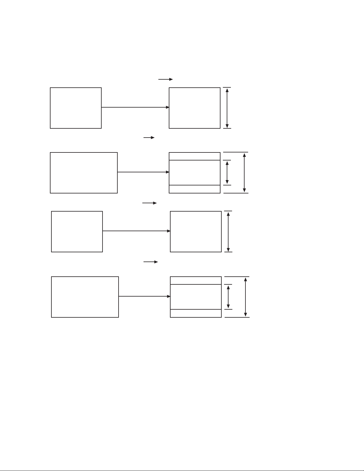
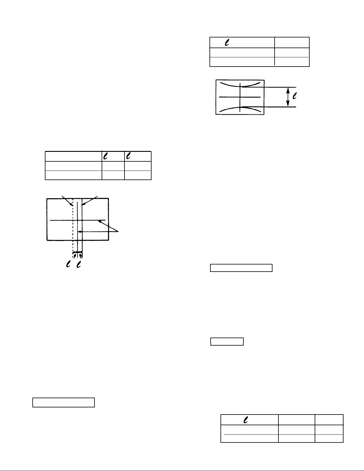
DISPLAY FORMAT OF COMPONENT VIDEO TERMINAL (YCBCR/YPBPR).
SDTV SIGNAL FORMAT: SMPTE-170M
HDTV SIGNAL FORMAT: ITU-R709, SMPTE-274M
A. NORMAL MODE
(1) NTSC/SDTV: 480i 4X3 (15.75kHz) 480P 4x3 (31.5kHz)
4x3
480i
15.75kHz
4x3
480P
31.5kHz
(2) SDTV: 480i 16x9 (15.75kHz) 480P 4x3 (31.5kHz)
16x9
480i
15.75kHz
4x3
480P
31.5kHz
Insertion panel to top and bottom.
360
Lines
480
Lines
(3) SDTV: 480P 4X3 (31.5kHz) 480P 4x3 (31.5kHz)
4x3
480P
31.5kHz
4x3
480P
31.5kHz
480
Lines
480
Lines
(4) SDTV: 480P 16x9 (31.5kHz) 480P 4x3 (31.5kHz)
16x9
480P
31.5kHz
4x3
480P
31.5kHz
Insertion panel to top and bottom.
360
Lines
480
Lines
1. ASSEMBLED P.W.B. ADJUSTMENT
1.1 MEMORY INITIALIZATION
13
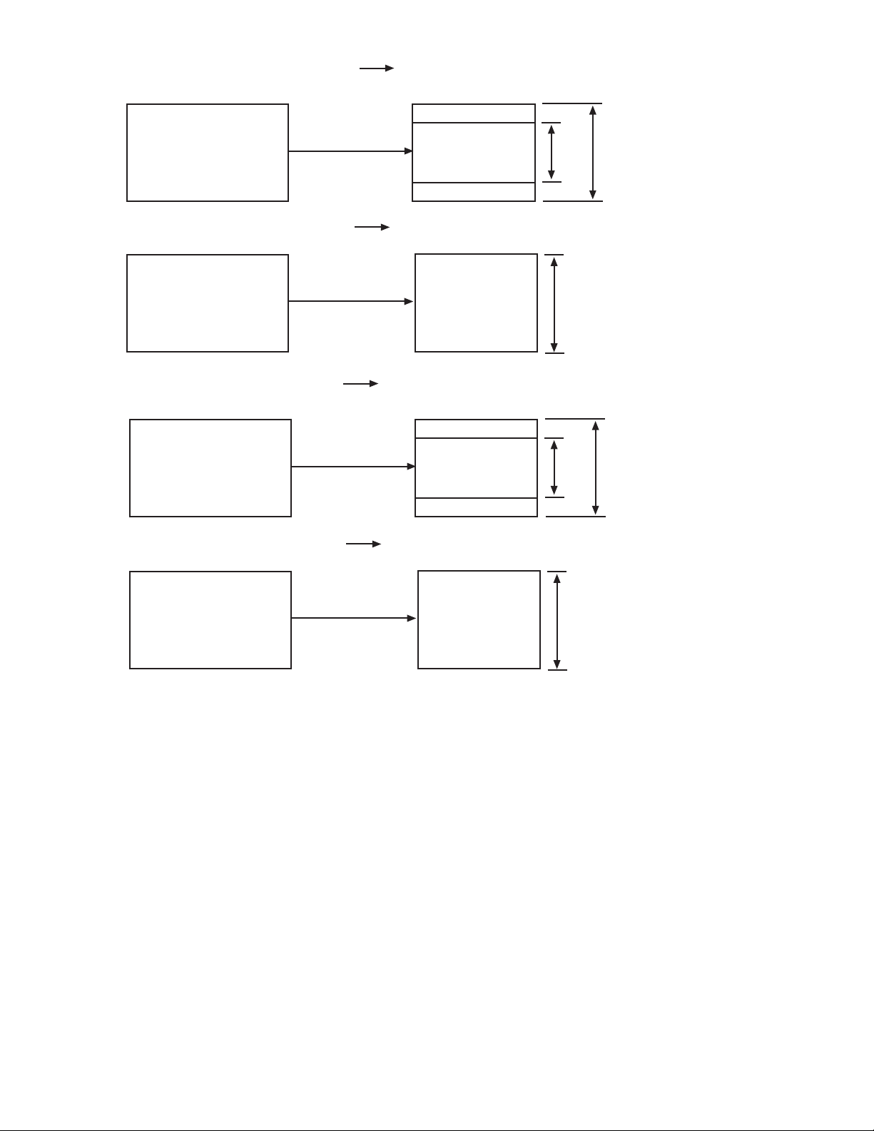
(5) HDTV: 1080i 16x9 (33.75kHz) 1080i 4x3 (33.75kHz)
16x9
1080i
33.75kHz
16x9
1080i
33.75kHz
Insertion panel to top and bottom.
810
Lines
1080
Lines
4x3
1080i
33.75kHz
1080
Lines
(6) HDTV: 1080i 16x9 (33.75kHz) 1080i 4x3 (33.75kHz)
16x9
1080i
33.75kHz
(7) HDTV: 720P 16x9 (45kHz) 480P 4x3 (31.5kHz)
16x9
720P
45kHz
16x9
480P
31.5kHz
Insertion panel to top and bottom.
360
Lines
480
Lines
4x3
480P
33.75kHz
480
Lines
(8) HDTV: 720P 16x9 (45kHz) 480P 4x3 (31.5kHz)
16x9
720P
45kHz
14
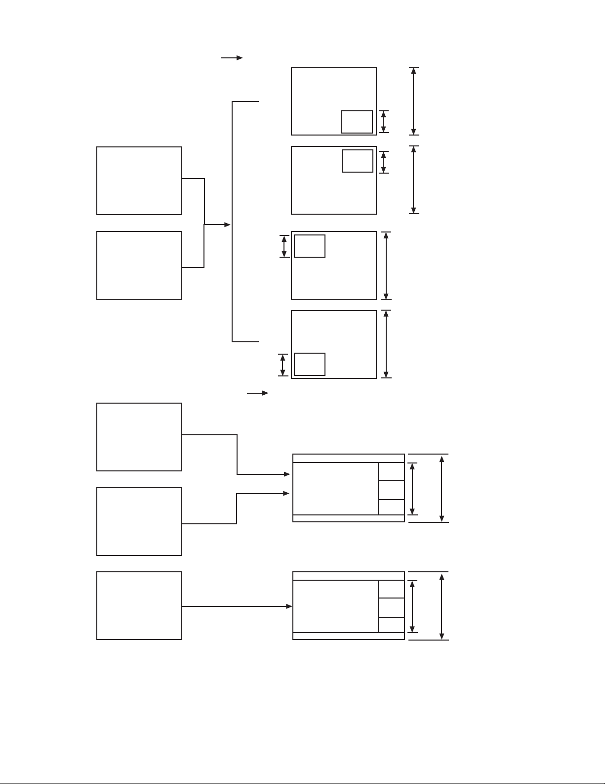
C. SURF/STROBE MODE NTSC 480P 4x3 (31.5kHz)
Main
Picture
480
Lines
360
Lines
SUB
SUB
SUB
Main
Picture
Sub
Picture
NTSC
Picture
Moving
Picture
480
Lines
360
Lines
STROBE
STROBE
STROBE
B. SINGLE MODE NTSC only 480P 4x3 (31.5kHz)
Main Picture
NTSC Only
Sub Picture
NTSC Only
Main
Picture
NTSC
Main
Picture
NTSC
Main
Picture
NTSC
Main
Picture
NTSC
Sub
NTSC
Sub
NTSC
Sub
NTSC
Sub
NTSC
480
Lines
160
Lines
160
Lines
480
Lines
160
Lines
160
Lines
480
Lines
480
Lines
15
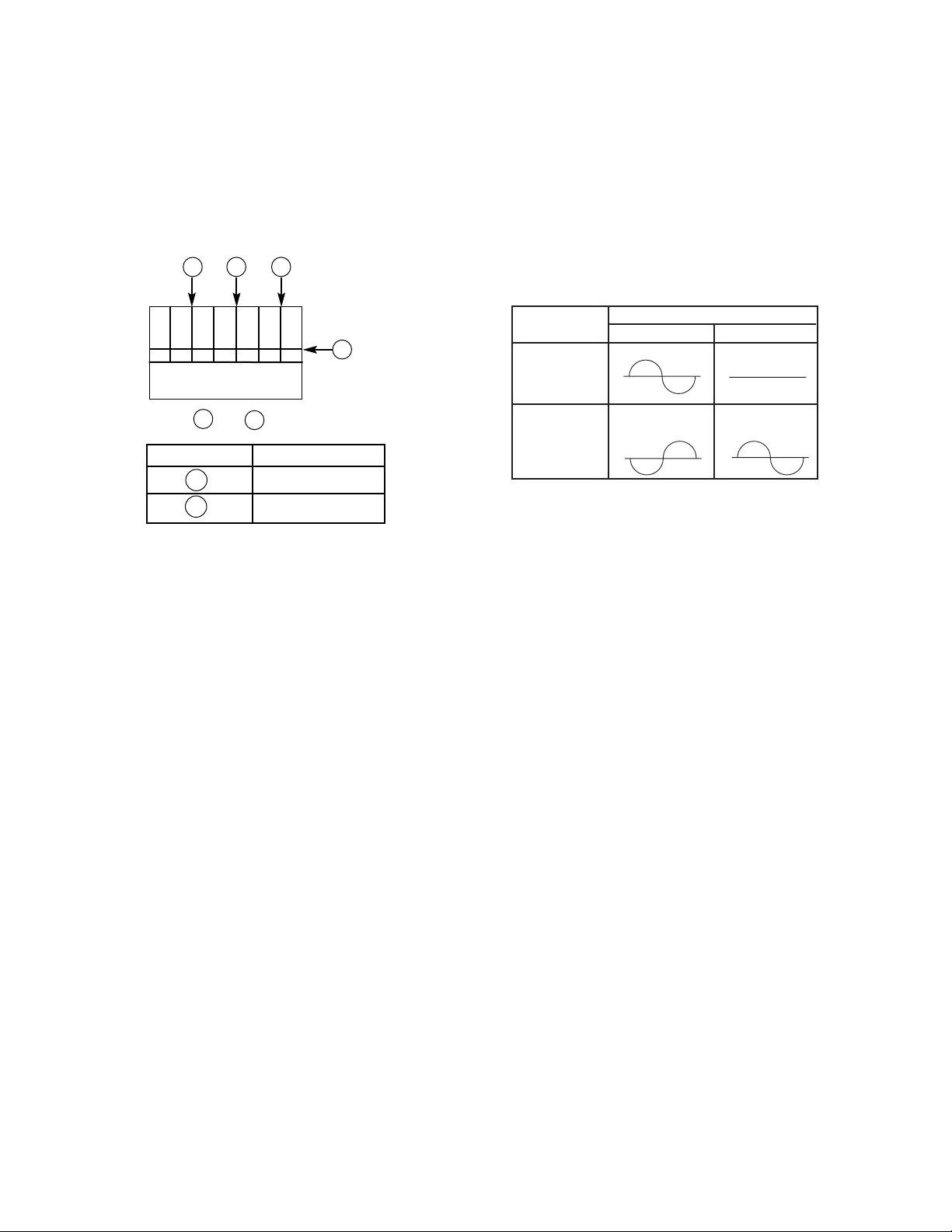
1.2 Comb filter operation check
Adjustment preparation
(1) Receive the color bar signal at the regular tun-
ing point.
(2) Set the CONTRAST control to MAX and the
other controls to center.
(3) Set the A.I. to OFF.
Adjustment procedure
(1) Check that between the color bars there are not
line dots every second color bar as shown in the
drawing.
A
A A
B
43/53FDX01B
A No Dots
B No Dots
Check and line dots.
B
A
1.3 AUDIO OPERATION CHECK
1.3.1 TONE CONTROL CHECK
Preparation for adjustment
(1) Input an audio signal of 250Hz and 3Khz in
order with level of 150mVrms to the L/mono
audio input.
(2) Set the Volume to around the center.
(3) Set SRS SURROUND to OFF.
(4) Set LOUDNESS to OFF.
(5) Set INTERNAL SPEAKER to ON.
Adjustment Procedure
(1) Select BASS mode and check that the audio
output level of the speakers changes to
emphasized or supporessed when adjust to
max. or min. of the adjustment mode.
(2) Select TREBLE mode and check that the
audio output level of the speakers changes
by emphasized or suppressed when adjust to
max. or min. of the adjustment mode.
(3) Select BALANCE mode and check that the
audio output changes right or left when adjust
to right or left of the adjustment mode.
1.3.3 SRS CHECK
Preparation for adjustment
(1) Set the Master Volume to around the center.
(2) Set the BALANCE to the center.
(3) Set the BASS and TREBLE to the center.
(4) Set the LOUDNESS to OFF.
(5) Set PERFECT VOLUME to OFF.
(6) Set INTERNAL SPEAKER to ON.
(7) Input the audio signal of 400Hz in order with
level of 1Vpp to the R audio inpu and no signal
to the L audio input.
Adjustment Procedure
(1) Check the following wave form at the HiFi out.
1.3.2 PERFECT VOLUME OPERATION CHECK
Preparation for adjustment
(1) Set PERFECT VOLUME to ON.
(2) Set the Volume to around the center.
(3) Set INTERNAL SPEAKER to on.
Procedure
(1) Input 100mVrms, 200mVrms, 300mVrms and
400mVrms of 1KHz sound signal to L/MONO
terminal.
(2) Check same level sound is output from SP
when 200mVrms, 300mVrms and 400mVrms
of 1KHz sound signal is input.
OUTPUT SRS
ON OFF
HiFi L out 1.4±0.05Vpp No signal
HiFi R out 1.9±0.05Vpp 0.7±0.05Vpp
16
Notes: (1) Only adjust the vertical size for
progressive mode (NTSC).
Because both modes (NTSC and
HD) have the same vertical freuency.
(2) If internal cross-hatch does not
appear after clearing RAM data,
press service switch again (on
POWER/DEFLECTION PWB).
(3) To restore old RAM data, turn TV
off and on.
=
PROGRESSIVE
MODE
43FDX01B 550
53FDX01B 670
Tolerance: 앐 5mm
2.2 Vertical size adjustment
Adjustment preparation
(1) The set can face east or west.
(2) Set video conditions to factory preset.
(3) The electric focus and horizontal position adjust-
ment should have been coarse adjusted.
(4) Start adjustment after TV is turned on for 20
minutes or more.
Adjustment procedure
(1) Receive any NTSC signal.
(2) Press and hold the SERVICE ONLY SW on
DEFLECTION PWB to display DCU crosshatch
with convergence data cleared.
(3) Adjust V. SIZE as following by using R630.
(4) After adjustment, press SERVICE ONLY switch
to exit from DCU crosshatch.
PROGRESSIVE MODE
1
2
2.3 Horizontal size adjustment
Adjustment preparation
(1) The set can face east or west.
(2) Set video conditions to factory preset.
(3) BEAM FORM adjustment should be finished.
(4) Convergence should not be corrected.
(5) Start adjustment after TV is turned on for 20
minutes or more.
Adjustment procedure
(1) Receive any NTSC signal.
(2) Press and hold the SERVICE ONLY SW on
DEFLECTION PWB to display DCU cross-hatch
with Convergence data cleared.
(3) Convergence should not be adjusted.
(4) Adjust H. SIZE by using R683.
(5) After adjustment, press SERVICE ONLY SW to
exit from DCU cross-hatch.
(1) Input 1080I (fH=33. 75kHz) component signal to
VIDEO 2.
(2) Press and hold the SERVICE ONLY SW on
DEFLECTION PWB to display DCU cross-hatch
with convergence data cleared.
(3) Adjust H. SIZE using R686.
(4) After adjustment, press SERVICE ONLY SW to
exit from DCU crosshatch.
H. SIZE SPECIFICATION
PROGRESSIVE MODE
HD MODE
=
PROGRESSIVE
MODE
HD
MODE
43FDX01B 860 860
53FDX01B 1050 1050
Tolerance: 앐 5mm
Geometric
center of the
screen
R
B
(2) Upon completion of adjustment, fix beam center-
ing magnets with white paint.
NOTES: (1) If internal cross-hatch does not appear
after clearing RAM data, press service
switch again.
(2) To restore old RAM data, turn TV off and
on.
12
2.1 Raster position adjustment
Adjustment preparation
(1) The set can face east or west.
(2) Receive the DCU cross-hatch signal.
(3) Set video conditions to factory preset.
(4) Static Focus adjustment should be finished.
(5) The digital convergence RAM should be cleared
(uncorrected state). With the TV set off, press
and hold the service switch located on the
Power/Deflection PWB and then press the
power button.
(6) Start adjustment 20 minutes or more after TV is
turned on.
Adjustment procedure
(1) Turn the centering magnets for red, green, and
blue to satisfy the condition below. The red and
blue horizontal lines should match with green.
V. SIZE SPECIFICATION
2. FINAL ASSEMBLY ADJUSTMENT
(RED) (BLUE)
43FDX01B 20 35
53FDX01B 15 25
Tolerance: 앐 2mm
17
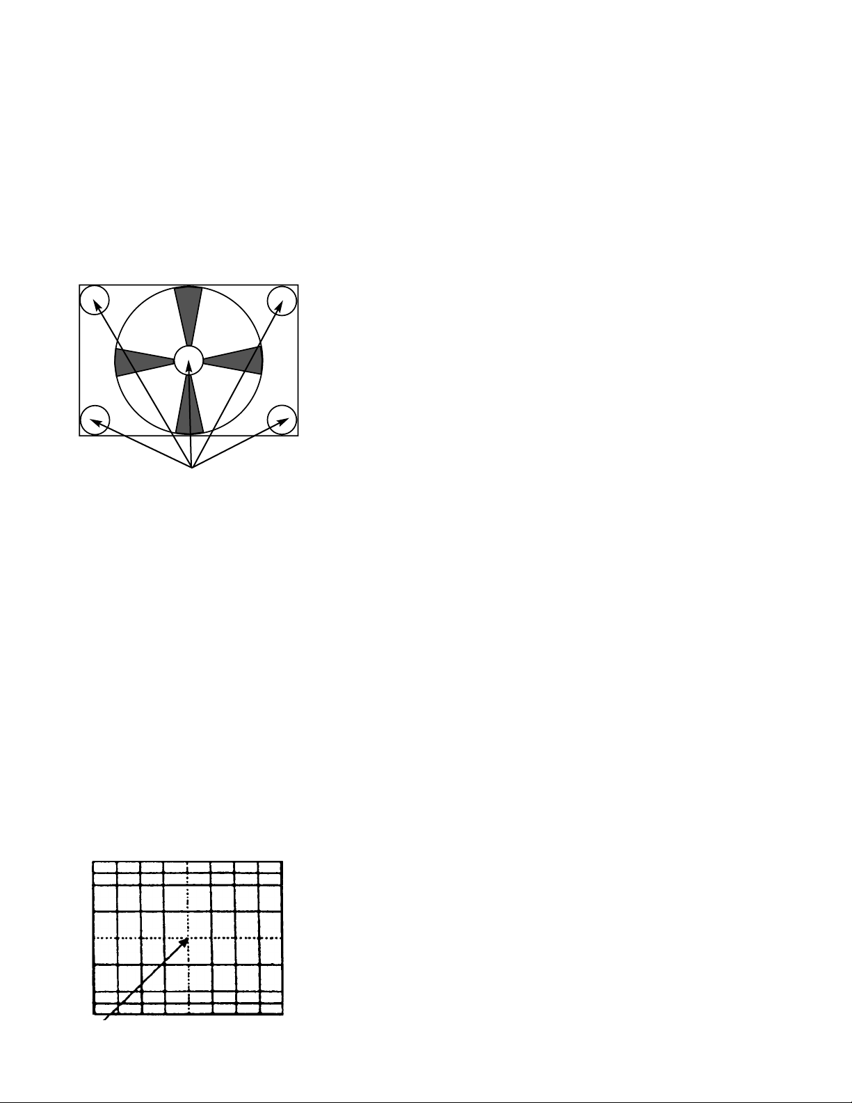
2.12 Digital convergence adjustment
Adjustment preparation
(1) Receive an RF or video signal.
(2) Set controls to factory preset.
(3) Install jig screen on the set.
(4) Note the center of the video pattern displayed.
This is necessary to match dotted lines
(adjustment point viewed) and actual point that
is adjusted and displayed by the video signal.
(5) Press the service only switch (on
POWER/DEFLECTION PWB). The pattern
displayed is now the digital convergence mode.
(6) When performing a complete digital
convergence adjustment CLEAR DATAin RAM.
(With the TV set off, press and hold the service
switch located on the Power/Deflection P.W.B.
and then press the POWER button).
Adjustment Point
S/N($,*&+, )612&/(6&
J=K @&/ -+/ .3(& $,-,#2 012($ -/N($,*&+,A S/N($,
,"& $,-,#2 012($ U@ 1+ ?12($ )-2H JW?<bK $1
,"-, ,"& 2&+,&6 10 2#623& )-,,&6+ #$ ,"& *1$, 23&-6A
7"&2H ,"-, ,"& 012($ /1&$ +1, 9&,
21+$)#2(1($34 516$& -, ,"& &/9&$ 10 ,"& 2#623&
)-,,&6+ $#9+-3 16 261$$I"-,2" $#9+-3A
JLK g6&&+ $,-,#2 012($ -/N($,*&+,A S/N($, ,"& $,-,#2
012($ U@ 1+ ?12($ )-2H JW?<bK J016 96&&+K $1
,"-, ,"& 2&+,&6 10 2#623& )-,,&6+ #$ ,"& *1$, 23&-6A
7"&2H ,"-, ,"& 012($ /1&$ +1, 9&,
21+$)#2(1($34 516$& -, ,"& 2"&2H#+9 )1#+,; ,"&
)&6#)"&64 10 2#623& )-,,&6+ 261$$I"-,2" $#9+-3A
NOTE: Checking point for the periphery of picture.
7"&2H#+9 )1#+,
18
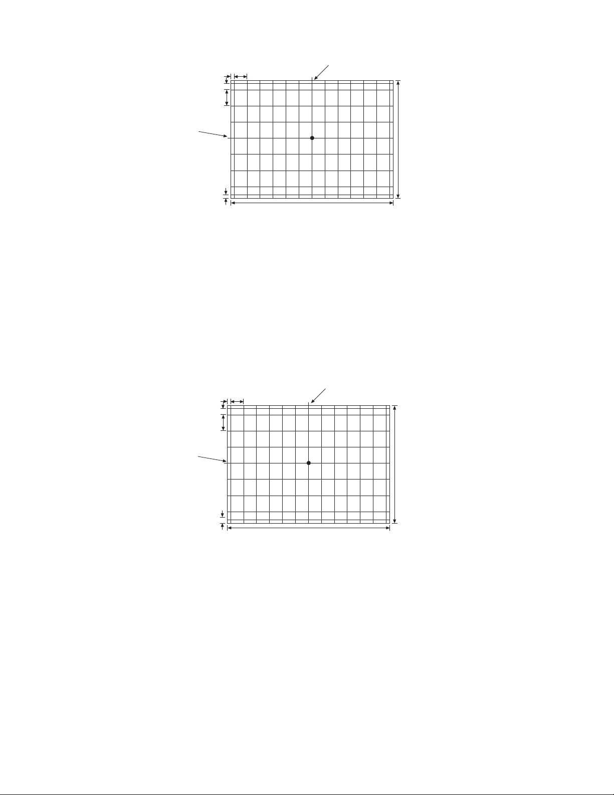
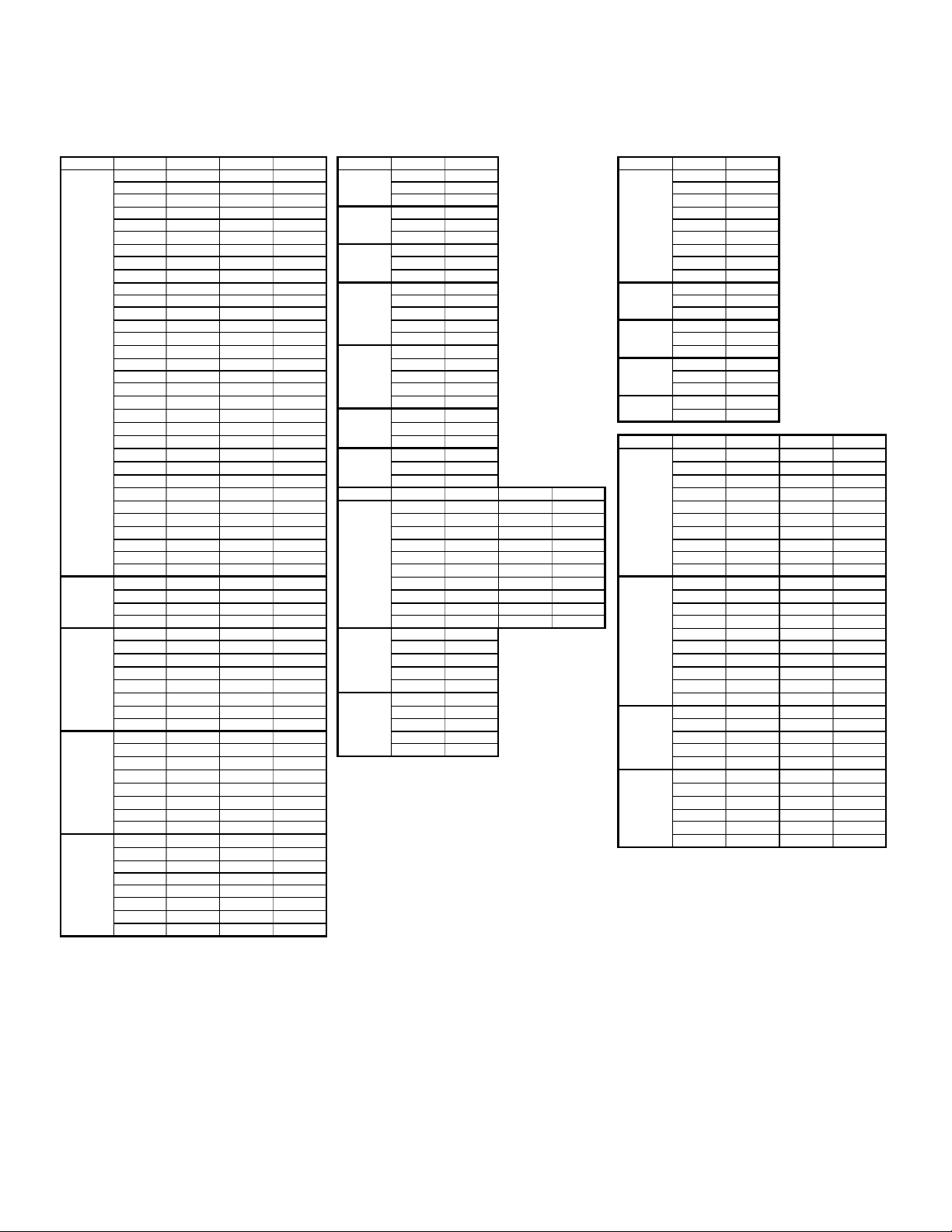
53Ó JIG SCREEN SPECIFICATION 4:3
43Ó JIG SCREEN SPECIFICATION 4:3
(656)
[656]
(874)
[874]
(1.1)
[35.4]
(93.4)
[83.6]
(46.7)
[41.8]
(72)
[72]
(5.0)
[5.0]
MODEL: (Progressive mode)
[HD mode]
UNIT: mm
GEOMETRIC CENTER
OF SCREEN
GEOMETRIC CENTER
OF SCREEN
(808)
[808]
(1078)
[1078]
(1.5)
[43.5]
(115.0)
[103.0]
(57.5)
[51.5]
(88.8)
[88.8]
(6.2)
[6.2]
MODEL: (Progressive mode)
[HD mode]
UNIT: mm
GEOMETRIC CENTER
OF SCREEN
GEOMETRIC CENTER
OF SCREEN

19
Note: If only minor adjustments to convergence are
needed, the jig screen is not necessary. Use
digital data stored in memory and one color as a
reference (red, green, or blue). DO NOT CLEAR
DATAand WRITE to ROM memory.
6#&6#& .HKDFG E"KJDJ"C HOgLKDMFCD
Adjustment preparation
(1) Position adjustment - This will move an entire
color. Use this adjustment to match colors at the
center of the screen. (Active video center from
external signal and physical screen center
should now match from phase adj. 2.2.).
(2) Use the buttons below to switch color to adjust.
“RECALL” - Green
“0” - Red
“INPUT” - Blue
Adjustment procedure
(1) Press the FREEZE button. Extra horizontal lines
appear to confirm raster position mode.
(2) Use the thumb stick to adjust position.
(3) Press FREEZE again to exit raster position
mode.
Notes: (1) Other functions cannot be accessed when
in raster position adjustment mode. Press
FREEZE and confirm extra horizontal lines
disappear to exit raster position mode.
(2) Press MENU to switch between all colors
displayed or adjustment color and Green
only.
6#&6#6 0"CSFGVFCRF E"JCD HOgLKDMFCD
Adjustment preparation
(1) Select color to adjust.
“RECALL” - Green
“0” - Red
“INPUT” - Blue
(2) Use 4, 6, 2, and 5 to move the cursor position
(dotted lines).
(3) Use thumb stick to move the convergence point.
(4) Three adjustment modes are available:
1. (3x3) Press “RECALL” 5 times (only works
when DCU is in uncorrected state)
2. (7x5) Press “0” 5 times
3. (13x9) Press “INPUT” 5 times
For touch-up, only the (13x9) mode is necessary.
This will adjust every cross-hatch intersection point
on the screen.
For complete adjustment, start with (3x3) mode. This
will adjust center point and eight edge points only,
but will greatly reduce adjustment time. Then use
(7x5) mode, and finally (13x9) mode to finish
convergence.
If “S” distortion appears between cross-hatch lines
repeat (7x5) mode to change calculation process
while adjusting to remove distortion, then return to
(13x9) mode to finish touch-up convergence.
Adjustment procedure
(1) Receive any NTSC signal.
(2) Start adjustment at the center of the screen.
(3) Continue adjustment at next closest position.
(4) Adjust center area first, ending with edge
sections.
(5) Press INFO button to perform calculation
operation. This process will take about 2
seconds and no picture will be seen at this time.
(6) After interpolation, check convergence again
and repeat (1)-(5) if necessary.
(7) When convergence is acceptable, press PIP
MODE to write data to ROM memory. ROM
WRITE? is displayed to alarm system that ROM
will be overwritten with new data. Press the PIP
MODE button again to write displayed data to
ROM.
(8) DATA WRITE TO ROM will take approximately 4
seconds and no picture will be displayed.
(9) Green dots will be displayed when operation is
completed.
(10) Press MUTE to return to convergence pattern,
then confirm again convergence is acceptable.
Adjustment procedure
(1) Receive any HD signal.
(2) Repeat steps 2~11 above.
Notes: (1) Display only green for easier adjustment
and match to jig screen. Press “MENU”,
THEN PRESS “RECALL”.
(2) Perform interpolation and data write to ROM
after green adjustment. Once green has
been confirmed to match jig screen, the jig
screen can be removed. Do not readjust the
green color after jig screen has been
removed. This is now your reference color.
(3) Display green and red only and match red to
green.
(4) Display all colors and match blue to green
and red. Touch-up red color if necessary.
(5) Existing DATA in ROM can be read by
pressing the SWAP button 2 times. This
data can be used after replacing a
component (CRT, DY, etc.) Where complete
convergence adjustment is not necessary
be careful not to overwrite this data.
DO NOT write cleared RAM data into ROM
or a complete convergence adjustment will
be necessary.
PROGRESSIVE MODE
HD MODE
21
Symbol Pin No. Vdc Pin No. Vdc Symbol Pin No. Vdc Symbol Pin No. Vdc
1 0.0 33 3.2 1 3.2 1 9.2
2 4.8 34 1.7 I006 2 0.0 2 0.0
3 4.8 35 1.6 3 3.2 3 5.0
4 3.6 36 1.6 1 10.8 4 3.6
5 3.3 37 0.0 I007 2 0. 0 PFS 5 0 . 0
6 1.8 38 0.0 3 9.1 6 0.0
7 3.1 39 0.0 1 7.0 7 3.3
8 1.1 40 0.0 I008 2 0 . 0 8 3.3
9 0.0 41 1.4 3 5.0 9 5.0
10 3.7 42 1.4 1 0.0 1 3.2
11 3.7 43 0.0 2 4.2 PJIG1 2 4.4
12 3 . 3 44 0.3 I009 3 0. 0 3 3.0
13 0.0 45 0.0 4 9.1 1 3.2
14 0.0 46 2.9 5 10.9 PJIG2 2 4.4
15 1.6 47 1.8 1 0.0 3 3.0
I001 16 3.1 48 1.8 2 4 .2 1 3.2
17 0 . 1 49 2.7 I010 3 5. 0 PJIG3 2 3.2
18 0.1 50 2.9 4 5.0 3 0.0
19 3.1 51 0.0 5 7.0 PP1 1 3.0
20 3.0 52 3.2 1 5.3 2 3.0
21 2.9 53 2.8 I011 2 0.0
22 3 .8 54 3.2 3 2.5 Symbol Pin No. Vdc Pin No. Vdc
23 1.5 55 3.2 1 5.3 1 4.8 11 4.5
24 2 . 7 56 0 . 0 I012 2 0 . 0 2 4 . 8 12 0.0
25 3.2 57 3.2 3 3.3 3 4.8 13 0.0
26 2.0 58 3.2 Symbol Pin No. Vdc Pin No. Vdc 4 0.0 14 0.0
27 2.3 59 4 .8 1 5.0 11 5.0 PSU1 5 0.0 15 4.0
28 0.0 60 4.8 2 3.0 12 0.0 6 0.4 1 6 0.0
29 0.0 61 3.2 3 2.9 13 0.0 7 0.0 1 7 5.0
30 1.4 62 1.6 4 2.9 14 4.9 8 3.6 1 8 5.0
31 0 .0 6 3 1 .6 I014 5 1. 6 1 5 2. 4 9 3.6 19 9.2
32 1.4 64 0.0 6 3.0 16 4.6 10 0.0 20 9.2
1 0.0 5 4.8 7 0.0 17 4.7 1 5.0 1 1 0.0
I002 2 0.0 6 0.0 8 0 .1 1 8 4 .7 2 4. 9 1 2 4 .8
3 0.0 7 0.0 9 3.1 19 0.0 3 0.0 1 3 0.0
4 0.0 8 5.0 10 0.0 20 5.0 4 0.0 14 0.0
1 0.2 9 0.0 1 2.7 PSU2 5 2.4 1 5 0.0
2 4.6 10 0.0 2 5.0 6 0.0 16 0.0
3 4.6 11 0.0 I015 3 0 .0 7 4.8 17 0.0
I003 4 4.0 1 2 0. 0 4 3.8 8 0.0 18 0.0
5 4.0 13 0.0 5 5.0 9 0.0 19 30.0
6 4.6 14 4.9 1 2.6 10 0.0 20 29.7
7 0.0 15 4.8 2 5.0 1 33.2 6 0.0
8 0.0 16 5.0 I016 3 0 .0 2 0.0 7 0.0
1 5.0 9 0.0 4 5.0 PQS1 3 10.8 8 0.0
2 5.0 10 0.0 5 5.0 4 10.8 9 0.0
3 0.4 11 0.0 5 10.8 10 4.1
I004 4 4.6 1 2 0. 0 1 7.0 7 5.3
5 4.6 13 0.0 2 7.0 8 5.3
6 0.4 14 4.8 PQS2 3 7.0 9 0.0
7 0.4 15 4.9 4 0.0 10 2.5
8 0.0 16 5.0 5 0.0 11 3.3
1 5.0 9 0.0 6 0. 0 -- --
2 5.0 10 0.0
3 0.0 11 0.0
I005 4 0.0 1 2 2. 5
5 5.3 13 1.6
6 0.0 14 2.5
7 0.0 15 5.0
8 0.0 16 9.1
DC VOLTAGE TABLES
Signal 1 of 3
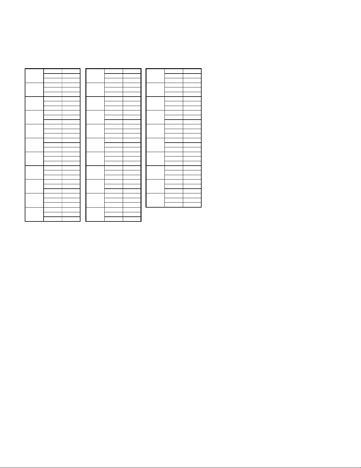
22
DC VOLTAGE TABLES
Signal 1 of 3 Cont.
B 7.6 B 0.0 B 0.7
Q001 C 0.0 Q014 C 3.1 Q030 C 0.0
E 7.6 E 0.1 E 0.0
B 0.7 B 0.6 B 5.3
Q002 C 0.0 Q015 C 0.1 Q031 C 9.1
E 0.0 E 0.0 E 4.6
B 0.7 B 0.2 B 2.5
Q003 C 0.0 Q016 C 3.8 Q034 C 0.0
E 0.0 E 0.0 E 3.2
B 0.0 B 0.1 B 3.2
Q004 C 4.7 Q017 C 2.7 Q035 C 9.1
E 0.0 E 0.0 E 2.6
B 0.0 B 5.9 B 0.0
Q005 C 3.2 Q018 C 0.6 Q036 C 5.0
E 0.0 E 5.9 E 0.0
B-1.7 B 5.3 G 5.0
Q006 C 2.7 Q019 C 0.0 Q037 C 0.0
E 0.0 E 5.9 E 5.0
B 0.0 B 5.3 B 0.0
Q007 C 0.0 Q021 C 9.1 Q038 C 5.0
E 0.7 E 4.6 E 0.0
B 0.4 B 0.0 B 5.0
Q008 C 2.4 Q022 C 10.8 Q039 C 0.0
E 0.1 E 0.0 E 5.0
B 0.5 B 10.8 B 0.7
Q009 C 1.5 Q023 C 0.0 Q040 C 0.0
E 0.1 E 10.8 E 0.0
B 3.2 B 0.0 B 5.0
Q010 C 0.0 Q024 C 10.8 Q046 C 5.0
E 3.2 E 0.0 E 4.4
B 0.1 B 1.4
Q013 C 5.0 Q029 C 5.0
E 0.0 E 3.3
 Loading...