

Page 1
1
ENGLISH
USER'S MANUAL
Thank you very much for purchasing the HITACHI Plasma Display
Monitor.
Before using your monitor, please carefully read the "SAFETY
INSTRUCTIONS" and this "USER'S MANUAL" so you will know how to
operate the monitor properly. Keep this manual in a safe place. You
will find it useful in the future.
Notes on lnstallation Work:
This product is marketed assuming that it is installed by qualifed
personnel with enough skill and competence. Always have an
installation specialist or your dealer install and set up the product.
HITACHI cannot assume liabilities for damage caused by mistake
in installation or mounting, misuse, modification or a natural
disaster.
Note for Dealers:
After installation, be sure to deliver this manual to the customer
and explain to the customer how to handle the product.
01 QR58553-英語-初校03.10.1510:47AMページ1
32PD5000
42PD5000
Page 2
2
Important
Please read this User's Manual thoroughly, especially the Safety
Instructions on Page 4 to 7. Mis-use may cause damage to your
plasma monitor, which could shorten its lifespan, or cause injury to
yourself. Should you encounter any difficulty in the set-up or
operation of your monitor, firstly refer to the Troubleshooting guide at
the rear of this manual.
In the unlikely event of a problem occurring with your plasma monitor,
switch off at the mains sockets, pull out the plugs, and contact your
dealer immediately.
CAUTION
Under no circumstances remove the rear cover of your plasma
monitor.
Never guess or take any chances with electrical equipment of any
kind - it is better to be safe than sorry!
Software Notice
It is prohibited for the end user of this product to copy, reverse
engineer or reverse compile the software included therein, save to
the extent permitted by law.
Plasma Monitor
After the plasma monitor has been on for any length of time, you will
notice that the screen becomes warm. Please note that this is normal.
Sometimes the screen might have some tiny bright or dark spots.
Please note that this is normal.
CAUTION
To prevent scratches or damages to the plasma screen, do not
knock or rub the surface with sharp or hard objects. Clean the screen
with a soft cloth moistened with warm water and dry with a soft cloth.
A mild soap may be used if the screen is extremely dirty. Do not use
harsh or abrasive cleaners!
CAUTION
Use a soft cloth to clean the cabinet and control panel of the monitor.
When excessively soiled dilute a neutral detergent in water, wet and
wring out the soft cloth and afterward wipe with a dry soft cloth.
Never use acid/alkaline detergent, alcoholic detergent, abrasive
cleaner, powder soap, OA cleaner, car wax, glass cleaner, etc.
especially because they would cause discoloration, scratches or
cracks.
Large-screen, high-definition plasma display
panel
The 42-inch color plasma display panel, with a resolution of 1024 (H)
x 1024(V) pixels, and the 32-inch color plasma display panel with a
resolution of 852(H) X 1024(V) pixels, creates a high-definition, largescreen (aspect ratio : 16:9) and low-profile flat display. Free from
electromagnetic interferences from geomagnetic sources and
ambient power lines, the panel produces high-quality display images
free from color misconvergence and display distortion.
High Performance Digital Processor
A wide range of personal computer signals can be handled, from 640
x 400, 640 x 480 VGA to 1600 x 1200 UXGA.
Easy-to-use remote control and on screen
display system
The remote control included eases the work of setting display controls.
Further, the on-screen display system, displays the status of signal
reception and display control settings in an easy-to-view fashion.
Power saving system
The International ENERGY STAR® power saver feature saves power
consumption automatically when input signals are not available.
When connected to a VESA DPMS-compliant PC, the monitor cuts its
power consumption while it is idle.
TruBass
TruBass, SRS and (O) symbol are trademarks of SRS Labs,Inc.
TruBass technology is incorporated under license from SRS Labs, Inc.
About the Optional Video Unit
The following functions can be obtained by connecting the optional video unit.
(1) A composite/S terminal and two component terminals have been
added. A composite video output terminal is also provided as a
monitoring output.
(2) A wide range of devices other than personal computers can also
be connected.
(3) A component input is possible to switch to RGB signals from the
Menu screen.
(4) A SCART terminal is also provided for the signal of the European
standard. It operates as composite/S/RGB input terminal, or video
output terminal.
Options
Ask your local retail dealer for further details.
1. Desktop stand:
• CMPAD23 (for 32”)
• CMPAD25 (for 42”)
2. Plasma monitor speaker:
• CMPAS03 (for 32”) bass reflex speaker unit with 16x4.5cm
cone type speaker (color: dark gray)
• CMPAS03S (for 32”) same type to CMPAS03 (color: light gray)
• CMPAS14 (for 42”) 2 way speaker unit with one 2.5cm dome
type tweeter and two 8cm round type
woofers (color: dark gray)
• CMPAS14S (for 42”) same type to CMPAS14 (color: light gray)
3. Video unit: CMPAVW1
An expansion unit for viewing video with this device.
FEATURES
01 QR58553-英語-初校03.10.1510:47AMページ2
Page 3
3
ENGLISH
CONTENTS
FEATURES ....................................................2
SAFETY INSTRUCTIONS ..............................4
COMPONENT NAMES ..................................8
Main Unit..............................................................................8
Remote control ....................................................................9
Loading Batteries ..............................................................9
Handling the Remote Control ............................................9
INSTALLATION INSTRUCTIONS ................10
Installation..........................................................................10
Anti-tumble measures........................................................10
Connecting to a PC ..........................................................11
Mounting the Speaker Unit ..............................................12
Power Cord Connection ....................................................12
OPERATING INSTRUCTIONS ....................13
Turning Power On and Off ................................................13
Input Switching ..................................................................14
Volume Adjustment............................................................14
Audio Mute ........................................................................14
Size Switching ..................................................................15
Input Signal Screen Display ..............................................15
Automatic Adjustment of Screen Position and the Clock ..16
Independent Operation of Multiple Monitors ....................16
Using the Menu Screen ....................................................16
PICTURE MENU ................................................................17
AUDIO MENU ....................................................................18
TIMER MENU ....................................................................18
FUNCTION MENU ............................................................19
SETUP MENU ....................................................................20
LANGUAGE MENU............................................................21
Notes about This Manual
• The information in this manual is subject to change without notice.
• While meticulous care has been taken in the preparation of this manual, you are requested to notify your dealer or us should you have any
comments, views or questions about our product.
• Fully understand the prerequisites to using the product, such as hardware and software specifications and constraints, in using the
product. We are not held liable for damages caused by improper handling of the product.
• Reproduction of this manual in whole or in part without our prior written permission is prohibited.
• The product names mentioned in this manual may be trademarks or registered trademarks of their respective owners.
OTHER FEATURES ....................................21
Automatic Store ................................................................21
Signal Check ....................................................................22
Power Save Mode..............................................................22
IMAGE RETENTION OF PLASMA DISPLAY
......23
NOTES ........................................................23
TROUBLESHOOTING ..................................24
Symptoms That Seemingly Appear to be Failures ............24
Actions to Correct Abnormal Displays ..............................26
PRODUCT SPECIFICATIONS ......................27
Signal Input........................................................................27
Recommended Signal List ................................................28
SUPPLEMENT ............................................30
Optional Video Unit Function ............................................31
Optional Tuner Unit Function ............................................43
01 QR58553-英語-初校03.10.1510:47AMページ3
Page 4
4
SAFETY INSTRUCTIONS
This Plasma monitor has been designed and manufactured to meet international safety standards, but like any electrical equipment, care must
be taken if you are to obtain the best results and safety is to be assured.
Before using this product, please read and understand the Safety Instructions thoroughly to ensure correct usage, and follow all the instructions.
This symbol indicates information that, if ignored, could possibly result in personal injury or even death due to
incorrect handling.
This symbol indicates information that, if ignored, could result possibly in personal injury or physical damage due
to incorrect handling.
CAUTION
Typical Symbols
WARNING
Various symbols are used in this manual, the user’s manual and on the product itself to ensure correct usage, to prevent danger to the user and
others, and to prevent property damage. The meanings of these symbols are described below. It is important that you read these descriptions
thoroughly and fully understand the contents.
About the Symbols
This symbol indicates an additional warning (including cautions). An illustration is provided to clarify the contents.
This symbol indicates a prohibited action. The contents will be clearly indicated in an illustration or nearby (the symbol to the left
indicates that disassembly is prohibited).
This symbol indicates a compulsory action. The contents will be clearly indicated in an illustration or nearby (the symbol to the left
indicates that the power plug should be disconnected from the power outlet).
Never use the monitor if a problem should occur.
Abnormal operations such as smoke, strange odor, no image, no sound, excessive sound, damaged casing, elements, cables,
penetration of liquids or foreign matter, etc. can cause a fire or electrical shock.
In such case, immediately turn off the power switch and then disconnect the power plug from the power outlet. After making sure
that the smoke or odor has stopped, contact your dealer. Never attempt to make repairs yourself because this could be
dangerous.
Do not insert liquids or foreign objects.
Penetration of liquids or foreign objects could result in fire or electrical shock. Use special caution in households where children
are present.
If liquids or foreign objects should enter the projector, immediately turn off the power switch, disconnect the power plug from the
power outlet and contact your dealer.
• Do not place the monitor in a bathroom.
• Do not expose the monitor to rain or moisture.
• Do not place flower vases, pots, cups, cosmetics, liquids such as water, etc on or around the monitor.
• Do not place metals, combustibles, etc on or around the monitor.
Never disassemble or modify the monitor.
The monitor contains high voltage components. Modification could result in fire or electrical shock.
• Never remove any fixed cover.
Do not give the monitor any shock or impact.
If the monitor should be shocked and/or broken, it could result in an injury, and continued use could result in fire or electrical shock.
If the glass panel is broken or damaged, immediately turn off the power switch, disconnect the power plug from the power outlet
and contact your dealer.
Do not place the monitor on an unstable surface.
If the monitor should be dropped and/or broken, it could result in an injury, and continued use could result in fire or electrical shock.
• Do not place the monitor on an unstable, slant or vibrant surface such as a wobbly or inclined stand.
Do not obstruct the ventilation of the monitor.
If the ventilation is obstructed during the operation of the monitor or just after switching off the power, it could result in damage
and shorten the lifespan of your monitor due to overheating. Make sure there is ample ventilation.
• Keep a space of 100mm (10cm) or more between the sides, rear and top of the monitor and other objects such as walls.
• Do not place anything around ventilation openings of the monitor.
• Never block ventilation openings.
• Do not put the plasma screen side up.
• Do not cover the monitor with a tablecloth, etc.
• Do not place the monitor on a carpet or bedding, or near a curtain.
Use only the correct power outlet.
Incorrect power supply could result in fire or electrical shock. Use only the correct power outlet depending on the indication on the
monitor and the safety standard.
• The enclosed power cord must be used depending on the power outlet to be used.
WARNING
Disconnect the
plug from the
power outlet.
Do not
disassemble.
01 QR58553-英語-初校03.10.1510:47AMページ4
Page 5
5
ENGLISH
Be cautious of the power cord connection.
Incorrect connection of the power cord could result in fire or electrical shock.
• Do not touch the power cord with a wet hand.
•
Check that the connecting portion of the power cord is clean (with no dust), before using. Use a soft and dry cloth to clean the power plug.
• Insert the power plug into a power outlet firmly. Avoid using a loose, unsound outlet or contact failure.
• Do not cut off the fitted power plug, the removal of which could lead to impaired performance. If you wish to extend the lead,
obtain an appropriate extension lead or consult your dealer.
• Should you require replacing the fuse in the molded plug with a new fuse, then please replace with new one of the same value,
type and approval as the original. Ensure the fuse cover is returned to its original position.
Be sure to keep safety ground connection.
Connect the ground terminal of AC inlet of this monitor with the ground terminal provided at the power outlet using the enclosed
power cord. If the provided plug does not fit your outlet, consult an electrician for replacement of the obsolete outlet.
Be careful in handling the power cord and external connection cables.
If you keep using a damaged the power cord or cables, it can cause a fire or electrical shock. Do not apply too much heat,
pressure or tension to the power cord and cables.
If the power cord or cables are damaged (exposed or broken core wires, etc.), contact your dealer.
• Do not place the monitor or heavy objects on the power cord and cables. Also, do not place a spread, cover, etc, over them
because this could result in the inadvertent placing of heavy objects on the concealed power cord or cables.
• Do not pull the power cord and cables. When connecting and disconnecting the power cord or cables, do it with your hand
holding the plug or connector.
• Do not place the cord near the heater.
• Do not touch the power plug just after disconnecting it from the power outlet to prevent electric shock.
• Do not touch the power plug when lightening is close to you.
• Avoid coiling the power cord and bending it sharply.
• Protect the power cord from being walked on, pinched particularly at plugs, conveniences receptacles, and the point where they
exit from the apparatus.
• Do not modify the power cord.
Be careful in handling the battery of the remote control.
Incorrect handling of the battery could result in fire or personal injury. The battery may explode if not handled properly.
• Keep the battery away from children and pets. If swallowed consult a physician immediately for emergency treatment.
• Do not allow the battery to be exposed to fire or water.
• Avoid fire or high-temperature environment.
• Do not hold the battery with metallic tweezers.
• Keep the battery in a dark, cool and dry place.
• Do not short circuit the battery.
• Do not recharge, disassemble or solder the battery.
• Do not physically impact the battery.
• Use only the battery specified in the manual of this monitor.
• Make sure the plus and minus terminals are correctly aligned when loading the battery.
• If you observe a leakage of the battery, wipe out the liquid and then replace the battery. If the liquid adheres your body or
clothes, rinse well with water.
• Obey the local laws on disposing the battery.
WARNING
Surely connect
the ground wire.
01 QR58553-英語-初校03.10.1510:47AMページ5
Page 6
6
PRECAUTIONS
• Installation environment
Do not obstruct a ventilation hole.
Do not put the monitor on carpet or blanket, or near a curtain which has a possibility of obstructing a ventilation hole of the monitor.
Do not put the monitor in the following places.
• Hot places such as near heater, place exposed to the direct rays of the sun.
• A place where the temperature is widely changing.
• Places with soot, dust or high humidity.
• Poor air ventilation place.
• Place near fire.
• A wet place such as bathroom, or shower room.
• Place where you can trip over it.
• Always vibrating or strongly vibrating places.
• Distorted or unstable places.
• How to view the monitor
If you use the monitor in too dark a room, your eyes may become tired.
Please use it in a reasonably bright room.
Avoid direct rays of the sun to the screen in order to prevent eye fatigue.
Your eyes will get fatigued after viewing the monitor for long period of time.
Relax your eyes by viewing away from the monitor from time to time.
Please watch the monitor in downward direction.
• Note on image retention
The plasma monitor illuminates phosphor to display images. The phosphor has a finite illumination life. After extended periods of illumination, the
brightness of the phosphor will be degraded to such extent that stationary images would burn-in that part of the screen as grayed-out images.
Tips to prevent such image retention are:
- Do not display images having sharp brightness differences or high-contrast images, such as monochrome characters and graphic patterns,
for long.
- Do not leave stationary images appearing for long, but try to refresh them at appropriate intervals of time, or try to move them using screen
saver function.
- Turn down the contrast and brightness controls.
• How to clean the plasma screen panel of the monitor
Before cleaning the monitor, turn off the monitor and disconnect the power plug from the power outlet.
To prevent scratching or damaging the plasma screen face, do not knock or rub the surface with sharp or hard objects. Clean the screen with
a soft cloth moistened with warm water and dry with a soft cloth. If it is not enough, then use a cloth with mild detergent. Do not use harsh or
abrasive cleaners.
• How to clean the cabinet of the monitor
Use a soft cloth to clean the cabinet and control panel of the monitor. When excessively soiled dilute a neutral detergent in water, wet and
wring out the soft cloth and afterward wipe with a dry soft cloth.
Never use acid/alkaline detergent, alcoholic detergent, abrasive cleaner, powder soap, OA cleaner, car wax, glass cleaner, etc. especially
because they would cause discoloration, scratches or cracks.
CAUTION
Be careful in moving the monitor.
Neglect could result in an injury or damage.
• Do not move the monitor during use. Before moving, disconnect the power plug and all external connections.
• You are advised to move the monitor with two persons.
• Avoid any impact or shock to the monitor; particularly take care of glass screen.
Do not put anything on top of the monitor.
Placing anything on the monitor could result in loss of balance or falling, and cause an injury or damage. Use special caution in
households where children are present.
Avoid a humid or dusty place.
Placing the monitor in a smoke, a highly humid, dusty place, oily soot or corrosive gas could result in fire or electrical shock.
• Do not place near the kitchen, a humidifier or other place where there is oil, smoke or humidity.
Avoid a high temperature environment.
The heat could have adverse influence on the monitor and other parts, and could result in transformation, melting or fire.
• Do not place the monitor, the remote control and other parts in direct sunlight or near a hot object such as heater, etc.
• Do not put the monitor in a place where the temperature is widely changing.
Remove the power cord for complete separation.
• For safety purposes, disconnect the power cord if the monitor is not to be used for prolonged periods of time.
• Before cleaning, turn off and unplug the monitor. Neglect could result in fire or electrical shock.
SAFETY INSTRUCTIONS(continued)
Disconnect the
plug from the
power outlet.
01 QR58553-英語-初校03.10.1510:47AMページ6
Page 7

7
ENGLISH
• Prevention of an obstacle to Radio receivers
This monitor has been designed pursuant to the international EMI standards. This is to prevent a problem to Radio receivers.
- Keep the monitor away from Radio.
- Adjust Radio antennas in order for the monitor not to receive interference.
- The antenna cable of Radio should be kept away from the monitor.
- Use a coaxial cable for antenna.
You can check if this monitor influences Radio receivers by turning off all other equipment other than the monitor.
If you find a problem receiving Radio when using the monitor, check the instructions mentioned above.
• Precautions for the cable connection
- Do ensure that all connections, (including the power plug, extension leads and interconnections between the pieces of equipment), are
properly made and in accordance with the manufacturers instructions. Switch off and withdraw the power plug before making or changing
connections.
- Confirm the connector is fixed tightly when the signal cable is connected.
Also confirm the screws on the connector are tightened.
- Plug the power cord of the monitor into a different socket from that for other equipment, such as Radio etc..
- Use a plug with ground terminal and make sure that it connects to the ground.
• Precaution during transportation
Please pay attention when you transport this monitor because it is heavy.
Furthermore, use the original carton box and its packaging materials when the monitor is transported.
Failure to transport the monitor in any carton except the original carton may result in damage to the monitor.
Save the original carton box and all packing material.
Do not physically impact the remote control.
A physical impact could cause damage or malfunction of the remote control.
• Take care not to drop the remote control.
• Do not place heavy objects on the remote control.
Avoid strong rays.
Any strong rays (such as direct sun rays or room lighting) onto the remote control sensors could invalidate the remote control.
Avoid radio interference.
Any interfering radiation could cause distorted images or noises.
• Avoid radio generator such as a mobile telephone, transceiver, etc. around the monitor.
Set the sound volume at a suitable level.
It is better to keep the volume level low and close the windows at night to protect the neighborhood environment.
• Precautions for the installation
- Do not use makeshift stands and NEVER fix legs with wood screws - to ensure complete safety, always fit the manufacturers approved stand
or legs with the fixings provided according to the instructions.
- Use only with the cart, stand, tripod, bracket, or table specified by the manufacturer, or sold with the apparatus. When a cart is used, use
caution when moving the cart/apparatus combination to avoid injury from tip-over.
- This product is designed to comply with the recommended safety standards for tilt and stability. Do not apply excessive pulling force to the
front, or top, of the cabinet that could cause the product to overturn resulting in product damage and/or personal injury.
- Follow instructions for wall, shelf or ceiling mounting as recommended by the manufacturer.
- Only use the attachments/accessories specified by the manufacturer.
- Consult your dealer if you are in any doubt about installation, operation or safety of your equipment.
• Other precautions
- Do not leave equipment switched on when it is unattended unless it is specifically stated that it is designed for unattended operation or has a
stand-by mode. Switch off using the switch on the equipment and show your family how to do this. Make special arrangements for infirm or
handicapped people.
- Disposal of this product may require specific instructions pertaining to your resident region.
- Never guess or take any chances with electrical equipment of any kind - it is better to be safe than sorry!
01 QR58553-英語-初校03.10.1510:47AMページ7
Page 8
8
Caution when moving the main unit
• As this product is heavy, whenever it is moved, two
people are required to transport it safely.
• Whenever the unit is moved it should be lifted forwards
using the two handgrips at the back, and the unit should
then be held at the base on both sides for stability.
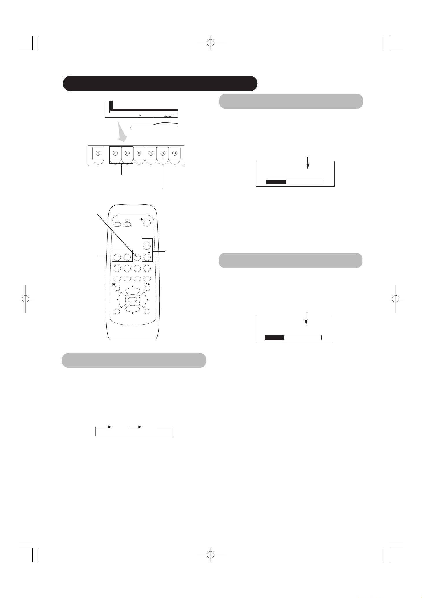
COMPONENT NAMES
Front
Cabinet
(front frame)
Panel
Remote-control
receiver
9
SIZE button
( SELECT button)
15
INPUT SELECT button
(OK button)
14
RECALL button
( SELECT button)
15
• Adjustment buttons are located
on the bottom.
• The back cover is provided with
indications to distinguish the
adjustment buttons.
SUB-POWER button
13
Control panel
VOLUME
UP/DOWN
buttons
( ADJUST
buttons)
14
Main power switch
13
13
• The main power switch is located at the back, on the
lower surface.
▲
▼
(42")
(32")
Indicating lamp
External device connection terminals
Rear
RGB input terminals
11
External
speaker
terminals
Handgrips
HandgripsHandgrips
Main Unit
External
speaker
terminals
11
11
MENU button
16
• ( ) indicates the function while the MENU is displayed on the screen.
01 QR58553-英語-初校03.10.1510:47AMページ8
Page 9
9
ENGLISH
Remote control
ID SET button
16
POWER OFF button
13
POWER ON button
13
POWER ON/OFF button
13
MENU button
16
MUTE button
14
VOLUME UP/DOWN buttons
14
RETURN button
16
RECALL button
15
AUTO button
16
PinP button
34
ID button
16
SELECT/ADJUST buttons
16
OK button
16
Loading Batteries
1. Open the battery cover.
• Slide back and remove the battery
cover in the direction of the arrow.
2. Load batteries.
• Load two Size AA batteries included observing the correct
polarities.
3. Close the battery cover.
• Replace the battery cover in the direction of the arrow and snap
it back into place.
Use the remote control within about 5 m from front of the unit’s
remote-control sensor and within 30 degrees on both sides.
• Do not use new and old batteries together. The batteries could
explode or leak, resulting in fires, physical injury, or stains.
• When loading batteries, observe their correct polarities as
marked on the product. If loaded in the wrong direction, the
batteries could explode or leak, resulting in fires, physical injury,
or stains.
ATTENTION
• Do not drop or impact the remote control.
• Do not splash the remote control with water or put it on a wet
object to avoid possible failures.
• Before leaving the remote control out of use for an extended
period of time, remove the batteries from it.
• If the remote control begins to lack responsiveness, replace the
batteries.
• Strong light such as direct sunlight impinging on the
photoreceptor of the remote control can cause operational
failure. Position this unit to avoid direct contact with such light.
Handling the Remote Control
SIZE button
15
RGB/VIDEO buttons
14
01 QR58553-英語-初校03.10.1510:47AMページ9
VOL
RGB 1 RGB 2
AV1 AV2
AUTO PinP
MENU
ID
MUTE VOL
AV3
SIZE RECALL
OK
AV4
ID SET
CAUTION
With in 30
degrees
About 3m
With in 30
degrees
About 3m
About 5m
VOL
RGB 1 RGB 2
MUTE VOL
AV4
AV1 AV 2
AV3
AUTO PinP
SIZE RECALL
MENU
OK
ID
ID SET
Page 10
10
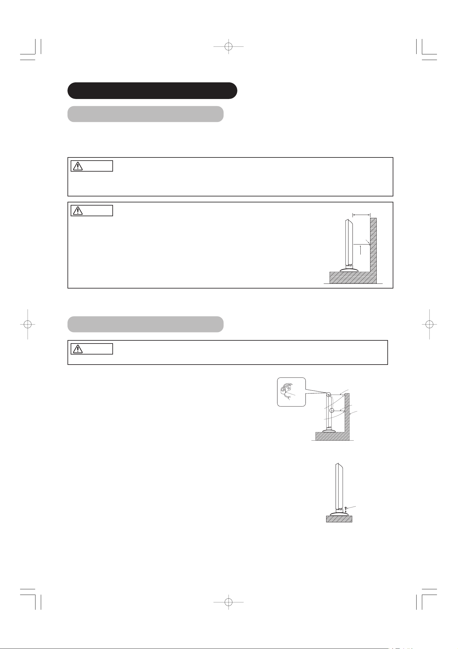
Anti-tumble measures
Securing to a wall or pillar
Using a commercially available cord, chain and clamp, secure the set to a firm wall or pillar.
Securing desktop
1) Using wood screws (two), fasten the set to the clamping screw holes on the rear of the stand as shown.
2) Using commercially available wood screws, secure the set firmly in position.
• If you have purchased the model without the stand attached:
When installing the monitor, use the optional Desk-top Stand (CMPAD23/25).
The Desk-top Stand has been used for the illustrations in this manual.
INSTALLATION INSTRUCTIONS
Installation
• Installation of the wall mount unit and ceiling mount unit can be dangerous, so do not attempt this work
yourself. Ask your dealer to provide the name of a qualified installer.
• In order to prevent an internal temperature increase, maintain a space of 10cm (4 inches : For a desktop setup) or more between the sides and other objects such as walls, etc., so that the ventilation holes are not
blocked.(✻)
Have this unit mounted in a stable place. Take measures to prevent it from tumbling down to avoid possible physical injury.
Use one of the special mount units to install this product. A mount of insufficient strength or inadequate design can cause overturning or
dropping and result in fire, electrical shock or injury. Please note that our company assumes absolutely no responsibility for personal injuries
or property damage caused by use of other mount units or improper installation.
01 QR58553-英語-初校03.10.1510:47AMページ10
WA RNING
CAUTION
10cm (4 inches) or more*
Clamp
Cord
or
chain
CAUTION
Hook
Chain
clamp for 32"
clamp for 42"
cord or chain for 32"
cord or chain for 42"
Wall or Pillar
Wood screw
Two places
Page 11
11
ENGLISH
Read SAFETY INSTRUCTIONS ( to ) carefully to ensure maximum safety before
proceeding to these steps:
• Choose an appropriate site and install the product on a level table where the stand is secure.
• Install the monitor to have ready access to a power socket available.
• Make sure that the power switch of this device is turned off.
74
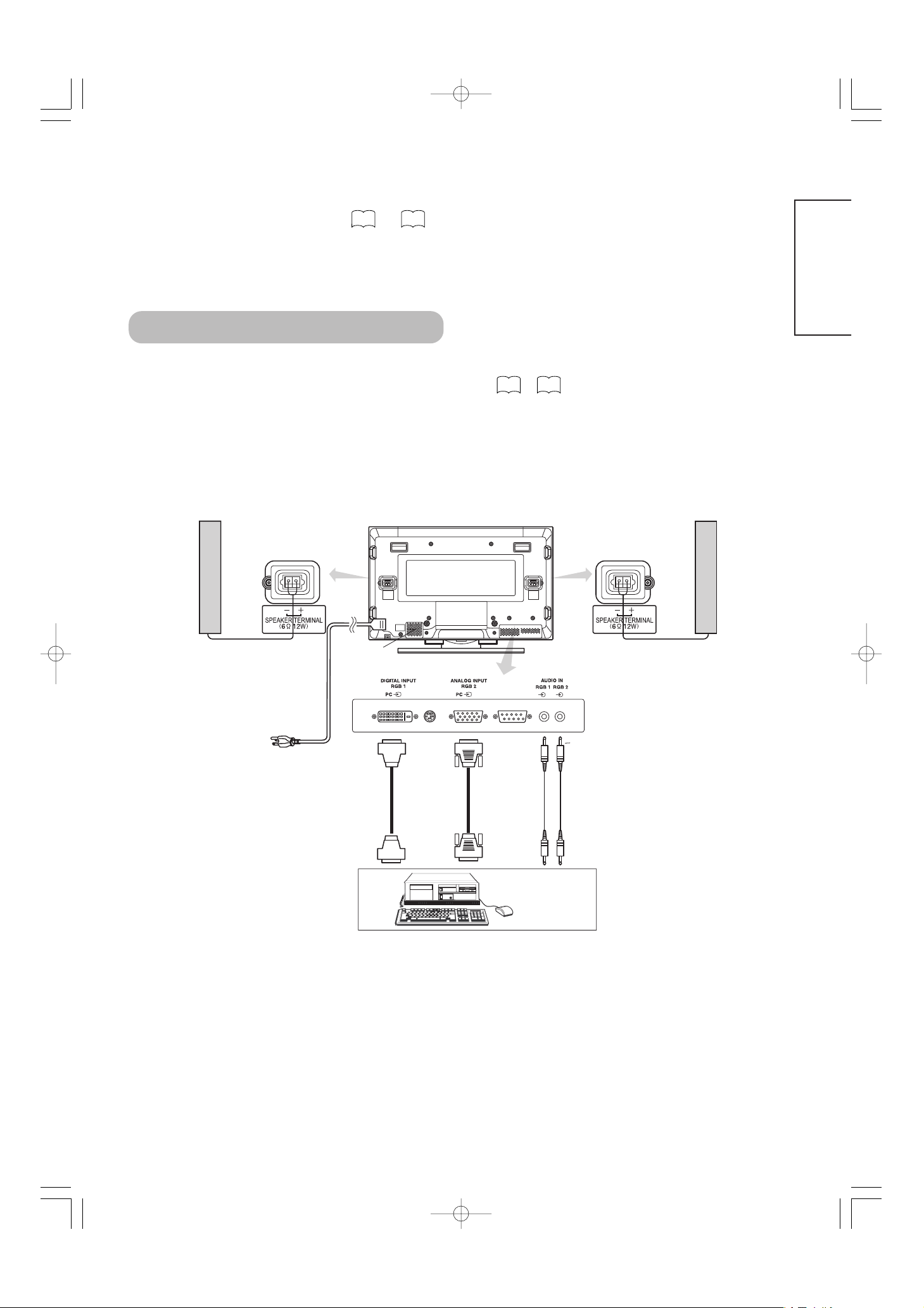
(1) Make sure that the display signal of the personal computer to be used is compatible with the specifications of this
device.
• See "Product Specifications" concerning the specifications of this device.
(2) Make sure that the power switch of the personal computer is turned off.
(3) Connect the signal input terminal (RGB 1 or RGB 2) on the rear panel of this device to the display signal output
terminal of the personal computer.
• Use a cable that fits the input terminal of this device and the output terminal of the personal computer.
• Depending on the type of personal computer being connected, the use of an optional conversion adapter or the adapter provided with
the personal computer may be necessary in some cases. For details, refer to the instruction manual of the personal computer or ask the
personal computer manufacturer or your local retail dealer.
Connecting to a PC
Monitor rear panel
Powe r
cord
Power cable
connector
Speaker (R)
Speaker (L)
PC
(D-sub)(DVI)
To signal
output
terminal
To signal
output
terminal
To audio
output
terminal
3.5mm
Stereo
mini jack
27 29
〜
01 QR58553-英語-初校03.10.1510:47AMページ11
Page 12
12
①①
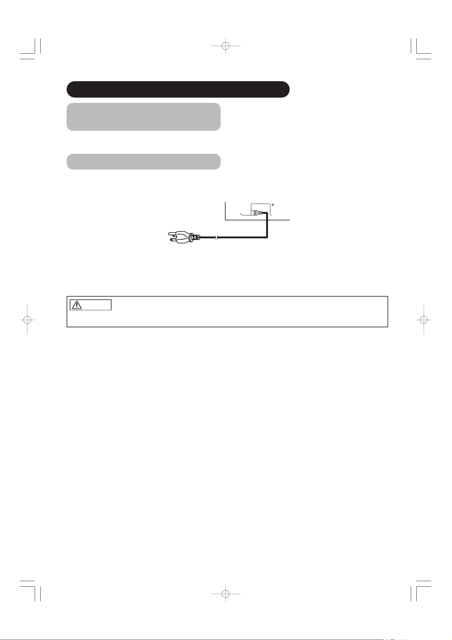
Connect the power cord to this device.
②②
Connect the power cord plug to the power outlet.
(The type of plug is different from this drawing for some countries.)
Connect the power cord, after completing all other connections.
①
②
INSTALLATION INSTRUCTIONS (continued)
Power Cord Connection
• Use only the power cord provided.
• Do not use a power supply voltage other than that indicated (AC100-240V, 50/60Hz) as this may cause fire or electric shock.
Mounting the Speaker Unit
(option)
Refer to the instruction manual concerning mounting of the optional speaker unit.
01 QR58553-英語-初校03.10.1510:47AMページ12
CAUTION
Page 13
13
ENGLISH
OPERATING INSTRUCTIONS
Tur ning Power On and Off
・・
To turn the monitor power ON, press the main power
switch on the monitor main unit to ON, and then press
the SUB POWER button or the ON/OFF or ON button on
the remote control.
・・
To turn the monitor power OFF, press the SUB POWER
button or the ON/OFF or OFF button on the remote
control, and then press the main power switch on the
monitor main unit to OFF.
・
During normal use, the main power switch is set in the ON
position, and the monitor can then be turned ON/OFF using the
SUB POWER button or the ON/OFF button on the remote control.
Indicating lamp
Indicating
lamp
Power status Operating
Off Off
When the main power switch is set
to OFF.
Lights red
Off
(standby)
When the main power switch is
ON, and the OFF button on the
remote control or the SUB POWER
button on the underside of the
front of the frame is OFF.
Lights green On
When the main power switch is
ON, and the ON button on the
remote control or the SUB POWER
button on the underside of the
front of the frame is ON.
Lights orange
Off
(Power Save)
When the main power switch is
ON, and the ON button on the
remote control or the SUB POWER
button on the underside of the
front of the frame is ON.
However, the state in POWER
SAVE mode
When the indicating lamp lights in orange or the message “No Sync.
Signal”, “Power Save” or “Invalid Scan Freq.” appears on the
screen, there is something unusual about the status of reception.
See “Power Save Mode” or “Symptoms That Seemingly Appear to be
Failures.”
POWER OFF
button
POWER ON
button
POWER ON/OFF
button
SUB-POWER button
Main power switch
(42")
(32")
Indicating lamp
ATTENTION
• Avoid repeatedly turning the monitor on and off at short time
intervals. Failures might result from such operation.
• Turn off the main power switch before leaving the monitor out of
use for an extended period of time.
• If a power failure occurs while the main unit is running, it would
be powered on upon recovery from the failure. Turn off the unit
main power switch before leaving the main unit.
22
24
01 QR58553-英語-初校03.10.1510:47AMページ13
RGB 1 RGB 2
AV1 AV2
AUTO PinP
MENU
ID
VOL
MUTE VOL
AV3
AV4
SIZE RECALL
OK
ID SET
Page 14
14
AV1 AV2
RGB 1 RGB 2
AV3
MUTE VOL
VOL
AV4
AUTO PinP
OK
SIZE RECALL
MENU
ID
ID SET
OPERATING INSTRUCTIONS (continued)
Audio Mute
The audio volume can be temporarily mute by pressing
the MUTE button of the remote control.
• When a button is pressed, the volume adjustment
status guide (magenta) will be displayed.
• The volume setting can be lowered by pressing the VOL- button
while the audio is mute.
• The muting can be cancelled by pressing the VOL+ button or
MUTE button while the audio is mute.
When the MUTE button of the remote control is pressed
again, the audio will be restored and the volume display
(green) will appear.
MUTE button
Input Switching
・・
Input can be switched by pressing the RGB1, RGB2,
buttons of the remote control.
・・
Input can be switched in the sequence of RGB1
→→
RGB2 by pressing the INPUT SELECT button of the
monitor.
• When a button is pressed, the volume adjustment
status guide will be displayed.
• The volume will increase when the VOL+ (or ▲) button is
pressed while the guide is being displayed.
• The volume will decrease when the VOL- (or ▼) button is
pressed while the guide is being displayed.
Volume Adjustment
The volume can be adjusted by pressing the VOL+ and
VOL- buttons of the remote control (or the ▲and
▼
volume buttons of the monitor unit).
Volume setting value
Adjustment status guide display
VOLUME
UP/DOWN buttons
INPUT SELECT button
RGB buttons
Adjustment status guide display
(The display color will change to magenta.)
VOLUME UP/DOWN
buttons
▲
▼
Volume setting value
01 QR58553-英語-初校03.10.1510:47AMページ14
Volume 15
Volume 15
RGB1 RGB2
Page 15
15
ENGLISH
Size Switching
Each time the SIZE button of the remote control or the monitor is pressed, the screen display area will change in
sequence and the status will be displayed at the bottom of the screen.
* Real mode gives the image of the same shape as it is displayed on a computer monitor.
This mode is only available for VGA (640 X 480) and WVGA (864 X 480).
SIZE button
AV1 AV2
RGB 1 RGB 2
AV3
MUTE VOL
AV4
AUTO PinP
OK
SIZE RECALL
MENU
ID
ID SET
SIZE button
RECALL button
Input Signal Screen Display
Input mode
Signal mode
Input horizontal frequency
Input vertical frequency
The input signal status can be displayed on the screen by pressing the RECALL button of the remote control or the monitor.
・ The display will go out in approximately 6 seconds.
Off-timer
On-timer
RGB
RECALL button
*
Display area selection diagram (RGB input)
Resolution Full display Circular display
Display Full Normal Real Zoom1 Zoom2 Zoom3
640 X 480
(VGA)
800 X 600
(SVGA)
1024 X 768
(XGA)
1280 X 1024
(SXGA)
1600 X 1200
(UXGA)
Processes such as compression (thinning) and expansion are performed for the above signal display. Because of this, there is a possibility that
flicker may become noticeable on Zoom (1 ~ 3) depending on the display contents. If this occurs, turning the Vertical Filter On can reduce
the flicker.
* VGA and W-VGA
only
20
01 QR58553-英語-初校03.10.1510:47AMページ15
Normal Full Zoom1
Real Zoom3 Zoom2
-- -- Min.
OFF
-- -- : -- --
RGB2
RGB
H : 48.4kHz
V : 60.1 Hz
Page 16
16
AV1 AV2
RGB 1 RGB 2
AV3
MUTE VOL
VOL
AV4
AUTO PinP
OK
SIZE RECALL
MENU
ID
ID SET
ID SET button
ID button
AUTO button
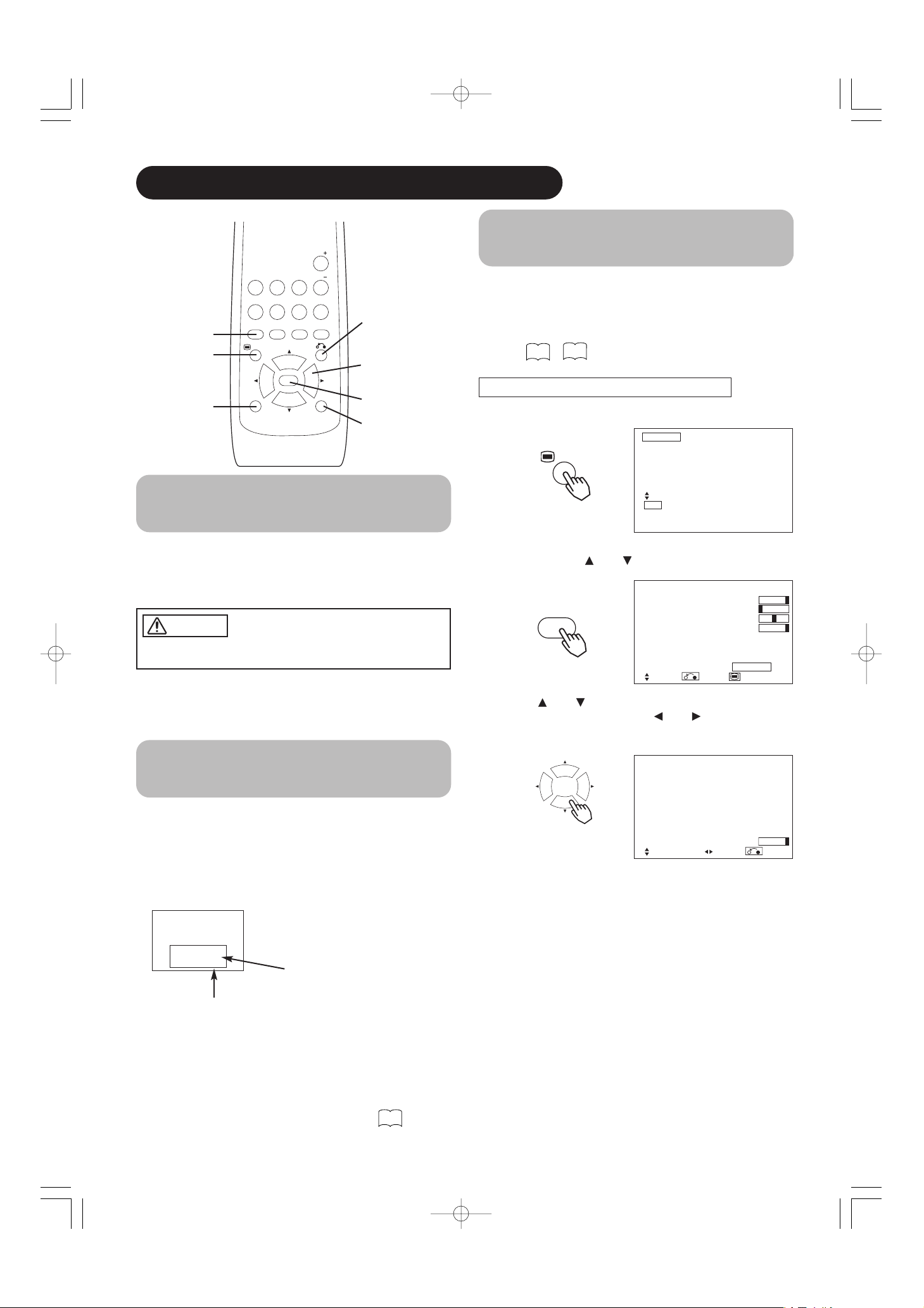
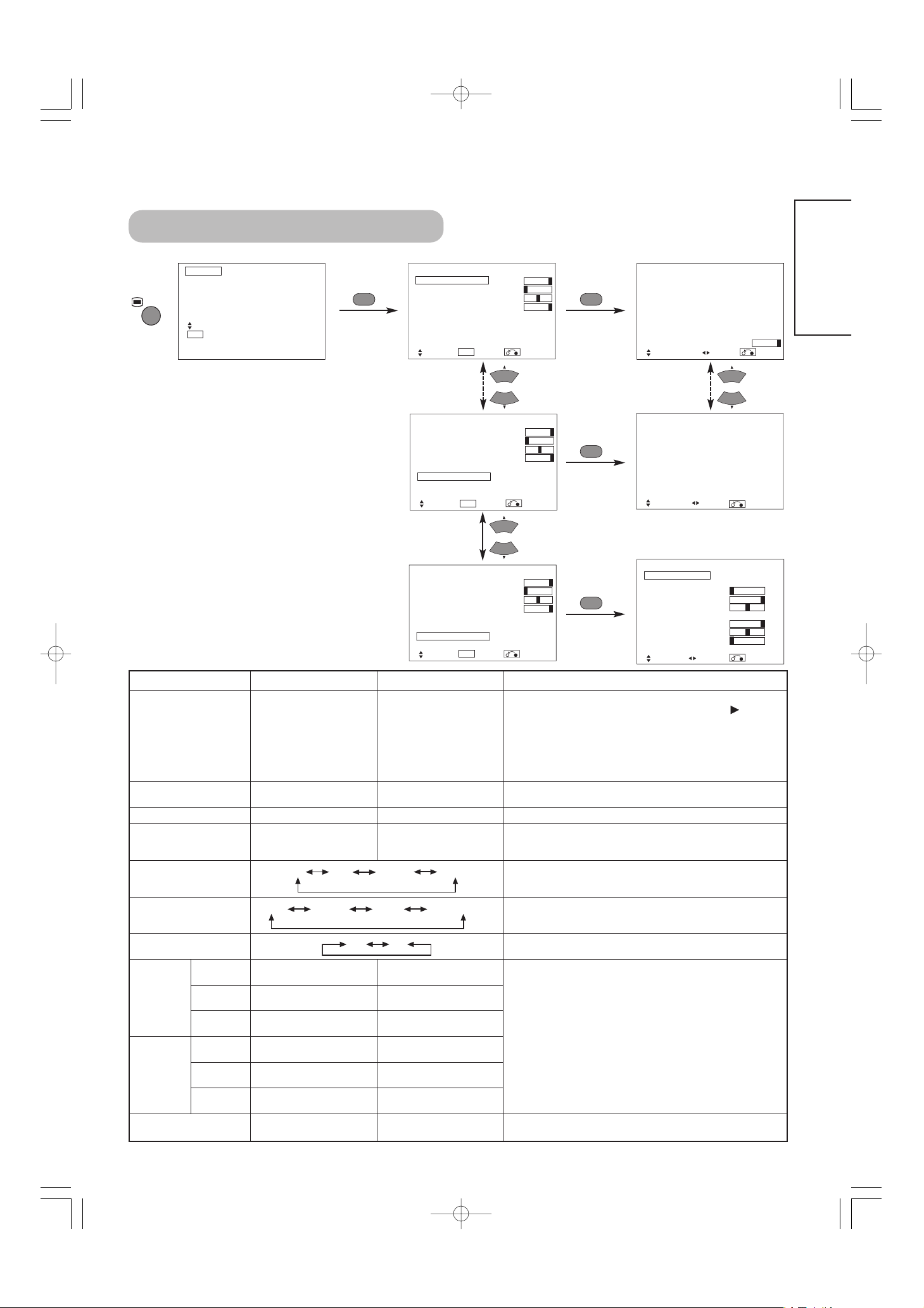
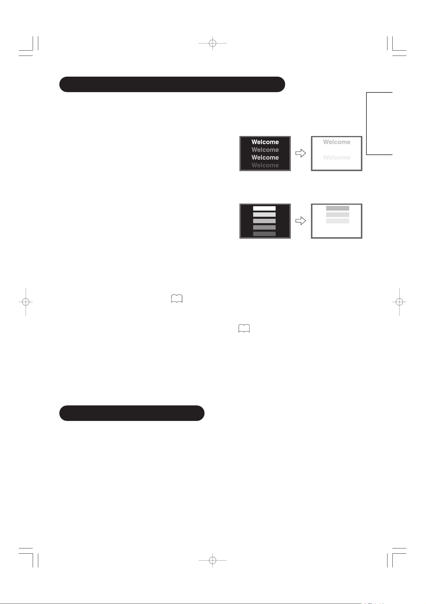
Using the Menu Screen
(On-screen display system)
When the MENU button is pressed, the adjustment menu
screen will be displayed; from there, PC signal adjustment
and setting is possible by using the SELECT button,
ADJUST button and OK button.
• Refer to - concerning the adjustment items and the
settings.
Example: Selecting the Picture screen
1. Press the MENU button to display the Main Menu
screen.
2. Press the OK button to display the Picture Menu
screen. (Use the and SELECT buttons to select
other items.)
3. Use the and SELECT buttons to select the item to
be adjusted and then use the and ADJUST
buttons to adjust (example: Contrast).
• Press the RETURN button to return to the previous screen.
• If there is no operation for a period of one minute, the
Adjustment Menu screen will be closed automatically.
OK
Picture
Contrast : + 31
Brightness : – 31
Color : 0
Tint : + 31
Picture Enhancement : Off
Color Temperature : Normal
Color Temp.Adjust
Reset Reset
Select Return Exit
OPERATING INSTRUCTIONS (continued)
Independent Operation of
Multiple Monitors (ID No)
Setting the ID No. of the remote control allows separate
control of up to a maximum of seven monitors.
Remote control ID No. 2 (initially ID no. 1) can be set by
pressing the ID SET button for 2 sec. or more while
holding down the ID button. The number will be
incremented (2……6→→7→→1→→2) when this button pressed
continuously.
The ID remote control is operated by pressing the
various buttons while holding down the ID button;
Operation is possible only when the remote control and
monitor ID nos. are the same.
• The remote control can be operated normally by pressing the
various remote control buttons without holding down the ID button.
• Set the monitor using the ID No. of Function MENU.
Automatic Adjustment of
Screen Position and the Clock
Adjustment of the screen to a position suitable for the PC
signal and the clock adjustment can be performed
automatically by pressing the AUTO button of the remote
control.
* Depending on the signal, satisfactory adjustment may not be
possible in some cases. In such case, adjust by referring to the
Setup Menu item.
Monitor ID no.
Remote control ID no.
The remote control ID no. can be
checked by pressing the ID SET button
while holding down the ID button.
Perform this adjustment for each input (RGB1 or RGB2) and for
each signal.
19
17
21
MENU button
OK button
SELECT/ADJUST
buttons
RETURN buttons
01 QR58553-英語-初校03.10.1510:47AMページ16
MENU
Picture
Audio
Timer
Function
Setup
Language
Select
OK Set
CAUTION
ID Number
Monitor [ 1 ]
R/C [ 1 ]
Contrast + 31
Next / Prev Adjust Return
Page 17
Selected characters Setup hint
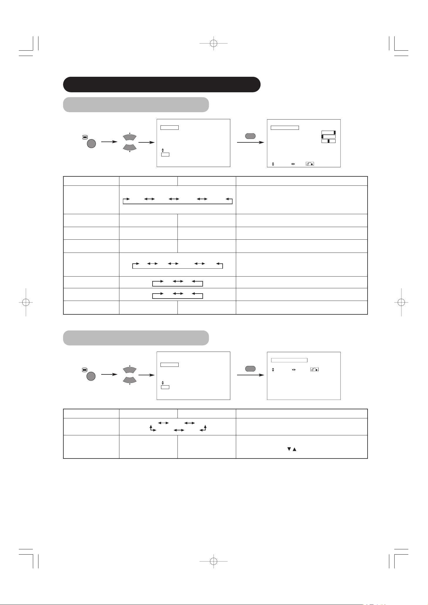
Contrast
Narrows the gap between
brightness and darkness.
Broadens the gap between
brightness and darkness.
Adjust for maximum visibility to suit the ambient brightness.
This can adjust further till [+40] by pressing and holding cursor
button at [+31]. The color for [+32] to [+40] numbers will change from
white to magenta. This special mode is better for dark scenes.
For brighter scene some parts of the picture might not be clear. We
recommend to set at [+31].
"Panel Life" in the Function Menu should be set to Normal when
Contrast setting is adjusted.
Brightness
Black is subdued for
increased overall darkness.
Black is set off for increased
overall brightness.
Adjust to taste.
Color
Darkens colors. Lightens colors. Adjust to taste.
Tint
Enhances red and weakens
green.
Enhances green and weakens
red.
This is not available to adjust when receiving PAL/SECAM signal.
In this case the character will be grayed out.
Adjust for most realistic skin color.
Picture Enhancement
Sets the clarity of small details to the desired level.
Color Temperature
Normally set to Normal.
Color Temp. Adjustment
Turn On when you wish to change color temperature is required to
adjust depending on the user’s preference.
Amplitude
Red
Brighter scene is decreased in
reddish color.
Brighter scene is increased in
reddish color.
Adjust color temperature depending on the user’s preference. These
settings are independently stored in each of the 4 Color Temperature
modes.
Green
Brighter scene is decreased in
greenish color.
Brighter scene is increased in
greenish color.
Blue
Brighter scene is decreased in
bluish color.
Brighter scene is increased in
bluish color.
Cut Off
Red
Dark scene is decreased in
reddish color.
Dark scene is increased in
reddish color.
Green
Dark scene is decreased in
greenish color.
Dark scene is increased in
greenish color.
Blue
Dark scene is decreased in
bluish color.
Dark scene is increased in
bluish color.
Reset
(off the function) (waiting to reset)
The original factory settings for the items of this Menu page can be
restored by pressing the OK button.
17
ENGLISH
PICTURE MENU
▲
▲
Picture
Contrast : + 31
Brightness : – 31
Color : 0
Tint : + 31
Picture Enhancement : Off
Color Temperature : Normal
Color Temp.Adjust
Reset Reset
Select Set Return
OK
Picture
Color Temp. Adjust On
Amplitude
Red – 63
Green 0
Blue – 31
Cut Off
Red + 31
Green 0
Blue + 31
Reset Reset
Select On/Off Return
01 QR58553-英語-初校03.10.1510:47AMページ17
Picture
Audio
Timer
MENU
Function
Setup
Language
Select
OK Set
Picture
Contrast : + 31
OK
Brightness : – 31
Color : 0
Tint : + 31
Picture Enhancement : Off
Color Temperature : Normal
Color Temp.Adjust
Reset Reset
Select Set Return
OK
OK
Contrast + 31
Next / Prev Adjust Return
Picture
Contrast : + 31
Brightness : – 31
Color : 0
Tint : + 31
Picture Enhancement : Off
Color Temperature : Normal
Color Temp.Adjust
Reset Reset
Select Set Return
OK
OK
OK
Color Temperature Normal
Next/Prev Select Return
Off Low Middle High
Cool Normal Warm Black / White
Off On
Page 18
18
Selected characters Setup hint
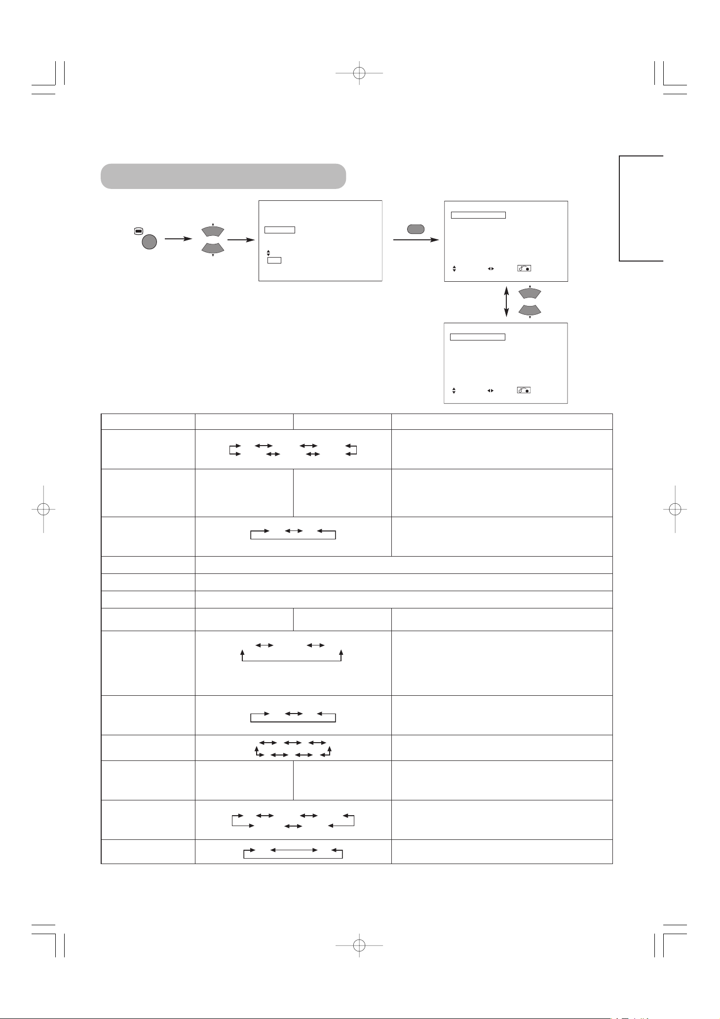
Audio Mode
Movie: This selects the audio suitable for Movie.
Music: This selects the audio suitable for Music.
Speech: This selects the audio suitable for News, Talk show etc.
Favorite: This mode should be adjusted depending on user’s
preference.
Treble
Suppresses treble. Enhances treble. Adjust to taste.
Bass
Suppresses bass. Enhances bass. Adjust to taste.
Balance
Suppresses right-side sound. Suppresses left-side sound. Adjust to taste.
SRS TruBass
SRS TruBass takes advance of the ability of the human ear to be able
to distinguish between two different tones. By using this ability,
TruBass gives enhanced bass sound that otherwise would not be
heard. Adjust it depending on the user’s preference.
Matrix Surround
This features the spacious sound effects of a stadium.
Perfect Volume
This will automatically adjust volume so each channel and input has
the same average volume level.
Reset
(off the function) (waiting to reset)
The original factory settings for the items of this Menu page can be
restored by pressing the OK button.
AUDIO MENU
▲
▲
TIMER MENU
Selected characters Setup hint
Off Timer
This function automatically sets the power to standby status when the
indicated time period has elapsed.
On Timer
- - ( : - - )
hours
(- - : )- minutes
This automatically sets the power from standby to ON when the
indicated time period has elapsed. The settable time is 00:00~11:59.
Input the required time by SELECT buttons on the remote
control.
▲
▲
OPERATING INSTRUCTIONS (continued)
01 QR58553-英語-初校03.10.1510:47AMページ18
Picture
Audio
MENU
Timer
Function
Setup
Language
Select
OK Set
OK
Movie Music Speech Favorite
Off Low Middle High
Off On
Audio
Audio Mode : Movie
Treble : + 10
Bass : – 10
Balance : 0 L R
SRS TruBass : Middle
Matrix Surround : Off
Perfect Volume : Off
Reset Reset
Select Set Return
MENU
Off On
Picture
Audio
Timer
Function
Setup
Language
Select
OK Set
OK
--Min. 30Min. 60Min.
120Min. 90Min.
Timer
Off Timer : 30Min.
On Timer : - - : - -
Select Adjust Return
Page 19
19
ENGLISH
Function
Screen Saver Off
Screen Wipe On 60Min.
Black Side Panel Off
Video Power Save Off
Freeze Mode Split
Default Zoom Panoramic
Reset Reset
Select Set Return
FUNCTION MENU
Selected characters Setup hint
Screen Saver
This moves the picture around the screen in small amounts, at set
intervals, to reduce the panel image retention. This is where
stationary objects, such as screen logos, leave a slight image visible
after they should have disappeared.
Screen Wipe
On 60Min.
This is used to reduce the panel image retention that can occur with
stationary pictures by the white field signal. Select On (continuous
operation) or 60 Min. (time limit operation) and press the OK button.
Press the MENU or RETURN button on the remote control to return to
normal viewing.
Black Side Panel
This turns the gray sidebars On/Off when watching normal mode
screen size area. It is always set to Off when the monitor powered
On. It is recommended to set to Off to reduce the panel image
retention.
Video Power Save
Optional (grayed out)
Freeze Mode
Optional (grayed out)
Default Zoom
Optional (grayed out)
Reset
(off the function) (waiting to reset)
The original factory settings for the items of this Menu page can be
restored by pressing the OK button.
Panel Life
This function is to suppress the contrast of the screen regardless of
the Contrast setting in the Picture Menu. By this control, power
consumption can be reduced or degradation of a panel can be
mitigated.
The order of power consumption is Extend 2 < Extend 1 <
Normal.
If the Contrast setting is changed when this item is set to Extend 1 or
2, it will be changed to Normal automatically.
Mode Display
This can display the Input Signal Screen Display every time the input
mode and signal mode are changed.
Set to OFF if the Input Signal Screen Display is not needed when
switching signals.
ID Number
Assigns ID nos. to the monitors so that they can be controlled
individually (up to 7 monitors can be controlled).
Inverse
On 60Min.
This function can change each level of RGB signal invert to reduce
the panel image retention. When this function is required to use,
select On (continuous operation) or 60Min. (time limit operation) and
press the OK button. And press the Menu or Return button to exit.
Standby White
This function is also provided against the image retention. If time is
set for this item, the screen changes into the white pattern when the
monitor enters power save mode, and it will continue for the period of
setting time.
Gamma
Normally set to 2.2.
▲
▲
01 QR58553-英語-初校03.10.1510:47AMページ19
MENU
Picture
Audio
Timer
Function
Setup
Language
Select
OK Set
OK
Function
Panel Life Normal
Mode Display Off
ID Number 1
Inverse On 60Min.
Standby White Off
Gamma 2.2
Reset Reset
Select Set Return
Off 5Min. 10Min.
60Min. 40Min. 20Min.
Normal Extend 1 Extend 2
1 2 3 4
Off 15Min. 30Min.
120Min. 60Min.
Off On
Off On
7 6 5
2.2 2.8
Page 20
20
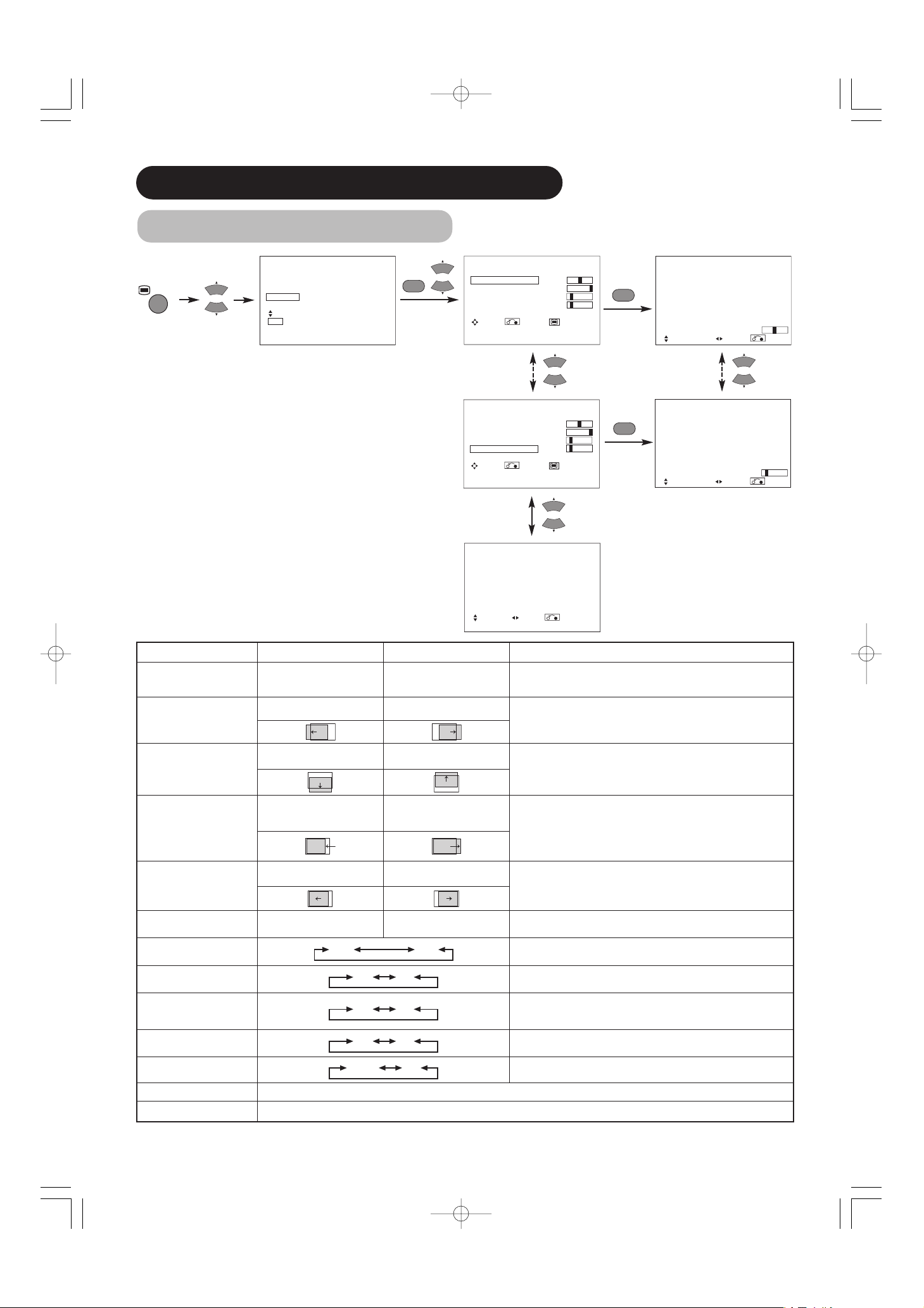
Selected characters Setup hint
Auto Adjust*
(Menu) Adjust
Pressing the OK button here,
Automatic regulation is started.
Horizontal Position, Vertical Position, Horizontal Clock and Clock
Phase are adjusted automatically.
Horizontal Position
Moves the horizontal position
to left.
Moves the horizontal position
to right.
Adjust the left-side display position.
(This function is only for RGB2. It’s not available (grayed out) for
RGB1.)
Vertical Position
Moves down the vertical
position.
Moves up the vertical position.
Adjust the vertical display position.
(This function is only for RGB2. It’s not available (grayed out) for
RGB1.)
Horizontal Clock
Reduces the dot clock
frequency (shrinks the right
side).
Increases the dot clock
frequency (expands the right
side).
Adjust for maximum character clarity.
(This function is only for RGB2. It’s not available (grayed out) for
RGB1.)
Clock Phase
Slows the dot clock phase
(shifts slightly to left).
Advances the dot clock phase
(shifts slightly to right).
Adjust for clear character visibility.
(This function is only for RGB2. It’s not available (grayed out) for
RGB1.)
Reset
(off the function) (waiting to reset)
The original factory settings for the items of this Menu page can be
restored by pressing the OK button. (This is effective only for RGB2.)
Input Level
Normally set to 0.7 V. If white is found to spread across the screen, set
to 1.0 V. (This is effective only for RGB2.)
Frequency Display
Set this to Off if the frequency information of the Input Signal Screen
Display is not required.
WVGA Type
This is only available for W-VGA signal.
When it is set to On, the display area mode can be selected Full or
Real.
Vertical Filter
Turn On when concerned about screen flicker.
Frequency Mode
Set to Movie when viewing moving images on a personal computer.
RGB1
Optional (grayed out)
RGB2
Optional (grayed out)
SETUP MENU
OPERATING INSTRUCTIONS (continued)
* Depending on the type of signal displayed, displays may not be optimized through automatic adjustment. Adjust manually to optimize them.
▲
▲
01 QR58553-英語-初校03.10.1510:47AMページ20
Picture
Audio
Timer
MENU
Function
Setup
Language
Select
OK Set
OK
Setup
Auto Adjust Adjust
Horizontal Position 0
Vertical Position + 31
Horizontal Clock – 20
Clock Phase 10
Reset Reset
Select Return Exit
Setup
Auto Adjust Adjust
Horizontal Position 0
Vertical Position + 31
Horizontal Clock – 20
Clock Phase 10
Reset Reset
Select Return Exit
Setup
Input Level 0.7V
Frequency Display Off
WVGA Type Off
Vertical Filter On
Frequency Mode Movie
RGB1 DVI-PC
RGB2 RGB
Select Set Return
OK
Horizontal Position 0
Next / Prev Adjust Return
OK
Clock Phase 10
Next / Prev Adjust Return
0.7V 1.0V
Off On
Off On
Off On
Movie PC
Page 21
21
ENGLISH
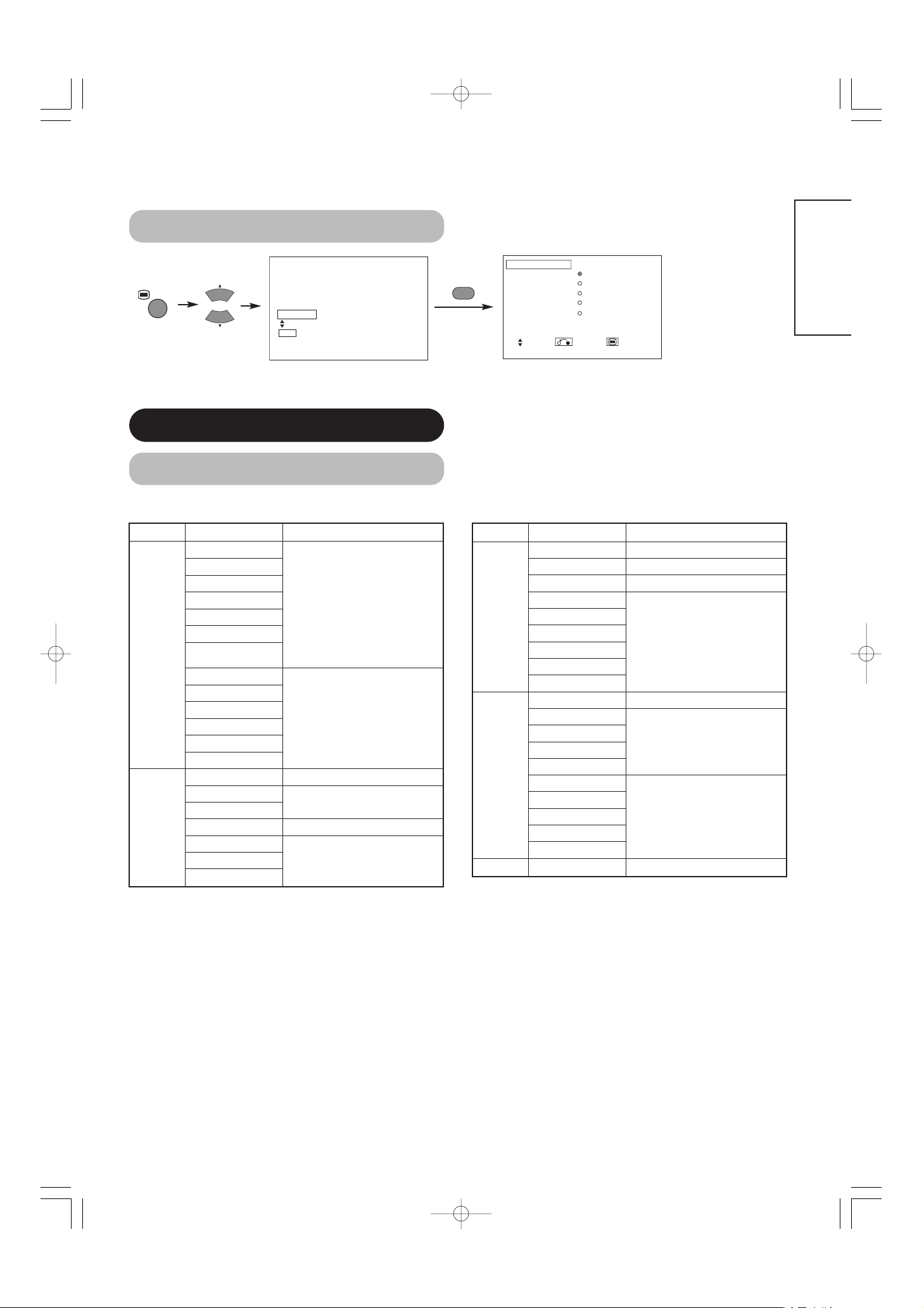
LANGUAGE MENU
Select a language by
▼
▲
SELECT buttons and press the OK button.
OTHER FEATURES
Automatic Store
Approximately 1 sec. after adjustment is completed, the adjustments will be recorded as shown in the table below.
• The previously recorded items will be lost.
• The signal mode can be identified by the horizontal/vertical sync
frequency and the sync signal polarity. Different signals with which
all the elements are the same or similar will be handled as the
same signal.
Menu Display Registration condition
Picture
Contrast
For every input function, 1 setting
is registered.
Brightness
Color
Tint
Picture Enhancement
Color temperature
Color Temp. Adjust
R Amplitude
For every Color Temperature, 1
setting is registered.
G Amplitude
B Amplitude
R Cut Off
G Cut Off
B Cut Off
Audio
Audio Mode 1 setting is registered.
Treble
For every Audio Mode, 1 setting is
registered.
Bass
Balance 1 setting is registered.
SRS TruBass
For every Audio Mode, 1 setting is
registered.
Matrix Surround
Perfect Volume
Menu Display Registration condition
Function
Screen Saver 1 setting is registered.
Screen Wipe (not registered)
Black Side Panel (not registered)
Panel Life
1 setting is registered.
Mode Display
ID Number
Inverse
Standby White
Gamma
Setup
Auto Adjust (not registered)
Horizontal Position
For every signal Mode, 1 setting is
registered. (Only for RGB2)
Vertical Position
Horizontal Clock
Clock Phase
Input Level
1 setting is registered.
Frequency Display
WVGA Type
Vertical Filter
Frequency Mode
Language 1 setting is registered.
01 QR58553-英語-初校03.10.1510:47AMページ21
Language
English
繁體中文
Pycckий
Select Return Exit
簡体中文
日本語
MENU
Picture
Audio
Timer
Function
Setup
Language
Select
OK Set
OK
Page 22
22
Signal Check
Status Display Action
When Mode Display is set to ON,
the input signal is switched or
when the RECALL button is
pressed.
A guide is displayed for the input
terminal and the horizontal and
vertical sync frequency.
When the sync signal is no longer
detected.
• A guide displays No Sync.
Signal, and Power Save (for
approx. 5 sec.)
• When the condition continues
where the sync signal cannot be
detected, indicator lamp of
power source changes in
orange and the mode switches
to power save mode.
Recheck the personal computer
power switch status and the
connection status.
When the input signal does not
match the monitor specifications
or is in an unstable status.
A guide displays Invalid Scan
Freq.
Recheck the input signal
specifications.
27 29
〜
Changes in the signal status are displayed on the screen as they arise.
OTHER FEATURES (continued)
RGB
Power Save Mode
When the RGB1, RGB2 input is selected
• When this unit is connected to a VESA DPMS computer, the Power Save (Off) mode can be set to be activated automatically when the
computer is not being used to reduce power consumption by this unit.
Returning to operating status
• Operate the personal computer, or press either the INPUT SELECT button of the main unit or the RGB1/RGB2 buttons of the remote control.
RGB sync signal
Horizontal Yes No Yes No
Vertical Yes Yes No No
PC signal Active (normal display) Blank (no display)
Operation mode On Off
Indicating lamp Lights green Lights orange
Power consumption
255W (32")
365W (42")
3W or less (RGB1)
1W or less (RGB2 ; 100V≦AC≦120V)
3W or less (RGB2 ; 120V<AC≦240V)
01 QR58553-英語-初校03.10.1510:47AMページ22
-- -- Min.
OFF
-- -- : -- --
RGB2
RGB
H : 48.4kHz
V : 60.1 Hz
! No Sync. Signal
! Invalid Scan Freq.
Page 23
23
ENGLISH
NOTES
About screen defects
• High precision technology is used in the making of plasma panels but there may be dark spots (points that do not illuminate) and bright spots
(points that are too bright) in some cases. These do not indicate a malfunction.
About residual images
• In some cases, residual images may remain after the short-term display of still images and another image is displayed, but these will
disappear and return to normalcy. This is not a malfunction.
About the panel screen
• Plasma displays display images by means of electrical discharges inside the panel. Because of this, the temperature of the panel surface may
rise in some cases.Also, plasma displays are made of finely processed glass. A reinforced glass filter is installed over the panel surface but
avoid strong impact because there is still danger of glass breakage.
IMAGE RETENTION OF PLASMA DISPLAY
There are different characteristics that result in panel image retention depending on how the plasma display is used.
Situations and effective usage methods related to ghosting are provided below.
Image retention characteristics of a plasma display
The image retention phenomenon of a plasma panel occurs due to partial phosphor degradation arising from partial character and figure
display.
For example, when the character image as shown in Fig. A at the right is
continuously displayed for a long period of time, the only part of the phosphor
(Red,Green, Blue) that will degrade will be the color of the applicable character
display portion. Consequently, when a white image is displayed on the entire
screen as shown in Fig. a, the character marks displayed up to that time will
become a color difference visible to the eye, but the phosphor will never burn.
■
The degree of image retention is proportional to the brightness of the characters and figures displayed as well as the display time.
• The tendency of the phosphor is to degrade more the brighter the characters
and figures are displayed. When images of figures with different levels of
brightness, as shown in Fig. B, are continuously displayed for a long period of
time, it becomes easier for image marks at locations when the brighter figures
are displayed to be noticeable.
*
The image retention images in this document are exaggerated for the purpose of explanation. The actual manner in which the image retention
is seen differs depending on the operation time and brightness.
Methods to Reduce the Occurrence of Image Retention
• Lower the Contrast and Brightness settings of the plasma display as much as possible.
A function is provided in the display that controls the brightness of the screen to reduce degradation of the panel. Using this function makes it
possible to reduce image retention.
(Refer to Panel Life (Extend 1.or Extend 2 shown on )
• Set the plasma monitor to an “Screen Wipe” or “Inverse” display.
The occurrence of image retention when displaying images of identical patterns, such as static images, for long periods of time can be
reduced by displaying a reversed color or completely white screen for about 1 ~ 2 hours after terminating the display.
(Settings can be made using Screen Wipe and Inverse of Function MENU shown on )
• Using in combination with moving images
Since the degradation of the fluorescent material progresses comparatively uniform for moving images, the occurrence of partial image
retention can be controlled. We recommend to use in combination with moving images such as a DVD.
* Please be careful since image retention will occur if display is left in a two screen display state for a long period of time.
* Television broadcasts include images displayed for long periods of time in which the left and right or top and bottom of the image are cut and
broadcast station name or time are displayed for a long period of time at the same portion of the screen. Image retention in these portions can
be expected to occur, so please be aware.
【
Fig. A
】【
Fig. a
】
【
Fig. B
】【
Fig. b
】
19
19
01 QR58553-英語-初校03.10.1510:47AMページ23
Page 24

24
Symptoms That Seemingly Appear to be Failures
Make the checks suggested below depending on the symptoms observed. If the symptoms remain uncorrected, contact your dealer.
TROUBLESHOOTING
Customer servicing can be hazardous.
Symptom Point to check See page
• No picture with the power-indicating lamp
off.
• Check the way the power cable is connected.
• Press the power switch.
• The message “No Sync. Signal” or “Power
Save” is displayed.
• No picture with the power indicating lamp
lights in orange.
No sync signal is detected.
• Check the way the signal cable is connected.
• Make sure that the switch of the computer, imaging equipment ,
etc., is turned on.
• Make sure the computer is not in the power-save mode.
• Check to see if the input selection matches the connection
terminal.
• The message “Invalid Scan Freq.” is
displayed.
An input signal is not received normally.
• Check to see if the input signal matches the monitor
specifications.
• Check the way the signal cable is connected.
• The power indicating lamp is normally lit but
no picture .
• Check the contrast and brightness settings (adjust them for higher
contrast and brightness).
• Check the way the signal cable is connected.
• The display image appears flowing
slantwise.
• Text displayed across the screen appears
vertically streaked, with the characters in
vertical columns blurred.
• Adjust the dot clock frequency and phase. (Adjust the dot clock
frequency first, the dot clock phase next.)
(RGB input)
• Text displayed across the screen appears
blurred.
• A fine pattern flickers when displayed on the
screen.
• Adjust the dot clock phase for the clearest viewing.
(RGB input)
• The remote control does not work. • Check to see if the batteries are loaded in the remote control in
opposite direction.
• Check to see if the batteries in the remote control are OK.
28
11
11
13
12
29
26
26
9
17
11
20
20
01 QR58553-英語-初校03.10.1510:47AMページ24
WA RNING
! No Sync. Signal
! Invalid Scan Freq.
Page 25

25
ENGLISH
Symptom Point to check See page
• The temperature of the display panel surface is high. • The plasma display panel is lighting the phosphors by the
discharge of internal radiation. In some cases, this may cause the
temperature of the panel surface to increase. Please note that this
is not a malfunction.
-
• There are locations on the screen that are different from the
periphery (*).
*Points that do not light, points with brightness different
from that of the periphery, points with color different from
that of the periphery, etc.
• High-precision technology is used to manufacture the plasma
display panel, However in some cases, there are minor defects in
some parts of the screen. Please note that this is not a
malfunction.
-
• Vertical stripes appear, depending on the screen contents. • The plasma display panel is lighting the phosphors by the
discharge of internal radiation. Depending on the screen
contents, in rare cases this may cause vertical stripes to appear
because of failure to light. Please note that this is not a
malfunction.
-
• Coarse horizontal stripes appear in FULL display. • Adjusting the Clock Phase will reduce the horizontal stripes.
(RGB input)
• Flickering in the form of horizontal lines oscillating up and
down.
(PC INPUT MODE only)
• If the direct frequency from the computer is below 85Hz, try a
higher frequency (upper limit 85Hz). There may be a slight
attenuation of the current image.
• Try turning the Vertical Filter On. For this case however, the
vertical resolution will drop.
• The fan motor is noisy. (Fan application model only) • Use the fan that controls the temperature in the main body to
lower the temperature of this unit. If the ambient air temperature
increases, the fan will start, the RPMs will increase and motor
noise will grow louder. This is not a malfunction though.
-
• The top of the monitor heats up. • When used for long periods of time, the top of the monitor may
heat up. This is not a malfunction.
-
• Text characters are displayed with varying thicknesses. • The thicknesses of characters and lines may vary if images with a
vertical resolution greater than 512 lines are displayed; however,
this is not a malfunction.
-
20
20
01 QR58553-英語-初校03.10.1510:47AMページ25
Page 26

26
Depending on the kind of system equipment used, images may not be displayed normally. In this case, make the
adjustments suggested below. (only for RGB2)
Actions to Correct Abnormal Displays
Symptom 1
Text displayed across the screen appears vertically streaked, with some characters blurred (figure 1).
The display image appears flowing (figure 2) (RGB input).
Example
r
Adjustment
procedure
1) Press the AUTO button on the remote control.
When adjustment is not possible with Auto Adjust
2) Press the MENU button. The Main Menu will be displayed.
3) Press the SELECT button and select Setup.
4) Press the OK button. The Setup Menu will be displayed.
5) Press the SELECT button and select Horizontal Clock.
(Display fine patterns as characters or a vertical striped pattern over the entire screen during Horizontal Clock adjustment.)
6) Press the or ADJUST buttons and search for clear characters over the entire screen.
7) Perform adjustment for symptom 2 below, when the characters are blurred on the entire screen.
• The display image may be momentarily disturbed during clock adjustment but this is not a failure.
Symptom 2
Text displayed across the screen appears blurred in its entirety (figure 2).
A fine pattern flickers when displayed on the screen (figure 3).
Example
Adjustment
procedure
1) Press the AUTO button on the remote control.
When adjustment is not possible with Auto Adjust
2) Press the MENU button. The Main Menu will be displayed.
3) Press the SELECT button and select Setup.
4) Press the OK button. The Setup Menu will be displayed.
5) Press the SELECT button and select Clock Phase.
(Display fine patterns as characters or a vertical striped pattern over the entire screen during Clock Phase adjustment.)
6) Press or ADJUST buttons to make the text appear
clean across the screen.
6) Press or ADJUST buttons to make the text appear
without flickering.
TROUBLESHOOTING (continued)
Figure 2
Figure 3
Figure 1
01 QR58553-英語-初校03.10.1510:47AMページ26
Vertical
Before adjustment
streaks
ABCDEFGHIJ
abcdefgABCDEFGabcd
ABCDEFGHIJ
abcdefgABCDEFGabcd
Some characters
are blurred.
ABC
B
ABC
ABC
ABC
After adjustment
All characters appea
crisp now.
After adjustment
All characters are
blurred.
ABCDEFGHIJ
abcdefgABCDEFGabcd
ABCDEFGHIJ
abcdefgABCDEFGabcd
Before adjustment
ABC
ABC
After adjustment
ABC
Before adjustment
After adjustment
Page 27

27
ENGLISH
Product specifications and designs are subject to change without notice.
PRODUCT SPECIFICATIONS
• The monitor takes at least 30 minutes to attain the status of optimal picture quality.
Signal Input
RGB terminal (D-sub 15-pin connector)
• When different kinds of input signals are simultaneously input to
the monitor via a graphics board or the like, the monitor will
automatically select the signals in the following priority order:
*Even in the case of the recommended signals shown on the
following page, there may be instances when correct display is
not possible. In this case, use H/V separate sync, H/V composite
sync.
Panel
Display
dimensions
Approx. 32 inches (716 (H) x 399 (V) mm, diagonal 820mm) Approx. 42 inches (922 (H) x 522 (V) mm, diagonal 1059mm)
Resolution
852 (H) x 1024 (V) pixels 1024 (H) x 1024 (V) pixels
Net dimensions
(excluding Speakers/Stand)
830 (W) x 506 (H) x 92 (D) mm 1030 (W) x 636 (H) x 91 (D) mm
Net weight
(excluding Speakers/Stand)
24.6kg 34.9kg
Ambient
conditions
Temperature
Operating : 5˚C to 35˚C, Storage : 0˚C to 40˚C
Relative humidity
Operating : 20% to 80%, Storage : 20% to 90% (non-condensing)
Power supply
AC100 - 240V, 50/60Hz
Power consumption/at standby
255W / <3W 365W / <3W
Audio output
12W + 12W (6Ω)
(RGB input)
Input signals
Input terminals
RGB1 DVI input terminal (DVI-D)
RGB1 audio input terminal (3.5mm Stereo Mini Jack)
RGB2 analog RGB input terminal (D-sub 15-pin)
RGB2 audio input terminal (3.5mm Stereo Mini Jack)
Video signals
0.7 V/1.0 Vp-p, analog RGB (Recommended Signal)
Sync signals
H/V separate, TTL level [2KΩ]
H/V composite, TTL level [2KΩ]
Sync on green, 0.3 Vp-p [75Ω]
Recommended signal
43 modes
Sync signal type Priority
H/V separate sync. 1
H/V composite sync. 2
sync.on Green * 3
28
Pin
Input signal
1 R
2 G or sync on green
3 B
4 No connection
5 No connection
6 R.GND
7 G.GND
8 B.GND
9 No connection
10 GND
11 No connection
12 [SDA]
13 H. sync or H/V composite sync
14 V.sync. [V.CLK]
15 [SCL]
29
01 QR58553-英語-初校03.10.1510:47AMページ27
10
12345
6789
1112131415
Page 28

28
Signal Input (continued)
PRODUCT SPECIFICATIONS (continued)
DVI terminal (DVI-D)
Pin Input signal Pin Input signal
1
T.M.D.S. Data2-
14
+5V Power
2
T.M.D.S. Data2+
15
Ground (for+5V)
3
T.M.D.S. Data2/4 Shield
16
Hot Plug Detect
4
T.M.D.S. Data4-
17
T.M.D.S. Data0-
5
T.M.D.S. Data4+
18
T.M.D.S. Data0+
6
DDC Clock
19
T.M.D.S. Data0/5 Shield
7
DDC Data
20
T.M.D.S. Data5-
8
No Connect
21
T.M.D.S. Data5+
9
T.M.D.S. Data1-
22
T.M.D.S. Clock Shield
10
T.M.D.S. Data1+
23
T.M.D.S. Clock+
11
T.M.D.S. Data1/3 Shield
24
T.M.D.S. Clock-
12
T.M.D.S. Data3-
Frame GND
13
T.M.D.S. Data3+
With Digital RGB signal input (RGB1 input)
Recommended Signal List
No.
Signal mode
Horizontal frequency
(kHz)
Dot clock frequency
(MHz)
Remarks
Signal Name Resolution
Vertical frequency
(Hz)
1
VGA
640X400 70.08 31.47 25.18
2 640X480 59.94 31.47 25.18
3
W-VGA
864X480 60.00 31.02 33.75
4 864X480 59.94 31.47 34.24
WVGA type : On
5
VESA
640X480 72.81 37.86 31.50
6 640X480 75.00 37.50 31.50
7 640X480 85.01 43.27 36.00
8 800X600 56.25 35.16 36.00
9 800X600 60.32 37.88 40.00
10 800X600 72.19 48.08 50.00
11 800X600 75.00 46.88 49.50
12 800X600 85.06 53.67 56.25
13 1024X768 60.00 48.36 65.00
14 1024X768 70.07 56.48 75.00
15 1024X768 75.03 60.02 78.75
• Make sure that the signal of the equipment to be connected is compatible with the specifications of this list.
01 QR58553-英語-初校03.10.1510:47AMページ28
12345678
910111213141516
17 18 19 20 21 22 23
24
Page 29

29
ENGLISH
• The type of video board or connecting cable used may not allow for correct displays adjustment of Horizontal Position, Vertical Position, Horizontal
Clock and Clock Phase.
• The monitor may fail to display an animation image correctly when a signal having a vertical frequency of 85Hz or higher is input to it.
• The monitor differentiates the signal modes according to the horizontal and vertical frequencies and the horizontal and vertical sync signal
polarities. Note that different signals having all these elements alike may be handled as the same signal.
• Displaying images with more than 512 lines of vertical resolution at Full diplay (compressed display) can result in the interpolation of stripes.
No.
Signal mode
Horizontal frequency
(kHz)
Dot clock frequency
(MHz)
Remarks
Signal Name Resolution
Vertical frequency
(Hz)
1
VGA
640X400 70.08 31.47 25.18
2 640X480 59.94 31.47 25.18
3 W-VGA 864X480 59.94 31.47 34.24 WVGAtype:On
4
VESA
640X480 72.81 37.86 31.50
5 640X480 75.00 37.50 31.50
6 640X480 85.01 43.27 36.00
7 800X600 56.25 35.16 36.00
8 800X600 60.32 37.88 40.00
9 800X600 72.19 48.08 50.00
10 800X600 75.00 46.88 49.50
11 800X600 85.06 53.67 56.25
12 1024X768 60.00 48.36 65.00
13 1024X768 70.07 56.48 75.00
14 1024X768 75.03 60.02 78.75
15 1024X768 85.00 68.68 94.50
16 1152X864 75.00 67.50 108.00
17 1280X1024 60.02 63.98 108.00
18 1280X1024 75.03 79.98 135.00
19 1280X1024 85.02 91.15 157.50
20 1600X1200 60.00 75.00 162.00
21 1600X1200 75.00 93.75 202.50
22 1600X1200 85.00 106.25 229.50
23
Macintosh
640X480 66.67 35.00 30.24
24 832X624 74.55 49.72 57.28
25 1024X768 74.93 60.24 80.00
26 1152X870 75.06 68.68 100.00
27
W-XGA
1280X768 59.833 47.986 81.00
28 1280X768 69.997 56.137 94.760
With Analog RGB signal input (RGB2 input)
01 QR58553-英語-初校03.10.1510:47AMページ29
Page 30

30
SUPPLEMENT
01 QR58553-英語-初校03.10.1510:47AMページ30
Page 31

31
ENGLISH
Optional Video Unit Function
Additional functions when the optional video unit is installed are as follows: ( )
( )
Use if the
video
equipment
has an
S video
input terminal
To S video output
terminal
To audio output
terminals
To audio output
terminals
To component
output terminals
To component
output terminals
To component
input terminals
To component
input terminals
To composite
input terminal
To audio output
terminals
To audio input
terminals
20 18 16 14 12 10 8 6 4 2
21
19 17
15 13 11 975
31
VTR
VTR
DVD player Set-Top Box
Video disc player
Adaptor
To composite
output terminal
S-video/Composite video
Do not connect both
plugs at the same time.
Use either of them.
S-video can not
be used.
Adaptor
with Cable
(32") (42")
(1) Make sure that the power switch of the monitor is turned off.
(2) Make sure that the power switch of the imaging device is turned off.
(3) Use a commercially available cable and connector to connect the signal input terminal on the rear panel of this
device and the signal output terminal of the imaging device.
INSTALLATION INSTRUCTIONS
Connecting to a Video Imaging Device
• If video equipment with an S video output terminal is used, cabling
by the S video cable is recommended to provide finer video
quality. (If an S video input terminal and a video input terminal of
AV3 connect to the monitor at the same time, S video input would
govern.)
• If the OUTPUT (MONITOR) terminal is connected to an external
monitor with a 75 Ohm terminal, it is possible to view the same
image as on the main unit. But it is possible to monitor only the
composite video signal from AV1, AV2, AV3 or AV4 input that is
displayed on the screen at the time.
• If the adaptor is applied to AV4 input as shown in the drawing, it is
not possible to receive RGB signal.
With RGB component setup
To component video
equipments.
Please use the connection
cable suitable for the terminal
form of video equipment.
[An example of connecting video imaging devices]
31 42
〜
Applicable video signals for each input terminal (See PRODUCT SPECIFICATIONS for details. )
Terminal RCA/SCART DVI D-sub Remarks
Signal CVBS S-video Component RGB PC STB RGB Component
AV1
○ ○
AV2
○ ○ ○
Refer to Setup Menu.
AV3
○ ○
AV4
○ ○ ○
Refer to Setup Menu.
RGB1
○ ○
Refer to Setup Menu.
RGB2
○ ○
Refer to Setup Menu.
(
○ :Available)
40
38
38
39
39
01 QR58553-英語-初校03.10.1510:47AMページ31
Speaker (R)
Monitor rear panel
Power
cord
Speaker (L)
Page 32

32
OPERATING INSTRUCTIONS
Input Switching
AV1 AV 2
RGB 1 RGB 2
AV3
MUTE VOL
VOL
AV4
AUTO PinP
OK
SIZE RECALL
MENU
・・
Input can be switched by pressing the AV1, AV2, AV3,
AV4, RGB1 or RGB2 buttons of the remote control.
・・
Input can be switched in the sequence of AV1 →→AV2
→→
AV3 →→AV4 →→RGB1 →→RGB2 by pressing the INPUT
SELECT button of the monitor.
INPUT SELECT button
RGB/VIDEO
buttons
SIZE button
Each time the SIZE button of the remote control or the
monitor is pressed, the screen display size will change in
sequence and the status will be displayed at the bottom
of the screen.
Size Switching
• During VIDEO signal input (AV1, AV2, AV3, AV4, RGB1
(set to [DVI-STB]) and RGB2 (set to [Component]))
• The size will fix as Full mode and not change when receiving the
component signal of 1080i/50, 1080i/60 or 720p/60.
Display size selection diagram
When you want to
Set the display size to
Input signal Display screen Remarks
Play a 4:3 image in a 16:9 screen faithfully.
4:3
Blanking occurs on both sides.
Play a 4:3 image in a 16:9 screen with the
height and width of the middle of the
screen enlarged on equal scales and with
both sides appearing somewhat enlarged.
Panoramic
Play a 16:9 VISTA size image in the 4:3
image faithfully reproduced on the 16:9
screen.
Zoom
• The 4:3 image is called a letterbox image.
• In some cases, some slight blanking may
remain at the top and bottom.
Play a 21:9 Cinema size image in the 4:3
image expanded vertically on the 16:9
screen.
Cinema
In some cases, some slight blanking may
remain at the top and bottom.
Play a 4:3 image faithfully in a 16:9 screen
in the standard vertical size and
horizontally squeezed.*
Full
* An image with an aspect ratio of 16:9
shrunk horizontally to 4:3 to display in a 4:3
screen
(4:3 signal)
(Squeeze)
(Vista)
(Cinema)
SIZE button
01 QR58553-英語-初校03.10.1510:47AMページ32
4:3 Panoramic Zoom
Full Cinema
Full
AV1 AV2 AV3
RGB2 RGB1 AV4
Page 33

33
ENGLISH
ATTENTION
Using a wide-screen monitor
• This monitor has a screen mode selection feature. If an incompatible screen mode is selected to play certain software, such as a TV program,
the image would appear different from the original. Take this into consideration when making screen mode choices.
• Use of this monitor in its enlarged display mode with the wide feature enabled in coffee shops, hotels and other establishments for
commercial or pubic viewing purposes could infringe on the copyright holder’s right protected by Copyright Law.
• When a normal 4:3 image is displayed over the entire screen in the Panoramic mode, parts of the periphery of the image may disappear
and/or appear distorted in some cases. Use the 4:3 mode to view images, which were created in 4:3 mode.
This mode allows 4:3 content to be viewed without picture distortion.
Press
Vertical picture position can be adjusted for [Panoramic], [Zoom] and [Cinema] mode as follows.
1. Press SIZE button and SELECT buttons during picture size display.
2. Position display will appear.
3. Adjustment range of each picture size are as shown below.
[Panoramic] - 12 to + 12
[Zoom] and [Cinema] - 31 to + 31
4. When 1080i/50 or 1080i/60 component signal is received, vertical position can be adjusted only one step up. (The range: 0 to +1)
Position + 31
Position - 31
Press
01 QR58553-英語-初校03.10.1510:47AMページ33
Page 34

34
OPERATING INSTRUCTIONS (continued)
Displaying MULTI PICTURE
If the PinP button on the remote control is pressed MULTI
PICTURE will display.
Activating the P-in-P mode from the RGB input screen
Pressing the PinP button one time will display 2 pictures.
• This mode can be available from RGB1(DVI-PC) and RGB2(RGB)
input.
• The speaker icon can be shifted left and right by pressing the
and SELECT buttons; the audio of the video will be output from
the side on which the speaker icon is located.
• The sub-screen position can be
selected up and down by pressing
SELECT buttons.
• The sub-screen can be selected with
the AV1, AV2, AV3, and AV4 buttons
from the status that the speaker icon
appears on the left side of AV✱ as
shown in the diagram to the right.
• Pressing the PinP button again or
the RETURN button will cancel the 2 pictures display.
• "Frequency Mode" in the Setup Menu should be set to Movie when
sub-screen is the component signal of 1080i/50 or 1080i/60.
AV1: Displays the VIDEO input signal of the sub-screen.
Activating the Split mode from the video input screen
Pressing the PinP button one
time will display 2 pictures.
• The speaker icon can be shifted left
and right by pressing the and
SELECT buttons; the audio of the
video will be output from the side on
which the speaker icon is located.
• The same video input mode cannot
be selected for both screens at the
same time.
• Pressing the PinP button again or the RETURN button will cancel
the 2 pictures display.
•
When the Video input is set to RGB Video, this Split mode is not possible.
•
Refer to the table for 2 pictures (Split) mode.
PinP button
RETURN button
AV1 AV2
RGB 1 RGB 2
AV3
MUTE VOL
VOL
AV4
AUTO PinP
OK
SIZE RECALL
MENU
ID
ID SET
RECALL button
AV1 AV 2
RECALL button
2 Pictures (Split)
The input signal status can be displayed on the screen
by pressing the RECALL button of the remote control or
the monitor.
・ The display will go out in approximately 6 seconds.
Input Signal Screen Display
Input mode
Signal mode
Off-timer
On-timer
VIDEO
NOTE
• Even if the input of the horizontal / vertical synchronizing signal (or video signal) stops in the MULTI PICTURE display, the mode will not
change to power save mode.
• Please be careful since image retention will occur if display is left in a MULTI PICTURE display state for a long period of time.
Input terminal
AV1〜AV4
AV1, AV2 RGB1 RGB2
PAL
SECAM
NTSC3.58
NTSC4.43
576i
576p
480i
480p
1080i/50 1080i/60 720p/60 STB Component
AV1
〜
AV4
PAL, SECAM
○ ○ ○ ○ ○ ○ ○
NTSC3.58/4.43
○ ○ ○ ○ ○ ○ ○
AV1
AV2
576i, 576p
○ ○
480i, 480p
○ ○
1080i/50
○ ○
1080i/60
○ ○
720p/60
○ ○
RGB1 STB
RGB2 Component
○ ○ ○ ○ ○ ○ ○
(
○ :Available)
Main
Sub
01 QR58553-英語-初校03.10.1510:47AMページ34
-- -- Min.
OFF
-- -- : -- --
RGB2
AV1
Main Sub
AV1
Composite
(Subscreen)
Page 35

35
ENGLISH
Auto Color Off
Next/Prev On/Off Return
Picture
Color Management On
Magenta + 60
Red + 30
Yellow 0
Green + 60
Cyan + 30
Blue 0
Reset Reset
Select On/Off Return
OK
PICTURE MENU
Picture Dynamic
YNR Off
CNR Off
Film Mode On
PAL Comb Filter On
LTI Off
CTI Off
Black Enhancement Off
Auto Color Off
Reset Reset
Select Set Return
OK
Picture
Color Temp. Adjust On
Amplitude
Red – 63
Green 0
Blue – 31
Cut Off
Red + 31
Green 0
Blue + 31
Reset Reset
Select On/Off Return
01 QR58553-英語-初校03.10.1510:47AMページ35
MENU
Picture
Audio
Timer
Function
Setup
Language
Select
OK Set
Picture
OK
Picture Mode Dynamic
Contrast +31
Brightness -31
Color 0
Sharpness +15
Tint 0
Color Temperature Normal
Contrast Mode Normal
Reset Reset
Select Set Return
OK
Picture
Picture Mode Dynamic
Contrast +31
Brightness -31
Color 0
Sharpness +15
Tint 0
Color Temperature Normal
Contrast Mode Normal
Reset Reset
Select Set Return
OK
Picture Dynamic
YNR Off
CNR Off
Film Mode On
PAL Comb Filter On
LTI Off
CTI Off
Black Enhancement Off
Auto Color Off
Reset Reset
Select Set Return
OK
OK
OK
OK
Picture Mode Dynamic
Next/Prev Select Return
Contrast Mode Normal
Next/Prev Select Return
YNR Off
Next/Prev Select Return
Picture Dynamic
Color Temp. Adjust
Color Management
Color Decoding
Select Set Return
OK
Picture Dynamic
Color Temp. Adjust
Color Management
Color Decoding
Select Set Return
OK
Picture Dynamic
Color Temp. Adjust
Color Management
Color Decoding
Select Set Return
OK
OK
OK
Picture
OK
Color Decoding
RGB R G B
Red 0
Green + 60
Color 0
Tint + 31
Reset Reset
Select Return Exit
Page 36

36
OPERATING INSTRUCTIONS (continued)
PICTURE MENU (continued)
Selected characters Setup hint
Picture Mode
Dynamic: This setting is best for very bright ambient lighting.
Natural: This setting is for normal lighting conditions.
Contrast
Narrows the gap between
brightness and darkness.
Broadens the gap between
brightness and darkness.
Adjust for maximum visibility to suit the ambient brightness.
This can adjust further till [+40] by pressing and holding cursor
button at [+31]. The color for [+32] to [+40] numbers will change from
white to magenta. This special mode is better for dark scenes.
For normal viewing we recommend that the Contrast is set to [+31].
"Panel Life" in the Function Menu should be set to Normal when this
Contrast setting is adjusted.
Brightness
Black is subdued for
increased overall darkness.
Black is set off for increased
overall brightness.
Adjust to taste.
Color
Darkens colors. Lightens colors. Adjust to taste.
Sharpness
Soft Sharp
Normally set to Centre position Shift to the minus (-) side for a softer
effect and plus (+) for sharper picture.
Tint
Enhances red and weakens
green.
Enhances green and weakens
red.
This is not available to adjust when receiving PAL/SECAM signal.
Then the character will be grayed out.
Adjust for most realistic skin color.
Color Temperature
Normally set to Cool.
Contrast Mode
Dynamic:Emphasizes the differences between video shadings to
improve the feeling of contrast.
Normal : The gradation of an image is reproduced as faithfully as
possible.
Auto:Detects image brightness and automatically adjusts for natural
brightness.
Reset
(off the function) (waiting to reset)
The original factory settings for the items of this Menu page can be
restored by pressing the OK button.
YNR
Off Low High
Performs picture signal noise reduction. Turn up to reduce noise.
CNR
Performs color signal noise reduction. Turn up to reduce noise.
And it will be fixed as Off only when selecting DVI-STB mode.
Film Mode
On:Automatically detects the movie film material and faithfully
reproduces the original film image.
Off:Set to OFF when switching between images does not appear
natural.
PAL Comb Filter
This is available only when receiving a PAL composite signal. Turn On
to reduce the discolorations in fine picture detail and provides purer
color.
LTI
Adjusts the sharpness of the picture signal.
CTI
Adjusts the sharpness of the color signal.
Black Enhancement
Adjusts the black level compensation.
Auto Color
This is available only when receiving an NTSC composite/S.Video
signal. This monitors and adjusts the color to maintain constant color
levels. It also maintains natural flesh tones while preserving fidelity of
background colors.
Color Temp. Adjustment
Turn On when you wish to change color temperature depending on
the user's preference.
Amplitude
Red
Brighter scene is decreased in
reddish color.
Brighter scene is increased in
reddish color.
Adjust color temperature depending on the user’s preference. These
settings are independently stored in each of the 4 Color Temperature
modes.
Green
Brighter scene is decreased in
greenish color.
Brighter scene is increased in
greenish color.
Blue
Brighter scene is decreased in
bluish color.
Brighter scene is increased in
bluish color.
Cut Off
Red
Dark scene is decreased in
reddish color.
Dark scene is increased in
reddish color.
Green
Dark scene is decreased in
greenish color.
Dark scene is increased in
greenish color.
Blue
Dark scene is decreased in
bluish color.
Dark scene is increased in
bluish color.
▲
▲
01 QR58553-英語-初校03.10.1510:47AMページ36
Dynamic Natural
Cool Normal Warm Black / White
Normal Auto Dynamic
Off On
Off On
Off Low Middle High
Off On
Off On
Page 37

37
ENGLISH
Selected characters Setup hint
Color Management
Turn On when the original balance of each color is required to adjust
depending on the user’s preference.
Magenta
Magenta is weakened. Magenta is strengthened.
This adjusts listed colors individually to make them either deeper or
more pure. These settings are independently stored in each of the 4
Color Temperature modes.
Red
Red is weakened. Red is strengthened.
Yellow
Yellow is weakened. Yellow is strengthened.
Green
Green is weakened. Green is strengthened.
Cyan
Cyan is weakened. Cyan is strengthened.
Blue
Blue is weakened. Blue is strengthened.
Color Decoding
Select the single color screen when that is required to adjust R/G/B
level individually depending on the user’s preference. And set it back
to RGB mode that indicates all color after adjusting.
Press the OK button every time the setting is changed.
Red
Darkens red only. Lightens red only.
This adjusts R/G/B level or tint to make the color appear natural for
the user’s preference. These settings are independently stored in
each of the 4 Color Temperature modes.
Green
Darkens green only. Lightens green only.
Color
Darkens colors. Lightens colors.
Tint
Enhances red and weakens
green.
Enhances green and weakens
red.
▲
▲
FUNCTION MENU
1 item is added to the Menu shown in the page .
Function
Screen Saver Off
Screen Wipe On 60Min.
Black Side Panel Off
Video Power Save Off
Freeze Mode Split
Default Zoom Panoramic
Reset Reset
Select Set Return
Selected characters Setup hint
Video Power Save
This is used to reduce power consumption for video input when there
is no video signal. Setting it On will leads the monitor to the standby
mode when the AV input with no signal is selected.
▲
▲
19
01 QR58553-英語-初校03.10.1510:47AMページ37
Off On
RGB R G B
MENU
Picture
Audio
Timer
Function
Setup
Language
Select
OK Set
OK
Function
Panel Life Normal
Mode Display Off
ID Number 1
Inverse On 60Min.
Standby White Off
Gamma 2.2
Reset Reset
Select Set Return
Off On
Page 38

38
OPERATING INSTRUCTIONS (continued)
SETUP MENU
Setup
System System 1
Color System
Video Input
Audio Input
Scart Output Monitor
RGB1 DVI-STB
RGB2 Component
HDTV
Select Set Return
OK
Setup
Audio Input
AV1 Stereo
AV2 L/Mono
AV3 Stereo
AV4 L/Mono
Select Return Exit
Selected characters Setup hint
System
Do not change the original setting.
(System1 : Europe/Asia, System2 : North America)
Color System
AV1
This should correspond to the color system of the signal from the
equipment that is connected to AV1 video input terminal.
• Normally, set this to Auto. The system of the input signal will be
automatically recognized.
• If the input signal contains much noise or has a low level at Auto and the
operation is found erratic, set this to match the input signal.
• When the component signal is received, this would be not available
(grayed out).
AV2
(Same to AV1)
AV3
AV4
Video Input
AV1
This should correspond to the signal mode of the signal from the
equipment that is connected to AV1 video input terminal.
• Normally, set this to Auto. The signal mode of the input signal will be
automatically recognized.
• If the input signal contains much noise or has a low level at Auto and the
operation is found erratic, set this to match the input signal.
AV2 (1st step)
This should correspond to the signal mode of the signal from the
equipment that is connected to AV2 video input terminal.
AV2 (2nd step)
This step should be set only when [Composite/Component] is selected on
the 1st step. And the procedure is same to AV1.
AV4
• If the signal from the equipment that is connected to AV4 Scart input
terminal is S.Video or Composite, set this to correspond to that signal.
• If the signal is RGB, it will be automatically recognized and this setting
will have no effect.
▲
▲
01 QR58553-英語-初校03.10.1510:47AMページ38
Picture
Audio
MENU
Timer
Function
Setup
Language
Select
OK Set
OK
Setup
System System 1
Color System
Video Input
Audio Input
Scart Output Monitor
RGB1 DVI-STB
RGB2 Component
HDTV
OK
Select Set Return
Setup
System System 1
Color System
Video Input
Audio Input
Scart Output Monitor
RGB1 DVI-STB
RGB2 Component
HDTV
Select Set Return
OK
Setup
OK
OK
OK
Color System
AV1 Auto
AV2 PAL
AV3 SECAM
AV4 PAL
Select Return Exit
Setup
Video Input
AV1 Auto
AV2 Composite/Component
AV3 Auto
AV4 S.Video
Select Return Exit
System1 System2
Auto PAL SECAM
NTSC3.58 NTSC4.43
Auto HDTV SDTV/DVD
RGB Composite/Component
Auto HDTV SDTV/DVD
S.Video Composite
Page 39

39
ENGLISH
Approximately 1 sec. after adjustment is completed, the adjustments will be recorded as shown in the table below.
OTHER FEATURES
Automatic Store
Menu Display Registration condition
Picture
Picture Mode 1 setting is registered.
Contrast
For every input function and every
Picture Mode, 1 setting is
registered.
Brightness
Color
Sharpness
Tint
Color Temperature
Contrast Mode
YNR
CNR
Film Mode
PAL Comb Filter
LTI
CTI
Black Enhancement
Auto Color
Color Temp. Adjust
R Amplitude
For every Color Temperature, 1
setting is registered.
G Amplitude
B Amplitude
R Cut Off
G Cut Off
B Cut Off
Color Management
For every input function and every
Picture Mode, 1 setting is
registered.
Magenta
1 setting is registered.
Red
Menu Display Registration condition
Picture
Yellow
1 setting is registered.
Green
Cyan
Blue
Color Decoding
-
Red
For every Color Temperature, 1
setting is registered.
Green
Color
For every input function and every
Picture Mode, 1 setting is
registered.
Tint
Function Video Power Save 1 setting is registered.
Setup
System 1 setting is registered.
Color System
1 setting is registered.
AV1
AV2
AV3
AV4
Video Input -
AV1
1 setting is registered.
AV2
AV4
Audio Input -
AV1
1 setting is registered.
AV2
AV3
AV4
RGB1
RGB2
• The previously recorded items will be lost.
Selected characters Setup hint
Audio Input
AV1
This should correspond to the audio signal from the equipment that is
connected to AV1 audio input terminal. If it is monaural audio, set this to
L/Mono.
AV2
(Same to AV1)
AV3
AV4
Scart Output
Not Available (grayed out)
RGB1
This should correspond to the signal mode of the signal from the
equipment that is connected to RGB1 DVI terminal.
RGB2 (1st step)
This should correspond to the signal mode of the signal from the
equipment that is connected to RGB2 D-sub terminal.
RGB2 (2nd step)
This step should be set only when [Component] is selected on the 1st
step.
This should correspond to the signal mode of the signal from the
equipment that is connected to RGB2 D-sub terminal.
• Normally, set this to Auto. The signal mode of the input signal will be
automatically recognized.
• If the input signal contains much noise or has a low level at Auto and the
operation is found erratic, set this to match the input signal.
▲
▲
01 QR58553-英語-初校03.10.1510:47AMページ39
Stereo L/Mono
DVI-PC DVI-STB
RGB Component
Auto HDTV SDTV/DVD
Page 40

40
Make the checks suggested below depending on the symptoms observed. If the symptoms remain uncorrected, contact your dealer.
Customer servicing can be hazardous.
Symptom Point to check See page
• The screen becomes dark and the images cannot be seen
during VTR special playback (fast forward, rewind).
• This sometimes occurs when a component output VTR such as the
480i is connected.
This is not a malfunction; therefore, please take note that this may
occur. When it does occur, change to composite output, or S.video
output.
–
TROUBLESHOOTING
Symptoms That Seemingly Appear to be Failures
This table shows the specifications when the optional video unit has been inserted.
PRODUCT SPECIFICATIONS
• The monitor takes at least 30 minutes to attain the status of optimal picture quality.
Panel
Display
dimensions
Approx. 32 inches (716 (H) x 399 (V) mm, diagonal 820mm) Approx. 42 inches (922 (H) x 522 (V) mm, diagonal 1059mm)
Resolution
852 (H) x 1024 (V) pixels 1024 (H) x 1024 (V) pixels
Net dimensions
(excluding Speakers/Stand)
830 (W) x 506 (H) x 92 (D) mm 1030 (W) x 636 (H) x 91 (D) mm
Net weight
(excluding Speakers/Stand)
24.6kg 34.9kg
Ambient
conditions
Temperature
Operating : 5˚C to 35˚C, Storage : 0˚C to 40˚C
Relative humidity
Operating : 20% to 80%, Storage : 20% to 90% (non-condensing)
Power supply
AC100 - 240V, 50/60Hz
Power consumption/at standby
255W / <3W 365W / <3W
Audio output
12W + 12W (6Ω)
(RGB input)
Input signals
Input terminals
RGB1 DVI input terminal (DVI-D)
RGB1 audio input terminal (3.5mm Stereo Mini Jack)
RGB2 analog RGB input terminal (D-sub 15-pin)
RGB2 audio input terminal (3.5mm Stereo Mini Jack)
Video signals
0.7 V/1.0 Vp-p, analog RGB (Recommended Signal)
480i, 576i, 480p, 576p, 1080i/50, 1080i/60, 720p/60
Sync signals
H/V separate, TTL level [2KΩ]
H/V composite, TTL level [2KΩ]
Sync on green, 0.3 Vp-p [75Ω]
Recommended signal
46 modes
(Video input)
Input signals
Input terminals
AV1: composite video input terminal (RCA)
AV1: Y PB PR video input terminal (RCA)
AV1: L/R audio input terminal (RCA)
AV2: composite video input terminal (RCA)
AV2: Y/G PB/B PR/R video input terminal (RCA)
AV2: L/R audio input terminal (RCA)
AV3: composite video input terminal (RCA)
AV3: S video input terminal (RCA)
AV3: L/R audio input terminal (RCA)
AV4: composite video / S video / RGB / L/R audio input terminal (Scart)
Video signals
AV1: PAL, SECAM, NTSC4.43, NTSC3.58
AV1: 480i, 576i, 480p, 576p, 1080i/50, 1080i/60, 720p/60
AV2: PAL, SECAM, NTSC4.43, NTSC3.58
AV2: 480i, 576i, 480p, 576p, 1080i/50, 1080i/60, 720p/60, RGB
AV3: PAL, SECAM, NTSC4.43, NTSC3.58
AV4: PAL, SECAM, NTSC4.43, NTSC3.58
AV4: RGB
Video output Signal
OUTPUT (MONITOR): composite video monitor-output terminal (RCA)
OUTPUT (MONITOR): L/R audio monitor- output terminal (RCA)
AV4: composite video / L/R audio monitor-output terminal (SCART)
Recommended signal
15 modes
29
42
42
01 QR58553-英語-初校03.10.1510:47AMページ40
WA RNING
Page 41

41
ENGLISH
Signal Input
①
②
③
④
S-input connector pin specifications
Pin Input signal
1 Y
2 Y-GND
3 C
4 C-GND
Frame GND
Scart connector pin specifications
Pin Signal Pin Signal
1
AUDIO OUT (RIGHT)
12
Not Used
2
AUDIO IN (RIGHT)
13
RGB-R GND
3
AUDIO OUT (LEFT/MONO)
14
GND
4
AUDIO GND
15
RGB-R / S.VHS CHROMINANCE IN
5
RGB-B GND
16
BLANKING SIGNAL
6
AUDIO IN (LEFT/MONO)
17
COMPOSITE VIDEO GND
7
RGB-B IN
18
BLANKING SIGNAL GND
8
AUDIO/RGB SWITCH / 16:9
19
COMPOSITE VIDEO OUT
9
RGB-G GND
20
COMPOSITE VIDEO / S.VHS LUMINANCE IN
10
Not Used
21
GND / SHIELD (CHASSIS)
11
RGB-G IN
RGB terminal (D-sub 15-pin connector)
• When different kinds of input signals are simultaneously input to
the monitor via a graphics board or the like, the monitor will
automatically select the signals in the following priority order:
*Even in the case of the recommended signals shown on the
following page, there may be instances when correct display is
not possible. In this case, use H/V separate sync, H/V composite
sync.
Sync signal type Priority
H/V separate sync. 1
H/V composite sync. 2
sync.on Green * 3
Pin
Input signal
1 R (PR/CR)
2 G or sync on green (Y)
3 B (PB/CB
)
4 No connection
5 No connection
6 R.GND (PR/CR, GND)
7 G.GND (Y, GND)
8 B.GND (PB/CB, GND)
9 No connection
10 GND
11 No connection
12 [SDA]
13 H. sync or H/V composite sync
14 V.sync. [V.CLK]
15 [SCL]
( ) : With component input
01 QR58553-英語-初校03.10.1510:47AMページ41
10
12345
6789
1112131415
20 18 16 14 12 10 8 6 4 2
21
15 13 11 975
19 17
31
Page 42

42
Recommended Signal List
PRODUCT SPECIFICATIONS (continued)
With Digital RGB signal input (RGB1 input)
(
○ :acceptable)
No.
Signal mode
Horizontal
frequency
(kHz)
Dot clock
frequency
(MHz)
Setup Menu Condition
Remarks
Signal Name Resolution
Vertical frequency
(Hz)
DVI-PC DVI-STB
1
VGA
640X400 70.08 31.47 25.18 ○
2 640X480 59.94 31.47 25.18 ○ ○
3
W-VGA
864X480 60.00 31.02 33.75 ○
4 864X480 59.94 31.47 34.24 ○
WVGA type : On
5
VESA
640X480 72.81 37.86 31.50 ○
6 640X480 75.00 37.50 31.50 ○
7 640X480 85.01 43.27 36.00 ○
8 800X600 56.25 35.16 36.00 ○
9 800X600 60.32 37.88 40.00 ○
10 800X600 72.19 48.08 50.00 ○
11 800X600 75.00 46.88 49.50 ○
12 800X600 85.06 53.67 56.25 ○
13 1024X768 60.00 48.36 65.00 ○
14 1024X768 70.07 56.48 75.00 ○
15 1024X768 75.03 60.02 78.75 ○
16 480p 720X480 59.94 31.47 27.00 ○
EIA-861
17 720p/60 1280X720 60.00 45.00 74.25 ○
EIA-861
18 1080i/60 1920X1080 60.00 33.75 74.25 ○
EIA-861
No.
Signal mode
Horizontal
frequency (kHz)
Dot clock
frequency (MHz)
Remarks
Signal Name Resolution
Vertical frequency
(Hz)
1
NTSC4.43
NTSC3.58
525 59.94 15.73
−
2
PAL
SECAM
625 50.00 15.63
−
With Composite Input(AV1~AV4 input) and S-video Input (AV3 input).
No.
Signal mode
Horizontal
frequency (kHz)
Dot clock
frequency (MHz)
Remarks
Signal Name Resolution
Vertical frequency
(Hz)
1
NTSC4.43/3.58
PAL, SECAM
525
625
59.94
50.00
15.73
15.63
−
With R, G, B Video input (AV2 and AV4 input).
No.
Signal mode
Horizontal
frequency (kHz)
Dot clock
frequency (MHz)
Remarks
Signal Name Resolution
Vertical frequency
(Hz)
1 576i 576 50.00 15.63
−
2 480i 480 59.94 15.73
−
3 576p 576 50.00 31.26
−
4 480p 480 59.94 31.47
−
5 1080i/50 1080 50.00 28.13
−
6 1080i/60 1080 60.00 33.75
−
7 720p/60 720 59.94 44.96
−
With component input (AV1, AV2 and RGB2-component input).
• The monitor differentiates the signal modes according to the horizontal and vertical frequencies and the horizontal and vertical sync signal
polarities. Note that different signals having all these elements alike may be handled as the same signal.
• Displaying images with more than 512 lines of vertical resolution at Full diplay (compressed display) can result in the interpolation of stripes.
01 QR58553-英語-初校03.10.1510:47AMページ42
Page 43

43
ENGLISH
Optional Tuner Unit Function
The optional tuner unit can operate when installed with the optional video unit.
Additional functions when the optional tuner unit is installed are as follows: ( )
COMPONENT NAMES
Remote control (provided for the optional tuner unit)
POWER ON / OFF button
PICTURE MODE button
SURROUND button
Loading Batteries
1. Open the battery cover.
• Slide back and remove the battery
cover in the direction of the arrow.
2. Load batteries.
• Load two Size AA batteries included
observing the correct polarities.
3. Close the battery cover.
• Replace the battery cover in the
direction of the arrow and snap it back
into place.
Use the remote control within about 5 m from front of the unit’s
remote-control sensor and within 30 degrees on both sides.
• Do not use new and old batteries together. The batteries could
explode or leak, resulting in fires, physical injury, or stains.
• When loading batteries, observe their correct polarities as marked
on the product. If loaded in the wrong direction, the batteries
could explode or leak, resulting in fires, physical injury, or stains.
ATTENTION
• Do not drop or impact the remote control.
• Do not splash the remote control with water or put it on a wet
object to avoid possible failures.
• Before leaving the remote control out of use for an extended
period of time, remove the batteries from it.
• If the remote control begins to lack responsiveness, replace the
batteries.
• Strong light such as direct sunlight impinging on the
photoreceptor of the remote control can cause operational
failure. Position this unit to avoid direct contact with such light.
Handling the Remote Control
AUDIO MODE button
RECALL button
INPUT SELECT button
CH I / II button
MULTI PICTURE (PinP) button
Buttons for MULTI PICTURE mode
RETURN button
MENU button
PROGRAM UP / DOWN buttons
SELECT / ADJUST buttons ( )
VOLUME UP / DOWN buttons
OK button
DVD CONTROL buttons
MUTE button
FREEZE button
ZOOM button
PROGRAM SELECT buttons
PROGRAM UP / DOWN buttons
RGB / VIDEO buttons
TIME button
43 56
〜
This type of remote control would be provided for the optional tuner unit as the substitute for the one shown in page .
9
D / N
A / B
i
+
MENU
OK
FREEZE
ZOOM
AV1
RGB1 RGB2
AV2 AV3 AV4
2-4-12
I / II
P+
P-
+-
DVD
123
456
78
0
9
01 QR58553-英語-初校03.10.1510:47AMページ43
CAUTION
About 5m
D / N
+
I / II
i
2-4-12
A / B
MENU
P+
+-
OK
P-
DVD
FREEZE
ZOOM
123
456
78
9
0
AV1
AV2 AV3 AV4
RGB1 RGB2
With in 30
degrees
About 3m
With in 30
degrees
About 3m
Page 44

44
COMPONENT NAMES (continued)
Remote control (provided for the optional tuner unit) (continued)
Dynamic Natural
Movie Music
Favorite
Speech
D / N
A / B
i
+
MENU
OK
FREEZE
ZOOM
AV1
RGB1 RGB2
AV2 AV3 AV 4
2-4-12
I / II
P+
P-
+-
DVD
123
456
78
0
9
PICTURE MODE
You may recall the picture mode by
pressing this button. Each time pressed,
picture mode is changed in following
sequence.
INPUT SELECT
Press this button to change input
mode.
RECALL
With this button, the display change
between “--”,“---”,“-” and AV00 on the
top right hand corner of the screen.
“--” is for 2 digit channel selection, “---”
is for 3 digit channel selection and “-” is
for 1 digit channel selection.
DVD CONTROL
You can use these buttons to operate
the selected brand of DVD player.
PROGRAM SELECT
Press these buttons to select a TV
program directly.
TIME
Pressing this button can indicate the
time by On-Screen display when
receiving a TV program on the screen
including TELETEXT service with the
time information.
AUDIO MODE
You may recall the sound mode by pressing
this button. Each time pressed, sound mode
is changed in following sequence.
MATRIX SURROUND
Press this button to set Matrix
Surround On or Off.
MULTI PICTURE
Press this button to change the
screen to multi-pictures. Press it
again to return to normal picture.
CH I/II
This button is for A2 / NICAM
models only.
MULTI MODE
In multi-picture mode, pressing this
button will change the multi-picture
mode.
MUTE
Press this button to turn off the set
sound. When press again or the _
volume up button will restore the sound.
FREEZE
Press this button to change the
picture to freeze mode. Press it again
to return to normal picture.
ZOOM
Press this button can change Picture size.
01 QR58553-英語-初校03.10.1510:47AMページ44
Page 45

45
ENGLISH
SUBTITLE button
TV button
TEXT button
COLOR buttons
(RED, GREEN, YELLOW, BLUE)
TEXT / TV+TEXT button
TV / TEXT button
MODE button
[Buttons for TELETEXT Mode]
PAGE UP / DOWN button
REVEAL button
HOLD button
INDEX button
SUB PAGE buttons
CANCEL button
U. N. L. button
Buttons on Remote Control Function
TEXT
Press this to use the TELETEXT services.
TV
Press this to return to the TV mode when in the TELETEXT mode.
TV / TEXT
This switches the receiver between the TV mode and the TELETEXT mode.
TEXT / TV + TEXT
In TELETEXT mode, this button switches between TV+TEXT screen (split) and TELETEXT only.
MODE
This selects the FASTEXT and FAVORITE modes.
INDEX
This selects the P100 page.
SUB PAGE
This allows receiving of a sub page. When the button is pressed, “S✱✱✱✱” will be displayed at the top left of the screen.
SUB TITLE
Use this to access a subtitle service directly rather than through a TELETEXT service (subject to subtitle service broadcasting).
CANCEL
This allows the screen to return to the TV mode temporarily while searching for a required text page. When the required text
page has been received, the page number will be displayed at the top left of the screen. Press the CANCEL button again to
display the TELETEXT screen.
RED
GREEN
YELLOW
BLUE
Each of these buttons selects a link page displayed at the lower part of the screen.
A FAVORITE page can also be stored in the memory using one of the colors. It can then retrieve the page stored by pressing
the appropriate color button.
To store a FAVORITE page :
• press the MODE button ;
• press a color button for the FAVORITE page ;
• enter the FAVORITE page number to be stored and press the same color button again to confirm.
U. N. L
Each time this button is pressed, the screen display mode changes through the following.
HOLD
This holds the page currently being displayed on the screen. Instead of the page number, a " " indicator appears at the top of
the screen. Press this button again to release the hold state.
REVEAL
This allows hidden information (found on some teletext pages) to be displayed on the screen.
PAGE UP / DOWN
These buttons increase / decrease the TELETEXT page number.
NOTE
・
Certain pages do not show linked pages at the bottom of the screen. To display linked pages, press the INDEX button.
TELETEXT FUNCTION
01 QR58553-英語-初校03.10.1510:47AMページ45
D / N
+
I / II
i
MENU
DVD
A / B
P+
OK
P-
123
456
78
0
AV1
AV2 AV 3 AV 4
RGB1 RGB2
2-4-12
+-
FREEZE
ZOOM
9
normal state
lower half screen enlarged
upper half screen enlarged
Page 46

46
When the "ANT" terminal is connected to outdoor antenna instead of CATV system, please note that a good
antenna adaptor is necessary. See the diagram on the right.
Make sure that the power switch of the monitor is turned off.
INSTALLATION INSTRUCTIONS
Connecting Antenna
Precautions when connecting the antenna
• Clamp section A using pliers when installing the coaxial cable. If other types of adaptors are used, be sure
that the core and shielding are good.
• Please use a coaxial cable which is free from interference to connect the antenna. Avoid using a parallel flat
feeder wire as interference may occur, causing reception to be unstable and stripe noise to appear on the
screen.
• Avoid using indoor antenna as this may be affected by interference. Please use CATV net or outdoor
antenna.
• Keep the power cord as far away from the antenna wire as possible.
• For safety, install an external antenna conforming to AS1417.1 (applicable for Australia only)
If there are noise appearance in the picture of VHF-Low band channel, please use the double-shielded cable (not
provided) for RF LEADS to reduce the noise.
01 QR58553-英語-初校03.10.1510:47AMページ46
Speaker (R)
antenna
20 18 16 14 12 10 8 6 4 2
21
19 17
Monitor rear panel
15 13 11 975
31
Speaker (L)
Page 47

47
ENGLISH
OPERATING INSTRUCTIONS
POWER ON/OFF
button
・・
Input can be switched by pressing the AV1, AV2, AV3,
AV4, RGB1 or RGB2 buttons of the remote control. And
the way to return to a TV channel is as follows:
• Pressing INPUT SELECT button at RGB2 input screen.
• Pressing some PROGRAM SELECT buttons and select a TV
channel.
• Pressing PROGRAM UP/DOWN buttons at the screen without
OSD(On-screen display).
・・
Input can be switched in the sequence of TV →→AV1
→→
AV2 →→AV3 →→AV4 →→RGB1 →→RGB2 by pressing the
INPUT SELECT button of the monitor or the remote
control.
VOLUME
UP/DOWN buttons
INPUT SELECT button
(OK button)
▲
▼
PROGRAM UP/DOWN
buttons
Each time the ZOOM button of the remote control is
pressed, the screen display size will change in sequence
and the status will be displayed at the bottom of the
screen.
• During TV mode
Input Switching Size Switching
INPUT SELECT
button
MUTE button
PROGRAM SELECT
buttons
RGB/VIDEO
buttons
The functions of the buttons located on the bottom
of the monitor change as shown below:
ZOOM button
▲
▼
PROGRAM UP/DOWN button
( SELECT button)
SUB-POWER button
VOLUME UP/DOWN
buttons
( ADJUST buttons)
MENU button
• ( ) indicates the function while the MENU is displayed on the screen.
01 QR58553-英語-初校03.10.1510:47AMページ47
D / N
+
I / II
i
2-4-12
MENU
DVD
A / B
P+
+-
OK
P-
FREEZE
ZOOM
TV AV1 AV2 AV3
RGB2 RGB1 AV4
Full Cinema Zoom
123
456
78
AV1
AV2 AV3 AV4
4:3 Panoramic
9
0
RGB1 RGB2
Page 48

48
OPERATING INSTRUCTIONS (continued)
RECALL button
MULTI PICTURE
button
SELECT buttons
Activating the Split mode from the TV screen
Pressing the MULTI PICTURE button one time will display 2 pictures.
• The speaker icon can be shifted left and right by pressing the A/B button; the audio will be output from the
side on which the speaker icon is located.
• The same signal input cannot be selected for both screens at the same time.
• The TV channel can be changed by pressing the and PROGRAM UP/DOWN buttons on the remote
control.
• The signal input mode of picture-A or picture-B (the one that the speaker icon is located on) can be selected
by pressing INPUT SELECT button on the remote control.
• Pressing the MULTI PICTURE button once again will cancel the multi picture mode.
•
When the Video input is set to RGB Video, multi picture mode is not possible.
•
Refer to the table for 2 pictures (Split) mode.
Activating the 4 pictures mode from the TV screen
Pressing the MULTI MODE button one time at the 2 pictures mode will display 4 pictures.
• Press [A/B] button to select picture A or picture B indicated by a red triangle. For pictures on right, press
SELECT buttons to select picture. The selected channel number would change green.
• The TV channel can be changed by pressing the and PROGRAM UP/DOWN buttons on the remote
control.
•
The audio can only be output from picture A in 4 pictures mode.
•
The same signal input mode cannot be selected for each screens at the same time.
• Pressing the MULTI PICTURE button at the 4 picture mode will cancel the multi picture mode.
And then,
pressing the MULTI PICTURE button again will display the 4 pictures.
• Refer to the table for 4 pictures mode.
Activating the 12 pictures mode from the TV screen
Pressing the MULTI MODE button one time at the 4 pictures mode will display 12 pictures.
• Starting from channel 1, preset channels will automatically display in sequence on the 12 windows.
• This function activates only in TV mode.
• After several seconds, it refreshes the picture one by one.
• Pressing the MULTI PICTURE button at the 12 picture mode will cancel the multi picture mode. And then,
pressing the MULTI PICTURE button again will display the 12 pictures again.
• Pressing the MULTI MODE button at the 12 picture mode will display the 2 pictures (Split) mode.
AB
5AV1
49
AV1▼
8
6
11
B1
B2
B3
A
1234
5678
9101112
Displaying MULTI PICTURE
MULTI MODE
button
A/B button
PROGRAM UP/DOWN
buttons
D / N
A / B
i
+
MENU
OK
FREEZE
ZOOM
AV1
RGB1 RGB2
AV2 AV3 AV4
2-4-12
I / II
P+
P-
+-
DVD
123
456
78
0
9
If the MULTI PICTURE button on the remote control is
pressed, multi pictures will display. And then three types
of the screen can be selected by pressing the MULTI
MODE button on the remote control.
The multi picture mode will change in the following
sequence each time the MULTI MODE button is pressed.
49
NOTE
• Even if the input of the horizontal / vertical synchronizing signal (or video signal) stops in the multi picture display, the mode will not change to
power save mode.
• Please be careful since image retention will occur if display is left in a multi picture display state for a long period of time.
01 QR58553-英語-初校03.10.1510:47AMページ48
2 pictures (Split) 4 pictures 12 pictures
Page 49

49
ENGLISH
Input Signal Screen Display
The TV channel status can be displayed on the screen by
pressing the RECALL button of the remote control.
・ The display will go out in approximately 6 seconds.
TV position
Name
Sound mode
Off-timer
On-timer
TV
4 Pictures
2 Pictures (Split)
Input terminal
AV1〜AV4
AV1, AV2 RGB1 RGB2
TELE
TEXT
PAL
SECAM
NTSC3.58
NTSC4.43
576i
576p
480i
480p
1080i/50 1080i/60 720p/60 STB Component
AV1
〜
AV4
PAL, SECAM
○ ○ ○ ○ ○ ○ ○ ○
NTSC3.58/4.43
○ ○ ○ ○ ○ ○ ○
AV1
AV2
576i, 576p
○ ○
480i, 480p
○ ○
1080i/50
○ ○
1080i/60
○ ○
720p/60
○ ○
RGB1 STB
RGB2 Component
○ ○ ○ ○ ○ ○ ○
(
○ :Available)
Main
Sub
Input terminal
AV1〜AV4
AV1, AV2 RGB1 RGB2
TELE
TEXT
PAL
SECAM
NTSC3.58
NTSC4.43
576i
576p
480i
480p
1080i/50 1080i/60 720p/60 STB Component
AV1
〜
AV4
PAL, SECAM
○ ○
NTSC3.58/4.43
○ ○
AV1
AV2
576i, 576p
○ ○
480i, 480p
○ ○
1080i/50
○ ○
1080i/60
○ ○
720p/60
○ ○
RGB1 STB
RGB2 Component
○ ○
(
○ :Available)
Main
Sub
01 QR58553-英語-初校03.10.1510:47AMページ49
Main Sub
Main
Sub 1
Sub 2
Sub 3
-- -- Min.
OFF
-- -- : -- --
1
ABCDE
Page 50

50
OPERATING INSTRUCTIONS (continued)
D / N
A / B
i
+
MENU
OK
FREEZE
ZOOM
AV1
RGB1 RGB2
AV2 AV3 AV4
2-4-12
I / II
P+
P-
+-
DVD
123
456
78
0
9
When the FREEZE button on the remote control is pressed, the screen transfers into the
freeze mode.
• There are two types of freezing screen mode, Split and Strobe. These are possible to select at the “Freeze
Mode” setting of the Function Menu.
• The Split mode will display 2 pictures from the same source on the screen with one active picture and the
other still.
• The Strobe mode will display 12 pictures with the last picture active, while other 11 windows are still.
• Pressing the FREEZE button again changes the screen back to the normal picture.
• This function is also available from video input mode besides TV mode. Refer to the table for Freeze function
as below:
FREEZE button
Picture Freezing
AB
5
1234
5678
9101112
Active
[Split]
[Strobe]
Split Strobe
PAL,SECAM ○ ○
NTSC3.58/4.43 ○ ○
576i ○ ○
480i ○ ○
576p ○
480p ○
1080i/50 ○
1080i/60 ○
720p/60 ○
RGB,DVI-PC
(
○ :Available)
FUNCTION MENU
Refer to the page . (It is same to the Picture Menu of Optional Video Unit Function)
But 2 item is added and 5 items are deleted.
Selected characters Setup hint
Freeze Mode
This selects the display condition of the FREEZE mode between Split
(2 pictures) and Strobe (12 pictures).
Default Zoom
This selects the screen display size that appears first when the power
turned on.
Mode Display
Not Available (grayed out)
ID Number
Not Available (grayed out)
Inverse
Not Available (grayed out)
Standby White
Not Available (grayed out)
Gamma
Not Available (grayed out)
▲
▲
37
01 QR58553-英語-初校03.10.1510:47AMページ50
Split Strobe
Panoramic 4:3
Page 51

51
ENGLISH
SETUP MENU
Setup
Auto Tuning
Manual Tuning
Fine Tuning
Sort
Auto Off Off
Select Set Return
OK
Setup Prog.No.199
Fine Tuning +56
Select Adjust Return
[During TV mode]
01 QR58553-英語-初校03.10.1510:47AMページ51
MENU
Picture
Audio
Timer
Function
Setup
Language
Select
OK Set
Setup
Auto Tuning
Manual Tuning
OK
Fine Tuning
Sort
Auto Off Off
Select Set Return
Setup
Auto Tuning
Manual Tuning
Fine Tuning
Sort
Auto Off Off
Select Set Return
OK
OK
Setup
Manual Tuning
Position 99
OK
Frequency 250MHz
Name ABCDE
Sound System BG
OK
Color System Auto
Skip Off
NR Off
Select Return Exit
OK
Setup
Auto Tuning
Manual Tuning
Fine Tuning
Sort
Auto Off Off
OK
Select Set Return
Setup
Auto Tuning
Mode Position
Search
Select Set Return
Setup
Auto Tuning
Mode Position
Search
Select Set Return
OK
Setup
Sort
Position Name MHz
100 ABCDE 62MHz
OK
101 BBC1 83MHz
102 ----- 97MHz
103 BBC 106MHz
104 FGHIJ 175MHz
105 XYZAB 189MHz
106 ----- 199MHz
107 ----- 225MHz
Select Return Exit
Setup
Auto Tuning
Scanning Channel Number: 33
OK
OK
Cancel
Cancel
Page 52

Selected characters Setup hint
Scart Output
TV:AV4 (Scart) output will be fixed as TV signal output.
Monitor:AV4 (Scart) output can view the image as on the main unit.
But it is possible to monitor only the composite video signal from
AV1, AV2, or AV3 input that is displayed on the screen at the time.
52
OPERATING INSTRUCTIONS (continued)
SETUP MENU (continued)
Selected characters Setup hint
Auto Tuning
Mode
Select the channel entry method between position setting or direct
setting. And press the OK button to fix it.
• If [Position] is selected, the screen display will be numbers (1~199
and AV00).
• If [Direct] is selected, the screen display will be C✱✱at the channel
0~99 and S✱✱at the channel 100~199.
Search
– –
Press the OK button and it starts the auto tuning.
Manual Tuning
Position
– –
Set the position number(0~199) or channel number(C✱✱, S✱✱) by
▼
▲
PROGRAM UP/DOWN buttons.
Frequency
– –
• If [Position] has been selected, search the frequency here by
pressing buttons.
• If [Direct] has been selected, this function will be not available
(grayed out).
Name
This is used to input the name of the TV station within 5 letters. After
fixing the cursor on the first digit, select a letter by
▼
▲
SELECT
buttons and move to next digit by ADJUST button. Press the OK
button again after finished.
• Selectable letters are “0”~`”9”, ”A”~`”Z”, “+”, “–”, ” ”(blank),
”,”(comma) and ”.”(period) .
Sound System
Select the sound system through the 5 different settings.
Color System
Select the color system through the 5 different settings.
Skip
Off On
If this is set to On, that position will be skipped while selecting
positions by PROGRAM UP/DOWN buttons.
This is automatically set to On for those non-broadcasting channels.
NR
If this is set to On, it helps to reduce the noise interference visible on
the screen, especially in the weaker signal reception areas.
Fine Tuning
Decreasing the frequency
data for the main tuner
Increasing the frequency
data for the main tuner.
After completing the fine-tuning, press the RETURN button to exit this
mode.
• The variable range is -56 ~ +56.
Sort
(When the Mode in Auto Tuning menu is set to [Direct], this function will be not available (grayed out).)
(A Line of position List)
– –
Press OK button at the a line that is required to change order, then
the characters will change to green. And move it up or down in the list
by pressing
▼
▲
SELECT buttons. And press OK button to complete
it. Press the RETURN button to exit.
Auto Off
If this is set to On, the power will be turned off when there is no
transmission signal and no operation for about 10 minutes in the TV
mode.
▲
▲
▲
[During VIDEO signal input]
1 item is added to the Menu shown in the page .
39
▲
▲
▼
▼
01 QR58553-英語-初校03.10.1510:47AMページ52
Position Direct
( :a letter)
Auto M BG
DK I
Auto PAL SECAM
NTSC3.58 NTSC4.43
Off On
Off On
TV Monitor
Page 53

53
ENGLISH
OTHER FUNCTIONS
A2 / NICAM / Sound Multiplex
• The CH I / II button is only useful for NICAM and sound multiplex signals.
Otherwise pressing this button will have no effect.
BILINGUAL / DUAL sound broadcast
When bilingual program is received, sound mode display appears in yellow as shown on
right.
Press the CH I / II button to select the sound to be heard.
Each time the button is pressed, I, II or ▼ (force mono) appear cyclically on the screen.
When receiving NICAM signals, NICAM display will appear as below.
8
NICAM [II]
8
STEREO sound broadcast
When a stereo program is received, sound mode display will appear in red, and you can
press the CH I / II button to select between stereo and mono sound.
Each time the button is pressed, or ▼(force mono)appear cyclically on the screen.
When receiving NICAM signals, NICAM display will appear as below.
Monaural sound broadcast
When a monaural program is received, sound mode display will appear in green.
You can press the CH I / II button to select the sound mode between monaural and forced
mono (sound is same).
Each time the button is pressed, ▽or
▼
(force mono) appear cyclically on the screen.
NOTE
・
If sound signal is not strong enough for quality reception, press the CH I / II button until ▼ appears on the screen to receive a clear mono sound.
・
If sound has hiss noise or keep switching between stereo and mono mode due to signal condition, press the CH I / II button until ▼ appears
on the screen to receive a clear mono sound.
8
▽
01 QR58553-英語-初校03.10.1510:47AMページ53
Sound multiplex signal received
Yellow
[I]
Yellow
[II]
Green
NICAM signal received
NICAM [I]
Select I, II or (force mono) to hear the CH I, CH II or MONO broadcast respectively.
Sound multiplex signal received
NICAM signal received
NICAM
YellowYellow
NICAM [II]
Red Green
Red
Green
Green
Select or (force mono) to hear the STEREO or MONO broadcast respectively.
Page 54

54
OPERATING INSTRUCTIONS (continued)
DVD Player Selection
• You can use this remote control to operate the selected brand of DVD player by pressing the following buttons on the remote control
simultaneously.
Example
To operate HITACHI DVD player, press and hold the RECALL button, followed by the button.
1
NOTE
・
Not all models of the listed brands can be operated using this remote control.
Brands of DVD Player Press Brands of DVD Player Press
Hitachi RCA
Pioneer Mitsubishi
Panasonic Onkyo
Toshiba Zenith
Philips Orion
JVC Shinco
Samsung Skyworth
Sony Bubuko
RECALL
1
RECALL
2
RECALL
3
RECALL
4
RECALL
5
RECALL
6
RECALL
7
RECALL
8
RECALL
9
RECALL
0
RECALL INDEX
RECALL MODE
RECALL SUB PAGE
RECALL CANCEL
RECALL REVEAL
RECALL TV/TEXT
D / N
A / B
i
+
MENU
OK
FREEZE
ZOOM
AV1
RGB1 RGB2
AV2 AV 3 AV 4
2-4-12
I / II
P+
P-
+-
DVD
123
456
78
0
9
RECALL button
TV / TEXT button
MODE button
REVEAL button
INDEX button
SUB PAGE buttons
CANCEL button
OTHER FUNCTIONS (continued)
01 QR58553-英語-初校03.10.1510:47AMページ54
Page 55

55
ENGLISH
Make the checks suggested below depending on the symptoms observed. If the symptoms remain uncorrected, contact your dealer.
Customer servicing can be hazardous.
TROUBLESHOOTING
Symptoms That Seemingly Appear to be Failures
Symptom Possible reason Remedy
(1) Connection of antenna cable to the TV is
poor.
(2) Corroded or poor antenna connections.
(3) Antenna has moved position.
(4) Adverse weather conditions.
(5) Transmitter problems.
(1) Make new connection and/or change antenna
plug.
(2) Make new connections or renew cable.
(3) Re-align antenna.
(4) None.
(5) Check with local Operator.
(1) Antenna has moved position.
(2) TV not tuned correctly.
(3) Adverse weather conditions.
(4) Transmitter problems.
(5) AV Input not set correctly.
(1) Re-align antenna.
(2) Re-tune or fine tune TV.
(3) None.
(4) Check with local Operator.
(5) Check the external equipment connected.
(1) Interference from electrical or mechanical
motors, fluorescent lights, portable
radios etc.
(1) Check devices for shielding and renew if
necessary or move further from TV.
(1) TV may be in AV mode.
(2) Picture/sound setting set to minimum.
(3) TV in standby or power save mode.
(1) Press the INPUT SELECT button or to buttons
on your remote control to return to normal TV
mode.
(2) Check picture / sound controls (go to MAIN
MENU).
(3) Press POWER ON / OFF button.
0
9
snowy picture - poor sound
multiple images - sound O.K
intermittent interference
no picture or sound
01 QR58553-英語-初校03.10.1510:47AMページ55
WA RNING
Page 56

56
This table shows the specifications when the optional video unit and tuner unit have been inserted.
PRODUCT SPECIFICATIONS
• The monitor takes at least 30 minutes to attain the status of optimal picture quality.
Panel
Display
dimensions
Approx. 32 inches (716 (H) x 399 (V) mm, diagonal 820mm) Approx. 42 inches (922 (H) x 522 (V) mm, diagonal 1059mm)
Resolution
852 (H) x 1024 (V) pixels 1024 (H) x 1024 (V) pixels
Net dimensions
(excluding Speakers/Stand)
830 (W) x 506 (H) x 92 (D) mm 1030 (W) x 636 (H) x 91 (D) mm
Net weight
(excluding Speakers/Stand)
24.6kg 34.9kg
Ambient
conditions
Temperature
Operating : 5˚C to 35˚C, Storage : 0˚C to 40˚C
Relative humidity
Operating : 20% to 80%, Storage : 20% to 90% (non-condensing)
Power supply
AC100 - 240V, 50/60Hz
Power consumption/at standby
255W / <3W 365W / <3W
Audio output 12W + 12W (6Ω)
(RGB input)
Input signals
Input terminals
RGB1 DVI input terminal (DVI-D)
RGB1 audio input terminal (3.5mm Stereo Mini Jack)
RGB2 analog RGB input terminal (D-sub 15-pin)
RGB2 audio input terminal (3.5mm Stereo Mini Jack)
Video signals
0.7 V/1.0 Vp-p, analog RGB (Recommended Signal)
480i, 576i, 480p, 576p, 1080i/50, 1080i/60, 720p/60
Sync signals
H/V separate, TTL level [2KΩ]
H/V composite, TTL level [2KΩ]
Sync on green, 0.3 Vp-p [75Ω]
Recommended signal
46 modes
(Video input)
Input signals
Input terminals
AV1: composite video input terminal (RCA)
AV1: Y PB PR video input terminal (RCA)
AV1: L/R audio input terminal (RCA)
AV2: composite video input terminal (RCA)
AV2: Y/G PB/B PR/R video input terminal (RCA)
AV2: L/R audio input terminal (RCA)
AV3: composite video input terminal (RCA)
AV3: S video input terminal (RCA)
AV3: L/R audio input terminal (RCA)
AV4: composite video / S video / RGB / L/R audio input terminal (Scart)
Video signals
AV1: PAL, SECAM, NTSC3.58, NTSC4.43
AV1: 480i, 576i, 480p, 576p, 1080i/50, 1080i/60, 720p/60
AV2: PAL, SECAM, NTSC3.58, NTSC4.43
AV2: 480i, 576i, 480p, 576p, 1080i/50, 1080i/60, 720p/60, RGB
AV3: PAL, SECAM, NTSC3.58, NTSC4.43
AV4: PAL, SECAM, NTSC3.58, NTSC4.43
AV4: RGB
Video output Signal
OUTPUT (MONITOR): composite video monitor-output terminal (RCA)
OUTPUT (MONITOR): L/R audio monitor- output terminal (RCA)
AV4: composite video / L/R audio output terminal (SCART)
Recommended signal
15 modes
(RF input)
Input signals
Input terminals
ANT : 75Ω Unbalanced
RF Video System
PAL B, G, H / I / D, K
SECAM B, G / D, K / K1
NTSC-M
29
42
42
01 QR58553-英語-初校03.10.1510:47AMページ56
Page 57

ENGLISH
Speaker Systems for Hitachi Plasma Display Monitor
Application Model: 42PD5000*,42PMA500*,42HDM70,CMP421*
Model
CMPAS14/CMPAS14S
User Manual
Thank you for purchasing a Hitachi plasma display speaker system.
READ THE INSTRUCTIONS ON THIS USER MANUAL CAREFULLY.
KEEP THIS USER MANUAL FOR FUTURE REFERENCES.
CAUTION
DO NOT HANDLE MONITOR BY HOLDING THE SPEAKER SYSTEMS.
Please be careful handling the speaker systems. Since the front side of the speaker systems
is fragile, please do NOT press hard or subject impacts.
Caution required
Product Components Specifications
Speakers (x2)
Speaker cable with core (x2)
Cushions (2)
Speaker holder (x4)
Mounting screw (x8)
Type ...............................2 way 3 speakers.
Bass Reflex
Woofer............................80mm cone type x 2 /
each
Tweeter ..........................25mm dome type
Impedance .....................6Ω
Max. input power............50W
RMS input power............20W
External Dimensions ......101.5 (W) x 635.5 (H)
x 90.5 (D) mm / each
Weight............................2.1kg / each
Specifications and design subject to possible
modification without notice, due to
improvements.
0042型スピーカー統合-五校03.9.93:39PMページ1
Page 58

Be sure to insert the speaker cables securely.
Lock the connection terminal level securely.
Caution required
Caution
Make sure the monitor power is switched off (with the standby/ receive lamp switched off or red)
before you connect or disconnect the speaker cables.
Attach the speaker systems to the monitor.
1
2
Attach the speaker brackets to the speaker systems.
Attach the screws in a position that allows you to read the speaker holder orientation markers (R), (L).
screw X 2
screw X 2
Speaker holder
Speaker
holder
(R)
In the case of (R)
(L)
Cushion
L
R
SPEAKER TERMINAL
(8Ω8W)
Loosen
screws
Monitor rear side
Hook this section
on the loosened
screw
Speaker holder
shown the other side
Remove
screws
Remove
screws
スピーカー端子
(6Ω12W)
Right side
Remove two screws on each side of the monitor
as shown and keep them for re-install. Loosen
two screws on each side of the monitor as
shown so that the speaker holders can be slide
on to them. Insert the loosened screws into the
engaging holes of the speaker holders that are
attached to the speaker system, and slide the
screws downwards. Next, use the previouslyremoved screws to fasten the speaker holders
into the mounting holes in the monitor. Tighten
the four screws to secure.
Attach the speaker systems to the monitor.
3
4
Attach the connection cables to
the speaker system.
Connect the copper-coloured
wire to the side
Connect the silver-coloured
wire to the side
Speaker terminals
+
-
Attach the speaker connection
cables to the monitor.
How to connect
the speaker
cables
(Monitor side)
Press the
lever down
Raise the
lever
Insert the
wire
Use of cushions
In some cases, there can
be a gap between the main
unit and the speaker. You
can attach the cushions
provided to the side of the
speaker system, if desired,
to eliminate the gap.
Attach the cushions
to the sides of the
speakers facing the
main unit.
Cushion
Align the cushions
to the front of the
back case and affix
them.
Back case
Notice
0042型スピーカー統合-五校03.9.93:39PMページ2
Treating the wire ends
Pull off while twisting
Please prepare the supplied
speaker cables.
Black Red
スピーカー端子
(6Ω12W)
( )
Connect
the silvercolour wire
スピーカー端 子
(6Ω12W )
( )
+-
Connect
the coppercolour wire
スピーカー端子
(6Ω12W)
How to connect
the speaker
cables
(Speaker side)
Press down
the lever with
your finger
Insert the
wire
Remove
your finger
Page 59

FRANÇAS
Système de haut-parleurs pour Ecran à plasma Hitachi
Modèle applicable : 42PD5000*, 42PMA500*, 42HDM70, CMP421*
Modèle
CMPAS14/CMPAS14S
Mode d’emploi
Nous vous remercions d’avoir acheté un Système de haut-parleurs pour Ecran à plasma Hitachi
Veuillez lire attentivement les instructions dans ce Mode d’emploi. Après lecture, veuillez
conserver ce Mode d’emploi afin que vous puissiez vous y référer par la suite le cas échéant.
ATTENTION
Ne pas manipuler l’écran en le tenant par les haut-parleurs.
Veuillez manipuler les haut-parleurs avec précaution. Comme la face avant des haut-parleurs
est fragile, NE PAS faire subir de gros chocs aux haut-parleurs.
AVERTISSEMENT
Composants du produit
Caractéristiques techniques
Haut-parleurs (2)
Câble des haut-parleurs
avec noyau (2)
Coussin (2)
Supports des haut-
parleurs (4)
Vis de montage (8)
Type ...............................3 haut-parleurs
double, Bass Reflex
Haut-parleur grave (Woofer)
...Type cone 80 mm x
2/chacun
Haut-parleur aigu (Tweeter)
....Type dôme 25 mm
Impédance .....................6 Ω
Puissance de sortie maxi
...50 W
Puissance d’entrée RMS
....20 W
Dimensions externes......
101,5 (Largeur) X 635,5
(Hauteur) X 90,5
(Profondeur) mm.chacun
Poids ..............................2,1 kg /chacun
Les caractéristiques techniques et le design
peuvent faire l’objet de modifications sans
préavis en vue d’améliorer l’appareil.
0042型スピーカー統合-五校03.9.93:39PMページ3
Page 60
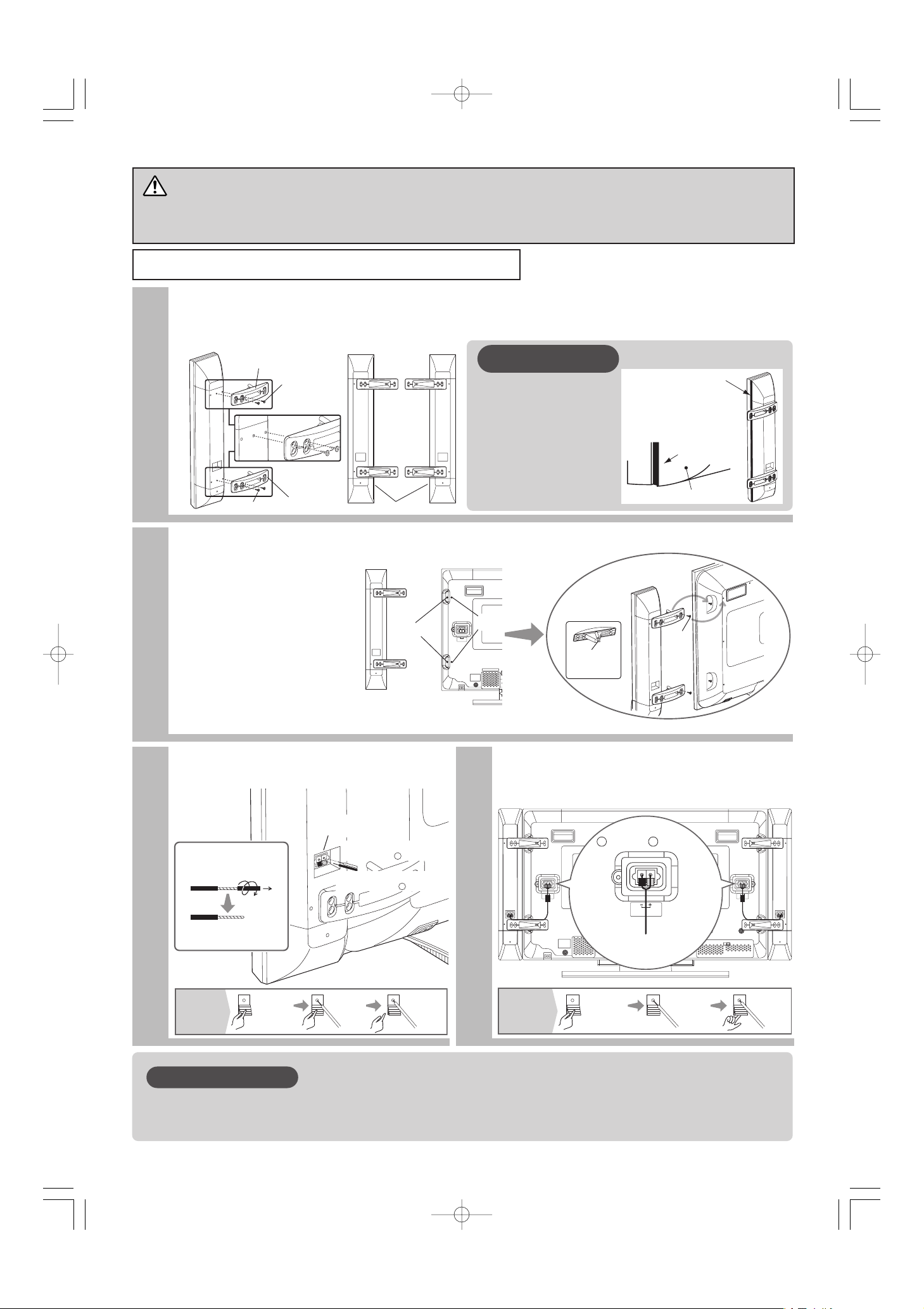
Veuillez bien insérer les câbles des haut-parleurs.
Veuillez verrouiller sans faute le levier du connecteur de branchement.
PRECAUTIONS
ATTENTION
Veuillez brancher ou débrancher les câbles des haut-parleurs après avoir mis sans faute l’écran
hors tension (dans l’état de veille ou avec la lampe d’alimentation éteinte ou allumée en rouge).
Fixer les haut-parleurs sur l’écran.
1
2
Fixer les dispositifs de support des haut-parleurs.
Mettre en place les vis de fixation afin que le sens des supports des haut-parleurs soit correct et dans une
position où l’on puisse lire correctement (R), (L).
L
R
Vis x 2
Vis x 2
Support de haut-parleur
Support de
haut-parleur
(D)
Dans le cas de (D).
(G)
Coussin
SPEAKER TERMINAL
(8Ω8W)
Vis
desserrées
Côté arrière de l’écran
Accrocher cette
partie sur la vis
desserrée
Support de haut-parleur
vu de l’autre côté
Retirer
les vis
Retirer
les vis
スピーカー端子
(6Ω12W)
Côté droit
Retirer les deux vis de chaque côté de l’écran
comme indiqué sur la figure et les conserver
soigneusement pour le remontage. Desserrer les
deux vis de chaque côté de l’écran comme indiqué
sur la figure de telle sorte que les supports de hautparleur puisse être monté sur eux en coulissant.
Insérer les vis desserrées dans les trous des
supports de haut-parleurs qui sont fixés au système
de haut-parleur et faire glisser les vis vers les bas.
Ensuite, utiliser les vis qui ont été enlevées pour
fixer les supports de haut-parleurs dans les trous de
montage situés sur l’écran. Resserrer les quatre vis
pour bien immobiliser le dispositif.
Fixer les haut-parleurs sur l’écran.
3
4
Installer les câble de branchement
des haut-parleurs
Brancher le câble couleur
cuivre au côté
Brancher le câble couleur
argentée au côté
Te rminaux des
haut-parleurs
+
-
Brancher les câbles de connexion
des haut-parleurs à l’écran à plasma
A propos des coussins
Il existe un espace entre le hautparleur et l’unité principale (écran
plasma). Pour les personnes que
cet espace préoccupe, appliquer
les coussins fournis avec
l’équipement sur le côté des hautparleurs.
Appliquer les
coussins sur le côté
des coussins.
Coussins
En faisant
correspondre avec la
face avant du boîtier
arrière, appliquer les
coussins.
Boîtier arrière
Remarque
0042型スピーカー統合-五校03.9.93:39PMページ4
Préparation des
extrémités des câbles
Tirer tout en tordant
Veuillez préparer les câbles de hautparleur fournis avec l’équipement
-
Noir Rouge
スピーカー端子
(6Ω12W)
スピーカー端 子
Brancher le
câble de couleur
argentée
(6Ω12W )
( )( )
+
Brancher le
câble de couleur
cuivre
スピーカー端子
(6Ω12W)
Comment connecter
les câbles des haut parleurs
(côté haut-parleur)
Appuyer vers
le bas sur le
levier avec votre
doigt
Insérer le
câble
Retirer
votre doigt
Comment connecter
les câbles des haut parleurs
(côté écran)
Appuyer
vers le bas
sur le levier
Insérer le
câble
Remonter
le levier
Page 61
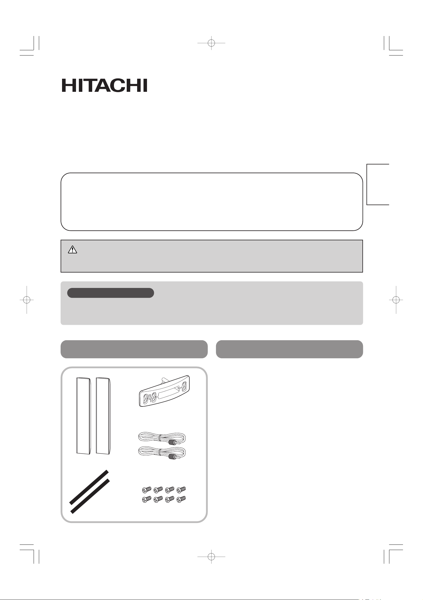
DEUTSCH
Lautsprecherboxen für Hitachi Plasma-Displaymonitor
Geeignetes Modell: 42PD5000*,42PMA500*,42HDM70,CMP421*
Modell
CMPAS14/CMPAS14S
Bedienungsanleitung
Herzlichen Glückwunsch zum Kauf des HITACHI Plasmadisplay-Lautsprechersystems.
BITTE LESEN SIE DIE ANWEISUNGEN DIESER BEDIENUNGSANLEITUNG
SORGFÄLTIG DURCH.
BEWAHREN SIE DIESE ANLEITUNG ZUM ZUKÜNFTIGEN NACHSCHLAGEN AUF.
VORSICHT
TRAGEN SIE DEN MONITOR NICHT, INDEM SIE DIE LAUTSPRECHERBOXEN GREIFEN.
Bitte die Lautsprecherboxen vorsichtig behandeln. Da die Vorderseite der Lautsprecherboxen
empfindlich ist, NICHT stark andrücken oder anstoßen.
Vorsicht erforderlich
Produktkomponenten Technische Daten
Lautsprecher (x2)
Lautsprecherkabel mit Ader (x2)
Polster (2)
Lautsprecherhalterung (x4)
Befestigungsschraube (x8)
Typ .................................
2 Wege 3 Lautsprecher.
Bassreflex
Tieftöner.........................
80 mm Konustyp x je 2
Hochtöner.......................25 mm Kalottentyp
Impedanz .......................6 Ω
Max. Eingangleistung.....50 W
Effektiv-Eingangsleistung
...20 W
Außenabmessungen......Je 101,5 (B) x 635,5
(H) x 90,5 (T) mm
Gewicht ..........................Je 2,1 kg
Änderungen bei technischen Daten und Design
im Sinne der Produktverbesserung bleiben
vorbehalten.
0042型スピーカー統合-五校03.9.93:39PMページ5
Page 62

Setzen Sie die Lautsprecherkabel fest ein.
Sperren Sie den Anschlussterminalhebel sicher.
Vorsicht erforderlich
Vorsicht
Stellen Sie sicher, dass der Monitor ausgeschaltet ist (mit Standby/Empfang-Lämpchen
erloschen oder rot), bevor Sie die Lautsprecherkabel anschließen oder abtrennen.
Bringen Sie die Lautsprecherbügel am Monitor an.
1
2
Bringen Sie die Lautsprecherbügel an den Lautsprecherboxen an.
Bringen Sie die Schrauben in einer Position an, die es erlaubt, die Lautsprecherhalter-Ausrichtmarkierungen (R), (L) zu sehen.
L
R
Schraube X 2
Schraube X 2
Lautsprecherhalterung
Lautsprecherhalterung
(R)
Bei (R)
(L)
Polster
SPEAKER TERMINAL
(8Ω8W)
Schrauben
lösen
Monitor-Rückseite
Lautsprecherhalterung
auf der anderen Seite
gezeigt
Haken Sie diese
Sektion auf die
gelöste Schraube
Schrauben
entfernen
Schrauben
entfernen
スピーカー端子
(6Ω12W)
Rechte Seite
Entfernen Sie die beiden Schrauben an jeder Seite des
Monitors wie gezeigt und bewahren Sie sie zur
Wiederanbringung auf. Lösen Sie die beiden Schrauben
an jeder Seite des Monitors wie gezeigt, so dass die
Lautsprecherhalterungen darauf gleiten können. Setzen
Sie die gelösten Schrauben in die Einsetzlöcher an den
Lautsprecherhalterungen am Lautsprechersystem ein,
und schieben Sie die Schrauben nach unten.
Dann verwenden Sie die vorher entfernten Schrauben
zum Befestigen der Lautsprecherhalterungen an den
Montagelöchern des Monitors. Ziehen Sie die vier
Schrauben zur Befestigung an.
Bringen Sie die Lautsprecherbügel am Monitor an.
3
4
Bringen Sie die Verbindungskabel
an der Lautsprecherbox an.
Schließen Sie den kupferfarbigen
Draht an der Seite an.
Schließen Sie den silberfarbigen
Draht an der Seite an.
Anschlüsse für
Lautsprecher
+
-
Bringen Sie die Lautsprecherverbindungskabel
am Monitor an.
Anschließen der
Lautsprecherkabel
(Monitor-Seite)
Drücken Sie
den Hebel
ein
Setzen Sie
den Draht ein
Heben Sie
den Hebel
an
Verwendung von Polstern
In manchen Fällen kann ein
Abstand zwischen Hauptgerät und
Lautsprecher auftreten. Sie können
wenn gewünscht die mitgelieferten
Polster an der Seite der
Lautsprecherbox anbringen, um
diesen Abstand zu beseitigen.
Polster
Rückwand
Bringen Sie die
Polster an den
Seiten der
Lautsprecher an,
die zum Hauptgerät
weisen.
Fluchten Sie die
Polster zur Vorderseite
der Rückwand und
bringen sie an.
Hinweis
0042型スピーカー統合-五校03.9.93:39PMページ6
Behandlung der Drahtenden
Beim Drehen abziehen
Bitte bereiten Sie die mitgelieferten
Lautsprecherkabel vor.
-
Schwarz
スピーカー端子
(6Ω12W)
Schließen Sie den
silberfarbigen
Draht an
+
Rot
スピーカー端 子
(6Ω12W )
Schließen Sie den
kupferfarbigen
( )( )
Draht an
スピーカー端子
(6Ω12W)
Anschließen der
Lautsprecherkabel
(Lautsprecherseite)
Drücken Sie
den Hebel mit
dem Finger ein
Setzen Sie
den Draht ein.
Nehmen Sie
den Finger
weg
Page 63

ITALIANO
Sistemi Audio per Schermo al Plasma Hitachi.
Utilizzabile con i seguenti modelli:
42PD5000*,42PMA500*,42HDM70,CMP421*
Modello
CMPAS14/CMPAS14S
Manuale Utente
Grazie per l’acquisto del sistema audio Hitachi per schermo al plasma.
Leggere attentamente le istruzioni contenute in questo manuale utente.
Conservare il manuale utente per riferimenti futuri.
Attenzione
Non maneggiare lo schermo attraverso il sistema audio.
Manneggiare con cautela il sistema audio. A causa della fragilita’ della parte anteriore del
sistema audio, fare attenzione a non sottoporre a forte pressione o ad impatti.
Fare attenzione
Componenti del Prodotto Caratteristiche
Altoparlanti (x2)
Cavo con anima per
altoparlante. (x2)
Ammortizzatori
(2)
Supporto per
altoparlante (x4)
Viti di montaggio (x8)
Tipo ................................2 vie 3 casse. Basso
con Reflex
Woofer............................80mm tipo a cono x
2/ciascuno
Tweeter ..........................25 mm tipo a cupola
Impedenza .....................6 Ω
Potenza massima d’ingresso
...50 W
Potenza d’ingresso RMS
....20 W
Dimensioni Esterne........
101,5 (Spessore) x
635,5 (Altezza) x 90,5
(Diametro) mm/ciascuno
Peso...............................2,1 kg/ciascuno
Le caratteristiche ed il design sono soggetti a
possibili modificazioni senza avviso, dovuto a
miglioramenti.
0042型スピーカー統合-五校03.9.93:39PMページ7
Page 64

Assicurarsi di inserire in modo sicuro i cavi degli altoparlanti.
Chiudere in modo sicuro il livello connesione terminali
Fare attenzione
Attenzione
Assicurarsi dello spegnimento dello schermo (con la luce di standby/ricezione, spenta o rossa)
prima di connettere o sconnettere i cavi audio.
Fissare il sistema audio allo schermo
1
2
Fissare i supporti degli altorparlanti al sistema audio.
Fissare le viti in una posizione che permetta di leggere l’orientamento del supporto degli altoparlanti (R), (L).
L
R
Lato posteriore dello schermo
SPEAKER TERMINAL
(8Ω8W)
Viti
allentate
スピーカー端子
(6Ω12W)
Lato destro
Agganciare
questo lato alle
viti allentate
Il supporto degli
autoparlanti mostrato
sull’altro lato
Rimuovere
le viti
Rimuovere
le viti
Togliere le due viti su ogni lato del monitor
come illustrato e tenerle per il riassemblamento. Allentare le due viti su
ogni lato del monitor come illustrato in
modo da potervici far slittare sopra i
sostegni delle casse. Inserire le viti allentate
nei fori dei sostegni delle casse, che sono
attaccati al corpo delle casse, e far slittare
le viti verso il basso. In seguito, usare le viti
rimosse precedentemente per stringere i
sostegni negli appositi fori nel monitor.
Stringere le quattro viti per fissare.
Fissare il sistema audio allo schermo
3
4
Collegare i cavi di connessione al
sistema audio.
Collegare il cavo color
rame al polo
Collegare il cavo color
argento al polo
Te rminali dell’altoparlante
+
-
Collegare i cavi di connessione
audio allo schermo
スピーカー端子
(6Ω12W)
スピーカー端子
(6Ω12W)
( )( )
スピーカー端 子
(6Ω12W )
Nero Rosso
+
-
Connettere il
cavo color
rame
Connettere il
cavo color
argento
Come collegare
i cavi degli
altoparlanti
(lato dello schermo)
Premere in
basso la leva
Alzare
la leva
Inserire il
cavo
Uso degli ammortizzatori
In alcuni casi, potrebbe crearsi
dello spazio tra l'unita' principale e
gli altoparlanti.
Se lo si desidera, e' possibile
eliminarlo fissando
sul lato del sistema audio gli
ammortizzatori forniti.
Nota
0042型スピーカー統合-五校03.9.93:39PMページ8
In caso di (R)
Supporto altoparlante
Viti x 2
(R)
(L)
Fissare gli ammortizzatori
ai lati degli altoparlanti
mantenendoli rivolti
verso l'unita' principale.
Ammortizzatore
Allineare gli
ammortizzatori sulla
parte posteriore del
contenitore e applicarli.
Parte posteriore
del supporto
Viti x 2
Supporto
altoparlante
Ammortizzatore
Tr attare gli estremi dei cavi
Tirare durante la torsione.
Preparare i cavi forniti
Come collegare
i cavi di
connessione
(lato altoparlanti)
Premere in
basso la leva
con le dita
Inserire
il cavo
Rimuovere
il dito
Page 65

ESPAÑOL
Sistema de altavoces para el Monitor Plasma de Hitachi
Modelo Aplicable: 42PD5000*,42PMA500*,42HDM70,CMP421*
Modelo
CMPAS14/CMPAS14S
Manual del Usuario
Muchas gracias por la adquisición del Sistema de Altavoces para el Monitor Plasma de Hitachi.
LEA CUIDADOSAMENTE INSTRUCCIONES CONTENIDAS EN ESTE MANUAL DEL
USUARIO. GUARDE ESTE MANUAL PARA LAS FUTURAS REFERENCIAS.
PRECAUCION
NO MANIPULE EL MONITOR SOSTENIENDO POR EL SISTEMA DE ALTAVOCES.
Tenga sumo cuidado en el tratamiento de los sistemas de altavoz. Como la delantera de los
sistemas de altavoz es frágil, cuídese de NO empujarla fuertemente ni golpearla.
NOTA
Componentes del Producto
Especificaciones
Altavoces (x2)
Cable de altavoz con núcleo (x2)
Cojín (2)
Soporte de altavoz (x4)
Tornillo de montaje (x8)
Tipo ................................
3 altavoces bidireccionales.
Bass Reflex
Altavoz graves................Tipo cónico de 80mm
x 2/cada uno
Altavoz agudos...............Tipo cúpula 25 mm
Impedancia.....................6 Ω
Potencia de entrada máx.
....50 W
Potencia de entrada RMS
....20 W
Dimensiones externas....101,5 (Ancho) x 635,5
(Alto) x 90,5 (Fondo)
mm/cada uno
Peso...............................2,1 kg /cada uno
Las especificaciones y diseño están sujetos a
modificaciones sin previo aviso por fines de mejora.
0042型スピーカー統合-五校03.9.93:39PMページ9
Page 66

Asegúrese de insertar firmemente los cables de altavoz.
Asegúrese de bloquear firmemente la palanca de los terminales de conexión.
NOTA
ATENCION
La conexión/desconexión de los cables de altavoz debe realizarse siempre con el interruptor de alimentación del
monitor desconectado (en estado de espera/lámpara de recepción de imagen apagada o encendida en rojo).
Sujete el sistema de altavoces deslizándolo sobre los tornillos aflojados y reinstale los tornillos retirados.
1
2
Sujete los soportes de altavoz a los sistemas de altavoz.
Sujete los tornillos en una posición que permita leer las marcas de orientación de los soportes de altavoz (R), (L).
L
R
To rnillo de montaje
X 2
To rnillo de
montaje
X 2
Soporte de altavoz
Soporte de
altavoz
(R)
En caso de (R)
(L)
Cojín
SPEAKER TERMINAL
(8Ω8W)
スピーカー端子
(6Ω12W)
Afloje los
tornillos
Lado trasero del monitor
Quite los
tornillos
Lado derecho
Sujetador del altavoz
visto de abajo
Enganche esta
porción en el
tornillo aflojado
Quite los
tornillos
Quite los dos tornillo de cada costado del monitor
tal como se muestra y manténgalos para su
reinstalación. Afloje los dos tornillos de cada
costado del monitor tal como se muestra de
manera que los sujetadores de altavoz puedan
deslizarse sobre ellos. Inserte los tornillos
aflojados en los agujeros de enganche de los
sujetadores de altavoz que están sujetos al
sistema de altavoces, y deslice los tornillos hacia
abajo. Seguidamente, use los tornillos
previamente aflojados para sujetar los sujetadores
de altavoz en los agujeros de montaje del monitor.
Apriete firmemente los cuatro tornillos.
Sujete el sistema de altavoces deslizándolo sobre los tornillos aflojados y reinstale los tornillos retirados.
3
4
Conexión de los cables de
conexión al sistema de altavoces
Conecte el cable de color
de cobre al lado
Conecte el cable de color
de plata al lado
Te rminales de
altavoz
+
-
Sujete los cables de conexión de
altavoz al monitor.
Modo de conectar
los cables de
altavoz
(Lado del monitor)
Empuje hacia
abajo la palanca
Levante la
palanca
Inserte el
cable
Sobre el cojín.
Hay posibilidad de que
se produzca una
pequeña separación
entre la unidad principal
y el sistema de
altavoces.
Cojín
Caja trasera
Esta separación puede
eliminarse pegando el
cojín suministrado a la
superficie lateral del
sistema de altavoz.
Pegue el cojín
alineando la
superficie delantera
de la caja trasera.
Aviso
0042型スピーカー統合-五校03.9.93:39PMページ10
Tr atamiento de los extremos del cable
Quítelos mientras los dobla
Prepare los cables de
altavoz suministrados.
-
Negro Rojo
スピーカー端子
(6Ω12W)
Conecte el
cable de color
de plata
+
スピーカー端 子
(6Ω12W )
Conecte el
cable de color
( )( )
de cobre
スピーカー端子
(6Ω12W)
Modo de conectar
los cables de
altavoz
(Lado del altavoz)
Empuje hacia
abajo la palanca
con su dedo.
Inserte el
cable.
Quite su
dedo.
Page 67

SVENSKA
Högtalarsystem för Hitachi Plasmaskärmar.
Passar till följande modeller: 42PD5000*,42PMA500*,42HDM70,CMP421*
Modell
CMPAS14/CMPAS14S
Användarmanual
Tack för att du köpte detta högtalarsystem för Hitachi Plasmaskärmar.
LÄS INSTRUKTIONERNA I DENNA MANUAL NOGGRANT.
SPARA DENNA MANUAL FÖR FRAMTIDA BEHOV.
FÖRSIKTIGHET
HANDSKAS INTE MED SKÄRMEN GENOM ATT HÅLLA I HÖGTALARSYSTEMET.
Var försiktig vid handskande med högtalarsystemet. Då framsidan på högtalarsystemet är
ömtålig utsätt INTE denna för tryck eller våld.
Var god beakta följande
Innehållsförteckning Specifikationer
Högtalare (x2)
Högtalarkabel med kärna (x2)
Vibrationsdämpare
(x2)
Högtalarhållare (x4)
Monteringsskruvar (x8)
Typ .................................2 vägs 3 högtalare.
Basreflex
Bashögtalare..................80 mm typ kärna x 2 /
enhet
Diskanthögtalare ............25 mm kupol typ
Impedans .......................6 Ω
Max. ineffekt...................50 W
RMS ineffekt...................20 W
Utvändiga dimensioner
....101,5 (B) x 635,5 (H)
x 90,5 (D) mm/enhet
Vikt .................................2,1 kg/enhet
Specifikationer och design kan komma att
ändras utan förvarning på grund av
förbättringar.
0042型スピーカー統合-五校03.9.93:39PMページ11
Page 68

Se till att kablarna förs in ordentligt.
Se till att handtagen på anslutningskontakterna är ordentligt låsta.
Var god beakta följande
Varning
Högtalarkablarna får endast anslutas/kopplas ur då strömmen till skärmen är av
(Vänteläge/mottagningslampan är släckt eller lyser rött)
Montering av högtalarsystemet på skärmen.
1
2
Anslut högtalarhållarna till högtalarsystemet.
Vänd högtalarhållarna så att (R), (L) kan läsas korrekt och fäst med skruvarna.
LRL
R
skruv x 2
skruv x 2
Högtalarhållare
Högtalarhållare
(R)
I fallet (R)
(L)
vibrationsdämpare
SPEAKER TERMINAL
(8Ω8W)
スピーカー端子
(6Ω12W)
Lossa
skruvarna
Skärmens baksida
Haka denna
sektion på de
lossade skruvarna
Högtalarhållarna
sedda underifrån
Ta bort
skruvarna
Ta bort
skruvarna
Höger sida (R)
Ta bort de två skruvarna på var sida om
skärmen som bilden visar och spar dem för
senare bruk. Lossa de två skruvarna på var
sida om skärmen som bilden visar så att
högtalarhållarna kan glida ner på dem. Passa
in de lossade skruvarna i anslutningshålen på
högtalarhållarna som är monterade på
högtalarsystemet och skjut ner högtalarna.
Skruva i de tidigare borttagna skruvarna och
fixera högtalarhållarna på skärmen. Dra åt
samtliga fyra skruvar.
Montering av högtalarsystemet på skärmen.
3
4
Anslutning av högtalarkablar
Anslut den kopparfärgade
kabeln till sidan
Anslut den silverfärgade
kabeln till sidan
Ände mot högtalare
+
-
Anslutning av högtalarkablarna till
skärmen
Om vibrationsdämparna
Det kan uppstå glapp mellan
skärmen och högtalarna. Använd
de bifogade vibrationsdämparna
för att fylla ut detta glapp genom
att montera dessa på
högtalarsystemet innan montage
på skärmen.
Information
0042型スピーカー統合-五校03.9.93:39PMページ12
Förbered kablarnas ändar
Förbered de bifogade
högtalarkablarna
Vrid och drag loss
Vibrationsdämpare
Fäst vibrationsdämparna
på sidan av högtalarna
vända mot huvudenheten.
Passa in och fäst
vibrationsdämparna
på framsidan
av bakstycket.
Bakstycke
-
Svart Röd
スピーカー端子
(6Ω12W)
Anslut den
silverfärgade
kabeln
+
スピーカー端 子
(6Ω12W )
Anslut den
kopparfärgade
( )( )
kabeln
スピーカー端子
(6Ω12W)
Hur man
ansluter
högtalarkablarna
(Högtalare)
Tr yck ner
handtaget
med ett finger
För in
kabeln
Ta bort
fingret
Hur man
ansluter
högtalarkablarna
(Skärm)
Tr yck ner
handtaget
För in
kabeln
För upp
handtaget
Page 69

NORSK
Høytalersystemer for Hitachi Plasma skjermmonitor.
Brukermodell: 42PD5000*,42PMA500*,42HDM70,CMP421*
Modell
CMPAS14/CMPAS14S
Brukermanual
Takk for at du kjøpte Hitachi Plasma skjermmonitor
LES INSTRUKSJONENE I DENNE BRUKERVEILEDNINGEN NØYE.
OPPBEVAR DENNE BRUKERVEILEDNINGEN FOR SENERE REFERANSE.
VARSEL
Ikke behandl monitoren ved å holde på høytalersystemene.
Vær forsiktig med å håndtere høytalersystemene. Da høytalersystemenes forside er lett
skadelig, vennligst ikke behandl på en uaktsomlig måte.
Streng aktsomhet
Produktskomponenter Tekniske Data
Høytalere (x2)
Høytalerkabel med kjerne (x2)
Puten (2 stk)
Høytalerholder (x4)
Monteringsskrue (x8)
Type ...............................2 –veis 3 høytalere.
Bassrefleks
Woofer............................80mm konisk type x
2/hver
Tweeter ..........................25 mm dome-type
Impedans .......................6 Ω
Maks. utgangseffekt.......50 watt
RMS inngangseffekt.......20 watt
Utvendige dimensjoner
......101,5 x 635,5 x 90,5
mm (B x H x D) hver
Vekt................................2,1 kg hver
Tekniske data og utforming kan bli endret uten
varsel pga. utbedringer.
0042型スピーカー統合-五校03.9.93:39PMページ13
Page 70

Stikk inn høytalerkabelen med sikkerhet
Steng koblingsspaken med sikkerhet.
Streng aktsomhet
VARSEL
Høytalerkabelen skal være slått av ved innkobling / utkobling (Ved Standby / mottakerlampen
ikke er på eller når den røde lampen blinker).
Monter høytalersystemene til monitoren.
1
2
Monter høytalerledningene til høytalersystemene.
Skruene skal monteres når (R) og (L) for høytalerholderens retning vises riktig.
L
R
SPEAKER TERMINAL
(8Ω8W)
スピーカー端子
(6Ω12W)
Løsne
skruene
Baksiden av monitoren
Monter denne
delen på den
løsnede skruen
Høytalerholderen
som vist fra den andre siden
Fjern
skruene
Fjern
skruene
Stram fast skruene.
Skru ut de to skruene fra begge sider av
skjermen som vist og oppbevar dem for
påmonteringen.
Løsne de to skruene fra begge sider av
skjermen som vist slik at høytalerholderene kan
skyves inn.
Skyv inn de to løsnede skruene inn i
festehullene på høytalerholderene som er
festet til høytalersystemet og skyv skruene ned.
Bruk deretter de tidligere fjernede skruene til å
feste høytalerholderene til skjermen.
Stram fast de fire skruene.
Monter høytalersystemene til monitoren.
3
4
Monter koblingskabelen til
høytalersystemet
Koble den kobberfarvede
tråden til side
Koble den sølvfarvede
wiren til side
Høytalerterminaler
+
-
Tr ykk ned
spaken med
fingeren din
Fjern
fingeren din
Putt inn
wiren
Hvordan koble inn
høytalerkablene
(Høytalersiden)
Monter høytalerens koblingskabel til
monitoren
Hvordan koble
høytalerkablene
(Monitorsiden)
Tr ykk ned
spaken
Trekk opp
spaken
Stikk inn
tråden
Om puten
En liten åpning vil oppstå
ved enkelte tilfeller
mellom legemet og
høytaleren.
Ved gjentetning av
åpningen kan du montere
puten på legemets side.
Melding
0042型スピーカー統合-五校03.9.93:39PMページ14
For (H)
Høytalerholder
skrue x 2
(H)
(V)
Tilpass den til
bakhusets forside.
Puten
Behandle trådendene
Trekk ut ved vridning
Vennligst gjør klar de
tilbehørende høytalerkablene.
skrue x 2
Høytalerholder
Puten
Sett putene i
kant med
bakseksjonens
front og fest dem.
Bakseksjon
Sort Rød
+-
( )( )
スピーカー端子
(6Ω12W)
スピーカー端 子
(6Ω12W )
Koble den
sølvfarvede
tråden
Koble den
kobberfarvede
( )( )
tråden
スピーカー端子
(6Ω12W)
Page 71

簡体中文
0042型スピーカー統合-五校03.9.93:39PMページ15
Page 72

0042型スピーカー統合-五校03.9.93:39PMページ16
Page 73

繁體中文
0042型スピーカー統合-五校03.9.93:39PMページ17
Page 74

0042型スピーカー統合-五校03.9.93:39PMページ18
Page 75

日本語
日立42V型プラズマディスプレイ専用スピーカーシステム
形名
CMPAS14/CMPAS14S 取扱説明書
このたびは日立プラズマディスプレイ専用スピーカーシステムをお買い上げいただき、まことにあ
りがとうございました。
正しくお使いいただくために、この「取扱説明書」をよくお読みください。
お読みになったあとは、必ず保管してください。
◎ このプラズマディスプレイスピーカーシステムは、CMP421* 専用です。
注意
モニターを移動するときは、スピーカーシステムを持たないでください。
スピーカ−システム前面のグリル部を強く押したり、グリル部に衝撃を与えると、スピーカー破損の
恐れがありますので、慎重にお取り扱いください。
お守りください
部品構成表 仕様
スピーカー(2個)
スピーカー接続ケーブル
(コア付)(2本)
クッション
(2本)
スピーカーホルダー(4個)
取付けネジ(8本)
タイプ ..........................2ウェイ3スピーカ
バスレフ型
ウファー.......................80mmコーン型×2個
(左右それぞれ)
ツィータ.......................25mmドーム型
定格インピーダンス
....6Ω
定格入力.......................20W JEITA
最大入力.......................50W 音楽信号ピーク
外形寸法.......................101.5(幅)×635.5
(高さ)×90.5(奥行き)
mm(左右それぞれ)
質量 ..............................2.1kg(左右それぞれ)
改良の為、仕様及びデザインを予告無く変更す
ることがありますのでご了承ください。
0042型スピーカー統合-五校03.9.93:39PMページ19
Page 76

スピーカーケーブルは確実に挿入してください。
接続端子レバーは確実にロックしてください。
お守りください
注意
スピーカーケーブルは、必ずモニターの電源を切った状態(スタンバイ/受像ランプが消えているかま
たは、赤に点灯している状態)で接続/取り外しをしてください。
モニターにスピーカーシステムを取り付ける
1
2
スピーカーシステムにスピーカーホルダーを付ける
スピーカーホルダーの向きは(R)、(L)の表示が正しく読める位置にネジを取り付けます。
L
R
ネジ×2
ネジ×2
スピーカーホルダー
スピーカーホルダー
(R)
(R)の場合
(L)
クッション
SPEAKER TERMINAL
(8Ω8W)
スピーカー端子
(6Ω12W)
ネジを
緩める
モニター後面
この部分を
緩めたネジに
引っかける
スピーカーホルダー
を下から見た図
外した
ネジ
ネジを
はずす
スピーカーシステムに取
り付けた、スピーカーホ
ルダーの引っ掛け穴に緩
めたネジを挿入し下にず
らす。
次に、スピーカーホルダ
ーを本体側固定穴に取り
外したネジで固定する。
スピーカーシステムをモニターに取り付ける
3
4
スピーカーシステムに接続ケーブルを
取り付ける
○赤側に銅色線を接続
+
○黒側に銀色線を接続
−
スピーカーシステム
接続端子
よじりながら抜く
付属のスピーカー接続ケーブル
を図のように加工してください。
先端処理のしかた
モニターにスピーカー接続ケーブルを取り
付ける
クッションについて
本体とスピーカーの間に
すき間が発生する場合が
あります。すき間が気に
なる方は、付属のクッシ
ョンをスピーカーシステ
ムの側面に貼り付けてく
ださい。
お知らせ
QR59021
0042型スピーカー統合-五校03.9.93:39PMページ20
クッション
クッションは
スピーカーシステムの
本体側面に貼り付けて
ください。
バックケース
の前側に合わせ
て貼ってください。
バックケース
スピーカー
接続ケーブルの
接続方法
(スピーカー側)
レバーを
指で
押したまま
接続ケーブル
を挿入する
○黒−○赤
指を離す
スピーカー
接続ケーブルの
接続方法
(モニター側)
スピーカー端子
(6Ω12W)
スピーカー端 子
銀色線
を接続
レバーを
押し下げる
+
(6Ω12W )
銅色線
( )( )
を接続
接続ケーブル
を挿入する
スピーカー端子
(6Ω12W)
レバーを
起こす
 Loading...