

Hitachi 42HDT52, 42HDT52A User Manual

PLASMA TELEVISION
Operating Guide for
42HDT52, 42HDT52A and
55HDT52
IMPORTANT SAFETY INSTRUCTIONS....................................................................................... 2-3
FIRST TIME USE ....................................................................................................................... 4-22
THE REMOTE CONTROL........................................................................................................ 23-41
ON-SCREEN DISPLAY............................................................................................................ 42-90
USEFUL INFORMATION.......................................................................................................... 91-98
END USER LICENSE AGREEMENT FOR HITACHI DTV SOFTWARE...........................................99
APPENDIXES ........................................................................................................................100-101
INDEX...........................................................................................................................................102
As an Energy Star®Partner,
Hitachi, Ltd. has determined
that this product meets the
Energy Star®guidelines for
energy efficiency.
Updated 04.25.06
2
Important Safety Instructions
SAFETY POINTS YOU SHOULD KNOW ABOUT
YOUR HITACHI PLASMA TELEVISION
Our reputation has been built on the quality,
performance, and ease of service of HITACHI plasma
televisions.
Safety is also foremost in our minds in the design of
these units. To help you operate these products
properly, this section illustrates safety tips which will be
of benefit to you. Please read it carefully and apply the
knowledge you obtain from it to the proper operation of
your HITACHI plasma television.
Please fill out your warranty card and mail it to
HITACHI. This will enable HITACHI to notify you
promptly in the improbable event that a safety problem
should be discovered in your product model.
Follow all warnings and instructions marked on
this plasma television.
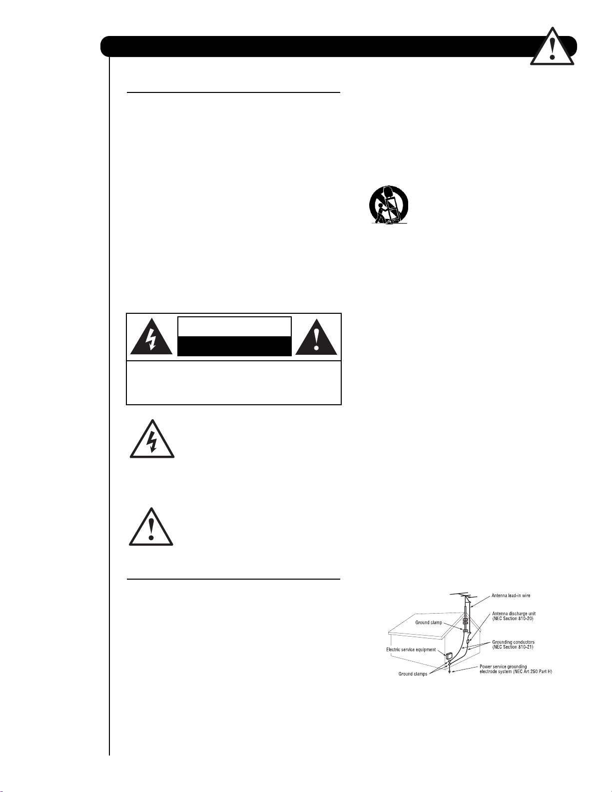
The lightning flash with arrowhead symbol,
within an equilateral triangle, is intended to
alert the user to the presence of
uninsulated “dangerous voltage” within the
product’s enclosure that may be of a sufficient
magnitude to constitute a risk of electric shock to a
person.
The exclamation point within an equilateral
triangle, is intended to alert the user to the
presence of important operating and
maintenance (servicing) instructions in the
literature accompanying the appliance.
READ BEFORE OPERATING EQUIPMENT
Follow all warnings and instructions marked on this
plasma television.
1. Read these instructions.
2. Keep these instructions.
3. Heed all warnings.
4. Follow all instructions.
5. Do not use this apparatus near water.
6. Clean only with a dry cloth.
7. Do not block any ventilation openings. Install in
accordance with the manufacturer’s instructions.
8. Do not install near any heat sources such as
radiators, heat registers, stoves, or other apparatus
(including amplifiers) that produce heat.
9. Do not defeat the safety purpose of the polarized or
grounding-type plug. A polarized plug has two
blades with one wider than the other. A grounding
type plug has two blades and a third grounding
prong. The wide blade or the third prong are
provided for your safety. If the provided plug does
not fit into your outlet, consult an electrician for
replacement of the obsolete outlet.
10. Protect the power cord from being walked on or
pinched particularly at plugs, convenience
receptacles, and the point where they exit from the
apparatus.
11. Only use the attachments/accessories specified by
the manufacturer.
12. Use only with the cart, stand, tripod,
bracket, or table specified by the
manufacturer, or sold with the
apparatus. When a cart is used, use
caution when moving the cart/apparatus
combination to avoid injury from tip-over.
13. Unplug this apparatus during lightning storms or
when unused for long periods of time.
14. Refer all servicing to qualified service personnel.
Servicing is required when the apparatus has been
damaged in any way, such as power-supply cord or
plug is damaged, liquid has been spilled or objects
have fallen into apparatus, the apparatus has been
exposed to rain or moisture, does not operate
normally, or has been dropped.
15. Televisions are designed to comply with the
recommended safety standards for tilt and stability.
Do not apply excessive pulling force to the front, or
top, of the cabinet which could cause the product
to overturn resulting in product damage and/or
personal injury.
16. Follow instructions for wall, shelf or ceiling
mounting as recommended by the manufacturer.
17. An outdoor antenna should not be located in the
vicinity of overhead power lines or other electrical
circuits.
18. If an outside antenna is connected to the receiver
be sure the antenna system is grounded so as to
provide some protection against voltage surges and
built up static charges. Section 810 of the National
Electric Code, ANSI/NFPA No. 70-1984, provides
information with respect to proper grounding for the
mast and supporting structure, grounding of the
lead-in wire to an antenna discharge unit, size of
grounding connectors, location of antennadischarge unit, connection to grounding electrodes
and requirements for the grounding electrode.
Note to the CATV system installer: This reminder is
provided to call the CATV system installer’s attention to
Article 820-44 of the NEC that provides guidelines for
proper grounding and, in particular, specifies that the
cable ground shall be connected to the grounding
system of the building, as close to the point of cable
entry as practical.
CAUTION: TO REDUCE THE RISK OF ELECTRIC SHOCK,
DO NOT REMOVE COVER (OR BACK).
NO USER SERVICEABLE PARTS INSIDE.
REFER SERVICING TO QUALIFIED SERVICE PERSONNEL.
CAUTION
RISK OF ELECTRIC SHOCK
DO NOT OPEN
NEC National Electric Code
3
Important Safety Instructions
Power source
This plasma television is designed to operate on 120
volts 60 Hz, AC current. Insert the power cord into a
120 volt 60 Hz outlet.
To prevent electric shock, do not use the plasma
television’s (polarized) plug with an extension cord,
receptacle, or other outlet unless the blades and
ground terminal can be fully inserted to prevent blade
exposure.
Never connect the plasma television to 50 Hz, direct
current, or anything other than the specified voltage.
Caution
Never remove the back cover of the
plasma television as this can expose you
to very high voltages and other hazards. If
the television does not operate properly,
unplug the plasma television and call your authorized
dealer or service center.
Caution
Adjust only those controls that are covered in the
instructions, as improper changes or modifications not
expressly approved by HITACHI could void the user’s
warranty.
Warning
• To reduce the risk of fire or electric shock, do not
expose this apparatus to rain or moisture.
• The plasma television should not be exposed to
dripping or splashing and objects filled with liquids,
such as vases, should not be placed on the
television.
Modifications
The FCC requires the user to be notified that any
changes or modifications made to this device that are
not expressly approved by Hitachi America, Ltd. Home
Electronics Division may void the user’s authority to
operate the equipment.
Note
This plasma television will display television closed
captioning, ( or ), in accordance with paragraph
15.119 and 15.122 of the FCC rules.
Public viewing of copyrighted material
Public viewing of programs broadcast by TV stations
and cable companies, as well as programs from other
sources, may require prior authorization from the
broadcaster or owner of the video program material.
This product incorporates copyright protection
technology that is protected by U.S. patents and other
intellectual property rights. Use of this copyright
protection technology must be authorized by
Macrovision Corporation, and is intended for home and
other limited consumer uses only unless otherwise
authorized by Macrovision. Reverse engineering or
disassembly is prohibited.
Note
This digital television is capable of receiving analog
basic, digital basic and digital premium cable television
programming by direct connection to a cable system
providing such programming. A CableCARD provided
by your cable operator is required to view encrypted
digital programming. Certain advanced and interactive
digital cable services such as video-on-demand, a cable
operator’s enhanced program guide and data-enhanced
television services may require the use of a set-top box.
For more information call your local cable company.
Note
• There are no user serviceable parts inside the
plasma television.
• Model and serial numbers are indicated on back side
of the plasma television.
Prevention of screen damages
Continuous on-screen displays such as video games,
stock market quotations, computer generated graphics,
and other fixed (non-moving) patterns can be
permanently imprinted onto your TV screen. Such
“SCREEN DAMAGES” constitute misuse and are NOT
COVERED by your HITACHI Factory Warranty.
Lead Notice
This product contains lead. Dispose of this product in
accordance with applicable environmental laws. For
product recycling and disposal information, contact
your local government agency or www.eRecylcle.org
(in California), the Electronic Industries Alliance at
www.eiae.org (in the US) or the Electronic Product
Stewardship Canada at www.epsc.ca (in Canada).
FOR MORE INFORMATION, CALL 1-800-HITACHI.
4
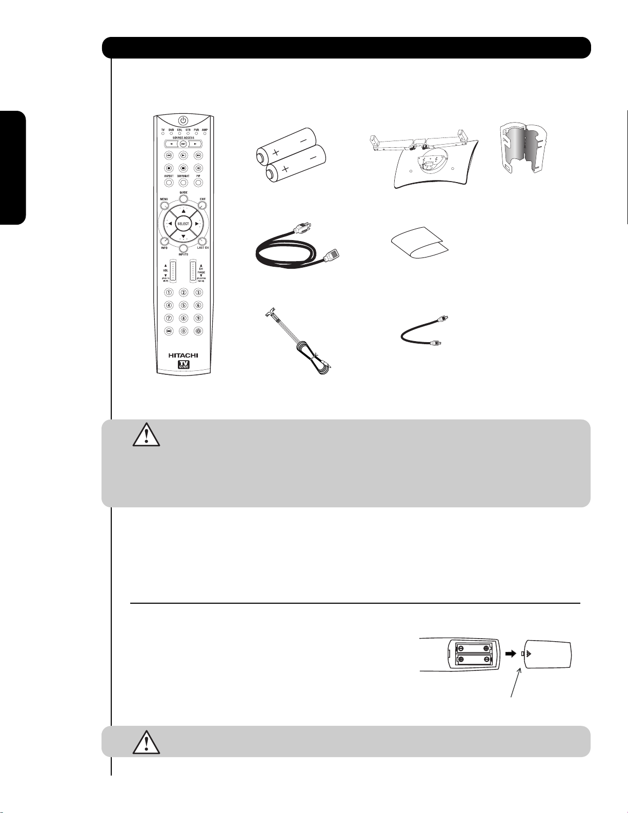
Accessories
First time use
Check to make sure you have the following accessories before disposing of the packing material.
CAUTION: 1. Ceiling mounting is not recommended. Mounting the panel on the ceiling does not
provide adequate ventilation for the electronics or proper support for the front glass
panel. This plasma television product is designed for a maximum tilting angle of 45
degrees from vertical.
2. This stand for use only with Hitachi 42HDT52 and 42HDT52A. use with other
apparatus is capable of resulting in instability causing possible injury. See
important marking located on bottom of stand.
Remote Control Unit CLU-3851WL Table Top Stand (P# QJ01831K).
(Part No. HL02065). Cleaning Cloth (P# MS00931).
Two “AA” size, 1.5V batteries (P# FQ00021). Power Swivel Cable (P# EW08431).
Power Cord (P# EV01841). 2 (2 pcs.) Ferrite Core (P#2169513).
Two IR Mouse cables (P# EY01641).
REMOTE CONTROL BATTERY INSTALLATION AND REPLACEMENT
1. Open the battery cover of the remote control by pushing down and
sliding the back cover off.
2. Insert two new “AA” size batteries for the remote control. When
replacing old batteries, push them towards the springs and lift them
out.
3. Match the batteries to the (+) and (-) marks in the battery
compartment.
4. Replace the cover.
CAUTION: Do not insert batteries with the ‘+’and ‘-’ polarities reversed as this may cause the
batteries to swell or rupture resulting in leakage.
Power Cord
Remote Control
Two “AA” size,
1.5V batteries
BOTTOM VIEW
(Remote Control)
Press down and slide back to remove.
2 IR Mouse Cables or
G-LINK Cables
Cleaning Cloth
Table Top
Stand (42”
models only)
Power Swivel Cable
(42” models only)
2 Ferrite Core
(see page 13)
For U.S. models:
For optional
accessories, please
access our web site at:
www.hitachi.us/tv
Note: Please visit our
website for optional
accessories for the
55” models.
/
5
First time use
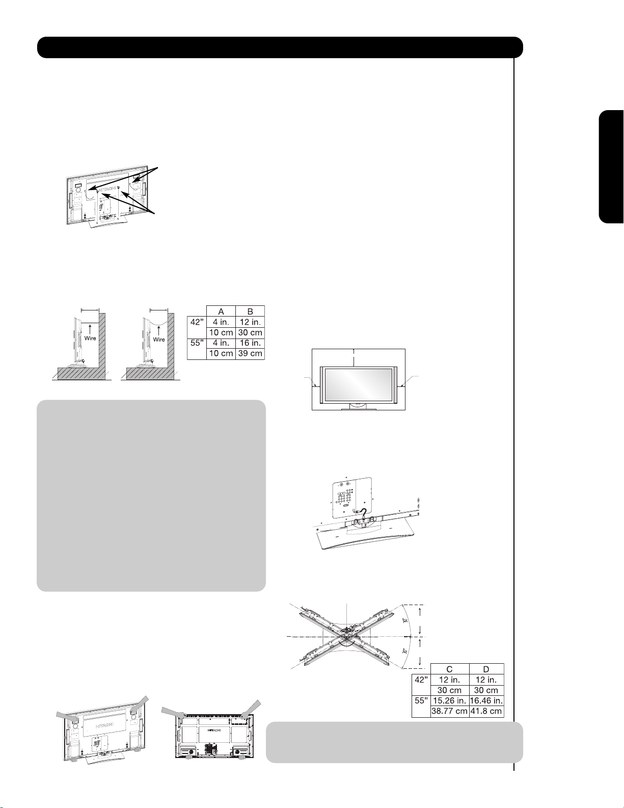
How To Set Up Your New Hitachi Plasma Television
Securing to a table-top
1. Using wood screws (two) fasten the set to the
clamping screw holes on the rear of the Plasma
Display stand as shown below.
2. Using commercially available wood screws, secure
the set firmly in position.
Securing to a Wall
1. Keep the Plasma television 4 inches away from the
wall except when mounted using the wall mount
bracket.
2. Secure the television to the wall as shown in fig. (a)
or (b).
NOTES: 1. Do not block the ventilation holes of
the Plasma Television. Blocking
the ventilation holes might cause fire
or defect.
2. In case of an abnormal symptom,
unplug the AC cord.
3. If you purchased the wall mount
bracket option, please ask for
professional installer. Do not install
by yourself.
4. If the Power Swivel feature will not be
used, the Plasma television should be
secured to the wall as shown in
fig. (a).
5. If the Power Swivel feature will be
used, the Plasma television should be
secured to the wall as shown in
fig. (b). The wires need to be long
enough to allow the television to turn
30˚ to the left and right.
Caution when moving the main unit
As this product is heavy, whenever it is moved, two
people are required to transport it safely. Whenever the
unit is moved it should be lifted forward using the top
and base on both sides of the Television for stability.
When moving the Television, lift the handles (42”
models), support the top frame (55” models) and the
bottom frame as shown below. Do not grab the
speakers or the back cover when lifting.
ANTENNA
Unless your Plasma Television is connected to a cable
TV system or to a centralized antenna system, a good
outdoor color TV antenna is recommended for best
performance. However, if you are located in an
exceptionally good signal area that is free from
interference and multiple image ghosts,
an indoor antenna may be sufficient.
LOCATION
Select an area where sunlight or bright indoor
illumination will not fall directly on the picture screen.
Also, be sure that the location selected allows a free
flow of air to and from the perforated back cover of the
set. In order to prevent an internal temperature
increase, maintain a space of 10 cm (4 inches) from the
sides/back of the Television, and 30 cm (12 inches)
from the top of the television to the wall. To avoid
cabinet warping, cabinet color changes, and increased
chance of set failure, do not place the TV where
temperatures can become excessively hot, for
example, in direct sunlight or near a heating appliance,
etc.
CONNECT POWER SWIVEL CABLE
Connect one end of cable (Arrow mark facing left) to
the swivel slot of the Plasma Rear Panel. Connect the
other end (Arrow mark facing front)to the swivel slot of
the Table Top Stand.
TURNING RADIUS
The maximum turning radius is 30˚ (left and right). Do
not place any objects on the path of the monitor when
using the power swivel feature.
NOTE: The Table Top Stand and Power Swivel cable
for model 55HDT52 are not included
(Optional).
To take measures to prevent the Plasma Television from tipping over and prevent possible injury
it is important to mount the unit in a stable and flat surface.
B
A
(a) Power Swivel
NOT USED
(b) Power Swivel
USED
Wood screw
two places
Wire
42” 55”
30 cm (12 inches)
10 cm (4 inches)
10 cm (4 inches)
C
D
6
How to set up your new HITACHI Plasma Television
First time use
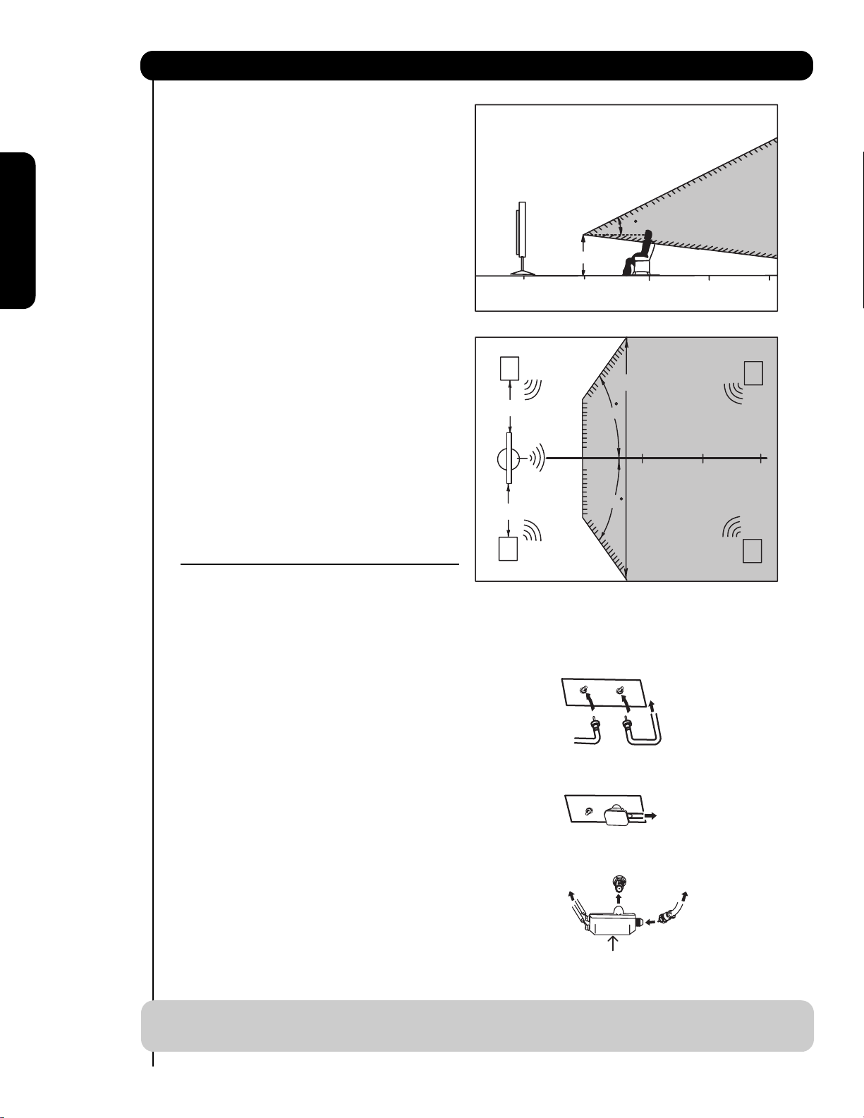
VIEWING
The best picture is seen by sitting directly in front of
the TV and about 10 to 18 feet from the screen.
During daylight hours, reflections from outside light
may appear on the screen. If so, drapes or screens
can be used to reduce the reflection or the TV can
be located in a different section of the room.
If the TV’s audio output will be connected to a Hi-Fi
system’s external speakers, the best audio
performance will be obtained by placing the
speakers equidistant from each side of the receiver
cabinet and as close as possible to the height of
the picture screen center. For best stereo
separation, place the external speakers at least
four feet from the side of the TV, place the surround
speakers to the side or behind the viewing area.
Differences in room sizes and acoustical
environments will require some experimentation
with speaker placement for best performance.
ANTENNA CONNECTIONS TO REAR JACK
PANEL
VHF (75-Ohm) antenna/CATV (Cable TV)
When using a 75-Ohm coaxial cable system, connect CATV coaxial cable to the CABLE (75-Ohm) terminal. If you
have an antenna, connect the coaxial cable to the AIR
terminal.
VHF (300-Ohm) antenna/UHF antenna
When using a 300-Ohm twin lead from an outdoor
antenna, connect the VHF or UHF antenna leads to
screws of the VHF or UHF adapter. Plug the adapter
into the antenna terminal on the TV.
When both VHF and UHF antennas are
connected
Attach an optional antenna cable mixer to the TV
antenna terminal, and connect the cables to the
antenna mixer. Consult your dealer or service store for
the antenna mixer.
NOTE: Connecting a 300-Ohm twin lead connector may cause interference. Using a 75-Ohm coaxial
cable is recommended.
20
3’
0’
5’
10’
BEST
VERTICAL VIEWING
ANGLE
15’
20’
R
S
4" Minimum
4" Minimum
L
80
BEST
HORIZONTAL
5'
10'
VIEWING ANGLE
80
15'
20'
S
To outdoor antenna
CABLE
or CATV cable
AIR
To second antenna
AIR
CABLE
To outdoor VHF
or UHF antenna
To UHF
antenna
AIR
Antenna Mixer
To outdoor antenna
or CATV system
300-Ohm Twin Lead Cable
This outdoor antenna cable must be connected to an
antenna adapter (300-Ohm to 75-Ohm).
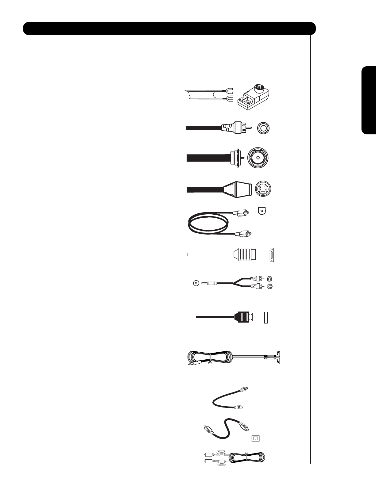
Phono Connector
Used on all standard video and audio cables which
connect to inputs and outputs located on the
television’s rear jack panel and side control panel.
“F” Type 75-Ohm Coaxial Antenna Connector
For connecting RF signals (antenna or cable TV) to the
antenna jack on the television.
S-Video (Super Video) Cable
This cable is used on camcorders, VCRs and laserdisc players with an S-Video feature in place of the
standard video cable to produce a high quality picture.
Optical Cable
This cable is used to connect to an audio amplifier with
an Optical Audio In jack. Use this cable for the best
sound quality.
HDMI Cable
This cable is used to connect your external devices
such as Set-Top-Boxes or DVD players equipped with
an HDMI output connection to the TV’s HDMI input.
Stereo Cable (3.8mm plug to 3.5mm plug)
Used to connect equipment with mini stereo audio jack
to the left and right audio inputs on the rear and side
panels.
USB Cable
This cable is used to connect your digital camera to the
Photo Input in the side of the Plasma television.
IR Mouse Cable/G-LINK Cable (Provided)
Connect the IR Mouse to the IR Blaster output of your
Plasma Television when A/V Network is used. You
must place the IR Mouse in front of the corresponding
IR window of your cable box and VCR. This
connection allows your TV, and the TV Guide On
Screen
TM
system, to control your cable box and/or VCR.
Power Swivel Cable (Provided with 42” Models)
This cable is used to connect the swivel stand to the
rear panel of the Plasma Television.
IEEE1394 Cable
This cable is used to connect your digital television to
external digital devices.This cable will carry both the
video and audio information.
Sub-Woofer Cable
Used to connect the Sub-Woofer Out to the SubWoofer Input of an audio amplifeier (not included).
7
Hook-up Cables and Connectors
First time use
Most video/audio connections between components can be made with shielded video and audio cables that have
phono connectors. For best performance, video cables should use 75-Ohm coaxial shielded wire. Cables can be
purchased from most stores that sell audio/video products. Below are illustrations and names of common
connectors. Before purchasing any cables, be sure of the output and input connector types required by the
various components and the length of each cable.
AUDIO OUT
3.8mm
STEREO
MINI-PLUG
2
RCA TYPE
PLUGS
8
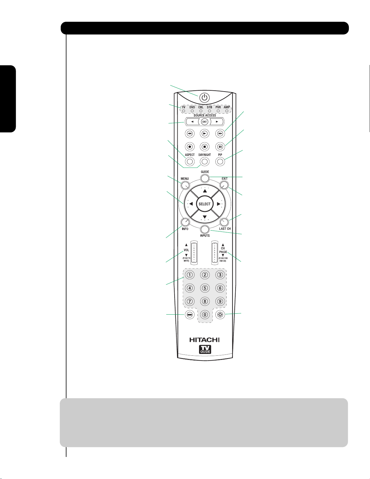
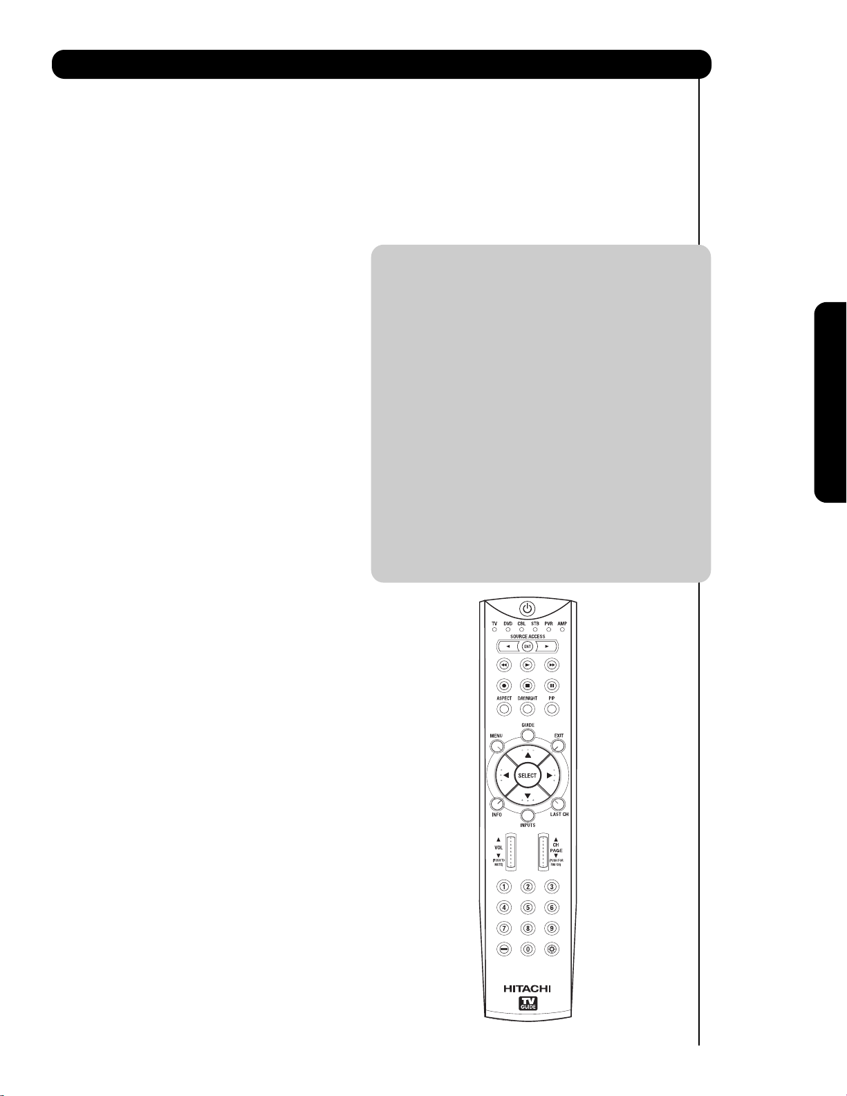
Quick Reference Remote Control Buttons and Functions
First time use
In addition to controlling all of the functions on your HITACHI Plasma TV, the new remote control is designed to
operate different types of devices, such as, DVD Players, CBL (Cable Boxes), set-top-boxes, satellite receivers,
and VCRs. The remote control must be programmed to control the chosen device. Please see pages 23-41 for a
complete description of all features and programming of the Remote Control.
LEGEND
TV – Television VCR – Video Cassette Recorder/Player
CBL – Cable Box DVD – Digital Video Disc Player
STB – Set-Top-Box SAT – Satellite Receiver
NOTES: 1. The TV’s remote control sensor is located on the right bottom portion of the TV screen. To
control TV functions, please point the remote control directly at the remote control sensor for
best results.
2. VCR precode is included in the PVR mode.
3. CD precode is included in the AMP mode.
4. Pressing any button will illuminate the backlight for 4 seconds.
(TV, DVD, CBL, STB, PVR/VCR, AMP/CD)
Turns the selected device on and off.
Turns on or blinks to show remote control
mode when the SOURCE ACCESS buttons
(TV, DVD, CBL, STB, PVR/VCR, AMP/CD)
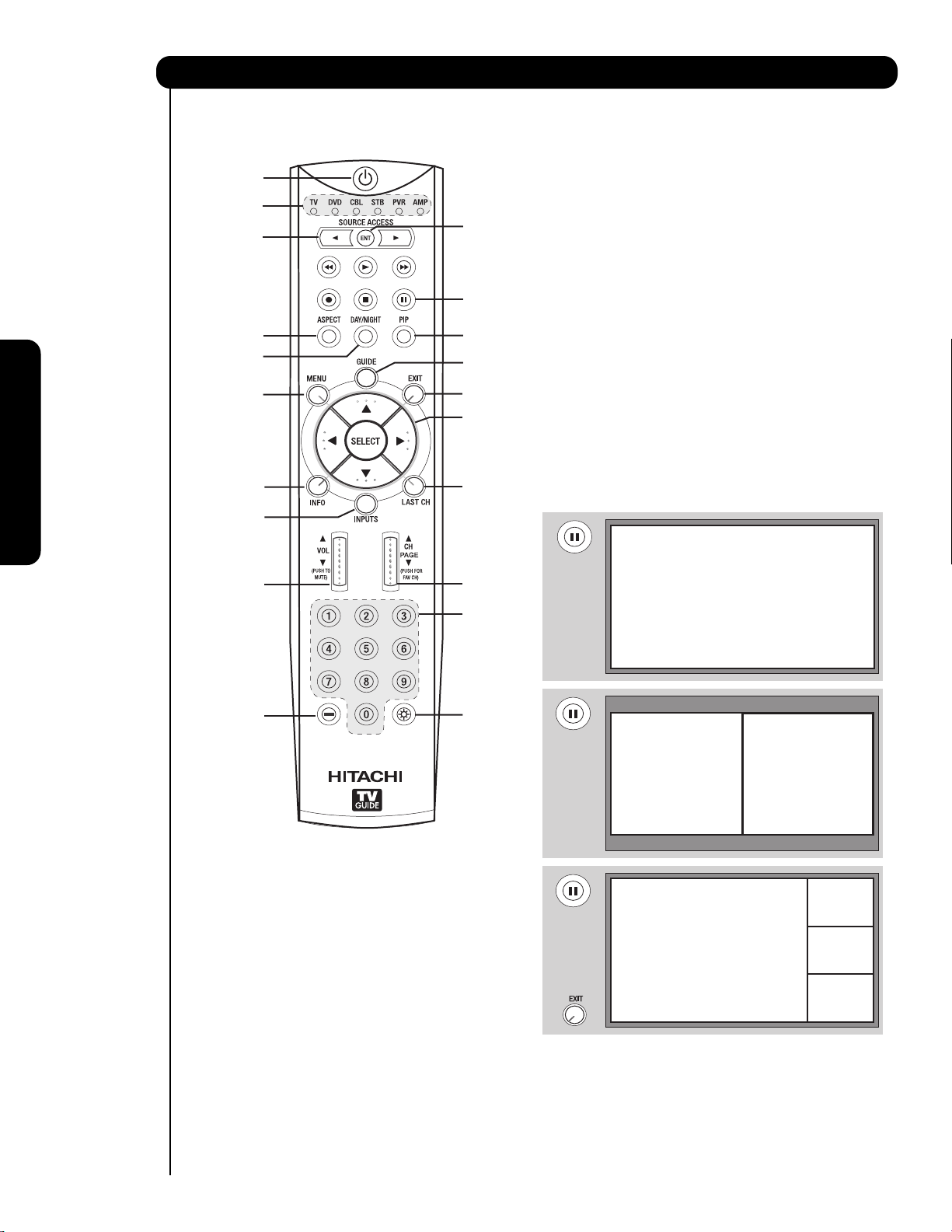
Changes the mode of the Universal Remote
The Cursor Pad is used as a cursor to navigate
through the OSD and INPUT menu systems.
The Select button is used to Select/Activate
Displays various information on the screen,
SOURCE ACCESS BUTTONS
Control to control the device selected.
Changes the aspect ratio of the TV.
Toggles picture mode settings between
(TV, DVD, CBL, STB, PVR/VCR)
Accesses the OSD menu system.
CURSOR PAD/SELECT BUTTON
(TV, DVD, CBL, STB, PVR/VCR)
such as channel information.
POWER BUTTON
MODE INDICATOR
are pressed.
ASPECT BUTTON
DAY and NIGHT mode.
MENU BUTTON
highlighted menu items.
INFO BUTTON
(TV, STB, CBL, PVR)
(TV)
DAY/NIGHT
(TV)
DVD/VCR CONTROL BUTTONS
(DVD, PVR/VCR, AMP/CD)
Controls the functions of your VCR, DVD
and audio devices.
PAUSE BUTTON
(TV,PVR/VCR, DVD, AMP/CD)
Press to show and change the Freeze mode of the TV.
Also used to pause other devices when the remote is in
DVD, PVR/VCR, or AMP/CD mode.
PIP CONTROL BUTTONS
(TV)
Press to show and change the Picture-in-Picture mode.
GUIDE BUTTON
(TV, STB, CBL, PVR)
Accesses the TV Guide On Screen system (see page 54)
of the TV or the program guide of other devices.
EXIT BUTTON
(TV, CBL, STB, PVR/VCR)
Exits out of the OSD, INPUTS or AV NET menu
systems if their menu is displayed.
LAST CHANNEL BUTTON
(TV, CBL, STB, PVR)
Switches between the current and last channel viewed.
INPUTS BUTTON
(TV, AMP)
Accesses the INPUTS menu system.
/
TM
VOLUME WHEEL
Scroll up and down to adjust the audio level of your
Used to manually enter the TV channel, and used
for numeric entry when navigating through the OSD,
TV. Push down on the wheel to mute.
(TV, DVD, CBL, STB, PVR/VCR, AMP/CD)
INPUTS, and AV NET menu systems.
The (-) button is used when the remote is in
Set-Top-Box (STB) mode or when the TV uses
(TV, AMP/CD)
NUMERIC BUTTONS
(-) BUTTON
(TV,STB)
a digital input.
CHANNEL WHEEL
(TV, CBL, STB, PVR/VCR, AMP/CD)
Scroll up or down to change channel. Push down on
the wheel to access (FAV) Favorite Channel mode.
(Favorite channel is only available for TV mode.)
LIGHT BUTTON
(TV, CBL, STB, PVR)
Press to use the back light feature. Can
also be used to change backlight mode.
9
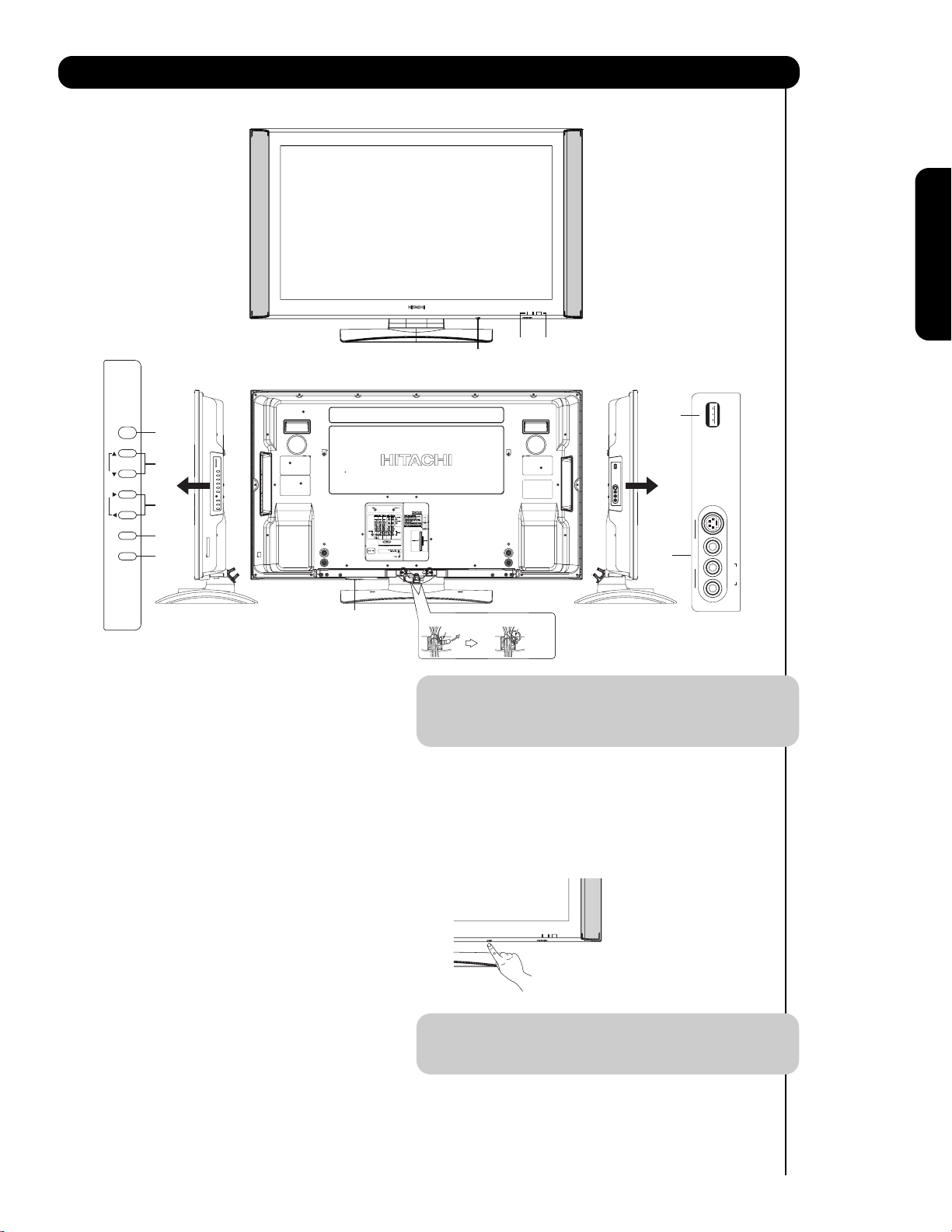
Front/Rear/Side Panel Controls
First time use
INPUT
PHOTO
INPUT 5
CURSOR
REAR/SIDE VIEW
FRONT VIEW
The Main Power
button is located on
the broadside
bottom, under the
label “MAIN
POWER”.
SIDE POWER button
Press this button to turn the Plasma Television
ON/OFF. It can also be turned ON/OFF by remote
control. The “MAIN POWER” button must be at
stand-by mode.
MENU/SELECT button
This button allows you to enter the MENU, making
it possible to set TV features to your preference
without using the remote. This button also serves
as the SELECT button when in MENU mode.
햴
PHOTO INPUT
Insert USB cable from your Digital Camera, USB
memory or memory card USB drive to view your
digital still pictures (see pages 27 and 28).
INPUT/EXIT button
Press this button to access the INPUT menu.
Press again to exit the MENU mode.
CHANNEL selector
Press these buttons until the desired channel
appears in the top right corner of the TV screen.
These buttons also serve as the cursor down ()
and up () buttons when in MENU mode.
VOLUME level
Press these buttons to adjust the sound level. The
volume level will be displayed on the TV screen.
These buttons also serve as the cursor left () and
right () buttons when in MENU mode.
NOTE: The Rear View of the 55” model is slightly
different from the 42” models. One of the
differences are the handles that are only
present on the 42” models.
POWER button
Display Monitor “MAIN POWER” button
This power button is for the complete system, and
must be turned ON/OFF manually. It is
recommended to leave the “MAIN POWER” to ON
condition (lights red) for stand-by mode.
NOTE: When the “MAIN POWER” button is set to
OFF or the TV is unplugged, the clock will
stop and may eventually reset itself.
POWER
+
CH
-
CH
CURSOR
+
VOL
-
VOL
INPUT/EXIT
MENU/SELECT
Firmly bind the cables.
Thread the square
hole with the band.
Hook the band
to the claw.
INPUT
PHOTO
INPUT 5
L/MONO
R
S-VIDEO
VIDEO
AUDIO
10
POWER light indicator
To turn the monitor ON, press the main power
switch located on the lower right side of the
monitor. A red stand-by indicator lamp located on
the lower right corner of the front bezel will
illuminate. The Plasma TV is now ready for remote
ON/OFF operation.
REMOTE CONTROL sensor
Point your remote at this area when selecting
channels, adjusting volume, etc.
LEARNING AV NET sensor
Point your equipment’s remote control at this area
while using the AV NET Learning Wizard.
SIDE INPUT JACKS (for VIDEO: 5)
Use these audio/video jacks for a quick hook-up
from a camcorder or VCR to instantly view your
favorite show or new recording. Press the INPUTS
button then use the CURSOR PAD and the SELECT
button on the remote control to select INPUT 5. If
you have mono sound, insert the audio cable into
the left audio jack.
IEEE1394 (DV Input)
This input provides a digital interface for your
external digital devices such as your digital video
(DV) camcorder.
Front/Rear/Side Panel Controls
First time use
NOTES: 1. Your HITACHI Plasma TV will appear to be turned OFF (lights orange) if there is no video input
when VIDEO: 1, 2, 3, 4 and 5. Check the Power Light to make sure the Display Monitor is
turned off or in Stand-by mode (lights red) when not in use.
2. Remote Control can not turn ON/OFF the “MAIN POWER” of the display monitor.
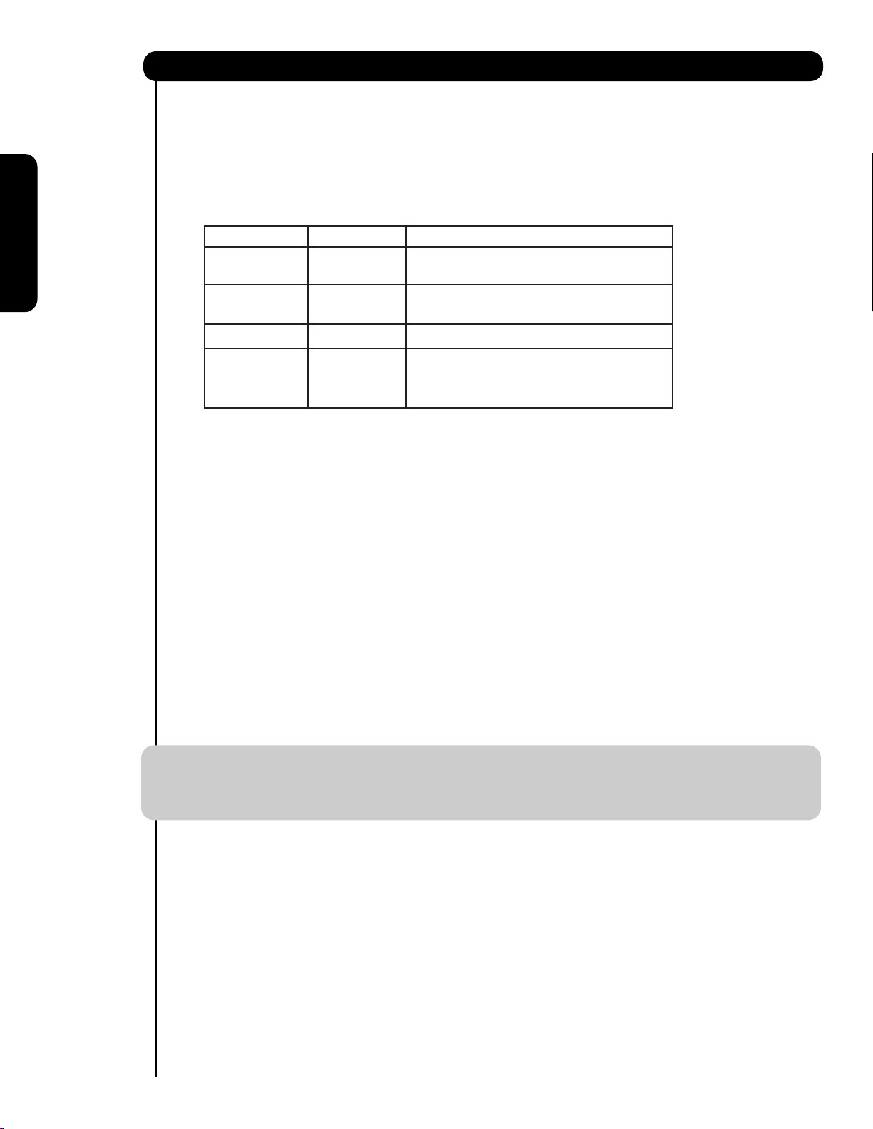
Indicating Lamp Power Status Operating
Off Off When the main power switch is set to
OFF.
Lights Red Off When the main power switch on the display
(Stand-by) monitor is ON.
Lights Green On Display monitor MAIN POWER is ON.
Lights Orange Off Display monitor MAIN POWER is ON
(Power Saving) with no signal input except antenna
(no sync. signal).
Antenna Input
The remote control allows you to switch between
two separate 75-Ohm RF antenna inputs, CABLE
and AIR.
Audio/Video INPUTS 1, 2, 3 and 4
By using the INPUTS button, the CURSOR PAD (
and ), and the SELECT button or CURSOR PAD
of the remote control, you can select each video
source. Use the audio and video inputs to connect
external devices, such as VCRs, camcorders,
laserdisc players, DVD players etc. (if you have
mono sound, insert the audio cable into the left
audio jack).
햴 MONITOR OUT & HI-FI AUDIO OUT
These jacks provide fixed and variable audio and
video signals (CABLE/AIR, INPUT 1, 2 and 5)
which are used for recording. Use the S-VIDEO
Output for high quality video output. Component
signal to INPUT 3 and 4, and HDMI inputs will not
have monitor output.
Optical Out (Digital Audio)
This jack provides Digital Audio Output for your
audio device that is Dolby
®
Digital and PCM
compatible, such as an audio amplifier.
NOTE: *Manufactured under license from Dolby
Laboratories. “Dolby” and the double-D
symbol are trademarks of Dolby
Laboratories.
S-VIDEO INPUTS 1 and 2
INPUTS 1 and 2 provide S-VIDEO (Super Video)
jacks for connecting equipment with S-VIDEO
output capability.
NOTE: 1. You may use VIDEO, HDMI or S-VIDEO
inputs to connect to INPUT 1 and 2, but only
one of these inputs may be used at a time.
2. S-VIDEO output may be used for
recording, only when the input is of SVIDEO type.
HDMI INPUTS 1 and 2 (High Definition
Multimedia Interface)
ABOUT HDMI – HDMI is
the next-generation all digital interface for
consumer electronics. HDMI enables the secure
distribution of high-definition video and multichannel audio in a single cable. Because digital
television (DTV) signals remain in digital format,
HDMI assures that pristine high-definition images
retain the highest video quality from the source all
the way to your television screen.
Use the HDMI input for your external devices such
as Set-Top-Boxes or DVD players equipped with an
HDMI output connection.
HDMI, the HDMI logo and High-Definition
Multimedia Interface are trademarks or registered
trademarks of HDMI Licensing LLC.
NOTE: 1. The HDMI input is not intended for use
with personal computers.
2. Only DTV formats such as 1080i, 720p, 480i
and 480p are available for HDMI input.
Component: Y-P
BPR Inputs
INPUTS 3 and 4 provide Y-P
BPR jacks for
connecting equipment with this capability, such as
a DVD player or Set Top Box. You may use
composite video signal for both inputs.
NOTE: 1. Do not connect composite VIDEO and
S-VIDEO to INPUT 1, 2 or 5 at the same
time. S-VIDEO has priority over VIDEO input.
2. Your component outputs may be labeled
Y, B-Y, and R-Y. In this case, connect the
components B-Y output to the TV’s P
B
input and the components R-Y output to
the TV’s P
R input.
3. Your component outputs may be labeled
Y-C
BCR. In this case, connect the component
C
B output to the TV’s PB input and the
component C
R output to the TV’s PR input.
4. It may be necessary to adjust TINT to
obtain optimum picture quality when using
the Y-P
BPR inputs (see page 44).
5. To ensure no copyright infringement, the
MONITOR OUT output will be abnormal,
when using the Y-P
BPR jacks.
6. INPUT 3 and INPUT 4 (Y/VIDEO) can be
used for composite video and component
video input.
IR Blaster/G-LINK
This jack provides IR output to your external
components (VCR, Cable box, DVD player, etc.).
With this connection, your external components
can automatically be controlled by the A/V network
feature. This connection will allow you to control
the external components with your Plasma
Television’s remote control in TV mode. The GLINK connection will enable the TV Guide On
Screen
TM
recording feature.
For Service Use Only
Do not connect anything to this terminal.
Specifically for Service use only.
11
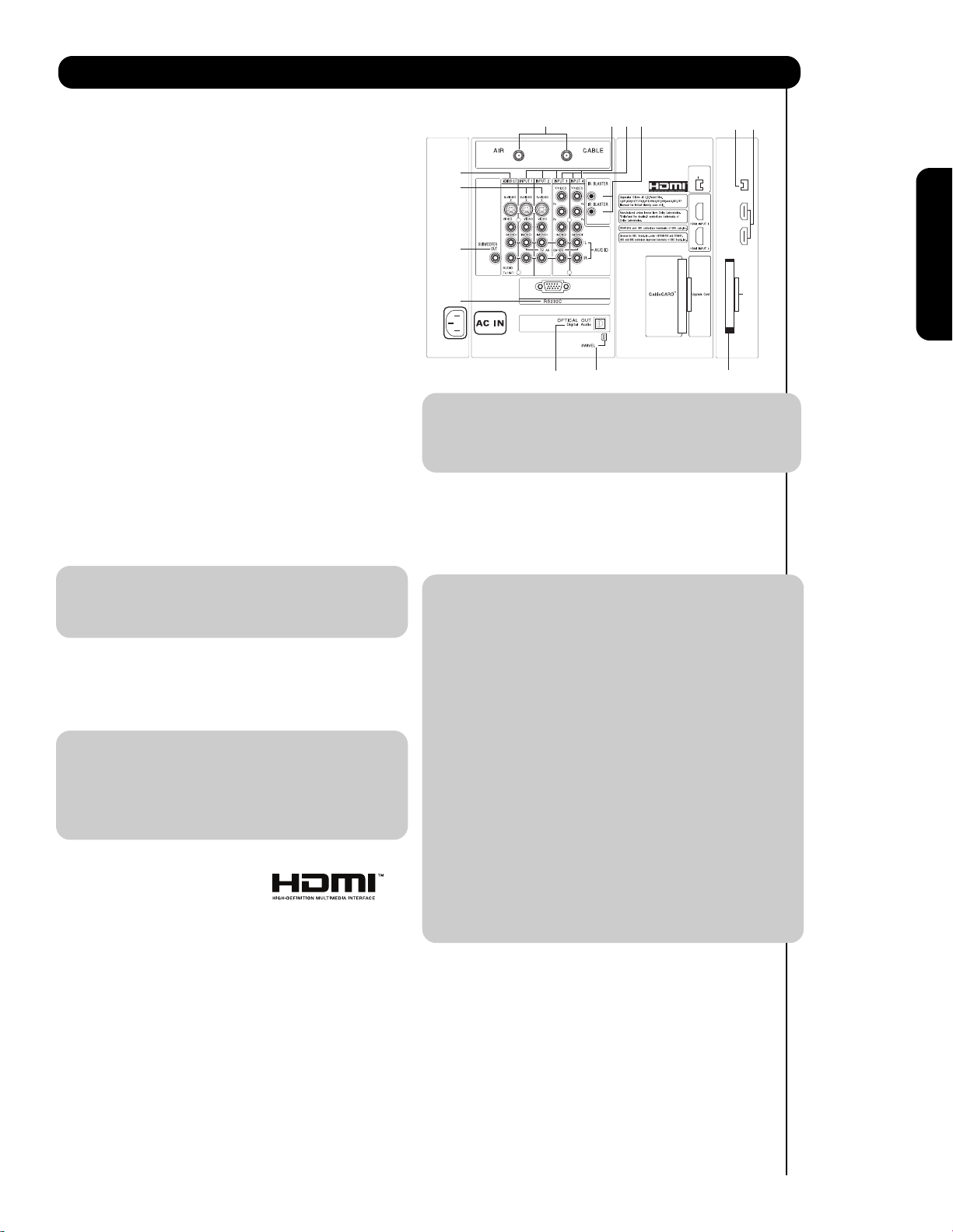
Rear Panel Connections
First time use
G-LINK
/
IEEE1394
DV INPUT
12
Subwoofer Out
Connect this SUB WOOFER OUT output to the
external audio component input using the sub
woofer cable (not provided).
Upgrade Card
This card slot is for future software upgrades.
HITACHI will notify you if a software upgrade is
required for your TV. In order to receive written
notification, please complete and return your
warranty card.
To Power Swivel Connector
Connects to the Power Swivel Table Top Stand.
IEEE1394 (DV INPUT)
These jacks provide a digital interface for your
external digital devices, such as a Digital VCR (DVHS), Set-Top-Box or Digital Camcorder by means
of a single cable (see page 19). When using
IEEE1394 connections, you enable video and audio
digital data exchange between a compatible
device. This connection also enables you to
control basic equipment functions (such as VCR
play, rewind, fast forward, stop, etc.) from your TV
On-Screen Display.
CableCARD Slot
This slot is for the CableCARD that will be provided
by your local cable operator to gain access to
chosen cable channels. Please call your local cable
operator if this service is available before
requesting a CableCARD (also known as Point of
Deployment (POD) module).
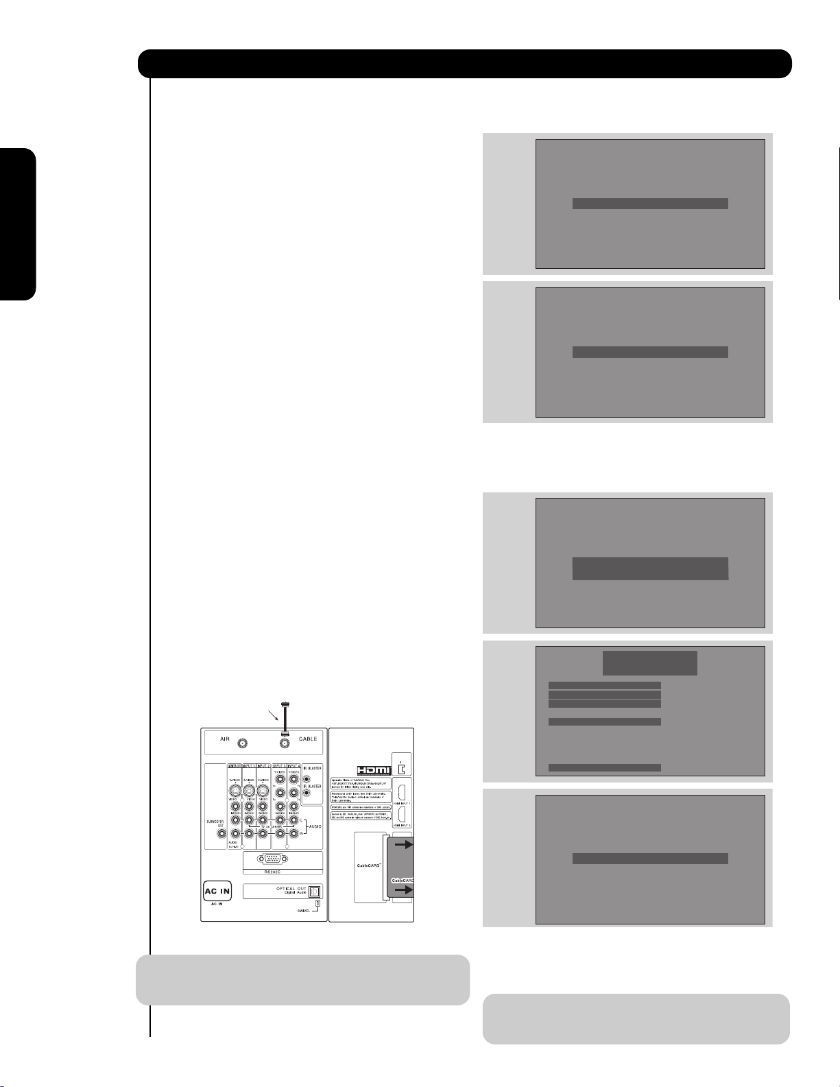
1. Connect a coaxial cable to cable terminal of
the Rear Panel Jacks.
2. Insert the CableCARD into the slot (Top of card
should be facing towards you as shown
below).
NOTE: 1. A digital cable subscription is required.
2. Do not insert a PCMCIA card into the
CableCARD slot.
If the CableCARD is properly installed or not installed,
the TV will display the following respective screens.
After the CableCARD is installed, wait until the second
screen below appears. The third screen below will
appear if a channel is not authorized for viewing. Press
the EXIT button to exit the second screen.
Please take note of all information on the screen (you
will provide this information to your cable operator).
Call your cable operator and give them the information
from the card to start your cable service.
NOTE: Please see Appendix E on page 101 for
additional CableCARD information.
Rear Panel Connections
First time use
TINSERT
T
CableCARD is installed
OR
CableCARD is not installed
Digital Cable
IEEE1394
/
G-LINK
DV INPUT
INSER
INSER
OR
Acquiring Data.
Please wait.
In order to start cable service
for this device, please contact
your cable provider
CableCARD(tm): 123-456-789-1
Host: 123-456-789-1
Data: 123-456-789-1
Unit Address: 123-456-789-1
Press EXIT to return
Not an Authorized Channel
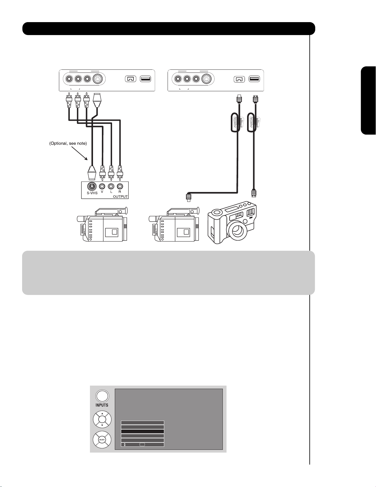
The front panel jacks are provided as a convenience to allow you to easily connect your video camcorder, digital
camera or Digital Video Camcorder as shown in the following examples:
NOTE: 1. Completely insert connection cord plugs when connecting to left side panel jacks. If you do not, the
played back picture may be abnormal.
2. If you have a S-VHS VCR, use the S-VIDEO cable in place of the standard video cable.
3. If you have a mono VCR, insert the audio cable into the left audio jack of your TV.
4. S-VIDEO input takes priority over VIDEO input.
5. If you have a VHS or 8mm camcorder, use the S-VIDEO cable in place of the VIDEO cable.
The exact arrangement you use to connect the VCR, camcorder, laserdisc player, DVD player, or HDTV Set
Top Box to your Plasma TV is dependent on the model and features of each component. Check the
owner’s manual of each component for the location of video and audio inputs and outputs.
The following connection diagrams are offered as suggestions. However, you may need to modify them to
accommodate your particular assortment of components and features. For best performance, video and
audio cables should be made from coaxial shielded wire.
Before Operating External Video Source
Connect an external source to one of the INPUT terminals, then press the INPUTS button to show the
INPUTS menu. Use the CURSOR PAD ( and ) to select the Antenna or Input of your choice. Then press
the SELECT button or the CURSOR PAD to confirm your choice (see page 26).
13
Connecting External Video Sources
First time use
Left Side Panel Left Side Panel
R
AUDIO
L/MONO
VIDEO
S-VIDEO
INPUTINPUT
PHOTOPHOTO
INPUT 5INPUT 5
R
AUDIO
L/MONO
VIDEO
S-VIDEO
INPUTINPUT
PHOTOPHOTO
INPUT 5INPUT 5
IEEE1394IEEE1394
DV INPUTDV INPUT
IEEE1394IEEE1394
DV INPUTDV INPUT
IEEE 1394IEEE 1394
CableCable
Video CameraVideo Camera
Digital Video CamcorderDigital Video Camcorder
Digital CameraDigital Camera
Ferrite Ferrite
CoreCore
Ferrite Ferrite
CoreCore
USBUSB
CableCable
1. Wrap once the USB cable or IEEE
1394 cable (not supplied) on the
ferrite core near the Photo Input
or IEEE 1394 Input as shown.
S-Video cable
2. Fold and close the ferrite core
while being careful not to pinch
the cable.
Ferrite Core Instructions:Ferrite Core Instructions:
Photo Input
IEEE 1394
Cable
Air
Input 1
Move SEL Sel.
14
Rear Panel Connections
First time useThe Remote ControlOn-Screen Display
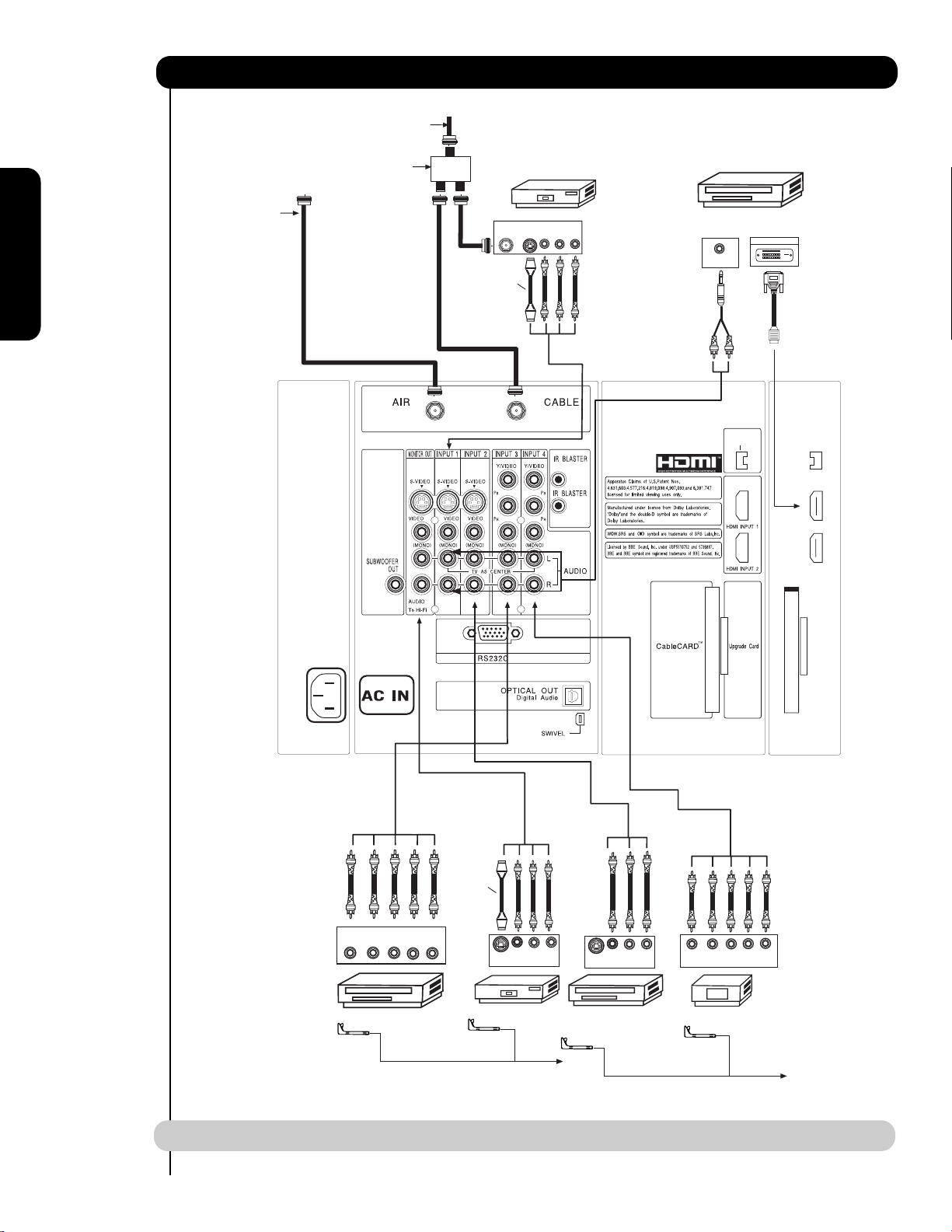
A
NOTE: Cables are optional, except when specified.
Cable TV coaxial cable
2-Way signal splitter
Outside
ntenna
ANT
IN
Optional
S-VIDEO
VCR #1
OUTPUT
VLR
G-LINK
DIGITAL
OUTPUT CAPABILITY
AUDIO OUT
/
IEEE1394
DV INPUT
DIGITAL OUTPUT
DVI
to
HDMI
OUTPUT
YP
B/CBPR/CR
L R
DVD Player
(PROVIDED)
Optional
V L R
S-VIDEO
INPUT
VCR #2
CONNECT TO
IR BLASTER
V L R
S-VIDEO
OUTPUT
Laserdisc player, VCR,
camcorder, etc.
(PROVIDED)
Y P
P
B
OUTPUT
HDTV Set-Top Box
L R
R
CONNECT TO
IR BLASTER/
G-LINK

• S-VIDEO, YPBPR, or HDMI connections are provided for high performance laserdisc players, VCRs etc.
that have this feature. Use these connections in place of the standard video connection if your device has
this feature.
• If your device has only one audio output (mono sound), connect it to the left audio jack on (L/(MONO)) the
Rear Panel.
• Refer to the operating guide of your other electronic equipment for additional information on connecting
your hook-up cables.
• A single VCR can be used for VCR #1 and VCR #2, but note that a VCR cannot record its own video or line
output (INPUT: 1 in the example on page 14). Refer to your VCR operating guide for more information on
line input-output connections.
• Connect only 1 component (VCR, DVD player, camcorder, etc.) to each input jack.
• COMPONENT: Y-PBPR (Input 3 & 4) connections are provided for high performance components, such as
DVD players and set-top-boxes. Use these connections in place of the standard video connection if your
device has this feature.
• Your component outputs may be labeled Y, B-Y, and R-Y. In this case, connect the components B-Y
output to the TV’s PBinput and the components R-Y output to the TV’s PRinput.
• Your component outputs may be labeled Y-CBCR. In this case, connect the components CBoutput to the
TV’s PBinput and the components CRoutput to the TV’s PRinput.
• It may be necessary to adjust TINT to obtain optimum picture quality when using the Y-PBPRinputs. (See
page 44)
• To ensure no copyright infringement, the MONITOR OUT output will be abnormal, when using the Y-PBPR,
and HDMI input jacks.
• INPUT 1 or 2 can accept HDMI signal.
• S-VIDEO monitor output may be used for recording only when the input is of S-VIDEO type.
• When using a HDMI input from a Set-Top-Box, it is recommended to use a 1080i or 720p input signal.
MACROVISION NOTES:
1. Video signals fed through a VCR may be affected by copyright protection systems and the picture will be
distorted on the television.
2. Connecting the television directly to the Audio /Video output of a Set-Top-Box will assure a more normal
picture.
15
Tips on Rear Panel Connections
First time use
16
Connecting External Video Sources
First time useThe Remote ControlOn-Screen Display
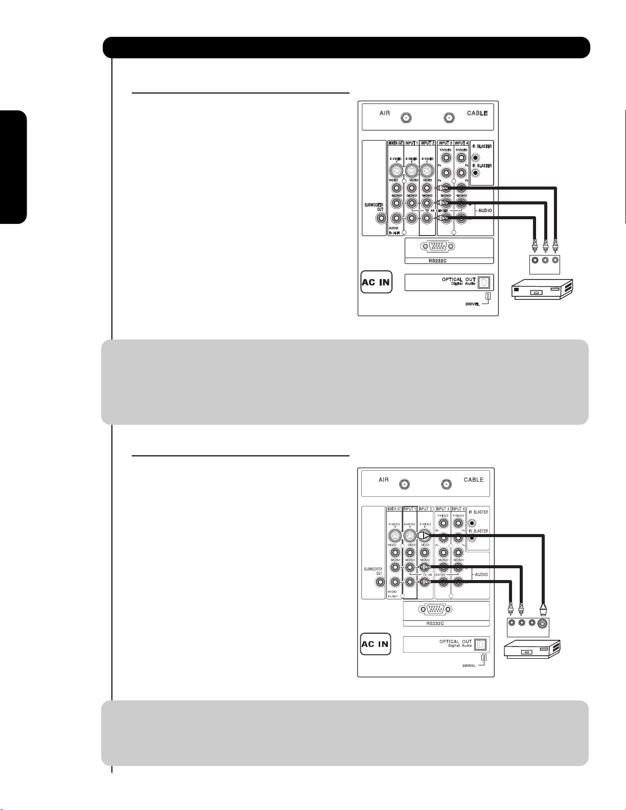
CONNECTING A VIDEO AND STEREO AUDIO
SOURCE TO INPUT1 – INPUT5
1. Connect the cable from the VIDEO OUT of the
VCR or the laserdisc player to the INPUT
(VIDEO) jack, as shown on the Rear Panel on the
right.
2. Connect the cable from the AUDIO OUT R of the
VCR or the laserdisc player to the INPUT
(AUDIO/R) jack.
3. Connect the cable from the AUDIO OUT L of the
VCR or the laserdisc player to the INPUT
(AUDIO/L) jack.
4. Press the INPUTS button, then select INPUT 2
from the INPUTS menu to view the program
from the VCR or laserdisc player.
5. Select CABLE or AIR from the INPUTS menu to
return to the last channel tuned.
NOTE: 1. Completely insert the connection cord plugs when connecting to rear panel jacks. The picture and
sound that is played back will be abnormal if the connection is loose.
2. A single VCR can be used for VCR #1 and VCR #2 (see page 14) but note that a VCR cannot record
its own video or line output. Refer to your VCR operating guide for more information on line inputoutput connections.
3. When INPUT 3 or 4 are used, it is necessary to connect the video output of the device to the
Y/VIDEO input jack of the TV.
CONNECTING AN S-VIDEO AND STEREO AUDIO
SOURCE TO INPUT 1, 2 AND 5
1. Connect the cable from the S-VIDEO OUT of
the S-VHS VCR or the laserdisc player to the
INPUT (S-VIDEO) jack, as shown on the Rear
Panel on the right.
2. Connect the cable from the AUDIO OUT R of
the VCR or the laserdisc player to the INPUT
(AUDIO/R) jack.
3. Connect the cable from the AUDIO OUT L of
the VCR or the laserdisc player to the INPUT
(AUDIO/L) jack.
4. Press the INPUTS button, then select INPUT 1
from the INPUTS menu to view the program
from the VCR or laserdisc player.
5. Select CABLE or AIR from the INPUTS menu to
return to the last channel tuned.
NOTE: 1. Completely insert the connection cord plugs when connecting to rear panel jacks. The picture and
sound that is played back will be abnormal if the connection is loose.
2. A single VCR can be used for VCR #1 and VCR #2 (see page 14), but note that a VCR cannot record
its own video or line output. Refer to your VCR operating guide for more information on line inputoutput connections.
G-LINK
Back of
VCR
R L V
OUTPUT
VCR
G-LINK
/
R L V
OUTPUT
Back of
VCR
VCR
G-LINK
/
R L V
VCR or Laserdisc Player
OUTPUT
S-VIDEO
Back of VCR or
Laserdisc Player
17
Connecting External Video Sources
First time use
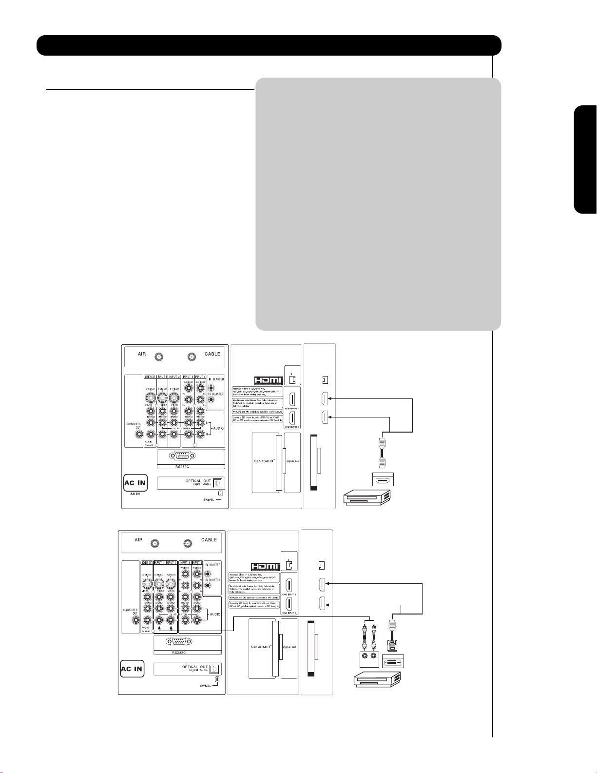
CONNECTING A COMPONENT SOURCE WITH
HDMI OR DVI CAPABILITY TO INPUT 1 OR 2
1. Connect the HDMI or DVI output of the HDTV
set top box or DVD player to the HDMI input as
shown on the Rear panel below.
2. With DVI output, connect the cable from the
AUDIO OUT R of the HDTV set top box or DVD
player to the INPUT (AUDIO/R) jack as shown on
the Rear Panel below.
3. With DVI output, connect the cable from the
AUDIO OUT L of the HDTV set top box or DVD
player to the INPUT (AUDIO/L) jack as shown
on the Rear Panel below.
4. Press the INPUTS button, then select INPUTS 1
or 2 to view the program from the HDTV set top
box or DVD player.
5. Select CABLE or AIR from the INPUTS menu to
return to the last channel tuned.
NOTE: 1. Completely insert the connection cord
plugs when connecting to rear panel jacks.
The picture and sound that is played back
will be abnormal if the connection is loose.
2. The HDMI input on INPUT 1 and 2
contains the copy protection system called
High-bandwidth Digital Content Protection
(HDCP). HDCP is a cryptographic system
that encrypts video signals when using
HDMI connections to prevent illegal
copying of video contents.
3. HDMI is not a “NETWORK” technology. It
establishes a one-way point-to-point
connection for delivery of uncompressed
video to a display.
4. The connected digital output device
controls the HDMI interface so proper setup of device user settings determines final
video appearance.
5. When using a DVI to HDMI cable, connect
the Audio Out L and R cables at the same
INPUT (1 or 2) as your HDMI INPUT (1 or
2).
HDMI input
DVI to HDMI Input
or
IEEE1394
IEEE1394
DV INPUT
DV INPUT
DIGITAL OUTPUT
HDTV Set-Top-Box or
DVD Player
P
P
B
R
LR
OUTPUT
or
HDMI
Cable
Back of
HDTV Set-Top-Box or
DVD Player
DVI to HDMI
DIGITAL OUTPUT
or
Cable
Back of
HDTV Set-Top-Box or
DVD Player
/
G-LINK
/
G-LINK
HDTV Set-Top-Box or
DVD Player
18
Connecting External Video Sources
First time use
CONNECTING A COMPONENT AND STEREO
AUDIO SOURCE TO INPUT 3 OR 4: Y-PBPR.
1. Connect the cable from the Y OUT of the
Laserdisc/DVD player or HDTV set top box to
the INPUT (Y) jack, as shown on the Rear
panel below.
2. Connect the cable from the PB/CBOUT or BY OUT of the Laserdisc/DVD player or HDTV
set top box to the INPUT (PB)jack.
3. Connect the cable from the PR/CROUT or RY OUT of the Laserdisc/DVD player or HDTV
set top box to the INPUT (PR) jack.
4. Connect the cable from the AUDIO OUT R of
the Laserdisc/DVD player or HDTV set top box
to the INPUT (AUDIO/R) jack.
5. Connect the cable from the AUDIO OUT L of
the Laserdisc/DVD player or HDTV set top box
to the INPUT (AUDIO/L) jack.
6. Press the INPUTS button, then select INPUT 4
from the INPUTS menu to view the program
from the Laserdisc/DVD player or HDTV set
top box.
7. Select CABLE or AIR to return to the last
channel tuned.
NOTE: 1. Completely insert the connection cord
plugs when connecting to rear panel jacks.
The picture and sound that is played back
will be abnormal if the connection is loose.
2. See page 15 for tips on REAR PANEL
CONNECTIONS.
G-LINK
/
OUTPUT
L R Y P
HDTV Set-Top Box
AUDIO
L R
Back of
DVD Player
P
B
R
OR
VIDEO
PR/CR PB/C
DVD Player
OUTPUT
B Y
19
Connecting External Video Sources
First time use
CONNECTING A COMPONENT SOURCE WITH
DIGITAL INTERFACE CAPABILITY TO IEEE1394
TERMINALS.
1. Connect the IEEE1394 cable from the output of the
component with IEEE1394 capability, such as a
Digital VCR or AVHD (External Hard Drive) Digital
Recorder, to the IEEE1394 input terminals shown
below. IEEE 1394 allows the plasma television and
the external device to communicate with one
another. When using IEEE1394 connections, you
enable video and audio digital data exchange
between a compatible device. This connection also
enables you to control basic equipment functions
(such as VCR play, rewind, fast forward, stop, etc.)
from your TV On-Screen Display.
2. Press the INPUTS button on the Remote Control.
3. Select the IEEE1394 option (see page 29).
NOTE: 1. With IEEE1394 connection, video and
audio will be received by the TV. It will
enable you to control the D-VHS from the
TV IEEE1394 menu (see page 29).
2. The IEEE1394 interface contains the copy
protection standard called 5C or Digital
Transmission Content Protection (DTCP).
G-LINK
IEEE1394
/
DV INPUT
LINE OUT
(MONO)/L VIDEO
R
1
(MONO)/L VIDEO
R
2
Digital VCR (D-VHS)
S-VIDEO
S-VIDEO
DIGI TAL INTERF ACE
IEEE1394
IEEE1394 Cabl e
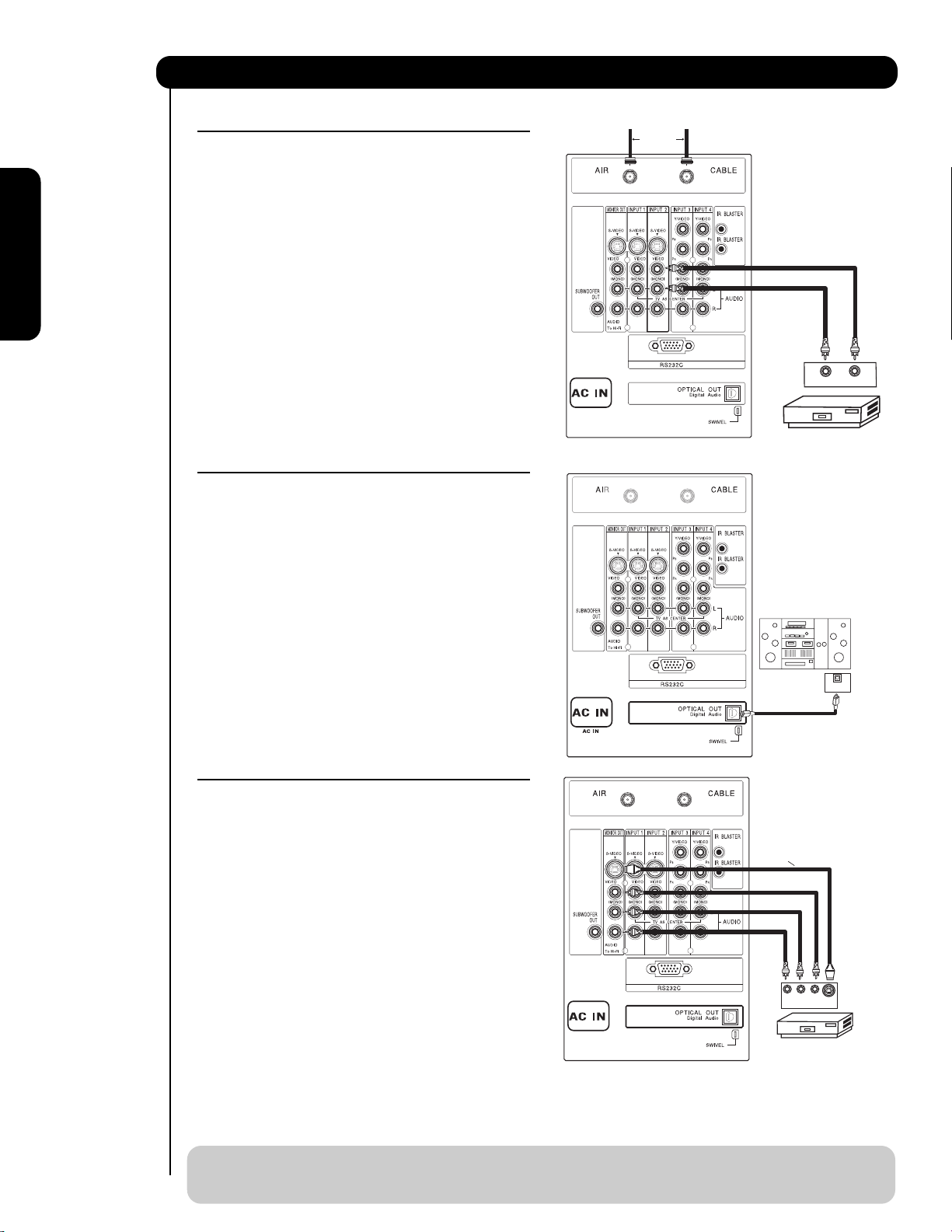
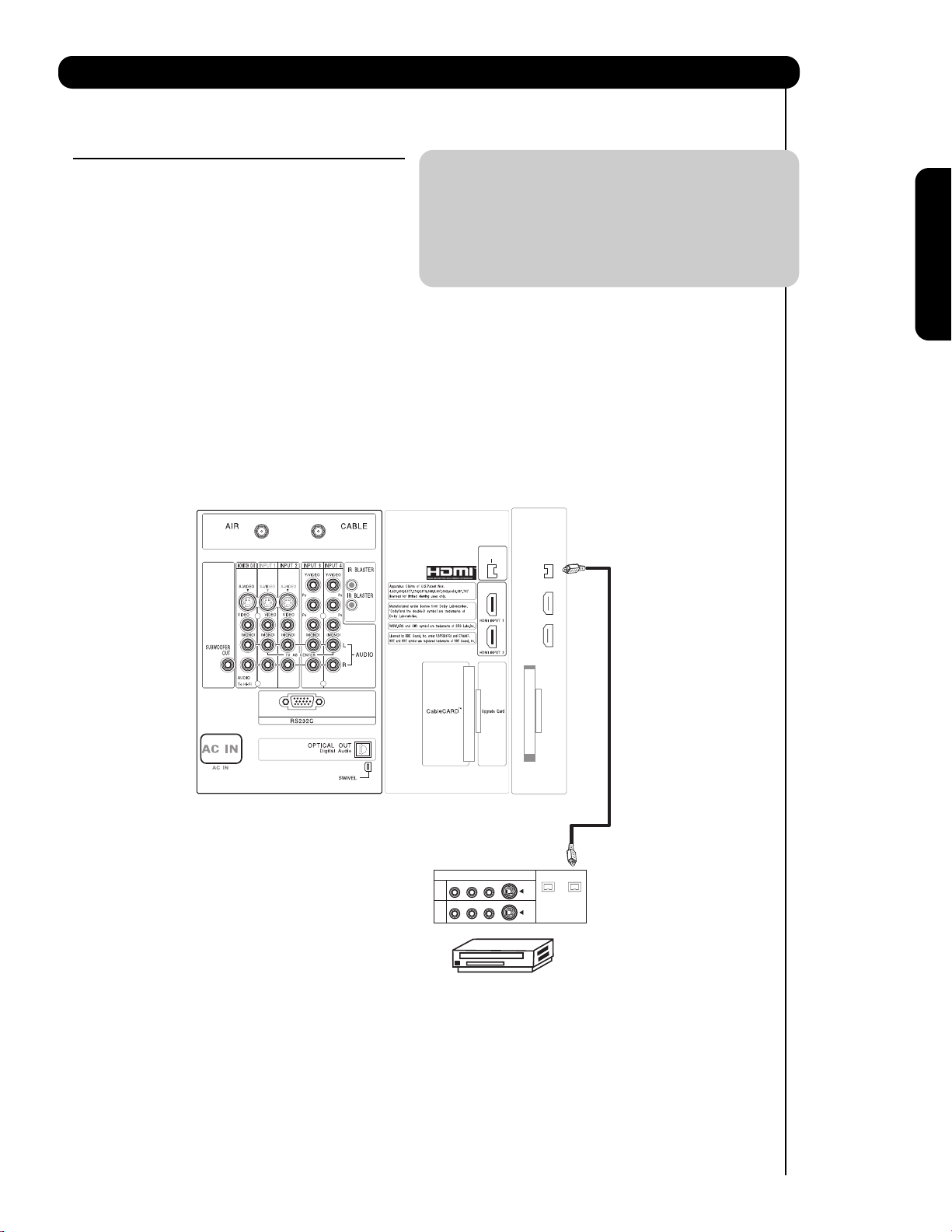
CONNECTING A VIDEO AND MONAURAL AUDIO
SOURCE TO INPUT 1, INPUT 2 OR INPUT 5
1. Connect the cable from the VIDEO OUT of the
VCR or the laserdisc player to the INPUT
(VIDEO) jack, as shown on the Rear Panel on the
right.
2. Connect the cable from the AUDIO OUT of the
VCR or the laserdisc player to the INPUT
(MONO)/L(AUDIO) jack.
3. Press the INPUTS button, then select INPUT 2
from the INPUTS menu to view the program
from the VCR or the laserdisc player.
4. Select CABLE or AIR from the INPUTS menu to
return to the last channel tuned.
CONNECTING AN EXTERNAL AUDIO AMPLIFIER
To monitor the audio level of the Plasma TV to an
external audio amplifier, connect the system as
shown on the right. The “OPTICAL OUT” from the
Rear Panel is a fixed output. The Volume of the
amplifier is controlled by the amplifier, not by the
Plasma Television. The OPTICAL OUT terminal
outputs all audio sources with Optical IN capability.
1. Connect an optical cable from the Optical out to
the Optical input of a separate Stereo System
Amplifier as shown on the Rear Panel on the
right.
CONNECTING MONITOR OUT
The MONITOR OUT terminal outputs video and
audio of CABLE/AIR and INPUTS 1, 2, 3, 4 and 5. It
does not output component video.
1. Connecting S-Video:
Connect the cable from the S-VIDEO OUT of
the Rear Panel to the INPUT (S-VIDEO) jack, of
the VCR or Laserdisk player.
Connecting Video:
Connect the cable from the VIDEO INPUT of
the VCR or the laserdisc player to the VIDEO
out jack on the TV Rear Panel.
2. Connect the cable from the AUDIO IN R of the
VCR or the laserdisc player to the OUTPUT
(AUDIO/R) jack on the TV Rear Panel.
3. Connect the cable from the AUDIO IN L of the
VCR or the laserdisc player to the OUTPUT
(AUDIO/L) jack on the TV Rear Panel.
20
First time use
Connecting External Audio/Video Devices
NOTE: 1. When making video connections, connect S-Video only or Video only. If both are connected, S-
Video takes priority (see table on page 8).
2. For further information on using MONITOR OUT, refer to pages 88 and 89.
Connect the
Cable and/or
Air cables
G-LINK
/
G-LINK
/
Stereo System Amplifier
AUDIO OUT
VCR
OPTICAL
INPUT
VIDEO OUT
Back of VCR
G-LINK
/
Optional
R L V
S-VIDEO
INPUT
VCR or other external
components
21
Connecting External Video Sources
First time use
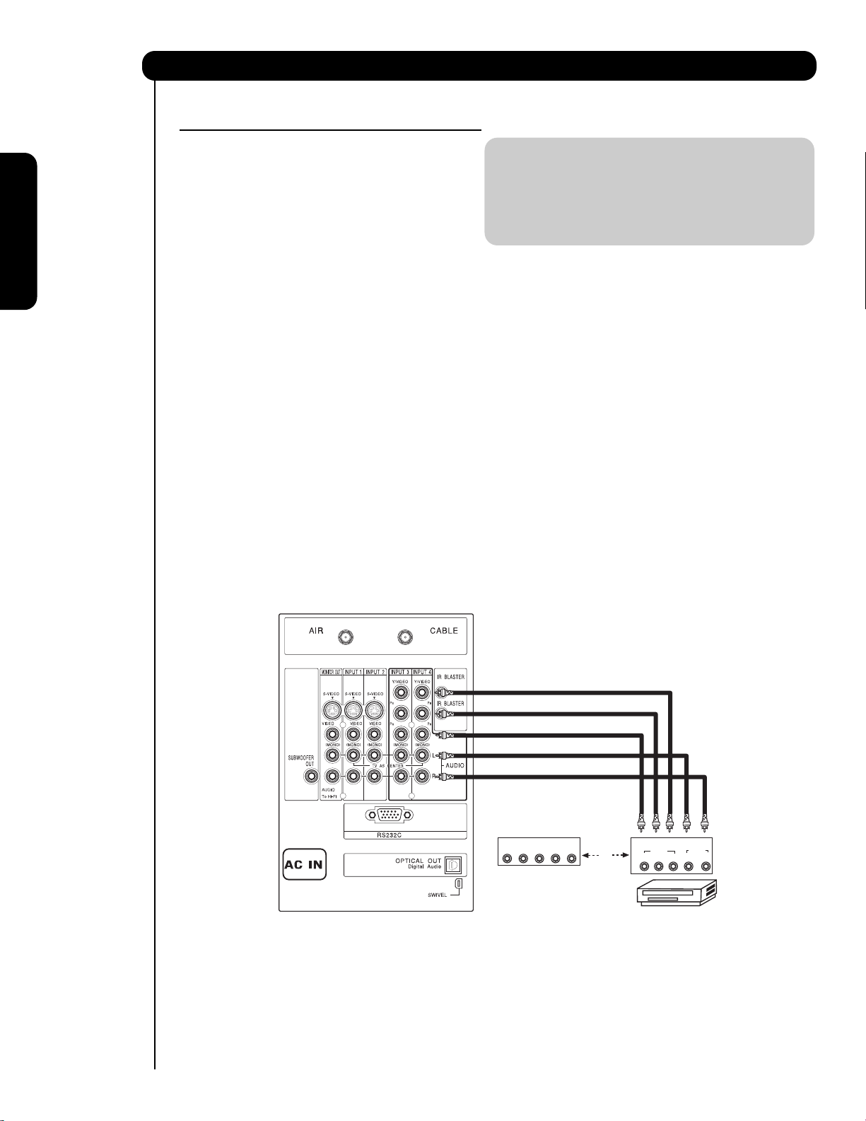
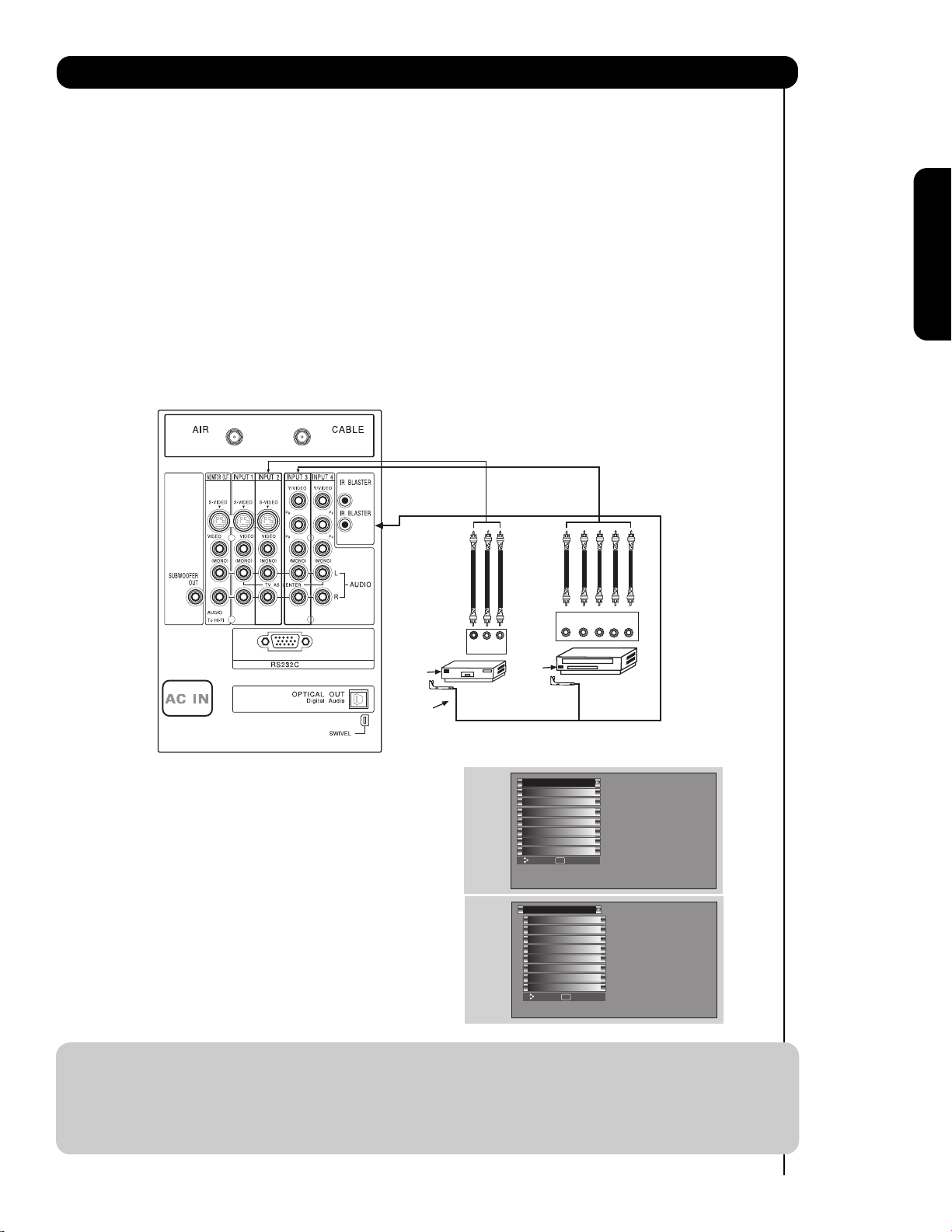
Your Hitachi Plasma Television is equipped with an AV Network feature. This feature helps to control your
external Audio/Video equipment (VCR, Set Top Box, DVD, etc.). Once this is setup, it allows your IR Mouse
connector to control your equipment using your Hitachi Plasma TV Remote Control. You can use your
HITACHI remote control to control the Audio/Video equipment command without the equipment’s remote
control.
The Plasma Television Rear Panel has 2 IR BLASTER jacks. Each IR Mouse cable can connect up to 2
external Audio/Video components. Therefore, you can connect the Plasma Television with up to four
components. Please see the following example of an AV Network setup between your Hitachi Plasma
Television and external Audio/Video equipment (VCR and DVD Player).
CONNECTING EXTERNAL AUDIO/VIDEO COMPONENTS TO IR BLASTER FOR AV NETWORK
1. Connect your external Audio/Video components to the Rear Panel shown below.
2. Connect the IR Mouse cable to the IR BLASTER output of the Rear Panel.
3. Place the IR Mouse in front of the infrared sensor of the external components you wish to control.
NOTE: 1. The Rear Panel has two IR BLASTER outputs which can control up to a total of four external
components.
2. The IR Mouse must be placed in front of the external components infrared sensor for the AV
Network to work. Double-sided mounting tape may be used to hold the IR Mouse in place.
3. The correct codes must be chosen for each of the Audio/Video components for the AV Network to
function properly.
4. ACCESS THE AV NET SETUP WIZARD
Press the MENU button.
5. Use the CURSOR PAD or channel scroll down
to highlight SETUP.
6. Press the SELECT or CURSOR PAD button to
select.
7. Use the CURSOR PAD or channel scroll to
highlight the SET AV NET features then press the
SELECT button.
8. Follow the Setup procedure on pages 79-86.
/
G-LINK
OUTPUT
YP
R L
B/CBPR/CR
V L R
OUTPUT
Infrared
Sensor
Video
Audio
TV Guide On Screen
Channel Manager
Locks
Timers
Setup
Power Swivel
Move SEL Select
DVD Player
Infrared
Sensor
IR
Mouse
VCR
Setup
Menu Preference
Screen Saver
Set The Inputs
Set AV NET
Set Closed Captions
Set Monitor Out
Upgrades
Quick Start Up
Move SEL Return
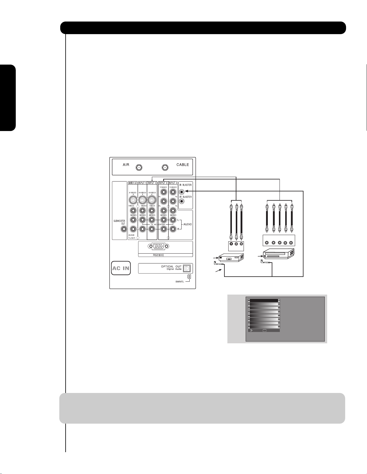
Your Hitachi Plasma Television is equipped with a G-LINK feature. This connection is necessary for the TV
Guide On Screen
TM
system to work with your cable box to receive program listings and to enable VCR
recording features. Once you setup the G-LINK (IR Mouse) connector, then you can use your HITACHI
Plasma TV Remote Control and the TV Guide On Screen system to control your cable box and VCR
recording features.
The Plasma Television Rear Panel has IR BLASTER/G-LINK jacks. One IR Mouse cable can connect up to
2 external Audio/Video components. Please see the following example of a G-LINK setup between your
HITACHI Plasma Television and external Audio/Video equipment (VCR and Cable box).
CONNECTING THE CABLE BOX/VCR TO G-LINK FOR TV GUIDE ON SCREEN
TM
SYSTEM
1. Connect your external Audio/Video components to the Rear Panel shown below.
2. Connect the IR Mouse cable to the IR BLASTER/G-LINK output of the Rear Panel.
3. Place the IR Mouse in front of the infrared sensor of the external components you want to control.
NOTE: 1. The G-LINK connection is not necessary for D-VHS recording devices.
2. The IR Mouse must be placed in front of the external components infrared sensor for the AV
Network to work.
3. G-LINK connections are available on both IR BLASTER jacks.
22
Connecting External Video Sources
First time use
4. To access the TV Guide On-ScreenTMsystem,
press the MENU button.
5. Use the CURSOR PAD or channel scroll down
to highlight TV GUIDE ON SCREEN.
6. Press the SELECT or CURSOR PAD button to
select.
7. Follow the Setup procedure on pages 49-53.
/
G-LINK
V L R
OUTPUT
Infrared
Sensor
Video
Audio
TV Guide On Screen
Channel Manager
Locks
Timers
Setup
Power Swivel
Move SEL Select
Infrared
Sensor
IR
Mouse
VCR
YP
Cable Box
OUTPUT
B/CBPR/CR
R L
23
The Remote Control
In addition to controlling all the functions on your
HITACHI Plasma TV, the new remote control is
designed to operate different types of VCRs, CATV
(Cable TV) converters, set-top-box, satellite
receiver, DVD players, and other audio/video
equipment with one touch. Basic operation keys
are grouped together in one area.
To operate your Plasma TV, point the remote
control at the remote sensor of the Television and
select the TV by pressing the or button of the
Source Access on the remote. The TV mode
indicator will blink, indicating that the remote will
now control your television.
To operate your VCR, point the remote at the
remote sensor of the VCR and select PVR by
pressing the or button of the Source Access
on the remote. The PVR mode indicator will blink,
indicating that the remote will now control your
VCR (see page 37 for instructions on how to
program the remote to control your VCR).
To operate your PVR (Personal Video Recorder),
point the remote at the remote sensor of the PVR
and select PVR by pressing the or button of
the Source Access on the remote. The PVR mode
indicator will blink, indicating that the remote will
now control your PVR (see page 37 for instruction
on how to program the remote to control your
PVR).
To operate your cable box, point the remote at the
remote sensor of the cable box and select the
CABLE (CBL) by pressing the or button of the
Source Access on the remote. The CBL mode
indicator will blink, indicating that the remote will
now control your cable box (see page 34 for
instructions on how to program the remote to
control your cable box).
To operate your set-top-box or satellite receiver
point the remote at the remote sensor of the settop-box and select the SET-TOP-BOX (STB) by
pressing the or button of the Source Access
on the remote. If you have a satellite receiver, use
this button to program your satellite receiver. The
STB mode indicator will blink, indicating that the
remote will now control your set-top-box (see
page 35 for instructions on how to program the
remote to control your set-top-box).
To operate your DVD player, point the remote at
the remote sensor of the DVD player and select
DVD by pressing the or button of the Source
Access on the remote. The DVD mode indicator
will blink, indicating that the remote will now
control your DVD Player (see page 36 for
instruction on how to program the remote to
control your DVD
player).
To operate additional audio equipment, point the
remote at the remote sensor of the component you
wish to control and select AMP by pressing the
or button of the Source Access on the remote.
The AMP mode indicator will blink, indicating that
the remote will now control your audio equipment
(see page 38 for instructions on how to program
the remote to control additional Audio/Video
equipment).
NOTE: When you press any remote control button,
the buttons will light up. The illumination will
light a few seconds during this time. The
buttons will appear to light if the room is
dark.
There are two modes of lighting the Remote Control buttons.
They are the Automatic and Manual modes.
AUTOMATIC MODE (Default mode)
In Automatic mode, if any button is pressed (including the
LIGHT button), the illumination will light for 4 seconds.
MANUAL MODE (Optional mode)
In Manual mode, the illumination will only work when the
LIGHT button is pressed. When the LIGHT button is pressed,
the illumination will light for 8 seconds. During the illumination, if the LIGHT button is pressed, the illumination will turn
off.
CHANGING LIGHTING MODES (Automatic to
Manual/Manual to Automatic)
1. Place the Remote Control in TV Mode by using the
SOURCE ACCESS
and buttons. The TV mode
indicator will blink 3 times to confirm the remote control
mode.
2. Press and hold the LIGHT button for 10 seconds. After
releasing the LIGHT button, the TV mode indicator will
blink 3 times to confirm the mode switch.
The Remote Control
A/V NET
/
24
The Remote Control
POWER button
Press this button to turn the TV set on or off when
the remote is in TV mode. (See page 23 for
instructions on how to set the remote control to TV
mode.)
MODE Indicator
Turns on or blinks to show remote control mode.
햴 SOURCE ACCESS ( or ) buttons
Press these buttons to select remote control mode.
SOURCE ACCESS (ENT) button
Hold down this button while entering your device
code to program the remote (see pages 34-41).
You can also use this button in an optional Input
access feature (see page 39).
PAUSE button
Press the PAUSE button to freeze the picture.
Press the EXIT button to return the picture to
motion. Press the PAUSE button repeatedly to
cycle through the three different freeze modes (see
page 33).
How to Use the Remote to Control Your TV
햴
/
Freeze
Freeze
Freeze
Freeze
Freeze
25
The Remote Control
How to Use the Remote to Control Your TV
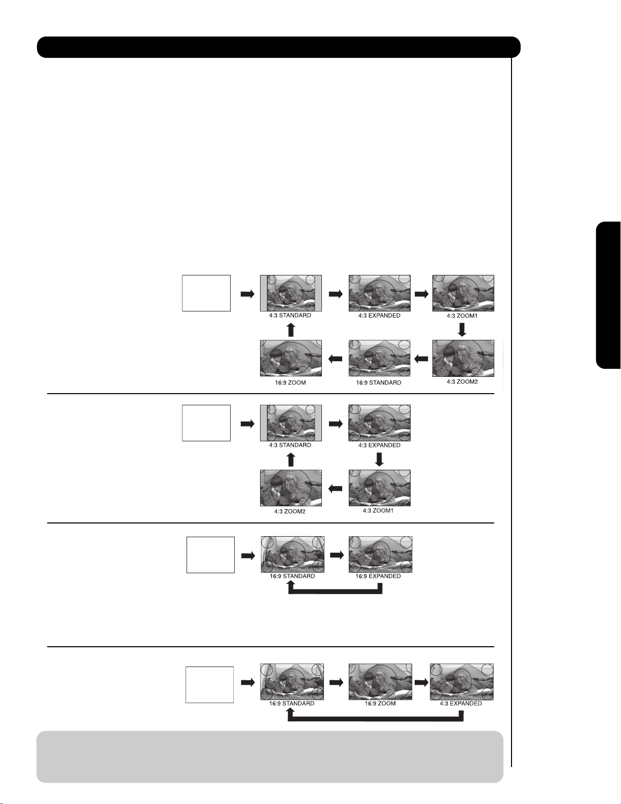
ASPECT button
Press this button to quickly change the picture format ASPECT ratio. Depending on the input signal format
received, the picture format ratio allows you to adjust the images through the following options.
• Antenna-Analog
• S-Video/Video Input
(Auto Aspect: Off)
• HDMI-480i/480p Input
(Auto Aspect: Off)
• Component-480i/480p
Input (Auto Aspect: Off)
Note: Please see Appendix A
on page 100.
• Antenna-Digital (4:3)
• S-Video/Video 4:3/Letter
Input (Auto Aspect: On)
• HDMI-480i/480p 4:3/
Letter Input (Auto Aspect: On)
• Component-480i/480p 4:3/
Letter Input
(Auto Aspect: On)
Note: Please see Appendix B
on page 100.
• S-Video/Video 16:9 Input
(Auto Aspect: On)
• HDMI-480i/480p 16:9 Input
(Auto Aspect: On)
• Component-480i/480p
16:9 Input
(Auto Aspect: On)
Note: Please see Appendix C
on page 100.
• Antenna-Digital (16:9)
• HDMI-720p/1080i Input
• Component-720p/1080i
Input
Note: Please see Appendix D
on page 100.
NOTE: 1. The Aspect Style setting you select for an ANT input will automatically be set for the other ANT
input. However, all five video inputs have independent Aspect Style settings.
2. Vertical position adjustments are directly available when you choose 4:3
EXPANDED/ZOOM1/ZOOM2 or 16:9 ZOOM aspect style (see also page 45).
4:3 STANDARD
Use this aspect mode to display conventional (4:3)
images. Side panels (gray areas) are placed to the
left and right of the image to preserve the original
aspect ratio of the source. Note: Use this mode for
only 15% of your total viewing time to prevent
uneven aging of the phosphors. Phosphors in the
lighted area of the picture will age more rapidly
than the gray areas.
4:3 EXPANDED
Use this aspect mode to display conventional (4:3)
sources by linearly increasing image expansion
from the center towards the edges of the display
area in order to fill it.
4:3 ZOOM1/ZOOM2
Use these aspect modes to zoom in on
conventional (4:3) sources.
16:9 STANDARD
Use this aspect mode to display 16:9 sources like
HDTV and DVD’s preserving the original 16:9
aspect ratio.
16:9 ZOOM
Use this aspect to Zoom-in once while in 16:9
aspect.
IMAGE INPUT
IMAGE INPUT
IMAGE INPUT
IMAGE INPUT
26
The Remote Control
DAY/NIGHT button
Press this button to toggle between Day and Night
picture mode settings. Select Day for day time
viewing with more brightness and contrast to
compete with room light. Select Night for night
time viewing with less brightness and contrast for a
more detailed picture (see page 44 for settings
changes).
NOTE: For automatic DAY/NIGHT picture mode
settings, see page 44.
PICTURE-IN-PICTURE button
See separate section on pages 31-33 for a
description.
MENU button
The MENU button will start the On-Screen Display.
INFO button
Press this button when you want to check the
channel being received, the picture source, if the
channel has stereo (ST) or second audio program
(SAP), the time, CHANNEL ID and if the TIMER is
set.
NOTE: 1. The Sleep Timer info will show
momentarily after releasing INFO button.
2. The Aspect setting will not be shown if
the channel is locked.
EXIT button
This button will exit all On-Screen Displays.
CURSOR PAD/SELECT button
All the On-Screen Display features can be set or
adjusted by using the CURSOR PAD, except for
numeric entries. The CURSOR PAD will highlight
functions or adjust and set different features. Press
the CURSOR PAD toward desired direction and
press the SELECT button to select.
GUIDE button
Press this button to access the TV Guide On
Screen
TM
interactive display (see page 54). Press
this button to access the Channel Guide of the
(CBL), and (SAT/STB) while in (CBL)(SAT/STB)
mode.
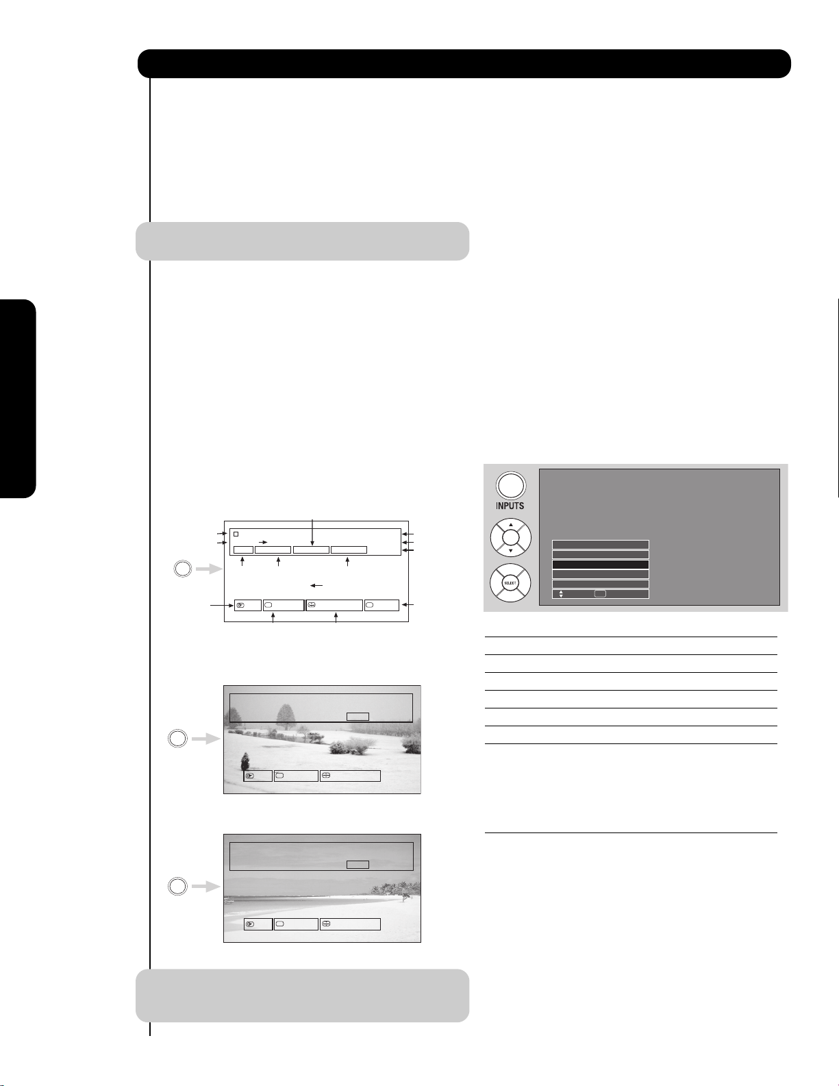
INPUTS button
When the remote control is in TV mode, press this
button to access the INPUTS menu. Use the
CURSOR PAD and SELECT button to select the
inputs that are being used. Pressing the INPUTS
button repeatedly will also cycle through the Inputs
menu items. Then press the SELECT button to
select.
INPUT 1 Select to choose INPUT 1.
INPUT 2 Select to choose INPUT 2.
INPUT 3 Select to choose INPUT 3.
INPUT 4 Select to choose INPUT 4.
INPUT 5 Select to choose INPUT 5.
CABLE Select to choose Cable.
AIR Select to choose Air.
PHOTO INPUT Select to access your pictures from a
digital camera, USB memory or
memory card USB drive connected to
the Photo Input in the side panel of
the Plasma TV (see pages 27-28).
IEEE1394 Select to choose the IEEE1394 Input
(see page 29).
How to Use the Remote to Control Your TV
ANALOG/DIGITAL CHANNELS
When an S-VIDEO Input is connected
to INPUT 3
When a Component Video: Y-PbPr
Input is connected to INPUT 1
Program Information
Program Run Time
INFO
Picture mode
Day/Night
setting
Sesame Street Air 15-2
9:30 AM 10:30 AM
ST TV-14 V
Audio
Broadcast
Telly and Baby Bears Story.
Day Off 16:9 Standard
Digital Closed
Caption. This icon
will appear only when
receiving a Digital Broadcast
with Closed Captioning.
DTv CC 1080i
Broadcast
Rating
CC
Closed
Caption setting
Picture Format
Program Desctiption
Aspect Mode
KPBS-DT
11:00PM
1:00AM
Main Picture Source
and channel indication
Broadcast channel
identification
Clock
Event Timer. This
Icon will appear
only after the
Event Timer in the
Timer Menu is
programmed.
Photo Input
IEEE 1394
Cable
Air
Input 1
Move SEL Sel.
INFO
480i
S-IN:3
11:00PM
CC
Day Off 4:3 Expanded
YPBPR:1
480i
INFO
11:00PM
CC
Day Off 4:3 Expanded
27
The Remote Control
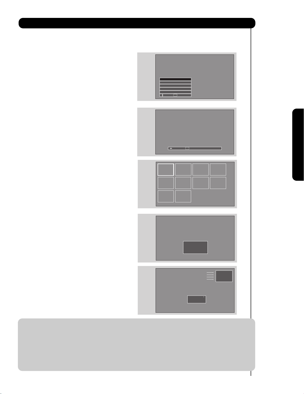
1. Press the INPUTS button to cycle through the
INPUTS selections until the PHOTO INPUT is
selected. Press the SELECT button or
CURSOR PAD .
2. Press the CURSOR PAD or to access the
next or previous photo.
3. Press the SELECT button to view
THUMBNAIL.
4. Use the CURSOR PAD buttons , , or
and the SELECT button to navigate and select
individual chosen photos.
5. Press the picture number to jump from picture
to picture.
6. Press the INFO button to access PHOTO Input
menu and to view Photo information.
7. Press the CURSOR PAD or and the
SELECT button to navigate and select the
PHOTO Input menu.
How to Use the Remote to Control Your TV
PHOTO INPUT
This feature is useful for viewing digital still pictures from your digital camera, USB Drive or memory cards USB
drive using the Photo Input in the left side panel of the TV.
Please Enter
Picture Number
--
No. 02/08
06/13/05
2048x1536
DSC00467
Rotate
Slideshow
Device
Picture No.
Date
Resolution
File Name
NOTES: 1. Contrast will decrease automatically if stationary images such as digital still photos are left
on the screen for more than 3 minutes.
2. The maximum number of digital Photos that can be displayed is 999.
3. Press INFO button to show Picture Numbers in Thumbnail view, plus other information in
individual photos.
4. Digital photos recorded on a DVD-RAM disc may not work with this Photo Input.
5. Certain types of digital cameras may not work with this Photo Input.
6. Digital cameras with low battery power may not properly display your photos in this input.
7. The screen may show “Input device not detected” if the digital camera’s large capacity
memory is fully loaded, or because of slow access time on some digital cameras. Please
wait 1 or 2 minutes before checking your Photo Input connections.
Photo Input
IEEE 1394
Cable
Air
Input 1
Move SEL Sel.
SEL Thumbnail [0-9] Jump
Next
28
The Remote Control
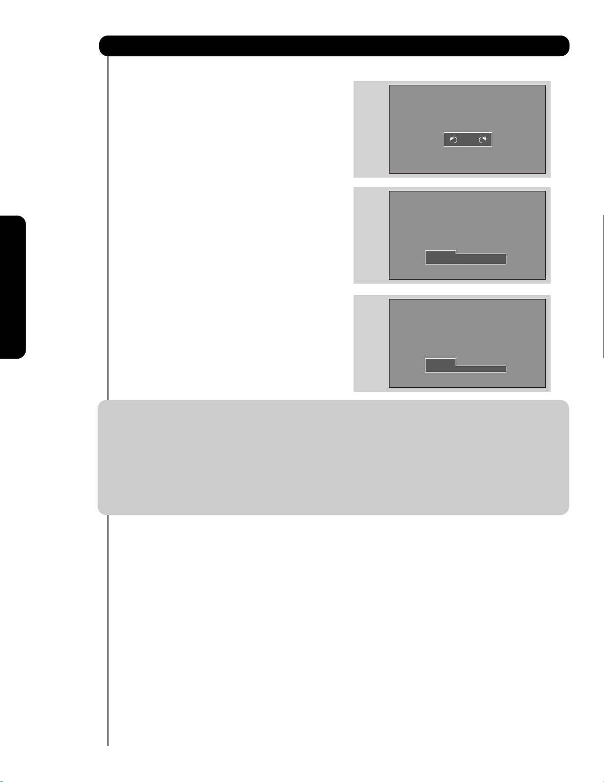
ROTATE
Select this menu item to rotate selected photos
either clockwise (CURSOR PAD ) and
counterclockwise (CURSOR PAD ).
SLIDESHOW
Select this menu item to start a slideshow of the
digital photos. While the Interval sub menu is
highlighted, press the SELECT button to cycle
through the interval time from 5, 10 and 30 seconds.
Press the SELECT button to stop on a chosen
picture of the slideshow. After 30 seconds, the
slideshow will resume or press the SELECT button
again to continue with the slideshow.
DEVICE
Select this menu item to select the Photo Input
Device Drive when using a USB Drive device. Use
the CURSOR PAD or to select Device Drive.
Press the INFO button to highlight a device, then
press the SELECT button or CURSOR PAD to
access it. Use the CURSOR PAD or to choose
the device to read.
How to Use the Remote to Control Your TV
NOTES: 1. Automatic contrast reduction also applies during SLIDESHOW, then press any button to
continue.
2. Photo file names modified on a computer should be 8 characters (Ex. ABCD1234.jpg). 1st
character: letters; 2nd to 4th: letters or numbers; 5th to 8th: numbers. Photo files should be
first placed on a sub directory name with 8 characters (Ex. 123ABCDE). 1st to 3rd: number;
4th to 8th: letters. The sub directory then should be placed on a main directory with a
“dcim” file name format.
3. Supported image types are up to 3072 x 2304; JPEG format should conform with DCF
Standard (Design rule for Camera File System).
4. This TV set displays only digital pictures from digital cameras which meet DCF Standard.
Pictures that were copied, edited or modified on a computer may not be displayed on the TV
set.
Rotate
Slideshow Start
Device Interval 30sec
Rotate
Slideshow
Device Drive B
29
How to Use the Remote to Control Your TV
The Remote Control
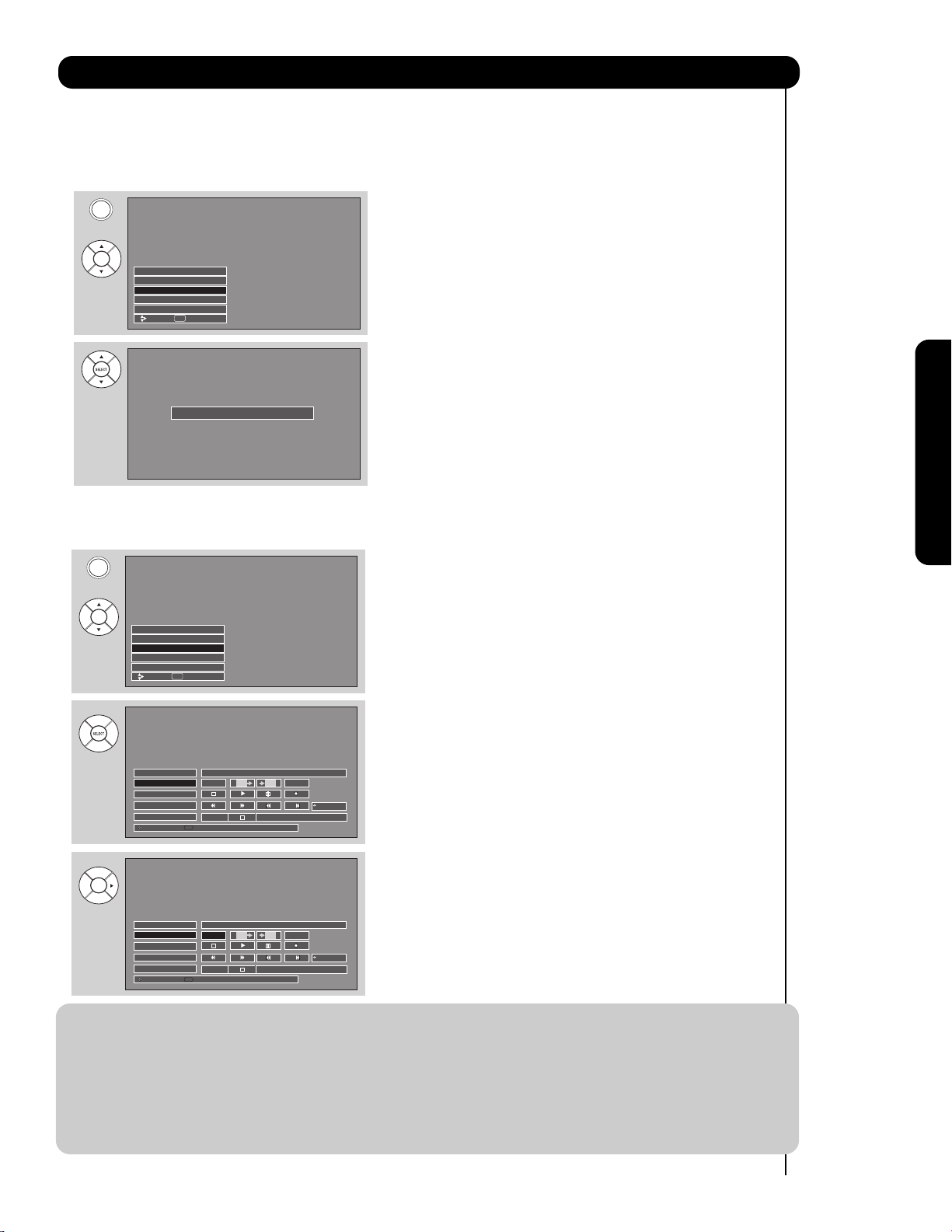
When an IEEE1394 device is not connected
When an IEEE1394 device is connected
1. Press INPUT button, CURSOR PAD and SELECT
button to select IEEE 1394.
2. Use CURSOR PAD to select connected device
(example D-VHS1).
3. Use CURSOR PAD cursors to highlight POWER.
4. Press the SELECT button to power on the device.
5. Use CURSOR PAD cursors to select D-VHS
operation.
6. Press down on the CURSOR PAD to enable the
selected operation.
7. Use CURSOR PAD cursors to highlight the TV
IN/OUT operation.
8. Press the SELECT button to select:
TV IN is DVHS
TV OUT is Cable
IEEE1394
Use this function to control your devices with digital interface capabilities.
NOTES: 1. The digital device will be automatically recognized if properly connected.
2. Four (4) IEEE1394 devices can be listed on the menu, but only one device at a time can be
used. If a fifth device is connected, it will replace the first device on the menu list.
3. The On-Screen display will not disappear until the EXIT button is pressed.
4. Not all devices with IEEE1394 capability are compatible with this TV. Any compatibility
problems with other manufacturers devices should be brought to the attention of those
manufacturers.
5. TV IN/OUT functions are not available when D-VHS is in playback or recording.
6. Digital channels may contain Copy Control Information (CCI). When using a CableCARD,
this CCI data will prevent recording of some programs depending on its content value.
INPUTS
Photo Input
IEEE 1394
Cable
Air
Input 1
Move SEL Sel.
Device not detected
INPUTS
Input 5
Photo Input
IEEE 1394
Cable
Air
Move SEL Sel.
IEEE1394 DEVICE NAME, BRAND NAME
DVHS1
Move
IEEE1394 DEVICE NAME, BRAND NAME
DVHS1
Move
POWER RESET
TV
STD Counter:-00:03:31
SEL
Select
TV
STD Counter:-00:03:31
SEL
Select
TV
00:00:00
RESETPOWER
TV
00:00:00
The Remote Control
30
LAST CHANNEL (LAST CH) button
Press this button to toggle between the current and
last channel viewed.
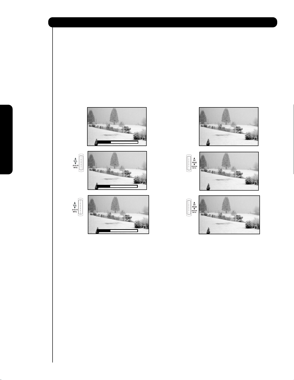
VOLUME (VOL) WHEEL, MUTE button
Use the VOL WHEEL ( or ) until you obtain the
desired sound level.
To reduce the sound to one half of normal volume
(SOFT MUTE) to answer the telephone, etc., press
the VOL wheel down. Press the VOL wheel again
to turn the sound off completely (MUTE). To
restore the sound, press the VOL wheel one more
time or VOL Up ().
Closed Captioning will display automatically when
MUTE/SOFT MUTE is on and Closed Caption is set
to AUTO (see page 88).
When the TV power is turned off at a volume level
31 or greater, the volume level will default to 30
when the TV is turned on. However, if it is set to a
level 30 or less, the volume level will be at the level
it was set when the TV is turned ON.
CHANNEL (CH) WHEEL/CHANNEL SELECTOR
buttons
The CHANNEL wheel or the CHANNEL SELECTOR
buttons are used to select channels, lock access
code, etc. Use the CHANNEL WHEEL ( or ) to
select the desired channel. Use the CHANNEL
SELECTOR buttons to enter one, two, or three
numbers to select channels. Enter “0” first for
channels 1 to 9, or simply press the single digit
channel you wish to tune then wait a few seconds
for the TV to tune. For Digital Channels, use the
CHANNEL SELECTOR buttons with the (-) DASH
button. Channel selection may also be performed
by CHANNEL WHEEL up () or CHANNEL WHEEL
down ().
Press the channel (CH) wheel to switch to Favorite
(FAV) channel mode. You will know you are in
Favorite Channel mode when (FAV) is displayed
and the displayed channel is GREEN. Press it
again to return to your regular tuned channels. You
can add any channel to your Favorite channel list
by pressing and holding down the Channel (CH)
wheel until the displayed channel turns from WHITE
to highlighted GREEN. You can also delete a
channel from your favorite channel list by pressing
and holding down the Channel (CH) wheel until the
displayed channel turns highlighted GREEN to
WHITE.
(-) DASH button
Use the (-) DASH button with the CHANNEL
SELECTOR buttons to enter Digital Channels that
have subchannel numbers indicated by (-) DASH
(example 15-1).
BACKLIGHT button
Press this button to light up and illuminate the
buttons of the remote control.
How to Use the Remote to Control Your TV
Volume 8
Soft Mute 8
Cable 22
Cable 22
Mute 8
Cable 22
/
/
 Loading...