

HITACHI 42HDT51M, 55HDT51M Service Manual

PA
Updated 5/23/05
Version 0187.2
Updated 8/11/05
No. 0187
42HDT51M: PT5-G Chassis
55HDT51M: PW1-H Chassis
SERVICE MANUAL
NN TT SS CC
AVC75: AVC5-U Chassis
PPTT55--GG//PPWW11--HH
R/C: CLU-3841WL
AAVVCC55--UU CChhaassssiiss
TO GO TO A CHAPTER, CLICK ON ITS HEADING BELOW
CONTENTS
SAFETY PRECAUTIONS . . . . . . . . . . . . . . . . . . . . . . . . . . . . . . . . . . . . . . . . . . . . . . . . . 2
PRODUCT SAFETY NOTICE . . . . . . . . . . . . . . . . . . . . . . . . . . . . . . . . . . . . . . . . . . . . . .3
SERVICING PRECAUTIONS . . . . . . . . . . . . . . . . . . . . . . . . . . . . . . . . . . . . . . . . . . . . . .4
AGENCY REGULATORY INFORMATION . . . . . . . . . . . . . . . . . . . . . . . . . . . . . . . . . . . . .9
ACKNOWLEDGMENTS AND TRADEMARKS . . . . . . . . . . . . . . . . . . . . . . . . . . . . . . . .10
INTRODUCTION . . . . . . . . . . . . . . . . . . . . . . . . . . . . . . . . . . . . . . . . . . . . . . . . . . . . . . .11
SPECIFICATIONS . . . . . . . . . . . . . . . . . . . . . . . . . . . . . . . . . . . . . . . . . . . . . . . . . . . . . .12
BASIC SETUP & OPERATION . . . . . . . . . . . . . . . . . . . . . . . . . . . . . . . . . . . . . . . . . . . .15
ADJUSTMENTS . . . . . . . . . . . . . . . . . . . . . . . . . . . . . . . . . . . . . . . . . . . . . . . . . . . . . . .24
TROUBLESHOOTING FLOWCHARTS . . . . . . . . . . . . . . . . . . . . . . . . . . . . . . . . . . . . . .48
BLOCK DIAGRAMS . . . . . . . . . . . . . . . . . . . . . . . . . . . . . . . . . . . . . . . . . . . . . . . . . . . . .53
CONNECTION DIAGRAMS . . . . . . . . . . . . . . . . . . . . . . . . . . . . . . . . . . . . . . . . . . . . . . .62
FINAL WIRING DIAGRAM . . . . . . . . . . . . . . . . . . . . . . . . . . . . . . . . . . . . . . . . . . . . . . . .63
EXPLODED VIEW (AVC) . . . . . . . . . . . . . . . . . . . . . . . . . . . . . . . . . . . . . . . . . . . . . . . . .68
WAVEEFORMS . . . . . . . . . . . . . . . . . . . . . . . . . . . . . . . . . . . . . . . . . . . . . . . . . . . . . . . .69
DC VOLTAGES . . . . . . . . . . . . . . . . . . . . . . . . . . . . . . . . . . . . . . . . . . . . . . . . . . . . . . . ..70
CIRCUIT SCHEMATIC DIAGRAMS . . . . . . . . . . . . . . . . . . . . . . . . . . . . . . . . . . . . . . . .78
PRINTED CIRCUIT BOARDS . . . . . . . . . . . . . . . . . . . . . . . . . . . . . . . . . . . . . . . . . . . . .95
EXPLODED VIEW (PDP MONITOR) . . . . . . . . . . . . . . . . . . . . . . . . . . . . . . . . . . . . . .107
PARTS LIST . . . . . . . . . . . . . . . . . . . . . . . . . . . . . . . . . . . . . . . . . . . . . . . . . . . . . . . . . .109
QUICK REFERENCE PARTS LIST . . . . . . . . . . . . . . . . . . . . . . . . . . . . . . . . . . . . . . . .130
CAUTION: These servicing instructions are for use by qualified service personnel only. To reduce the risk of
electric shock do not perform any servicing other than that contained in the operating instructions
unless you are qualified to do so. Before servicing this chassis, it is important that the service
technician read the “IMPORTANT SAFETY INSTRUCTIONS” in this service manual.
SAFETY NO
USE ISOLATION TRANSFORMER WHEN SERVICING
Components ha
vice Data and its supplements and b
Ser
read and follow the “Important Safety Instructions” in this Service Manual.
ving special saf
ety char
acteristics are identified by a on the schematics and on the parts list in this
ore ser
Bef
ulletins
.
TICE
!
vicing the chassis
, it is important that the service technician
SPECIFICATIONS AND PARTS ARE SUBJECT TO CHANGE FOR IMPROVEMENT
PLASMA DISPLAY PANEL
JUNE 2004 HHEA-MANUFACTURING DIVISION
SAFETY PRECAUTIONS
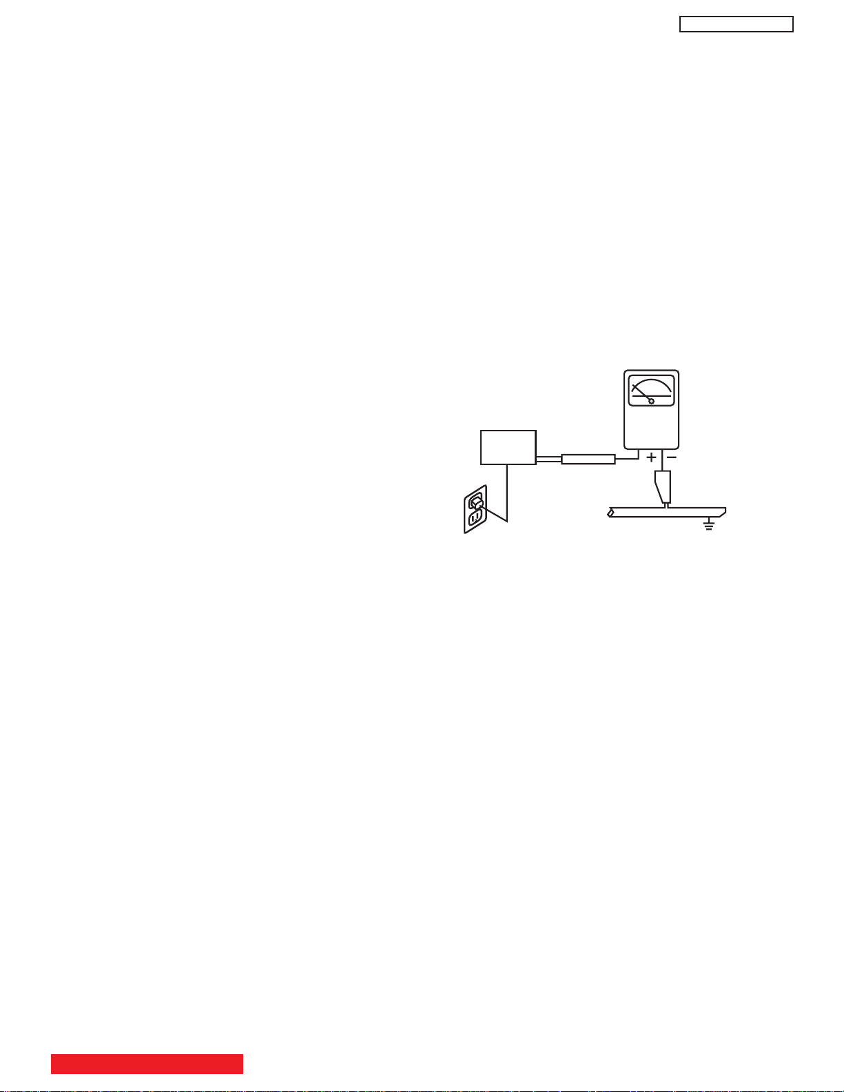
LEAKAGE
CURRENT
TESTER
(READING
SHOULD NOT
BE ABOVE 0.5MIU)
EARTH
GROUND
TEST ALL
EXPOSED
METAL SURFACES
DEVICE
UNDER
TEST
3-WIRE CORD
ALSO TEST WITH PLUG
REVERSED
(USING AC ADAPTER
PLUS AS REQUIRED)
NOTICE: Comply with all cautions and safety-related notes
located on or inside the cover case and on the chassis or plasma
module.
WARNING: Since the chassis of the AVC unit and Plasma Panel
unit is connected to both sides of the AC power supply during
operation, whenever the receiver is plugged in, service should
not be attempted by anyone unfamiliar with the precautions
necessary when working on this type of receiver.
1. When service is required, an isolation transformer should be
inserted between power line and the receiver before any
service is performed on a “HOT” chassis receiver.
2. When replacing a chassis in the receiver, all the protective
devices must be put back in place, such as barriers, nonmetallic knobs, insulating cover-shields, and isolation
resistors, capacitors, etc.
3. When service is required, observe the original lead dress.
4. Always use manufacturer’s replacement components. Critical
components as indicated on the circuit diagram should not be
replaced by another manufacturer’s. Furthermore, where a
short circuit has occurred, replace those components that
indicate evidence of over heating.
PT5-G/PW1-H
Leakage Current Hot Check
This check must be done considering the AVC or the PDP
monitor as one instrument each.
With any of the instruments completely reassembled (being
the instrument either the AVC center or the PDP monitor), plug
the AC line cord directly into a 120V AC outlet. (Do not use an
isolation transformer during this test.) Use a leakage current
tester or a metering system that complies with the American
National Standards Institute (ANSI) C101.0 Leakage Current
for Appliances. In the case of the PDP monitor set the AC
switch first in the ON position and then in the OFF position,
measure from across Line 1 and Line 2 of the three plug
prongs, do not connect with the third prong, which is physical
ground, to all exposed metal parts of the instrument
(antennas, handle bracket, metal cabinet, screw heads,
metallic overlays, control shafts, etc.), especially any exposed
metal parts that offer an electrical return path to the chassis.
Any current measured must not exceed 0.5 MIU. Reverse the
instrument power cord plug in the outlet and repeat test.
AC LEAKAGE TEST
5. Before returning a serviced receiver to the customer, the
service technician must thoroughly test the unit to be certain
that it is completely safe to operate without danger of electrical
shock, and be sure that no protective device built into the
receiver by the manufacturer has become defective, or
inadvertently defeated during servicing.
Therefore, the following checks should be performed for the
continued protection of the customer and service technician.
Leakage Current Cold Check
With the AC plug removed from the 120V AC 60Hz source,
place a jumper across Line 1 and Line 2 of the three plug
prongs, do not connect with the third prong, which is physical
ground.
Using an insulation tester (DC500V), connect one of its leads
to the AC plug jumper and touch with the other lead each
exposed metal part (antennas, screwheads, metal overlays,
control shafts, etc.), particularly any exposed metal part
having a return path to the chassis should have a resistor
reading over 4MΩ. Any resistance value below this range
indicates an abnormality which requires corrective action. An
exposed metal part not having a return path to the chassis will
indicate an open circuit.
ANY MEASUREMENTS NOT WITHIN THE LIMITS OUTLINED
ABOVE ARE INDICATIVE OF A POTENTIAL SHOCK HAZARD
AND MUST BE CORRECTED BEFORE RETURNING THE
RECEIVER TO THE CUSTOMER.
TABLE OF CONTENTS
2

PRODUCT SAFETY NOTICE
Many electrical and mechanical parts in HITACHI television
receivers have special safety-related characteristics. These are
often not evident from visual inspection nor can the protection
afforded by them necessarily be obtained by using replacement
components rated for higher voltage, wattage, etc. Replacement
parts which have these special safety characteristics are
identified in this Service Manual.
Electrical components having such features are identified with a
!
1 mark in the schematics and parts list in this Service Manual.
The use of a substitute replacement component which does not
have the same safety characteristics as the HITACHIrecommended replacement component, shown in the parts list in
this Service Manual, may create shock, fire, X-radiation, or other
hazards.
Product safety is continuously under review and new instructions
are issued from time to time. For the latest information, always
consult the current HITACHI Service Manual. A subscription to,
or additional copies of HITACHI Service Manuals may be
obtained at a nominal charge from HITACHI Sales Corporation.
AVC75 - Audio Video Control Unit
PT5-G/PW1-H
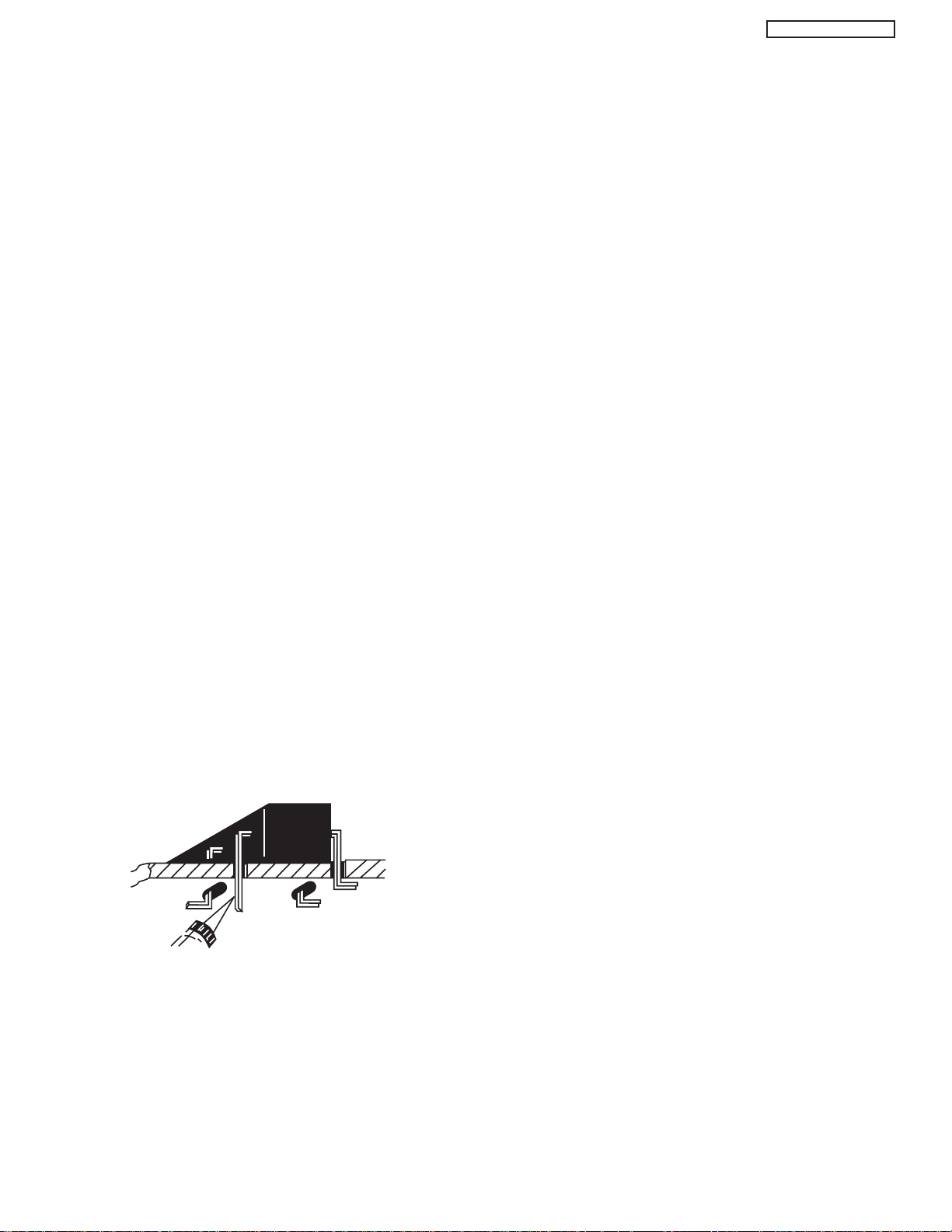
PDP Module Handling
When there is need to replace a broken PDP module which is the
displaying device from the Plasma monitor unit, consider the
following:
1. When carrying the PDP module, two persons should stand at
both shorter-edge sides of the glass-panel and transport it with
their palms. Avoid touching the Flexible Printed Circuits or the
chip tube on the corner of the glass-panel. Handle only by the
surface of the glass panel. In case of some PDP modules,
electrode repair is done by connecting between regular
terminal with Cu tape and Cu wire. Please do not hook and/or
damage this repair line. If it is damaged, the module will not
function unless the glass-panel is exchanged with a new
glass-panel.
2. When carrying PDP module, watch surrounding objects, such
as tables, and also do not carry it alone since it may be
dangerous and it will be damaged due to excessive stress to
the module (glass-panel).
3. Please do not stand the module with the edge of the glasspanel on the table since this might result in damage to the
glass-panel and/or flexible printed circuits due to excessive
stress to the module (glass-panel).
1. Follow the general caution recommendations from “Safety
precautions” section.
42HDT51M - Plasma Monitor Unit
55HDT51M - Plasma Monitor Unit
1. Follow the general caution recommendations from “Safety
precautions” section.
2. Since the Panel module and front filter are made of glass,
sufficient care shall be taken when handling the broken
module and filter in order to avoid injury.
3. If necessary to replace Panel module, this work must be
started after the panel module and the AC/DC Power supply
becomes sufficiently cool.
4. Special care must be taken with the display area to avoid
damaging its surface.
5. The Panel Module shall not be touched with bare hands to
protect its surface from stains.
6. It is recommended to use clean soft gloves during the
replacing work of the Panel module in order to protect, not
only the display area of the panel module but also the
serviceman.
7. The Chip Tube of the panel module (located upper left of the
back of the panel module) and flexible cables connecting
Panel glasses to the drive circuitry Printed Wiring Boards
(P.W.B.) are very weak, so sufficient care must be taken to
prevent breaking or cutting any of these. If the Chip Tube
breaks the panel module will never work, replacement for a
new plasma panel module will be needed.
8. Signal, power supply P.W.B.’s and PDP driving circuits
P.W.B.’s are assembled on the rear side of the PDP module,
take special care with this fragile circuitry; particularly, Flexible
Printed Circuits bonded to surrounding edges of the glass
panel. They are not strong enough to withstand harsh outer
mechanical forces. Avoid touching the flexible printed circuits
by not only your hands, but also tools, chassis, or any other
object. Extreme bending of the connectors must be avoided
too. In case the flexible printed circuits are damaged, the
corresponding addressed portions of the screen will not be lit
and exchange of a glass panel will be required.
WARNING
Lead in solder used in this product is listed by the California
Health and Welfare agency as a known reproductive toxicant
which may cause birth defects or other reproductive harm
(California Health and Safety Code, Section 25249.5).
When servicing or handling circuit boards and other components
which contain lead in solder, avoid unprotected skin contact with
solder. Also, when soldering make sure you are in a well
ventilated area in order to avoid inhalation of any smoke or
fumes released.
SAFETY NOTICE
USE ISOLATION TRANSFORMER
WHEN SERVICING
POWER SOURCE
This plasma television and the AVC Center is designed to
operate on 120 Volts/60Hz, AC house current. Insert the power
cord into a 120 Volts/60Hz outlet.
NEVER CONNECT THE PLASMA AND THE AVC CENTER TO
OTHER THAN THE SPECIFIED VOLTAGE OR TO DIRECT
CURRENT AND TO 50HZ. TO PREVENT ELECTRIC SHOCK,
DO NOT USE THE PLASMA TELEVISION’S (POLARIZED)
PLUG WITH AN EXTENSION CORD, RECEPTACLE, OR THE
OUTLETS UNLESS THE BLADES AND GROUND TERMINAL
CAN BE FULLY UNSERTED TO PREVENT BLADE
EXPOSURE.
TABLE OF CONTENTS
3

SERVICING PRECAUTIONS
CAUTION: Before servicing instruments covered by this
service data and its supplements and addenda, read and
follow the “Important Safety Instructions” on page 3 of this
publication.
NOTE: If unforeseen circumstances create conflict between
the following servicing precautions and any of the safety
precautions on page 3 of this publication, always follow the
safety precautions. Remember: Safety First.
PT5-G/PW1-H
Electrostatically Sensitive (ES) Devices
Some semiconductor (solid state) devices can be damaged
easily by static electricity. Such components commonly are
called Electrostatically Sensitive (ES) Devices. Examples of
typical ES devices are integrated circuits and some fieldeffect transistors and semiconductor “chip” components. The
following techniques should be used to help reduce the
incidence of component damage caused by static electricity.
General Servicing Guidelines
1. Always unplug the instrument AC power cord from the AC
power source before:
a. Removing or reinstalling any component, circuit
board, module, or any other instrument assembly.
b. Disconnecting or reconnecting any instrument
electrical plug or other electrical connection.
c. Connecting a test substitute in parallel with an
electrolytic capacitor in the instrument.
CAUTION: A wrong part substitution or incorrect
polarity installation of electrolytic
capacitors may result in an explosion
hazard.
2. Do not spray chemicals on or near this instrument or any
of its assemblies.
3. Unless specified otherwise in these service data, clean
electrical contacts by applying the following mixture to the
contacts with a pipe cleaner, cotton-tipped stick or
comparable nonabrasive applicator: 10% (by volume)
Acetone and 90% (by volume) isopropyl alcohol (90%99% strength).
CAUTION: This is a flammable mixture. Unless
specified otherwise in these service data,
lubrication of contacts is not required.
4. Do not defeat any plug/socket of voltage interlocks with
which instruments covered by this service data might be
equipped.
5. Do not apply AC power to this instrument and/or any of its
electrical assemblies unless all solid-state device heatsinks are correctly installed.
6. Always connect the test instrument ground lead to the
appropriate instrument chassis ground before connecting
the test instrument positive lead. Always remove the test
instrument ground lead last.
7. Use with this instrument only the test fixtures specified in
this service data.
CAUTION: Do not connect the test fixture ground strap
to any heatsink in this instrument.
1. Immediately before handling any semiconductor
component or semiconductor-equipped assembly, drain
off any electrostatic charge on your body by touching a
known earth ground. Alternatively, obtain and wear a
commercially available discharging wrist strap device,
which should be removed for potential shock reasons
prior to applying power to the unit under test.
2. After removing an electrical assembly equipped with ES
devices, place the assembly on a conductive surface
such as aluminum foil, to prevent electrostatic charge
buildup or exposure of the assembly.
3. Use only a grounded-tip soldering iron to solder or
desolder ES devices.
4. Use only an anti-static type solder removal device. Some
solder removal devices not classified as “anti-static” can
generate electrical charges sufficient to damage ES
device.
5. Do not use freon-propelled chemicals. These can
generate electrical charges sufficient to damage ES
devices.
6. Do not remove a replacement ES device from its
protective package until immediately before you are
ready to install it. (Most replacement ES devices are
packaged with leads electrically shorted together by
conductive foam, aluminum foil or comparable conductive
material.)
7. Immediately before removing the protective material from
the leads of a replacement ES device, touch the
protective material to the chassis or circuit assembly into
which the device will be installed.
CAUTION: Be sure no power is applied to the chassis or
circuit, and observe all other safety
precautions.
8. Minimize bodily motions when handling unpackaged
replacement ES devices. (Otherwise harmless motion
such as the brushing together of your clothes fabric or the
lifting of your foot from a carpeted floor can generate
static electricity sufficient to damage an ES device.)
TABLE OF CONTENTS
4
PT5-G/PW1-H
Use Soldering Iron to Pry Leads
General Soldering Guidelines
1. Use a grounded-tip, low-wattage soldering iron and
appropriate tip size and shape that will maintain tip
temperature within the range 500°F to 600°F.
2. Use an appropriate lead free solder (see page 8). Lead
solder can be used, but there is a possibility of failure due
to insufficient strength of the solder.
3. Keep the soldering iron tip clean and well-tinned.
4. Thoroughly clean the surfaces to be soldered. Use a
small wire-bristle (0.5 inch or 1.25 cm) brush with a metal
handle. Do not use freon-propelled spray-on cleaners.
5. Use the following desoldering technique.
a. Allow the soldering iron tip to reach normal
temperature (500°F to 600°F).
b. Heat the component lead until the solder melts.
Quickly draw away the melted solder with an antistatic, suction-type solder removal device or with
solder braid.
CAUTION: Work quickly to avoid overheating the
circuit board printed foil.
6. Use the following soldering technique.
a. Allow the soldering iron tip to reach normal
temperature (500°F to 600°F).
b. First, hold the soldering iron tip and solder strand
against the component lead until the solder melts.
c. Quickly move the soldering iron tip to the junction of
the component lead and the printed circuit foil, and
hold it there only until the solder flows onto and
around both the component lead and the foil.
CAUTION: Work quickly to avoid overheating the
circuit board printed foil or components.
Removal
1. Desolder and straighten each IC lead in one operation by
gently prying up on the lead with the soldering iron tip as
the solder melts.
2. Draw away the melted solder with an anti-static suctiontype solder removal device (or with solder braid) before
removing the IC.
Replacement
1. Carefully insert the replacement IC in the circuit board.
2. Carefully bend each IC lead against the circuit foil pad
and solder it.
3. Clean the soldered areas with a small wire-bristle brush.
(It is not necessary to reapply acrylic coating to areas.)
“Small-signal” Discrete Transistor Removal/Replacement
1. Remove the defective transistor by clipping its leads as
close as possible to the component body.
2. Bend into a “U” shape the end of each of the three leads
remaining on the circuit board.
3. Bend into a “U” shape the replacement transistor leads.
4. Connect the replacement transistor leads to the
corresponding leads extending from the circuit board and
crimp the “U” with long nose pliers to insure metal to
metal contact, then solder each connection.
Power Output Transistor Devices Removal/Replacements
1. Heat and remove all solder from around the transistor
leads.
2. Remove the heatsink mounting screw (if so equipped).
3. Carefully remove the transistor from the circuit board.
d. Closely inspect the solder area and remove any
excess or splashed solder with a small wire-bristle
brush.
IC Removal/Replacement
Some Hitachi unitized chassis circuit boards have slotted
holes (oblong) through which the IC leads are inserted and
then bent flat against the circuit foil. When holes are the
slotted type, the following technique should be used to
remove and replace the IC. When working with boards using
the familiar round hole, use the standard technique as
outlined in paragraphs 5 and 6 above.
4. Insert new transistor in circuit board.
5. Solder each transistor lead, and clip off excess lead.
6. Replace heatsink.
Diode Removal/Replacement
1. Remove defective diode by clipping its leads as close as
possible to diode body.
2. Bend the two remaining leads perpendicularly to the
circuit board.
3. Observing diode polarity, wrap each lead of the new
diode around the corresponding lead on the circuit board.
4. Securely crimp each connection and solder it.
5. Inspect (on the circuit board copper side) the solder joints
of the two “original leads”. If they are not shiny, reheat
them and, if necessary, apply additional solder.
5
PT5-G/PW1-H
CRIMP AND
SOLDER
BARE JUMPER
WIRE
Install Jumper Wire and Solder
DEFECTIVE
COPPER
REMOVED
Insulated Jumper Wire
Fuses and Conventional Resistor Removal/Replacement
1. Clip each fuse or resistor lead at top of circuit board
hollow stake.
2. Securely crimp leads of replacement component around
stake 1/8 inch from top.
3. Solder the connections.
CAUTION: Maintain original spacing between the
replaced component and adjacent
components and the circuit board, to
prevent excessive component
temperatures.
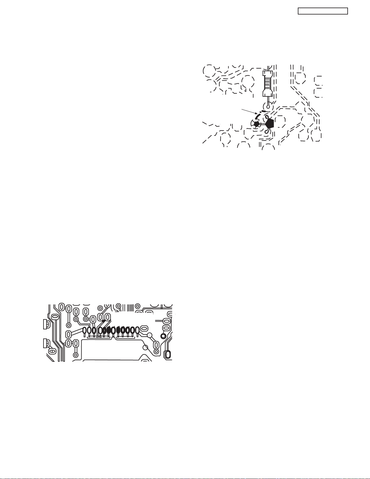
Circuit Board Foil Repair
Excessive heat applied to the copper foil of any printed
circuit board will weaken the adhesive that bonds the foil to
the circuit board, causing the foil to separate from, or “liftoff,” the board. The following guidelines and procedures
should be followed whenever this condition is encountered.
In Critical Copper Pattern Areas
High component/copper pattern density and/or special
voltage/current characteristics make the spacing and
integrity of copper pattern in some circuit board areas more
critical than in others. The circuit foil in these areas is
designated as Critical Copper Pattern. Because Critical
Copper Pattern requires special soldering techniques to
ensure the maintenance of reliability and safety standards,
contact your Hitachi personnel.
At Other Connections
Use the following technique to repair defective copper
pattern at connections other than IC Pins. This technique
involves the installation of a jumper wire on the component
side of the circuit board.
1. Remove the defective copper pattern with a sharp knife.
Remove at least 1/4 inch of copper, to ensure hazardous
condition will not exist if the jumper wire opens.
2. Trace along the copper pattern from both wire sides of
the pattern break and locate the nearest component
directly connected to the affected copper pattern.
At IC Connections
To repair defective copper pattern at IC connections, use the
following procedure to install a jumper wire on the copper
pattern side of the circuit board. (Use this technique only on
IC connections.)
1. Carefully remove the damaged copper pattern with a
sharp knife. (Remove only as much copper as absolutely
necessary.)
2. Carefully scratch away the solder resist and acrylic
coating (if used) from the end of the remaining copper
pattern.
3. Bend a small “U” in one end of a small-gauge jumper wire
and carefully crimp it around the IC pin. Solder the IC
connection.
4. Route the jumper wire along the path of the cut-away
copper pattern and let it overlap the previously scraped
end of the good copper pattern. Solder the overlapped
area, and clip off any excess jumper wire.
3. Connect insulated 20-gauge jumper wire from the
nearest component on one side of the pattern break to
the lead of the nearest component on the other side.
Carefully crimp and solder the connections.
CAUTION: Be sure the insulated jumper wire is
dressed so that it does not touch
components or sharp edges.
6
PT5-G/PW1-H
NOTE: These components are affixed with glue. Be careful not to break or damage any foil under the
component or at the pins of the ICs when removing. Usually applying heat to the component for a short
time while twisting with tweezers will break the component loose.
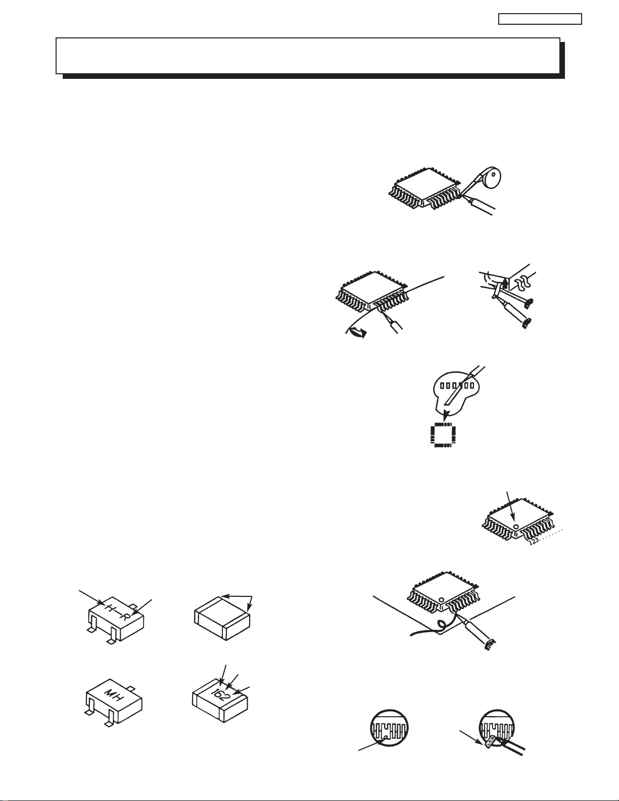
Leadless Chip Components
(surface mount)
Chip components must be replaced with identical
chips due to critical foil track spacing. There are no
holes in the board to mount standard transistors or
diodes. Some chip capacitor or resistor board solder
pads may have holes through the board, however the
hole diameter limits standard resistor replacement to
1/8 watt. Standard capacitors may also be limited for
the same reason. It is recommended that identical
chip components be used. .
Chip resistors have a three digit numerical resistance
code -1st and 2nd significant digits and a multiplier.
Example: 162 = 1600 or 1.6KΩ resistor, 0 = 0Ω
(jumper).
Chip capacitors generally do not have the value
indicated on the capacitor. The color of the component
indicates the general range of the capacitance.
Chip transistors are identified by a two letter code. The
first letter indicates the type and the second letter, the
grade of transistor.
Chip diodes have a two letter identification code as
per the code chart and are a dual diode pack with
either
common anode or common cathode. Check the parts
list for correct diode number.
Component Removal
1. Use solder wick to remove solder from component
end caps or terminals.
2. Without pulling up, carefully twist the component
with tweezers to break the adhesive.
3. Do not reuse removed leadless or chip
components since they are subject to stress
fracture during removal .
Chip Component Installation
1. Put a small amount of solder on the board
soldering pads.
2. Hold the chip component against the soldering
pads with tweezers or with a miniature alligator
clip and apply heat to the pad area with a 30 watt
iron until solder flows. Do not apply heat for more
than 3 seconds
TYPE
Chip Components
C
GRADE
SOLDER
CAPS
How to Replace Flat-lC
—Required Tools—
• Soldering iron • iron wire or small awl
• De-solder braids • Magnifier
1. Remove the solder from all of the pins of a Flat-lC
by using a de-solder braid.
De-Solder
Braid
Soldering
Iron
2. Put the iron wire under the pins of the Flat-lC and
pull it in the direction indicated while heating the
pins using a soldering iron. A small awl can be
used instead of the iron wire.
Pull
Soldering
Iron
3. Remove the solder from all of the pads of the
Fiat-lC by using
a de-solder braid.
4. Position the new Flat-lC in place (apply the pins of
the Flat-lC to the soldering pads where the pins
need to be soldered). Properly
determine the positions of the
soldering pads and pins by
correctly aligning the polarity
symbol.
5. Solder all pins to the soldering pads using a fine
tipped soldering iron.
Iron
Wire
Awl
Soldering
Iron
Soldering
Iron
De-Solder
Braid
Flat-IC
Polarity Symbol
B
ANODES
E
COMMON CATHODE
MH DIODE
TRANSISTOR
SOLDER CAPS
1ST DIGIT
RESISTOR
CAPACITOR
2ND DIGIT
MULTIPLIER
= 1600 = 1.6K
Solder
Soldering
Iron
6. Check with a magnifier for solder bridge between
the pins or for dry joint between pins and soldering
pads. To remove a solder bridge, use a de-solder
braid as shown in the figure below.
De-Solder
Braid
Bridge
Solder
7
Soldering
Iron
Information for service about lead-free solder introduction
Hitachi introduced lead-free solder to conserve the "Earth Environment".
Please refer to the following before servicing.
(1) Characteristic of lead-free solder
Melting point of lead free solder is 40-50
o
C higher than solder containing lead.
(2) Solder for service
Following composition is reccomended.
" Sn - 3.0Ag - 0.5Cu " , or " Sn - 0.7 Cu "
Lead solder can be used, but there is a possibility of failure due to insufficient strength of the solder.
Caution when using solder containing lead.
Please remove previous solder as much as possible from the soldering point.
When soldering, please perfectly melt the lead-free solder to mix well with the previous solder.
(3) Soldering iron for lead-free solder.
Melting point of lead-free solder is higher than solder containing lead.
Use of a soldering tool "with temperature control" and "with much thermal capacitance" is reccomended.
(Reccomended temperature control : 320
o
C - 450oC)
Reccomended temperature
PWB with chip parts
320
o
C +/- 30oC
PWB without chip parts
380
o
C +/- 30oC
Chassis, metal, shield etc.
420
o
C +/- 30oC
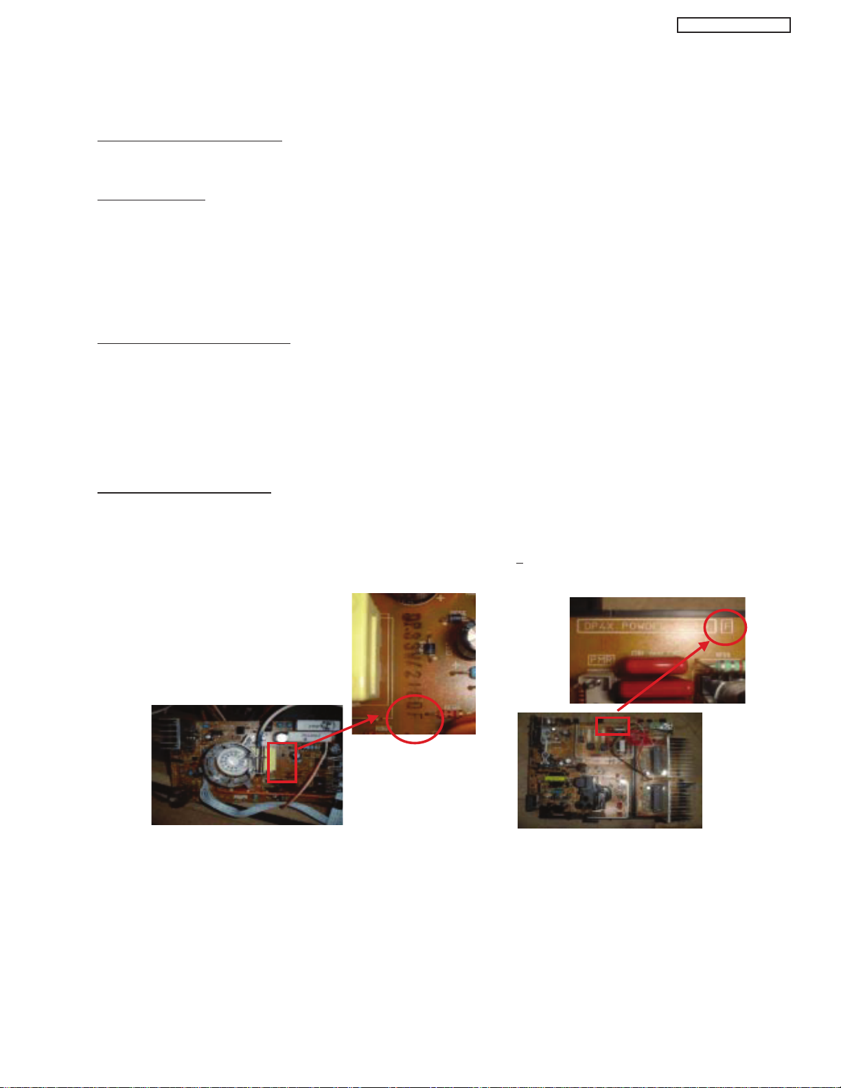
(4) Identification of lead-free PWB
2003 models >> not applied
2003 models >> mixed
2004 models >> lead-free solder is intoduced
On lead-free PWB, "F" is added at the end of stamp on PWB. (e.g. DP33W
F)
PT5-G/PW1-H
8

PT5-G/PW1-H
AGENCY REGULATORY
INFORMATION
Federal Communications Commission Notice
This equipment has been tested and found to comply with the limits for a Class B digital device, pursuant to Part 15 of
the FCC Rules. These limits are designed to provide reasonable protection against harmful interference in a residential
installation. This equipment generates, uses and can radiate radio frequency energy and if not installed and used in
accordance with the instructions, may cause harmful interference to radio communications. However, there is no
guarantee that interference will not occur in a particular installation. If this equipment does cause harmful interference
to radio or television reception, which can be determined by turning the equipment off and on, the user is encouraged
to try to correct the interference by one or more of the following measures:
• Reorient or relocate the receiving antenna.
• Increase the separation between the equipment and the receiver.
• Connect the equipment into an outlet on a circuit different from that to which the receiver is connected.
• Consult the dealer or an experienced radio/television technician for help.
Modifications
The FCC requires the user to be notified that any changes or modifications made to this device that are not expressly
approved by Hitachi Home Electronics (America), Inc. may void the user’s warranty.
Cables
Connections to this device must be made with shielded cables with metallic RFI/EMI connector hoods to maintain
compliance with FCC Rules and Regulations.
Any cables that are supplied with the system must be replaced with identical cables in order to assure compliance with
FCC rules. Order Hitachi spares as replacement cables.
Declaration of Conformity
This device complies with Part 15 of the FCC Rules. Operation is subject to the following two conditions: (1) this device
may not cause harmful interference and (2) this device must accept any interference received, including interference
that may cause undesired operation.
For questions regarding this declaration, contact:
Hitachi America, LTD.
Home Electronics Division
900 Hitachi Way
Chula Vista, CA 91914
Tel. 1-800-448-2244 (1-800-HITACHI)
ATTN: CUSTOMER RELATIONS
TABLE OF CONTENTS
9
ACKNOWLEDGMENTS
AND TRADEMARKS
This Plasma Television complies with VESA DDC2B specifications, Plug & Play
is a system with computer, peripherals (including monitors) and operating
system. It works when the monitor is connected to a DDC ready computer that
is running an operating system software that is capable for the plug & play.
When a Plug and Play PC is powered on, it sends a command to the Monitor
requesting identification. The Monitor sends back a string of data including its
characteristics.
TRADEMARK ACKNOWLEDGMENT
TM
DDC is a trademark of Video Electronics Standard Association.
IBM PC/AT and VGA are registered trademarkds of International Business Machines Corporation of the U.S.A.
Apple and Macintosh are registered trademarks of Apple Computer, Inc.
VESA is a trademark of a nonprofit organization, Video Electronics Standard Association.
PT5-G/PW1-H
This Class B digital apparatus meets all requirements of the Canadian Interference-Causing Equipment Regulations.
This Class B digital apparatus complies with Canadian ICES-003.
Cet appareil numérique de la classe B est conforme à la norme NMB-003 du Canada.
Cable Compatible Television Apparatus- Tèlèvision câblocompatible, Canada.
Notes on Closed Caption:
This Plasma Television receiver will display television closed captioning, ( or ), in accordance with
paragraph 15.119 of the FCC rules.
TruBass and the SRS ®symbol are trademarks of SRS Labs, Inc. TruBass technology is incorporated under license
from SRS Labs, Inc.
TABLE OF CONTENTS
10
PT5-G/PW1-H
6A
125V
F
6 A 125V
1 all AVC except 48W 0.9A (41W) 0.5W 14W AVC5-U
below
No.
Model Name
Indicated Value
Max Rating
Average
Rating (W)
Without POD.
less than 1W
Chassis
P
ST(W)
(W) (A)
With POD.
less than 14W
Part Model Name Chassis Name
Audio Video Control Center AVC75 AVC5-U
42” Plasma Display Monitor 42HDT51M PT5-G
55” Plasma Display Monitor 55HDT51M PW1-H
PULL
POWER
STANDBY (RED) ON (GREEN)
CH+CH-VOL+VOL- INPUT/EXIT
AUDIO VIDEO CONTROL CENTER
430mm
240mm
85mm
INTRODUCTION
The 42HDT51M and 55HDT51M are Plasma Television sets; They are constituted by the combination of two main parts, an AUDIO
VIDEO CONTROL Center, and the Plasma Display monitor.
Each part has a model name and a chassis name:
The AVC center is a box that controls most of the user functions of the complete TV set and conditions the signal before it arrives to the
monitors.
The 42” and 55” monitors contain the displaying device, which is the plasma display panel module, and the driving circuitry, which
receives the signal from the AVC center and after processing, delivers the image to the display module.
This HITACHI Service Manual is intended for the qualified service personnel and it contains the necessary information for
troubleshooting the Plasma television set in case of malfunction.
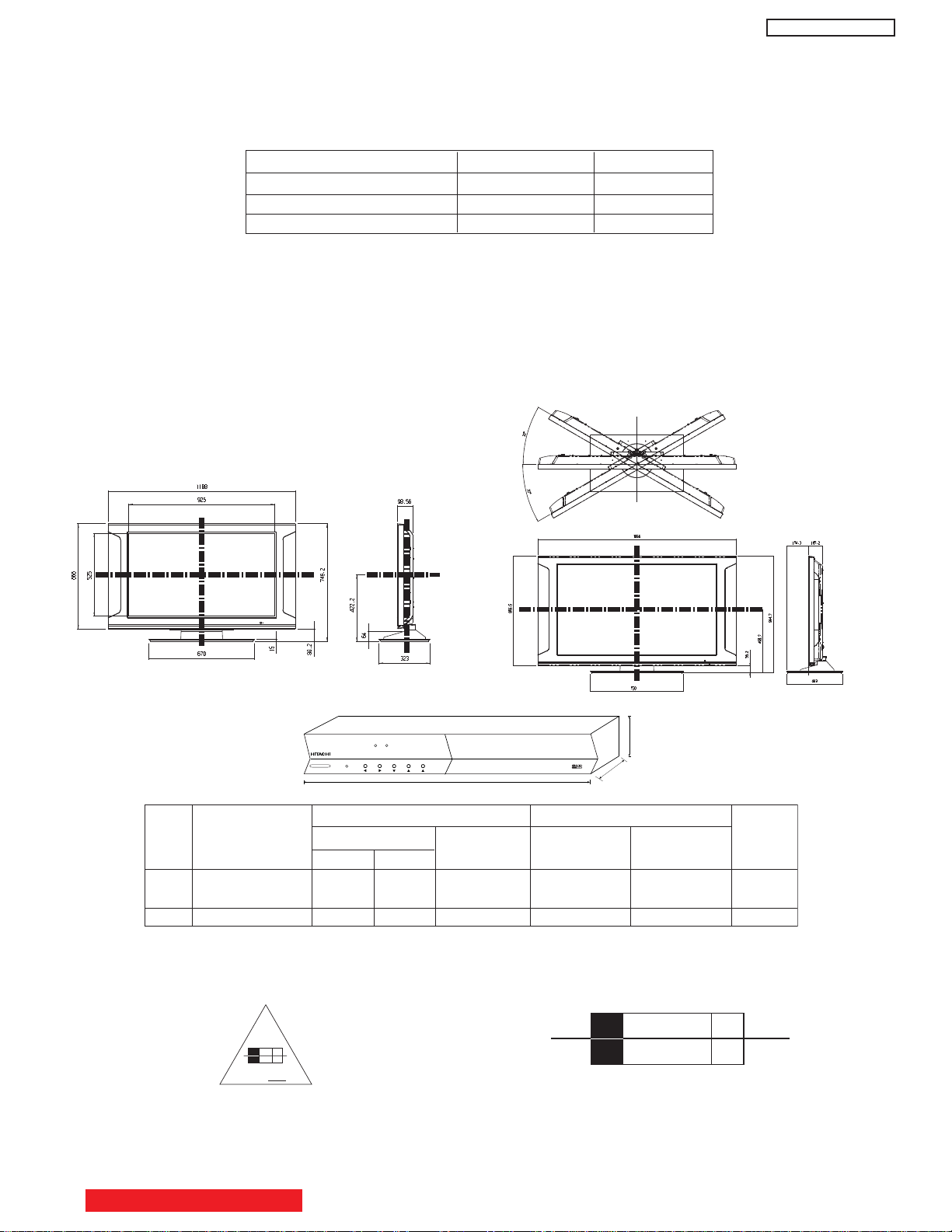
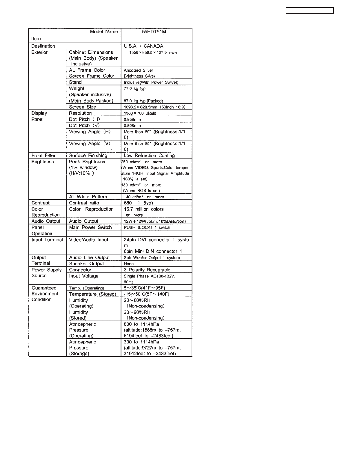
55HDT51M
DIMENSIONS:
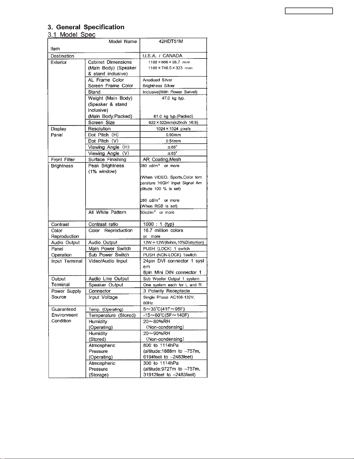
42HDT51M
POWER RATINGS:
CIRCUIT PROTECTION
CAUTION: Below is an EXAMPLE only. See Replacement Parts List for details. The following symbol near the fuse
Example:
“RISK OF FIRE - REPLACE FUSE AS MARKED”
TABLE OF CONTENTS
indicates fast operation fuse (to be replaced). Fuse ratings appear within the symbol.
The rating of fuse F901 is 6A - 125V.
Replace with the same type fuse for continued protection
against fire.
11
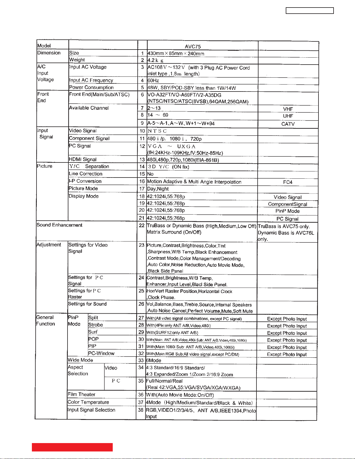
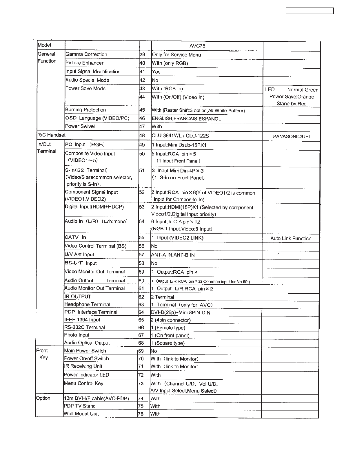
Specification Features
A- Plasma
PT5-G/PW1-H
TABLE OF CONTENTS
12
PT5-G/PW1-H
13
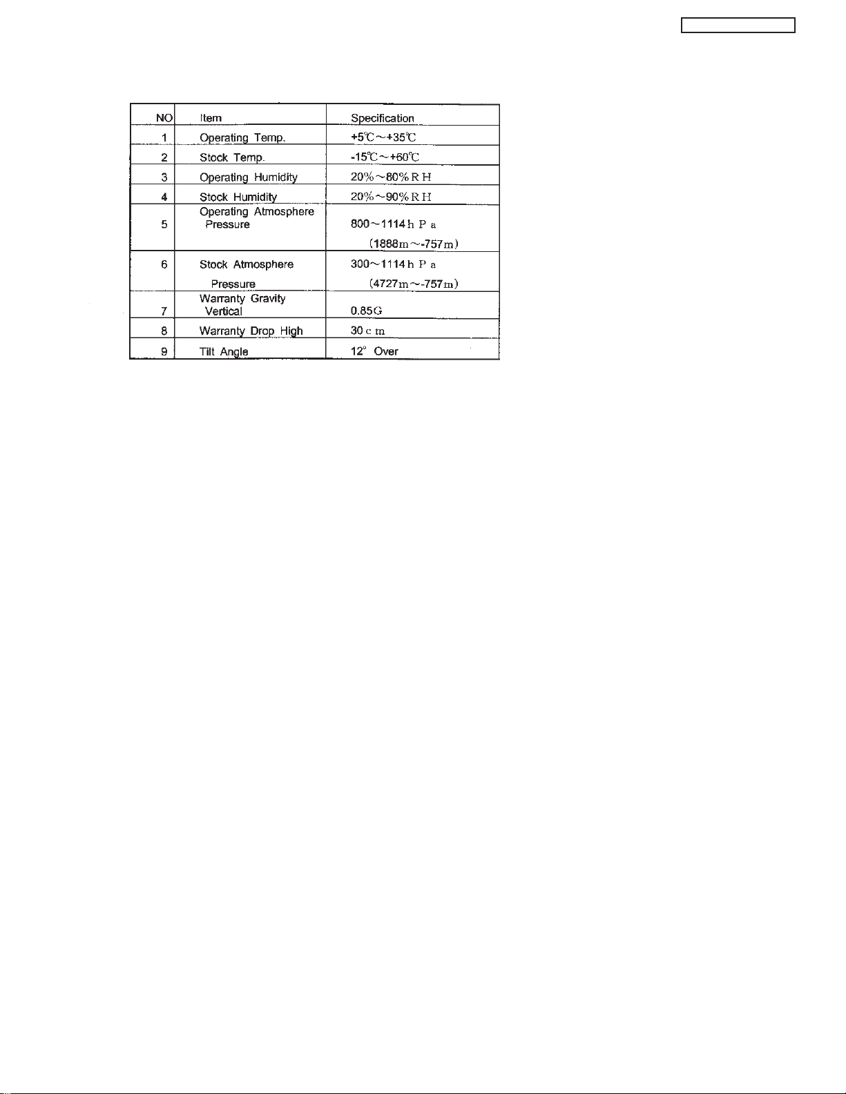
B- Environment
PT5-G/PW1-H
14
PT5-G/PW1-H
15
PT5-G/PW1-H
16
BASIC SETUP & OPERATION
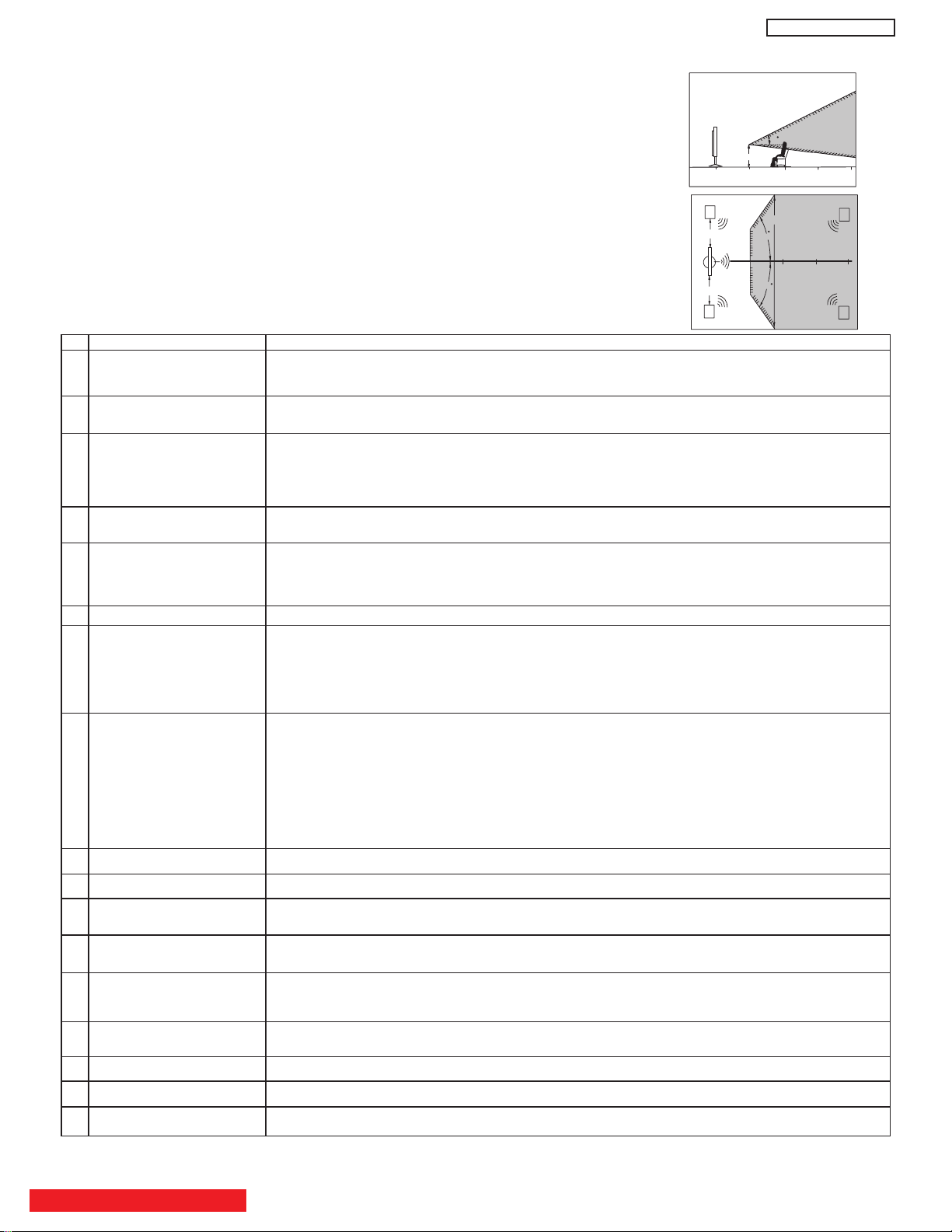
50
50
4" Minimum
4" Minimum
BEST
HORIZONTAL
VIEWING ANGLE
5’
10’
15’
20’
S
S
R
L
BEST
VERTICAL VIEWING
ANGLE
20
3’
0’
5’
10’
15’
20’
A buzzing sound might be heard when the plasma display monitor is turned on in a very quiet
room. This is due to the plasma panel drive circuit when it is functioning. This arching sound
is normal and it is not a malfunction.
Some infrared rays are emitted from the plasma display monitor’s panel that might affect other
infrared controlling equipment.
High-precision technology is used to manufacture the plasma display panel; But in some
cases, there are minor defects in some parts of the screen. Points that do not light, points
with brightness different from that of the periphery, points with color different from that of the
periphery, etc. Some pixels will always be on or always off. Please note that this is not a
malfunction.
When receving still picture signals, (e.g. channel number indication or clock indication) for a
while, you can see image-like when the picture varied. This is not a defect.
The plasma display panel is lighting the phosphors by the discharge of internal radiation. In
some cases, this may cause the temperature of the panel surface to increase. Please note
that this is not a malfunction. The Plasma TV surface temperature is higher than a
Cathode-ray-tube.
The plasma panel is made from glass. Heavy shock on the front panel might damage it.
When the PDP monitor is transported horizontally, the glass panel has the possibility of being
broken or increasing the picture defects. At the time of transportation, horizontal style is
prohibited. More-over, please treat the plasma panel with great care because of a precision
apparatus. Please instruct transporters so that it should be put into the packing box at the time
of shipment.(There is a possibility that breakage of the panel or defects will increase.)
Rough transportation might cause damage to the panel and pixel failure.
The plasma monitor illuminates phosphor to display images. The phosphor has a finite
illumination life. After extended periods of illumination, the brightness of the phosphor will be
degraded to such extent that stationary images would burn-in that part of the screen as
grayed-out images.
Tips to prevent such image retention are:
- Do not display images having sharp brightness differences or hi-contrast images, such as
monochrome characters and graphic patterns, for long.
- Do not leave stationary images appearing for long, but try to refresh them at appropriate
intervals of time, or try to move them using screen saver function.
- Turn down the contrast and brightness controls.
PDP television has luminosity and low contrast compared with CRT television.
When a screen is seen at point-blank range, a random fine grain may be visible to a dark part.
If an apparatus (VCR, etc.) antenna line is arranged near the monitor, the image may shake,
or disturbance may be received.
There is some time lag betweeen the picture and the sound. You can see lip motion that is
delayed compared to the sound.
Electric discharge/luminescence characteristic of the PDP panel also changes with peripheral
temperature. Moreover, since there is also high power consumption value, a specified
temperature environment is required.
Storing the plasma television for a period of more than 2 to 3 months without use might cause
an unstable picture when the set is turned on.
Operating altitude: 800 to 1114hPa (6194ft to -2484ft). Operating temperature: 41˚F to 95˚F.
Storage Altitude: 300 to 1114hPa (31,912 to -2484ft). Storage temperature: 5˚F to 140˚F.
Frequent use of the Power ON or OFF might trigger the power protection circuit. If the TV
does not turn ON, please wait a little before turning ON again.
1 Arching sound from
plasma display monitor’s
panel.
2 Interference for infrared
equipment.
3 Bright and dark spots
4 Picture Image (Spectrum)
5 Display panel surface
temperature is too high
6 Plasma Surface
7 Transportation
8 Image retention
9 Luminosity and contrast
10 Granular spots
11 Disturbance to video
apparatus
12 Lip Sync
13 About the use
environment of PDP
television (temperature)
14 Caution on prolonged
storage
15 Operating
16 Storage
17 Power ON or OFF
No. Items Notes
IMPORTANT NOTES
VIEWING
The major benefit of the HITACHI Plasma Television is its large viewing screen. To see this
large screen at its best, test various locations in the room to find the optimum spot for viewing.
The best picture is seen by sitting directly in front of the TV and about 8 to 18 feet from the
screen.
During daylight hours, reflections from outside light may appear on the screen. If so, drapes
or screens can be used to reduce the reflection or the TV can be located in a different section
of the room.
If the TV’s audio output will be connected to a Hi-Fi system’s external speakers, the best
audio performance will be obtained by placing the speakers equidistant from each side of the
receiver cabinet and as close as possible to the height of the picture screen center. For best
stereo separation, place the external speakers at least four feet from the side of the TV, place
the surround speakers to the side or behind the viewing area. Differences in room sizes and
acoustical environments will require some experimentation with speaker placement for best
performance.
TABLE OF CONTENTS
PT5-G/PW1-H
17
PT5-G/PW1-H
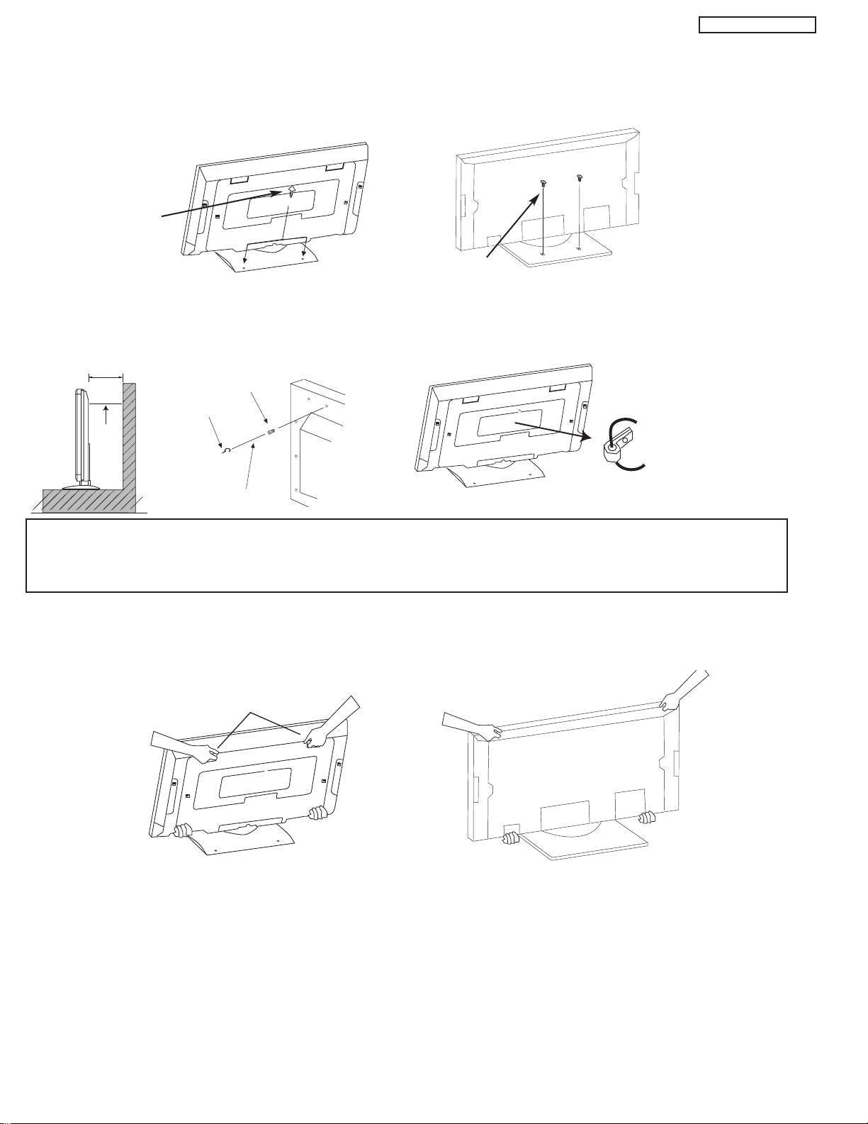
10cm (4 inches) or more
Wire
Stabilization bolts
(Provided)
String or Wire
Wood Screw
To take measures to prevent the Plasma Display from tipping over and prevent possible injury it is important to mount the unit
in a stable place.
Securing to a table-top
1. Using wood screws (two) fasten the set to the clamping screw holes on the rear of the Plasma Display stand as shown below.
2. Using commercially available wood screws, secure the set firmly in position.
Wood screw
two places
Wood screw
42”
two places
55”
Securing to a wall
1. Keep the Plasma Display monitor four inches away from the
wall except those hung to the wall mount bracket.
2. Secure the monitor to the wall as shown below.
42”
NOTES: 1.
Do not block the ventilation holes of the Plasma Display monitor or the AVC center. Blocking the ventilation holes might cause fire
or defect.
2. The plasma television has two AC cords, one on the AVC center and the other on the Plasma Display monitor. In case of an
abnormal symptom, unplug both AC cords.
3. If you purchased the wall mount bracket option, please ask for professional installer. Do not install by yourself.
Caution when moving the main unit
As this product is heavy, whenever it is moved, two people are required to transport it safely. Whenever the unit is moved it should be
lifted forward using the two handgrips at the back for the 42”, and at the top and base on both sides of the 55” for stability. When moving
the Display Monitor, lift the handles and the bottom frame as shown below. Do not grab the speakers or the back cover when lifting.
Handgrips
42”
55”
ANTENNA
Unless your Plasma Television is connected to a cable TV system or to a centralized antenna system, a good outdoor color TV antenna
is recommended for best performance. However, if you are located in an exceptionally good signal area that is free from interference
and multiple image ghosts, an indoor antenna may be sufficient.
LOCATION
Select an area where sunlight or bright indoor illumination will not fall directly on the picture screen. Also, be sure that the location
selected allows a free flow of air to and from the perforated back cover of the set.
To avoid cabinet warping, cabinet color changes, and increased chance of set failure, do not place the TV where temperatures can
become excessively hot, for example, in direct sunlight or near a heating appliance, etc.
18
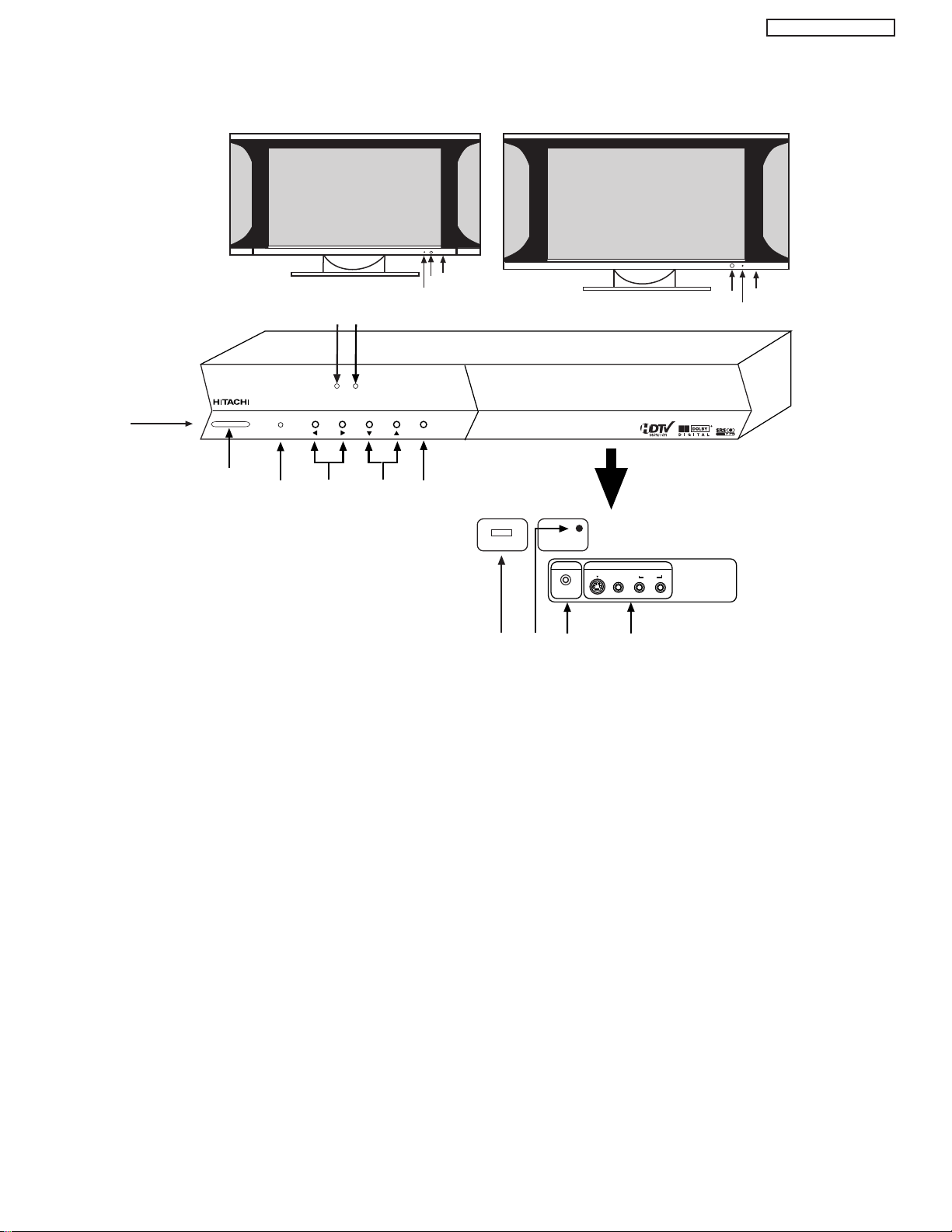
FRONT PANEL CONTROLS
(AVC)
AUDIO VIDEO
CONTROL
CENTER
42”
DISPLAY
MONITOR
f
g
h
STANDBY (RED) ON (GREEN)
MAIN POWER
55”
DISPLAY
MONITOR
g
h
STANDBY (RED) ON (GREEN)
PULL
POWER
MENU/SELECT
L/(MONO) R
VIDEO
S-VIDEO
INPUT 5
PHONES
AUDIO
i
j
d
a
g
f
e
c
h
STANDBY (RED) ON (GREEN)
CH+CH-VOL+VOL- INPUT/EXIT
AUDIO VIDEO CONTROL CENTER
k
f
PHOTO INPUT
b
PT5-G/PW1-H
FRONT VIEW
a MENU/SELECT button
This button allows you to enter the MENU, making it possible to set TV features to your preference without using the remote. This
button also serves as the SELECT button when in MENU mode.
b PHOTO INPUT
Insert USB cable from your Digital Camera to view your digital still pictures.
c INPUT/EXIT button
Press this button to select the desired input, VIDEO 1 to 5, RGB, IEEE 1394, Photo Input or Ant A/B source. Your selection is shown
in the top right corner of the screen. This button also serves as the EXIT button when in MENU mode.
d CHANNEL selector
Press these buttons until the desired channel appears in the top right corner of the TV screen. These buttons also serve as
the cursor down (
e VOLUME level
Press these buttons to adjust the sound level. The volume level will be displayed on the TV screen. These buttons also serve as
the cursor left (
H) and up (G) buttons when in MENU mode.
F) and right (E) buttons when in MENU mode.
19
PT5-G/PW1-H
Indicating Lamp Power Status Operating
Off Off When the main power switch is set
OFF.
Lights Red Off When the main power switch on the display
(Stand-by) monitor is ON, and the AVC Center is OFF.
Lights Green On Display monitor MAIN POWER is ON and
AVC Center power is ON.
Lights Orange Off Display monitor MAIN POWER is ON and
(Flashing) (Power Saving) and AVC Center power is ON, with no signal
input except antenna (no sync. signal).
MAIN POWER
MAIN POWER
MAIN POWER
STANDBY(RED) ON(GREEN)
f POWER button
Display Monitor “MAIN POWER” button
This power button is for the complete system, and must be turned ON/OFF manually. It is recommended to leave the “MAIN
POWER” to ON condition (lights red) for stand-by mode.
or
42”
AVC POWER button
The AVC power can be turned ON/OFF manually or by remote control. Turning on the AVC Power will only turn on the AVC box if
the “MAIN POWER” of the display monitor is off.
55”
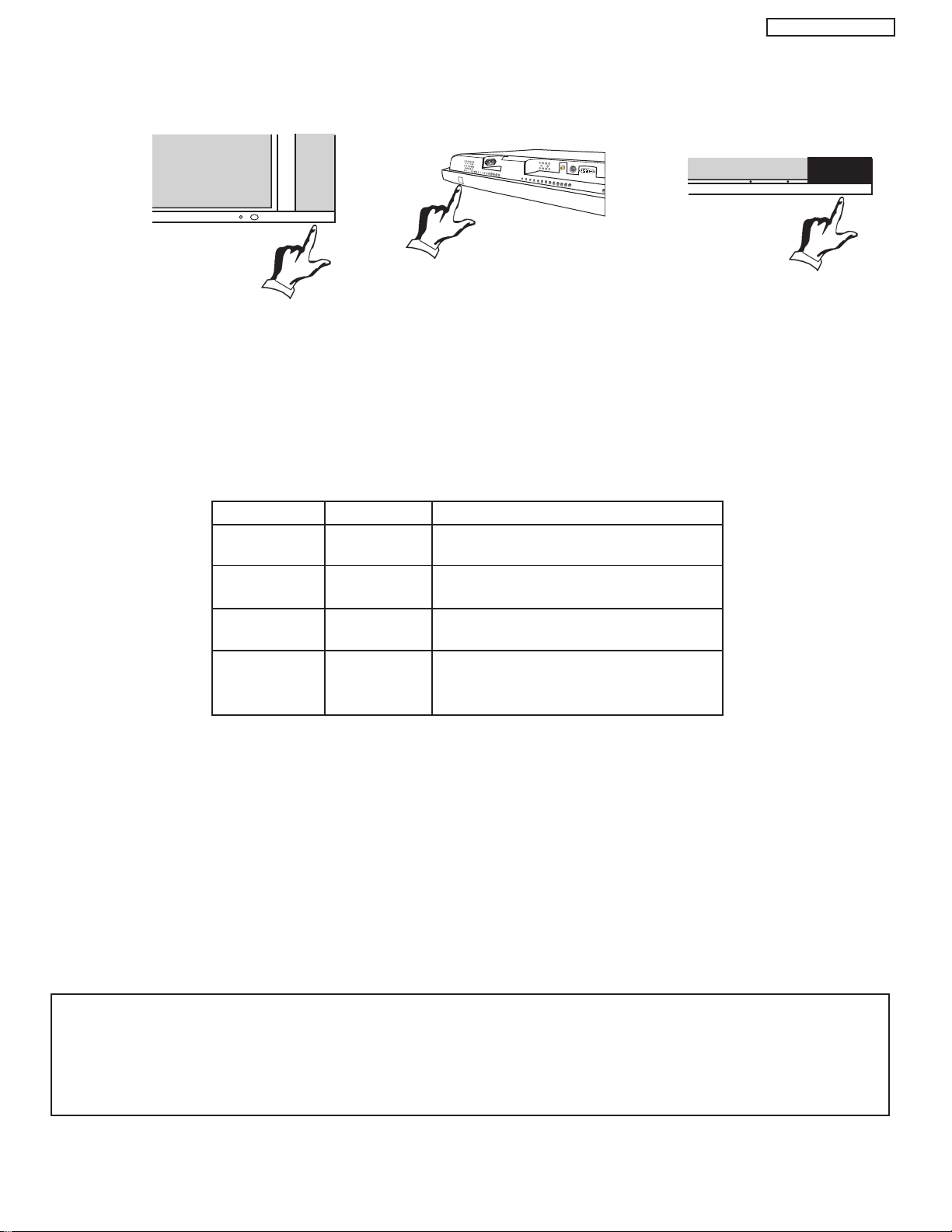
g POWER light indicator
To turn the monitor ON, press the main power switch located on the lower right side of the monitor. A red stand-by indicator lamp
located on the lower right corner of the front bezel will illuminate. The PDP is now ready for remote on/off operation.
h REMOTE CONTROL sensor
Point your remote at this area when selecting channels, adjusting volume, etc.
i FRONT INPUT JACKS (for VIDEO: 5)
Use these audio/video jacks for a quick hook-up from a camcorder or VCR to instantly view your favorite show or new recording.
Press the INPUTS button then use the CURSOR PAD and the SELECT button on the remote control to select INPUT 5. VIDEO: 5
appears in the top right corner of the TV screen. If you have mono sound, insert the audio cable into the left audio jack.
j PHONES JACK
Use this jack for your head-phones. The TV’s internal speakers can also be heard. Turn off the internal speakers if you wish to
listen to the head-phones only.
k LEARNING AV NET Sensor
Point your equipment’s remote control at this area while using the AV NET Learning Wizard.
NOTES: 1. Your HITACHI Plasma TV will appear to be turned OFF (lights orange) if there is no video input when VIDEO: 1, 2,
3, 4, 5, or RGB is selected. Check the Power Light to make sure the Display Monitor is turned off or in Stand-by
mode (lights red) when not in use.
2. Remote Control can not turn ON/OFF the “MAIN POWER” of the display monitor.
20
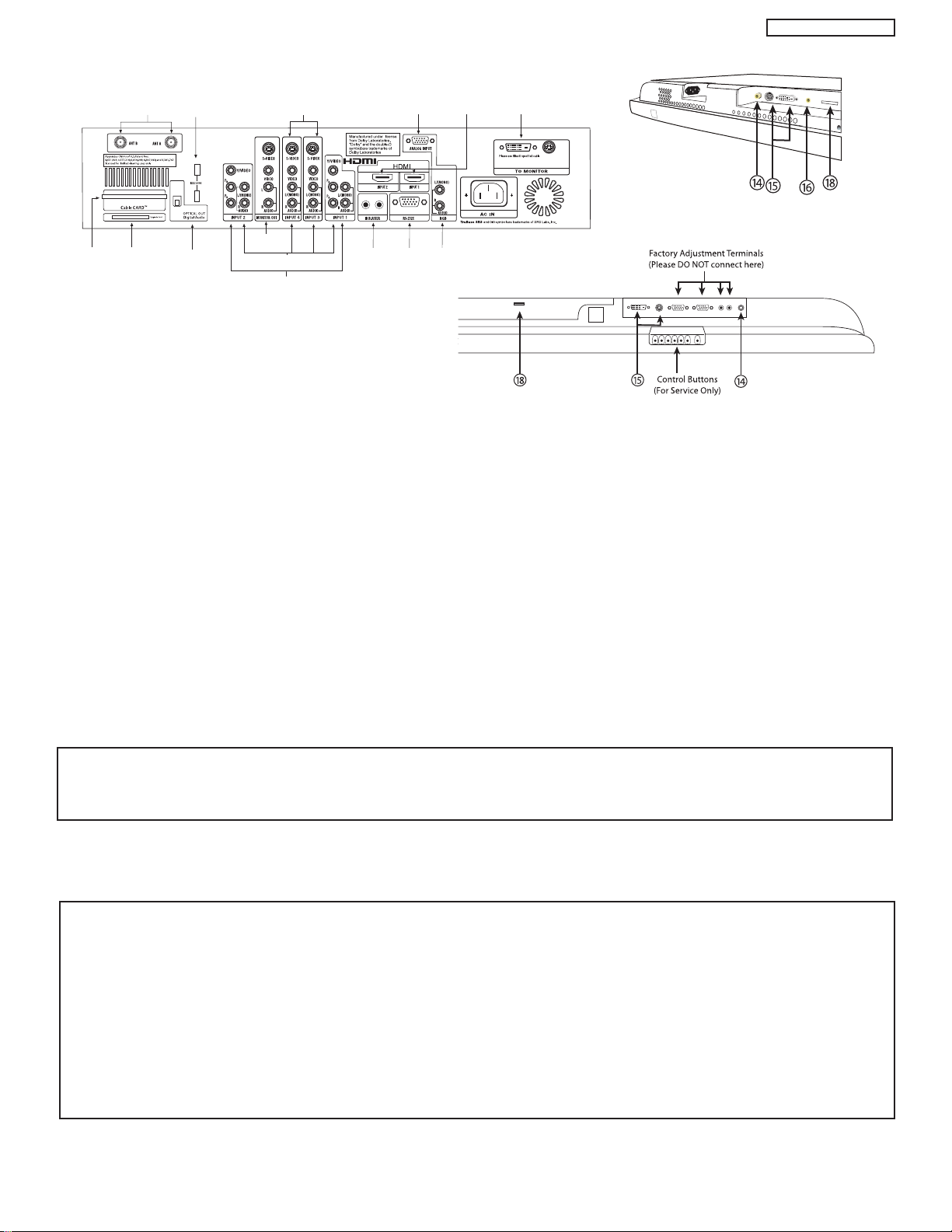
REAR PANEL JACKS
b
c
f
q
d
h
e
g
m
a
lk
ji
s
42” Monitor Bottom View
Audio Video Control Center (AVC)
55” Monitor Bottom View
PT5-G/PW1-H
a Antenna Input
The remote control allows you to switch between two separate 75-Ohm RF antenna inputs, ANT A and ANT B. ANT A input can
be displayed as a main picture or sub-picture. ANT B can only be displayed as a main picture (ANT B cannot be displayed as a
sub-picture).
b Audio/Video Inputs 1, 2, 3 and 4
By using the INPUTS button, the CURSOR PAD, and the SELECT button of the remote control, you can select each video source.
Use the audio and video inputs to connect external devices, such as VCRs, camcorders, laserdisc players, DVD players etc. (if you
have mono sound, insert the audio cable into the left audio jack).
c MONITOR OUT
These jacks provide fixed audio and video signals (ANT A/B, INPUT 1~5) which are used for recording. Use the S-VIDEO Output
for high quality video output. Component signal to Input 1 and 2, RGB and HDMI inputs will not have monitor output.
d Optical Out (Digital Audio)
This jack provides Digital Audio Output for your audio device that is Dolby®Digital and PCM compatible, such as an audio amplifier.
e S-VIDEO Inputs 3 and 4
Inputs 3 and 4 provide S-VIDEO (Super Video) jacks for connecting equipment with S-VIDEO output capability.
NOTES: 1. You may use VIDEO or S-VIDEO inputs to connect to INPUT 3 and 4, but only one of these inputs may be used at a
f Component: Y-P
Inputs 1 and 2 provide Y-PBPRjacks for connecting equipment with this capability, such as a DVD player or Set Top Box. You may
use composite video signal for INPUTS 1 and 2.
NOTES: 1. DO NOT connect composite VIDEO and S-VIDEO to Input 3, 4 or 5 at the same time. S-Video has a higher priority
time.
2. S-VIDEO output may be used for recording, only when the input is of S-VIDEO type.
Inputs
BPR
over video input.
2. Your component outputs may be labeled Y, B-Y, and R-Y. In this case, connect the components B-Y output to the AVC
Box’s PBinput and the components R-Y output to the AVC Box’s PRinput.
3. Your component outputs may be labeled Y-CBCR. In this case, connect the component CBoutput to the AVC Box’s
PBinput and the component CRoutput to the AVC Box’s PRinput.
4. It may be necessary to adjust TINT to obtain optimum picture quality when using the Y-PBPR inputs.
5. To ensure no copyright infringement, the MONITOR OUT output will be abnormal, when using the Y-PBPRjacks, RGB
and HDMI inputs.
21
PT5-G/PW1-H
g RGB - Analog Input
Use this 15-pin D-Sub input for your external devices with RGB output.
h RGB - Audio Input
Connect audio for RGB input (if you have mono sound, insert the audio cable into the left audio jack).
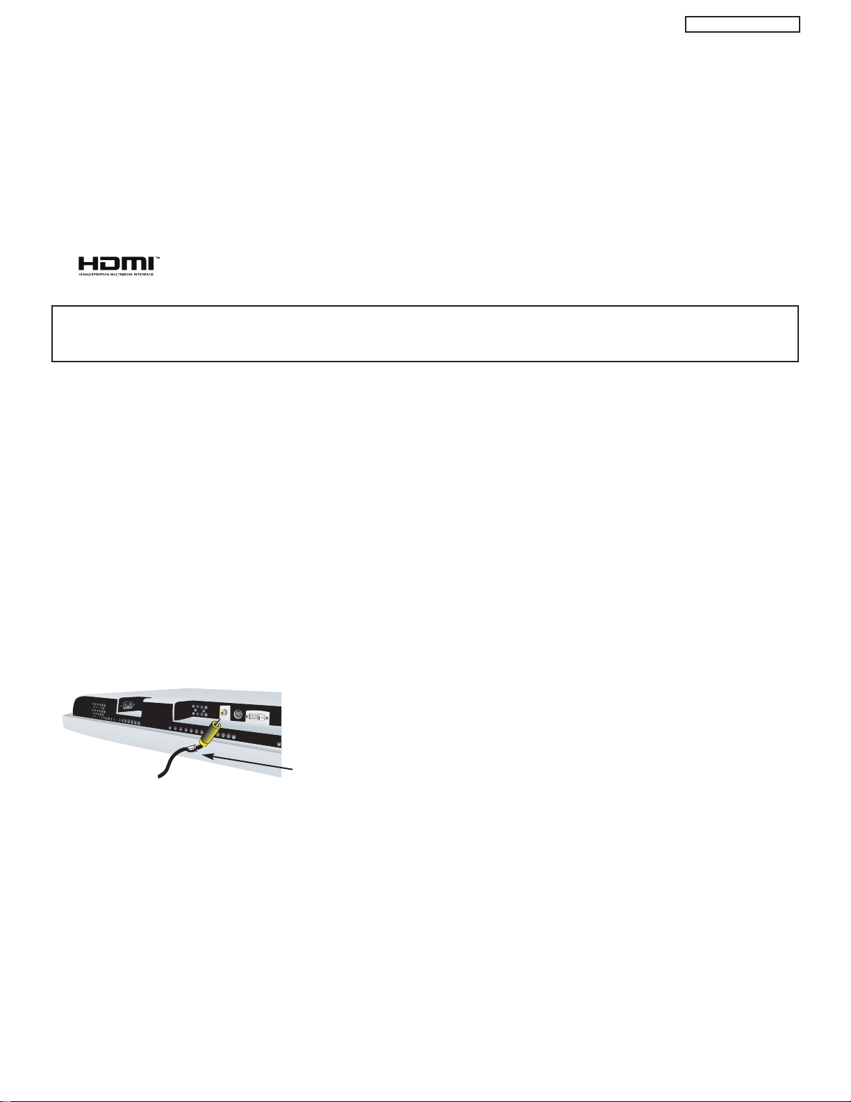
i HDMI - Digital Input (INPUT 1 and INPUT 2)
About HDMI
HDMI is the next-generation all digital interface for consumer electronics. HDMI enables the secure distribution of uncompressed
high-definition video and multi-channel audio in a single cable. Because digital television (DTV) signals remain in digital format,
HDMI assures that pristine high-definition images retain the highest video quality from the source all the way to your television
screen.
Use the HDMI input for your external devices such as Set-Top-Boxes or DVD players equipped with an HDMI output connection.
HDMI, the HDMI logo and High-Definition Multimedia Interface are trademarks or registered trademarks of HDMI Licensing LLC.
NOTES: 1. The HDMI input is not intended for use with personal computers.
2. Only DTV formats such as 1080i, 720p, 480i and 480p are available for HDMI input.
j To Monitor
Connect the Monitor Connection Cable to the AVC center’s “TO MONITOR” connector, and to the display monitor’s “FROM AVC”
connector.
k IR Blaster
This jack provides IR output to your external components (VCR, Cable box, DVD player, etc.). With this connection, your external
components can automatically be controlled by the A/V network feature. This connection will allow you to control the external
components with your Plasma Television’s remote control in TV mode.
l RS232C Input
For use with third party home Audio/Video control systems which are commercially available. Please see your dealer regarding
these “non Hitachi” home control systems.
m IEEE1394
These jacks provide a digital interface for your external digital devices, such as a Digital VCR (D-VHS or Set-Top-Box) by means
of a single cable. When using IEEE1394 connections, you enable video and audio digital data exchange between a compatible
device. This connection also enables you to control basic equipment functions (such as VCR play, rewind, fast forward, stop, etc.)
from your TV On-Screen Display.
n Subwoofer Out
Connect this SUB WOOFER OUT output to the external audio component input using the sub woofer cable provided.
Ferrite Core
Sub-woofer cable (RCA Type)
o To AVC
Connect the Monitor Connection cable from the AVC center’s “TO MONITOR” to these connectors (“FROM AVC”).
This is a Hitachi proprietary cable, do not use any other cable.
p SUB-POWER button
This power is for serviceman usage.
q Upgrade Card
This card slot is for future software upgrades. Hitachi will notify you if a software upgrade is required for your TV. In order to receive
written notification, please complete and return your warranty card.
r To Power Swivel Connector
Connects to the Power Swivel Table Top Stand.
For model 55HDT51, the stand (TTS55) is optional.
22
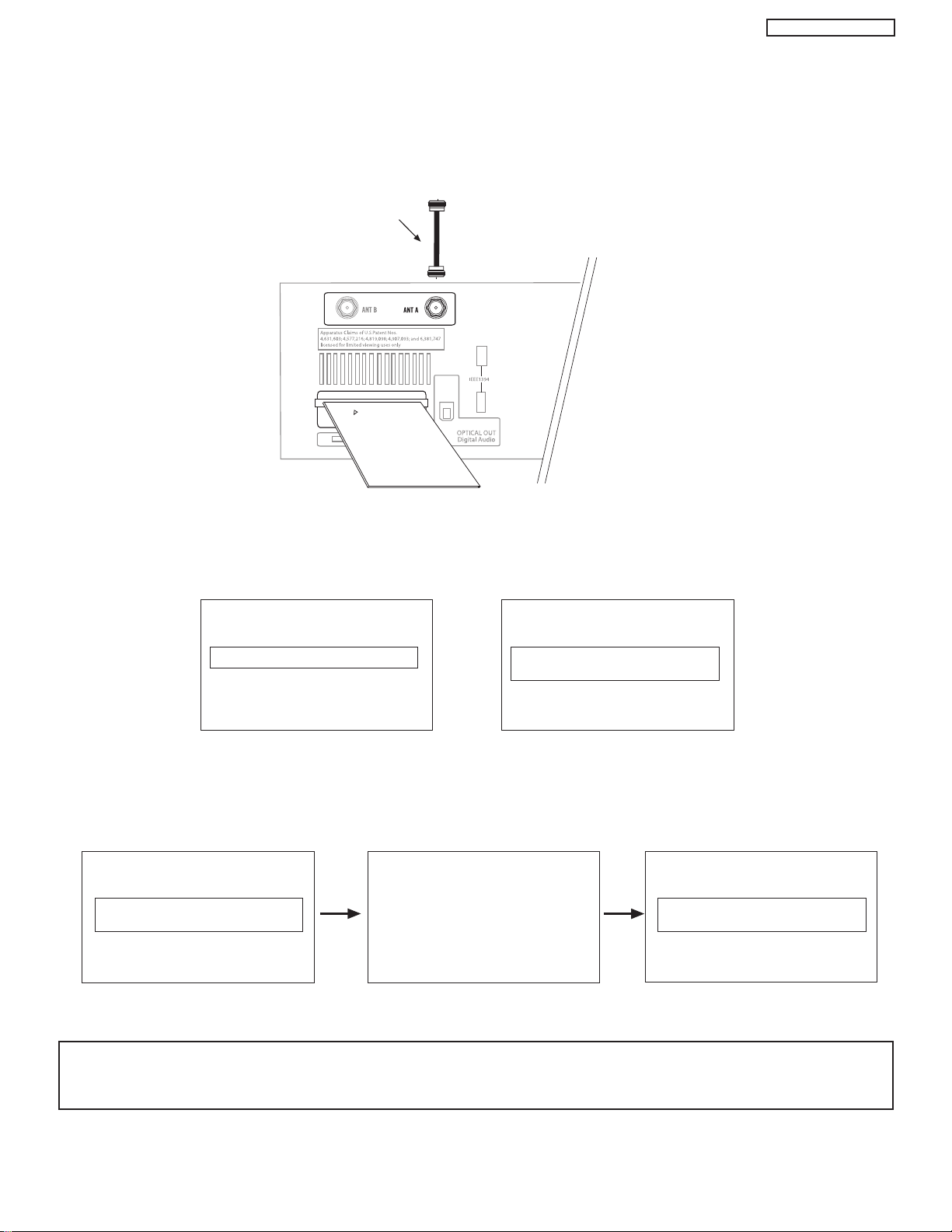
CONNECTING AV NETWORK
INSERT THIS END
CableCARD
Digital Cable
CableCARD is installed CableCARD
is not installed
OR
In order to start cable service
for this device, please contact
your cable provider
CableCARD(tm): 123-456-789-1
Host: 123-456-789-1
Data: 123-456-789-1
UnitAddress: 123-456-789-1
Acquiring Data.
Please wait.
Press EXIT to return
Not an Authorized Channel
PT5-G/PW1-H
s CableCARD Slot
This slot is for the CableCARD that will be provided by your local cable operator to gain access to chosen cable channels. The
CableCARD will allow you to tune digital and high definition cable channels. Please call your local cable operator if this service is
available before requesting a CableCARD (also known as Point of Deployment (POD) module).
Connect a coaxial cable to ANT A terminal of the Rear Panel Jacks.
Insert the CableCARD into the slot (Top of card should be facing up as shown).
Rear Panel of AVC
If the CableCARD is properly installed or not installed, the TV will display the following respective screens.
After the CableCARD is installed, wait until the second screen below appears. The third screen below will appear if a channel is not
authorized for viewing. Press the EXIT button to exit the second screen.
Please take note of all information on the screen (you will provide this information to your cable operator). Call your cable operator
and give them the information from the card to start your cable service.
NOTES: 1. A digital cable subscription is required.
2. Antenna B will not be available when CableCARD is inserted.
3. Do not insert a PCMCIA card into the CableCARD slot.
23

PT5-G/PW1-H
ADJUSTMENTS TABLE OF CONTENTS
TO GO TO A SECTION, CLICK ON ITS HEADING BELOW
1 Adjustment procedure start up....................................................................................................25
1.1 How to get into adjustment mode ................................................................................25
1.2 Changing data and selecting adjustment code............................................................25
2 Memory initialize ........................................................................................................................25
2.1 Memory initialize operation ..........................................................................................25
2.2 Factory and service adjustments ................................................................................26
3 Amplitude Adjustment ................................................................................................................26
3.1 RGB Amplitude Adjustment ........................................................................................26
3.2 Sub-Contrast Adjustment ............................................................................................26
3.3 Brightness Check ........................................................................................................26
4 Vs, Va Voltage Adjustment..........................................................................................................27
5 White balance adjustment ..........................................................................................................28
5.1 Video Color Temperature Adjustment (High) ..........................................................................28
5.2 Video Color Temperature Adjustment (Medium)..........................................................28
5.3 Video Color Temperature Adjustment (Standard) ........................................................29
5.4 Video Color Temperature Adjustment (Black and White) ............................................29
5.5 PC Color Temperature Adjustment (High) ..................................................................29
5.6 Color Temperature Setting Correction ........................................................................29
5.7 White Balance Adjustment OSD Flowchart Diagram ..................................................30
6 Screen Check ............................................................................................................................31
7 Settings For Delivery ..................................................................................................................32
8 I2C Adjustment Data ..................................................................................................................37
TABLE OF CONTENTS
24
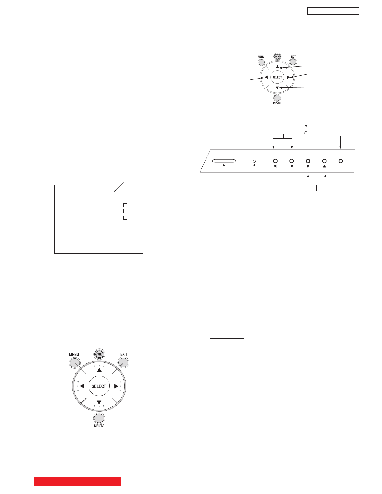
1 ADJUSTMENT PROCEDURE START-UP
ADJUST MODE XXXX
RGB(480P)
Sub Cont. Adj.
FACT RESET
FIRMWARE
VERSION
Power
Button
Indicator
LED
Infrared
Sensor
INPUT/
EXIT
Volume/LeftRight Cursor
Channel/UpDown Cursor
POWER
STANDBY (RED) ON (GREEN)
CH+CH-VOL+VOL- INPUT/EXIT
Remote Control Buttons
Front Panel of AVC
Change
Selection (Up)
Increase
Data Value
Change
Selection (Down)
Increase
Data Value
The 42HDT51M and 55HDT51M PDP TV sets undergo
thorough adjustment procedures during their assembly
process. These adjustments must be done to assure the
best performance of the PDP set for the consumer.
Also, after servicing, these same adjustments must be
done. The adjustments are all made through the I
by changing data in the Adjustment mode menu.
Table 2 on pages 38-46 shows the complete parameter
list with a brief description, signal format, the adjustment
range and the initial data.
1.1 HOW TO GET TO ADJUSTMENT MODE
Chassis adjustment can be done by using the AVC75
front control panel buttons with PDP set turned off.
Press “POWER” and “INPUT” keys at the same time,
and hold for more than 3 seconds. Release the
“POWER” button first and then immediately the
“INPUT” button. The PDP set turns on in adjustment
mode with OSD as follows.
2
C bus
PT5-G/PW1-H
To escape from Adjustment Mode press “INPUT” key to exit
service adjustment mode.
Table 2 can be found on pages 38-46.
1.2 CHANGING DATA AND SELECTING ADJUSTMENT
CODE
When the PDP set is in adjustment mode, the cursor F, E,
G, H and MENU keys of the remote control or front panel
may be used as the adjustment keys.
A. Use any Hitachi remote control when making an
adjustment.
G, H keys are used for selecting adjustment code.
F, E keys are used for changing data values.
MENU key is used to advance through the adjustment
mode menus and pages.
B. To make a selection, use the CURSOR keys on the AVC
front control panel or the Remote Control.
C. After finishing the necessary adjustment press the R/C
EXIT key or EXIT key on the front panel.
Adjustment mode is released and PDP set returns to
normal condition.
2 MEMORY INITIALIZE
2.1 MEMORY INITIALIZE OPERATION
NOTE: The execution of this function returns the
adjustment codes to the preset values, therefore,
adjustment data will be lost.
There are two procedures for memory initialize, this is
the first.
Procedure 1
(1) Enter Adjustment mode by the method described in
sub-items 1.1 and 1.2 from item 1 (“Adjustment
procedure start up”).
(2) Get to the second page of Adjust Mode by pressing
remote control “Menu” key once, or with either the
R/C or front panel
G, H cursor keys several times.
(3) Select MEMORY INIT adjust code.
(4) Activate MEMORY INIT by pressing
E cursor key for
more than 3 seconds.
(5) Check that the receiving channel goes to CH03. Unit
is set to preset values.
BACK TO ADJUSTMENTS
25
PT5-G/PW1-H
V
1
V
3
V
2
AVC75
Can be seen at black A3*
Can be seen slightly from black A5*
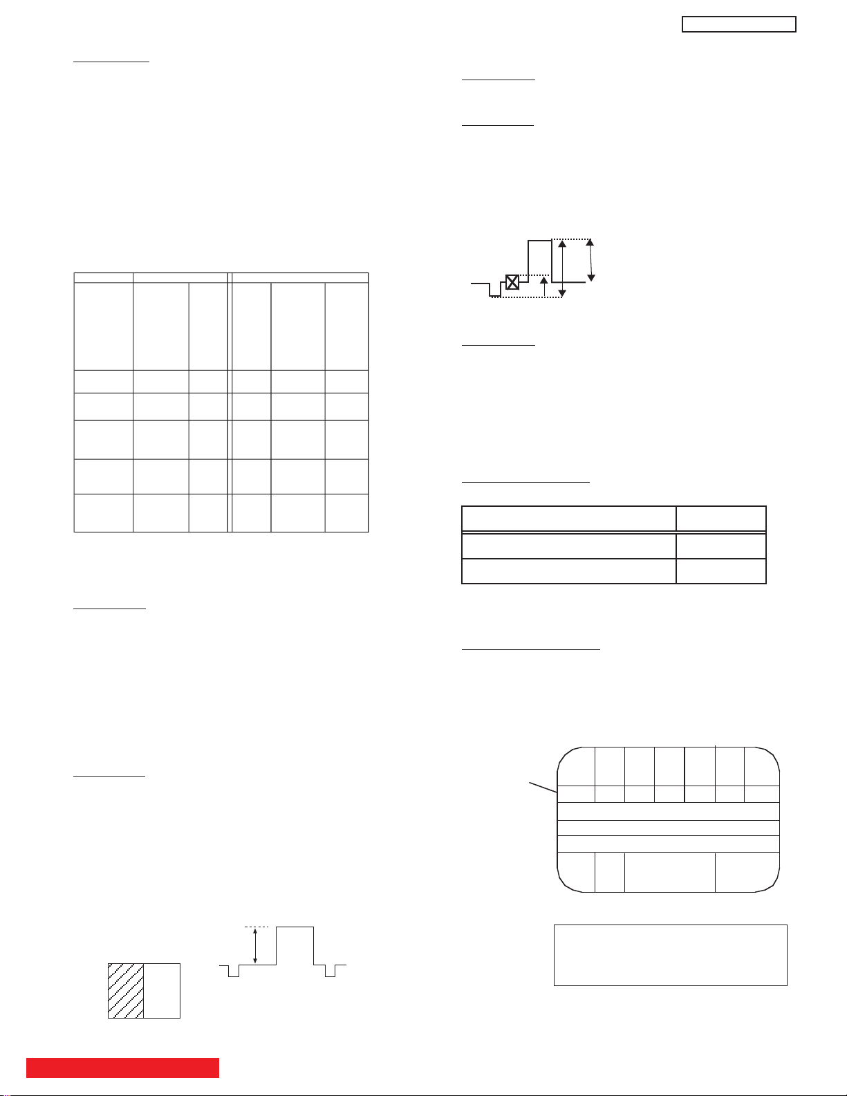
SIGNAL Adjustment Item Initial Value Set Value
480p BRIGHT CENT. 50H 53H
720p BRIGHT CENT. 50H 53H
VGA(60) BRIGHT CENT. 50H 4EH
RGB amplitude adj. signal
Black
White
0.7V
Recommended Equipment:
ASTRO VG-823 Digital Video Generator
with RB-649 Remote Box.
-Remarks
TABLE 1
A
7A6A5A4A3A2A1
White 100%
7 step gray scale
A
4 has tolerance.
A
4 can be between black and
Slightly from black.
Color Bar Signal
Adj. Items Memory Init.
W/B
Init.(No
need to
use)
change
of FCunit
change of
PDP-module
or change of
I002(EEPROM
) on
SIG/AUDIO
PWB
change of
I003(EEPR
OM) on
AV PWB
or Memory
Init.
Video white
blance Adj.
affect Adj.
PC white
blance Adj.
affect Adj.
Video RGB
Amplitude
Adj.
Adj.
PC RGB
Amplitude
Adj.
Adj.
Sub-contrast
Adj.
affect
(M-CONT4;
S-CONT4)
Adj.
Initialization
Adjustment
Procedure 2
(1) Short PRST connector on the AVC AV PWB and
check that the set return to delivery settings (CH 03).
(2) Do not unplug from AC outlet until this operation is
completed and do not perform any key operation
either. After this operation, each factory setting and
adjust mode data should reset to delivery setting
automatically.
2.2 FACTORY AND SERVICE ADJUSTMENTS
The adjustment item that is affected by the memory
initialize operation is shown below:
3.2 SUB-CONTRAST ADJUSTMENT
Preparation
Receive Sub-contrast adjustment signal (Fig. 1).
Adjustment
(1) Select ‘SUB CONTRAST’ of Service Adj. Menu.
E for over 2 seconds and have it perform
Press
automatic adjustment. When it’s completed, ‘Auto
Adjusting’ on the screen will be disappeared.
Fig. 1
Full White
(RF Input ANT A))
=1.0 Vp-p (when
V
1
=100IRE with
V
2
=7.51IRE)
V
3
3.3 BRIGHTNESS CHECK
Preparation
(1) Start checking 20 minutes or more after the power is
turned ON.
(2) Receive the color bar signal.
(3) The vertical incident illumination on the screen
should be 20 lux or less.
(4) Picture Format is 16:9 standard mode.
(5) Select Day mode and reset.
3 AMPLITUDE ADJUSTMENT
(AVC CENTER)
3.1 RGB AMPLITUDE ADJUSTMENT
Preparation
(1) Select “Video” - “Picture Mode” - “Day” - “Reset”. Set
“Reset” of “Video” menu when PC input is selected.
(2) Input 525p(480p) of RGB amplitude adj. signal into
INPUT1(Component) input.
(3) Input VGA(60Hz) RGB amplitude adj. signal into
RGB input.
Note: Perform pre heat-run for more than 20 min. before
adjusting.
Adjustment
(1) Receive 525p(480p) signal (Aspect 16:9 Standard).
(2) Select ‘RGB(480p)’ of Service Adj. menu. Press
right cursor key (
E) over 2 seconds and have it
perform automatic adjustment. When it’s completed,
‘Auto Adjusting’ on the screen will disappear.
(3) Receive PC signal (VGA(60Hz)), (Aspect Full).
(4) Similarly as (2), select ‘RGB(PC)’ of Service Adj.
BACK TO ADJUSTMENTS
Menu, by pressing SEL button. Press
do automatic adjustment.
E for 2 sec. to
26
Checking Procedure
(1) Check the brightness as below.
Note: If set black level is NG, readjust item 3.1 RGB
amp. adj. and 3.2 Sub Contrast adj.
Measuring Conditions
(1) At the signal electric field strength 75± dBµ, the
10
specification mentioned above should be satisfied.
(2) At the input electric field 46-106dB
µ, there should be
no abnormality.
* From color bar pattern below.
0
2003ï 3ï 5
TITLE
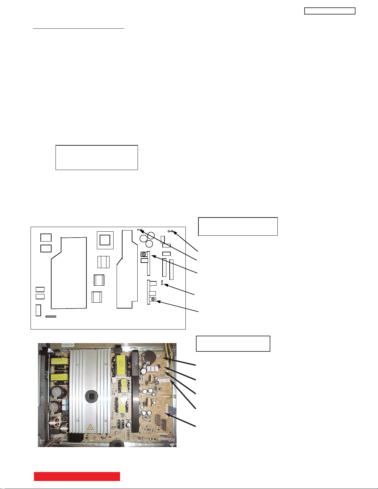
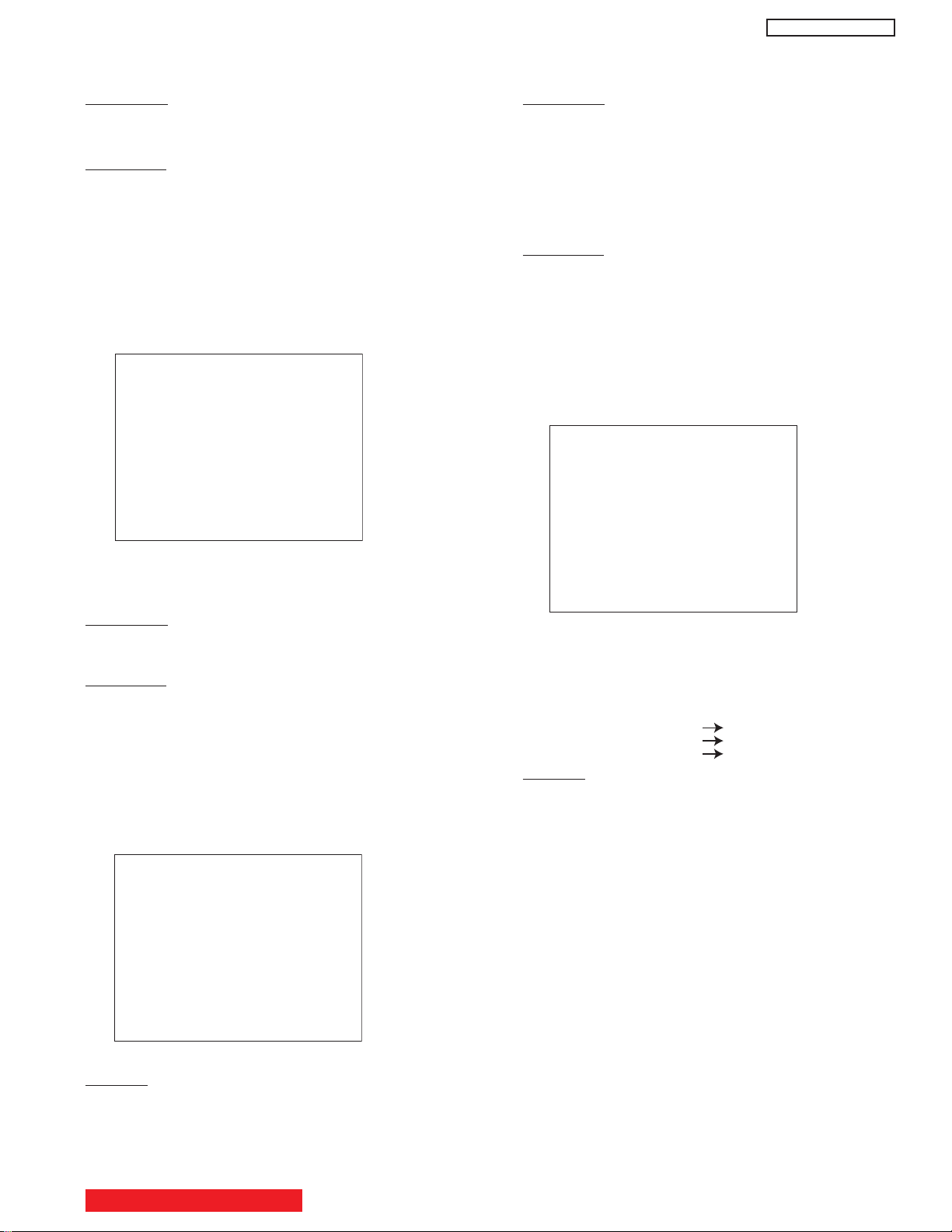
4. Vs, Va voltage adjustment
Adjustment part:
-Preparation
1.Turn on the set and perform pre-heat run more than 1 minute with a snow noize screen.
2.Receive full black pattern (blanking level) signal (or Video No signal; in this case,
it will be autmatically turned off after a few seconds because of power save function).
3.Connect voltmeter leads to the Vs or Va and GND test points on power unit.
(Measurement error of voltmeter should be Less than 0.02V)
-Adjustment
(1)Turn VsADJ to adjust Vs voltage to be within 0.1V of the value specified
in the label on the panel. *
1
(2)Turn VaADJ to adjust Vs voltage to be within 0.2V of the value specified
in the label on the panel. *
1
(3)Reconfirm that Vs voltage remains within 0.1V of the value.Readjust if Itís outside the margin.
Label example*
2
-Remarks
*1. Permissive level of voltage in case sufficient time of heat-run performed.
Vs: within 0.45V, Va: within 0.55V
<LOT>N6
Vs=80.0V Va=60.0V
V• =140.0V Vx=60.0V
Power unit for 42 inch
PIN502• GND
PIN501• VS
VsADJ(on IC591 PWB)
PIN301 vA
VR51• VaADJ(on IC391 PWB)
PT5-G/PW1-H
Power Unit for 55 inch
VsADJ
Vs
Va
VaADJ
GND
27
BACK TO ADJUSTMENTS

PT5-G/PW1-H
Specification
Video Color temperature (HIGH)
x = 0.268
42"
± 0.005
y = 0.283 ± 0.005
(Color temp: 12000K)
x = 0.264
55"
± 0.005
y = 0.263 ± 0.005
(Color temp: 15000K)
Specification
Video Color temperature (MED)
x = 0.285
42"
± 0.005
y = 0.293 ± 0.005
(Color temp: 9300K )
x = 0.285
55"
± 0.005
y = 0.293 ± 0.005
(Color temp: 9300K )
5 WHITE BALANCE ADJUSTMENTS
(PDP MONITOR)
General Notes for White Balance
(1) If the incident illumination is more than 20 lux,
change the environment (location, lighting, etc.) and
ensure it to be less than 20 lux.
(2) At least one of the color drive codes must stay at its
maximum value, FF
(3) WBC code must be 00 during W/B adjustment.
.
H
5.1 VIDEO COLOR TEMPERATURE ADJUSTMENT
(HIGH)
Preparation 1
(1) Set the output of signal generator to white raster.
(Ratio:100%)
(2) Component signal 42” 55”
Video level: 0.714Vp-p 0.280Vp-p
SYNC: 0.286Vp-p 0.286Vp-p
Set-up level: 0V 0V
(3) Input white raster signal into COMPONENT input
terminal of AVC.
(4) Set user control to Day mode. (Picture Mode)
(5) Confirm that the mode is set as “Factory Setting
Mode”.
(6) Aspect:
Preparation 2
(1) Set service adjustment menu to “DEVICE ADJUST
MODE”.
(2) Set WBC to “0”.
1 Video: Expanded
2 PC: FULL
Remarks
(1) Color temperature should be adjusted under the
condition in which the screen is the brightest, thus
the initial value for adjustment is set to its maximum.
(2) Adjustment is made by reducing brightness only.
Reduce a bright color for adjustment.
(3) Video color temperature & Adjustment No. are the
same, but addresses in the memory are different,
thus there’s no problem.
5.2 VIDEO COLOR TEMPERATURE ADJUSTMENT
(MEDIUM)
Preparation
(1) Same as “Video Color Temperature adjustment:
(HIGH)”. For 55” the video level changes to
0.700Vp-p.
Adjustment
(1) Perform the following adjustment with the remote
control.
(2) Set the CRT color analyzer (CA-100) at the center of
the panel.
(3) Set color temperature to “MEDIUM”, using SEL key.
(4) Ensure that Adjustment R/G/B DRIVE (MEDIUM) are
all set as FF.
(5) After receiving White raster signal, step down the two
(or one) among Adjustment R/B/G DRIVE (MEDIUM)
and adjust the value shown below.
Adjustment
(1) Perform the following adjustment with the remote
control.
(2) Set the CRT color analyzer (CA-100) at the center of
the panel.
(3) Set color temperature to “HIGH”.
(4) Ensure that Adjustment R/G/B DRIVE (HIGH) are all
set as FF.
(5) After receiving White raster signal, step down the two
(or one) among Adjustment R/G/B DRIVE (HIGH)
and adjust the value shown in the following:
At least one of the data should be FF.
BACK TO ADJUSTMENTS
At least one of the data should be FF.
28
PT5-G/PW1-H
Specification
Video Color temperature (STD)
x = 0.314
42"
± 0.005
y = 0.327 ± 0.005
(Color temp: 6500K )
x = 0.314
55"
± 0.005
y = 0.327 ± 0.005
(Color temp: 6500K )
Specification
Video Color temperature (B/W)
x = 0.335
42"
± 0.005
y = 0.343 ± 0.005
(Color temp: 5400K )
x = 0.335
55"
± 0.005
y = 0.343 ± 0.005
(Color temp: 5400K )
Specification
PC Color temperature (HIGH)
x = 0.268
42"
± 0.005
y = 0.283 ± 0.005
(Color temp: 12000K)
x = 0.268
55"
± 0.005
y = 0.283 ± 0.005
(Color temp: 12000K)
Video Color Temperature PC Color Temperature
R/G/B DRIVE (MEDIUM) data R/G/B DRIVE (MEDIUM) data
R/G/B DRIVE (STD) data R/G/B DRIVE (STD) data
R/G/B DRIVE (B/W) data R/G/B DRIVE (B/W) data
5.3 VIDEO COLOR TEMPERATURE ADJUSTMENT
(STD)
Preparation
(1) Same as “Video Color Temperature adjustment:
(HIGH)”. For 55” video level changes to 0.700Vp-p.
Adjustment
(1) Perform the following adjustment with the remote
control.
(2) Set the CRT color analyzer (CA-100) at the center of
the panel.
(3) Set color temperature to “STD”.
(4) Ensure that Adjustment R/G/B DRIVE (STD) are all
set as FF.
(5) After receiving White raster signal, step down the two
(or one) among Adjustment R/B/G DRIVE (STD) and
adjust the value shown below.
5.5 PC COLOR TEMPERATURE ADJUSTMENT
(HIGH)
Preparation
(1) This adjustment should be done after video color
temperature adjustment.
(2) Confirm that it’s set as factory adjustment mode.
(3) Input white raster (ratio 100%) into RGB terminals at
VGA (75) 0.7V (No set-up).
(4) Set AVC to shipment.
(5) Confirm that the screen size is ‘FULL’.
Adjustment
(1) Perform the following adjustment with the remote
control.
(2) Set the CRT color analyzer (CA-100) at the center of
the panel.
(3) Ensure that Adjustment R/G/B DRIVE (HIGH) are all
set as FF.
(4) After receiving PC signal, step down the two (or one)
among Adjustment R/B/G DRIVE (HIGH) and adjust
the value shown below.
At least one of the data should be FF.
5.4 VIDEO COLOR TEMPERATURE ADJUSTMENT
(B/W)
Preparation
(1) Same as “Video Color Temperature adjustment:
(HIGH)”. For 55” video level changes to 0.700Vp-p.
Adjustment
(1) Perform the following adjustment with the remote
control.
(2) Set the CRT color analyzer (CA-100) at the center of
the panel.
(3) Ensure that Adjustment R/G/B DRIVE (B/W) are all
set as FF.
(4) After receiving White Raster signal, step down the
two (or one) among Adjustment R/B/G DRIVE (B/W)
and adjust the value shown below.
At least one of the data should be FF.
Remarks
(1) Same as “Video Color Temperature adjustment
(HIGH)”
BACK TO ADJUSTMENTS
At least one of the data should be FF.
(5) Write Adjustment value of video color temperature to
the equivalent PC color temperature adjustment
items..
Remarks
(1) Color temperature should be adjusted under the
condition in which the screen is the brightest, thus
the initial value for adjustment is set its maximum.
(2) Adjustment is made by reducing brightness only.
Reduce a bright color for adjustment.
(3) Video color temperature & Adjustment No. are the
same, but addresses in the memory are different,
thus there’s no problem.
5.6 COLOR TEMPERATURE CORRECTION
SETTING
This adjustment should be done after color
temperature adjustment (for 42” only).
(1) Set service adjustment menu to “DEVICE ADJUST
MODE - PDP”.
(2) Set WBC to “2”.
29
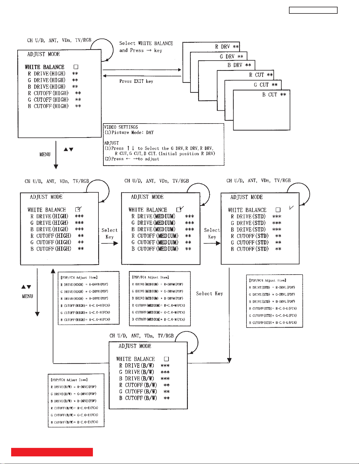
5.7 WHITE BALANCE ADJUSTMENT OSD FLOW DIAGRAM
PT5-G/PW1-H
BACK TO ADJUSTMENTS
30
 Loading...