

Hitachi 42hdm70 Service Manual
YK
No.004E
42HDM70
SERVICE MANUAL
Caution
Be sure to read this manual before servicing. To assure safety from re, electric shock, injury, harmful radiation
and materials, various measures are provided in this HITACHI Plasma display.
Be sure to read cautionary items described in the manual to maintain safety before servicing.
Service Warning
1. Since Panel Module and front Filter are made of glass, handling the broken Module and Filter shall be
taken care sufciently in order not to be injured.
2. Replacing work shall be started after the Panel Module and the AC/DC Power supply become sufciently
cool.
3. Special care shall be taken to the display area in order not to damage its surface.
4. The Panel Module shall not be touched with bare hand to protect its surface from stains.
5. It is recommended to use clean soft gloves during the replacing work in order to protect not only the display area of the Panel Module but also a serviceman himself.
6. The Chip Tube of Panel Module (located upper left of the back and surrounded by frame) and exible
cables connecting Panel glasses to drive circuit PWBs are very weak, so shall be taken care sufciently
not to break. If you break Chip Tube, the Panel doesn’t display anything forever.
(PW1)
Contents
1. Features -------------------------------------------------- 3
2. Specications--------------------------------------------4
3. Service point ---------------------------------------------5
4. Adjustment -----------------------------------------------6
5. Troubleshooting--------------------------------------- 21
6. Self diagnosis function ------------------------------ 28
SPECIFICATIONS AND PARTS ARE SUBJECT TO CHANGE FOR IMPROVEMENT.
7. Block diagram ----------------------------------------- 31
8. Connection diagram --------------------------------- 33
9. Wiring diagram ---------------------------------------- 34
10.Disassembly diagram-------------------------------- 36
11.Replacement parts list------------------------------- 39
Plasma Display
September 2003 Digital Media Division

42HDM70 (PW1)
3
42HDM70 (PW1)
CAUTION FOR SAFETY
Please read this page before repair the monitor.
This page explains to following items for keep the safety of set and prevent to accident during
repair work.
We explain by symbol at happen the damage or injury when took wrong repair.
Warning
Caution
We made the symbol as below, which are kind of following items.
This symbol means "CAUTION"
This symbol means "POSSIBLE to
ELECTRIC SHOCK"
This symbol means "possible to die or heavy damage"
This symbol means "possible to damage or something will break"
This symbol means "MUST"
This symbol means "DO NOT"
WARNING
Should be follows to instructions.
We indicates to cabinet, chassis and parts
by label, which are special attention part.
Please follow to note and [Safety Instructions]
of User’s Manual.
Prevent the electric shock.
Please take care during working because
monitor has high voltage part and power
supply part.
Possible to die if you tough to these place
by miss take.
Please disconnect power plug during
overhaul, reassemble or change parts.
You will die or take damage by electric
shock if you touch to live part.
Use recommended components.
Please use to same characteristic compo-
nent, which is same as previous for your
safety and keep reliability especially marked
by in parts list and circuit diagram.
It is reason of electric shock or fire if you
use non-recommended component.
Should be kept same style of wiring or component.
Monitor uses tubes or tapes, which made
by insulator, and some components are
keep distance from surface of PWB for
safety.
Internal leads kept from hot part or high voltage
part by clamper or styling, so please return to
original condition for prevent to electric shock
or fire.
Should be done safety check after finished.
Every part (removed screws, component
and wiring) should be returned to previous
condition.
Check around repair position for make
damage by miss take and measure the
insulated impedance by meg-ohm meter.
Confirm the value of impedance, that
value is more than 4M ohm.
It is reason for electric shock or fire if that
value is less than 4M ohm.
Nobody can check and repair to the code
and combination circuit of HDCP.
Never remove the shield case, which is
assembled to the code and combination
circuit of HDCP.
2
42HDM70 (PW1)
PRECAUTIONS
● How to clean the plasma screen panel of the monitor
Before cleaning the monitor, turn off the monitor and disconnect the power plug from the power outlet.
To prevent scratching or damaging the plasma screen face, do not knock or rub the surface with sharp or hard
objects. Clean the screen with a soft cloth moistened with warm water and dry with a soft cloth. If it is not
enough, then use a cloth with mild detergent. Do not use harsh or abrasive cleaners.
● How to clean the cabinet of the monitor
Use a soft cloth to clean the cabinet and control panel of the monitor. When excessively soiled dilute a neutral
detergent in water, wet and wring out the soft cloth and afterward wipe with a dry soft cloth.
Never use acid/alkaline detergent, alcoholic detergent, abrasive cleaner, powder soap, OA cleaner, car wax,
glass cleaner, etc. especially because they would cause discoloration, scratches or cracks.
1. Features
● Large-screen, high-definition plasma display panel
The 42-inch color plasma display panel, with a resolution of 1024 (H) x 1024(V) pixels, creates a high-definition,
large-screen (aspect ratio : 16:9) and low-profile flat display. Free from electromagnetic interferences from geo-
magnetic sources and ambient power lines, the panel produces high-quality display images free from color mis-
convergence and display distortion.
● High Performance Digital Processor
A wide range of personal computer signals can be handled, from 640 x 400, 640 x 480 VGA to 1600 x 1200 UXGA.
● Easy-to-use remote control and on screen display system
The remote control included eases the work of setting display controls. Further, the on-screen display system,
displays the status of signal reception and display control settings in an easy-to-view fashion.
● Power saving system
The International ENERGY STAR power saver feature saves power consumption automatically when input
signals are not available.
When connected to a VESA DPMS-compliant PC, the monitor cuts its power consumption while it is idle.
● TruBass
TruBass, SRS and ( ) symbol are trademarks of SRS Labs,Inc.
TruBass technology is incorporated under license from SRS Labs, Inc.
About the Video Unit
The following functions can be obtained by the video unit.
(1) A composite/S terminal and two component terminals have been added. A composite video output terminal is
also provided as a monitoring output.
(2) A wide range of devices other than personal computers can also be connected.
(3) A component input is possible to switch to RGB signals from the Menu screen.
(4) A SCART terminal is also provided for the signal of the European standard. It operates as composite/S/RGB
input terminal, or video output terminal.
3
5
42HDM70 (PW1)
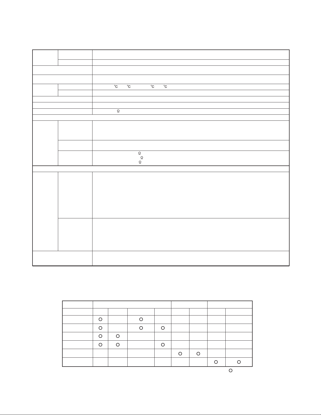
2. Specifications
Panel
Display
dimensions
Approx. 42 inches (922 (H) x 522 (V) mm, diagonal 1059mm)
Resolution
1024 (H) x 1024 (V) pixels
Net dimensions
(excluding Speakers/Stand)
1030 (W) x 636 (H) x 91 (D) mm
Net weight
(excluding Speakers/Stand)
34.9kg
Ambient
conditions
Temperature
Relative humidity
Operating : 20% to 80%, Storage : 20% to 90% (non-condensing)
Power supply
AC100 - 240V, 50/60Hz
Power consumption/at standby
365W / <3W
Audio output
(RGB input)
Input signals
Input terminals
RGB1 DVI input terminal (DVI-D)
RGB1 audio input terminal (3.5mm Stereo Mini Jack)
RGB2 analog RGB input terminal (D-sub 15-pin)
RGB2 audio input terminal (3.5mm Stereo Mini Jack)
Video signals
0.7 V/1.0 Vp-p, analog RGB (Recommended Signal)
480i, 576i, 480p, 576p, 1080i/50, 1080i/60, 720p/60
Sync signals
H/V separate, TTL level [2K ]
H/V composite, TTL level [2K ]
Sync on green, 0.3 Vp-p [75 ]
(Video input)
Input signals
Input terminals
AV1: composite video input terminal (RCA)
AV1: Y PB PR video input terminal (RCA)
AV1: L/R audio input terminal (RCA)
AV2: composite video input terminal (RCA)
AV2: Y/G PB/B PR/R video input terminal (RCA)
AV2: L/R audio input terminal (RCA)
AV3: composite video input terminal (RCA)
AV3: S video input terminal (RCA)
AV3: L/R audio input terminal (RCA)
AV4: composite video / S video / RGB / L/R audio input terminal (Scart)
Video signals
AV1: NTSC-M, PAL-M, PAL-N
AV1: 480i, 576i, 480p, 576p, 1080i/50, 1080i/60, 720p/60
AV2: NTSC-M, PAL-M, PAL-N
AV2: 480i, 576i, 480p, 576p, 1080i/50, 1080i/60, 720p/60, RGB
AV3: NTSC-M, PAL-M, PAL-N
AV4: NTSC-M, PAL-M, PAL-N
AV4: RGB
Video output Signal
OUTPUT (MONITOR): composite video monitor-output terminal (RCA)
OUTPUT (MONITOR): L/R audio monitor- output terminal (RCA)
AV4: composite video / L/R audio monitor-output terminal (SCART)
Operating : 5℃ to 35℃, Storage : 0℃ to 40℃
12W + 12W (6Ω)
Terminal RCA/SCART DVI D-sub
Signal CVBS S-video Component RGB PC STB RGB Component
AV1
AV2
AV3
AV4
RGB1
RGB2
( :Available)
42HDM70 (PW1)
Applicable video signals for each input terminal
4
42HDM70 (PW1)
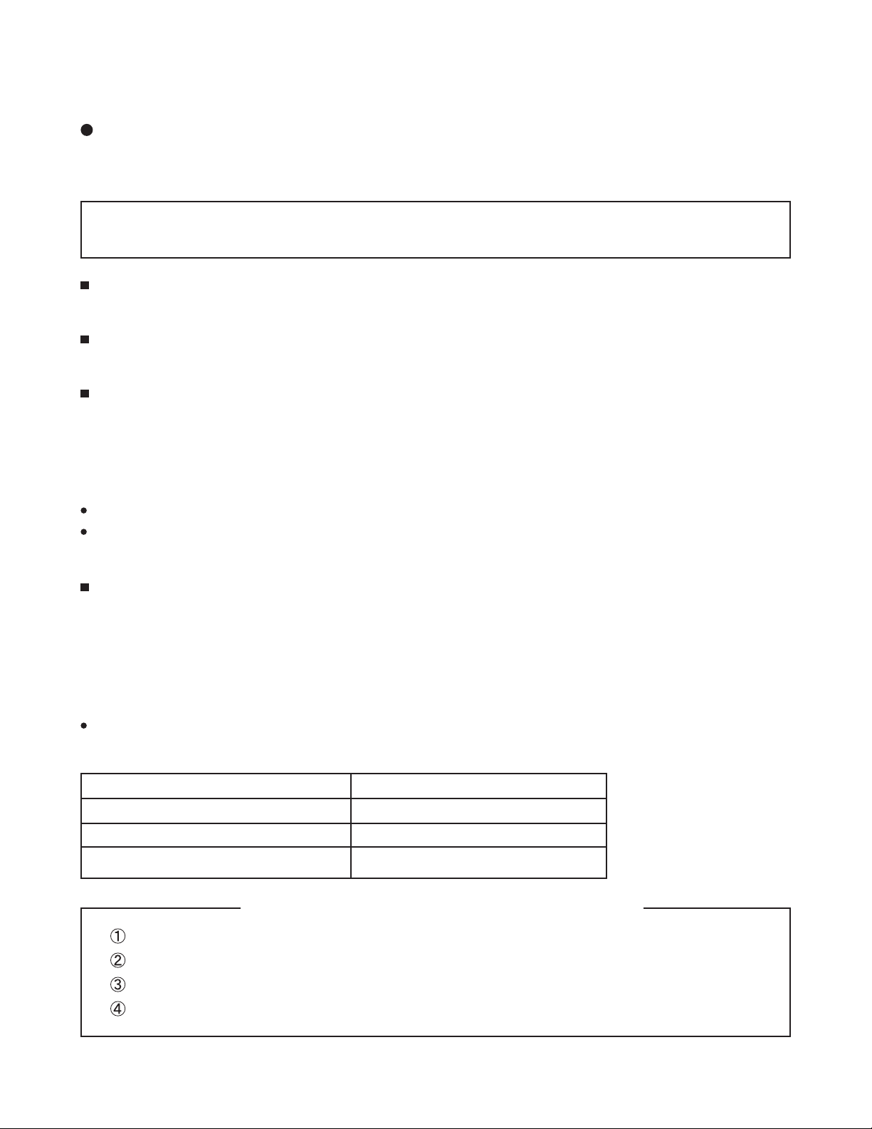
3. Service points
Lead free solder
This product uses lead free solder (unleaded) to help preserve the environment. Please read these instructions
before attempting any soldering work.
Caution: Always wear safety glasses to prevent fumes or molten solder from getting into the eyes. Lead free
solder can splatter at high temperatures (600˚C).
Lead free solder indicator
Printed circuit boards using lead free solder are engraved with an "F."
Properties of lead free solder
The melting point of lead free solder is 40-50˚C higher than leaded solder.
Servicing solder
Solder with an alloy composition of Sn-3.0Ag-0.5Cu or Sn-0.7Cu is recommended.
Although servicing with leaded solder is possible, there are a few precautions that have to be taken. (Not taking
these precautions may cause the solder to not harden properly, and lead to consequent malfunctions.)
Precautions when using leaded solder
Remove all lead free solder from soldered joints when replacing components.
If leaded solder should be added to existing lead free joints, mix in the leaded solder thoroughly after the lead
free solder has been completely melted (do not apply the soldering iron without solder).
Servicing soldering iron
A soldering iron with a temperature setting capability (temperature control function) is recommended.
The melting point of lead free solder is higher than leaded solder. Use a soldering iron that maintains a high
stable temperature (large heat capacity), and that allows temperature adjustment according to the part being
serviced, to avoid poor servicing performance.
Recommended soldering iron:
Soldering iron with temperature control function (temperature range: 320-450˚C)
Recommended temperature range per part:
Part Soldering iron temperature
Mounting (chips) on mounted PCB 320˚C±30˚C
Mounting (chips) on empty PCB 380˚C±30˚C
Chassis, metallic shield, etc. 420˚C±30˚C
The PWB assembly which has used lead free solder
FILTER PWB, SW PWB, LED/RECEIVER PWB, TACT SW PWB, SP TERMINAL(L/R) PWB
AUDIO PWB, JOINT PWB
VIDEO PWB
FORMATTER PWB
5

42HDM70 (PW1)
7
42HDM70 (PW1)
4. Adjustment
● How to get to Adjustment mode
Using the front control buttons with the set turned off (standby) can activate it.
Press the SUB-POWER( ) button, INPUT SELECT( ) button and button at the same time, and hold for
more than 5 seconds.
The set turns on in adjustment mode with OSD.
● Changing data and Selecting Adjustment code
When the set is in adjustment mode, the cursor , , , and OK buttons of the remote control or front panel
may be used as the adjustment keys.
, buttons are used for selecting adjustment code.
, buttons are used for changing data values.
OK button is used for confirming the data.
After finishing the necessary adjustment press MENU button. Adjustment mode is released and the set returns to
normal condition.
● Memory Initialize operation
NOTE: The execution of this function returns the adjustment codes to the preset values, therefore, adjustment
data will be lost.
Procedure
(1) Enter Adjustment Mode.
(2) Select MEMORY INIT adjustment code (No.704) and change the data value from 0 to 1.
(3) Activate MEMORY INIT by pressing OK button for more than 3 seconds.
(4) Select No.374 and change data value from 1 to 0.
(5) Check that the receiving channel goes to AV1. Unit is set to preset values.
6
42HDM70 (PW1)
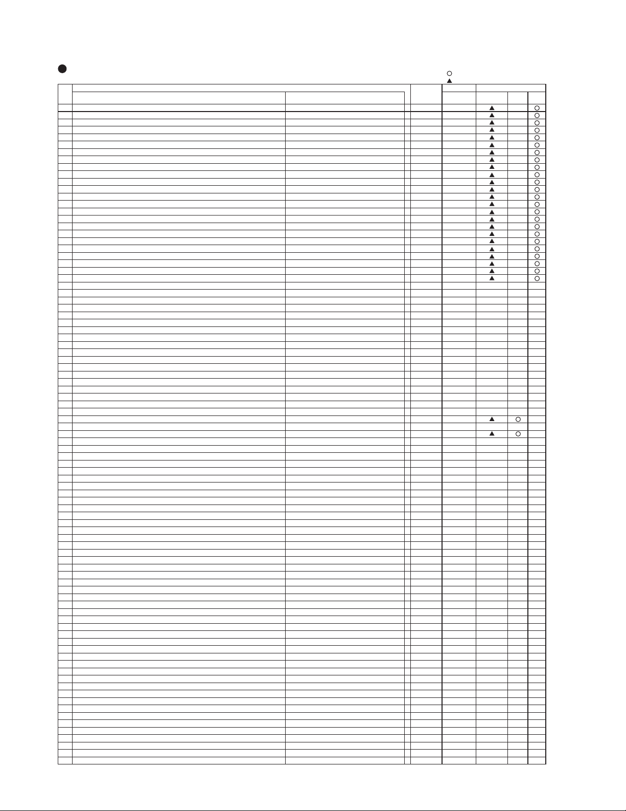
: should be adjusted
: should be followed previous data
Function Maximum
Adjustment Items Mode Value 42"
FORMATTER
PWB
VIDEO
PWB
PDP
Panel
0 R DRIVE1 [TV/VIDEO/DSUB-COMP] COOL 255 255
1 G DRIVE1 [TV/VIDEO/DSUB-COMP] COOL 255 255
2 B DRIVE1
[TV/VIDEO/DSUB-COMP] COOL 255 255
3 R DRIVE2 [TV/VIDEO/DSUB-COMP] NORMAL 255 255
4 G DRIVE2
[TV/VIDEO/DSUB-COMP] NORMAL 255 255
5 B DRIVE2 [TV/VIDEO/DSUB-COMP] NORMAL 255 255
6 R DRIVE3 [TV/VIDEO/DSUB-COMP] WARM 255 255
7 G DRIVE3
[TV/VIDEO/DSUB-COMP] WARM 255 255
8 B DRIVE3 [TV/VIDEO/DSUB-COMP] WARM 255 255
9 R DRIVE4 [TV/VIDEO/DSUB-COMP] BLACK & WHITE 255 255
10 G DRIVE4
[TV/VIDEO/DSUB-COMP] BLACK & WHITE 255 255
11 B DRIVE4 [TV/VIDEO/DSUB-COMP] BLACK & WHITE 255 255
12 R DRIVE1 [DVI-PC/DVI-STB/DSUB-RGB] COOL 255 255
13 G DRIVE1
[DVI-PC/DVI-STB/DSUB-RGB] COOL 255 255
14 B DRIVE1 [DVI-PC/DVI-STB/DSUB-RGB] COOL 255 255
15 R DRIVE2 [DVI-PC/DVI-STB/DSUB-RGB] NORMAL 255 255
16 G DRIVE2 [DVI-PC/DVI-STB/DSUB-RGB] NORMAL 255 255
17 B DRIVE2 [DVI-PC/DVI-STB/DSUB-RGB] NORMAL 255 255
18 R DRIVE3
[DVI-PC/DVI-STB/DSUB-RGB] WARM 255 255
19 G DRIVE3 [DVI-PC/DVI-STB/DSUB-RGB] WARM 255 255
20 B DRIVE3 [DVI-PC/DVI-STB/DSUB-RGB] WARM 255 255
21 R DRIVE4
[DVI-PC/DVI-STB/DSUB-RGB] BLACK & WHITE 255 255
22 G DRIVE4 [DVI-PC/DVI-STB/DSUB-RGB] BLACK & WHITE 255 255
23 B DRIVE4 [DVI-PC/DVI-STB/DSUB-RGB] BLACK & WHITE 255 255
24 Black Level(RGB_AMP) TV/VIDEO 254 127
25 Black Level(RGB_AMP) PC 254 127
26 Reference Amplitude(RGB_AMP) TV/VIDEO 254 127
27 Reference Amplitude(RGB_AMP) PC 254 127
28 Display for Max. Amplitude Level Main - 29 Display for Max. Amplitude Level SUB - 30 SUB
_
CONTRAST(RF) MAIN 15 8
31 SUB_CONTRAST (AV1) MAIN/SUB COMPOSITE mode 15 7
32 SUB
_
CONTRAST(RF) SUB 15 8
33 SUB_CONTRAST (AV4) MAIN/SUB COMPOSITE mode 15 7
34 SUB
_
COLOR(VIDEO-PAL/SECAM) MAIN 15 6
35 SUB
_
COLOR(RF-PAL/SECAM) MAIN 15 8
36 SUB_COLOR(VIDEO-NTSC) MAIN 15 8
37 SUB_COLOR(RF-NTSC) MAIN 15 6
38 SUB
_
COLOR(VIDEO-PAL/SECAM) SUB 15 8
39 SUB_COLOR(RF-PAL/SECAM) SUB 15 8
40 SUB_COLOR(VIDEO-NTSC) SUB 15 8
41 SUB_COLOR(RF-NTSC) SUB 15 8
42 TINT(VIDEO) MAIN 63 33
43 TIN
T(RF) MAIN 63 33
44 TINT(VIDEO) SUB 63 33
45 TINT(RF) SUB 63 33
46 S_B-Y_ADJ MAIN 15 8
47 S_R-Y_ADJ MAIN 15 8
48 S_B-Y_ADJ SUB 15 8
49 S_R-Y_ADJ SUB 15 8
50 BPF_Q (4.43MHz) MAIN 3 3
51 BPF_f0 (4.43MHz) MAIN 3 1
52 Y_DL (4.5MHz) For Asia MAIN 10 5
53 Y_DL (5.5MHz PAL/NTSC4.43) For Asia MAIN 10 3
54 Y_DL (5.5MHz SECAM) For Asia MAIN 10 0
55 Y_DL (6.0PAL/NTSC4.43) For Asia MAIN 10 9
56 Y_DL (6.0SECAM) For Asia MAIN 10 9
57 Y
_
DL (VIDEO PAL/NTSC4.43) MAIN 10 6
58 Y_DL (VIDEO SECAM) MAIN 10 8
59 Y_DL (VIDEO NTSC) MAIN 10 6
60 BELL_f0 MAIN 1 0
61 Y_OUT_LEVEL (VIDEO) MAIN 63 13
62 Free
63 Y_OUT_LEVEL (TEXT) MAIN 63 0
64 C_OUT_LEVEL (VIDEO) MAIN 63 7
65 Free
66 C_OUT_LEVEL (TEXT) MAIN 63 0
67 Y_OUT_LEVEL (TEXT) SUB 63 12
68 Y_OUT_LEVEL (VIDEO) SUB 63 13
69 Free
70 C_OUT_LEVEL (TEXT) SUB 63 7
71 C_OUT_LEVEL (VIDEO) SUB 63 7
72 Free
73 BPF_Q (4.43MHz) SUB 3 3
74 BPF_f0 (4.43MHz) SUB 3 1
75 Y_DL (4.5MHz) For Asia SUB 10 5
76 Y_DL (5.5MHz PAL/NTSC4.43) For Asia SUB 10 2
77 Y_DL (5.5MHz SECAM) For Asia SUB 10 0
78 Y_DL (6.0PAL/NTSC4.43) For Asia SUB 10 7
79 Y_DL (6.0SECAM) For Asia SUB 10 10
80 Y
_
DL (VIDEO PAL/NTSC4.43) SUB 10 8
81 Y_DL (VIDEO SECAM) SUB 10 6
82 Y_DL (VIDEO NTSC) SUB 10 5
83 BELL_f0 SUB 1 0
84 C_TRAP_SW (COMB=OFF-PAL/NTSC4.43/NTSC3.58) MAIN 1 0
85 C_TRAP_SW (COMB=OFF-PAL/NTSC4.43/NTSC3.58) SUB 1
1
0
86 MVM(VIDEO
) - 0
87 AFC_GAIN (AV00) - 3 0
88 AFC_GAIN (AV1) - 3 0
Defaul
t Changed Component
ADJ.
No.
Service
adjustment items by I2C-bus control
7
42HDM70 (PW1)
9
42HDM70 (PW1)
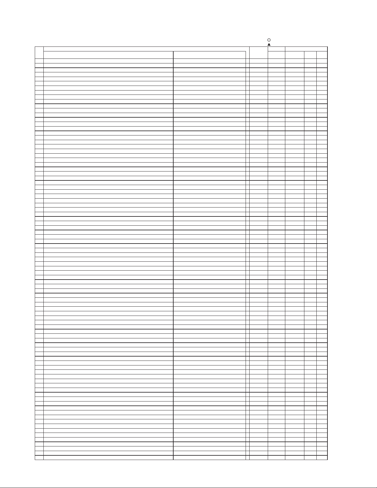
: should be adjusted
: should be followed previous data
Function Maximum
Adjustment Items Mode Value 42"
VIDEO
PWB
PDP
Panel
89 AFC_GAIN (AV2) - 0
90 AFC_GAIN (AV3) - 0
91 AFC_GAIN (AV4) - 3
3
3
0
92 S_INHBT - 1
1
0
93 S_ID - 0
94 S_GP - 3 0
95 S_V_ID - 1 0
96 BELL/HPF - 3 3
97 Cb offset1 MAIN 15 8
98 Cr offset1 MAIN 15 8
99 Cb offset1 SUB 15 8
100 Cr offset1 SUB 15 8
101 Sharpness Gain(VIDEO) PAL MAIN 15 8
102 Sharpness Gain(RF) MAIN 15 8
103 Sharpness EQ(4.5MHz) MAIN 3 1
104 Sharpness EQ(5.5MHz) MAIN 3 1
105 Sharpness EQ(6.0/6.5MHz) MAIN 3 1
106 Sharpness EQ(VIDEO) MAIN 3 1
107 Sharpness f0(VIDEO) PAL MAIN 3 2
108 Sharpness f0(RF) MAIN 3 2
109 Sharpness Gain(VIDEO) PAL SUB 15 9
110 Sharpness Gain(RF) SUB 15 10
111 Sharpness EQ(4.5MHz) SUB 3 1
112 Sharpness EQ(5.5MHz) SUB 3 1
113 Sharpness EQ(6.0/6.5MHz) SUB 3 1
114 Sharpness EQ(VIDEO) SUB 3 1
115 Sharpness f0(VIDEO) PAL SUB 3 2
116 Sharpness f0(RF) SUB 3 2
117 LPF MAIN 1 0
118 LPF SUB 1 0
119 SECAM D-Trap MAIN/SUB 1 1
120 FILTER SW(RF) MAIN 1 0
121 FILTER SW(RF) SUB 1 0
122 NTSC Comb(Comb off) SUB 1 1
123 HS Phase MAIN 1 0
124 HS Phase SUB 1 0
125 P/N ID MAIN 1 0
126 P/N ID SUB 1 0
127 Y/C_SEP_MODE (COMB=OFF-PAL) - 3 0
128 Y-Pf0 - 1 0
129 Y-EQ_GAIN - 3 2
130 Y-EQ/N.C_LIM - 3 0
131 Y-LPF - 1 0
132 V-EMPH_GAIN - 7 1
133 V-EMPH_N.L - 7 3
134 V-EMPH_CORE - 3 3
135 D RANGE - 1 0
136 DY_GAIN MAIN NTSC mode 15 9
137 DC_GAIN MAIN NTSC mode 15 6
138 VAP_GAIN MAIN NTSC mode 7 2
139 VAP_INV MAIN NTSC mode 31 10
140 YH_CORE MAIN NTSC mode 3 0
141 YHCGAIN MAIN NTSC mode 1 1
142 CDL MAIN NTSC mode 7 3
143 YNRK MAIN NTSC mode 1 1
144 YNRINV MAIN NTSC mode 1 0
145 YNRLIM MAIN NTSC mode 3 1
146 CNRK 1 1
147 CNRINV 1 0
148 CNRLIM 3 1
149 YPFG 15 10
150 SEPA_LEVEL 480i/576i 3 2
151 SEPA_LEVEL 480p/576p 3 2
152 SEPA_LEVEL 1080i_50 3 2
153 SEPA_LEVEL 1080i_60/720p 3 2
154 AUTO_FM/AM(D11-D8) - 15 2
155 AUTO_FM/AM(D7-D0) - 254 189
156 A2_THRESHOLD(D11-D8) - 15 0
157 A2_THRESHOLD(D7-D0) - 254 112
158 PRE_AM except 4.5MHz(except BIL/STE) 254 17
159 VOL_SCART1 (D15-D8) - 254 115
160 VOL_SCART1 (D7-D5) - 7 0
161 PRE_SCART - 254 31
162 PRE_FM 4.5MHz(JAPAN) 254 34
163 PRE_FM 4.5MHz(except BTSC-SAP) 254 32
164 PRE_FM 4.5MHz(BTSC-SAP) 254 60
165 PRE_FM 4.5MHz(KOREA-except BIL/STE) 254 19
166 PRE_FM 4.5MHz(KOREA-BIL/STE) 254 34
167 PRE_FM except 4.5MHz(except BIL/STE) 254 17
168 PRE_FM except 4.5MHz(BIL/STE) 254 27
169 PRE_NICAM - 254 57
170 Screen Saver -Picture shift amount 0:1pixel 1:2pixels 2:3pixels 2 0
171 Thermal Sensor available
0:NO 1:YES
1 0
172 Video In
put Function available
0:NO 1:YES
0:NO 1:YES
1 1
173 Screen Saver -Picture Shift direction 0:dia 1:cross 2:up/down 3:left/right 3 0
174 AUDIO Function available 1 1
175 Remouto Function available
0:NO, 1: YES
1 1
176 Power Save On/Off Setting at Initialize,Reset and Shipping 0:Change 1: Don't Change 1 0
177 DVI-STB/RGB-COMPONENT Function available 0: NO, 1: YES 1 0
Defaul
t Changed Component
ADJ.
No.
FORMATTER
PWB
8
42HDM70 (PW1)
: should be adjusted
: should be followed previous data
Function Maximum
Adjustment Items Mode Value 42"
VIDEO
PWB
PDP
Panel
178 Free
179 Free
180 Terminal Mode Function available 0:Not Available, 1:Available RS232C 1 0
181 Free
182 AGC_LEVEL AGCL ALL Mode 3 0
183 TEXT H sync delay - 127 0
184 TEXT V sync delay - 127 74
185 TEXT_H_POSITION - 254 42
186 TEXT_V_POSITION - 254 38
187 Lower Limits value for Sync Detect of 2ms interval For AFC at TV mode 254 25
188 Upper Limits Value for Sync Detect of 2ms interval For AFC at TV mode 254 40
189 Lower Limits value for Sync Detect of 2ms interval For Free Running at TV mode 254 30
190 Upper Limits Value for Sync Detect of 2ms interval For Free Running at TV mode 254 45
191 Lower Limits value for Sync Detect of 2ms interval For AUTO OFF at TV mode 254 25
192 Upper Limits Value for Sync Detect of 2ms interval For AUTO OFF at TV mode 254 35
193 Lower Limits value for Sync Detect of 2ms interval For Free Running at AV mode 254 30
194 Upper Limits Value for Sync Detect of 2ms interval For Free Running at AV mode 254 45
195 Counting time for discrimination of fV (TB1274) - 31 2
196 Free 1 0
197 Counting time for discrimination of Sync. (M30625/TA1370) - 31 2
198 Input Source of fV/fH judgment (0:M30625,1:TA1370) Component Mode 1 0
199 Counting time for discrimination of fV (M30625/TA1370) - 31 2
200 Y_DL (6.5MHz PAL/NTSC4.43) For Asia Main 10 7
201 Y_DL (6.5MHz SECAM) For Asia Main 10 10
202 Y_DL (6.5MHz PAL/NTSC4.43) For Asia Sub 10 4
203 Y_DL (6.5MHz SECAM) For Asia Sub 10 10
204 PDP-BLK ON/OFF 1:ON, 0:OFF 1 0
205 Counting time for discrimination of fH (M30625/TA1370) - 31 2
206 Sharpness f0(L) Sub 3 2
207 NJW1320_OUT1_GAIN VIDEO PWB 1 0
208 NJW1320_OUT2_GAIN VIDEO PWB 1 0
209 Sharpness f0(L') Sub 3 2
210 AFC_GAIN (Except AV00 mode) Except AV00 mode 3 0
211 Timer Correction
(for error of ceramic-filter osc.freq.) 62 34
212 Brightness Center (CM)
NT2/NT3/HD2/HD3/PAL2/PAL3/HD9/HD10/NT4/PAL4
254 128
213 Brightness Center (CM) HD1/HD4/HD5/HD6/HD7/HD8 254 124
214 Brightness Center (CM) MULTI PICTURE/NT1/PAL1 254 128
215 Free
216 Contrast Center (CM) TV/VIDEO(AV1/AV4 mode) 254 137
217 Free
218 Color Center (CM) NT1/NT2/NT4/HD3/HD4/HD6/PAL4 127 80
219 Color Center (CM) PAL1/PAL2/HD8/HD9 127 80
220 Color Center (CM) NT3/HD1/HD2/HD5/PAL3/HD7/HD10 127 80
221 Tint Cente
r (CM) PAL1 254 118
222 Tint Center (CM) NT1/NT2/NT4/HD3/HD4/HD6 254 120
223 Tint Center (CM) PAL2/HD8/HD10/PAL4 254 115
224 Tint Cente
r (CM) NT3/HD1/HD2/HD5/PAL3/HD7/HD9 254 124
225 Center of Sharpness (HV Enhancer Gain for Y) For Europe TV 31 19
226 Center of Sharpness (HV Enhancer Gain for Y) For Europe VIDEO 31 18
227 Center of Sharpness (HV Enhancer Gain for Y) For Europe HD5/HD6 31 11
228 Center of Sharpness (HV Enhancer Gain for Y) For Europe HD1/HD4/HD7/HD8 31 7
229 Center of Sharpness (HV Enhancer Gain for Y) For Europe HD2/HD3/HD9/HD10 31 15
230 Center of Sharpness (HV Enhancer Gain for Y) For Europe NT2/NT3/PAL2/PAL3/NT4/PAL4 31 15
231 Center of Sharpness (HV Enhancer Gain for Y) For Europe TEXT(2 picture) 31 7
232 Maximum Value of Contrast at REAL/NORMAL mode 254 188
233 Offset Value of Contrast data at SPLIT mode 120 90
234 Offset value of gain for Black Stretch function except OFF/LOW/HIGH 63 33
235 Demonstration [White] 0-3:None 4:0 5:+10W 6:+20W 7:+30W Mode(common) 7 5
236 Demonstration 0:Normal 1:Peak Mode 1 237 Demonstration [Middle] 0:+0W 1:+10W 2:+20W 3:+30W Mode(common) 3 3
238 Demonstration 0:Normal 1:Peak Mode 1 0
239 Horizontal Enhance TEXT 3 3
240 YNR Input Level at Low level for DVI-STV Mode 1080i-60/1080i-50/720p-60 7 2
241 YNR Input Level at Low level for DVI-STV Mode 480i/480p/576i/576p/VGA 7 2
242 CNR Input Level at Low level for DVI-STV Mode 1080i-60/1080i-50/720p-60 7 2
243 CNR Input Level at Low level for DVI-STV Mode 480i/480p/576i/576p/VGA 7 2
244 Vertical Enhance TEXT 3 3
245 Demonstration Mode 0:off 1:on 1 0
246 Free
247 Free
248 HV Enhancer Gain for C TEXT 31 0
249 YNR(NR) Input Level RF Mode 7 1
250 YNR Input Level at Low level for AV1-4 Mode VIDEO 7 3
251 YNR Input Level at Low level for AV1-4 Mode NT2/NT3/PAL2/PAL3/NT4/PAL4 7 3
252 YNR Input Level at Low level for AV1-4 Mode HD1/HD4/HD5/HD6/HD7/HD8 7 3
253 YNR Input Level at Low level for AV1-4 Mode HD2/HD3/HD9/HD10 7 3
254 CNR Input Level at Low level for AV1-4 Mode VIDEO 7 3
255 CNR Input Level at Low level for AV1-4 Mode NT2/NT3/PAL2/PAL3/NT4/PAL4 7 3
256 CNR Input Level at Low level for AV1-4 Mode HD1/HD4/HD5/HD6/HD7/HD8 7 3
257 CNR Input Level at Low level for AV1-4 Mode HD2/HD3/HD9/HD10 7 3
258 Heat APC function available
0:NO, 1 : YES 1 1
259 Gamma SW (0:1.0 1:2.2 2:2.8) TV/VIDEO 2 1
260 Gamma SW (0:1.0 1:2.2 2:2.8) DVI-PC/DVI-STB/DSUB-RGB 2 1
261 Select for APC function 1 0
262 "CCFMD" function TV/VIDEO 1 0
263 "CCFMD" function DVI-PC/DVI-STB/DSUB-RGB 1 0
264 NTSC/EBU(CCFORM)
NT1/NT2/HD3/HD4/HD6/HD8/HD10/PAL1/PAL2
1 0
265 NTSC/EBU(CCFORM)
TV/VIDEO/NT3/PAL3/HD1/HD2/HD5/HD7/HD9/NT4/PAL4
1 0
266 NTSC/EBU(CCFORM) DVI-PC/DVI-STB/DSUB-RGB 1 0
Defaul
t Changed Component
ADJ.
No.
FORMATTER
PWB
9

42HDM70 (PW1)
11
42HDM70 (PW1)
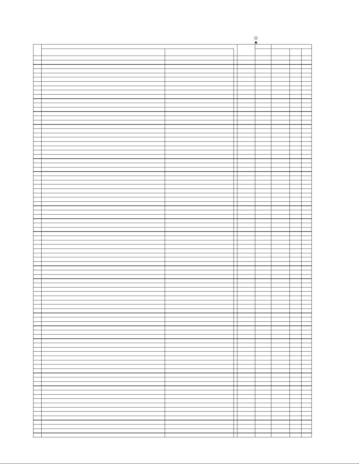
: should be adjusted
: should be followed previous data
Function Maximum
Adjustment Items Mode Value 42"
VIDEO
PWB
PDP
Panel
267 Correction for Tracking (DCBON) TV/VIDEO-Color Temp. : COOL 1 0
268 Correction for Tracking (DCBON) TV/AV-Col. Temp. : Nor/War 1 1
269 Correction for Tracking (DCBON) DVI-PC/DVI-STB/DSUB-RGB 1 1
270 Color Temp. Correction 3 0
271 Typical Value of Contrast OSD DYNAMIC 31 31
272 PC Power Save function (0:Impossible 1:Possible) 1 1
273 Waite Time for POWER SAVE function (s) VIDEO/PC 254 15
274 Lower Limits value for Sync Detect of 2ms interval For Power Save at AV mode 254 5
275 Upper Limits Value for Sync Detect of 2ms interval For Power Save at AV mode 254 200
276 Horizontal Position of OSD 60Hz 15 7
277 Vertical Position of OSD 60Hz 15 7
278 PinP Function 0:PinP, 1:Infomation1, 2:Infomaiton Split 2 0
279 Select for WIDE Mode 1 1
280 Temperature for FAN Restart (Temp_High) 254 58
281 Temperature for FAN Stop (Temp_Low) 254 55
282 Internal Tem
perature Display 125 283 PDP micom Version Display 255 284 Total Operating Hours of PDP panel 65535 285 Initialize function 0:Keep data, 1:Initialize
No.0-No.23,30-33,42-45,289,293,294Adj No.701-703,
1 0
286 L standard PLL gating HIGH [Europe model] 1 0
287 Select for APC output [Except Europe model] Main FE 2 1
288 Other New function (Shin Doga mode) 0:Off, 1:On 50Hz 1 0
289 AGC adjustment (MFE) [Except Europe model] MAIN 63 50
290 AGC adjustment (MFE) [Europe model] MAIN 63 20
291 AGC INPUT(MFE) MAIN - 292 Other New function (Shin Doga mode) 0:Off, 1:On 70Hz(PC) 1 0
293 SUB CONTRAST AV2 MAIN/SUB COMPOSITE mode 15 8
294 SUB CONTRAST AV3 MAIN/SUB COMPOSITE mode 15 8
295 Contrast Center (CM) AV2 254 137
296 Contrast Center (CM) AV1 254 137
297 Brightness center (CM) offset AV2 254 127
298 Brightness center (CM) offset AV1 254 127
299 Other New function (Shin Doga mode) 0:Off, 1:On 60Hz 1 1
300 3D ON/OFF 0:ON,1:OFF(Through) 1 0
301 Input Select of TA1370 0:HD1/VD1,1:HD3/VD3 Main/Sub 1 0
302 Sharpness Gain(RF/NR) Main/Sub 15 3
303 3Line Y/C Main- Sub SW 0:Main, 1: Sub 1 0
304 Offset Value(+/-) of Upper Limit (for TB1274:SUB-CONT) Single Picture mode 18 2
305 Offset Value(+/-) of Upper Limit (for FC :RGB-AMP ) Multi Picture mode 18 2
306 Reference Amplitude(RGB_AMP) Multi Picture mode 254 127
307 Component Frq.(fH) Setup (0:28/31/33/45KHz,1:28/31/45KHz) 1 0
308 Terget value of White peak Adj. Single Picture mode 237 235
309 Sharpness Gain(S VIDEO) Main 15 7
310 Sharpness Gain(S VIDEO) Sub 15 7
311 Select color control (0: Asia, 1: South America) Main/Sub 1 0
312 Sharpness Gain Main(N-PAL) 15 8
313 Sharpness f0 Main(N-PAL) 3 2
314 Sharpness Gain Sub (N-PAL) 15 9
315 Sharpness f0 Sub (N-PAL) 3 2
316 Delay Time ON/OFF for Lipsync circuit 0:Off, 1:On 1 1
317 Sync Mode SW 7 0
318 Set Sound System at Auto mode of Sound Sys. (0:auto,1:4.5MHz) Main/Sub 1 0
319 Power Restart by cancelling reset from Power Save Mode in PC input 0:keep last condition 1:restart 1 0
320
Change Europe Model for Destination of North America (OSD, Wide Mode etc.) available
0:NO 1:YES(DAY/NIGHT etc.) 1 1
321 Count Souce for ON/OFF Timer 0:MCU-250ms, 1:AC-50/60Hz 1 0
322 Wide Mode Selection for Europe (Normal: 5 modes, For Service: 10 modes) 0:Normal 1:For Service 1 0
323 Forced AVC type available 0:Normal type , 1: Forced AVC type 1 0
324 Sharpness Gain Main(M-PAL) 15 8
325 Sharpness f0 Main(M-PAL) 3 2
326 Sharpness Gain Sub (M-PAL) 15 9
327 Sharpness f0 Sub (M-PAL) 3 2
328 CNR Input Level at Low level for Dsub Comp. Mode NT2/NT3/PAL2/PAL3/NT4/PAL4 7 2
329 CNR Input Level at Low level for Dsub Comp. Mode HD1/HD4/HD5/HD6/HD7/HD8 7 2
330 CNR Input Level at Low level for Dsub Comp. Mode HD2/HD3/HD9/HD10 7 2
331 Sharpness Gain(VIDEO) NTSC3.58 MAIN 15 9
332 Sharpness f0(VIDEO) NTSC3.58 MAIN 3 2
333 Sharpness Gain(VIDEO) NTSC3.58 SUB 15 8
334 Sharpness f0(VIDEO) NTSC3.58 SUB 3 2
335 Sharpness Gain(VIDEO) SECAM,B/W MAIN 15 10
336 Sharpness f0(VIDEO) SECAM,B/W MAIN 3 2
337 Sharpness Gain(VIDEO) SECAM,B/W SUB 15 8
338 Sharpness f0(VIDEO) SECAM,B/W SUB 3 2
339 Sharpness Gain(VIDEO) NTSC4.43 MAIN 15 9
340 Sharpness f0(VIDEO) NTSC4.43 MAIN 3 2
341 Sharpness Gain(VIDEO) NTSC4.43 SUB 15 8
342 Sharpness f0(VIDEO) NTSC4.43 SUB 3 2
343 Brightness Limitted Function of PANEL [APSON] 1 1
344 VsVa WAIT TIMER [RISTIM] 15 5
345 CONTRAST initial value Panel Life -Extend1 127 93
346 Correcting Time Interval Panel Life -Extend1 127 10
347 CONTRAST additional value Panel Life -Extend1 127 1
348 CONTRAST initial value Panel Life -Extend2 127 63
349 Correcting Time Interval Panel Life -Extend2 127 6
350 CONTRAST additional value Panel Life -Extend2 127 1
351 L_PLL.GAIN 1 0
352 Free
353 Free
354 Free
355 Free
Defaul
t Changed Component
ADJ.
No.
FORMATTER
PWB
10

42HDM70 (PW1)
: should be adjusted
: should be followed previous data
Function Maximum
Adjustment Items Mode Value 42"
VIDEO
PWB
PDP
Panel
356 SEPA_LEVEL_DSUB 480i/576i 3 2
357 SEPA_LEVEL_DSUB 480p/576p 3 2
358 SEPA_LEVEL_DSUB 1080i_50 3 2
359 SEPA_LEVEL_DSUB 1080i_60/720p 3 2
360 HD-PHASE_DSUB 480i/576i 63 20
361 HD-PHASE_DSUB 480p/576p 63 20
362 HD-PHASE_DSUB 1080i_50 63 20
363 HD-PHASE_DSUB 1080i_60/720p 63 20
364 Y_DL (L) MAIN 10 4
365 Y_DL (L') MAIN 10 4
366 Y_DL (L) Sub 10 1
367 Y_DL (L') Sub 10 1
368 Sharpness Gain(L) MAIN 15 10
369 Sharpness Gain(L') MAIN 15 10
370 Sharpness Gain(L) SUB 15 8
371 Sharpness Gain(L') SUB 15 8
372 Sharpness f0(L) MAIN 3 2
373 Sharpness f0(L') MAIN 3 2
374 BURN-IN enable/ disenable 0:Disenable, 1:Enable 1 1
375 BURN-IN mode 2 2
376 CM_THRESHOLD (D15-D8) - 254 0
377 CM_THRESHOLD (D7 -D0) - 254 36
378 Sharpness Gain(RF M) MAIN 15 11
379 Sharpness Gain(RF M) Sub 15 11
380 Sharpness f0 (RF M) Main 3 2
381 Sharpness f0 (RF M) SUB 3 2
382 Counting Value of 2ms Sync.Detect MAIN - 383 Counting Value of 2ms Sync.Detect SUB - 384 TB1274 Read Data(00h) Main - 385 TB1274 Read Data(01h) Main - 386 TB1274 Read Data(00h) Sub - 387 TB1274 Read Data(01h) Sub - 388 MSP Read Data (CNTROL ) (D15-D8 ) - 389 MSP Read Data (CNTROL ) (D7 -D0 ) - 390 MSP Read Data (STANDARD_RES) (D15-D8 ) - 391 MSP Read Data (STANDARD_RES) (D7 -D0 ) - 392 MSP Read Data (STATUS ) (D15-D8 ) - 393 MSP Read Data (STATUS ) (D7 -D0 ) - 394 TA1370G Read Data(00h) VIDEO PWB - 395 TA1370G Read Data(01h) VIDEO PWB - 396 TA1370G Read Data(00h) FORMATTER PWB - 397 TA1370G Read Data(01h) FORMATTER PWB - 398 uPD64084 Read Data(00H) - 399 uPD64084 Read Data(01h) - 400 Language (Refer to below) 6 0
401 Hotel Mode(0:No,1:Yes) 1 0
402 Analog Data (0:Keep EEPROM,1:Not Keep to EEPROM) 1 0
403 Maximum Volume Limit 63 63
404 Power Mode(0:Last mode, 1:Pos1, 2:V1, 3:V2, 4:V3, 5:V4) 5 0
405 Channel Select(0:CCIR, 1:CHINA) 1 0
406 Auto_sound 4.5 (0:Korea, 1:BTSC, 2:Japan) 2 0
407 T/TEXT(0: None, 1:Yes) 1 1
408 TEXT Language 7 0
409 IIC BUS Data/Clock Open(0:Close, 1:Open) 1 0
410 Channel Preset(0:VESTEL, 1:GIFU, 2:HAMA, 3:HFDM,4:AUSTRALIA) 4 1
411 Detect and Display Tele-Cinema (0:normal 1:Tele-Cinema) - 412 V FREQ 60Hz Force (0:None, 1:Yes) Main/Sub 1 0
413 COLOR SYSTEM CONTROL-MODE
(0:BW, 2:3.58NTSC, 3:4.43NTSC, ) Main - 414 COLOR SYSTEM CONTROL-MODE(0:BW, 2:3.58NTSC, 3:4.43NTSC, ) Sub - 415 Horizontal Filter SW [HHPF0] NTSC 1 0
416 Enhancer Gain [HHPF1] PAL 1 0
417 Enhancer Gain [HHPF2] HD 1 0
418 Horizontal Coring Level (Enhancer Gain) AS[HECOR0_PO] NT1-RF 15 1
419 Horizontal Coring Level (Enhancer Gain) AS[HECOR1_PO] PAL1-RF / Multi picture 15 1
420 Horizontal Coring Level (Enhancer Gain) [HECOR2_PO] NT1-Video 15 1
421 Horizontal Coring Level (Enhancer Gain) [HECOR3_PO] PAL1-Video 15 1
422 Horizontal Coring Level (Enhancer Gain) [HECOR4_PO] NT2/NT3/NT4/PAL2/PAL3/PAL4 15 1
423 Horizontal Coring Level (Enhancer Gain) [HECOR5_PO] HD2/HD3/HD9/HD10 15 1
424 Horizontal Coring Level (Enhancer Gain) [HECOR6_PO] HD1/HD4/HD5/HD6/HD7/HD8 15 0
425 Horizontal Coring Level (Enhancer Gain) [HECORPC_PO] PC 15 1
426 Horizontal Coring Level (Enhancer Gain) EU[HECORE_PO] PAL1-RF / Multi picture 15 1
427 Vertical Coring Level (Enhancer Gain) AS[VECOR0_PO] NT1-RF 15 1
428 Vertical Coring Level (Enhancer Gain) AS[VECOR1_PO] PAL1-RF / Multi picture 15 1
429 Vertical Coring Level (Enhancer Gain) [VECOR2_PO] NT1-Video 15 1
430 Vertical Coring Level (Enhancer Gain) [VECOR3_PO] PAL1-Video 15 1
431 Vertical Coring Level (Enhancer Gain) [VECOR4_PO] NT2/NT3/NT4/PAL2/PAL3/PAL4 15 0
432 Vertical Coring Level (Enhancer Gain) [VECOR5_PO] HD2/HD3/HD9/HD10 15 0
433 Vertical Coring Level (Enhancer Gain) [VECOR6_PO] HD1/HD4/HD5/HD6/HD7/HD8 15 0
434 Vertical Coring Level (Enhancer Gain) [VECORPC_PO] PC 15 0
435 Vertical Coring Level (Enhancer Gain) EU[VECORE_PO] PAL1-RF / Multi picture 15 0
436 Horizontal Coring Level (Enhancer Gain) AS[HECOR0_P1] NT1-RF 15 437 Horizontal Coring Level (Enhancer Gain) AS[HECOR0_P2] PAL1-RF / Multi picture 15 438 Horizontal Coring Level (Enhancer Gain) [HECOR0_P3] NT1-Video 15 439 Horizontal Coring Level (Enhancer Gain) [HECOR0_P4] PAL1-Video 15 440 Horizontal Coring Level (Enhancer Gain) [HECOR0_P5] NT2/NT3/NT4/PAL2/PAL3/PAL4 15 441 Horizontal Coring Level (Enhancer Gain) [HECOR0_P6] HD2/HD3/HD9/HD10 15 442 Horizontal Coring Level (Enhancer Gain) [HECOR0_P7] HD1/HD4/HD5/HD6/HD7/HD8 15 443 Horizontal Coring Level (Enhancer Gain) [HECORPC_P1] PC 15 444 Horizontal Coring Level (Enhancer Gain) EU[HECORE_P1] PAL1-RF / Multi picture 15 -
Defaul
t Changed Component
ADJ.
No.
FORMATTER
PWB
11

42HDM70 (PW1)
13
42HDM70 (PW1)
: should be adjusted
: should be followed previous data
Function Maximum
Adjustment Items Mode Value 42"
VIDEO
PWB
PDP
Panel
445 Vertical Coring Level (Enhancer Gain) AS[VECOR0_P1] NT1-RF 15 446 Vertical Coring Level (Enhancer Gain) AS[VECOR0_P2] PAL1-RF / Multi picture 15 447 Vertical Coring Level (Enhancer Gain) [VECOR0_P3] NT1-Video 15 448 Vertical Coring Level (Enhancer Gain) [VECOR0_P4] PAL1-Video 15 449 Vertical Coring Level (Enhancer Gain) [VECOR0_P5] NT2/NT3/NT4/PAL2/PAL3/PAL4 15 450 Vertical Coring Level (Enhancer Gain) [VECOR0_P6] HD2/HD3/HD9/HD10 15 451 Vertical Coring Level (Enhancer Gain) [VECOR0_P7] HD1/HD4/HD5/HD6/HD7/HD8 15 452 Vertical Coring Level (Enhancer Gain) [VECORPC_P1] PC 15 453 Vertical Coring Level (Enhancer Gain) EU[VECORE_P1] PAL1-RF / Multi picture 15 454 YFRNR In
put Gain (Main) 2 pictures [MYNRG0] HD-except HD 7 1
455 <HD-NTSC,HD-PAL(Sub) [MYNRG1] HD-HD 7 4
456 4 pictures [MYNRG2] NT-*/PAL-* 7 1
457 [MYNRG3] HD-* 7 4
458 YFRNR In
put Gain (Sub) [YCNRG0] 2 pictures 7 4
459 [YCNRG1] 4pictures/12pictures 7 1
460 CFRNR Input Gain (Main) 2 pictures [MCNRG0] HD-except HD 7 3
461 <HD-NTSC,HD-PAL(Sub) [MCNRG1] HD-HD 7 4
462 [MCNRG2] NT-*/PAL-* 7 4
463 [MCNRG3] HD-* 7 4
464 CFRNR In
put Gain (Sub) [SCNRG0] 2 pictures 7 3
465 [SCNRG1] 4pictures/12pictures 7 4
466 YFRNR Transition Level (Main/Sub) [MYNRP0] NT1/ PAL1 / Multi picture 7 0
467 [MYNRP5] NT1/PAL1-Video 7 0
468 [MYNRP6] NT2/NT3/NT4/PAL2/PAL3/PAL4 7 0
469 [MYNRP7] HD2/HD3/HD9/HD10 7 0
470 [MYNRP8] HD1/HD4/HD5/HD6/HD7/HD8 7 0
471 CFRNR Transition Level (Main/Sub) [MCNRP0] NT1/ PAL1 / Multi picture 7 2
472 [MCNRP5] NT1/PAL1-Video 7 2
473 [MCNRP6] NT2/NT3/NT4/PAL2/PAL3/PAL4 7 2
474 [MCNRP7] HD2/HD3/HD9/HD10 7 2
475 [MCNRP8] HD1/HD4/HD5/HD6/HD7/HD8 7 0
476 Vertical Enhancer Gain for Y/G [YVEG0_P0] NTSC/PAL(-except RF) 15 8
477 [YVEG1_P0] HD2/HD3/HD9/HD10 15 12
478 [YVEG2_P0] HD1/HD4/HD5/HD6/HD7/HD8 15 8
479 AS[YVEG3_P0] PAL1-RF / Multi picture 15 8
480 EU[YVEG0_E_P0] PAL1-RF / Multi picture 15 8
481 Vertical DSB Gain For Y/G [YVDSBG0_P0] NTSC/ PAL / Multi picture 3 0
482 [YVDSBG1_P0] HD2/HD3/HD9/HD10 3 0
483 [YVDSBG2_P0] HD1/HD4/HD5/HD6/HD7/HD8 3 0
484 Vertical DSB Coring for Y/G [YVDSBG0_P0] NTSC/ PAL / Multi picture 7 0
485 [YVDSBG1_P0] HD 7 3
486 Vertical Enhancer Clip for Y/G 0:LTI [YVECLP0_P0] NTSC/ PAL / Multi picture 1 1
487 [YVECLP1_P0] HD 1 1
488 Vertical Clip Offset Level [YVECLP0_P0] NTSC/ PAL / Multi picture 15 7
489 [YVECLP1_P0] HD 15 1
490 Vertical Non Linear Peaking for Y/G [YVNLP0_P0] NTSC/ PAL / Multi picture 63 0
491 [YVNLP1_P0] HD 63 0
492 Horizontal HPF Peak Freq. SW for Y/G [YHHPF0_P0] NTSC/ PAL / Multi picture 3 2
493 [YHHPF1_P0] HD2/HD3/HD9/HD10 3 1
494 [YHHPF2_P0] HD1/HD4/HD5/HD6/HD7/HD8 3 1
495 Horizontal Enhancer Gain for Y/G [YHEG0_P0] NTSC/PAL(-except RF) 15 15
496 [YHEG1_P0] HD2/HD3/HD9/HD10 15 15
497 [YHEG2_P0] HD1/HD4/HD5/HD6/HD7/HD8 15 0
498 AS[YHEG3_P0] PAL1-RF / Multi picture 15 15
499 EU[YHEG0_E_P0] PAL1-RF / Multi picture 15 15
500 Horizontal DSB Gain For Y/G [YHDSBG0_P0] NTSC/ PAL / Multi picture 3 3
501 [YHDSBG1_P0] HD2/HD3/HD9/HD10 3 0
502 [YHDSBG2_P0] HD1/HD4/HD5/HD6/HD7/HD8 3 0
503 Horizontal DSB Coring for Y/G [YHDSBC0_P0] NTSC/ PAL / Multi picture 7 4
504 [YHDSBC1_P0] HD 7 0
505 Horizontal Enhancer Clip for Y/G 0:LTI [YHECLP0_P0] NTSC/ PAL / Multi picture 1 0
506 [YHECLP1_P0] HD 1 0
507 Horizontal Clip Offset Level for Y/G AS[YHECLPL0_P0] RF / Multi picture 15 2
508 AS[YHECLPL1_P0] NT1-except RF / PAL1-except RF
NT1-except RF / PAL1-except RF
15 2
509 [YHECLPL2_P0] HD 15 1
510 EU[YHECLPL0_E_P0] RF / Multi picture 15 2
511 EU[YHECLPL1_E_P0]
15 2
512 Horizontal Non Linear Peaking for Y/G [YHNLP0_P0] NTSC/ PAL / Multi picture 63 0
513 [YHNLP1_P0] HD 63 0
514 Coring Amplitude for Y/G [YCOR0_PO] NT1-RF/ PAL1-RF / Multi picture 7 7
515 [YCOR1_PO] NT1-Video / PAL1-Video 7 5
516 [YCOR2_PO] NT2/NT3/NT4/PAL2/PAL3/PAL4 7 3
517 [YCOR3_PO] HD2/HD3/HD9/HD10 7 1
518 [YCOR4_PO] HD1/HD4/HD5/HD6/HD7/HD8 7 1
519 Vertical Enhancer Gain for Y/G [YVEG0_P1] NTSC/PAL
(-except RF) 15 520 [YVEG1_P1] HD2/HD3/HD9/HD10 15 521 [YVEG2_P1] HD1/HD4/HD5/HD6/HD7/HD8 15 522 AS[YVEG3_P1] PAL1-RF / Multi picture 15 523 EU[YVEG0_E_P1] PAL1-RF / Multi picture 15 524 Vertical DSB Gain for Y/G [YVDSBG0_P1] NTSC/ PAL / Multi picture 3 525 [YVDSBG1_P1] HD2/HD3/HD9/HD10 3 526 [YVDSBG2_P1] HD1/HD4/HD5/HD6/HD7/HD8 3 527 Vertical DSB Coring for Y/G [YVDSBC0_P1] NTSC/ PAL / Multi picture 7 528 [YVDSBC1_P1] HD 7 529 Vertical Enhancer Clip for Y/G 0:LTI [YVECLP0_P1] NTSC/ PAL / Multi picture 1 530 [YVECLP1_P1] HD 1 531 Vertical Clip Offset Level for Y/G [YVECLP0_P1] NTSC/ PAL / Multi picture 15 532 [YVECLP1_P1] HD 15 533 Vertical Non Linear Peaking for Y/G [YVNLP0_P1] NTSC/ PAL / Multi picture 63 -
Defaul
t Changed Component
ADJ.
No.
FORMATTER
PWB
12
 Loading...