

Hitachi 42HDF39 Schematic
HITACHI
Ver. TA 007.2
Updated 3/24/06
TA 007
Updated 1/31/07
SERVICE MANUAL
No.
42HDF39
Caution
Be sure to read this manual before servicing. To ensure safety from fire, electric shock, injury, harmful
radiation and materials, various measures are provided in this Plasma Monitor.
Be sure to read cautionary items described in the manual before servicing.
These servicing instructions are for use by qualified service personnel only. To reduce the risk of electric
shock, do not perform any servicing other than that described in the operating instructions unless you are
qualified to do so.
Service Warning
1. Since the Panel Module and the front Filter are made of glass, handling the broken Module and Filter
carefully and with caution in order not to receive injury.
2. Replacement work should be started after the Panel Module and the AC/DC Power supply have
become sufficiently cool.
3. Special care should be taken when working near the display area in order not to damage its surface.
4. The Panel Module should not be touched with bare hands in order to protect its surface from
blemishes and damage.
5. It is recommended that you use clean soft gloves during the replacement work in order to protect not
only the display area of the Panel Module but also yourself.
Contents
1. Features -------------------------------------------3
2. Specifications ------------------------------------4
8. Connection diagram ---------------------------- 29
9. Wiring diagram ----------------------------------- 30
3. Component Names -----------------------------5
4. Service points ------------------------------------7
5. Adjustment ----------------------------------------8
6. Troubleshooting --------------------------------13
7. Block diagram ---------------------------------- 27
SPECIFICATIONS AND PARTS ARE SUBJECT TO CHANGE FOR IMPROVEMENT.
10. Basic block diagram --------------------------- 31
11. Printed wiring board diagram ---------------- 32
12. Disassembly diagram ------------------------- 39
13. Replacement parts list ------------------------ 41
Plasma Monitor
1
CAUTION FOR SAFETY
Please read this page before repair the monitor.
The following safety precautions are designed to help you stay safe and prevent accidents during the repair
work.
z Please take note of these cautionary flags.
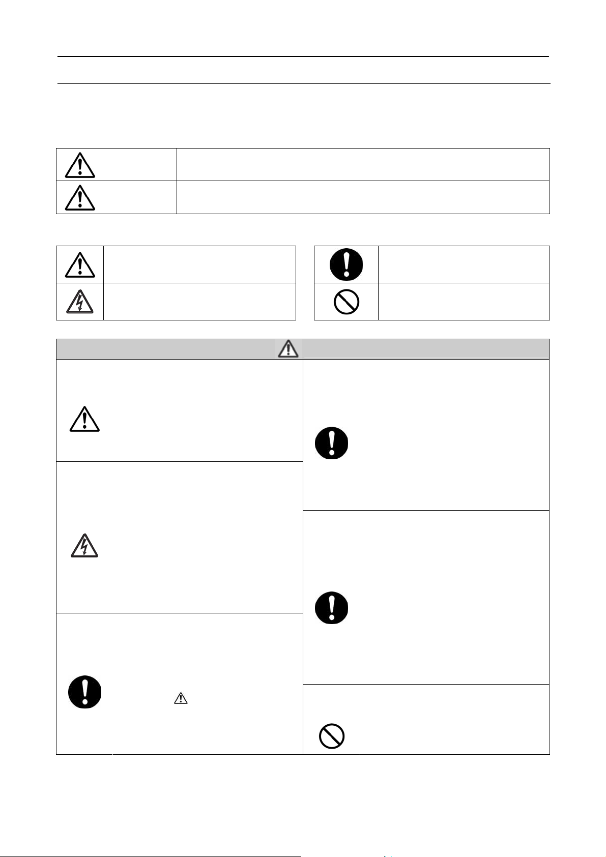
Warning
Caution
z Also note these cautionary icons
This means "CAUTION"
This means "POTENTIAL ELECTRIC
SHOCK"
This means "Potential to sustain injury or even death."
This means "Potential to sustain breakage or irreparable damage."
This means "MUST"
This means "DO NOT"
WARNING
Follow instructions. Must use same types of wires and components.
The cabinet, chassis, and labels are parts
that require attention. You must follow the
caution notes and safety instructions
presented throughout this User Manual to
prevent damage to them or injury to
yourself.
Prevent electric shock.
Exercise caution while working on the
device as the Monitor contains high
voltage parts and power supply.It is
possible to sustain severe injury or death
if you accidentally touch the wrong
parts.You must disconnect the power
supply while servicing, reassembling, or
change parts. If you touch a live
connection it is possible to sustain severe
injury or death.
Use recommended components.
Use only the recommended components
or componentst that structurally identical
to the originals. This is to ensure safety
and reliability. Pay special attention to
parts in the parts list and circuit diagrams
marked with
non-recommended components, then
electric shock or fire may result.
. If you use
Perform safety check when done.
Do not try to check the HDCP code and
combination circuit.
The Monitor uses special tubes and tapes
made from insulated materials. Moreover,
some materials are kept from making
contact with the PWB for the sake of
safety.Internal leads are kept from hot
parts or high voltage parts by means of
clamps or other measures. As such, you
must restored these parts to their original
conditions in order to prevent electric
shock or fire.
Every part (such as removed screws,
components, and wiring) must be
restored to their prior conditions after
servicing.Be sure to check everything
that was repaired for damage or
mistakes. Also measure the insulated
impedance with a meg-ohm meter to
confirm that the impedance value is more
than 4M ohm.If the impedance value is
less than 4M ohm, then electric shock or
fire may result.
Never remove the shield case protecting
the HDCP code and combination circuit.
2

PRECAUTIONS
z Cleaning the monitor's plasma screen panel
Before cleaning the monitor, turn it off and disconnect the power plug from the power outlet. To prevent
scratching or damaging of the plasma screen face, do not knock or rub the surface with sharp or hard objects.
Clean the screen with a soft cloth moistened with warm water and dry with a second soft cloth. If it is not
enough, then use a cloth with mild detergent. Do not use harsh or abrasive cleaners.
z Cleaning the monitor's cabinet
Use a soft cloth to clean the monitor's cabinet and control panel. When excessively soiled, dilute a neutral
detergent in water, wet and wring out the soft cloth in it, gently clean the cabinet, and then wipe it down with a
dry soft cloth.
Never use acid/alkaline detergents, alcoholic detergents, abrasive cleaners, powder soaps, OA cleaners, car
wax, glass cleaners, and so on. They will cause discoloration, scratches or cracks.
1. Features
z High definition Plasma display panel
The 42-inch color plasma display panel, with a resolution of 1024 (H) x 1024(V) pixels, creates a widescreen
picture. This panel features a thin form factor and can be hung on a wall with an optional wall mounting kit.
z High Performance Digital Processor
This panel displays a wide range of personal computer signals from 640 x 400 VESA, 640 x 480 VGA to 1024
x 768, 1280 x 1024 XGA.(RGB Analog input).
z Easy-to-use remote control and on-screen display system
The included remote control operates all Monitor functions. Futhermore, the on-screen display system shows
the status of the control settings in an easy-to-view fashion.
z Power saving system
When connected to a VESA DPMS-compliant PC, the monitor cuts its power consumption while idle.
3
2. Specifications
Panel
Net dimensions
Net weight
Ambient
conditions
Power supply AC100 - 240V, 50/60Hz
Power consumption/at standby <350W / <1W
Audio output Built in 10W + 10W (8 Ω) speakers
(RGB input)
Input signals
Recommended signal 25 modes
(Video input)
Input signals
Output Signal
Recommended signal 9 modes
Display
dimensions
Resolution 1024 (H) x 1024 (V) pixels
Temperatur Operating: 0°C to 40°C, Storage: -15°C to 60°C
Relative umidity Operating: 20% to 80%, Storage: 20% to 90% (non-condensing)
Input terminals
Video signals 0.7 Vp-p
Sync signals
Input terminals
Video signals
Approx. 42inches (922 (H) x 522 (V) mm, diagonal 1059mm)
1036 (W) x 773 (H) x 300 (D) mm (With stand);1036 (W) x 713 (H) x 121 (D) mm (Without stand)
41 kg (With stand);33.6 kg (Without stand)
‧ANALOG RGB input terminal (D-sub 15-pin)
‧ANALOG RGB/HDMI audio input terminal (3.5mm Stereo Mini Jack)
H/V separate, TTL level [2kΩ ]
H/V composite, TTL level [2kΩ ]
‧COMPOSITE VIDEO input terminal (RCA)
L/R COMPOSITE AUDIO input terminal (RCA)
‧S-VIDEO input teminal (RCA)
L/R S-VIDEO AUDIO input terminal (RCA)
‧Y-PB/CB PR/CR input terminal (RCA)
L/R Y-PB/CB PR/CR AUDIO input terminal (RCA)
‧HDMI input terminal (HDMI 19-pin)
Composite video: PAL, SECAM, NTSC3.58, NTSC4.43
Component - YCBCR/YPBPR video: 480i, 576i, 480p, 576p, 1080i/50, 1080i/60, 720p/50, 720p/60
S-Video: PAL, SECAM, NTSC4.43, NTSC3.58
HDMI: HDMI input signal
SUBWOOFER output terminal (RCA)‧
TV VIDEO output‧ terminal (RCA)
L/R AUDIO output terminal (RCA)‧
OPTICAL OUT DIGITAL AUDIO output terminal‧
(TV RF input)
Input signals Input terminals
z
It takes at least 30 minutes to attain the maximum picture quality.
‧ANALOG RF input terminal (NTSC)
‧DIGITAL RF input terminal (ATSC)
Applicable video signals for each input terminal
Signal Type
Terminal
ANALOG RGB
HDMI
COMPOSITE
S-VIDEO
Y-PB/CB PR/CR
Composite Video S-Video Component DVD/STB RGB
{
RCA HDMI D-sub Remarks
{
{
{
{
1080i/720p/576p/576i/480p/480i
inputs.
({: Avaliable)
4
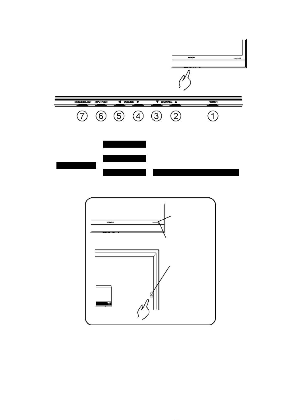
3. Component names
A
z Main unit
Control panel
z
l Adjustment buttons are located on the bottom of
the control panel
z
Indications for each button's function can be found
on the inside of the control panel cover.
1. POWER 5. VOL W
2. UP S
5. LEFT W
3. DOWN T 6. INPUT
4. VOL X
6. EXIT
4. RIGHT X 7. MENU Normal Button Action
7. SELECT Button Action when MENU engaged
Power lamp
Remote-control receiver
Main power switch
The main
power switch is
located at the
back, on the
right side.
5
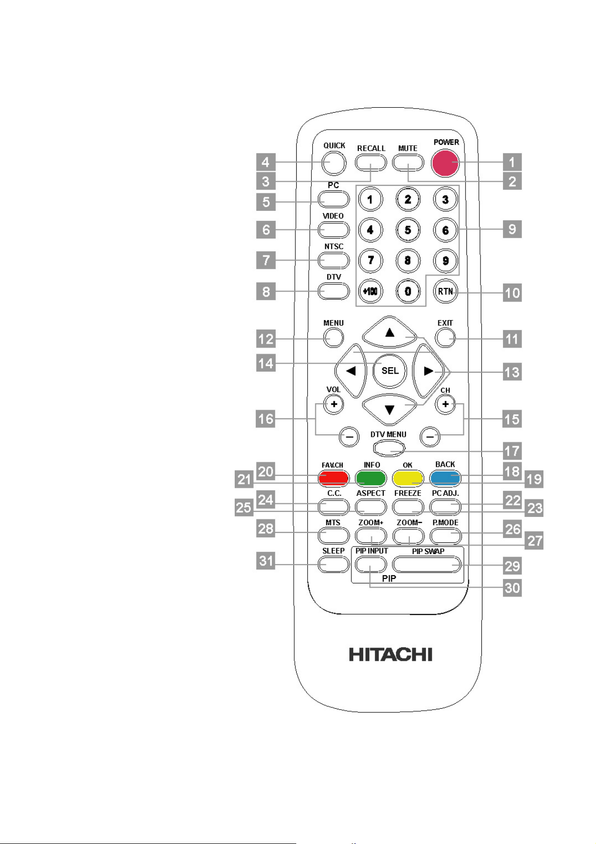
z Remote Control
1. Power Button
2. Mute Button
3. Recall Button
4. Quick Buttons
5. PC Buttons
6. Video Buttons
7. NTSC Buttons
8. DTV Button
9. Numbers Button
10. RTN Button
11. Exit Buttons
12. Menu Button
13. Up/Down/Left/Right Button
14. SEL Button
15. Ch +/- Button
16. Vol +/- Button
17. DTV Menu Button
18. Back Button
19. OK Button
20. Fav. ch. Button
21. Info Button
22. PC ADJ. Button
23. Freeze Button
24. C.C. Button
25. Aspect Button
26. P. Mode Button
27. Zoom-/+ Button
28. MTS Button
29. PIP Swap Button
30. PIP Input Button
31. Sleep Button
6
4. Service points
z Lead-free solder
This product uses lead-free solder (unleaded) to help protect the environment. Please read these instructions
before attempting any soldering work.
Caution: Always wear safety glasses to prevent fumes or molten solder from getting into
the eyes. Lead-free solder can splatter at high temperatures (600℃).
Lead-free solder indicator
Printed circuit boards using lead-free solder are engraved with an "F."
Properties of lead-free solder
The melting point of lead-free solder is 40-50℃ higher than leaded solder.
Servicing solder
Solder with an alloy composition of Sn-3.0Ag-0.5Cu or Sn-0.7Cu is recommended. Although servicing with
leaded solder is possible, there are a few precautions that have to be taken. (Not taking these precautions
may cause the solder to not harden properly, and lead to consequent malfunctions.)
Precautions when using leaded solder
z
Remove all lead-free solder from soldered joints when replacing components.
z
If leaded solder should be added to existing lead free joints, mix in the leaded solder thoroughly after the
lead-free solder has been completely melted (do not apply the soldering iron without solder).
Servicing soldering iron
A soldering iron with a temperature setting capability (temperature control function) is recommended.
The melting point of lead-free solder is higher than leaded solder. Use a soldering iron that maintains a high
stable temperature (large heat capacity), and that allows temperature adjustment according to the part being
serviced, to avoid poor servicing performance.
Recommended soldering iron:
z
Soldering iron with temperature control function (temperature range: 320-450℃)
Recommended temperature range per part:
Part Soldering iron temperature
Mounting (chips) on mounted PCB
Mounting (chips) on empty PCB
Chassis, metallic shield, etc.
320℃±30℃
380℃±30℃
420℃±30℃
The PWB assembly which has used lead free solder
(1) POWER/EMI PWB, AUDIO POW ER PWB, RS-232 PWB, AUDIO PWB, KEY PAD PWB, IR PWB, I/O PWB,
CONNECTOR PWB, SPEAKER CONNECTOR PWB, HDMI PWB
(2) MAIN PWB
(3) ATSC BOX(Digital Tuner Module) / TUNER
(4) POWER MODULE
(5) PDP MODULE (is all lead free solder. X-SUS PWB, Y-SUS PWB, LOGIC PWB, ADDRESS PWB, SDM PWB)
7
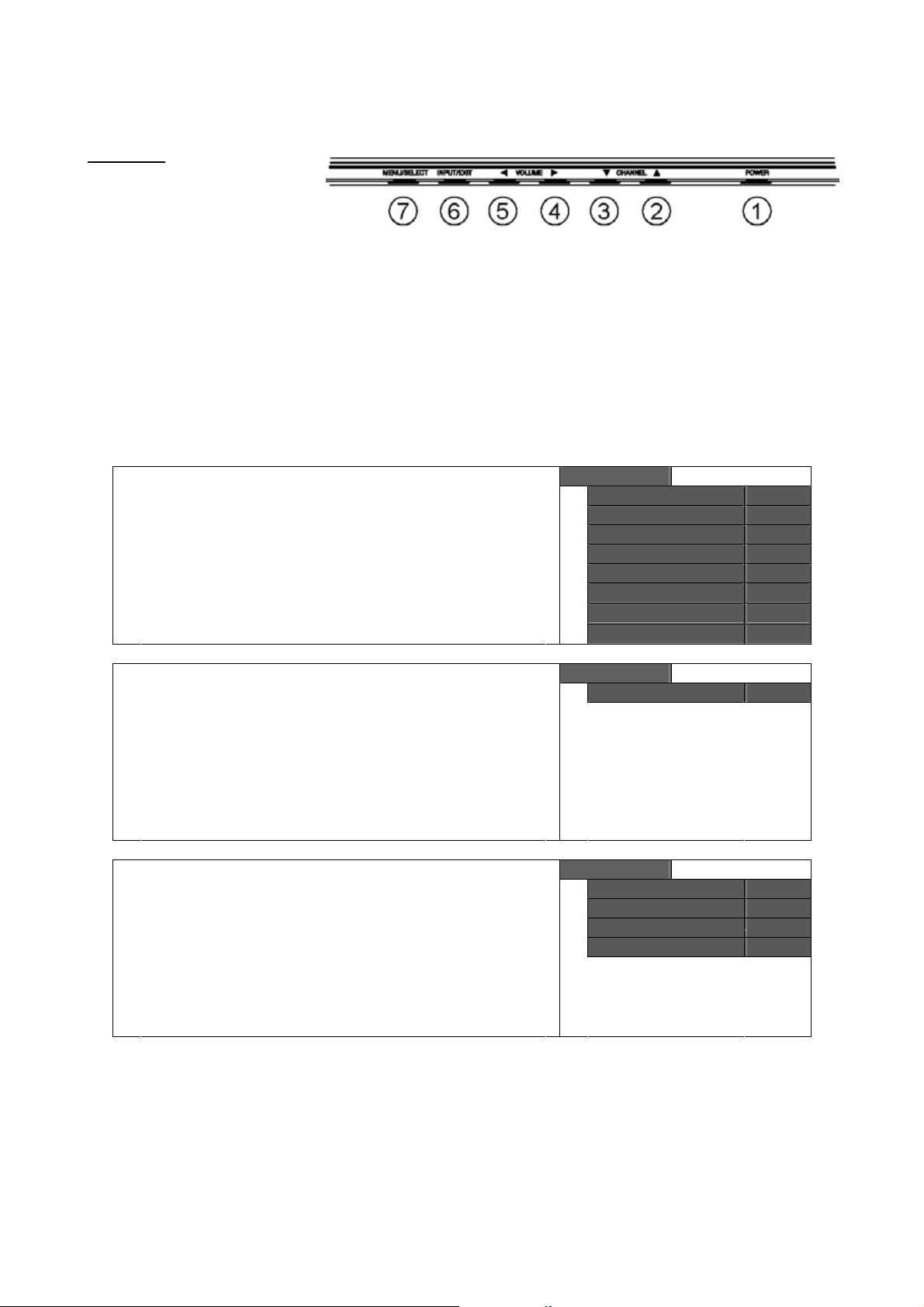
5. Adjustment & Software Update
This model has a factory mode, where the technician can access and adjust some of the color temperature
settings. The factory mode has several different appearances, depending on the input signal.
Preliminary
To access the Factory Mode, the
Plasma Monitor must be running.
z Color temperature adjustments
Follow the procedures below to make the color temperature adjustments.
Factory setting:
Cool: x=0.268 +/- 0.01, y=0.283 +/- 0.01
Warm: x=0.314 +/- 0.01, y=0.327 +/- 0.01
Netural: x=0.285 +/- 0.01, y=0.293 +/- 0.01
Black & White: x=0.335 +/- 0.01, y=0.343 +/- 0.01
Note: That a colorimetry meter (such as a Minolta CA-200) is required to measure the actual screen color
temperature.
1. Press MENU button on remote control to display the PDP
2. Select to color temperature function page under VIDEO
3.
4.
OSD menu.
item.
Press SLEEP button three times to on remote control to
display the adjustment RGB parameter.
W X to select Natural or Warm modes.
Press
Video
Picture Mode Natural
Brightness 0~100
Contrast 0~100
Color 0~100
Tint 0~100
Sharpness 0~31
Color Temperature Cool
Reset
Video
Color Temperature Cool
Video
Color Temperature Cool
Red . 0~255
Green
Blue . 0~255
. 0~255
8

Page intentionally left blank

Page intentionally left blank

Page intentionally left blank

Page intentionally left blank
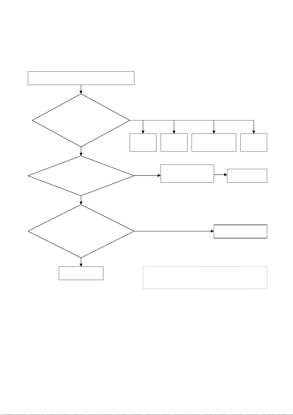
6. Troubleshooting
Note: Voltage shown for CN10 and CN11 are at Power On State.
Power off voltages are 0V, except CN11 Pin 10, this voltage is
always present.
CH 1
The flow chart shown below will help you to troubleshoot your Monitor set with it doesn’t display normally.
Each procedure offers a simple way to check for system errors. Before starting, ensure that there is a signal in
and that the Monitor is turned on.
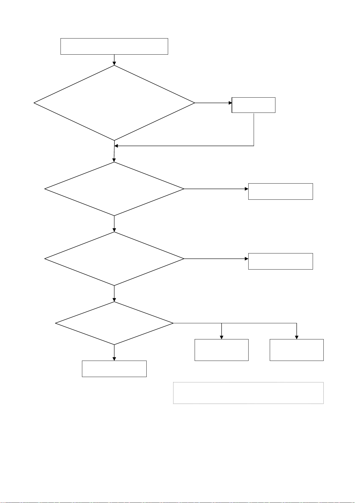
z Power turn on issue
Power cannot be turn on (LED does not light)
Is the input voltage
applied to Power
supply unit?
(CN61 ①③)
No
AC inlet
Yes
Check if the Power Cord
has been well connected
to TV?
Yes
Are the voltages applied
to CN10①⑤⑥ pins and
CN11①③④⑩ pins of
Power supply unit?
Yes
PBC-Main
Power
switch
No
(CN61) 110V ①L ③W
(CN10) ①+5V ⑤+12V ⑥+12V
(CN11) ①+5V ③+3.3V ④+3.3V ⑩+5V
Connect the wire
properly.
No
AC Fuse 5HTP10
TL.510A 250V
Power supply unit
Test again
13
Filter
PWB
z No sound issue
Picture is diaplayed. But no sound
Take off the back cover and
check ifl wires of
terminals have been well
connected to the
and
the speakers
PCB-Main
speakers
No
Check
?
No sound
Yes
Are the voltages applied to
CN2
①②
of the power
supply unit?
No
Power supply unit
Yes
Are the signals applied to
P23
①②③④
PBC-Main?
of the
No
PCB-Main or PCB-I/O
Yes
Are there signals on
the speaker terminals?
No
Yes
Speakers
PCB-Audio
PCB-Speaker
Connector
(CN2)
(P23) ①NC ②L ③GND ④R
①+15.5~16V ②GND
14
 Loading...