

Page 1
ENGLISH
USER’S MANUAL
Thank you very much for purchasing the HITACHI LCD
Monitor. Before using your monitor, please carefully read the
"SAFETY INSTRUCTIONS" and this "USER'S MANUAL" so
you will know how to operate the monitor properly. Keep this
manual in a safe place. You will find it useful in the future.
32LD7200
Notes on lnstallation Work:
This product is marketed assuming that it is installed by qualified
personnel with enough skill and competence. Always have an
installation specialist or your dealer install and set up the product.
HITACHI cannot assume liabilities for damage caused by mistake
in installation or mounting, misuse, modification or a natural
disaster.
Note for Dealers:
After installation, be sure to deliver this manual to the customer
and explain to the customer how to handle the product.
Page 2

Important
Please read this User's Manual thoroughly, especially the Safety
Instructions on Page 3 to 6. Mis-use may cause damage to your
LCD monitor, which could shorten its lifespan, or cause injury to
yourself. Should you encounter any difficulty in the set-up or
operation of your monitor, firstly refer to the Troubleshooting
guide at the rear of this manual.
In the unlikely event of a problem occurring with your LCD
monitor, switch off at the mains sockets, pull out the plugs, and
contact your dealer immediately.
CAUTION
Under no circumstances remove the rear cover of your LCD
monitor.
Never guess or take any chances with electrical equipment of
any kind - it is better to be safe than sorry!
Software Notice
It is prohibited for the end user of this product to copy, reverse
engineer or reverse compile the software included therein, save
to the extent permitted by law.
LCD Monitor
After the LCD monitor has been on for any length of time, you
will notice that the screen becomes warm. Please note that this
is normal.
Sometimes the screen might have some tiny bright or dark spots.
Please note that this is normal.
CAUTION
To prevent scratches or damages to the LCD screen, do not
knock or rub the surface with sharp or hard objects. Clean the
screen with a soft cloth moistened with warm water and dry with
a soft cloth. A mild soap may be used if the screen is extremely
dirty. Do not use harsh or abrasive cleaners!
CAUTION
Use a soft cloth to clean the cabinet and control panel of the
monitor. When excessively soiled dilute a neutral detergent in
water, wet and wring out the soft cloth and afterward wipe with a
dry soft cloth.
Never use acid/alkaline detergent, alcoholic detergent, abrasive
cleaner, powder soap, OA cleaner, car wax, glass cleaner, etc.
especially because they would cause discoloration, scratches or
cracks.
FEATURES
FEATURES
Large-screen, high-definition LCD panel
The 32-inch colour LCD panel with a resolution of 1366(H) X
768(V) pixels, creates a high-definition, large-screen (aspect
ratio:16:9) and low-profile flat display. Free from electromagnetic
interferences from geomagnetic sources and ambient power
lines, the panel produces high-quality display images free from
colour misconvergence and display distortion.
High Performance Digital Processor
A wide range of input signals can be handed, including
composite, component, and HDMI.
High Definition Digital Processor creates the fine-textured image
with dynamic contrast.
In addition, it corresponds to a broad array of personal computer
signals, from 640 x 400 and 640 x 480 VGA to 1600 x 1200
UXGA. (Analogue Input)
Easy-to-use remote control and on screen display
system
The remote control included eases the work of setting display
controls. Further, the on-screen display system, displays the
status of signal reception and display control settings in an
easyto-view fashion.
Connecting to an Audio Visual Device
• Three Scart terminals
terminal
video output terminal is also provided as a monitoring output.
*1
*2
*3
• A wide range of devices can be also connected besides personal
computers.
*3
, and a HDMI termainal have been added. A composite
AV1 scart applies to composite/ S-Video.
AV2 and AV3 apply to composite/ RGB.
A composite/ S terminal = Side Input.
With AV4 input, if a composite terminal and a component
terminal are used at the same time, the component terminal
would govern.
Power Swivel Feature
It allows to turn the LCD monitor left or right within ± 30 degree
using the remote control.
*1
, composite/S terminal*2, a component
ENGLISH
1
Page 3

CONTENTS
FEATURES ............................................................1
SAFETY INSTRUCTIONS ......................................3
NOTES...................................................................7
COMPONENT NAMES............................................8
Main Unit .................................................................................8
Remote control ........................................................................9
Loading Batteries ................................................................9
Handling the Remote Control .............................................. 9
INSTALLATION INSTRUCTIONS .........................12
Installation .............................................................................12
Anti-tumble measures............................................................ 12
Connection to an Audio Visual Device...................................13
Connecting to a PC................................................................ 15
Connecting the Speaker Cables ............................................16
Mounting the Side Input......................................................... 17
Power Cord Connection......................................................... 18
OPERATING INSTRUCTIONS ..............................19
Turning Power On and Off..................................................... 19
Input Switching ......................................................................20
Size Switching .......................................................................20
Volume Adjustment................................................................ 22
Audio Mute ............................................................................22
Power Swivel .........................................................................23
Input Signal Screen Display................................................... 24
Displaying MULTI PICTURE .................................................. 25
Picture Freezing.....................................................................27
Using the Menu Screen (On-screen display system).............28
SETUP MENU (TV mode) .....................................................29
SETUP MENU (Video mode)................................................. 31
SETUP MENU
(RGB mode: RGB1 (DVI-PC), RGB2 (RGB)) ........................32
FUNCTION MENU................................................................. 34
PICTURE MENU (TV/Video mode) .......................................35
PICTURE MENU (RGB mode) ..............................................38
AUDIO MENU........................................................................ 39
TIMER MENU........................................................................ 40
LANGUAGE MENU ...............................................................40
OTHER FEATURES..............................................41
Automatic Store..................................................................... 41
Audio Switching..................................................................... 42
Power Save Mode................................................................. 43
DVD Player/ STB Selection................................................... 43
Signal Check (RGB mode) .................................................... 44
TROUBLESHOOTING ..........................................45
Symptoms That Seemingly Appear to be Failures................. 45
Actions to Correct Abnormal Displays ................................... 47
PRODUCT SPECIFICATIONS...............................48
Signal Input ........................................................................... 49
Recommended Signal List .................................................... 50
Note about This Manual
• The information in this manual is subject to change without notice.
• Whilst meticulous care has been taken in the preparation of this manual, you are requested to notify your dealer or us should you have
any comments, views or questions about our product.
• Fully understand the prerequisites to using the product, such as hardware and software specifications and constraints, in using the
product. We are not held liable for damages caused by improper handling of the product.
• Reproduction of this manual in whole or in part without our prior written permission is prohibited.
• The product names mentioned in this manual may be trademarks or registered trademarks of their respective owners.
2
Page 4
SAFETY INSTRUCTIONS
SAFETY INSTRUCTIONS
This LCD monitor has been designed and manufactured to meet international safety standards, but like any electrical equipment, care
must be taken if you are to obtain the best results and safety is to be assured.
Before using this product, please read and understand the Safety Instructions thoroughly to ensure correct usage, and follow all the
instructions.
About the Symbols
Various symbols are used in this manual, the user’s manual and on the product itself to ensure correct usage, to prevent danger to
the user and others, and to prevent property damage. The meanings of these symbols are described below. It is important that you
read these descriptions thoroughly and fully understand the contents.
WARNING
CAUTION
This symbol indicates information that, if ignored, could possibly result in personal injury or even death due to
incorrect handling.
This symbol indicates information that, if ignored, could result possibly in personal injury or physical damage due to
incorrect handling.
Typical Symbols
This symbol indicates an additional warning (including cautions). An illustration is provided to clarify the contents.
This symbol indicates a prohibited action. The contents will be clearly indicated in an illustration or nearby (the symbol to the
left indicates that disassembly is prohibited).
This symbol indicates a compulsory action. The contents will be clearly indicated in an illustration or nearby (the symbol to
the left indicates that the power plug should be disconnected from the power outlet).
WARNING
Never use the monitor if a problem should occur.
Abnormal operations such as smoke, strange odor, no image, no sound, excessive sound, damaged casing, elements,
cables, penetration of liquids or foreign matter, etc. can cause a fire or electrical shock.
In such case, immediately turn off the power switch and then disconnect the power plug from the power outlet. After
making sure that the smoke or odor has stopped, contact your dealer. Never attempt to make repairs yourself because this
could be dangerous.
Do not insert liquids or foreign objects.
Penetration of liquids or foreign objects could result in fire or electrical shock. Use special caution in households where
children are present.
If liquids or foreign objects should enter the monitor, immediately turn off the power switch, disconnect the power plug from
the power outlet and contact your dealer.
• Do not place the monitor in a bathroom.
• Do not expose the monitor to rain or moisture.
• Do not place flower vases, pots, cups, cosmetics, liquids such as water, etc. on or around the monitor.
• Do not place metals, combustibles, etc on or around the monitor.
Never disassemble or modify the monitor.
The monitor contains high voltage components. Modification could result in fire or electrical shock.
• Never remove any fixed cover.
Do not give the monitor any shock or impact.
If the monitor should be shocked and/or broken, it could result in an injury, and continued use could result in fire or
electrical shock. If the glass panel is broken or damaged, immediately turn off the power switch, disconnect the power plug
from the power outlet and contact your dealer.
Do not place the monitor on an unstable surface.
If the monitor should be dropped and/or broken, it could result in an injury, and continued use could result in fire or
electrical shock.
• Do not place the monitor on an unstable, slant or vibrant surface such as a wobbly or inclined stand.
Do not obstruct the ventilation of the monitor.
If the ventilation is obstructed during the operation of the monitor or just after switching off the power, it could result in
damage and shorten the lifespan of your monitor due to overheating. Make sure there is ample ventilation.
• Keep a space of 100mm (10cm) or more between the sides, rear and top of the monitor and other objects such as walls.
• Do not place anything around ventilation openings of the monitor.
• Never block ventilation openings.
• Do not put the LCD screen side up.
• Do not cover the monitor with a tablecloth, etc.
• Do not place the monitor on a carpet or bedding, or near a curtain.
Use only the correct power outlet.
Incorrect power supply could result in fire or electrical shock. Use only the correct power outlet depending on the indication
on the monitor and the safety standard.
• The enclosed power cord must be used depending on the power outlet to be used.
Disconnect the
plug from the
power outlet.
Do not
disassemble.
ENGLISH
3
Page 5
SAFETY INSTRUCTIONS (continued)
About the Symbols (continued)
WARNING
Be cautious of the power cord connection.
Incorrect connection of the power cord could result in fire or electrical shock.
• Do not touch the power cord with a wet hand.
• Check that the connecting portion of the power cord is clean (with no dust), before using. Use a soft and dry cloth to clean the power
plug.
• Insert the power plug into a power outlet firmly. Avoid using a loose, unsound outlet or contact failure.
• Do not cut off the fitted power plug, the removal of which could lead to impaired performance. If you wish to extend the lead, obtain an
appropriate extension lead or consult your dealer.
• Should you require replacing the fuse in the molded plug with a new fuse, then please replace with new one of the same value, type
and approval as the original. Ensure the fuse cover is returned to its original position.
Be sure to keep safety ground connection.
Connect the ground terminal of AC inlet of this monitor with the ground terminal provided at the power outlet using the enclosed power
cord. If the provided plug does not fit your outlet, consult an electrician for replacement of the obsolete outlet.
Be careful in handling the power cord and external connection cables.
If you keep using a damaged power cord or cables, it can cause a fire or electrical shock. Do not apply too much heat, pressure or tension to the power
cord and cables.
If the power cord or cables are damaged (exposed or broken core wires, etc.), contact your dealer.
• Do not place the monitor or heavy objects on the power cord and cables. Also, do not place a spread, cover, etc, over them because
this could result in the inadvertent placing of heavy objects on the concealed power cord or cables.
• Do not pull the power cord and cables. When connecting and disconnecting the power cord or cables, do it with your hand holding the
plug or connector.
• Do not place the cord near the heater.
• Do not touch the power plug just after disconnecting it from the power outlet to prevent electric shock.
• Do not touch the power plug when lightening is close to you.
• Avoid coiling the power cord and bending it sharply.
• Protect the power cord from being walked on, pinched particularly at plugs, conveniences receptacles, and the point where they exit
from the apparatus.
• Do not modify the power cord.
Be careful in handling the battery of the remote control.
Incorrect handling of the battery could result in fire or personal injury. The battery may explode if not handled properly.
• Keep the battery away from children and pets. If swallowed consult a physician immediately for emergency treatment.
• Do not allow the battery to be exposed to fire or water.
• Avoid fire or high-temperature environment.
• Do not hold the battery with metallic tweezers.
• Keep the battery in a dark, cool and dry place.
• Do not short circuit the battery.
• Do not recharge, disassemble or solder the battery.
• Do not physically impact the battery.
• Use only the battery specified in the manual of this monitor.
• Make sure the plus and minus terminals are correctly aligned when loading the battery.
• If you observe a leakage of the battery, wipe out the liquid and then replace the battery. If the liquid adheres your body or clothes, rinse
well with water.
• Obey the local laws on disposing the battery.
• FOR THE CUSTOMERS IN THE U.K.
THIS PRODUCT IS SUPPLIED WITH A TWO PIN MAINS PLUG FOR USE IN MAINLAND EUROPE. FOR THE U.K. PLEASE REFER TO THE
NOTES ON THIS PAGE.
IMPORTANT FOR UNITED KINGDOM
WORDING FOR CLASS I EQUIPMENT INSTRUCTION BOOKS AND LABELS
The mains lead on this equipment is supplied with a molded plug incorporating a fuse, the value of which is indicated on the pin face of the plug.
Should the fuse need to be replaced, an ASTA or BSI approved BS 1362 fuse must be used of the same rating. If the fuse cover is detachable never
use the plug with the cover omitted. If a replacement fuse cover is required, ensure it is of the same colour as that visible on the pin face of the plug.
Fuse covers are available from your dealer.
DO NOT cut off the mains plug from this equipment. If the plug fitted is not suitable for the power points in your home or the cable is too short to reach
a power point, then obtain an appropriate safety approved extension lead or consult your dealer.
Should it be necessary to change the mains plugs, this must be carried out by a competent person, preferably a qualified electrician.
If there is no alternative to cutting off the mains plug, ensure that you dispose of it immediately, having first removed the fuse, to avoid a possible
shock hazard by inadvertent connection to the mains supply.
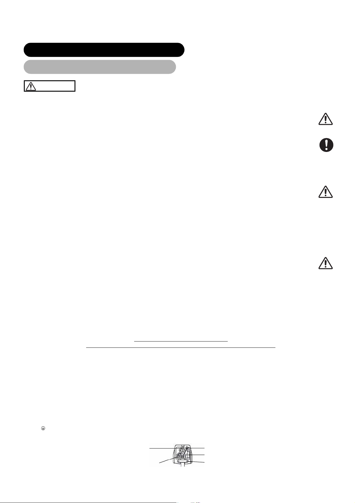
WARNING: THIS EQUIPMENT MUST BE EARTHED
IMPORTANT
The wires in the mains lead are coloured in accordance with the following code :
Green and Yellow = Earth, Blue = Neutral, Brown = Live.
As these colours may not correspond with the coloured markings identifying the terminals in your plug, proceed as follows:
The wire which is coloured GREEN and YELLOW must be connected to the terminal in the plug which is marked with the letter E or by the earth
symbol
The wire coloured BLUE must be connected to the terminal marked with the letter N or coloured BLUE or BLACK. The wire coloured BROWN must be
or coloured GREEN or GREEN and YELLOW.
connected to the terminal marked with the letter L or coloured BROWN or RED.
Green & Yellow
to Earth
Blue to Neutral
Surely connect
the ground wire.
Brown to Live
Fuse
Cord Clamp
4
Page 6
SAFETY INSTRUCTIONS (continued)
About the Symbols (continued)
CAUTION
Be careful in moving the monitor.
Neglect could result in an injury or damage.
• Do not move the monitor during use. Before moving, disconnect the power plug and all external connections.
• You are advised to move the monitor with two persons.
• Avoid any impact or shock to the monitor; particularly take care of glass screen.
Do not put anything on top of the monitor.
Placing anything on the monitor could result in loss of balance or falling, and cause an injury or damage. Use special
caution in households where children are present.
Avoid a humid or dusty place.
Placing the monitor in a smoke, a highly humid, dusty place, oily soot or corrosive gas could result in fire or electrical
shock.
• Do not place near the kitchen, a humidifier or other place where there is oil, smoke or humidity.
Avoid a high temperature environment.
The heat could have adverse influence on the monitor and other parts, and could result in transformation, melting or fire.
• Do not place the monitor, the remote control and other parts in direct sunlight or near a hot object such as heater, etc.
• Do not put the monitor in a place where the temperature is widely changing.
Remove the power cord for complete separation.
• For safety purposes, disconnect the power cord if the monitor is not to be used for prolonged periods of time.
• Before cleaning, turn off and unplug the monitor. Neglect could result in fire or electrical shock.
Be careful in operating power swivel.
• Placing hands or faces near the monitor whilst operating the swivel function could cause a physical injury or damage.
• Use special caution in households where children are present.
PRECAUTIONS
Installation environment
Do not obstruct a ventilation hole.
Do not put the monitor on carpet or blanket, or near a curtain which has a possibility of obstructing a ventilation hole of the monitor.
Do not put the monitor in the following places.
• Hot places such as near heater, place exposed to the direct rays of the sun.
• A place where the temperature is widely changing.
• Places with soot, dust or high humidity.
• Poor air ventilation place.
• Place near fire.
• A wet place such as bathroom, or shower room.
• Place where you can trip over it.
• Always vibrating or strongly vibrating places.
• Distorted or unstable places.
Please avoid installing the monitor directly on the wooden floor. Depending on the quality and the condition of the floor, the monitor
stand may stick to the floor face, and the surface could come off when the monitor is lifted up.
How to view the monitor
If you use the monitor in too dark a room, your eyes may become tired.
Please use it in a reasonably bright room.
Avoid direct rays of the sun to the screen in order to prevent eye fatigue.
Your eyes will get fatigued after viewing the monitor for long period of time.
Relax your eyes by viewing away from the monitor from time to time.
Please watch the monitor in downward direction.
How to clean the LCD screen panel of the monitor
Before cleaning the monitor, turn off the monitor and disconnect the power plug from the power outlet.
To prevent scratching or damaging the LCD screen face, do not knock or rub the surface with sharp or hard objects. Clean the screen with
a soft cloth moistened with warm water and dry with a soft cloth. If it is not enough, then use a cloth with mild detergent. Do not use harsh or
abrasive cleaners.
How to clean the cabinet of the monitor
Use a soft cloth to clean the cabinet and control panel of the monitor. When excessively soiled dilute a neutral detergent in water, wet and
wring out the soft cloth and afterward wipe with a dry soft cloth.
Never use acid/alkaline detergent, alcoholic detergent, abrasive cleaner, powder soap, OA cleaner, car wax, glass cleaner, etc. especially
because they would cause discoloration, scratches or cracks.
Disconnect the
plug from the
power outlet.
ENGLISH
5
Page 7

SAFETY INSTRUCTIONS (continued)
About the Symbols (continued)
Prevention of an obstacle to Radio receivers
This monitor has been designed pursuant to the international EMI standards. This is to prevent a problem to Radio receivers.
• Keep the monitor away from Radio.
• Adjust Radio antennas in order for the monitor not to receive interference.
• The antenna cable of Radio should be kept away from the monitor.
• Use a coaxial cable for antenna.
You can check if this monitor influences Radio receivers by turning off all other equipment other than the monitor.
If you find a problem receiving Radio when using the monitor, check the instructions mentioned above.
Precautions for the cable connection
• Do ensure that all connections, (including the power plug, extension leads and interconnections between the pieces of equipment), are
properly made and in accordance with the manufacturers instructions. Switch off and withdraw the power plug before making or changing
connections.
• Confirm the connector is fixed tightly when the signal cable is connected.
• Also confirm the screws on the connector are tightened.
• Plug the power cord of the monitor into a different socket from that for other equipment, such as Radio etc..
• Use a plug with ground terminal and make sure that it connects to the ground.
Precaution during transportation
Please pay attention when you transport this monitor because it is heavy.
Furthermore, use the original carton box and its packaging materials when the monitor is transported.
Failure to transport the monitor in any carton except the original carton may result in damage to the monitor.
Save the original carton box and all packing material.
Do not push the monitor over sideways as transporting it. It may cause damage on the panel glass, increase of the screen defects and/or
damage of the internal fluorescent lamps.
Do not physically impact the remote control.
A physical impact could cause damage or malfunction of the remote control.
• Take care not to drop the remote control.
• Do not place heavy objects on the remote control.
Avoid strong rays.
Any strong rays (such as direct sun rays or room lighting) onto the remote control sensors could invalidate the remote control.
Avoid radio interference.
Any interfering radiation could cause distorted images or noises.
• Avoid radio generator such as a mobile telephone, transceiver, etc. around the monitor.
Set the sound volume at a suitable level.
It is better to keep the volume level low and close the windows at night to protect the neighbourhood environment.
Precautions for the installation
• Do not use makeshift stands and NEVER fix legs with wood screws - to ensure complete safety, always fit the manufacturers approved
stand or legs with the fixings provided according to the instructions.
• Use only with the cart, stand, tripod, bracket, or table specified by the manufacturer, or sold with the apparatus. When a cart is used, use
caution when moving the cart/apparatus combination to avoid injury from tip-over.
• This product is designed to comply with the recommended safety standards for tilt and stability. Do not apply excessive pulling force to the
front, or top, of the cabinet that could cause the product to overturn resulting in product damage and/or personal injury.
• Follow instructions for wall, shelf or ceiling mounting as recommended by the manufacturer.
• Only use the attachments/accessories specified by the manufacturer.
• Consult your dealer if you are in any doubt about installation, operation or safety of your equipment.
Other precautions
• Do not leave equipment switched on when it is unattended unless it is specifically stated that it is designed for unattended operation or has
a stand-by mode. Switch off using the switch on the equipment and show your family how to do this. Make special arrangements for infirm
or handicapped people.
• Disposal of this product may require specific instructions pertaining to your resident region.
• Never guess or take any chances with electrical equipment of any kind - it is better to be safe than sorry!
6
Page 8

NOTES
NOTES
About screen defects
• High precision technology is used in the making of LCD panels, but there may be dark spots (points that do not illuminate) and bright spots
(points that are too bright) in some cases. These do not indicate a malfunction.
About residual images
• In some cases, residual images may remain after the short-term display of still images is displayed. These will disappear in a few minutes,
and the display will return to normal. However, if used in high temperatures, it sometimes spends some tens of minutes to return to normal.
Please note that this is not a malfunction.
About the panel screen
• LCD screen display images by illuminating fluorescent lamps inside of the panel. Because of this, the temperature of the panel surface may
rise in some cases. Also, LCD panels are made of finely processed glass, so please avoid pushing by fingers or hands and giving strong
impact on the panel. It may cause damage to the LC cells, and/or there is danger of glass breakage.
About the power swivel
• Do not put hands or faces close to the monitor whilst operating the swivel function.
• It could cause a physical injury. Use special caution in households where children are present. (Refer to Power Swivel shown on
Using in low temperatures
• The response speed of LCD panel becomes slow as the ambient temperature goes down. This feature may cause residual images in some
cases, but this is not a malfunction. It will return to normal in a while after the temperature becomes normal.
)
23
ENGLISH
7
Page 9
COMPONENT NAMES
COMPONENT NAMES
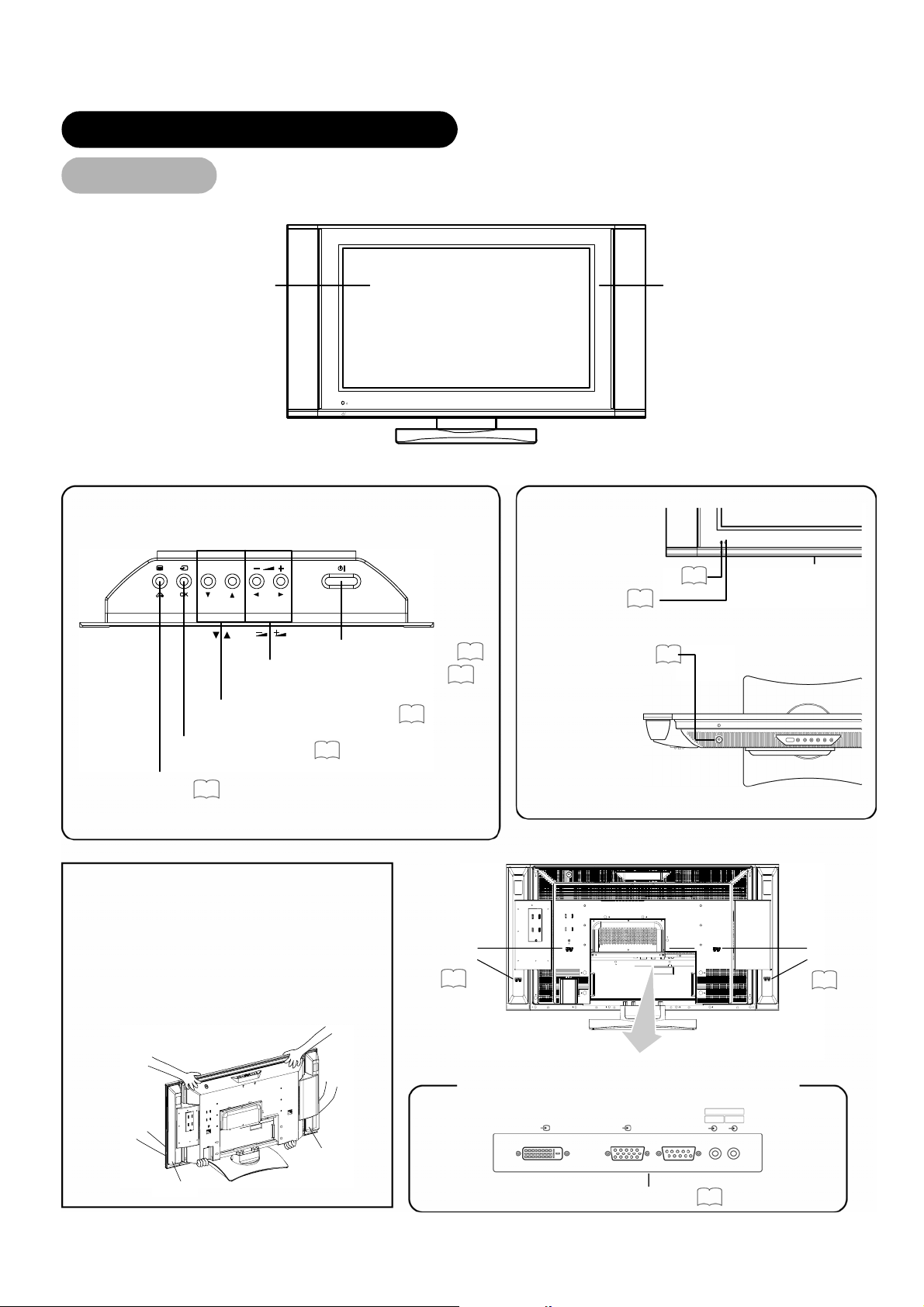
Main Unit
Main Unit
• Adjustment buttons are located
on the top.
Panel
Control panel
Front
Remote-control receiver
Indicating lamp
19
Cabinet
(front frame)
9
SUB-POWER button
VOLUME UP/DOWN buttons
19
22
(WXADJUST buttons)
CHANNEL UP/DOWN buttons
20
(STSELECT buttons)
INPUT SELECT button
20
(OK button)
MENU button
• ( ) indicates the function whilst the MENU is displayed on the screen.
28
Caution when moving the main unit
• As this product is heavy, whenever it is moved, two
people are required to transport it safely.
• Whenever the unit is moved it should be gripped by
holding the top of the monitor, and the unit should
then be held at the base on both sides for stability
as shown.
• Do not hold the speaker units whilst moving the set.
Speaker
terminals
16
The speaker holders may be separated off and the
monitor may fall, and it may result in a physical
injury.
• The main power switch is located on the top.
Main power switch
19
Front
Rear
Rear
Speaker
terminals
16
8
Speaker
Speaker
External device connection terminals
DIGITAL INPUT
RGB 1
ANALOG INPUT
RGB 2
PC PC
AUDIO IN
RGB 1 RGB 2
RGB input terminals
15
Page 10
W
COMPONENT NAMES (continued)
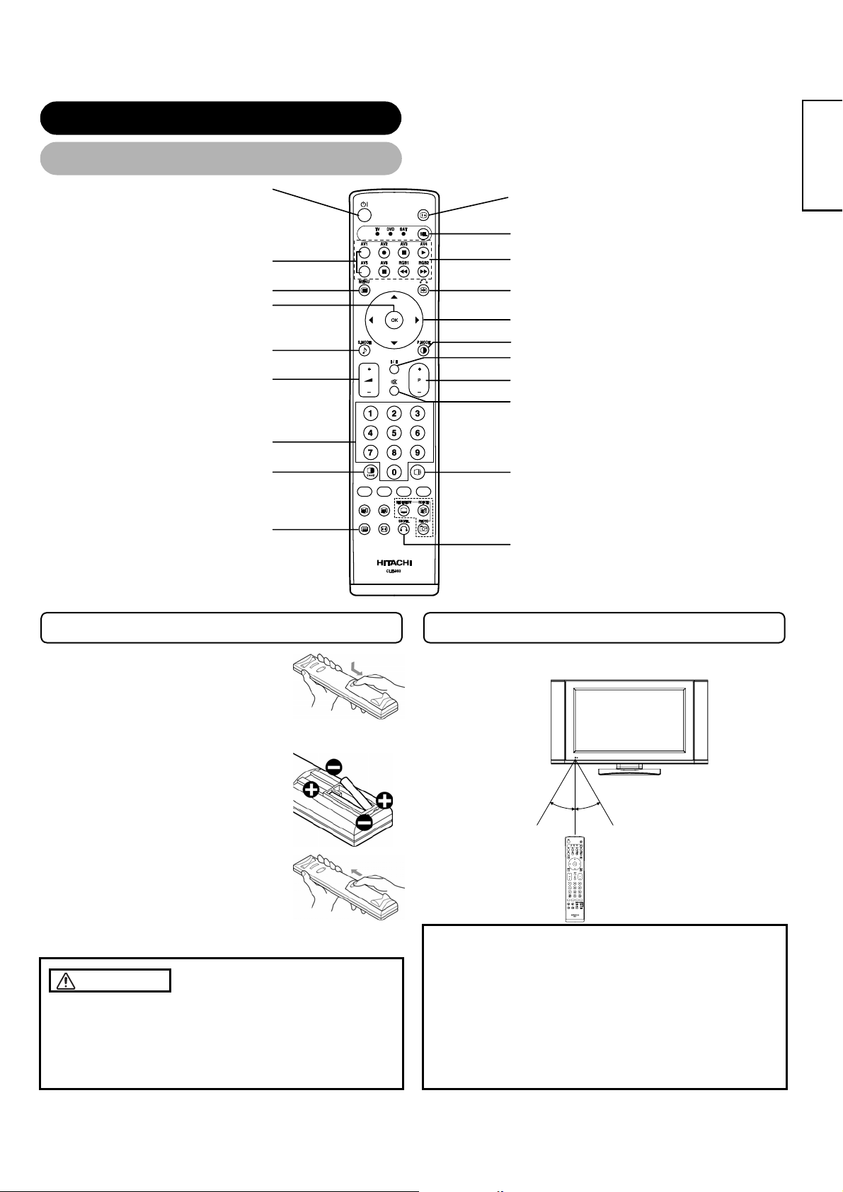
Remote control
Remote control
POWER button
INPUT SELECT buttons
MENU button
OK button
SOUND MODE button
VOLUME UP/DOWN button
ROGRAM SELECT buttons
MULTI MODE button
TV/TEXT button
(TV)
(TV)
ENGLISH
RECALL button
FUNCTION SELECT button
DVD CONTROL buttons
FREEZE/RETURN button
SELECT/ADJUST button
PICTURE MODE button
CH I/CH II button (TV)
CHANNEL UP/DOWN button (TV)
MUTE button
MULTI PICTURE button
SWIVEL button
Loading Batteries
Loading Batteries
1. Open the battery cover.
• Slide back and remove the battery cover
in the direction of the arrow.
2. Load batteries.
• Load two Size AA batteries included
observing the correct polarities.
3. Close the battery cover.
• Replace the battery cover in the direction
of the arrow and snap it back into place.
CAUTION
• Do not use new and old batteries together. The batteries could
explode or leak, resulting in fires, physical injury, or stains.
• When loading batteries, observe their correct polarities as
marked on the product. If loaded in the wrong direction, the
batteries could explode or leak, resulting in fires, physical injury,
or stains.
Handling the Remote Control
Handling the Remote Con trol
Use the remote control within about 5 m from front of the unit's
remote-control sensor and within 30 degrees on both sides.
ithin 30 degrees Within 30 degrees
About 3m About 3m
About 5m
ATTENTION
• Do not drop or impact the remote control.
• Do not splash the remote control with water or put it on a wet
object to avoid possible failures.
• Before leaving the remote control out of use for an extended
period of time, remove the batteries from it.
• If the remote control begins to lack responsiveness, replace the
batteries.
• Strong light such as direct sunlight impinging on the
photoreceptor of the remote control can cause operational
failure. Position this unit to avoid direct contact with such light.
9
Page 11
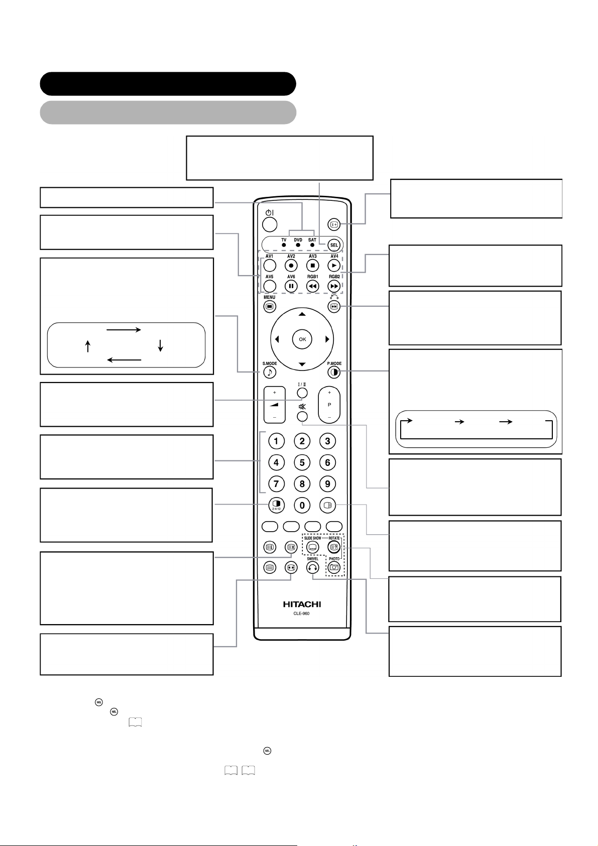
COMPONENT NAMES (continued)
Remote control (continued)
FUNCTION SELECT
Press this button to indicate function
mode with a lamp. *1
DVD and SAT
INPUT SELECT
Press these buttons to change input
mode.
SOUND MODE
You may recall the sound mode by
pressing this button. Each time pressed,
sound mode is changed in following
sequence.
Movie Music
SpeechFavourite
CH I/II
This button is for A2 / NICAM models
only.
*2
RECALL (TV / VIDEO / RGB)
Press this button to display input signal.
DVD CONTROL
You can use these buttons to operate
the selected brand of DVD player.
FREEZE/RETURN
Press this button to change the picture
to freeze mode. Press it again to return
to normal picture.
PICTURE MODE
You may recall the picture mode by
pressing this button. Each time pressed,
picture mode is changed in following
sequence.
Dynamic Natural Cinema
PROGRAM SELECT
Press these buttons to select a TV
program directly.
MUTE
Press this button to turn off the set
sound. When press again or the
MULTI MODE
In multi-picture mode, pressing this
volume up button, the audio will be
restored.
button will change the multi-picture
mode.
MULTI PICTURE
Press this button to change the screen
to multi-pictures. Press it again to return
TIME (TV)
to normal picture.
Pressing this button can indicate the
time by On-Screen display when
receiving a TV program on the screen
including TELETEXT service with the
time information.
PHOTO INPUT
These buttons are not available in this
model.
SWIVEL
ZOOM
Press this button can change Picture
size.
Press this button to rotate TV. Use
cursor key (WX) to select the degree of
rotation.
*1 FUNCTION SELECT button
This remote control has functions to control other makers of DVD player, DVD Recorder, and Set Top Box as well as this set.
Press the
Each time the
For details, refer to
button to switch between TV, DVD and SAT modes.
button is pressed, the indicator will light below the function selected.
43
.
*2 LED
The LED indicator lamps for DVD and SAT have 2 modes (Lit or blinking).
Lit: Indicates the mode that has been selected. Press the
Blinking: Indicates that the maker of DVD or STB can be set. You can set up the maker of DVD or STB whilst the LED is still
blinking (30 sec). For details, refer to
43 44
button to change modes when the LED is lit.
.
10
Page 12
)
T
COMPONENT NAMES (continued)
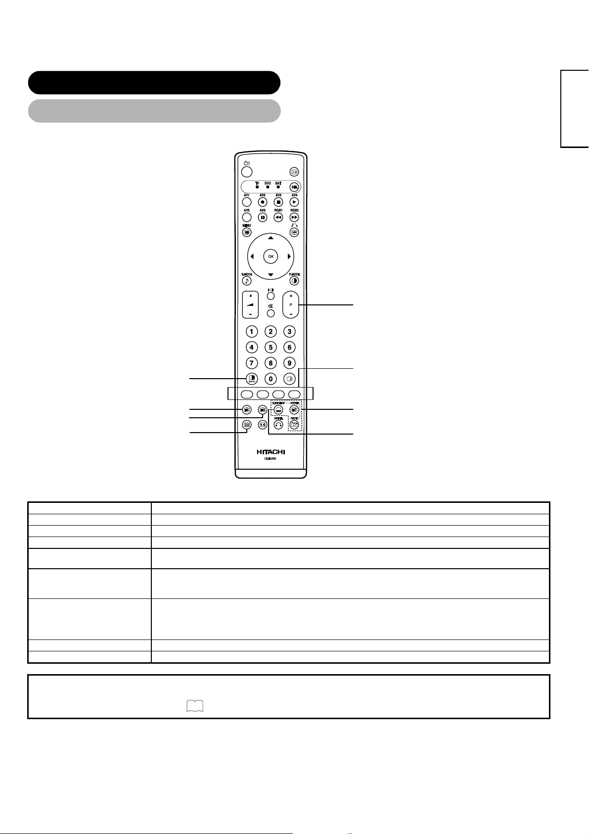
Remote control (continued)
[Buttons for TELETEXT Mode]
EXT / TV+TEXT button
ENGLISH
PAGE UP / DOWN button
COLOUR buttons
(RED, GREEN, YELLOW, BLUE
INDEX button
CANCEL button
TV / TEXT button
REVEAL button
SUB TITLE button
TELETEXT FUNCTION
Buttons on Remote Control
TV / TEXT
TEXT / TV + TEXT
INDEX
SUB TITLE
CANCEL
This switches the receiver between the TV mode and the TELETEXT mode.
In TELETEXT mode, this button switches between TV+TEXT screen (split) and TELETEXT only.
This selects the Index page.
Use this to access a subtitle service directly rather than through a TELETEXT service (subject to subtitle service
broadcasting).
This allows the screen to return to the TV mode temporarily whilst searching for a required text page. When the
required text page has been received, the page number will be displayed at the top left of the screen. Press the
CANCEL button again to display the TELETEXT screen.
Function
RED
GREEN
YELLOW
Each of these buttons selects a link page displayed at the lower part of the screen.
BLUE
REVEAL
PAGE UP / DOWN
This allows hidden information (found on some teletext pages) to be displayed on the screen.
This button increases / decreases the TELETEXT page number.
NOTE
• Certain pages do not show linked pages at the bottom of the screen. To display linked pages, press the INDEX button.
• Refer to Teletext Language shown on
30
11
Page 13
INSTALLATION INSTRUCTIONS
r
INSTALLATION INSTRUCTIONS
Installation
Installation
WARNING
Use one of the special mount units to install this product. A mount of insufficient strength or inadequate design can cause
overturning or dropping and result in fire, electrical shock or injury. Please note that our company assumes absolutely no
responsibility for personal injuries or property damage caused by use of other mount units or improper installation.
CAUTION
• In order to prevent an internal temperature increase, maintain a space of 10cm (4 inches : For a
desktop setup) or more between the sides and other objects such as walls, etc., so that the
ventilation holes are not blocked.(*)
10cm or more*
Clamp
Anti-tumble measures
Anti-tumble measures
CAUTION
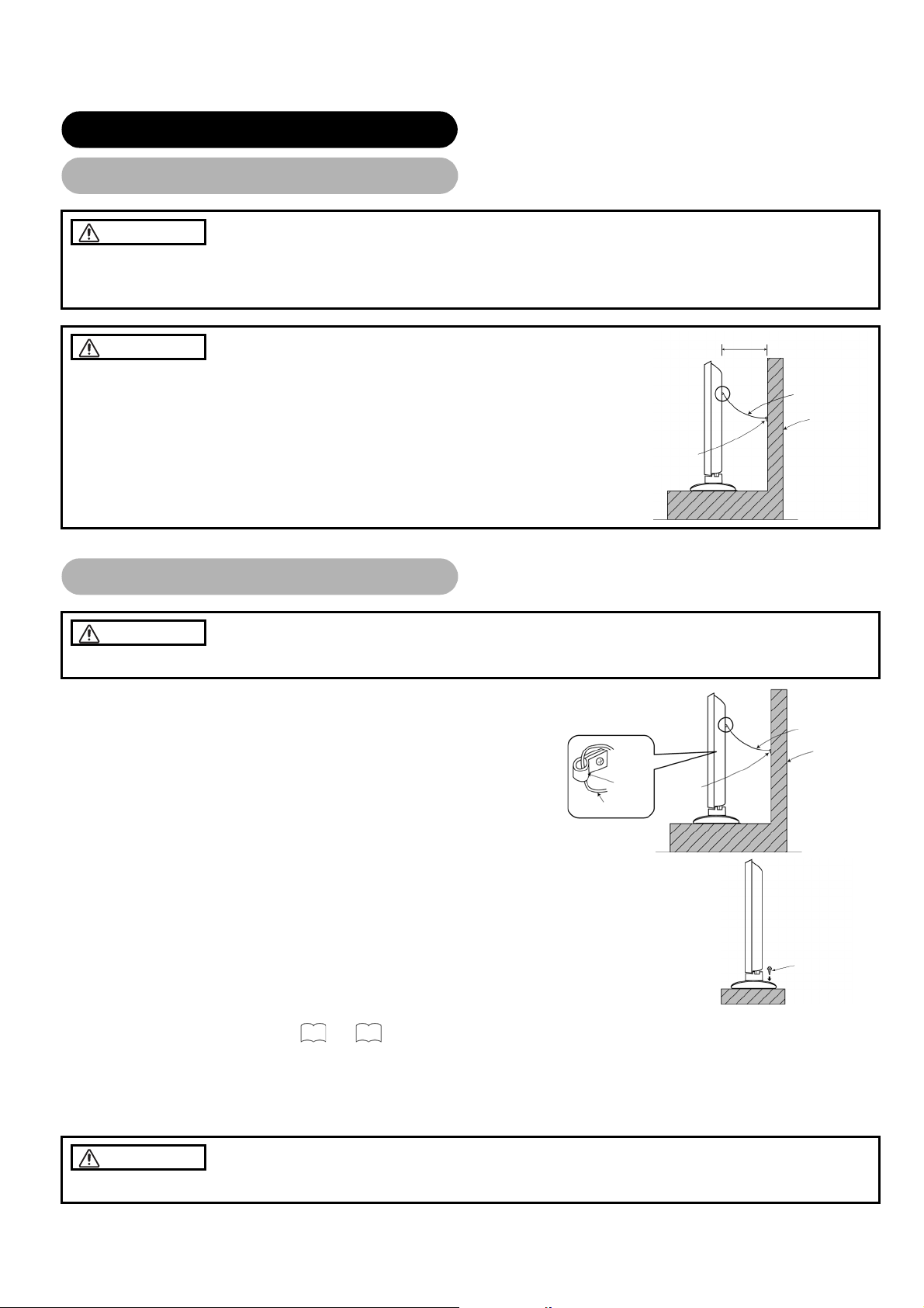
Have this unit mounted in a stable place. Take measures to prevent it from tumbling down to avoid possible physical injury.
Securing to a wall or pillar
Using a commercially available cord, chain and clamp, secure the set to a firm wall
or pillar. ( There are two hooks on both sides of the rear panel.)
Cord or chain
Cord or chain
Wall or Pillar
Wall or Pilla
Hook
Cord or chain
Clamp
Securing desktop
(1) Using wood screws (two), fasten the set to the clamping screw holes on the rear of the stand
as shown.
(2) Using commercially available wood screws, secure the set firmly in position.
Read SAFETY INSTRUCTIONS (
3
to
6
) carefully to ensure maximum safety before proceeding to these
steps:
• Choose an appropriate site and install the product on a level table where the stand is secure.
• Install the monitor to have ready access to a power socket available.
• Make sure that the power switch of this device is turned off.
CAUTION
Loosen a cord or chain enough to avoid possible troubles whilst operating power swivel.
Wood screw
Two pl aces
12
Page 14
*1
INSTALLATION INSTRUCTIONS (continued)
Connection to an Audio Visual Device
Connection to an Audio Visual Device
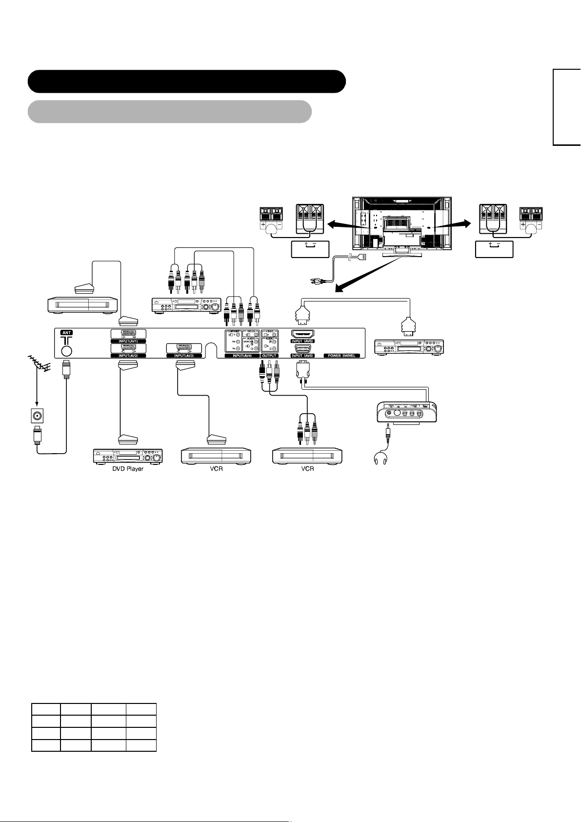
(1) Make sure that the power switch of the monitor is turned off.
(2) Make sure that the power switch of the audio visual device is turned off.
(3) Use a commercially available cable and connector to connect the signal input terminal on the rear panel of this device
and the signal output terminal of the audio visual device.
Antenna
Set-Top Box
To audio output
terminals
To SC AR T
input/output terminal
DVD Player
To component
output terminals
Speaker (R)
SPEAKER TERMINAL
(6Ω 12W)
HDMI*
Power
Cord
Monitor (rear panel)
DVD Player
Speaker (L)
SPEAKER TERMINAL
(6Ω 12W)
ENGLISH
Headphone
Side Input
To S, composite
audio output
terminals
To SCART
output terminal
To SCART
output terminal
input terminal
To audio input
terminals
To Composite
*1 If you are connecting a satellice or cable receiver that does not require a Tuner output signal
from the SCART, then for the bet results you can connect to AV2 or AV3.
• AV1 SCART applies to composite/S-Video, and AV2 and AV3 SCART apply to composite/RGB.
• If a component input terminal and a composite input terminal of AV4 connect to the monitor at the same time, the component input would
[An example of connecting audio visual devices]
govern.
• If a video equipment with an S-Video output terminal is used, cabling by the S-Video cable is recommended to provide finer video quality.
(If an S-Video input terminal and a video input terminal of AV5 (side input) connect to the monitor at the same time, S-Video input would
govern.)
• If the OUTPUT (Monitor) terminal is connected to an external monitor with a 75 Ohm terminal, it is possible to view the same image as on
the main unit. But it is possible to monitor only the composite video signal from AV1 ~ AV5 input that is displayed on the screen at the time.
• Set -Top Box is only for an AV1 input.( Tuner output signal is available only for AV1.)
• Secure connecting cables to the stand with the provided clamps.
HDMI*
• HDMI (High-Definition Multimedia Interface) is a digital interface based on DVI (Digital Visual Interface), which is an added function for
audio visual equipment.
- It does not have degradation by transmission since it is digital.
- With only one cable, it is possible to transmit both picture signals and audio signals.
• In case of using analogue audio when connecting with DVI-HDMI transformation connector, use analogue audio terminal for AV4 input.
SCART Specification
CVBS S-Video RGB
AV1
AV2
AV3
○ ○ ―
○ ― ○
○ ― ○
13
Page 15

INSTALLATION INSTRUCTIONS (continued)
Connection to an Audio Visual Device (continued)
Precautions when connecting the antenna
• Please use a coaxial cable which is free from interference to connect the antenna. Avoid using a parallel flat feeder wire as interference
may occur, causing reception to be unstable and stripe noise to appear on the screen.
• Avoid using indoor antenna as this may be affected by interference. Please use CATV net or outdoor antenna.
• Keep the power cord as far away from the antenna wire as possible.
If there are noise appearance in the picture of VHF-Low band channel, please use the double-shielded cable (not provided) for RF
LEADS to reduce the noise.
14
Page 16
A
INSTALLATION INSTRUCTIONS (continued)
Connecting to a PC
Connecting to a PC
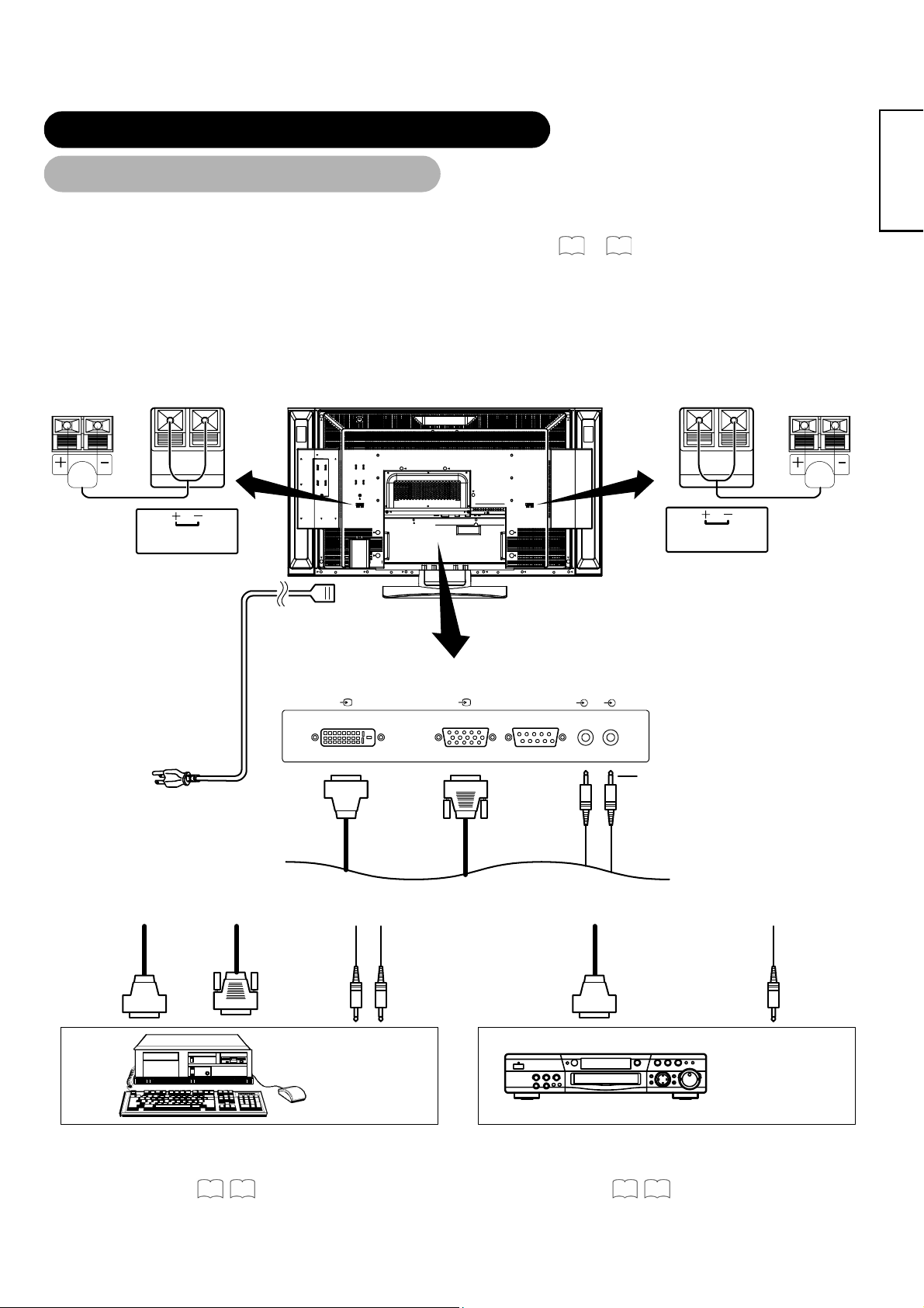
(1) Make sure that the display signal of the personal computer to be used is compatible with the specifications of this
device.
• See "PRODUCT SPECIFICATIONS" concerning the specifications of this device.
(2) Make sure that the power switch of the personal computer is turned off.
(3) Connect the signal input terminal (RGB 1 or RGB 2) on the rear panel of this device to the display signal output terminal
of the personal computer.
• Use a cable that fits the input terminal of this device and the output terminal of the personal computer.
• Depending on the type of personal computer being connected, the use of an optional conversion adapter or the adapter provided with
the personal computer may be necessary in some cases. For details, refer to the instruction manual of the personal computer or ask
the personal computer manufacturer or your local retail dealer.
Speaker (R)
SPEAKER TERMINAL
(6Ω 12W)
Monitor (rear panel)
50
~ 52
Speaker (L)
SPEAKER TERMINAL
(6Ω 12W)
ENGLISH
To signal
output
terminal
(DVI)
Power cable
connector
DIGITAL INPUT
RGB 1
PC PC
ANALOG INPUT
RGB 2
RGB 1
UDIO IN
RGB 2
3.5 mm
Power cord
(DVI) (D-SUB)
Stereo
mini jack
Connecting to a PC Device Connecting to an Audio Visual Device
To signal
output
terminal
(D-sub)
PC
To audio
output
terminal
To signal
output
terminal
(DVI)
To audio
output
terminal
(Example)
DVD Player
• Setting
RGB1: DVI-PC
RGB2: RGB
For details, refer to
51 52
• Setting
RGB1: DVI-STB
RGB2: Component
For details, refer to
50 51
15
Page 17
INSTALLATION INSTRUCTIONS (continued)
Connecting the Speaker Cables
Connecting the Speaker Cables
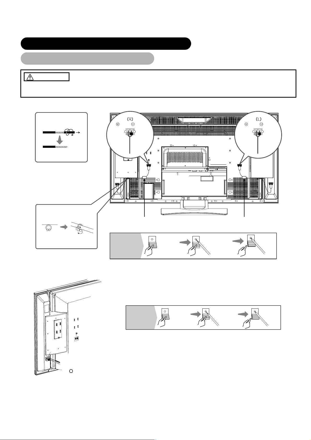
CAUTION
Make sure that the main power switch of the monitor is turned off (standby or indicating lamp: off/red) when removing or connecting
the speaker cables.
1. Attach the speaker connecting cables to the monitor. (Make sure the ferrite core is toward the monitor side)
Treating the wire ends
Pull off whilst twisting
Please prepare the supplied
speaker cables
Red Black
Connect the
red coloured
wire
Connect the
red/black
coloured wire
Red Black
Connect the
red coloured
wire
Connect the
red/black
coloured wire
Twist the
heads
How to connect
the speaker
cables
2. Attach the speaker cables to speaker systems.
Speaker
terminal
Connect the red/black - coloured
wire to the Θ Black side.
Connect the red - coloured wire to
the + Red side.
Ferrite core
How to connect
the speaker
cables
Press down
the lever
Hold down
the lever
Insert the
wire
Insert the
wire
Ferrite core
Release
the lever
Release
the lever
16
Page 18
INSTALLATION INSTRUCTIONS (continued)
Mounting the Side Input
Mounting the Side Input
1. Mount the side input into the speaker holder.
Hook the clamps (4 pieces) of the speaker holder into the holes as shown in the figure and pull them down until it sounds click.
Fasten the side input with the speaker holder by the accessory screw .
Refer to
13
about the connection of side input.
See the below figure how to treat the cable.
Side input
Speaker Holder
2. Mount the side input into the holder on rear of the monitor.
Fasten the side input with the holder by the accessory screw.
See the below figure how to treat the cable.
Screw X 1
(Included with side input)
Side Input cable
ENGLISH
Side Input cable
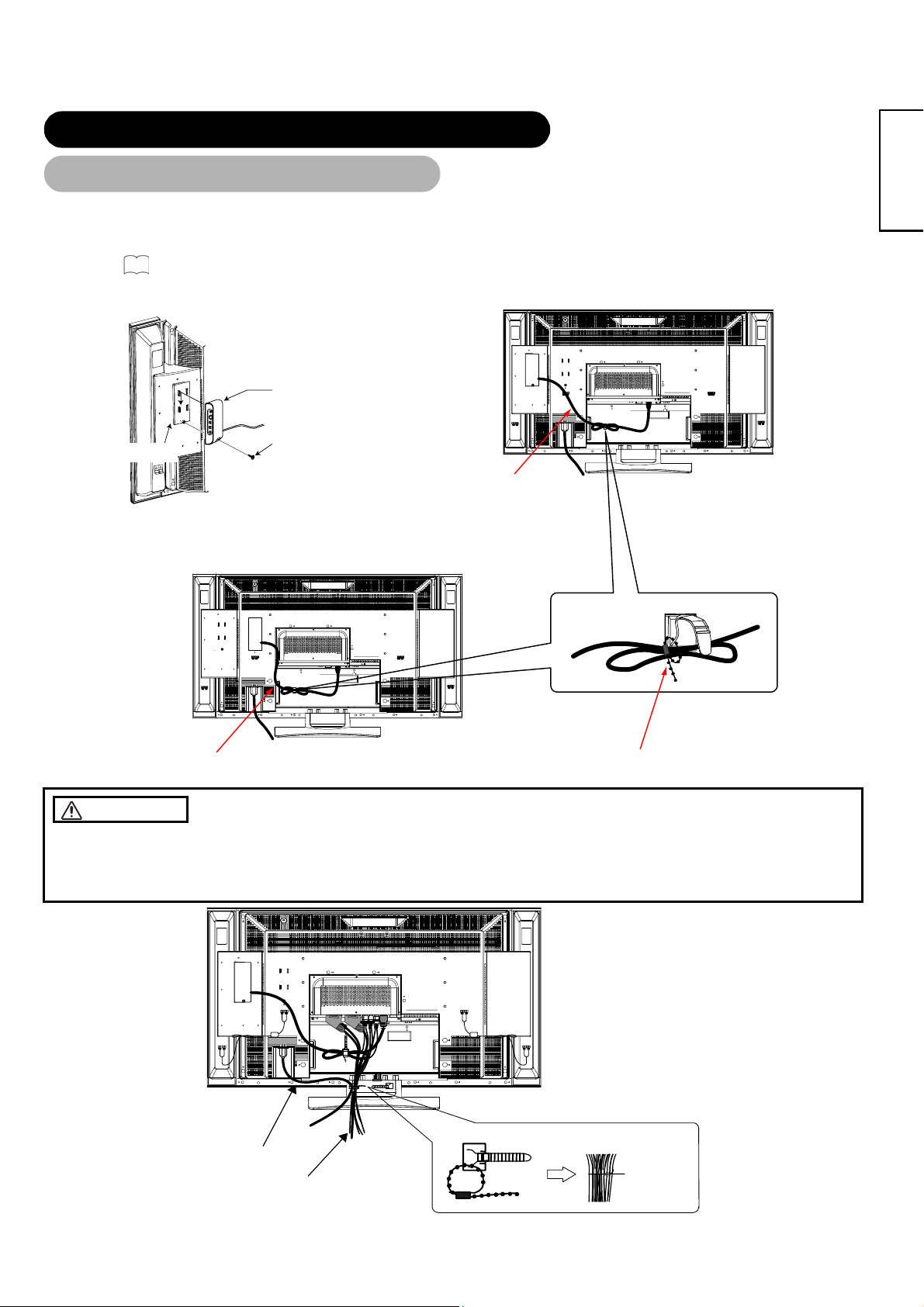
CAUTION
Cable strap
Make sure to secure the power cable and the connecting cables for other audio visual devices, except the speaker connecting
cables, with the clamps and the cable strap of the monitor stand and the rear of it. When the monitor is swiveled, the connectors
may drop out and generate heat. It could cause fire and/or connector failures.Moreover, when wiring up and securing these cables,
give suitable slack not to rub the stand during swiveling or not to block the action of swivel.
[An example of treating the cables]
Bundle the cables
to be secured
Power cord
Connecting
cable
17
Page 19

INSTALLATION INSTRUCTIONS (continued)
Power Cord Connection
Power Cord Connection
Connect the power cord, after completing all other connections.
UK only
Europe
(1) Connect the power cord to this device.
(2) Connect the power cord plug to the power outlet.
(The type of plug is different from this drawing for some countries.)
CAUTION
• Use only the power cord provided.
• Do not use a power supply voltage other than that indicated (AC100-240V, 50/60Hz) as this may cause fire or electric shock.
18
Page 20

OPERATING INSTRUCTIONS
OPERATING INSTRUCTIONS
POWER button
Indicating lamp
Main power switch
SUB-POWER button
Turning Power On and Off
Turning Power On and Off
• To turn the monitor power ON, press the main power
switch on the monitor main unit to ON, and then press the
SUB POWER button of control panel or the POWER
button on the remote control.
• To turn the monitor power OFF, press the SUB POWER
button of control panel or the POWER button on the
remote control, and then press the main power switch on
the monitor main unit to OFF.
• During normal use, the main power switch is set in the ON
position, and the monitor can then be turned ON/OFF using the
SUB POWER button or the POWER button on the remote
control.
Indicating lamp
Indicating
lamp
Off Off
Lights red
Lights green
Lights orange
When the indicating lamp lights in orange or the message "No
Sync. Signal", "Power Save" or "Invalid Scan Freq." appears on
the screen, there is something unusual about the status of
reception. See "Power Save Mode" or "Symptoms That
Seemingly Appear to be Failures."
ATTENTION
• Avoid repeatedly turning the monitor on and off at short time
intervals. Failures might result from such operation.
• Turn off the main power switch before leaving the monitor out of
use for an extended period of time.
• If a power failure occurs whilst the main unit is running, it would
be powered on upon recovery from the failure. Turn off the unit
main power switch before leaving the main unit.
Power
status
Off
(standby)
On
Off
(Power Save)
Operating
When the main power switch is set to
OFF.
When the main power switch is ON, and
the POWER button on the remote control
or the SUB POWER button on the upside
of the monitor is OFF.
When the main power switch is ON, and
the POWER button on the remote control
or the SUB POWER button on the upside
of the monitor is ON.
When the main power switch is ON, and
the POWER button on the remote control
or the SUB POWER button on the upside
of the monitor is ON.
However, the state is in POWER SAVE
mode.(RGB 1 and RGB 2 only.)
43
45
44
ENGLISH
19
Page 21

OPERATING INSTRUCTIONS (continued)
A
A
A
A
INPUT SELECT button CHANNEL UP/DOWN buttons
RECALL button
INPUT SELECT
buttons
Input Switching
Input Switching
• Input can be switched by pressing the AV1~6, RGB1 or
RGB2 buttons of the remote control.
• Input can be switched to TV by pressing CHANNEL
UP/DOWN button or PROGRAM SELECT buttons.
• Input can be switched in the sequence of TV → AV1 →
AV2 → AV3 → AV4 → AV5 → AV6 → RGB1 → RGB2
by pressing the INPUT SELECT button of the control
panel.
TV AV1 AV2 AV3 AV4
V5
V6 RGB1 RGB2
Size Switching
Size Switching
Each time the ZOOM button of the remote control is pressed,
the screen display size will change in sequence and the
status will be displayed at the bottom of the screen.
• During TV/VIDEO signal input (AV4, AV5, AV6, RGB1(set
to [DVI-STB])and RGB2(set to [Component]))
Panoramic
14:9Zoom C14:9L Zoom
• The size will fix as Full mode and not change when receiving the
4:3 Full
component signal of 1080i/50, 1080i/60, 720p/50 or 720p/60.
Full
Display size selection diagram
When you want to Set the display size to Input signal Display screen Remarks
CHANNEL
UP/DOWN
button
PROGRAM
SELECT
buttons
ZOOM button
• During AV1 ~ AV3 signal input
uto
14:9Zoom C14:9L
• [Auto] is the mode using the Switch signal from the equipment
Full
connected to AV1~AV3 terminal included in SCART connector
No.8 pin which indicate the picture format of the video source.
When Switch signal has not been detected, Default Zoom setting
in the Function Menu is used to choose.
• During TV mode
uto
14:9Zoom C14:9L
• [Auto] is the mode using WSS (Wide Screen Signals) which
Full
identify the picture format movies and programs are broadcast in.
Various broadcast stations now transmit WSS. It can be detected
and the monitor automatically switch to the correct format.
However, some broadcasters do not transmit WSS, so this
monitor will not recognise which format is being transmitted.
Therefore, Default Zoom setting in the Function Menu is used to
choose when a WSS has not been sent or has not been detected.
Zoom
Zoom
Play a 4:3 image in a 16:9 screen faithfully.
Play a 4:3 image in a 16:9 screen with the
height and width of the middle of the screen
enlarged on equal scales and with both sides
appearing somewhat enlarged.
Play a 16:9 VISTA size image in the 4:3 image
faithfully reproduced on the 16:9 screen.
Play a 4:3 image faithfully in a 16:9 screen in
the standard vertical size and horizontally
squeezed.*
4:3
Panoramic
Zoom
Full
(Vista)
(4:3 signal)
(Squeeze)
Blanking occurs on both sides.
• The 4:3 image is called a letterbox
image.
• In some cases, some slight blanking
may remain at the top and bottom.
* An image with an aspect ratio of 16:9
shrunk horizontally to 4:3 to display in a
4:3 screen.
20
Page 22

OPERATING INSTRUCTIONS (continued)
Size Switching (continued)
When you want to Set the display size to Input signal Display screen Remarks
Play a 14:9 image in a 16:9 screen expanded
vertically and squeezed horizontally.
Play a 14:9 image expanded vertically on the
16:9 screen.
C14 : 9L
14 : 9Zoom
Vertical picture position can be adjusted for [Panoramic], [Zoom], [C14:9L] and [14:9Zoom] mode as follows.
1. Press ZOOM button and
ST SELECT buttons during picture size display.
2. Position display will appear.
3. Adjustment range of each picture size are as shown below.
[Panoramic] - 12 to + 12
[Zoom] - 31 to + 31
[C14:9L] and [14:9Zoom] - 16 to + 16
4. When 1080i/60 component signal is received, vertical position can be adjusted only one step up. (The range: 0 to +1)
(14:9 signal)
(14:9 signal)
This mode is provided for the broadcasting
program with WSS code-C14:9L.
This mode is provided for the broadcasting
program with WSS code-14:9 Zoom.
ENGLISH
Position - 31Position + 31
Press S Press T
ATTENTION
Using a wide-screen monitor
• This monitor has a screen mode selection feature. If an incompatible screen mode is selected to play certain software, such as a TV
program, the image would appear different from the original. Take this into consideration when making screen mode choices.
• Use of this monitor in its enlarged display mode with the wide feature enabled in coffee shops, hotels and other establishments for
commercial or public viewing purposes could infringe on the copyright holder's right protected by Copyright Law.
• When a normal 4:3 image is displayed over the entire screen in the Panoramic mode, parts of the periphery of the image may disappear
and/or appear distorted in some cases. Use the 4:3 mode to view images, which were created in 4:3 mode.
• This mode allows 4:3 content to be viewed without picture distortion.
• During RGB Input (RGB1 (set to [DVI-PC]) and RGB2 (set to [RGB]))
Normal Full Zoom1
Real*
* Real mode gives the image of the same shape as it is displayed on a computer monitor.
Zoom2 Zoom3
This mode is only available for VGA (640 X 480), WVGA (864 X 480),SVGA (800 X 600),XGA (1024 X768) and WXGA (1280 X768).
Display area selection diagram (RGB input)
Resolution Full display Circular display
Display Full Normal Real Zoom1 Zoom2 Zoom3
640 X 480 (VGA)
800 X 600 (SVGA)
1024 X 768 (XGA)
1280 X 1024
1600 X 1200
(UXGA)
1366 X768
(SXGA)
(WXGA)
Selected character
WXGA Type
32
can't select
Processes such as compression (thinning) and expansion are performed for the above signal display. Because of this, there is a
possibility that flicker may become noticeable on Zoom (1 ~ 3) depending on the display contents. If this occurs, turning the Vertical
33
Filter on
can reduce the flicker.
21
Page 23

OPERATING INSTRUCTIONS (continued)
Volume Adjustment
Volume Adjustment
The volume can be adjusted by pressing the and
buttons of the remote control (or the
buttons of the monitor unit).
Volume setting value
Volume 15
Adjustment status guide display
• When a button is pressed, the volume adjustment status
guide will be displayed.
• The volume will increase when the button is pressed whilst
the guide is being displayed.
• The volume will decrease when the button is pressed
whilst the guide is being displayed
and volume
Audio Mute
Audio Mute
The audio volume can be temporarily muted by pressing the
MUTE button of the remote control.
Volume setting value
Volume 15
Adjustment status guide display
(The display colour will change to magenta : volume
• When a button is pressed, the volume adjustment status
guide (magenta) will be displayed.
• The volume setting can be lowered by pressing the button
whilst the audio is mute.
• The muting can be cancelled by pressing the button or
MUTE button whilst the audio is mute.
• The audio from the headphone terminal is not mute.
• The audio from the speaker is automatically mute whilst
connecting the headphone to the headphone terminal of the
side input (AV5).
When the MUTE button of the remote control is pressed
again, the audio will be restored and the volume display
(green) will appear.
→Mute)
22
Page 24

OPERATING INSTRUCTIONS (continued)
Power Swivel
Power Swivel
• This feature controls the motorised stand. It allows turning the LCD monitor left or right using the remote control.
WARNING
Make sure that the main power switch of the monitor is turned off when removing or connecting the power cord, the connector
cables, and the speaker cables.
1. Press Swivel button.
The controlling icon appears on the screen.
• If the connecting cable is not connected, the indication "Not Available" appears.
• The swivel display disappears in about 6 seconds without any operation.
Swivel
2. Adjust for preferred angle.
Opposite directions are displayed on the screen whilst the monitor is swiveled.
Adjust by using
Swiveling angle of the monitor is available within ±30 degrees from the front face.
ATTENTION
• Do not push the panel manually whilst using the swivel function. It could cause damage to the stand or the panel.
• Do not get on and hang from the monitor. Do not swing the monitor back and forth and around either. It could cause a failure of the
stand.
• Do not put hands or faces close to the monitor whilst operating the swivel function. It could cause a physical injury. Use special caution in
households where children are present.
• Do not put any object, like a vase, near the monitor in swiveling area. It would cause a breakage of the object and /or a failure of the
stand.
• Place the monitor on the stable location, or the swivel function would not operate correctly. It would cause a malfunction.
• In the case of using the monitor wall mounted, be sure to detach the connecting cable between the monitor and the stand.
Caution when connecting the monitor with the stand
key whilst the swivel display is on the screen.
ENGLISH
• When detaching the stand from
the monitor, make sure to
detach the connector cable from
the stand connection terminal on
• When attaching the stand to the monitor
once again, insert the connector cable into
the stand connection terminal on the rear
of the monitor.
the rear of the monitor.
Pinch right and
left locks of the
connector and pull
out downward.
• Make sure that the direction of the connector for stand connecting cable is correct.
Insert until it clicks.
23
Page 25

OPERATING INSTRUCTIONS (continued)
Input Signal Screen Display
Input Signal Screen Display
The input signal status can be displayed on the
screen by pressing the RECALL button of the remote
control.
• The display will go out in approximately 6 seconds.
TV
Off-timer
On-timer
VIDEO
Min.
ABCDE
AV1
Composite
1
RECALL button
TV position
Name
Sound mode
Input mode
Signal mode
Off-timer
On-timer
RGB
Off-timer
On-timer
Min.
Min.
RGB2
RGB
: 48.4kHz
H
V : 60.1kHz
Input mode
Signal mode
Input horizontal frequency
Input vertical frequency
24
Page 26

OPERATING INSTRUCTIONS (continued)
Displaying MULTI PICTURE
Displaying MULTI PICTURE
When the MULTI PICTURE button on the remote control is
pressed, the screen will display the multi pictures. And then
three types of the screen can be selected by pressing the
MULTI MODE button on the remote control.
The multi-picture mode will change in the following
sequence each time the MULTI MODE button is pressed.
2 pictures (Split) 4 pictures 12 pictures
Activating the Split mode from the TV screen
Pressing the MULTI PICTURE button one time will display 2 pictures.
• The speaker icon can be shifted left and right by pressing the W and XSELECT buttons; the audio will be
output from the side on which the speaker icon is located.
• The same signal input cannot be selected for both screens at the same time.
• The TV channel can be changed by pressing the CHANNEL UP/DOWN button on the remote control.
• The signal input mode of picture-A or picture-B (the one that the speaker icon is located on) can be
selected by pressing INPUT SELECT buttons on the remote control.
• Pressing the MULTI PICTURE button once again will cancel the multi-picture mode.
• Refer to the table for 2 pictures (Split) mode.
26
Activating the 4 pictures mode from the TV screen
Pressing the MULTI MODE button one time at the 2 pictures mode will display 4 pictures.
• Press W and XSELECT buttons to select picture A or picture B indicated by a red triangle. For pictures on
right, press S and T SELECT buttons to select picture. The selected input display number would change
green.
• The TV channel can be changed by pressing the CHANNEL UP/DOWN button on the remote control.
• The audio can only be output from picture A in 4 pictures mode.
• The component signal input mode cannot be selected in pictures B. Refer to the table for 4 pictures
mode.
• Pressing the MULTI PICTURE button at the 4 pictures mode will cancel the multi-picture mode. And then,
pressing the MULTI PICTURE button again will display the 4 pictures.
26
Activating the 12 pictures mode from the TV screen
Pressing the MULTI MODE button one time at the 4 pictures mode will display 12 pictures.
• Starting from channel 1, preset channels will automatically display in sequence on the 12 windows.
• This function activates only in TV mode.
• After several seconds, it refreshes the picture one by one.
• Pressing the MULTI PICTURE button at the 12 pictures mode will cancel the multi-picture mode. And
then, pressing the MULTI PICTURE button again will display the 12 pictures again.
• Pressing the MULTI MODE button at the 12 pictures mode will display the 2 pictures (Split) mode.
INPUT SELECT
buttons
MULTI MODE
button
RECALL button
SELECT/ADJUST
button
(S, T, W, X)
CHANNEL
UP/DOWN button
MULTI PICTURE
button
ENGLISH
25
Page 27

OPERATING INSTRUCTIONS (continued)
A
A
Displaying MULTI PICTURE (continued)
1080i/
60
1080i/
60
720p/
50
720p/
50
V1
RGB2
AV1
720p/
STB Component
60
{
{
{
{
{
{
{
{
{
{
Teletext is available only for TV
720p/
STB Component
60
TELE
TEXT
{
({ : Available)
TELE
TEXT
({ : Available)
Main
Main
Sub
▼
Activating the Split mode from the video input screen
Pressing the MULTI PICTURE button one time will display 2 pictures.
• The speaker icon can be shifted left and right by pressing the and SELECT buttons. The audio of the
video will be output from the side on which the speaker icon is located.
• The same video input mode cannot be selected for both screens at the same time.
• Pressing the MULTI PICTURE button again will cancel the 2 pictures display.
• Refer to the table for 2 pictures (Split) mode.
Activating the MULTI PICTURE mode from the RGB input screen
Pressing the MULTI PICTURE button one time will display 2 pictures.
• This mode can be available from RGB1 (DVI-PC) and RGB2 (RGB) input.
• The speaker icon can be shifted up and down by pressing the and SELECT buttons. The audio will be
output from the side on which the speaker icon is located.
• The sub-screen position can be selected up and down by pressing and SELECT buttons.
• The sub-screen can be selected with the AV1~AV6, TV channel buttons from the status that the speaker icon
appears on the left side of AV* etc. as shown in the diagram to the right.
• Pressing the MULTI PICTURE button again will cancel the 2 pictures display.
AV1: Displays the VIDEO input signal of the sub-screen.
NOTE
• Even if the input of the horizontal / vertical synchronizing signal (or video signal) stops in the multi picture display, the mode will not
change to power save mode.
2 Pictures (Split) [TV / Video Input]
Input terminal AV1 ~ AV5 AV2,AV3 AV4, AV6 RGB1 RGB2
Sub
Main
AV1
~ AV5
AV2
AV3
AV4
AV6
RGB1 STB
RGB2 Component
TV
PAL, SECAM
NTSC3.58/4.43
RGB
576i, 576p
480i, 480p
1080i/50
1080i/60
720p/50
720p/60
PAL
SECAM
{ {
NTSC3.58
NTSC4.43
{ { { { {
{ { { { {
TV
{ { {
{
{ { { { { { {
{
{ { { { { { {
{
{ { { { { { {
{
{ { { { { { {
{
{ { { { { { {
{
{ { { { { { {
{ { { { { { { {
{ { { { { { { {
RGB
576i
576p
480i
480p
1080i/
50
4 Pictures [TV / Video Input]
Input terminal AV1 ~ AV5 AV2,AV3 AV4, AV6 RGB1 RGB2
Sub
Main
AV1
~ AV5
AV2
AV3
AV4
AV6
RGB1 STB
RGB2 Component
TV
PAL, SECAM
NTSC3.58/4.43
RGB
576i, 576p
480i, 480p
1080i/50
1080i/60
720p/50
720p/60
PAL
SECAM
{ {
NTSC3.58
NTSC4.43
{
{
TV
{ { {
{
{ { {
{
{ { {
{
{ { {
{
{ { {
{
{ { {
{
{ { {
{ { { {
{ { { {
RGB
576i
480i
480p
1080i/
50
576p
NOTE
About 720p/50 Hz
• 720p/50Hz can support for AV4, AV6 and RGB1 (DVI-STB) only during the single picture mode.
• RGB2 (composite) is not available for 720p/50 Hz.
V2
(Subscreen)
Sub 1
Sub 2
Sub 3
26
Page 28

A
OPERATING INSTRUCTIONS (continued)
FREEZE button
ENGLISH
Picture Freezing
Picture Freezing
When the FREEZE button on the remote control is pressed, the screen transfers into the
freeze mode.
• There are two types of freezing screen mode, Split and Strobe. These are possible to select at the
"Freeze Mode" setting of the Function Menu.
• The Split mode will display 2 pictures from the same source on the screen with one active picture and
the other still.
• The Strobe mode will display 12 pictures with the last picture active, whilst other 11 windows are still.
• Pressing the FREEZE button again changes the screen back to the normal picture.
• This function is also available from video input mode besides TV mode. Refer to the table for Freeze
function as below:
Split Strobe
TV O O
PAL, SECAM O O
NTSC3.58/4.43 O O
SCART(RGB) O O
576i O O
480i O O
576p O
480p O
1080i/50 O
1080i/60 O
720p/50
720p/60 O
RGB. DVI-PC/STB
( O : Available )
[Split]
[Strobe]
A
′
27
Page 29

OPERATING INSTRUCTIONS (continued)
RECALL button
MENU button
OK button
RETURN button
SELECT/ADJUST
button
(, , , )
Using the Menu Screen
(On-screen display system)
Using the Menu Screen
When the MENU button of the remote control or the control
panel is pressed, the adjustment menu screen will be displayed;
from there, several adjustments and settings are possible by
using the SELECT button, ADJUST button and OK button.
• Refer to
settings
- 41 concerning the adjustment items and the
29
Example: Selecting the Picture screen from TV/Video mode
1. Press the MENU button to display the Main Menu screen.
2. Press the OK button to display the Picture Menu screen.
(Use the and SELECT buttons to select other items.)
3. Use the and SELECT buttons to select the item to be
adjusted and then use the and ADJUST buttons to
adjust (example: Contrast).
• Press the RETURN button to return to the previous screen.
• If there is no operation for a period of one minute, the Adjustment
Menu screen will be closed automatically.
28
Page 30

OPERATING INSTRUCTIONS (continued)
SETUP MENU (TV mode)
SETUP MENU (TV mode)
ENGLISH
29
Page 31

OPERATING INSTRUCTIONS (continued)
SETUP MENU (TV mode) (continued)
Selected characters
Auto Tuning
Country
Search
Manual Tuning
Position
Search
(C--)
(S--)
(--MHz)
Descrambler
Name
− −
− −
− −
− −
− −
Off On
(:a letter)
Setup hint
Select the country name by and SELECT buttons and press OK button.
• If some required stations could not be preset in this auto tuning function,
select and preset the required station in the required position by the
manual tuning operation.
Press the OK button and it starts the auto tuning.
Set the position number (1~199 and AV00) or channel number by ( + ) ( - )
CHANNEL UP/DOWN button.
At first, select the channel entry method, entering a two digit channel
number(CH), entering a two digit S-band number or entering a three digit
frequency(MHz), by pressing the OK button.
Enter two digit number by pressing 0~9 NUMBER buttons. If the number is
normal, then it starts the channel search.
Enter two digit number by pressing 0~9 NUMBER buttons. If the number is
normal, then it starts the channel search.
Enter three digit number by pressing 0~9 NUMBER buttons. If the number is
normal, then it starts the channel search.
Set this to Off normally. If it is set to On, AV1 (Scart) terminal operates as TV
signal output, and the screen changes to display AV1 (Scart) input signal
automatically.
This is used to input the name of the TV station within 5 letters. After fixing
the cursor on the first digit, select a letter by and SELECT buttons and
move to next digit by ADJUST button. Press the OK button again after
finished.
• Selectable letters are "0"~"9", "A"~"Z", "+", "-", " "(Blank),"," (comma) and
"."(Period).
Sound System
Colour System
Skip
Fine Tuning
Sort
(A Line of position List)
Teletext Language
Auto Off
Auto PAL SECAM
NR
Decreasing the frequency data
for the main tuner
NTSC3.58 NTSC4.43
Off On
Off On
Increasing the frequency data for
the main tuner.
− −
− −
Off On
Select the sound system through the 5 different settings.
Select the colour system through the 5 different settings.
If this is set to On, that position will be skipped whilst selecting positions by
CHANNEL UP/DOWN button.
This is automatically set to On for those non-broadcasting channels.
If this is set to On, it helps to reduce the noise interference visible on the
screen, especially in the weaker signal reception areas.
After completing the fine-tuning, press the RETURN button to exit this mode.
• The variable range is -56 ~ +56.
Press OK button at a line that is required to change order, then the
characters will change to green. And move it up or down in the list by
pressing and SELECT buttons. And press OK button to complete it.
Press the RETURN button to exit.
Select the Teletext Language, depending on the area utilized through the 4
settings: West Europe, East Europe, Cyrillic and Greek/Turkish.
If this is set to On, the power will be turned off when there is no transmission
signal and no operation for about 10 minutes in the TV mode.
30
Page 32

A
A
OPERATING INSTRUCTIONS (continued)
SETUP MENU (Video mode)
SETUP MENU (Video mode)
Selected characters
System
Colour System
AV1 ~AV5
Video Input
Scart Output
RGB1
RGB2 (1st step)
RGB2 (2nd step)
AV1
AV4
System1 System2
System1
Auto PAL SECAM
NTSC3.58 NTSC4.43
System2
Auto NTSC-M
PAL -N PAL-M
S. Video Composite
uto
HDTV SDTV/DVD
TV Monitor
DVI-PC DVI-STB
RGB Component
uto
HDTV SDTV/DVD
ENGLISH
Setup hint
Do not change the original setting.
(System1: Europe/Asia, System2: North America)
This should correspond to the colour system of the signal from the
equipment that is connected to AV1~AV5 video input terminal.
• Normally, set this to Auto. The system of the input signal will be
automatically recognised.
• If the input signal contains much noise or has a low level at Auto and the
operation is found erratic, set this to match the input signal.
• When the component signal is received, this would be not available
(greyed out).
This should correspond to the signal mode of the signal from the equipment
that is connected to AV1 Scart input.
This should correspond to the signal mode of the signal from the equipment
that is connected to AV4 video input terminal.
• Normally, set this to Auto. The signal mode of the input signal will be
automatically recognised.
• If the input signal contains much noise or has a low level at Auto and the
operation is found erratic, set this to match the input signal.
TV : AV1 (Scart) output will be fixed as TV signal output.
Monitor : AV1 (Scart) output can view the image as on the main unit. But it is
possible to monitor only the composite video signal from AV2, AV3, AV4 or
AV5 input that is displayed on the screen at the time.
• If Descrambler is set to On, it will be fixed as TV automatically.
This should correspond to the signal mode of the signal from the equipment
that is connected to RGB1 DVI terminal.
This should correspond to the signal mode of the signal from the equipment
that is connected to RGB2 D-sub terminal.
This step should be set only when [Component] is selected on the 1st step.
This should correspond to the signal mode of the signal from the equipment
that is connected to RGB2 D-sub terminal.
• Normally, set this to Auto. The signal mode of the input signal will be
automatically recognised.
• If the input signal contains much noise or has a low level at Auto and the
operation is found erratic, set this to match the input signal.
31
Page 33

OPERATING INSTRUCTIONS (continued)
SETUP MENU (RGB mode: RGB1 (DVI-PC), RGB2 (RGB))
SETUP MENU (RGB mode: RGB1 (DVI-PC), RGB2 (RGB))
Selected characters
Auto Adjust*
Horizontal Position
Vertical Position
Horizontal Clock
Clock Phase
Reset
Input Level
Frequency Display
WVGA Type
WXGA Mode
−
Moves the horizontal position to
left.
Moves down the vertical position Moves up the vertical position.
Reduces the dot clock frequency
(shrinks the right side).
Slows the dot clock phase (shifts
slightly to left).
(off the function) (waiting to reset)
Pressing the OK button here,
Automatic regulation is started.
Moves the horizontal position to
right.
Increases the dot clock
frequency (expands the right
side).
Advances the dot clock phase
(shifts slightly to right).
Adjust
Off On
Off On
Off
Setup hint
Horizontal Position, Vertical Position, Horizontal Clock and Clock Phase are
adjusted automatically.
Adjust the left-side display position.
Screen display changes to Magenta colour if beyond the available range.
(This function is only for RGB2. It's not available (greyed out) for RGB1
(DVI-PC).)
Adjust the vertical display position.
Screen display changes to Magenta colour if beyond the available range.
(This function is only for RGB2. It's not available (greyed out) for RGB1
(DVI-PC).)
Adjust for maximum character clarity.
(This function is only for RGB2. It's not available (greyed out) for RGB1
(DVI-PC).)
Adjust for clear character visibility.
(This function is only for RGB2. It's not available (greyed out) for RGB1
(DVI-PC).)
The original factory settings for the items of this Menu page can be restored
by pressing the OK button.
Normally set to 0.7 V. If white is found to spread across the screen, set to 1.0
V. (This is effective only for RGB2.)
Set this to Off if the frequency information of the Input Signal Screen Display
is not required.
This is only available for W-VGA signal.
When it is set to On, the display area mode can be selected Full or Real.
(With RGB1 INPUT, the screen remains the same. RGB2 (ANALOGUE)
INPUT only)
This is only available for W-XGA signal.
(RGB2 (ANALOGUE) INPUT only)
32
Page 34

A
OPERATING INSTRUCTIONS (continued)
SETUP MENU (RGB mode: RGB1 (DVI-PC), RGB2 (RGB)) (continued)
Selected characters
Vertical Filter
Frequency Mode
RGB1
RGB2 (1st step)
RGB2 (2nd step)
* Depending on the type of signal displayed, displays may not be optimized through automatic adjustment. Adjust manually to optimize them.
Off On
Greyed out This function is not available.
DVI-PC DVI-STB
RGB Component
uto
HDTV SDTV/DVD
Turn On when concerned about screen flicker.
This should correspond to the signal mode of the signal from the equipment
that is connected to RGB1 DVI terminal.
This should correspond to the signal mode of the signal from the equipment
that is connected to RGB2 D-sub terminal.
This step should be set only when [Component] is selected on the 1st step.
This should correspond to the signal mode of the signal from the equipment
that is connected to RGB2 D-sub terminal.
• Normally, set this to Auto. The signal mode of the input signal will be
automatically recognised.
• If the input signal contains much noise or has a low level at Auto and the
operation is found erratic, set this to match the input signal.
Setup hint
ENGLISH
33
Page 35

OPERATING INSTRUCTIONS (continued)
FUNCTION MENU
FUNCTION MENU
Selected characters
Screen Saver
Screen Wipe
Black Side Panel
Video Power Save
Freeze Mode
Default Zoom
Off 5Min. 10Min.
60Min. 40Min. 20Min.
On 60Min.
Off On
Off On
Split Strobe
Panoramic 4:3 14:9Zoom
Setup hint
This moves the picture around the screen in small amounts, at set intervals,
to reduce the residual image. This is where stationary objects, such as
screen logos, leave a slight image visible after they should have
disappeared.
This is used to reduce the residual image that can occur with stationary
pictures by the white field signal. Select On (continuous operation) or 60 Min.
(time limit operation) and press the OK button. Press the MENU or RETURN
button on the remote control to return to normal viewing.
This turns the grey sidebars to the black sidebars when watching normal
mode screen size area. It is always set to Off when the monitor powered On.
It is recommended to set to Off to reduce the residual image.
This is used to reduce power consumption for video input when there is no
video signal. Setting it On will lead the monitor to the standby mode when the
AV input with no signal is selected.
This selects the display condition of the FREEZE mode between Split (2
pictures) and Strobe (12 pictures).
This selects the screen display size of TV input that appears first when the
main power turned on.
Reset
(off the function) (waiting to reset)
This original factory settings for the items of this Menu page can be restored
by pressing the OK button.
34
Page 36

OPERATING INSTRUCTIONS (continued)
PICTURE MENU (TV/Video mode)
PICTURE MENU (TV/Video mode)
ENGLISH
35
Page 37

OPERATING INSTRUCTIONS (continued)
PICTURE MENU (TV/Video mode) (continued)
Selected characters
Picture Mode
Contrast
Brightness
Colour
Sharpness
Hue
Colour Temperature
Contrast Mode
Back Light
Reset
YNR
CNR
Film Mode
PAL Comb Filter
LTI
CTI
Black Enhancement
Auto Colour
Colour Temp. Adjustment
Amplitude
Red
Green
Blue
Cut Off
Red
Green
Blue
Narrows the gap between
brightness and darkness.
Black is subdued for increased
overall darkness.
Decrease colour intensity. Increase colour intensity. Adjust to preference.
Soft Sharp Shift to the minus (-) side for a softer effect and plus (+) for sharper picture.
Enhances red and weakens
green.
Cool Normal Warm Black/White
Darkens the screen. Brightens the screen. Adjust to preference (for the maximum visibility).
(off the function) (waiting to reset)
Brighter scene is decreased in
reddish colour.
Brighter scene is decreased in
greenish colour.
Brighter scene is decreased in
bluish colour.
Dark scene is decreased in
reddish colour.
Dark scene is decreased in
greenish colour.
Dark scene is decreased in
bluish colour.
Dynamic Natural Cinema
Broadens the gap between
brightness and darkness.
Black is set off for increased
overall brightness.
Enhances green and weakens
red.
Normal Auto Dynamic
Off Low High
Off On
Off On
Off Low Middle High
Off On
Off On
Brighter scene is increased in
reddish colour.
Brighter scene is increased in
greenish colour.
Brighter scene is increased in
bluish colour.
Dark scene is increased in
reddish colour.
Dark scene is increased in
greenish colour.
Dark scene is increased in bluish
colour.
Setup hint
Dynamic: This setting is best for very bright ambient lighting.
Natural: This setting is for normal lighting conditions.
Cinema: This setting is best for watching movie.
Adjust for maximum visibility to suit the ambient brightness.
This can adjust further till [+40] by pressing and holding SELECT button at
[+31]. The colour for [+32] to [+40] numbers will change from green to
magenta. This special mode is better for dark scenes.
For normal viewing we recommend that the Contrast is set to [+31].
Adjust to preference.
This is not available to adjust when receiving PAL/SECAM signal.
Then the character will be greyed out.
Adjust for the most realistic skin colour.
Normally set to Cool.
Dynamic: Emphasizes the differences between video shadings to improve
the feeling of contrast.
Normal: The gradation of an image is reproduced as faithfully as possible.
Auto: Detects image brightness and automatically adjusts for natural
brightness.
The original factory settings for the items of this Menu page can be restored
by pressing the OK button.
Performs picture signal noise reduction. Turn up to reduce noise.
Performs colour signal noise reduction. Turn up to reduce noise. And it will
be fixed as Off only when selecting DVI-STB mode.
On: Automatically detects the movie film material and faithfully reproduces
the original film image.
Off: Set to OFF when switching between images does not appear natural.
This is available only when receiving a PAL composite signal. Turn On to
reduce the discolorations in fine picture detail and provides purer colour.
Adjusts the sharpness of the picture signal.
Adjusts the sharpness of the colour signal.
Adjusts the black level compensation.
This is available only when receiving an NTSC composite/S.Video signal.
This monitors and adjusts the colour to maintain constant colour levels. It
also maintains natural flesh tones whilst preserving fidelity of background
colours.
Turn On when you wish to change colour temperature depending on the
user's preference.
Adjust colour temperature depending on the user's preference. These
settings are independently stored in each of the 4 Colour Temperature
modes.
36
Page 38

OPERATING INSTRUCTIONS (continued)
PICTURE MENU (TV/Video mode) (continued)
Selected characters
Colour Management
Magenta
Red
Yellow
Green
Cyan
Blue
Colour Decoding
Red
Green
Colour
Hue
Magenta is weakened. Magenta is strengthened.
Red is weakened. Red is strengthened.
Yellow is weakened. Yellow is strengthened.
Green is weakened. Green is strengthened.
Cyan is weakened. Cyan is strengthened.
Blue is weakened. Blue is strengthened.
Darkens red only. Lightens red only.
Darkens green only. Lightens green only.
Decreases colour intensity. Increases colour intensity.
Enhances red and weakens
green.
Off On
RGB R G B
Enhances green and weakens
red.
Setup hint
Turn On when the original balance of each colour is required to adjust
depending on the user's preference.
This adjusts listed colours individually to make them either deeper or purer.
These settings are independently stored in each of the 4 Colour Temperature
modes.
Select the single colour screen when that is required to adjust R/G/B level
individually depending on the user's preference. And set it back to RGB
mode that indicates all colour after adjusting.
Press the OK button every time the setting is changed.
This adjusts R/G/B level or hue to make the colour appear natural for the
user's preference. These settings are independently stored in each of the 4
Colour Temperature modes.
When select "Hue", the display will be grey to indicate that it is not available
when receiving PAL/SECAM signal.
ENGLISH
37
Page 39

OPERATING INSTRUCTIONS (continued)
PICTURE MENU (RGB mode)
PICTURE MENU (RGB mode)
Selected characters
Contrast
Brightness
Colour
Hue
Picture Enhancement
Colour Temperature
Colour Temp. Adjust
Red
Amplitude
Cut Off
Back Light
Reset
Green
Blue
Red
Green
Blue
Adjust for maximum visibility to suit the ambient brightness.
Narrows the gap between
brightness and darkness.
Black is subdued for increased
overall darkness.
Decreases colour intensity. Increase colour intensity. Adjust to preference.
Enhances red and weakens
green.
Off Low Middle High
Broadens the gap between
brightness and darkness.
Black is set off for increased
overall brightness.
Enhances green and weakens
red.
Cool Normal Warm Black/White
Off On
Brighter scene is decreased in
reddish colour.
Brighter scene is decreased in
greenish colour.
Brighter scene is decreased in
bluish colour.
Dark scene is decreased in
reddish colour.
Dark scene is decreased in
greenish colour.
Dark scene is decreased in
bluish colour.
Darkens the screen. Brightens the screen. Adjust to preference (for the maximum visibility).
(off the function) (waiting to reset)
Brighter scene is increased in
reddish colour.
Brighter scene is increased in
greenish colour.
Brighter scene is increased in
bluish colour.
Dark scene is increased in
reddish colour.
Dark scene is increased in
greenish colour.
Dark scene is increased in bluish
colour.
This can adjust further till [+40] by pressing and holding SELECT button at
[+31]. The colour for [+32] to [+40] numbers will change from green to
magenta. This special mode is better for dark scenes.
For brighter scene some parts of the picture might not be clear.
We recommend to set at [+31].
Adjust to preference.
This is not available to adjust when receiving PAL/SECAM signal.
In this case the character will be greyed out.
Adjust for most realistic skin colour.
Sets the clarity of small details to the desired level.
Normally set to Normal.
Turn On when you wish to change colour temperature is required to adjust
depending on the user's preference.
Adjust colour temperature depending on the user's preterence. These
settings are independently stored in each of the 4 Colour Temperature
modes.
The original factory settings for the items of this Menu page can be restored
by pressing the OK button.
Setup hint
38
Page 40

OPERATING INSTRUCTIONS (continued)
AUDIO MENU
AUDIO MENU
Selected characters
Audio Mode
Treble
Bass
Balance
Dynamic Bass
Suppresses treble. Enhances treble. Adjust to preference.
Suppresses bass. Enhances bass. Adjust to preference.
Suppresses right-side sound. Suppresses left-side sound. Adjust to preference.
Movie Music Speech Favourite
Off Low Middle High
ENGLISH
Setup hint
Movie: This selects the audio suitable for Movie.
Music: This selects the audio suitable for Music.
Speech: This selects the audio suitable for News, Talk show etc.
Favourite: This mode should be adjusted depending on user's preference.
Dynamic Bass takes advantage of the ability of the human ear to be able to
distinguish between two different tones. By using this ability, Dynamic Bass
gives enhanced bass sound that otherwise would not be heard. Adjust it
depending on the user's preference.
Matrix Surround
Perfect Volume
Reset
Headphone Volume
Headphone Select
Off On
Off On
(off the function) (waiting to reset)
Turns down the volume. Turns up the volume.
A/B B
This features the spacious sound effects of a stadium.
This will automatically adjust volume so each channel and input has the
same average volume level.
The original factory settings for the items of this Menu page can be restored
by pressing the OK button.
This is to set the volume for headphone. The audio from the speaker is mute
when connected to headphone terminal.
A/B: During the 2 pictures mode, the audio will be output from headphone
on the screen which is selected between A (left picture) or B (right
picture). The speaker icon is located on the selected picture.
B: The audio of B (right picture) is output from headphone.
NOTE
About the Headphone
• During PC input (RGB1/RGB2), the audio is not output from the headphone.
• When the input on B (right picture) is AV6 during the 2 pictures mode, even though "B" is selected from "Headphone Select", the audio
is not fixable at B (right picture) but output from the select picture (A / B).
39
Page 41

OPERATING INSTRUCTIONS (continued)
TIMER MENU
TIMER MENU
Selected characters
Off Timer
On Timer
LANGUAGE MENU
LANGUAGE MENU
- - ( : - - )
hours
( - - : ) - -
minutes
Setup hint
This function automatically sets the power to standby status when the
indicated time period has elapsed.
This automatically sets the power from standby to ON when the indicated
time period has elapsed. The settable time is 00:00 ~ 11:59. Input the
required time by and SELECT buttons on the remote control.
Select a language by and SELECT buttons and press the OK button.
40
Page 42

OTHER FEATURES
OTHER FEATURES
Automatic Store
Automatic Store
Approximately 1 sec. after adjustment is completed, the adjustments will be recorded as shown in the table below.
Menu Display Registration condition
Picture
Audio
Picture Mode
Contrast
Brightness
Colour
Sharpness
Hue
Colour temperature
Contrast Mode
Back Light
YNR
CNR
Film Mode
PAL Comb Filter
LTI
CTI
Black Enhancement
Auto Colour
Colour Temp. Adjust
R Amplitude
G Amplitude
B Amplitude
R Cut Off
G Cut Off
B Cut Off
Colour Management
Megenta
Colour Decoding
Audio Mode
Treble
Bass
Balance
Dynamic Bass
Matrix Surround
Perfect Volume
Headphone Volume
Headphone Select
1 setting is registered.
For every input function and every
Picture Mode, 1 setting is registered.
For every Colour Temperature, 1
setting is registered.
1 setting is registered.
For every input function and every
Picture Mode, 1 setting is registered.
1 setting is registered.
Red
Yellow
Green
Cyan
Blue
−
For every Colour Temperature, 1
Red
setting is registered.
Green
For every input function and every
Colour
Picture Mode, 1 setting is registered.
Hue
1 setting is registered.
For every Audio Mode, 1 setting is
registered.
1 setting is registered.
For every Audio Mode, 1 setting is
registered.
Menu Display Registration condition
Function
Screen Saver
Screen Wipe
Black Side Panel
Video Power Save
Freeze Mode
Default Zoom
Setup
System
Colour System
Video Input
Scart Output
RGB1
RGB2
Auto Adjust
Horizontal Position
Vertical Position
Horizontal Clock
Clock Phase
Input Level
Frequency Display
WVGA Type
WXGA Mode
Vertical Filter
Frequency Mode
Language
• When the new items are set up, the previously recorded items will
1 setting is registered.
(not registered)
1 setting is registered.
1 setting is registered.
−
For every input function, 1 setting is
AV1
registered.
AV2
AV3
AV4
AV5
−
1 setting is registered.
AV1
AV4
1 setting is registered.
(not registered)
For every signal Mode, 1 setting is
registered. (Only for RGB2)
1 setting is registered.
1 setting is registered.
be lost.
• The signal mode can be identified by the horizontal/vertical sync
frequency and the sync signal polarity. Different signals with which
all the elements are the same or similar will be handled as the
same signal.
ENGLISH
41
Page 43

OTHER FEATURES (continued)
Audio Switching
Audio Switching
A2 / NICAM / Sound Multiplex (TV mode)
• The CH I / II button is only useful for NICAM and sound multiplex signals.
Otherwise pressing this button will have no effect.
BILINGUAL / DUAL sound broadcast
When bilingual program is received, sound mode display appears in yellow as shown on right.
Press the CH I / II button to select the sound to be heard.
Each time the button is pressed, I, II or T (force mono) appear cyclically on the screen.
When receiving NICAM signals, NICAM display will appear as below.
Sound multiplex signal received
Yellow
[I]
NICAM signal received
NICAM [I]
Select I, II or T (force mono) to hear the CH I, CH II or MONO broadcast respectively.
STEREO sound broadcast
When a stereo program is received, sound mode display will appear in red, and you can
press the CH I / II button to select between stereo and mono sound.
Each time the button is pressed, or
T (force mono) appear cyclically on the screen.
When receiving NICAM signals, NICAM display will appear as below.
Yellow
[II]
YellowYellow
NICAM [II]
Green
Green
Sound multiplex signal received
Red
Green
NICAM signal received
NICAM
Red
Green
Select
or T (force mono) to hear the STEREO or MONO broadcast respectively.
Monaural sound broadcast
When a monaural program is received, sound mode display will appear in green.
You can press the CH I / II button to select the sound mode between monaural and forced mono (sound
is same).
Each time the button is pressed, V or T (force mono) appear cyclically on the screen.
NOTE
• If sound signal is not strong enough for quality reception, press the CH I / II button until T appears on the screen to receive a clear
mono sound.
• If sound has hiss noise or keep switching between stereo and mono mode due to signal condition, press the CH I / II button until T
appears on the screen to receive a clear mono sound.
42
Page 44

OTHER FEATURES (continued)
Power Save Mode
Power Save Mode
When the RGB1, RGB2 input is selected
• When this unit is connected to a VESA DPMS computer, the Power Save (Off) mode can be set to be activated automatically when the
computer is not being used to reduce power consumption by this unit.
RGB sync signal
PC signal Active (normal display) Blank (no display)
Operation mode On Off
Indicating lamp Lights green Lights orange
Power consumption 158W 2W or less
Returning to operating status
• Operate the personal computer, or press either the INPUT SELECT button of the main unit or the RGB1/RGB2 buttons of the remote
control.
Horizontal Yes No Yes No
Vertical Yes Yes No No
DVD Player/ STB Selection
DVD Player/ STB Selection
• You can use this remote control to operate the selected maker of DVD Player and STB by pressing the following buttons on the remote
control simultaneously.
<"DVD" Selection>
ENGLISH
Makers of DVD Player Set Maker Set Type Makers of DVD Player Set Maker Set Type
HITACHI
FUNAI
Pioneer
Panasonic
TOSHIBA
Philips
JVC
SAMSUNG
Sony
Sharp
2-4-12
~
~
~
~
~
~
~
RCA
Mitsubishi
ONKYO
ZENITH
THOMSON
SHINCO
SKYWORTH
BUBUKO
DENON
RED
GREEN
YELLOW
BLUE
<"SAT" Selection>
Makers of STB Player Set Maker Set Type
~
~
HITACHI
TOSHIBA
DGTEC
Panasonic
~
43
Page 45

OTHER FEATURES (continued)
DVD Player/STB Selection (continued)
Set up hint
Example) HITACHI DVD
To operate HITACHI DVD player, press and hold the button,
followed by the button.
1. Set up the maker
Press
Whilst the DVD LED is flashing, press
button to indicate the DVD LED on the remote control.
and .
2. Set up the maker type
Release the
button whilst keeping button depressed.
Then, press the button.
3. Confirm the setting
After setting the maker and type, press the POWER button on the remote control.
If the DVD does not switch on, repeat step 1 and 2 using other maker types as listed in the chart on
NOTE
• Not all models of the listed makers can be operated using this remote control.
Signal Check (RGB mode)
Signal Check (RGB mode)
Changes in the signal status are displayed on the screen as they arise.
Status Display Action
When Frequency Display is set to ON,
the input signal is switched or when the
RECALL button is pressed.
A guide is displayed for the input
terminal and the horizontal and
vertical sync frequency.
RGB
_________
Min.
43
.
RGB2
RGB
H : 48.4kHz
V
: 60.1kHz
When the sync signal is no longer
detected.
When the input signal does not match
the monitor specifications or is in an
unstable status.
• A guide displays No Sync. Signal,
and Power Save (for approx. 5 sec.)
• When the condition continues where
the sync signal cannot be detected,
indicator lamp of power source
changes in orange and the mode
switches to power save mode.
A guide displays Invalid Scan Freq. Recheck the input signal
Recheck the personal computer
power switch status and the
connection status.
specifications.
50
~ 52
! No Sync. Signal
! Invalid Scan. Freq.
44
Page 46

TROUBLESHOOTING
TROUBLESHOOTING
Symptoms That Seemingly Appear to be Failures
Symptoms That Seemingly Appear to be Failures
Make the checks suggested below depending on the symptoms observed. If the symptoms remain uncorrected, contact your dealer.
WARNING
Customer servicing can be hazardous.
Symptom Point to check See page
• No picture with the power-indicating lamp off.
• Check the way the power cable is connected.
• Press the power switch.
• The message "No Sync. Signal" or "Power
Save" is displayed.
• No picture with the power indicating lamp
lights in orange.
• The message "Invalid Scan Freq." is
displayed.
! No Sync. Signal
! Invalid Scan Freq.
No sync signal is detected.
• Check the way the signal cable is connected.
• Make sure that the switch of the computer, imaging
equipment, etc., is turned on.
• Make sure the computer is not in the power-save mode.
• Check to see if the input selection matches the connection
terminal.
An input signal is not received normally.
• Check to see if the input signal matches the monitor
specifications.
• Check the way the signal cable is connected.
• The power indicating lamp is normally lit but
no picture.
• Check the contrast and brightness settings (adjust them for
higher contrast and brightness).
• Check the way the signal cable is connected.
• The display image appears flowing slantwise.
• Text displayed across the screen appears
vertically streaked, with the characters in
vertical columns blurred.
• Adjust the dot clock frequency and phase. (Adjust the dot
clock frequency first, the dot clock phase next.)
(RGB input)
18
19
15
15
50
51
52
15
36
38
32
47
ENGLISH
• Text displayed across the screen appears
blurred.
• A fine pattern flickers when displayed on the
screen.
• Adjust the dot clock phase for the clearest viewing.
(RGB input)
• The remote control does not work. • Check to see if the batteries are loaded in the remote control
• The display image does not appear in the
normal position.
• The display has lack of picture around the
screen.
(PC input mode only)
in opposite direction.
• Check to see if the batteries in the remote control are OK.
• Check to see if the displayed input signal match the monitor
specification by pressing
• Turn off the screen saver.
button.
• Turn off the screen saver.
• The temperature of the display panel surface
is high.
• The LCD monitor is lighting the fluorescent lamps inside of
the panel.
In some cases, this may cause the temperature of the panel
surface to increase. Please note that this is not a malfunction.
32
47
9
15
34
50
51
52
34
__
45
Page 47

TROUBLESHOOTING (continued)
Symptoms That Seemingly Appear to be Failures (continued)
Symptom Point to check See page
• There are locations on the screen that are different from the
periphery (*).
* Points that do not light, points with brightness different from
that of the periphery, points with colour different from that of
• High-precision technology is used to manufacture the LCD
panel. However in some cases, there are minor defects in
some parts of the screen. Please note that this is not a
malfunction.
the periphery, etc.
• Coarse horizontal stripes appear in FULL display. • Adjusting the Clock Phase will reduce the horizontal stripes.
• Flickering in the form of horizontal lines oscillating up and down.
(PC INPUT MODE only)
• The top of the monitor heats up. • When used for long periods of time, the top of the monitor
• Text characters are displayed with varying thicknesses. • The thicknesses of characters and lines may vary if images
• The screen becomes dark and the images cannnot be seen
during VTR special playback (fast forward, rewind)
• During multi picture mode, sub pictures are not displayed. • Sub pictures image might not be able to be displayed,
• The screen display sizes are not switched. • The screen display size is fixed at "Full" as receiving
• Images from AV6 (HDMI) are not displayed. • Check the cable and output format of connecting device.
(RGB input)
• If the direct frequency from the computer is below 85Hz, try a
higher frequency (upper limit 85Hz). There may be a slight
attenuation of the current image.
• Try turning the Vertical Filter On. For this case however, the
vertical resolution will drop.
may heat up. This is not a malfunction.
with a vertical resolution greater than 768 lines are displayed;
however, this is not a malfunction.
• This sometimes occurs when a component output VTR such
as the 480i is connected.
This is not a malfunction; therefore, please take note that this
may occur. When it does occur, change to composite
output,or S.video output.
depending on the combination.
(Reter to the table of "2 pictures mode" and "4 pictures
mode")
1080i/60Hz, 1080i/50Hz, 720p/50Hz and 720p/60Hz.
(Reter to "Connecting to an Audio Visual Device", and
"Recommended Signal List".)
__
32
33
__
__
__
26
__
13
51
46
Page 48

t
TROUBLESHOOTING (continued)
Actions to Correct Abnormal Displays
Actions to Correct Abnormal Displays
Depending on the kind of system equipment used, images may not be displayed normally. In this case, make the adjustments
suggested below. (only for RGB2)
Symptom 1
Text displayed across the screen appears vertically streaked, with some characters blurred (Figure 1).
Figure 1
Vertical Streaks
Example
1) Press the MENU button. The Main Menu will be displayed.
2) Press the T SELECT button and select Setup.
3) Press the OK button. The Setup Menu will be displayed.
4) Press the T SELECT button and select Auto Adjust.
Adjustment
procedure
When adjustment is not possible with Auto Adjust
5) Press the MENU button. The Main Menu will be displayed.
6) Press the T SELECT button and select Setup.
7) Press the OK button. The Setup Menu will be displayed.
8) Press the T SELECT button and select Horizontal Clock.
(Display fine patterns as characters or a vertical striped pattern over the entire screen during Horizontal Clock adjustment.)
9) Press the X or W ADJUST buttons and search for clear characters over the entire screen.
10) Perform adjustment for symptom 2 below, when the characters are blurred on the entire screen.
• The display image may be momentarily disturbed during clock adjustment but this is not a failure.
Symptom 2
Text displayed across the screen appears blurred in its entirety (Figure 2).
A fine pattern flickers when displayed on the screen (Figure 3).
Figure 2
Before adjustmen
Before adjustment.
Some characters are blurred.
Figure 3
After adjustment.
All characters appear
crisp now.
After adjustment.
All characters are
blurred.
Before adjustment
ENGLISH
Example
Adjustment
procedure
After adjustment
1) Press the MENU button. The Main Menu will be displayed.
2) Press the T SELECT button and select Setup.
3) Press the OK button. The Setup Menu will be displayed.
4) Press the T SELECT button and select Auto Adjust.
When adjustment is not possible with Auto Adjust
5) Press the MENU button. The Main Menu will be displayed.
6) Press the T SELECT button and select Setup.
7) Press the OK button. The Setup Menu will be displayed.
8) Press the TSELECT button and select Clock Phase.
(Display fine patterns as characters or a vertical striped pattern over the entire screen during Clock Phase adjustment.)
9) Press the X or W ADJUST buttons to make the text
appear clean across the screen.
9) Press the X or W ADJUST buttons to make the text
appear without flickering.
After adjustment
47
Page 49

PRODUCT SPECIFICATIONS
PRODUCT SPECIFICATIONS
Product specifications and designs are subject to change without notice.
Display
Panel
dimensions
Resolution
Net dimensions
Net weight
Ambient
conditions
Temperature
Relative humidity
Power supply
Power consumption/at standby
Audio output
Approx.32 inches (698 (H) x 392 (V) mm, diagonal 800 mm)
1366 (H) x 768 (V) pixels
1015(W) x 618 (H) x 340 (D) mm
25.0 kg
Operating: 5°C to 35°C, Storage: -15°C to 60°C
Operating: 20% to 80%, Storage: 20% to 90% (non-condensing)
AC100-240V, 50/60Hz
158W /<1W
/<2W (only when DVI used )
speaker 12W+12W (6Ω)
(RGB input)
RGB1 DVI input terminal (DVI-D)
Input terminals
Input signals
Sync signals
Recommended signal
RGB1 audio input terminal (3.5mm Stereo Mini Jack)
RGB2 analogue RGB input terminal (D-sub 15-pin)
RGB2 audio input terminal (3.5mm Stereo Mini Jack)
0.7 V/1.0 Vp-p, analogue RGB (Recommended Signal)
480i, 576i, 480p, 576p, 1080i/50, 1080i/60, 720p/50
H/V separate, TTL level [2KΩ]
H/V composite, TTL level [2KΩ]
Sync on green, 0.3 Vp-p [75Ω]
44 modes
51 52
(Video input)
AV1: composite video / S video / L/R audio input terminal (SCART)
AV2: composite video / RGB / L/R audio input terminal (SCART)
Input terminals
Input signals
Output signal
Recommended signal
AV3: composite video / RGB / L/R audio input terminal (SCART)
AV4: composite video / Y/P
AV5: composite video / S video / L/R audio input terminal (RCA)
AV6: HDMI input terminal
AV1: PAL, SECAM, NTSC3.58, NTSC4.43
AV2: PAL, SECAM, NTSC3.58, NTSC4.43, RGB
AV3: PAL, SECAM, NTSC3.58, NTSC4.43, RGB
AV4: PAL, SECAM, NTSC3.58, NTSC 4.43
AV4: 480i, 576i, 480p, 576p, 720p/50, 720p/60, 1080i/50, 1080i/60
AV5: PAL, SECAM, NTSC3.58, NTSC4.43
AV6: HDMI input signal
OUTPUT (MONITOR): composite video monitor-output terminal (RCA)
OUTPUT (MONITOR): L/R audio monitor-output terminal (RCA)
OUTPUT (HEADPHONE): L/R audio monitor-output terminal (Mini-pin)
AV1: Composite video / L/R audio monitor / TV output terminal (SCART)
24 modes
50 51
(RF input)
Input terminals
RF Video System
• The monitor takes at least 30 minutes to attain the status of optimal picture quality.
*1 RGB2 does not support 720P/50.
*2 The SECAM D, K system might not be normally received, depending on the model.
ANT: 75Ω Unbalanced
PAL B, G, H / I / D, K
SECAM B, G / K1 / L, L, / (D, K)
*1
, 720p/60
video / L/R audio input terminal (RCA)
B/PR
51
.
*2
48
Page 50

PRODUCT SPECIFICATIONS (continued)
Signal Input
Signal Input
RGB terminal (D-sub 15-pin connector)
Pin Input signal
1 R(PR/CR)
2 G or sync on green (Y)
3 B (PB/CB)
4 No connection
5 No connection
6 R.GND (PR/CR. GND)
7 G.GND (Y. GND)
8 B.GND (PB/CB. GND)
9 No connection
10 GND
11 No connection
12 [SDA]
13 H. sync or H/V composite sync
14 V.sync. [V.CLK]
15 [SCL]
( ) : With component input
S-input connector pin specifications
Pin Input signal
1 Y
2 Y-GND
3 C
4 C-GND
Frame GND
HDMI connector pin specifications
Pin Input signal Pin Input signal
1 TMDS Data2+ 11 TMDS Clock Shield
2 TMDS Data2 Shield 12 TMDS Clock-
3 TMDS Data2- 13 CEC
4 TMDS Data 1+ 14 Reserved(N.C. on device)
5 TMDS Data1 Shield 15 SCL
6 TMDS Data1- 16 SDA
7 TMDS Data0+ 17 DDC/CED Ground
8 TMDS Data0 Shield 18 +5V Power
9 TMDS Data0- 19 Hot Plug Detect
10 TMDS Clock+
DVI terminal (DVI-D)
Pin Input signal Pin Input signal
1 T.M.D.S. Data2- 14 +5V Power
2 T.M.D.S. Data2+ 15 Ground (for+5V)
3 T.M.D.S. Data2/4 Shield 16 Hot Plug Detect
4 T.M.D.S. Data4- 17 T.M.D.S. Data0-
5 T.M.D.S. Data4+ 18 T.M.D.S. Data0+
6 DDC Clock 19 T.M.D.S. Data0/5 Shield
7 DDC Data 20 T.M.D.S. Data5-
8 No Connect 21 T.M.D.S. Data5+
9 T.M.D.S. Data1- 22 T.M.D.S. Clock Shield
10 T.M.D.S. Data1+ 23 T.M.D.S. Clock+
11 T.M.D.S. Data1/3 Shield 24 T.M.D.S. Clock-
12 T.M.D.S. Data3- Frame GND
13 T.M.D.S. Data3-
ENGLISH
• When different kinds of input signals are simultaneously input
to the monitor via a graphics board or the like, the monitor will
automatically select the signals in the following priority order:
Sync signal type Priority
H/V separate sync. 1
H/V composite sync. 2
sync.on Green * 3
• Even in the case of the recommended signals shown on the
following page, there may be instances when correct display is
not possible. In this case, use H/V separate sync, H/V
composite sync.
49
Page 51

PRODUCT SPECIFICATIONS (continued)
Signal Input (continued)
Scart connector pin specifications
Pin Signal Pin Signal
1 AUDIO OUT (RIGHT) 12 Not Used
2 AUDIO IN (RIGHT) 13 RGB-R GND
3 AUDIO OUT (LEFT/MONO) 14 GND
4 AUDIO GND 15 RGB-R / S.VHS CHROMINANCE IN
5 RGB-B GND 16 BLANKING SIGNAL
6 AUDIO IN (LEFT/MONO) 17 COMPOSITE VIDEO GND
7 RGB-B IN 18 BLANKING SIGNAL GND
8 AUDIO/RGB SWITCH / 16:9 19 COMPOSITE VIDEO OUT
9 RGB-G GND 20 COMPOSITE VIDEO / S.VHS LUMINANCE IN
10 Not Used 21 GND / SHIELD (CHASSIS)
11 R G B -G IN
Recommended Signal List
Recommended Signal List
Applicable video signals for input terminal
Terminal RCA/S-video / SCART DVI D-sub
Signal CVBS S-video Component
AV1
AV2
AV3
AV4
AV5
O O
O O
O O
O O
O O
SCART
(RGB)
HDMI
PC STB RGB Component
Remar ks
Refer to Setup Menu
Refer to Setup Menu
Refer to Setup Menu
Refer to Setup Menu
Refer to Setup Menu
31
31
31
31
31
AV6
RGB1
RGB2
O
O O
O O
With composite input(AV1~AV5 input) and S-video input (AV1, AV5 input)
No.
Signal Name Resolution Vertical frequency (Hz)
NTSC4.43
1
NTSC3.58
2
PAL
SECAM
Signal mode
525 59.94 15.73
625 50.00 15.63
Horizontal
frequency (kHz)
With component input (AV4 and RGB2-component input)
No.
Signal Name Resolution Vertical frequency (Hz)
1 576i 576 50.00 15.63
2 480i 480 59.94 15.73
3 576p 576 50.00 31.26
4 480p 480 59.94 31.47
5 1080i/50 1080 50.00 28.13
6 1080i/60 1080 60.00 33.75
7 720p/50*1 720 50.00 37.50
8 720p/60 720 60.00 45.00
Signal mode
Horizontal
frequency (kHz)
Dot clock
frequency (MHz)
─
─
*1
720p / 50 is supported AV4 only.
Dot clock
frequency (MHz)
─
─
─
─
─
─
─
─
Refer to Setup Menu
Refer to Setup Menu
(O:Available)
Remarks
Remarks
31
31
50
Page 52

PRODUCT SPECIFICATIONS (continued)
Recommended Signal List (continued)
With HDMI input (AV6 input)
No.
Signal Name Resolution Vertical frequency (Hz)
1 VGA 640 x 480 59.94 31.47 25.18 EIA-861B
2 576i 720(1440) x 576 50.00 15.63 27.00 EIA-861B
3 480i 720(1440) x 480 59.94 15.73 27.00 EIA-861B
4 576p 720 x 576 50.00 31.25 27.00 EIA-861B
5 480p 720 x 480 59.94 31.47 27.00 EIA-861B
6 1080i/50 1920 x 1080 50.00 28.13 74.25 EIA-861B
7 1080i/60 1920 x 1080 60.00 33.75 74.25 EIA-861B
8 720p/50 1280 x 720 50.00 37.50 74.25 EIA-861B
9 720p/60 1280 x 720 60.00 45.00 74.25 EIA-861B
Signal mode
With Digital signal input
Signal mode Setup Menu Condition
No.
Signal Name Resolution
1 640 X 400 70.08 31.47 25.18 O
2
3 W-VGA 864 X 480 59.94 31.47 34.24 O WVGA type: On
4 640 X 480 72.81 37.86 31.50 O
5 640 X 480 75.00 37.50 31.50 O
6 640 X 480 85.01 43.27 36.00 O
7 800 X 600 56.25 35.16 36.00 O
8 800 X 600 60.32 37.88 40.00 O
9 800 X 600 72.19 48.08 50.00 O
10 800 X 600 75.00 46.88 49.50 O
11 800 X 600 85.06 53.67 56.25 O
12 1024 X 768 60.00 48.36 65.00 O
13 1024 X 768 70.07 56.48 75.00 O
14
15 480p 720 X 480 59.94 31.47 27.00 O EIA-861B
16 576p 720 X 576 50.00 31.25 27.00 O EIA-861B
17 720p/50 1280 X 720 50.00 37.50 74.25 O EIA-861B
18 720p/60 1280 X 720 60.00 45.00 74.25 O EIA-861B
19 1080i/60 1920 X 1080 60.00 33.75 74.25 O EIA-861B
20 1080i/50 1920 X 1080 50.00 28.13 74.25 O EIA-861B
VGA
VESA
640 X 480 59.94 31.47 25.18 O O
1024 X 768 75.03 60.02 78.75 O
Vertical frequency
(Hz)
Horizontal
frequency
(kHz)
Horizontal
frequency (kHz)
Dot clock
frequency
(MHz)
DVI-PC DVI-STB
Dot clock
frequency (MHz)
Remarks
Remarks
(O:Acceptable)
ENGLISH
51
Page 53

PRODUCT SPECIFICATIONS (continued)
Recommended Signal List (continued)
With Analogue signal input (RGB2 input)
Signal mode
No.
Signal Name Resolution
1 640 X 400 70.08 31.47 25.18
2
3 W-VGA 864 X 480 59.94 31.47 34.24 WVGA type: On
4 640 X 480 72.81 37.86 31.50
5 640 X 480 75.00 37.50 31.50
6 640 X 480 85.01 43.27 36.00
7 800 X 600 56.25 35.16 36.00
8 800 X 600 60.32 37.88 40.00
9 800 X 600 72.19 48.08 50.00
10 800 X 600 75.00 46.88 49.50
11 800 X 600 85.06 53.67 56.25
12 1024 X 768 60.00 48.36 65.00
13 1024 X 768 70.07 56.48 75.00
14 1024 X 768 75.03 60.02 78.75
15 1024 X 768 85.00 68.68 94.50
16 1152 X 864 75.00 67.50 108.00
17 1280 X 1024 60.02 63.98 108.00
18 1280 X 1024 75.03 79.98 135.00
19 1280 X 1024 85.02 91.15 157.50
20 1600 X 1200 60.00 75.00 162.00
21 1600 X 1200 75.00 93.75 202.50
22
23 640 X 480 66.67 35.00 30.24
24 832 X 624 74.55 49.72 57.28
25 1024 X 768 74.93 60.24 80.00
26
27 1280 X 768 59.833 47.986 81.00
28 1280 X 768 69.997 56.137 94.760
29 1280 X 768 59.876 47.776 79.50 WXGA Mode: 1280X768
30
VGA
VESA
Macintosh
W-XGA
640 X 480 59.94 31.47 25.18
1600 X 1200 85.00 106.25 229.50
1152 X 870 75.06 68.68 100.00
1366 X 768 60.015 47.712 85.50 WXGA Mode: 1366X768
Vertical frequency
(Hz)
Horizontal
frequency (kHz)
Dot clock
frequency (MHz)
Remarks
• The type of video board or connecting cable used may not allow for correct displays adjustment of Horizontal Position, Vertical Position.
Horizontal Clock and Clock Phase.
• The monitor may fail to display an animation image correctly when a signal having a vertical frequency of 85Hz or higher is input to it.
• The monitor differentiates the signal modes according to the horizontal and vertical frequencies and the horizontal and vertical sync signal
polarities. Note that different signals having all these elements alike may be handled as the same signal.
• Displaying images with more than 768 lines of vertical resolution at Full display (compressed display) can result in the interpolation of
stripes.
52
Page 54

Thank you for purchasing this Hitachi Television.
In the unlikely event that this product should develop a fault, we undertake to repair
or replace any part of the product which fails due to a manufacturing defect within
12 months of the date of purchase provided that ...
1. the product has been installed and used only in accordance with the instructions
supplied with the product.
2. the product has not been repaired, maintained, or modified by any person other
than a Hitachi authorized dealer.
3. the product serial number has not been removed or altered.
y This guarantee does not apply to a product acquired second hand or for
commercial or communal use.
y This guarantee does not cover the replacement of exhausted batteries, the
adjustment of user controls, or aerial alignment.
y Any parts replaced under this guarantee shall become the property of HITACHI
EUROPE LTD.
y Please note that evidence of the date of purchase will be required before any
service under this guarantee is carried out.
ENGLISH
Use the boxes provided below to record your TV's Model and Serial Number - these are found
on the rating plate located on the rear of the LCD panel. Also, record where and when you
purchased this TV. This information will help any future queries you may have and should be
used in all correspondence with Hitachi service centres.
MODEL SERIAL NUMBER DEALER/STORE DATE PURCHASED
This guarantee does not affect your statutory rights.
In all cases of difficulty,
please consult your Hitachi dealer.
53
Page 55

1
1
TV SETUP
Installation
TV-Installation
qquuiicckkgguuiiddee//m
mooddeedd''ee
*This lead should be available from special lead supplier.
*Ce cable est en vente dans les magasins de câbles spécialisés.
*Dieses Kabel ist im Fachhandel erhältlich.
mppllooiiaabbrr
m
ŽéggŽé//K
Kuurrzzaannlleeiittuunngg
EUROPE/EUROPA
AERIEL
ANTENNE
ANTENNE
RF LEADS
CABLE COAXIAL
Antennenkabel
B
C
DVD PLAYER
LECTEUR DE DVD
DVD-Player
IN
OUT
MAGNÉTOSCOPE
VIDEOREKORDER
IN
OUT
LR
IN
OUT
VCR
IN
OUT
DVD PLAYER
LECTEUR DE DVD
DVD-Player
COMPONENT VIDEO OUT
CBCRY
DIGIBOX
SATELLITE/DECODEUR
SAT-Empfänger
VCRTV
AUX
AV2/
DECODER
AV1/TV
HDMI
Monitor rear panel
Panneau arrière du moniteur
Geräterückseite
Speaker (R)
Haut-parleur (G)
Lautsprecher (R)
U.K. ONLY
Speaker (L)
Haut-parleur (D)
Lautsprecher (L)
A
HDMI LEAD
CABLE HDMI
HDMI-KABEL
SCART LEADS (optional)
E
CABLES PÉRITEL* (accessoires)
SCART-KABEL* (optional)
Side Input
entrée latérale
Seiteneingang
COMPONENT VIDEO OUT
LR
CBCRY
5 PHONO LEADS
CABLES 5 PHONO
5 Leitungen Cinch-Kabel
(Y, PB, PR, AUDIO L, AUDIO R)
D
2 PHONO LEAD
CABLE 2 PHONO
2 Leitungen Cinch-Kabel
(AUDIO L, AUDIO R)
CAMCORDER
CAMESCOPE
CAMCORDER
S-CABLE
CABLE-S
S-KABEL
Page 56

IMPORTANT : If you intend placing this TV into a cabinet or wall
above, please ensure there is at least a 100mm (10cm) gap to the
sides, rear and top of the television.This is to allow for adequate
ventilation.
Do not allow soft furnishings, such as curtains to be draped over the TV
whilst in operation.
Never place the TV onto a carpet during normal operation - this could
obstruct ventilation slots on the base of the TV.
Always place the TV on a flat surface, or if supplied, the stand accessory.
Failure to observe the above guidelines could result in serious overheating of
your TV, or even, in extreme cases, fire.
F
l'appareil.Ceci permettra une aération adéquate en cours de fonctionnement.
Ne laissez pas des tissus comme des rideaux s'envelopper autour du téléviseur
lorsqu'il est en marche - cela pourrait boucher les fentes de ventilation à la base
IMPORTANT : Si vous avez l'intention de placer votre téléviseur dans
un meuble ou dans un renfoncement, prévoyez un espace libre de
100mm (10cm) au minimum sur les côtés, à l'arrière et au dessus de
pendant qu'il fonctionne.Ne placez jamais le téléviseur sur une moquette
du téléviseur.Placez toujours le téléviseur sur une surface plate ou le cas
échéant, sur son support.
En cas de non-respect de ces consignes de sécurité votre téléviseur pourrait
surchauffer ou même provoquer un incendie.
WICHTIGER HINWEIS : Achten Sie bei der Aufstellung des Geräts in einem
Regal oder Schrank darauf, dass zu beiden Seiten des Geräts sowie hinten
und oben ein Abstand von mindestens
100 mm (10 cm) gegeben sein muss, damit bei eingeschaltetem Gerät eine
ausreichende Luftzirkulation stattfinden kann.
Das eingeschaltete Gerät darf auch nicht mit Stoffen, also Vorhängen, Decken usw.,
behängt sein. Stellen Sie das TV-Gerät während des Betriebs nicht auf einen Teppich -
dadurch können die Lüftungsschlitze unten am Gerät blockiert werden.Das TV-Gerät nur
auf einer ebenen Fläche oder einem TV-Sockel (Zubehör) aufstellen.
Bei Nichtbeachtung dieser Sicherheitsma§nahmen kann es zur gefährlichen †Überhitzung
des TV-Geräts kommen, im Extremfall besteht sogar Brandgefahr.
A
B
Connect the Mains lead to the LCD Screen .
Connect aerial connection lead to the Digibox ‘in’
socket mark ed .
Connect Digibox ‘out’ to VCR ‘in’ socket mark ed .
C
D
E
Connect VCR ‘out’ to ANT ‘in’on LCD Screen socket
marked .
Connection on is one example.
VCR is able to loop through Digibox to AV1 if Digibox has 2 SCARTs.
insert the batteries into your handset
2
2
1
1
A
B
C
D
E
Connecter les principaux câbles à l’écran à LCD .
Raccorder le câble coaxial de votre antenne extérieure ˆ la
prise "in" du Satellite/Décodeur , repérée par le pictogramme
Raccorder la prise "out" du Satellite/Décodeur à la prise "in"
du magnétoscope , repérée par le pictogramme .
Raccorder la prise
prise del‘Ecran à LCD indiquée par
Le branchement en est un exemple.
Magnétscope est capable de boucler par l’intermédiaire de Satellite /
Décodeur vers AV1 si la Satellite / Décodeur possède deux SCARTs.
introduisez les piles dans votre télécommande
2
2
du VCR à la prise
‘out’
.
‘in’du ANT sur la
1
1
A
B
C
.
D
E
Schlie§en Sie das Netzkabel am LCDbildschirm an.
Antennenanschlusskabel an die mit markierte
SAT-Empfänger-Eingangsbuchse anschlie§en.
SAT-Empfänger-Ausgangsbuchse an die mit markierte
Videorekorder-Eingangsbuchse anschlie§en.
Schlie§en Sie VCR "out" an ANT "in" an der mit
markierten Buchse des LCDbildschirms an.
Anschluss ist ein Beispiel.
Videorekorder kann durch SAT-Empfänger zu AV1 durchgeschleift werden,
wenn SAT-Empfänger 2 SCART-Anschlüsse hat.
setzen Sie die Batterien in die Fernbedienung ein
2
2
1
1
3
3
4
4
IMPORTANT NOTE : Do not switch your TV on until all external equipment is
connected. If you have a Video Cassette Recorder or a Satellite receiver
connected to this TV, please ensure that they are switched on before automatic
tuning begins.In the case of a VCR, insert a pre-recorded tape and begin
playback of your equipment. With a Satellite receiver, select Sky News. These
measures ensure that all your external equipment is tuned in during the autotune
connect the TVplug to the mains socket
insert plugs...
switch your TV on,ready to start autotune
procedure.
...and
switch on
procedure...
3
3
4
4
REMARQUE IMPORTANTE : Evitez à tout prix d'allumer votre téléviseur avant que tous les
équipements périphériques qui devront y être branchés le soient effectivement.Si vous
possédez un magnétoscope ou un récepteur satellite raccordés à votre téléviseur, laissez-
les allumés avant de lancer la recherche des chaînes par accord automatique. Dans le cas
de magnétoscope, introduire une cassette préenregistrée et commencer la lecture sur votre
équipement.Avec un récepteur Satellite, sélectionner une chaine. Toutes ces manipulations ont
pour objet de faire en sorte que tous vos équipements périphériques soient en fonctionnement au
démarrage de la recherche des chaînes par accord automatique.
mettez votre téléviseur en marche et passez à la
branchement sur la prise secteur
fonction de réglage auto
3
3
4
4
WICHTIGER HINWEIS : Schalten Sie Ihr TV-Gerät nicht ein, bevor nicht alle externen
Geräte angeschlossen sind.Wenn Sie einen Videorekorder oder Satellitenempfänger an Ihr
TV-Gerät angeschlossen haben, achten Sie darauf, dass diese Geräte eingeschaltet sind,
bevor Sie die automatische Abstimmung starten.Bei einem Videorekorder legen Sie eine
bespielte Videokassette ein und beginnen die Wiedergabe auf dem Gerät. Bei einem Sat-
Empfänger wählen Sie Sky News.Auf diese Art werden alle Ihre externen Geräte in die
schlie§en Sie ihr Fernsehgerät an die
Netzsteckdose an
schalten Sie lhren Fernseher ein und gehen Sie
zu Auto-Suchlauf
automatische Abstimmung einbezogen.
Page 57

UK
handset controls used for television autotune
F
D
commandes de la télécommande permettant d’effectuer un réglage auto
Fernbedienungselemente,die fŸr den automatischen TV-Suchlauf benutzt werden
UK
cursor left/right
This button is used to
move the menu selection box
left/right or change a
highlighted selection.
menu
Use this button to
display the main menu.
UK
F
Menu
Utiliser ce bouton pour
afficher le menu principal.
D
Menü
Drücken Sie diese
Taste zum Aufrufen des
HauptmenŸs.
UK
cursor up/down
This button is used to
move the menu selection
box up/down or change a
highlighted selection.
Curseur
gauche/droite
Ce bouton est utilisé pour
déplacer de gauche à droite la
boîte de sélection du menu ou
modifier la sélection mise en
valeur.
Cursor links/rechts
Diese Taste dient zum
Bewegen des
Menüwahlkastens nach
links/rechts oder Àndern
einer markierten Wahl.
F
D
F
D
curseur
haut / bas
Cette touche est utilisée
pour déplacer la case de
sélection de menu vers la
haut/bas ou pour modifier
une sélection mise en
évidence.
Cursor auf/ab
Diese Taste verschiebt den
Menüauswahlbalken nach
auf/ab oder wählt die
markierte Option aus.
UK
Use this button to
confirm a highlighted
selection
OK
F
confirmer une sélection
OK
Ce bouton sert à
mise en valeur.
D
OK
Mit dieser Taste wird
eine hervorgehobene
Auswahl bestätigt.
Page 58

5
5
Éstart Autotune procedure.
The first screen viewed will ask you to choose the
language of your TVÕs display.Use the UP/DOWN
A
cursor button to choose your language.
UK
Language
English
Fran•ais
Deutsch
TŸrkce
Select Return Exit
Espa–ol
Italiano
Norsk
Svenska
Nederlands
B
Once highlighted, accept selection.
Next, the country screen requires you to
select the country in which you will be
C
watching your TV.Use the
UP/DOWN button to adjust.
If your country is not on the screen,
D
see the other pages by pressing
the LEFT/RIGHT button.
Once the country of choice is highlighted, press the
E
OK button to continue.
Setup
Auto Tuning
Country
Portugal
San Marino
Spain
Sweden
Switzerland
Turkey
United Kingdom
Search
Select Set Return
OK
F
Your TV will now search through the frequencies, storing
them in order.
Setup
Auto Tuning
Scanning Channel Number: 33
OK
Cancel
Cancel
Page 59

Hitachi, Ltd. Tokyo, Japan
International Sales Division
THE HITACHI ATAGO BUILDING,
No. 15 –12 Nishi Shinbashi, 2 – Chome,
Minato – Ku, Tokyo 105-8430, Japan.
Tel: 03 35022111
HITACHI EUROPE LTD,
Whitebrook Park
Lower Cookham Road
Maidenhead
Berkshire
SL6 8YA
UNITED KINGDOM
Tel: 01628 643000
Fax: 01628 643400
Email: consumer-service@hitachi-eu.com
HITACHI EUROPE GmbH
Munich Office
Dornacher Strasse 3
D-85622 Feldkirchen bei München
GERMANY
Tel: +49-89-991 80-0
Fax: +49-89-991 80-224
Hotline: +49-180-551 25 51 (12ct/min)
Email: HSE-DUS.service@hitachi-eu.com
HITACHI EUROPE srl
Via Tommaso Gulli N.39, 20147
Milano, Italia
ITALY
Tel: +39 02 487861
Tel: +39 02 38073415 Servizio Clienti
Fax: +39 02 48786381/2
Email: customerservice.italy@hitachi-eu.com
HITACHI EUROPE S.A.S
Lyon Office
B.P. 45, 69671 BRON CEDEX
FRANCE
Tel: +33 04 72 14 29 70
Fax: +33 04 72 14 29 99
Email: france.consommateur@hitachi-eu.com
HITACH EUROPE AB
Egebækgård
Egebækvej 98
DK-2850 Nærum
DENMARK
Tel: +45 43 43 6050
Fax: +45 43 60 51
Email: csgnor@hitachi-eu.com
Hitachi Europe Ltd
Bergensesteenweg 421
1600 Sint-Pieters-Leeuw
BELGIUM
Tel: +32 2 363 99 01
Fax: +32 2 363 99 00
Email: sofie.van.bom@hitachi-eu.com
www.hitachidigitalmedia.com
HITACHI EUROPE S.A.
364 Kifissias Ave. & 1, Delfon Str.
152 33 Chalandri
Athens
GREECE
Tel: 1-6837200
Fax: 1-6835964
Email: service.hellas@hitachi-eu.com
HITACHI EUROPE S.A.
Gran Via Carlos III, 86, planta 5
Edificios Trade - Torre Este
08028 Barcelona
SPAIN
Tel: +34 93 409 2550
Fax: +34 93 491 3513
Email: atencion.cliente@hitachi-eu.com
HITACHI Europe AB
Box 77 S-164 94 Kista
SWEDEN
Tel: +46 (0) 8 562 711 00
Fax: +46 (0) 8 562 711 13
Email: csgswe@hitachi-eu.com
HITACHI EUROPE LTD (Norway) AB
STRANDVEIEN 18
1366 Lysaker
NORWAY
Tel: 67 5190 30
Fax: 67 5190 32
Email: csgnor@hitachi-eu.com
HITACHI EUROPE AB
Neopoli / Niemenkatu 73
FIN-15140 Lahti
FINLAND
Tel : +358 3 8858 271
Fax: +358 3 8858 272
Email: csgnor@hitachi-eu.com
HITACHI EUROPE LTD
Na Sychrove 975/8
101 27 Pr aha 10 – Bohdalec
CZECH REPUBLIC
Tel: +420 267 212 383
Fax: +420 267 212 385
Email: csgnor@hitachi-eu.com
 Loading...