

Page 1

SOLID STATE COLOR TV
OPERATING GUIDE
IMPORTANT SAFEGUARDS
2-5
(_ "_
FIRST TIME USE
6- 20
THE GENIUS REMOTE
CONTROL
21 - 37
EASY GRAPHIC GUIDE
38 - 53
USEFUL INFORMATION
INDEX
54 - 60
Page 2

IMPORTANT
Yoer new HITACHI COLOFt TV _ a host of fea_res designed to give you _ Derk)nnarx:e ilFyOUIoIow
Ihe kzslnJdk}l_ in ttiis rna"lt_. We _ thai ylxi read lhe lolowing insbul:lk}l_ al'ld "IMFZOflTANT SAFE -
GU_' notice _ luming ON your TV set for tt_ lrrst Zime.
F(Izw adlwarnings and _ _ on t1_ _ receiver.
I °' IA
A I:IISKOF B..ECII:_ SIK)CK
OONOTOPE_
CAUIII(}N: TO _ ZIIE I:IIISKOF ELECTR_ _,
DONOTFurOrE COV_ (ORE_V:X)
NO _ PARTS INSIOE
I:IEFERSi_W1CZNGTOQUNJ:g_ SE]WICE _
The _ _ v_ anowheadsymb_ w,_,n an
equlb_ral t,iangle,is_Ended to a_rt SheusertoZhe
p,esenoeof _ _ _bge" wZ_
I_e pm(kx:_ end0sum gvzt may be of s_iic_enlt
_ t0 consNk_ a ,_k d etec_c shock_
The _ po_ v,_ a_ e(_aW_ Zria_#eis
iipne_ledzoa;e_f_euser,o_e pnesenceOfimpor4a_
zheZaera_ _ _e a_e.
WARNING:
TO PREVENT RRE OR SHOCK HAZARD, DO NOT
EXPOSE THIS TELEVISION SYSTEM TO RAIN OR MOISTURE.
I
NOTE:
- The_ am no user serviceable parts ktside llhe receiver.
- Model number and sedal numl_ _e _ on back side of the set.
i
I S(Xnz(_
This HrrACHI coior'lV is desSgned to operate on 120 volts 60 Hz. AC househokl curre_
Insert power cord bzto a 120 volt 6Q Hz ouUet.
TO PREVENT ELECTRIC SHOCK, DO NOT USE TI_ TEI.--15V1S_IN'S PLUG WITH AN EXTENSK3N C(M_,
IECB:_A(1E, OR O'I1ER OUTI_ET UNI_ESS TitE i_L,_DES AHD GFK)UND T£RMIIU_ _ K _Y
INSI3Til_ TO _ BLADE EXPOSURF_
NL=VER _ THE 1V TO 50 Hz, DIRECT CURRENT, OR ANYTtgNG OllER 1tlAN _ _
YOLT.I_E.
15.119 olfthe FCC roles.
Page 3

SAFETY TIPS
SAFETY POINTS YOU SHOULD KNOW ABOUT
YOUR HITACHI TELEVISION RECEIVER
IMPORTANT SAFEGUARDS
CAUTION:
* Read all of these instructions
* Save these instructions for later use,
* Follow all warnings and instructions marked
on the television receiver.
Our reputation has been built on the quality, performance, and ease of service of HITACHI television receivers.
Safety is also foremost in our minds In the design of these units. To help you operate these products properly, this folder illustrates safety tips which will be of benefit
to you. Please read it carefully and apply the knowledge you obtain from it to the proper operation of your HITACHI television receiver.
Please fill out your warranty card at once and mail it to HITACHI. This will enable HITACHI to notify you promptly in the improbable event that a safety problem should
be discoveredin your model of product.
FOR YOUR PERSONAL SAFETY
This television set is equipped with a polarized
alternating-current line plug (a plug having one
blade wider than the other). This plug will fit into
the power outlet only one way. This is a safely
feature. If you are unable to inserl the plug fully
into the outlet, try reversing the plug. If the plug
should still fail to fit, contact your electrician to
replace your obsolete outlet. Do not defeat the
safely purpose of the polarized plug.
When the power cord or plug is damaged or
frayed, unplug this television set from the wall
outlet and refer servicing to qualified service
personnel.
3 Do not ovedoad wall outlets and extension cords
as this can result in fire or electdc shock.
Do not allow anything to rest on or roll over the
power cord, and do not place the TV where the
power cord is subject to traffic or abuse. This
may result in a shock or fire hazard.
Do not attempt to service this television set your-
self as opening or removing covers may expose
you to dangerous voltage or other hazards. Refer
all servicing to qualified service personnel.
N ever push objects of any kind into this television
set through cabinet slots as they may touch
dangerous voltage points or short out parts that
could result in e fire or electdc shock. Never spill
liquid of any kind on the television set.
11-1
If the television set has been dropped or the
cabinet has been damaged, unplug this televi-
sion set from the wall outlet and refer servicing to
qualified service personnel.
If liquid has been spilled into this television set,
unplug Itfrom the wall outlet and refer service to
qualified service personnel.
Do not subject you r television set to impact of any
kind. Be particularly careful not to damage the
picture tube surface.
11-2
Unplug this television set from the walt outlet
before cleaning. Do not use liquid cleaners or
aerosol cleaners. Use a damp cloth for cleaning.
Do not place this television set on an unstable
cart, stand, or table. The television set may fall,
causing eedous Injury to a child or an adult, and
serious damage to the appliance. Use only with
a cart or stand recommended by the manufac-
turer, or sold with the television set. Wall or shelf
mounting should follow the manufacturer's in-
structions, and should use e mounting kit ap-
proved by the manufacturer.
An appliance and cart combination should be
moved with care. Quick stops, excessive force,
and uneven surfaces may cause the appliance
and cart combination to overturn.
oo_))
PROTECTION AND LOCATION OF YOUR SET
12 Do not use this television set near water, for
example, near a bathtub, washbowl, kitchen sink,
or laundry tub, in a wet basement, or near a
swimming pool, etc.
Never expose the set to rain or water. If the set has
been exposed to rain or water, unplug the set from
the wall outlet and refer to service personnel.
13 Choose a place where light (artificial or sunlight)
does not shine directly on the screen.
14 Avoid dusty places, since accumulated dust in-
side the chassis may cause failure of the set when
high humidity persists.
":.
15
The set has slots, or openings in the cabinet for
ventilation purposes, to provide reliable opera-
tion of the receiver, and to protect from overheat-
ing. These openings must not be blocked or
covered.
Never cover the slots or openings with cloth or
other material.
Never block the bottom ventilation slots of the set
by placing It on a bed, sofa, rug, etc.
Never place the set near o r over a radiator or heat
register.
Never place the set in a "built-in" enclosure,
unless proper ventilation is provided.
Page 4
SAFETY TIPS
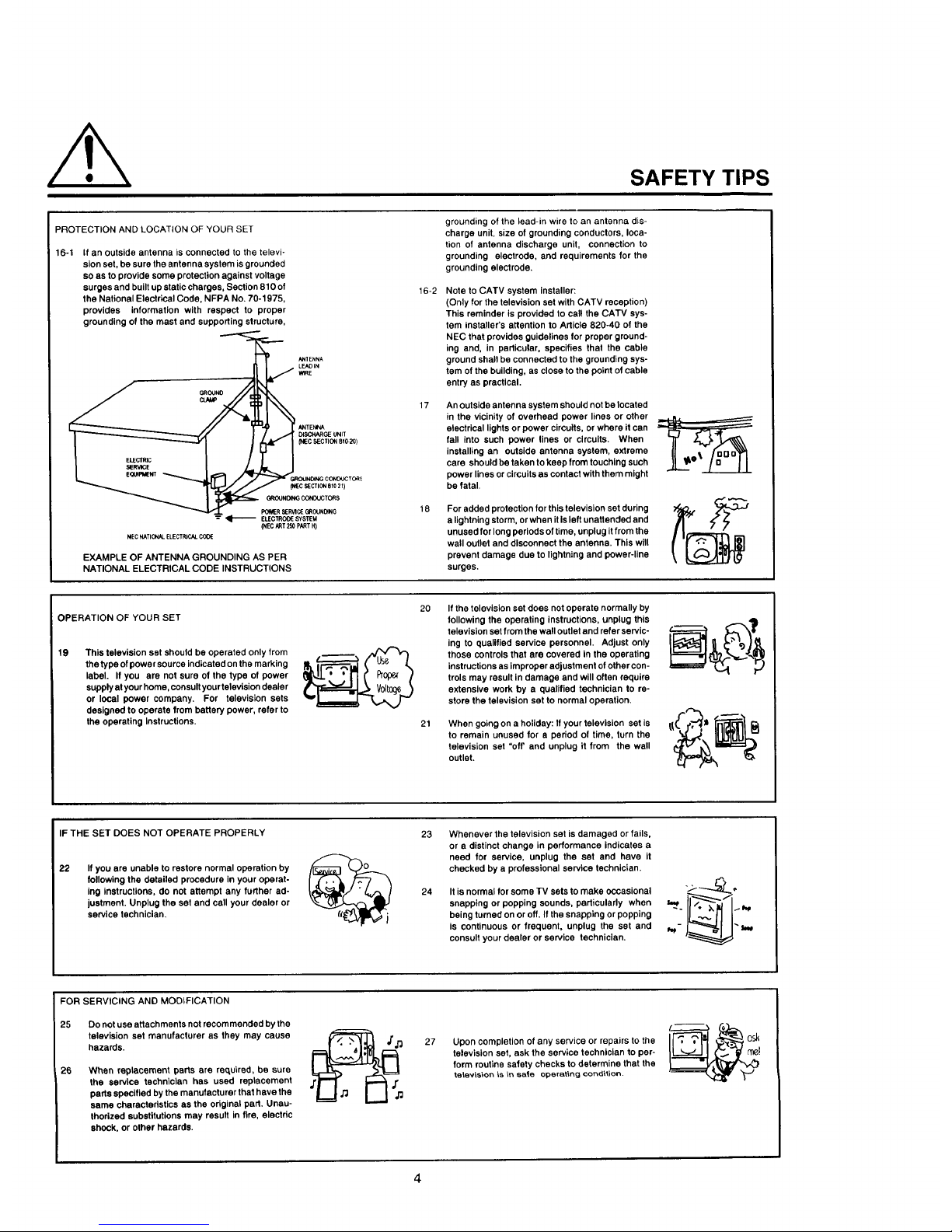
PROTECTION AND LOCATION OF YOUR SET
16-1 If an outside antenna is connected to the televi-
sion set, be sure the antenna system is grounded
so as to provide some protection against voltage
surges and built up static charges, Section 810 of
the National Electrical Code, NFPA No. 70-1975,
provides information with respect to proper
grounding of the mast and supporting structure,
_,_CHARGE UNIT
(NEC SECTION B f0.20)
POWERS£RVlCEG_OUN_NG
--" _ ELEC'rROOE SYSTEM
(NEC ART 250 pART H)
P#ECNATIONAL ELECTRICAL COOE
EXAMPLE OF ANTENNA GROUNDING AS PER
NATIONAL ELECTRICAL CODE INSTRUCTIONS
16-2
17
18
grounding of the lead-in wire to an antenna dis-
charge unit, size of grounding conductors, Ioca-
tion of antenna discharge unit, connection to
grounding electrode, and requirements for the
grounding electrode.
Note to CATV system installer:
(Only for the television set with CATV reception)
This reminder is provided to cal! the CATV sys-
tem installer's attention to Article 820-40 of the
NEC that provides guidelines for proper ground-
ing and, in particular, specifies that the cable
ground shall be connected to the grounding sys-
tem of the building, as close to the point of cable
entry as practical.
An Outside antenna system should not be located
in the vicinity of overhead power lines or other
electrical lights or power circuits, or where it can
fal! Into such power lines or circuits. When
installing an outside antenna system, extreme
care should be taken to keep from touching such
power lines or circuits as contact with them might
be fatal.
For added protection for this television set during
a lightning storm, or when it Is left unattended and
unused for long periods of time, unplug itfrom the
wall outlet and disconnect the antenna. This will
prevent damage due to lightning and power-line
surges.
OPERATION OF YOUR SET
19
This television set should be operated only from
the type of power source indicated on the marking
label. If you are not sure of the type of power
supply at your home, consult your television dealer
or local power company. For television sets
designed to operate from battery power, refer to
the operating Instructions.
2O If the television set does not operate normally by
following the operating instructions, unplug this
television set from the wall outlet and refer servic-
ing to qualified service personnel. Adjust only
those controls that are covered in the operating
instructions as improper adjustment of other con-
trols may result in damage and will often require
extensive work by a qualified technician to re-
store the television set to normal operation.
When going on a holiday: If your television set is
to remain unused for a period of time, turn the
television set "off' and unplug it from the wall
outlet.
IF THE SET DOES NOT OPERATE PROPERLY
22
Ifyou are unable to restore normal operation by
following the detailed procedure in your operat-
ing instructions, do not attempt any further ad-
justment. Unplug the set and call your dealer or
service technician,
2324Whenever the television set is damaged or fails,
or a distinct change in performance indicates a
need for service, unplug the set and have it
checked by a professional service technician.
It is normal for some TV sets to make occasional
snapping or popping sounds, particularly when
being turned on or off. If the snapping or popping
is continuous or frequent, unplug the set and
consult your dealer or service technician.
FOR SERVICING AND MODIFICATION
25 Do not use attachments not recom mended by the
television set manufacturer as they may cause
hazards.
26
When replacement parts are recLuired, be sure
the service technician has used replacement
parts specified by the manufacturer that have the
same characteristics as the original part. Unau-
thorized substitutions may result in fire, electric
shock, or other hazards.
27 Upon completion of any service or repairs to the
television set, ask the service technician to per-
form routine safety checks to determine that the
television is in sate operating condV_ion.
Page 5

PICTURE CAUTIONS
WARNING
Continuous On-Screen displays such as
video games, stock market quotations,
computer generated graphics, and other
fixed (non-moving) patterns can cause per-
manent damage to Color Television receiv-
ers. Such "PATTERN BURNS" constitute
misuse and are NOT COVERED by your
Hitachi Factory Warranty.
When using the Picture-in-Picture function, the sub-picture should not be left permanently
in one corner of the screen or a "pattern burn" may develop over a long period of time.
This Color Television receiver was intended mainly for the private viewing of programs
broadcast by TV stations and cable companies and programs from other video sources.
Public viewing may require prior authorization from the broadcaster or owner of the video
program.
Page 6

ACCESSORIES
Check to make sure you have the following accessories before disposing of the packing material.
For information regarding how to obtain these accessories, please call TOLL FREE 1-800-448-2244 for your nearest
HITACHI Authorized Parts Distributor inthe continental United States. For Alaska and Hawaii, please contact you nearest
HITACHI Regional office.
PART NAME
CLU-851GR
REMOTE TRANSMITTER
27UX5B
CLU-692GR
REMOTE TRANSMITTER
27CX4B
CLU-691GR
REMOTE TRANSMITTER
PART NO. ILLUSTRATION
2573972
2573922
_ =_=,
=,,.=,=.==_wl
| re iv ii ||
Q @Q--I
Q_® I
(DdDQ I
m
2573921
r=_=-r_ I
==-=m=tI
(D®® I
®Q® I
®QQ I
o® I
27CX3B
TELEVISION STAND
SP292B (Black Color)
(Not included, order separately)
TELEVISION STAND
SP291G (Grey Color)
(Not included, order separately)
H410253 (Black)
H410252 (Grey)
CLU-851GR
l!
m-==m I
®®® I
®®® I
®®® I
®_® I
;N
CLU-692GR CLU-691GR
I
!
I
CAUTION: The television stand Model SP291G and Model SP292B are designed for use only with HITACHI
TV models 27UX5B, 27CX4B and 27CX3B. Use with other television equipment may result in
instability, causing possible injury.
Page 7

REMOTE CONTROL BATTERY INSTALLATION AND
REPLACEMENT
1.
2.
Open the battery cover of the remote transmitter by
pushing the notched part of the cover with your
fingers.
Insert new "AA" size (SUM-3) batteries or equiva-
lent for the Genius Remote. When replacing old
batteries, push them towards the springs and lift
them out.
BOTTOM
3. Match the (+) and (-) marks in the battery compart-
ment.
4. Replace the cover.
4 REAR
CAUTIONS
1. If your television set is to remain unused for a long period of time, for instance, when you go on a vacation,
unplug the television set from the wall outlet.
2. Do not subject the Remote Transmitter to shocks such as dropping it on the floor, etc. Precision parts may be
damaged.
3. Do not allow the Remote Transmitter to become wet and avoid placing it in areas of high humidity. Don't leave
it on or near a heater. Excess heat or moisture may cause the unit to cease operation.
4. Ifthe batteries become exhausted, Remote Control operation may become erratic or stop altogether. Replace
the old batteries with fresh "AA" (SUM-3) types.
NOTES
1. When the power button is set to OFF, the OFF TIMER is released.
2. The CHANNEL NO. indication, VOLUME indication and OFF TIMER indication are not displayed simulta-
neously.
3. To operate your TV, point the Remote Transmitter at the remote sensor of the TV.
Page 8

HOW TO SET UP YOUR NEW HITACHI COLOR TV
ANTENNA
Unless your TV is connected to a cable TV system or to a centralized antenna system, a good outdoor color TV antenna
=srecommended for the best performance. However, if you are located in an exceptionally good signal area that is free
from interference and multiple image ghosts, an indoor antenna may be sufficient.
LOCATION
Select an area where sunlight or bright indoor illumination will not fall directly on the picture screen. Also, be sure that
the location selected allows a free flow of air to and from the cover of the set.
To avoid cabinet warping, cabinet color changes, and increased chance of set failure, do not place the TV where
temperatures can become excessively hot. For example, in direct sunlight or near a heating appliance, etc.
VIEWING
The major benefit of the HITACHI Color Television is its
viewing screen. To see this screen at its best, test various
locations in the room to find the best spot for viewing. The
drawings give several suggestions.
The best picture is seen by sittingdirectly in front of the TV
and about 3 to 6 feet from the screen.
During daylight hours, reflections from outside light may
appear on the screen. If so, drapes or screens can be
used to reduce the reflection or the TV can be located in
a different section of the room.
If the TV's audio output will be connected to a Hi-Fi
system's external speakers, the best audio performance
will be obtained by placing the speakers equidistant from
each side of the receiver cabinet and as close as possible
to the height of the picture screen center. For best stereo
separation, place the external speakers at least 4 feet
from the side of the TV. Place the surround speakers to
the side or behind the viewing area. Differences in room
sizes and acoustical environments will require some ex-
perimentation with speaker placement for best perfor-
mance.
BEST t
4' MINIMUM I::: L_I
I ,,,=s..o"izo.'r..
'Ill,! ;
-f- F .!.1VIEWINGANGLE
I _,, CAUTION:
I
The magnetic field of external speakers may cause the TV picture to distort if the speakers are
placed too close to the television. Move the speakers away from the "IV until there is no picture
distortion.
Page 9

HOOK-UP CABLES AND CONNECTORS
Most audio/video connections between components can be made with shielded video and audio cables that have phono
connectors. For best performance, video cables should use 75-ohm coaxial shielded wire. Cables can be purchased
from most stores that sell audio/video products. Below are illustrations and names of common connectors.
Before purchasing anycables, be sure of the output and input connector types required by the various components. Also,
make sure the cables are the correct length.
300-OHM TWIN LEAD CONNECTOR
This outdoor antenna cable must be connected to an
antenna adaptor (300-Ohm to 75-Ohm).
"F" TYPE 75-OHM COAXIAL ANTENNA CONNECTOR
For connecting RF signals (antenna or cable TV) to the
antenna jack on the television.
©
PHONO CONNECTOR
Used on all standard video and audio cables which con-
nect to inputs and outputs located on the Television's front
and rear jack panels.
S-VIDEO (SUPER VIDEO) CONNECTOR
This connector is used on camcorders, VCR's, and laser
disc players with an S-Video feature in place of the
standard video cable to produce a high-quality picture.
ANTENNA CONNECTIONS
These sets are equipped with one VHF/UHF antenna terminal. The VHF/UHF terminal can be used for normal TV, cable
TV (CAW), a TV game, etc.
1. VHF (75 Ohm) antenna/CATV
When using a 75 ohmcoaxial cable system, disconnect
theVHF adaptorfrom the VHF 75 ohm receptacleand
connectthe outdoorantennaor CAIV cable to a VHF
75 ohm receptacle.
To Outdoor Antenna or CATV Cable
VHF/UHF
t _'_ U (disconnect)
, Ohm II VHFAdap'°'
Coaxial C_I_ _ _
2. VHF (300 Ohm) antenna/UHF antenna
When using a 300 ohm twin lead from an outdoor
antenna, disconnect the (VHF or UHF) indoor antenna
leads from screws of the (VHF or UHF) adaptor, and
connect outdoor (VHF or UHF) antenna leads to these
screws of the (VHF or UHF) adaptor.
To Outdoor VHF
VHF/UHF t or UHF Antenna
U (connect)
_III_H F Adapter
3. When both VHF and UHF antennas are
connected
Attach an optional ANT. MIXER to the TV antenna
terminal, and connect the cables to the ANT.MIXER.
[Rearof TVset] VHF/UHF
1_ To outdoor
To UHFAntenna VHFAntenna
t
Antennamixel__'}'_ 4".J
Notes:
1. If an outdoor antenna/CATV is to be used, discon-
2,
3,
nect the indoor antenna. Do not leave both the
indoor and outdoor antennas/CATV connected at
the same time, since ghosting and poor reception
may result.
Consult your dealer or service store for the ANT.
MIXER and (VHF or UHF) adaptor.
The special converter (decoder) will be supplied by
the cable company.
Page 10
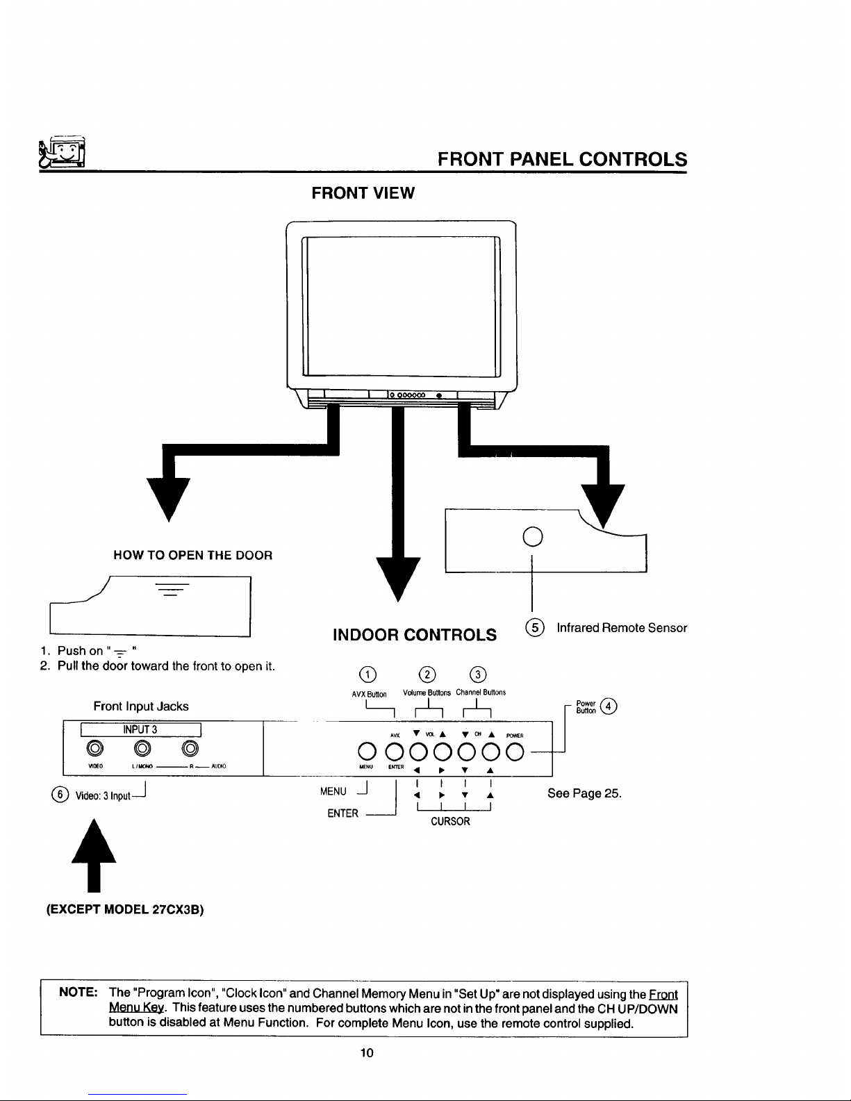
FRONT VIEW
FRONT PANEL CONTROLS
HOW TO OPEN THE DOOR
iJ
1. Push on "--=- "
2. Pull the door toward the front to open it.
Front Input Jacks
I INPUT3 I
© © @
_IOEO LII/O_O -- R -- AUDIO
® V,deo:3,np.t-J
INDOOR CONTROLS
MENU
@ ® ®
AVXButton Volume Buttons Channel Buttons
O000000--
MENU e_r_R • I_ • •
J I I I I
J • _ • •
I I I I
CURSOR
ENTER --
(EXCEPT MODEL 270X3B)
O
®
Infrared Remote Sensor
Power @
See Page 25.
NOTE: The "Program Icon", "Clock Icon" and Channel Memory Menu in "Set Up" are not displayed using the Front
Menu Key. This feature uses the numbered buttons which are not in the front panel and the CH UP/DOWN
button is disabled at Menu Function. For complete Menu Icon, use the remote control supplied.
10
Page 11

FRONT PANEL CONTROLS
AVX(Audio/Video) selector
Press this button to select the current antenna source, or VIDEO: 1,2 or 3. Your selection is shown in the top right
corner of the screen. Model 27CX3B does not have VIDEO: 3.
Q VOLUME level
Press these buttons for your desired sound level. The volume level will be displayed on the IV screen.
Q CHANNEL selector
Press these buttons until the desired channel appears in the top right corner of the TV screen.
G POWER button
Press this button to turntheTV ON or OFF.
NOTE: Your HITACHI TV will appear to be turned"OFF" If there isno video input when VIDEO: 1,2, or 3 is selected.
Press AVX until it returns to the same VIDEO: 1,2 or 3, if not Power is "OFF".
Q REMOTE CONTROL sensor
Point your Genius Remote at this area when selecting channels, adjusting volume, etc.
Q FRONT INPUT JACKS (for VIDEO: 3)
Usetheseaudio/video jacksfora "quick" hook-upfrom a camcorder or VCR to instantlyview your favoriteshowor
new recording.(Pressthe AVXbuttonuntilVIDEO: 3 appearsinthe toprightcornerofthe TV screen.)
11
Page 12
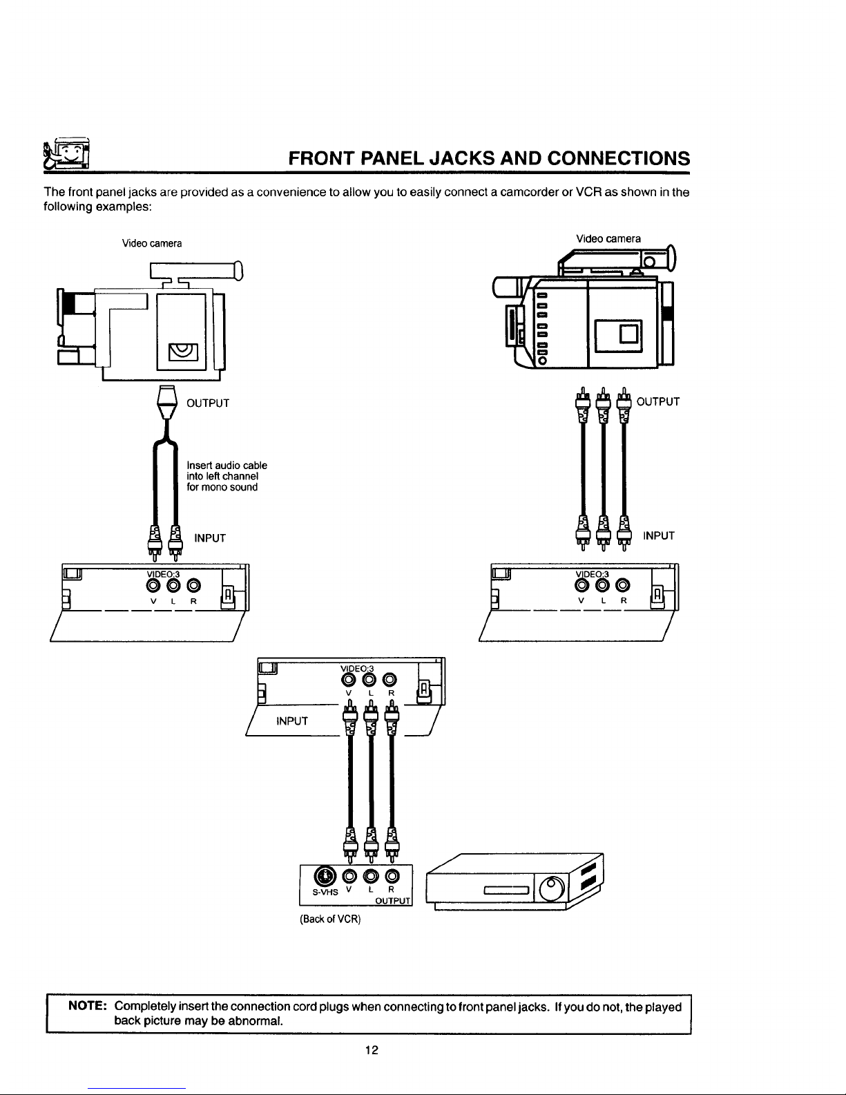
FRONT PANEL JACKS AND CONNECTIONS
The front panel jacks are provided as a convenience to allow you to easily connect a camcorder or VCR as shown in the
following examples:
Videocamera Videocamera
L 0
_ It/" t
OUTPUT OUTPUT
Insertaudiocable
intoleft channel
for monosound
INPUT INPUT
000
V L R V L
/ /
YlNPUT
v L
I s.v.s 0 0
@? .
OUTPUT
(Backof VCR)
NOTE:
Completely insert the connection cord plugs when connecting to front panel jacks. Ifyou do not, the played I
back picture may be abnormal.
I
12
Page 13
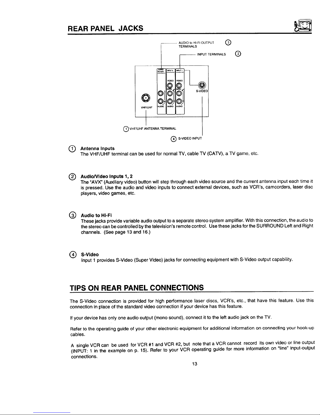
REAR PANEL JACKS
O
VHF/UHF
-- AUDIO to HI-FI OUTPUT
TERMINALS
®
--- INPUT TERMINALS
¢11©_@!/Oi@L= s.v_Eo
iAuo_oI*uolo Auto ]
®
®
Q VHF/UHF ANTENNA TERMINAL
Q S-VIDEO INPUT
Antenna Inputs
The VHF/UHF terminal can be used for normal TV, cable TV (CATV), a TV game, etc.
®
AudioNideo Inputs 1, 2
The "AVX" (Auxiliary video)button willstepthrougheach videosource and the current antenna input each time it
is pressed.Use the audioand videoinputstoconnectexternaldevices,suchas VCR's,camcorders,laserdisc
players,video games,etc.
@
Audio to HI-Fi
These jacks provide variable audio output to a separate stereo system amplifier. With this connection, the audio to
the stereo can be controlled by the television's remote control. Use these jacks for the SURROUND Left and Right
channels. (See page 13 and 16.)
Q S-Video
Input 1 provides S-Video (Super Video) jacks for connecting equipment with S-Video output capability.
TIPS ON REAR PANEL CONNECTIONS
The S-Video connection is provided for high performance laser discs, VCR's, etc., that have this feature. Use this
connection in place of the standard video connection if your device has this feature.
If your device has only one audio output (mono sound), connect it to the left audio jack on the TV.
Refer to the operating guide of your other electronic equipment for additional information on connecting your hook-up
cables.
A single VCR can be used for VCR #1 and VCR #2, but note that a VCR cannot record its own video or line output
(INPUT: 1 in the example on p. 15). Refer to your VCR operating guide for more information on "line" input-output
connections.
13
Page 14
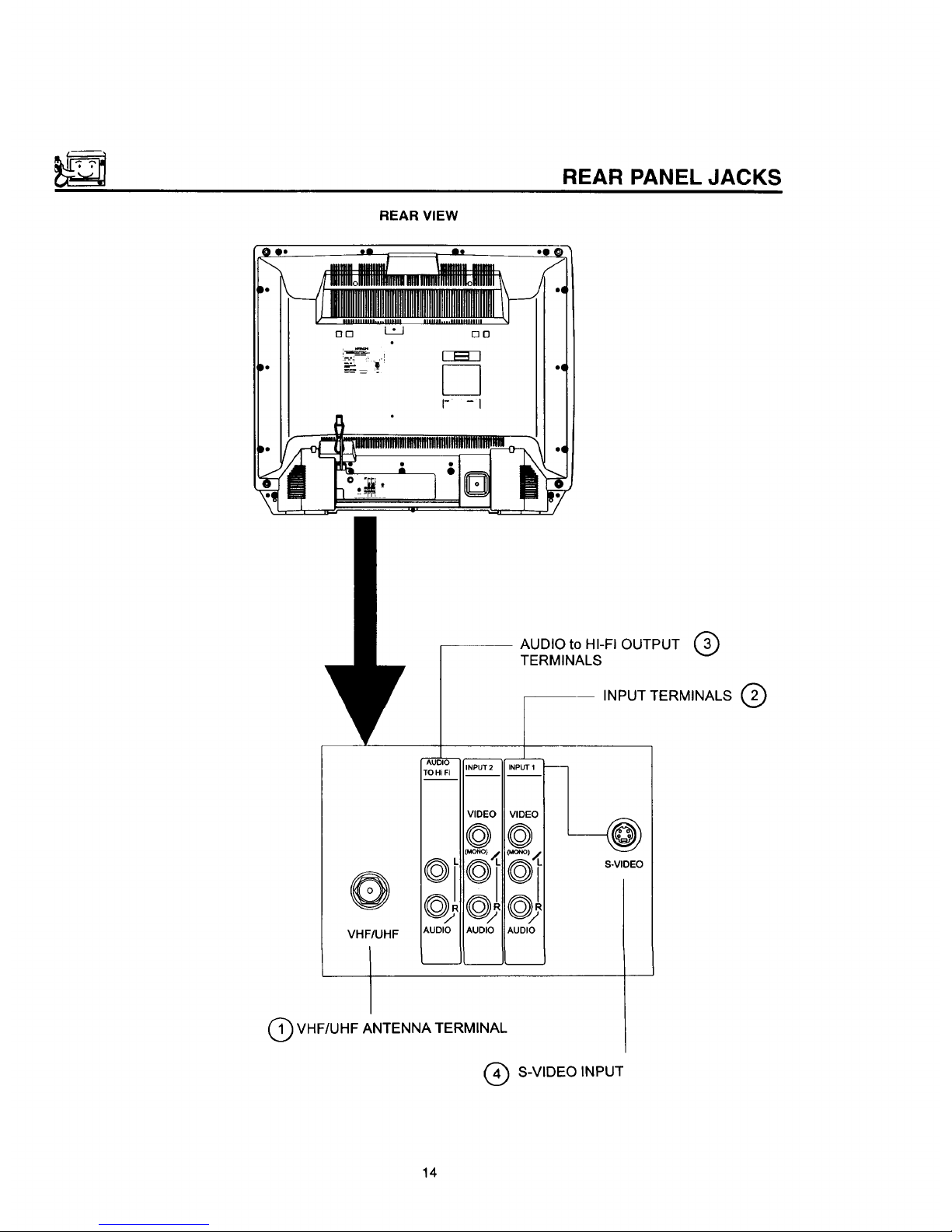
REAR VIEW
REAR PANEL JACKS
'I
@
AUDIO to HI-FI OUTPUT (3)
TERMINALS
VHF/UHF
I
_k_
AUDIO
INPUT2 INPUT 1 --
TO Hi FI
VIDEO VIDEO
@@
AUDIO AUDIO AUDIO
I
INPUT TERMINALS @
-@
S-VIDEO
VHF/UHF ANTENNA TERMINAL
S-VIDEO INPUT
14
Page 15

REAR PANEL CONNECTIONS
__ Outside antenna or
cable TV coaxial cable
R _ 2-way signal splitter
O
O
O
O
=,====_ O
DD_O O
F_ F-_-30 0 0
Illlll IIIIII 0
D
r--------n
StereoSystemAmplifier
Laserdisc player, VCR, IF-
camcorder, etc. \_I_I_IL
I,,_ s.;Hs v ,. R I
_" _"_ "-OUTPUT I
Optional, see tips
on page 13.
Typical full feature set-up. Follow connections that pertain to your personal entertainment system.
15
Page 16

CONNECTING EXTERNAL AUDIO AMPLIFIER
EXTERNAL CONNECTIONS
To control the audio level of an external audio amplifier with the Remote Transmitter, connect the system as shown below
in Fig. 1.
(Rear of Set)
Audio To HI-FI Terminal
EX'rERNAL AUDIO AMPLIFIER EXTERNAL
SPEAKER SPEAKER
FIG. 1
NOTE: To prevent damage to the speaker and distorted sound, set the volume control of the audio amplifier lower
and adjust the sound level using the volume control on the Remote Transmitter of the TV set.
16
Page 17

CONNECTING EXTERNAL VIDEO SOURCES
The exact arrangement you use to connect the Video Cassette Recorder, Video Disc Player and Video Camera to your
TV set is dependent on the model and features of each component. Check the Owner's Manual of each component for
the location of its video and audio inputs and outputs. The following connection diagrams are offered as suggestions.
However, you may need to modify them to accommodate your particular assortment of components and features. For
best performance, video and audio cables should be made from coaxial shielded wire.
BEFORE OPERATING EXTERNAL VIDEO SOURCE
The input mode is changed every time the AVX button is pressed as shown below. Connect EXTERNAL source to the
INPUT terminal, then press the AVX button as necessary to view the input source.
INPUT MODE SELECTION ORDER
(Antenna) (Input)
"L I v,o o
F
NOTE: When TV is set to "VIDEO" and a video signal is not received from VIDEO INPUT JACK on the jack panel
of the TV (i.e., VCRNideo Disc Player, etc. is not connected or the video device is OFF), the screen will
be grey-blue.
CONNECTING MONAURAL AUDIO VCR OR VIDEO DISC PLAYER
1.
2.
3.
Connect the cable from the VIDEO OUT of the VCR or Video Disc Player to the INPUT (VIDEO) jack on the TV set.
(Fig. 1)
Connect the cable from the AUDIO OUT of the VCR or Video Disc Player to the INPUT (MONO)/L(AUDIO) jack.
(Fig. 1)
Press the AVX button to view the program from the VCR of Video Disc Player. The video mode "VIDEO" disappears
automatically after approx. 8 seconds.
4. Press the AVX button to return to the previous channel.
5. See Below.
Video Cassette Recorder
"IV INPUT
TERMINAL
INPUT I
VIDEO I
@l
(MONO) I
f _
VIDEO OUT AUDIO OUT
AUDIO I
FIG. 1
17
Page 18

CONNECTING EXTERNAL VIDEO SOURCES
CONNECTING STEREO VCR OR STEREO VIDEO DISC PLAYER
1°
2.
3,
4.
Connect the cable from the VIDEO OUT of the VCR or Video Disc Player to the "INPUT (VIDEO)" jack on the TV
set. (Fig. 1)
Connect the cable from the AUDIO OUT "R" of the VCR or Video Disc Player to the "INPUT(AUDIO/R)" jack.
(Fig. 1)
Connect the cable from the AUDIO OUT "L" of the VCR or Video Disc Player to the "INPUT(AUDIO/L)" jack.
(Fig. 1)
5. Press the AVX button to return tothe previous channel.
Press the AVX button to view the program from the VCR or Video Disc Player. The video mode "VIDEO" disappears
automatically after approx. 8 seconds.
Video Cassette Recorder
TV INPUT
TERMINAL
INPUT
VIDEO
MONO_
@"
AUDIO
!, ,0,
VIDEO OUT AUDIO OUT
L R
FIG. 1
NOTE:
I"V INPUT
TERMINAL
OUTPUT
BACK OF VCR
1
HITACHI MODEL VT-S751A
or similar model
Completely insert the connection cord plugs when connecting to REAR panel jacks.
played back picture may be abnormal.
If you do not the
If you have an S-VHS VCR, use the S INPUT cable in place of the standard video cable.
18
Page 19

AUDIO SYSTEM SET-UP
Match the numbers below to the diagram for speaker placement and refer to the table for the different surround sound
requirements. (,See page 53 for SURROUND functions.)
The television's internal speakers.
connected to audio Use the "Audio to Hi-Fi" the TV.
These
speakers
are
a
separate amplifier. output
on
SURROUND REQUIRED OPTIONAL EFFECT
FEATURE CONNECTION CONNECTION
OFF @ @ Receive Mono and Stereo Sound.
SIMULATE @ @
MUSIC
MOVIE
®®
19
AtMonoInput,soundis changedmoreloudly
At stereo Input, sound of music is changed more
loudly, Surround Channel added to left and right
Audio Amplifier speakers.
Movie Theater Reproduction, Surround Channel
added to left and right audio amplifier speakers.
Page 20

S
THE GENIUS REMOTE CONTROL (CLU-851GR)
(MODEL 27UX5B)
In addition to controlling all the functions on your HITACHI
Color TV, the new Genius Remote is designed to operate
different types of VCR's and different types of CATV
(Cable TV) converters with one touch. Basic operation
keys are grouped together in one area. All other controls
are separated from them and arranged in MULTI-PAGE
sections, with a display that can be switched to cover any
of the four pages. Functions are arranged and properly
categorized into windows, making operation simple when
multiple functions are to be controlled.
To operate your TV, point the Genius Remote at the remote sensor of the TV.
To operate your VCR, point the remote at the remote sensor of the VCR.
@
...
E
I
I
I
i
©
POWER
lo _---- @
READY LEARN
r ° o ° -,-L-,.14ul_........ "--'--_ 3 )L....l.ajmaL_ ........
-_°r-°°,
i
i
i i + i i
.....MF_ol;:;:2:................................
CURSOR
ENTERI|<,,J I I I.)'JJ c_wO
+
@@+
L,oml
I
i
G)®J
®,...@...j
®o
(Z)
Q
.... °°
A_
0
HITACHI
GENIUS REMOTE
CLU-851GR
®
,@ LIGHT button
When you are in a dark room, press this button on
the side of the remote to light up the buttons shown
in (_. The light will stay on for about 8 seconds if
no button is pressed. The buttons will not appear to
light if the room is too bright.
READY indicator light
Refer to Page 34.
SEND/LEARN indicator light
Refer to page 34.
LEARN/USE select switch
(Located on rear side of remote control)
IIFmll
LEARNJ LUSE
LEARN ........ Enters the Learning mode.
(Refer to page 34.)
USE ............ Set for normal use.
MULTI-PAGE select switch
This selectsthe button layoutof the multi-page
sectionofthe remotecontrol.
MULTI--PAGE buttons
These buttons change functions as shown on
page 21.
20
Page 21

MULTI-PAGE WINDOWS
POWER READY LEARN
!1P,NPI IEXCHNGII SHIFTI IFREEZEI!
RECAL !
mL0,,,P,0,
CURSOR
MENU
_0
_w 0
_0
SELECT
SWITCH
3"
POWER READY LEARN
!lTv_.ll II II 0 Ii
tl "_'=II =" It ='_'11 n I!
!1 DO II II I ISELEOTII
II]P........
MENU
S
CURSOR
TvO
vcR •
caw O
USER O
SELECT
SWITCH
When "-rv" is set
When "VCR" is set
POWER READY LEARN
!1 II II II II
!l i i II i ISELEOTII
MENU
CURSOR
_O
vc_ O
u_R O
SELECT
SWITCH
"€
POWER READY LEARN
!I A II B II c II D II
!I E II F II G II H II
!I ' II J II K II L II
IILT,P,o,
CURSOR
MENU
VCR 0
caw 0
USER •
__SELECT
SWITCH
When "CATV" is set When "USER" is set
21
Page 22

THE GENIUS REMOTE CONTROL (CLU-692GR)
with P-in-P (MODEL 270X4B)
In addition to controlling all the functions on your HITACHI
Color TV, the Genius Remote Control is designed to
operate different types of VCR's (Also Abbreviated VTR)
and different types of CATV converters (cable boxes) with
one touch. Basic operating buttons are grouped together
in one area. All other controls are separated from them
and arranged in MULTI-PAGE sections, with a display
that can be switched to cover any of the three pages.
Functions are arranged and properly categorized into
windows. Making operation simple even when multiple
functions are to be controlled.
I NOTE: Precoded buttons (@ below) will control HITACHI TV only when the MULTI-PAGE SELECT SWITCH
(@ below) is set to "TV" mode.
To operate your TV, point the Genius Remote at the remote sensor of the TV.
To operate you VCR, point the remote at the remote sensor of the VCR.
To operate your cable box, point the remote at the remote sensor of the cable box.
rv
= V'rR
MENUICAT_ l
I
HITACHI 1
GENIUS REMOTE
CLU-692GR
\
®
®
®
POWER "iV
VTR
MENU/CATV,
lJ11:::,;...........
V'rR,
i MENUICATV,
{(ME.ulI • I IE_rE.I)
II • I P-_c_
'!!1k%:;..........
l
®
@
®
®
®
®
®
MULTI-PAGE SELECT SWITCH
Slide the switch in the direction of the arrow to select
the MULTI-PAGE mode.
Button layout when "TV" is selected.
The P-IN-P, SHIFT, EXCHNG and FREEZE buttons.
Button layout for "VCR."
(Power button turns the VCR ON or OFF.)
Button layout for "MENU/CATV."
(Power button turns cable box ON or OFF.)
See pages 31, 32, 33.
TV EXCLUSIVE BUTTONS
These will always control the TV even when the
Multi-Page select switch is in the VCR or MENU/
CATV position.
PRECODED BUI-FONS
These buttons will control a VCR or a cable box
when the Multi-Page select switch is in the VCR or
MENU/CATV position.
LIGHT BUTTON
When you are in a dark room, press this button on to
light up the Channel Keys, Volume, and the Up and
Down Keys. The light will stay ON for about 8
seconds if no button is pressed. The buttons will not
appear to light if the room is too bright.
22
Page 23

THE GENIUS REMOTE CONTROL (CLU-691GR)
without P-in-P (MODEL 270X3B)
In addition to controlling all the functions on your HITACHI
Color TV, the Genius Remote Control is designed to
operate different types of VCR's (Also Abbreviated VTR)
and different types of CATV converters (cable boxes) with
one touch. Basic operating buttons are grouped together
in one area. All other controls are separated from them
and arranged in MULTI-PAGE sections, with a display
that can be switched to cover any of the three pages.
Functions are arranged and properly categorized into
windows. Making operation simple even when multiple
functions are to be controlled.
To operate your TV, point the Genius Remote at the remote sensor of the TV.
To operate you VCR, point the remote at the remote sensor of the VCR.
To operate your cable box, point the remote at the remote sensor of the cable box.
......... VTR,
M ENU/CA'TV,
-I]IIZZ_:...........
®®®
®®®
®®®
..®...Q...@....
if......_
..
.Q
HITACHI
GENIUS REMOTE
CLU-691GR
T
®
®
®
®
°_°'l
POWER "IV
VTR • i
MENU/CATV • !
II_=l';ii_;iSi_
'mi:::;:............
POWER i W
i _R
L...M.E.NU!.Ce..W."
--MP.....
®
®
®
®
®
MULTI-PAGE SELECT SWITCH
Slide the switch in the direction of the arrow to select
the MULTI-PAGE mode.
Button layout when "TV" is selected.
®
Button layout for "VCR."
(Power button turns the VCR ON or OFF.)
Button layout for "MENU/CATV."
(Power button turns cable box ON or OFF.)
See pages 31, 32, 33.
TV EXCLUSIVE BUTTONS
These will always control the TV even when the
Multi-Page select switch is in the VCR or MENU/
CATV position.
PRECODED BUTTONS
These buttons will control a VCR or a cable box
when the Multi-Page select switch is in the VCR or
MENU/CATV position.
LIGHT BUTTON
When you are in a dark room, press this button on to
light up the Channel Keys, Volume, and theUp and
Down Keys. The light will stay ON for about 8
seconds if no button is pressed. The buttons will not
appear to light if the room is too bright.
23
Page 24

_"_' HOW TO USE THE GENIUS REMOTE TO CONTROL YOUR TV
Detailed explanation of the circled numbers is on the following pages.
Q-
l I;'.....i I Lslc_
@
@-
Q--
't"
POWER READY LEARN
IP_NP1IEXCHNGII SH,FT1IFREEZ4
I II II II I
IIlP.........
............. _3_ ...... ;
I _NU
, ,.,,.g<:ll '-' I1>_=
:_kFI _ I'J: =_0
i N L1 ....... • V ,
i '-'::::::::=-::',,"
!O O ®i ,o..
OOOl
Lo ool
HITACHI
GENIUS REMOTE
CLU-851GR
"O _ O
POWER "iV
VTR
MENUICA13/
[_" --e
mP....... i @
Af LIGHT
HITACHI _
GENIUS REMOTE
CLU-692GR
®
POWER TV •
V'TR•
MENUICAI3/i
ii_;;;ff:f_;_il
m p MuL_p_
--G
rO " O
POWER 3_/
'_fR
MENUICATM
r..........................
mP..... ' O
?
HITACHI I
®
POWER TV .
Vl"R ,
MENU/CAW•
--0
24
Page 25

HOW TO USE THE GENIUS REMOTE TO CONTROL YOUR TV
® POWER button
Press this button to turn the TV set ON or OFF. If
an automatic message is set, it will be displayed
when the TV is first turned ON. (See page 49.)
@
RECALL button
When you want to check the channel being re-
ceived, or if it has a stereo (ST) or second audio
program (SAP), press the RECALL button.
You can also check the time, and ifthe ON TIME
or OFF TIME has been set. (See page 48.)
Audioselected
CHANNEL I /
CAPTION _ / /
, ,.Ews STE_E0 3_'[1_
ST/SA i_..
AUTOMATIQ.___ II
MESSAGE " "GOOD MORNING' II
t_l::l: TII_A_ R _ "ON 7:00 AM I"
v...,,.,_ J rOFF 9:00 PM 10:15
ON TIMER I I"'"" I J
Channel and
Antenna Source
Audio broadcast
TIME
If a video input is used:
,/
VIDEO:I _,
(S-IN)
Video Input
When an S-Video
input is connected
0--
@
®
POWER READY LEARN
I PINP EXCHN SHIFT FREEZ !
II II II I1 I!
I
! REOA'!
mP.u.......
r..............."_i_ ......._
! MENU _ I
!(_----_//II^I l_,'_i_"
i,_E"_'%_(_l'-' I_i_;:o
I _ usE.O
' I I I
I I I I
CHANNEL_ t ........ -' VOLUME r_
.....,
i®®®i
i@ '
@@
........ ,
i
o ..@.......'.o.'..i
HITACHI
GENIUS REMOTE
CLU-851GR
)--@
You can also use the RECALL button to quickly clear
many of the other On-Screen displays.
25
Page 26

®
HOW TO USE THE GENIUS REMOTE TO CONTROL YOUR TV
MENU, ENTER, and CURSOR buttons
All the On-Screen display features can be set or adjusted by using these buttons.
The "MENU" button wilt start or exit the On-Screen display.
The "CURSOR" buttons will highlight functions or adjust different features.
These buttons are also used for FAVORITE CHANNELS. (See page 43 .)
The "ENTER" button will set features to your preference.
"CHANNEL SELECT" buttons are used to set the time, channel memory, etc.
®
CHANNEL SELECTOR buttons
Enter two or three numbers toselect channels. Enter a"0" firstfor channels I to 9. Use the "100" button for channels
100 and higher.
Channel selection may also be performed by pressing channel up (• ) or down ( • ).
I NOTE: The TV may not receive some channels if you are not in the correct AIR/CABLE mode. See page 40.
Q AVX button
The AVX (Auxiliary Video) button wilt select between the antenna signal and the three sets of video input jacks each
time the button is pressed.
AVX
VIDEO:I
(S-tN)
AVX AVX
O O
I
VIDEO:3
AVX
O
(Except Model 27CX3B)
VIDEO:2
26
Page 27

HOW TO USE THE GENIUS REMOTE TO CONTROL YOUR TV
Q VOLUME, MUTE buttons
Press the "VOLUME" up ( • ) or down ( • ) button until you obtain the desired sound level.
To turn the sound OFF instantly to answer the telephone, etc., press the "MUTE" button. Press the "MUTE" button
again or press the "VOLUME" up (•) button to restore the sound.
MTV STEREO 28
VOLUME
IIIIHIHIIIIIIIIIIIIII""""""""""""'
f
Louder
>
The word "MUTE" will remain displayed if the CLOSED CAPTION feature is turned OFF.
The word "MUTE" will not be displayed if the CLOSED CAPTION feature is ON.
Waila minute,Ihat'snota spol ,aJnght,who's
heel1eatingchocolaledc_utsinIhe lab?
LAST CHANNEL (LST-CH) button
V
Use this button to select between the last two channels viewed, (Good for watching two sporting events, etc.)
PRME STEREO 28
L_ ST/SA
Q
STEREO 39
Q PICTURE-IN-PICTURE buttons
See separate section on page 28 for a description.
Q LIGHT BUTTON
When you are in a dark room, press this button to light up the volume and channel buttons, The light will stay ON
for about 8 seconds if no buttons is pressed. The buttons will not appear to light if the room is too bright.
27
Page 28

j
PICTURE-IN-PICTURE (P-IN-P) MODELS 27UX5B/27CX4B
The Picture-in-Picture feature is convenient when you want to watch more than one program at the same time.
You can watch a TV program while viewing a VCR program (TV or tape) on video input 1, and vice versa with this feature.
Front or back of TV
t v L R VIDEO IN
00©
®
f...-..---_.-----_
_) _
POWER READY LEARN
P!NP eXCHNG S_,rt _reeze
' J I
I II II II i
-_Li
I I I 1I I I .,_"-LI
CLU-851GR
POWE R TVo
VtRo
I MENUICATV •
CLU-692GR
O -IN-P BUTTON
Press the "P IN P" button and a sub-picture appears in one corner of the screen. Press the button a second time
to remove the sub-picture from the screen. The TV channel will always be either the main picture or the sub-picture.
NEWS = STEREO
Main Picture
NEWS STEREO ;.,
Sub-Picture
EXCHNG (EXCHANGE) BUTTON
If you wish to switch what is being shown on the main picture to the sub-picture, press the "EXCHNG" button.
NEWS STEREO 31
ST/SA!
28
Page 29

PICTURE-IN-PICTURE (P-IN-P)
Q SHIFT BUTTON
To move the sub-picture to another corner, press the "SHIFT" button. The sub-picture moves one step counter-
clockwise every time the "SHIFT" button is pressed.
®
FREEZE BUT-I'ON
If you wish to freeze the sub-picture, press "FREEZE" button. This is convenient when trying to write down the
address for a mail order company, recording statistics for a sporting event, etc. To return to motion, press the button
again.
Q REEZE BUTTON WITHOUT A SUB-PICTURE
Press this button without a sub-picture to freeze the picture you are currently viewing. Press this buttton again or
P IN P to returnto normal viewing. The EXCHNG picture-in-picture function will not work with this FREEZE function.
31
o€
_o.
//_CAUTION: A pattern burn may develop the sub-picture is in the same corner permanently. If the
if left
P-IN-P feature is used frequently, occasionally shift the sub-picture to a different corner.
NOTE:
1. Only sound from the main picture can be heard.
2. P-IN-P will not work with a CHILD LOCK channel as the Main Picture but it will be displayed as a Sub-Picture.
3. The Sub-Picture will not appear while a FAVORITE CHANNEL is being selected. The Sub-Picture will reappear
after the FAVORITE CHANNEL display is gone.
4. When the "P-in-P" button is pressed, the sub-picture will appear inthe same position as previously set.
5. The "FREEZE" function is released when the"EXCHNG" button is pressed.
6. The P-in-P sub-picture only works on VIDEO:I input.
29
Page 30

USING THE GENIUS REMOTE TO CONTROL VCR FUNCTIONS
OPERATING THE PRE-GODED FUNCTION FOR YOUR VCR.
This Genius Remote isdesigned to operate different types of VCRs. You must first program the Genius Remote to match
the remote system in your VCR. (Refer to Table 1 on page 32 or Table 3 on page 33.)
1. Set the MULTI-PAGE select switch to "VCR."
2. Set the USE/LEARN mode select switch on the rear side of the Genius Remote to 'USE." (For CLU-851GR only)
3. Turn ON your VCR.
4. Aim the Genius Remote control at the front of your VCR.
5.
While holding down the SELECT button, press the button that matches your VCR as shown on page 32 or page 33.
Continue to hold down both buttons. The channels of the VCR will begin changing when the correct button is
pressed. When this occurs, the Genius Remote Control is programmed for your VCR. If the VCR channels do not
change after 5 seconds, try a different Genius Remote button.
6. Release both buttons when the VCR starts to change channels. The Genius Remote will now control your VCR.
®
®
NOTES:
1. Ifyour VCR cannot be operatedafter performing
the above procedures,this means that your
VCR's codes have notbeen precodedintothe
GENIUS REMOTE. Please store your VCR
codes in memory by using the USER mode.
(Referto page 34.)
2. The GENIUS REMOTE CONTROL will remem-
berthecodesyouhave programmedinuntilthe
batteriesare removed from the GENIUS RE-
MOTE CONTROL. Afterreplacingthe batteries
repeattheentireprogrammingprocedurestated
above.
3. If you have a play back only VCR (noCH UP/
DOWN function), pleasefollow operatingstep5
describedaboveandthenchecka VCR function
untilyoufindthebuttonthatwillallowtheprecoded
VCR buttons to operate your VCR.
PRECODED VCR BUTTONS
These buttons always transmit the chosen precoded
VCR codes.
SELECT BUTTON
This is for setting up the Genius Remote to transmit
the VCR's remote codes.
EXCLUSIVE TV BUTTONS
These buttons are for operatingthe TV.
Q
POWER READY LEARN
ITWW.II II II 6 I!
HITACHI
GENIUSREMOTE
CLU-851GR
3O
Page 31

USING THE GENIUS REMOTE TO CONTROL CABLE
BOX FUNCTIONS
OPERATING THE PRE-CODED FUNCTION FOR YOUR CABLE BOX.
This Genius Remote isdesigned to operate different types of cable boxes. You must first program the Genius Remote
to match the remote system in your cable box. (Refer to Table 2 on page 32 or Table 4 on page 33.)
1. Set the MULTI-PAGE select switch to"CATV."
2. Set the USE/LEARN mode select switch to "USE." (For CLU-851GR only)
3. Turn ON your cable box.
4. Aim the Genius Remote control at the front of your cable box.
5.
While holding down the SELECT button, press the button that matches our cable box as shown on page 32 or page
33. Continue to hold down both buttons. The channels of the cable box will begin changing when the correct button
is pressed. When this occurs, the Genius Remote Control is programmed for your cable box. If the cable box
channels do not change after 5 seconds, try a different Genius Remote button.
6.
®
®
®
Release both buttons when the cable box starts to change channels. The Genius Remote will now control your cable
box.
o o
POWER READY LEARN
NOTES:
1. If your cable box cannot be operated after per-
forming the above procedures, this means that
your cable box codes have not been precoded
into the GENIUS REMOTE. Please store your
cable box codes in memory by using the USER
mode. (Refer to page 34.)
The GENIUS REMOTE CONTROL will remem-
ber the codes you have programmed in until the
batteries are removed from the GENIUS RE-
MOTE CONTROL. After replacing the batteries,
repeat the entire programming procedure stated
above.
2.
PRECODED FOR CABLE BOX
These buttons always transmit the chosen precoded
CATV codes.
SELECT BUTTON
This is for setting up the cable box's Pre-code.
O-
EXCLUSIVE TV BUTTONS
These buttons are foroperatingthe TV.
I II II II I
I II II I ISELECTI
.................. _01_"
MENU
GENIUSREMOTE
CLU-851GR
J
31
Page 32

S
VCR AND CABLE BOX CODES
TABLE 1. VCR PRECODEDREMOTECONTROLSFORHITACHIGR111 REMOTECLU-851GR.
Press SELECT and this
VCR BRAND button
Audio Dynamics VOLUME •
Canon 6
Citizen 0
Craig VOLUME •
Curtis Mathes 2/6
dbx VOLUME •
Dimensia 2
Emerson 100/ENTER
Fisher VOLUME •
GE 2/6
Goldstar 0
Hitachi 1
Instant Replay 6
JC Penny 1/6/9/VOLUME •
JVC 0/VOLUME •
Kenwood 0/VOLUME •
Magnavox 4/6
Marantz 9/VOLUME •
Press SELECT and this
VCR BRAND button
NEC 9NOLUME •
Panasonic 6
Pentex 1
Philco 4/6
Philips 4/6
Pioneer 1
ProScan 2
Quasar 6
RCA 1/2
Realistic 6/9/CHANNEL •/VOLUME •
Sanyo 9/VOLUME
Scott 7/8
Sears 1/9
Sharp CHANNEL •
Sony 5/MUTE/AVX
Sylvania 4/6
Tashiko 0
Technics 6
Marta 0
Memorex 6/VOLUME •
MGA 7
Minolta 1
Mitsubishi 7
Montgomen j Wards CHANNEL •
Toshiba 1/8
Vector Research VOLUME •
Video Concepts VOLUME •
Wards CHANNEL •
Yamaha 0/VOLUME •
Zenith 3/5
TABLE 2. CABLEBOXPRECODEDREMOTECONTROLSFORHITACHIGR111 REMOTECLU-851GR.
CATV Brand
General Instrument
Hamlin
Jerrold
Magnavox
Panasonic
Philips
Press SELECT and this Press SELECT and this
button CATV Brand button
0/1/2/3 Pioneer 7
4 Regal 4
1/2/3/3 Scientific Atlantic 6
9 Viewstar 9
8 Zenith 5
9
32
Page 33

VCR AND CABLE BOX CODES
TABLE 3. VCR PRECODEDREMOTECONTROLSFORHITACHIGJ111 REMOTECLU-691GR ANDCLU-692GR.
Press SELECT and this
VCR BRAND button
Canon 6
Citizen 0
Curtis Mathes 2/6
Dimensia 2
GE 2/6
Goldstar 0
Hitachi 1
Instant Replay 6
JC Penny 1/6/9
JVC 0
Kenwood 0
Magnavox 4/6
Marantz 9
Press SELECT and this
VCR BRAND button
Pentex 1
Philco 4/6
Philips 4/6
Pioneer 1
ProScan 2
Quasar 6
RCA 1/2
Realistic 6/9/CHANNEL •
Sanyo 9
Scott 7/8
Sears 1/9
Sharp CHANNEL •
Sony 5/VOLUMEANOLUME •
Marta 0
Memorex 6
MGA 7
Minolta 1
Mitsubishi 7
Montgomery Wards CHANNEL •
NEC 9
Panasonic 6
Sylvania 4/6
Tashiko 0
Technics 6
Toshiba 1/8
Wards CHANNEL •
Yamaha 9
Zenith 3/5
TABLE 4. CABLEBOXPRECODEDREMOTECONTROLSFORHITACHIGJ111 REMOTECLU691GR ANDCLU692GR.
Press SELECT and this
CATV Brand button
General Instrument 0/1/2/3/8
Hamlin 4
Jerrold 0/1/2/3/8
Pioneer 7
Press SELECT and this
CATV Brand button
Regal 4
Scientific Atlantic 6
Viewstar 9
,Zenith .5
33
Page 34

USING THE GENIUS REMOTE TO LEARN ADDITIONAL
FUNCTIONS FOR CLU-851GR
The Genius Remote is equipped with a learning function
which allows it to learn additional infrared control codes.
This remote will not only control the television, a VCR, and
a cable box, but also other electronic equipment which
uses an infrared remote transmitter, by learning the
transmitter's codes.
Only infrared remote control codes can be stored in
memory.
BEFORE STARTING THE MEMORY OPERATION
Since the infrared signals sent from the remote transmit-
ter may be reflected by a wall, door, etc., even if the
transmitter is not pointed directly at the device, it may
operate. When storing the remote control codes of an-
other device, turn OFF the power of the device (VCR,
Cable Converter, etc.)
If you do not do this, the device may work unexpectedly.
The power could be turned ON, an important tape could
be erased, the volume could increase too much, etc..
3"
POWER READY LEARN
,, tt c ,,
GENIUSREMOTE
CLU-851GR
!
!
!
®
LEARNABLE BUTTONS
These buttons can "learn" the codes of other remote
control transmitters when the MULTI-PAGE select
switch is set to the "USER" mode.
@
MULTI-PAGE keys (A through L): No codes
have been factory stored to these keys.
Learning buttons other than MULTI-PAGE but-
tons: the codes for the TV have been stored in
memory. However, the remote control codes of
other equipment (cable converter, audio equip-
ment, etc.) can be stored using the learning
function as shown on page 35 and page 36.
EXCLUSIVE BUTTONS
These buttons are for operating the TV.
34
Page 35

USING THE GENIUS REMOTE TO LEARN ADDITIONAL
FUNCTIONS FOR CLU-851GR
STORING OPERATION
®
Set the remote transmitter as shown below.
Put the remote transmitter whichcontains the codes to be stored and the GENIUS REMOTE transmitter to face each
other. (Distance should be 2-4 inches.)
0110
BOB
DBBO
DO00
ODDO
OOffO
G
o!
2 - 4 inches
r-i
°
Remote control to be stored
GENIUS remote control
Set the LEARN/USE mode select switch located on the back of the Genius Remote to the LEARN position.
Set the MULTI-PAGE select switch to "USER" position.
Press of the learnable buttons the Genius in this This button will be used to
ORe on
Remote, ("7" example).
store
the new code. The READY indicator will flash at this time. (The light will remain lit for approximately 15 seconds.
If no other function is performed at this time, the operation is canceled.)
READY LEARN
(flashing) (off)
The Genius Remote is ready to receive an infrared code
from another remote.
Press and hold the button down on the other transmitter which contains the code to be stored, while the READY light
is flashing on the Genius Remote.
Release the button after both the READY and LEARN indicators light and then go OFF.
35
Page 36

USING THE GENIUS REMOTE TO LEARN ADDITIONAL
FUNCTIONS FOR CLU-851GR
READY LEARN
(Goes out) (Lights)
READY LEARN
(Flashing) (Flashing)
When storing has been performed correctly, the LEARN
indicator lights for about 2 seconds.
if the storing was not done correctly, or the codes are too
long to learn, or no more codes can be stored in memory
due to memory overflow, the LEARN indicator and READY
indicator will flash ON and OFF.
®
®
Set the LEARN/USE mode select switch on the back of the Genius Remote to "USE" and check that the button to
which the code is stored operates correctly. If it does not operate correctly, repeat from step 1.
Repeat steps 3 to 5 to store other keys.
To CLEAR THE STORED CODES FROM THE USER MODE.
Set the MULTI-PAGE select switch to the USER mode and LEARN/USE mode select switch to "LEARN." Then, press the
POWER and the MUTE buttons simultaneously for 3 seconds. The "READY" and "LEARN" LEDs will light together. All
MULTI-PAGE KEYS with codes are reset to their initial states.
To remember stored codes, it is convenient to paste the labels (user's label) provided on the buttons for the USER page.
If the correct labels are not provided, it is possible to write these letters on an empty label with a ballpoint pen.
(_ _
POWER READY LEARN
it, ll0 tic ll0 II
II E II F II G II . It
It, IlK JiL tl
mPM0,,, AoE
CURSOR
u_R •
USER'S LABEL
36
Page 37

USING THE REMOTE TO LEARN ADDITIONAL FUNCTIONS
NOTE:
1. To operate your TV, be sure to point the Genius Remote at the remote sensor on the television. To operate other
electronic equipment like a VCR, point the remote at the sensor on the device.
2. Refer to the instruction manual of the VCR for operation on the buttons exclusively for the VCR.
3. Be sure to keep the original remote transmitter even after storing its codes in the Genius Remote Control.
4. If the Genius Remote is left with its batteries removed, the learned codes in its memory are erased and will have
to be reprogrammed into the memory.
5. The Genius Remote Control may not be able to learn certain special remote codes.
CAUTION ON BATTERIES:
1.
2.
3,
The Genius Remote Control is working when the LEARN indicator lights up when a button is pressed.
When you press a button and the learn indicator will not light up or ifthe operation is extremely slow, this is an
indication that the batteries should be replaced.
Even if the batteries seem dead, do not remove them until you have replacement batteries ready to put in. The
codes stored in memory will be erased in a few minutes without power. When replacing batteries, prepare the
new ones first.
3-7
Page 38

EASY GRAPHIC GUIDE
®
®
®
Press MENU on the Remote Control to display the different features on your HITACHI TV. The feature to be selected
will be highlighted in a magenta (purple) color.
Press the CURSOR buttons to highlight a different feature.
Press ENTER on the Remote Control to select a feature.
CURSOR
MENU
I
NOTE: Press the CURSOR buttons first to view FAVORITE CHANNELS (See Page 43.)
I
This part of the screen shows
that selections are available.
This part of the screen shows which
Remote Control buttons to use.
:>
>
PROGRAM VIDEO
RESET
CLOCK
D
AUDIO
,oooeeeoooooooeoeoeeoeeoeooeoooeoooooooootoooo
4Aj_ ENTER MENU
• (SET) (EXIT)
OOOOOO [
NOTE: For CLU-692GR and CLU-691GR, slide MULTI-PAGE select to MENU/CATV mode to work on MENU,
ENTER, and cursor up, down, left and right. Slide to TV mode to use channel • ,V buttons or number
buttons.
38
Page 39

EASY GRAPHIC GUIDE
L,, O,OLEISe'ec'antennaI,UTO
AIR or cable TV. PROGRAM
MEMORY add or erase. I CAPTION
First time setup
forchannel buttons.
I eature to display
dialogue/text.
RESET
Return video and audio adjustments to factory settings.
PROGRAM
I CHANNEL
CAPTION I
I PROGRAMLIST I
I CLOCK
SET
I AUTOMATIC
MESSAGE-1
Label channels I CHILD
PAY1,ABC, etc. I LOCK
Check channel
name, scan,
childlock.
I VOLUME
CORRECTION
Block channel
picture & sound.
Lower volume on
selected channels.
CLOCK
Set before using ON/OFF
timerfeatures. TIMER
I Turn TV ON or OFFone time or daily.
Set for one I AUTOMATIC I Set for one
time or daily. I MESSAGE-2 J time or daily.
VIDEO
Adjust Contrast, Color, Tint, Brightness, Sharpness and White Control.
AUDIO
IPREFERENCE I Adjust balance, IPREFERENCE I Improve s°und
ADJUST bass, and treble. SETTING performance.
SURROUND / Special sound effects.
39
Page 40

SET UP
SET UP
Select SET UP when setting your TV up for the first time. Use the CURSOR UP/DOWN buttons
on the Remote Control to highlight the function desired.
I CURSOR
I_U_°p_MII _IF_r_ENTER
cY
AIPJCABLE
MENU
(EXIT)
AIR/CABLE
AIR
I elect AIR if you are using an indoor or outdoor antenna.
Select CATV if you have cable TV.
Press the CURSOR buttons to highlight the correct AIR/CABLE mode and press MENU to exit.
Your choice will be shown on the display.
Your selection
is shown here
CY
CHANNEL CLOSED
MEMORY J CAPTION
',_11,' ENTER MENU
(SET) (EXIT)
Reception channels for each mode are shown
at the right.
Refer to your cable or TV guide for channel
identification standards.
If certain CATV channels are poor or not pos-
sible in the CATV1 mode, set AIR/CABLE to
CATV2.
AIR
VHF 2 ~ 13ch
UHF 14 - 69ch
RECEPTION BAND
CATV 1 or CATV 2
CATV CHANNEL
VHF2 ~ 13
Mid band A - I
A-5 - A-1
Super band J ~ W
Hyper band
W+I ~W+28
Ultra band
W+29~W+84
Indicated
on the screen
2-13
14 ~ 22
95 ~ 99
23 ~ 36
37 ~ 64
65 - 125
40
Page 41

SET UP
I AUTO
PROGRAM
This feature will automatically store active TV channels in CHANNEL MEMORY. This will allow you
to skip over unused channels when using the CHANNEL UP ( • ) or DOWN ( • ) buttons.
AIR/CABLE AUTO
AIR PROGRAM
CHANNEL
MEMORY I CAPTION I
ENTER MENU
(SET) (EXIT)
AUTOPROGRAM
PRESS ENTER TO BEGIN
MENU
(EXIT)
ENTER
CHANNEL 05
NOW AUTOPROGRAM
IS IN PROGRESS
"-I 1
After Operation
If the MENU button is pressed while the auto programming function is engaged, programming will stop.
See CHANNEL MEMORY to add or erase additional channels.
cY
ENTER MENU
(SET) (EXIT)
CURSOR
"_1 _ I_EN(_
CHANNEL MEMORY
j._NN EL 05
ERASE
NEXT CHANNEL: CH • CH •
MENU
• I). (EXIT)
CURSOR CHANNEL
CHANNEL MEMORY
CHANNEL 05
ADD
NEXT CHANNEL: CH • CH •
MENU
• t) (EXIT)
CHANNEL
MEMORY
Use this function after AUTOPROGRAM to add or erase additional channels by the Remote Control
CHANNEL • ,• buttons. Your Choice will be highlighted in magenta.
I_ I CURSOR
CHANNEL MEMORY CHANNEL MEMORY
._..GI:I_NNEL 05 CHANNEL 05
IADDI ERASE ADD
NEXT CHANNEL: CH • CH • NEXT CHANNEL: CH • CH •
MENU MENU
• I)' (EXIT) • I_ (EXIT)
Add or erase additional channels while still in CHANNEL MEMORY using the CHANN EL •,• buttons or number buttons
and then add or erase using the CURSOR 41, • buttons.
41
Page 42

I CLOSED
CAPTION
SET UP
I Closed captions are the dialogue, narration, and/or sound effects of a television program or home
video which are displayed on the TV screen. Your local TV program guide denotes these programs
as 1"8"_or _.
AIR/CABLE
A R I pROISHAM I
CHANNEL CLOSED
MEMORY CAPT ON
,_ ENTER MENU
(SET) (EXIT)
CURSOR
CLOSED CAP.,_I
DISPLAY :ON
MODE : C.C.
CHANNEL : II!_ 2
4_1_ MENU
(EXIT)
The selected function will be in magenta. Your choice for the function will be in blue.
DISPLAY: ON/OFF is to turn the cc display "ON" or "OFF".
MODE: C.C. (Closed Caption) is for the program you are viewing.
MODE: TEXT is for additional information such as news reports or a TV program guide. This information covers the
entire screen and viewing the TV program is not possible. TEXT may not be available with every r6-61program.
CHANNEL: 1 is used for the primary language (usually English).
CHANNEL: 2 is sometimes used for a second language (may vary by region).
Use the CURSOR • or • to highlight the function to change, press ENTER to change the function, and press MENU
to exit.
C.C. Selected
Text Selected
3
NOTE:
I
The word MUTE will not be displayed if the DISPLAY is "ON". Ifyou do not have sound, make sure MUTE I
is not set, or Int. speaker in on "OFF"
I
42
Page 43

FAVORITE CHANN ELS
The FAVORITE CHANNELS function will allow you to select up to 16 favorite channels by pressing the cursor buttons.
CURSOR CHANNEL
r---_ r--'l r"---i r'"-i
r"--i r---i t---'l r--1
r-"-i f--"l r---i r'-_
ACTION
NEXT CHANNEL:CH • CH •
_&= ENTER MENU
'_P (SET) (EXIT)
ENTER
0 _
m r----1 r---n r---n
r---n r---1 r---1 r--n
r----1 r---1 r----1 r--I
r---1 r---! r--l r---l
ACTION
NEXT CHANNEL:CH • CH •
'_,1_ ENTER MENU
(SET) (EXIT)
Use the CHANNEL • ,V or number buttons to select one of your favorite channels.
Use the CURSOR buttons to select the location (in magenta color) for your favorite channel.
Press ENTER to save the channel location.
Enter channel 00 to erase a favorite channel.
CURSOR
35 50 02 15
37 27 04 [_
21 11 07 99
02 14 31 98
NEXT CHANNEL:CH • CH •
,_ ENTER MENU• (SET) (EXIT)
ENTER
0 )
50 02 15
37 27 04 I----I
21 11 07 99
02 14
CH SET
35
Highlight ACTION and press ENTER to use your favorite channels.
Use the CURSOR buttons to highlight a favorite channel and the TV will automatically tune to the channel.
Highlight CH SET and Press ENTER to add or erase more favorite channels.
43
Page 44

Usetheresettochangeyourpreferredvideoandaudioadjustmentstofactorysettings.
RESET
MENU
0
CURSOR
Factory Settings:
CURSOR
PRESS ENTER TO R_TURN
VIOEO AND AUDIO "_
TO FACTORY SETT_GS
ENTE_ MENU
(SET) (EXIT)
VIDEO AUDIO
ENTER
Contrast: IIIIIIJlIIIIHIIIIIIIH Balance: ,,,,,,,,If,,,,,,,,,
Color: ,,,i,,,ll,,,,,,i,i Bass: iiiimniHIi,JimiHIil
Tint: iiilUlllllllllllltllllllllllll Treble: IIIIIIIIIIIIIIIIIIIIIIIIIIIIIII
Brightness: ,,,,,,,I,,,,,,,, MTS Mode: STEREO
Sharpness: ,,,,,,,,I,,,,,,,,_ Dynamic Bass: OFF
White Control: ON Loudness: OFF
Internal Speakers: ON
Surround: OFF
I NOTE: This RESET Selection will not change your preferred adjustments. To change back to your adjustments,
see VIDEO page 50 or AUDIO page 51.
Yourpreferedvideo
adjustmentsare now set.
44
Page 45

PROGRAM
PROGRAM
This selection contains advanced features which will make TV viewing easier and more enjoyable.
CURSOR
'I_ ENTER MENU
(SET) (EXIT)
CURSOR
[]
CHANNEL CJCRIL_-----]
CAPTION I LOCK 1
PROGRAM I IVOLUME I
L ST I _CORRECTtONI
• ENTER MENU
4VI_ (SET) (EXIT)
CHANNEL
CAPTION
I Use this feature to give to up 30 channels names for each antenna source.
CHANNEL
CAPTION
PROGRAM ] WOLUME
L ST ICORRECT ON
,i_ ENTER MENU
(SET) (EXIT)
ENTER
_ 41
CHANNEL CAPTION
.... (CANCEL)
NEXT CHANNEL: CH& CH •
ENTER MENU
(SET) (EXIT)
CHILL CURSOR
-- _ /'1 r_ r_ENTER
o
PAY1 41
CHANNEL CAPTION
PAY1 (CANCEL)
NEXT CHANNEL:CH& CH•
,_ ENTER MENU
(SET) (EXIT)
Press the CURSOR •, • to select letters.
Press the CURSOR _1, • to change position.
Press ENTER to set the CHANNEL CAPTION and it will appear in the top left corner of the screen.
Press CHANNEL •, • or the number buttons to select and label additional channels.
Press MENU to exit.
The (*) represents a blank space.
Select CANCEL to erase a CHANNEL CAPTION.
IPROGRAM
LIST
I This function allows you to view which channels are labeled inCHANNEL CAPTION (NAME), whichhave been added to CHANNEL MEMORY (SCAN), and which are protected by CHILD LOCK
(LOCK).
CHANNEL CHILD
CAPTION LOCK
PROGRAM IVOLUME
LIST ICORRECT ON
ENTER MENU
(SET) (EXIT)
ENTER
CH NAMESCAN LOCK
01
02 CBS ON
03 VCR ON ON
04 NBC ON --
05 WXYZ ON --
• MENU
• (EXIT)
CH NAMESCAN LOCK
06 JAYB ON --
07 JEKO ON
08 ROLY ON ON
09 TESS ON ON
10
• MENU
• (EXIT)
Press CURSOR • ,• to review more channels.
Press MENU to exit.
45
Page 46

CHILD
LOCK [
This function will block out the picture and sound of the selected channel.
PROGRAM
[]
CHANNELIICNILOI
CAPTION LOCK
PROGRAM IVOLUME
LIST ICORRECT ON
'I_ ENTER MENU
(SET) (EXIT)
ENTER
[_ CHILD LOCK
41
CHILD LOCK IKEY NUMBER
SET ICHANGE t
NEXT CHANNEL: CH • CH •
<_Y NUMBER: 0 - 9
ESN;_R MENU
(EXIT)
The code to set or cancel CHILD LOCK is a three digit key number. The factory preset key number is 000.
[_ CHILD LOCK
41
CHILD LOCK I KEY NUMBER
SET I (_HANGE
NEXT CHANNEL:CH& CH•
KEY NUMBER:0-9
,_ ENTER MENU
(SET) (EXIT)
I_ CHILD LOCK
41
CHILD LOCK
CANCEL I_ MENU
000
NEXT CHANNEL:CH• CH•
KEY NUMBER: 0 - 9
MENU
41 II, (EXIT)
The picture and sound will now be blocked out for this channel. Repeat the same steps to caf_cel the CHILD LOCK.
To change the key number, select key number change. Enter the old number (factory preset 000 for first time use), then
enter a new three digit key number you prefer.
If you forget your key number, use the factory code 777 to erase your key number. This will reset the key
number back to the factory preset 000.
46
Page 47

PROGRAM
I VOLUME
CORRECTION
Use this function to reduce the volume level of up to four TV channels that sound loud compared
to other TV channels.
[]
CHANNEL
CAPT ON
PROGRAM J IVOLUME I
L ST ICORRECTION ]
ENTER MENU
(SET) (EXIT)
LEVEL
100%
100%
100%
100%
NEXT CHANNEL: CH • CH •
,_ ENTER MENU
ISETI tEXIT!
CHANNEL
[_ 22
LEVEL
100%
100%
100%
100%
NEXT CHANNEL: CH • CH •
ENTER MENU
ISET) (EXIT)
Press the CURSOR A, Vto select one of the four volume corrections.
Use the CHANNEL • ,V or number buttons to select a channel.
ENTER
0-_
I_ CH LEVEL
22
ID 100%
100%
100O/o
11)0%
NEXT CHANNEL:CH•CHV
'_b ENTER MENU
(SET) (EXIT)
CURSOR
I_ _CH LEVEL 22 I
100% I
r-'l 1oo% I
NEXT CHANNEL: CH • CH • I
,_t, L ENTER MENUI
y (SET) (EXIT)I
Press ENTER to set the channel.
Press the CURSOR,4, • to adjust volume level.
Press MENU to exit.
NOTE:
1. VOLUME CORRECTION adjustment is for the channel displayed inthe top right corner of the screen.
To adjust a different channel, you must select the channel with the channel or number buttons and
press ENTER.
2. If the channel has been corrected before, use the cursor • ,V to highlight that channel then
use the cursor "4, • to change the level.
3. To erase a channel from the volume correction, select channel 00 and press ENTER.
4. The volume level will change from 50% to 100% in 5% steps.
47
Page 48

CLOCK
Use this feature for all time related lunctions.
CLOCK
I CLOCK
SET
The time must be set before you can use the ON/OFF TIMER or AUTOMATIC MESSAGE.
MENU
o
I
[]
CURSOR I_
/ AT THE FIRST TIME
I ,d•L ENTER MENU
I Y (SET) (EXIT)
[]
CLOCK SET
|-:-- _ PM
HOUR: 01-12
ENTER
(START)
MENU
(EXIT)
Use the NUMBER buttons and CURSOR •, •to set the time.
The AM or PM selected will be highlighted in blue.
ON/OFF
TIMER
I This function will automaticallly turn the TV ON or OFF, one time only or everyday.
|TIMER /
AUTOMATIC AUTOMATIC
M{_SSAGE-1 MESSAGE-2
'4_ ENTER MENU
(START) (EXIT)
ENTER
[]
ON TIME: - -:- - AM PM
OFF TIME: - -:- - AM PM
ON CHANNEL: - -
MODE: OFF ONCE DAILY
CANCEL
HOUR: 01 - 12
• ENTER MENU
• (SET) (EXIT)
CURSOR
[]
ONT,ME:0,:00
OFF TIME: 09:00
ON CHANNEL: 39
MODE: OFF ONCE II_l_l_
CANCEL
• ENTER MENU
• (START) (EXIT)
The step to change will be in magenta.
Press the number buttons to select the time the TV will turn "ON" or "OFF". (AM: 1, PM: 2)
Press the CURSOR ,, • buttons for MODE: ONCE (one time only) or MODE: DAILY (TV willturn ON/OFF at the same
time every day).
Press CHANNEL •,V or the NUMBER buttons to set the channel the TV will tune to when it automatically turns ON.
Your choice for AM/PM and MODE will appear in blue.
Press ENTER to start.
Select CANCEL and press ENTER to erase time.
I NOTE: You set either "ON" time only, "OFF" time only, or both. The mode will be the same for both.
can
I //_CAUTION:
Do not use your TV as a deterrent when away from home by using both the ON and OFF
TIMERS. For safety, the TV should be turned OFF when you are away from home.
48
I
L
Page 49

CLOCK
JAUTOMATIC
MESSAGE
I Use this function to set one or two personal messages every day or one time only.
[]
IscLOCK
ET
PLEASE CLOCK SET
AT THE FIRST TIME
,_ ENTER MENU
(SET) (EXIT)
ENTER
[]
MESSAGE-1
*********************
(CANCEL)
,_, ENTER MENU
(SET) (EXIT)
CURSOR
MESSAGE-1
DO YOUR HOMEWORK OR
I WILL USE CHILDLOCK
(CANCEL)
:lip ENTER MENU
(SET) (EXIT)
Use the CURSOR A, • to select a letter or other character.
Use the CURSOR ,, • to change position.
Press ENTER when message is finished.
The asterisk (*) represents a blank space.
Move the CURSOR ,, • until (CANCEL)is magenta and press ENTER to erase message.
[]
MESSAGE-1
REMEMBER TO
DAILY VITAMINS
(CANCEL)
TAKE
,,_ ENTER MENU
(SET) (EXIT)
ENTER
[]
MESSAGE-1
REMEMBER TO TAKE
DALLY VITAMINS
_ ONCE DALLY
TIME: --:-- AM PM
,,_ ENTER MENU
(SET) (EXIT)
CURSOR
Use the CURSOR A,Vto choose MODE or TIME.
Use the CURSOR _, • to set MODE when it is magenta. Your choice will be in blue.
Use the NUMBER buttons to set the time.
Press ENTER to start and MENU to exit.
I NOTE: AUTOMA'I"tC MESSAGE-2 is the
same CURSOR
operation.
49
Page 50

VIDEO
Select VIDEO to adjust picture settings, and to improve picture quality.
VIDEO
CURSOR
MENUfl _ r_.
o
i _ ENTER MENU(SET) (EXIT)
ENTER
-->O
Use this feature to adjust contrast, color, tint, brightness, sharpness, and white control.
-..-)
CONTRAST HIIIIIIIIIIlflllllllllllllllll
COLOR _.,..,l.#n,.._.,
TINT IIInl|mlll_llHtlmllHIII
BRIGHT IIIInll.lllllllnlll#lllllll
SHARPNESS Inllllllllllllll#llllllllllll
WHITECONTROL ON OFF
RESET
_1_ ENTER MENU
(SET) (EXIT)
Press the CURSOR buttons to select and make adjustments.
The function to be adjusted will be in magenta.
CONTRAST - Use this function to change the contrast between black and white levels in the picture.
COLOR - Use this function to adjust the level of color in the picture.
TINT - Use this function to adjust flesh tones so that they appear natural.
BRIGHT - Use this function to adjust overall picture brightness.
SHARPNESS - Use this function to adjust the amount of fine detail in the picture.
WHITE CONTROL - Use this function to adjust the white balance (hue) of the picture to your own color preference.
When shipped from the factory, this TV is set to "ON". Ifyou prefer a reddish screen, set to "OFF".
RESET - When RESET is selected, press ENTER to return video adjustments to factory preset conditions.
50
Page 51

AUDIO
AUDIO
Select AUDIO to adjust the TV to your preference, to improve the sound quality, and to
select special sound effects.
CURSOR
,_ ENTER MENU
(SET) (EXIT)
CURSOR
[]
[PREFERENCE]
[SETTING J
I SURROUND I
'_IP ENTER MENU
(SET) (EXIT)
I PREFERENCE I Use this to set balance, bass, and treble.
I
ADJUSTMENT
[]
I EFERENC
JUST /
{ SURROUND I
'd_ ENTER MENU
(SET) (EXIT)
ENTER
--> O_)
[]
B A L A N C E II IIIIlllllllllllllllll Itlllnl
B A S S IIItlllllllllllllllllnlllllUl
T R E B L E #ltlllUllllllllllllltnlllln
RESET
'i_ ENTER MENU
(SET) (EXIT)
Press the CURSOR buttons to select and make adjustments. The function to be adjusted will be in magenta.
BALANCE - This function will control the left and right balance of the TV internal speakers, the audio to hi-fi output, and
the surround speakers.
BASS -
TREBLE -
RESET -
This function controls the low frequency audio to all speakers.
This function controls the high frequency audio to all speakers.
When RESET in selected, press ENTER to return audio adjustments to factory preset conditions.
51
Page 52

PREFERENCE
SETTING
AUDIO
Use Preference SETTING to improve the sound performance of your TV depending on listening
conditions.
[]
PREFERENCE_ P_EFERENCE_
ADJUST / ISETTING /
I SURROUND I
,_ ENTER MENU
(SET) (EXIT)
ENTER
[]
MTS:MONO SAP 8T_E REO
LOUDNESS: ON QFF
INT. SPEAKERS:ON_ OFF
> MENU(EXIT)
Use the CURSOR • ,Vto select a function. The function will be in magenta.
Use the CURSOR _, • to change function. Your choice wilt be in blue.
MTS MODE (Multi-Channel Television Sound) will allow you to select STEREO (a stereo broadcast), SAP (second audio
program) which may be a secondary language, weather report, etc. or MONO (monaural sound) used when receiving
a weak stereo broadcast.
The sources received will be displayed below the channel number. The source you select will be displayed to the left of
the channel number. See example below for each selection when both stereo and second audio are received (monaural
is always received).
STEREO SELECTED
[ NEWS STEREO ST/3;A
SAP SELECTED
MONO SELECTED
NEWS 31
LOUDNESS
This function will improve the quality of both low and high frequency sounds when listening at low volume levels.
INT. SPEAKERS
This function is useful when first setting up the external speakers, or if you prefer to use only speakers from a separate
stereo system.
52
Page 53

AUDIO
ISURROUND I he following Surround sound settings will reproduce the "live" sound you would hear in concert
halls, movie theaters, etc. when you set up your speaker system as shown in the section on rear
panel connections on page 16 and page 19. The Surround sound system is most effective with
movies played on a stereo VCR.
Surround sound allows the viewer to enjoy sound which provides a feeling of "presence" from stereo
broadcasts and VCR tapes* recorded with stereo sound. Also a mono input, simulating a stereo or
more louder reproduction.
[]
PREFERENCE]
SETTING /
I SURROUND I
,_ ENTER MENU
(SET) (EXIT)
[]
SURROUND
[OFF II MUSIC J
[MOVIE }[SIMULATE ]
41_,11, MENU
(EXIT)
Use the CURSOR buttons to select Surround settings.
SURROUND OFF
Use this for normal stereo/mono broadcasts.
NOTE: If the sound is noisy when a stereo broadcast is received and the TV is set to the Surround mode, decrease I
the "Treble" control or turn the "Surround OFF".
I
MOVIE SURROUND
Listener is surroundedby many sound sources such as a movie theater reproduction.
NOTE: Some TV systems do not transmit optimum audio channel separation which can reduce the effectiveness I
of the MOVIE SURROUND function.
I
MUSIC SURROUND
Resonant sound - Listener has the feeling of being in a concert hall.
At stereo input, sound of music is changed more louder.
SIMULATE SURROUND
At mono Input, sound is changed more loudly simulating a stereo like Surround.
* "four p\ay _/CF_ must be a _\-F_ or stereo unit. See page 1B. For stereo "VC,,Rconnection.
* Set must be outputting stereo. (See MTS mode: stereo. See page 52.)
53
Page 54

_ (,
oFYou..,T.c.,co.o.Tv..oYoo.. °oTECO.T.OL
DO
Dust the screen and cabinet with a soft cloth.
Clean the screen with a soft cloth moistened in warm water. Dry with a soft cloth. (A mild soap may be used if the
screen is extremely dirty.)
Place your TV and Remote Control away from extreme heat, humidity and extremely dusty places.
Remove the plug from the wall outlet if your television set will not be used for a long period of time, for instance,
when you go on vacation.
DO NOT
Do not clean your screen or cabinet with strong cleaners, polishes or chemically treated cloth.
Do not place rubber or vinyl products or cellophane tape on your set.
Do not touch the screen too often.
Do not subject the Remote Control to shocks such as dropping it on the floor, etc. Physical damage to the precision
parts may result.
Avoid placing the Remote Control in a high humidity place or getting it wet. Don't leave it on or near a heater.
Excessive heat or moisture may cause the unit to cease operation.
When the batteries run down, Remote Control operation will become erratic or possibly stop altogether. Replace
the old batteries with fresh "AA" size batteries.
54
Page 55

RECEPTION PROBLEMS
i:i:i:ii=i :i:i;:
• IGNITION NOISE:
Black spots or horizontal streaks may appear, picture may flutter or drift. Usually caused
by interference from automobile ignition systems, neon lamps, electrical drills and other
electrical appliances.
• GHOSTS:
Ghosts are caused by the television signal following two paths. One isthe direct path and
the other is reflected from tall buildings, hills or some other objects. Changing the
direction or position of the antenna may improve reception. Ghosting may also be caused
by defects in the antenna system such as unshielded leads or connecting several sets
to the same antenna without using multiple antenna couplers.
• SNOW:
Ifyour receiver is located in the fringe area of a television station where the signal is weak,
your picture may be marred by the appearance of small dots. When the signal is
extremely weak, it may be necessary to install a special antenna to improve the picture.
• RADIO FREQUENCY INTERFERENCE:
The interference produces moving ripples or diagonal streaks, and in some cases,
causes loss of contrast in the picture.
55
Page 56

CHECK HERE BEFORE CALLING FOR SERVICE
SYMPTOMS ¢.,__
No picture, no sound • • • • • • •
Sound OK, picture poor • • • • • • • •
Picture OK, sound poor • • • •I • • • •
Picture blurred • • • •
Lines or streaks in picture • • $ • •
Poor reception on some channels • • • • •
No color • • • • • •
Poor color • • • • • •
NOTES
56
Page 57

SPECIFICATIONS
Features:
• Superfine Picture Quality
650 Lines Horizontal Resolution
• Dark Tint Picture Tube
• Genius Remote
Controls many VCR brands and cable boxes.
• ICONS: Easy Graphic Guide
• Full set of Input Jacks, including S-Video
• Closed Caption Decoder
• Picture-in-Picture (27U X5B/27CX4B/27CX3B)
• Comb Filter, Wide-Band Video-Amp and White Control
• MTS (Multi-Channel Television Sound) Stereo Broadcast Reception
• 3D Surround Sound (3 Way)
• SES - Spatially Equalized Sound (Except 27CX3B)
Screen Size: 27V (27 inches measured diagonally)
Inputs:
• Power Input..................... AC 120V, 60 Hz
• Power consumption (ave.) ................... 116W
• Power consumption (max.) ................. 155W
• Antenna input impedance ................... 75 Ohm
• Channel coverage ....................... 181 ch.
VHF-Band ............................... 2~13
UHF Band .............................. 14~69
CATV Mid Band ....................... A-5~A-1
Super Band ............................ J-W
Hyper Band ...................... W+1-W+28
Ultra Band ...................... W+29-W+84
• Video ......................... 1.0Vp-p, 75 Ohm
• S-Video
Luminance (Y) ................. 1.0Vp-p, 75 Ohm
Chrominance (C) .............. 0.286Vp-p, 75 Ohm
• Audio input impedance .................... 47k Ohm
• Average input level ................... 470mVrms
• Maximum input level .................. 940mVrms
Outputs:
• Video ............................ 1.0Vp-p,75 Ohm
• Audio (fixed) ................... 0-470mVrms, 1k Ohm
Dimensions:
27UX5B 270X4B
• Height (in.)... 231/32 231/32
• Width (in.)... 271/4 271/4
• Depth (in.)... 203/le 203/16
• Weight (Ibs.)... 88.0 88.0
27CX3B
• Height (in.)... 231/s2
• Width(in.)... 271/4
• Depth(in.)... 20s/le
• Weight (Ibs.)... 88.0
NOTE: Due to improvements, specifications in this operating guide are subject to change without notice. I
57
Page 58

/_ 3 e
HITACHI
To locate an authorized
HITACHI service facility
in the continental U.S.A.
DIAL TOLL FREE
7 days a week, 24 hours a day
1-800-448-2244
Hitachi Home Electronics (America), Inc.
Hitachi has made every effort to assure you hours of Irouble free operation from your unit. However, should you
require serwce, a network of Hitachi Authorized Service Facilities has been established in all 50 states and Puerto
Rico. Each facility will provide you with convenient and expedient assistance. Our service "Hotline" operator will
direct you to the Hitachi Authorized Service Facility nearest you. Just present prool of purchase and/or delivery
receipts to the Hitachi Authorized Service Facility, and service will be rendered in accordance with the terms of the
limited warranty as stated on your warrant,/card or operating guide.
Should you have any questions regarding in-warranty service, operation or technical assistance,
please contact:
Hitachi Home Electronics (America), Inc.
3890 Steve Reynolds Blvd
Norcross.GA 30093
Tel:404-279-5600
Hitachi Sales Corporation of Hawaii
3219 Koapaka St. / Honolulu, HI 96819
Tel:808-836-3621
58
Page 59

INDEX
/_S_O_Jes ........................ 6
Anlenna .................. 8,9,13,15,40
Preference_ .................. 51
Prelerence SeUing ................. .52
Szmoond .................... 19,53
AzJd__ l-li4Fi................... 15, 16, 19
Auto _ Set-Up .................. 19
AVX ......................... 10, 11
Bat_e,yP,ep_ceme_................. 7,54
CaUeBoxCodes.................. 32,33
_,Ho_kup .................... .9
O,are_ yoorqrvandP_moae.............. .54
CAW ................... 4, 8,,31, 3_ 33
Charm_ ....................... 11,_B
Ok_a_ S_redCodes.................. 36
Clock
AOlmnallicMessage ................. 49
MUTE .............................. :27,z_
P IN P (P_ture in P_re) ............. 5, 27. 2_.
Phot_ _ ..................... g
Rcl_re Ca_JoTls........................ 2
po_z_r
B_lon .......................... 11;
Loc_ ..................... 4_
PmoramList.................... _,
vo_me _ ................ 47
l_lical_ ................ 31,32, 33, 36
P_-CALL ......................... __
Rece_
.................... 55
Remote Conlm_
Olodk _t ..................... 4B
_ llimer ................ "_.49
Anlenna ..................... 4.,9
Fronl Pan_ ................... 12
Rear Panel ............. 15.16.17,,18,19
CaZ_e Box _ ............... ..31
__ ................ _._
Sensor .......................... 11
TV Ftm_:m_s ............... .25.26,27
VCR Fum_ior_ .................. 30
OIJRS(:)R .26o43
F_asy__ ................. 3e,_
EXCHNG ........................ .28
....................... -9
FAVOI:IIE _ ................. 43
FFIEEZE ......................... .29
Front _ Conlmls ............... 10,, 11,, 12
k.po_nz _ ............... .2,3,,4
Rear_ ............... 15, 16,, 17,, 18
Front Panel ................. 12,, 13, 14
Learn Ilnd_aZor .............. 20°34,35,36
L_a-rr _ .................. _oo22,2_
LST-CH ......................... .27
.......................... .26
Movie _ ................... 19,,53
Mono Smmd ....................... 53
.................... m,21,22
M.s_cSorroond.................. 19,53
RESEt .................. _, 3_. 44, 50, 5_
s-v_ .................... 9, _3, _4. is
Safe_ Tips.. .................... .2,3,4
sA.s_ ....................... 25,52
..................... .3o_3_
Senti S_;il_ ................... 20, 30, 31;
S_m_ce Ho_e ....................
........................ .4,59
SET UP
AI_FI_CABLE..................... 4_
A_toRogram................... 41
Oosed Capt_ ...................
SHIFT .......................... 29
_ _mro/md ................. I19_53
Spe_c_t_s ...................... 57
Slo,ri_ Codes ......................
Twm l.ead _ .................. 9
UHF//VI-IIF....................... 9, 115
VCFI Codes ..................... .32_33
V_k_o ............................ 50
VoTu.r_ ........................ 11_27
59
Page 60

HITACHI
QR00921
 Loading...