

Hitachi 27CX1B Owner’s Manual
SOLID STATE COLOR TV
OPERATING GUIDE
i i i i I
L i
IMPORTANT SAFEGUARDS
FIRSTTIME USE
THE REMOTE CONTROL
i I
EASY GRAPHIC GUIDE
2-5
6-17
18- 28
29 - 42
USEFUL INFORMATION
INDEX
43-47

IMPORTANT
Yournew HITACHICOLORTV incorporatesa hostof features designedto giveyouexcellentperformanceifyoufollow
the instructionsIn this manual. We recommendthat you read the following instructionsand "IMPORTANT SAFE-
GUARDS"noticebeforeturningon yourTV setfor thefirst time.
Followallwarningsandinstructionsmarkedonthistelevisionreceiver.
. | . ,. L.
The lightningflashwitharrowheadsymbol,withinan
equilateraltdangte,isIntendedtoalerttheusertothe
I c,oT,oNI='
RISKOF ELECTRICSHOCK
DO NOT OPEN
CAUTION: TO REDUCE THE RISK OF ELECTRIC SHOCK,
DO NOT REMOVE COVER (OR BACK)
NO USER-SERVICEABLE PARTS INSIDE.
REFER SERVICING TO QUALIFIED SERVICE PERSONNEL.
WARNING:
TO PREVENT FIRE OR SHOCK HAZARD, DO NOT
EXPOSE THIS TELEVISION SYSTEM TO RAIN OR MOISTURE.
presenceofunlnsulated"dangerous voltage"within
the product'senclosurethat may be of sufficient
magnitudeto constitutea riskof electricshockto
persons.
The exclamationpointwithinanequllateraltriangleIs
Intendedtoalerttheusertothe presenceofimportant
operatingandmaintenance(servicing)instructionsin
the literatureaccompanyingtheappliance.
NOTE:
I
POWER SOURCE:
This HITACHI color TV is designed to operate on 120 volts 60 Hz, AC household current.
Insert power cord into a 120 volt 60 Hz outlet.
TO PREVENT ELECTRIC SHOCK, DO NOT USE THE TELEVISION'S PLUG WITH AN EXTENSION CORD,
RECEPTACLE, OR OTHER OUTLET UNLESS THE BLADES AND GROUND TERMINAL CAN BE FULLY
INSERTED TO PREVENT BLADE EXPOSURE.
NEVER CONNECT THE TV TO 50 Hz, DIRECT CURRENT, OR ANYTHING OTHER THAN THE SPECIFIED
VOLTAGE.
I NOTE: This television receiver will display television closed captioning, (Ir_ or I_), in accordance with
• There are no user serviceable parts Inside the receiver.
• Model number and serial number are Indicated on back side of the set,
paragraph 15.119 of the FCC rules.
!
I
2
SAFETY TIPS
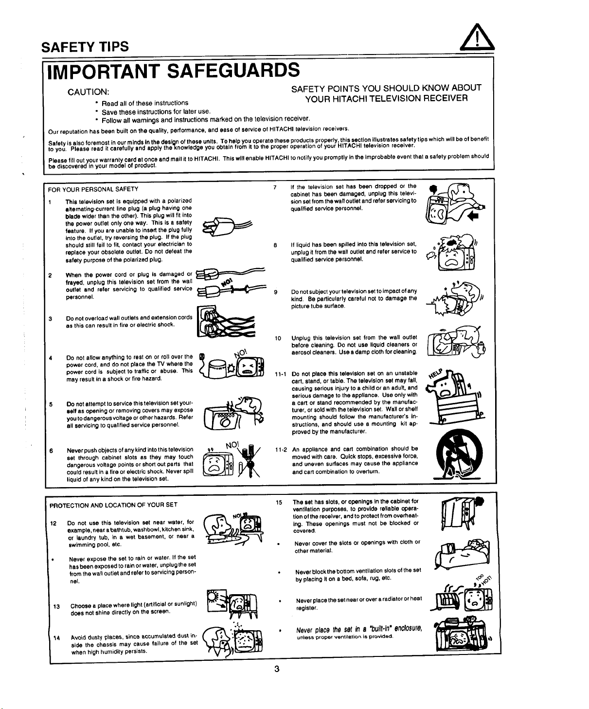
IMPORTANT SAFEGUARDS
CAUTION: SAFETY POINTS YOU SHOULD KNOW ABOUT
* Read all of these instructions YOUR HITACHI TELEVISION RECEIVER
* Save these instructions for later use.
* Follow all warnings and instructions marked on the television receiver.
Our reputation has been built on the quality, performance, end ease of service of HITACHI television receivers.
Safety is also foremost in our minds In the design of these units. To help you operate these products properly, this section Illustrates safety tips which will be of benefit
to you. Please read it carefully and apply theknowledge you obtain from it to the proper operation of your HITACHI television receiver,
Please fill out your warranty card at once and mall it to HITACHI. This will enable HITACHI to notify you promptly in the improbable event that a safety problem should
be discovered in your model of product.
FOR YOUR PERSONALSAFETY
This television set is equipped with a polarized
alternating-current line plug (a plug having one
blade wider than the other). This plug will fit into
the power outlet only one way. This is a safety
feature, If you are unable to insert the plug fully
Into the outlet, try reversing the plug. If the plug
should still fail to fit, contact your electrician to
replace your obsolete outlet. Do not defeat the
safety purpose of the polarized plug,
2 When the power cord or plug is damaged or I_€ =====_
frayed, unplug this television set from the walt
outlet and refer servicing to qualified service
personnel.
3 Do not overload wall outlets and extension cords |_
as this can result in fire or electric shock.
Do not allow anything to rest on or roll over the
power cord, and do not place the "IV where the
power cord is subject to traffic or abuse. This
may result in a shock or fire hazard.
Do not attempt to service this television set your-
=elf as opening or removing covers may expose
you to dangerous voltage orother haze rds. Refer
all servicing to qualified service personnel.
Never push objects of any kind into this television
set through cabinet slots as they may touch
dangerous voltage points or short out parts that
could resuit in a fire or electric shock, Never spill
liquid of any kind on the television set.
If the television set has been dropped or the
cabinet has been damaged, unplug this televi-
sion set from the wall outlet and refer servicing to
qualified service personnel.
If liquid has been spilled into this television set,
unplug it from the wall outlet and refer service to
qualified service personnel.
9
Do not subject your television set to impact of any
kind. Be particularly careful not to damage the
picture tube surface.
10
Unplug this television set from the wall outlet
before cleaning. Do not use liquid cleaners or
aerosol cleaners. Usa a damp cloth for cleaning.
11-1
Do not place this television set on an unstable
cart, stand, or table, The television set may fall,
causing serious injury to a child or an adult, and
serious damage to the appliance, Use only with
a cart or stand recommended by the manufac-
turer, or sold with the television set. Wall or shelf
mounting should follow the manufacturer's in-
structions, and should usa a mounting kit ap-
proved by the manufacturer.
1 1-2
An appliance and cart combination should be
moved with care. Quick stops, excessive force,
and uneven surfaces may cause the appliance
and cart combination to overturn.
o_h
PROTECTION AND LOCATION OF YOUR SET
12 Do not use this television set near water, for
example, near a bathtub, washbowl, kitchen sink,
Or laundry tub, in a wet basement, or near a
swimming pool, etc.
Never expose the set to rain or water. If the set
has been exposed to rain or water, unplug the set
from the wall outlet and refer to servicing person-
nel.
13 Choose s place where light (artificial or sunlight) V- .,,,_'_1{_,._ i_1 _
does not shine directly on the screen.
*.:.
14 Avo\d dusty p_eces, since accumulated dust _- ( ,,_,;_"_
side the chassis may cause failure of the set
when high humidity persists.
The set has slots, or openings In the cabinet for
ventilation purposes, to provide reliable opera-
tion of the receiver, and to protect from overheat-
ing. These openings must not be blocked or
covered.
Never cover the slots or openings with cloth or
other material.
Never block the bottom ventilation slots of the set
by placing it on a bed, sofa, rug, etc,
Never place the set near or over a radiator or heat
register.
Neverplacethesetin a "built.In"enclosure,
tin,ass proper ven_\_tion _s provided.
SAFETY TIPS
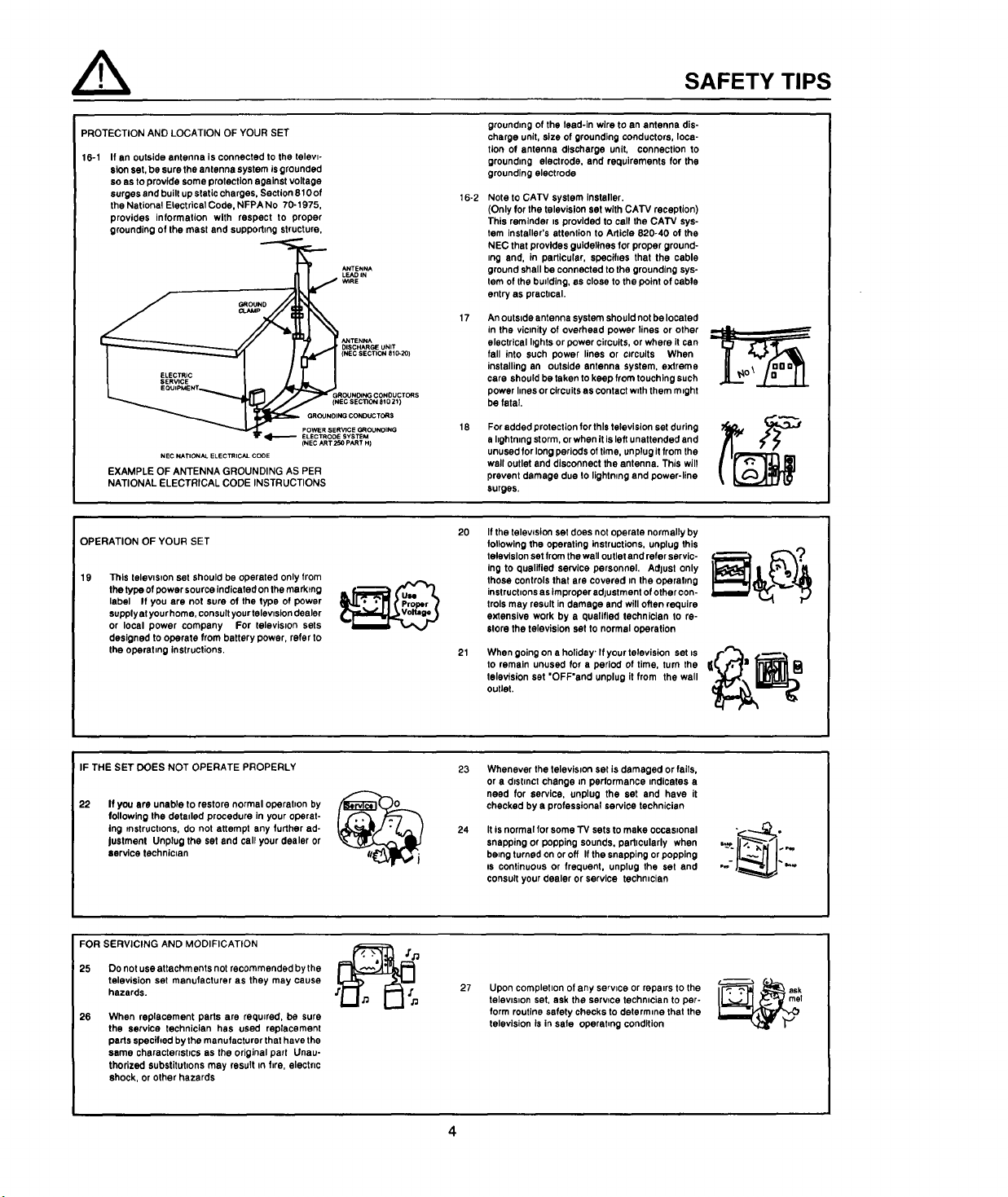
PROTECTION AND LOCATION OF YOUR SET
16-1 If an outside antenna is connected to the televt-
sion set, be sure the antenna system is grounded
so as to provide some protection against voltage
surges and built up static charges, Section 810 of
the National Electrical Code. NFPA No 70-1975,
provides information with respect to proper
grounding of the mast and suppodlng structure,
GROUNDING CONDUCTORS
POWER SERVICE GROUNOING
NEC NATIONAL ELECTRICAL CODE
EXAMPLE OF ANTENNA GROUNDING AS PER
NATIONAL ELECTRICAL CODE INSTRUCTIONS
(NEC ART 250 PART H)
OPERATION OF YOUR SET
19 This television set should be operated only from
the type of power source indicated on the marking
label If you are not sure of the type of power
supply at your home, consult your television dealer
or local power company For television sets
designed to operate from battery power, refer to
the operetmg instructions.
SYSTEM
grounding of the lead-in wire to an antenna dis-
charge unit, size of grounding conductors, loca-
tion of antenna discharge unit, connection to
grounding electrode, and requirements for the
grounding electrode
16-2
Note to CATV system Installer.
(Only for the television sat with CATV reception)
This reminder ts provided to call the CATV sys-
tem installer's attention to Article 820-40 of the
NEC that provides guidelines for proper ground-
trig end, in particular, specifies that the cable
ground shall be connected to the grounding sys-
tem of the building, as close to the point of cable
entry as practical.
An outside antenna system should not be located
in the viomity of overhead power lines or other
electrical hghts or power circuits, or where it can
fall into such power lines or c=rcults When
installing an outside antenna system, extreme
care should be taken to keep from touching such
power lines or circuits as contact with them m=ght
be fatal.
For added protection for this television set during
a lightning storm, orwhen it is left unattended and
unused for long periods of time, unplug itfrom the
wall outlet and disconnect the antenna. This will
prevent damage clue to lightning and power-line
surges.
2O21Ifthe telewsion set does not operate normally by
following the operating instructions, unplug this
television set from the wall outlet and refer servic-
Ing to qualified service personnel. Adlust only
those controls that ere covered in the operating
instructions as Improper adjustment of other con-
trois may result in damage and will often require
extensive work by a qualified technician to re-
store the television set to normal operation
When going on • holiday' If your television set ts
to remain unused for a period of time, turn the
television set "OFF'and unplug it from the wall
outlet.
IF THE SET DOES NOT OPERATE PROPERLY
22
If you are unable to restore normal operation by
following the detaded procedure in your operat-
ing instructions, do not attempt any further ad-
justment Unplug the set and call your dealer or
service technician
FOR SERVICING AND MODIFICATION
25 Do not use attachments not recommended by the
television set manufacturer as they may cause
hazards.
26
When replacement parts are required, be sure
the service technician has used replacement
parts specified by the manufacturer that have the
same charectenst_cs as the original part Unau-
thorized substitut=ons may result tn fire, electric
shock, or other hazards
23
Whenever the television set is damaged or fails,
or a distract change in performance indicates a
need for service, unplug the set and have it
checked by 8 professional service technician
24
Itis normal for some "rv sets to make occasional
snapping or popping sounds, particularly when
being turned on or off If the snapping or popping
Is continuous or frequent, unplug the set and
consult your dealer or service technician
27
Upon completion of any service or repairs to the
television set, ask the serwce technician to per-
form routine safety checks to determine that the
television is in safe operet_ng condition
PICTURE CAUTIONS
WARNING

ACCESSORIES
Check to make sure you have the following accessories before disposing of the packing material.
1. Remote Control Unit (See Part No. Below)
2. Two "AA" size, 1.5V batteries (For Remote Control Unit)
For information regarding how to obtain these accessories, please call TOLL FREE 1-800-448-2244 for your nearest
HITACHI Authorized Parts Distributorinthecontinental United States. ForAlaska and Hawaii, pleasecontactyournearest
HITACHI Regional office.
PART NAME PART NO. ILLUSTRATION
27CX15B
CLU-414UI
REMOTE CONTROL
27CX1B/20SA5B
CLU-361U
REMOTE CONTROL
27V TELEVISION STAND
SP271B
(Not included, order Separately)
HL00223
HL00551
H530021
VCR=ONTR_
(_o(_
Q_ (Z) (Z)_'
CLU-414UI
au._,u
CLU-361U
CUSTOM HITACHI
TELEVISION STAND
Excellent for VCR and
videotape storage. Special
Features: curved smoke
glass doors adjustable
shelf. Available in Black.
!l_cAUTION:
The television stand model SP271B is designed for use only with HITACHI TV models 27CX1B I
and 27CX15B. Use with other television equipment may result in instability, causing possible
injury.
I
I
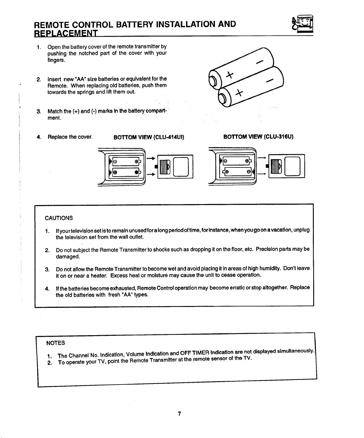
REMOTE CONTROL BATTERY INSTALLATION AND
REPLACEMENT
1.
Open the battery cover of the remote transmitter by
pushing the notched part of the cover with your
fingers.
,
Insert new "AA" size batteries or equivalent for the
Remote. When replacing old batteries, push them
towards the springs and lift them out.
; i
,
Match the (+) and (-) marks tn the battery comped-
ment.
4. Replace the cover.
BOTTOMVIEW (CLU-414UI)
BOTTOM VIEW (CLU-316U)
CAUTIONS
1. Ifyour television setis toremain unused foralong periodoftime, forlnstance, when yougo ona vacation, unplug
the television set from the wall outlet.
2. Do not subject the Remote Transmitter toshocks suchas droppingit on the floor, etc. Precision parts may be
damaged.
3. Do not allow the Remote Transmitter to become wet and avoid placing itin areas ofhigh humidity. Don't leave
it on or near a heater. Excess heat or moisture may cause the unit to cease operation.
4. If the batteries become exhausted, Remote Control operation may become erratic or stopaltogether. Replace
the old batteries with fresh "AA" types.
NOTES
1. 3"he Channel No. Indication, Volume Indication and OFF TIMER Indication are not displayed simultaneously.
2. 3"ooperate your TV, point the Remote Transmitter at the remote sensor ofthe TV.

HOW TO SET UP YOUR NEW HITACHI COLOR TV
ANTENNA
Unless yourTV is connected to a cable TV system orto a centralized antenna system, a good outdoor color TV antenna
isrecommended for the best performance. However, if youare located in an exceptionally good signal area that is free
from interference and multiple image ghosts, an indoor antenna may be sufficient.
LOCATION
Select an area where sunlight or brightindoor illumination will notfall directly on the picture screen. Also, be sure that
the location selected allows a free flow of air to and from the cover of the set.
To avoid cabinet warping, cabinet color changes, and increased chance of set failure, do not place the TV where
temperatures can become excessively hot. For example, in direct sunlight or near a heating appliance, etc.
VIEWING
The major benefit of the HITACHI Color Television is its
viewing screen. To see this screen at itsbest, test various
locations in the room tofindthe best spotfor viewing. The
drawings give several suggestions.
The best picture Isseen bysittingdirectly infront ofthe TV
and about 6 to 9 feet from the screen.
Duringdaylighthours,reflectionsfromoutsidelightmay
appearon the screen. If so, drapesor screenscanbe
usedtoreducethereflectionorthe TV canbe locatedin
a differentsectionofthe room.
If the TV's audio outputwill be connectedto a Hi-Fi
system'sexternalspeakers,thebestaudioperformance
willbe obtainedbyplacingthe speakersequidistantfrom
eachsideofthereceivercabinetandascloseaspossible
totheheightof thepicturescreencenter. Forbeststereo
separation,place the externalspeakersat least4 feet
from thesideof theTV. Placethesurroundspeakersto
thesideor behindthe viewingarea. Differencesinroom
sizesand acousticalenvironmentswillrequiresomeex-
perimentationwith speaker placementfor best perfor-
mance.
4' MINIMUM
4' MINIMUM
_CAUTION: The magnetic field of external speakers may cause the TV pictureto distort ifthe
placed too close to the television. Move the speakers away fromthe TV until thereSpeakerSisnopicture
distortion.
are
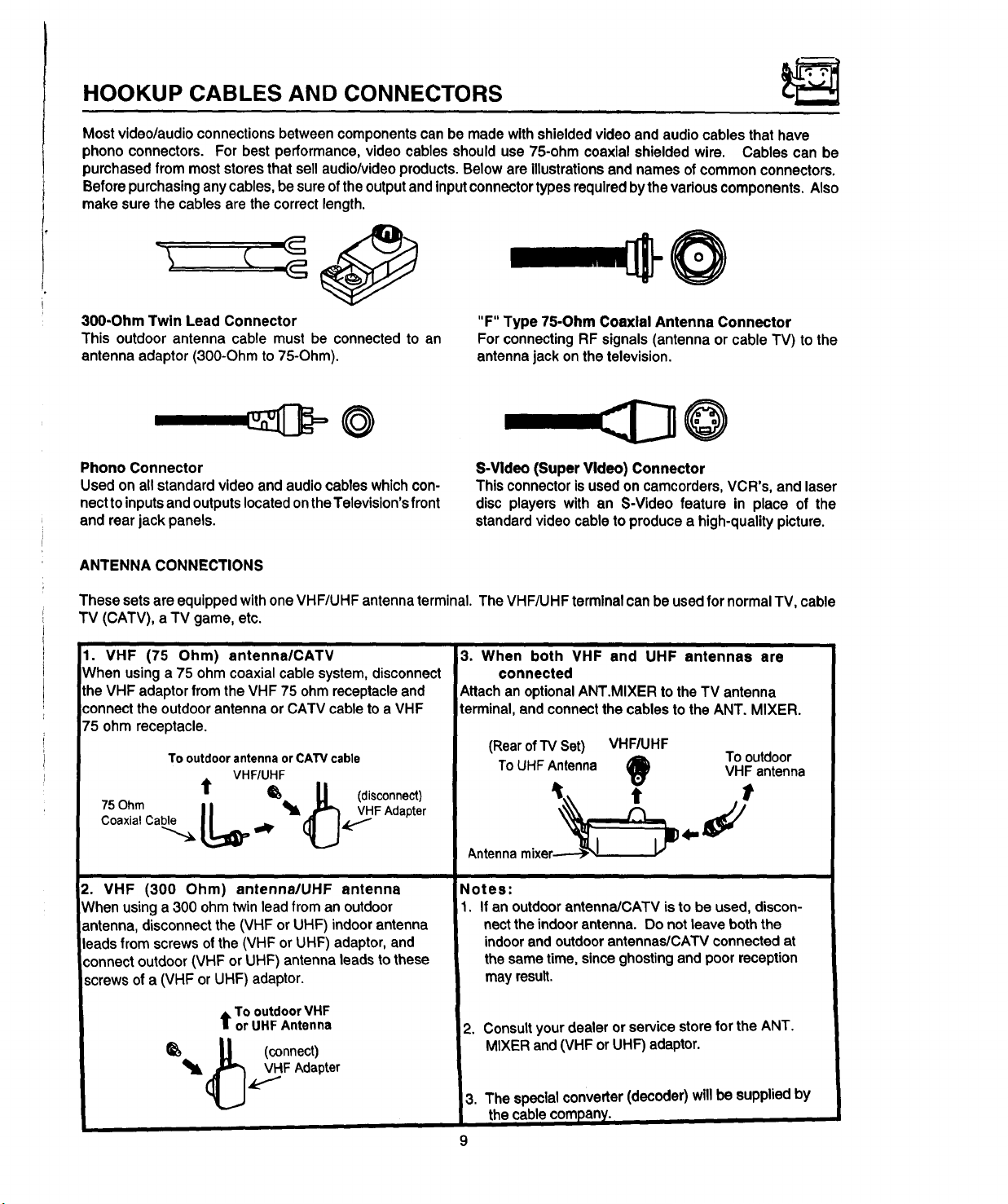
HOOKUP CABLES AND CONNECTORS
Most video/audioconnectionsbetweencomponentscanbe madewithshieldedvideoandaudiocablesthat have
phonoconnectors. For bestperformance,videocablesshoulduse 75-ohm coaxialshieldedwire. Cables can be
purchasedfrommoststoresthat sellaudio/videoproducts.Beloware illustrationsandnamesofcommonconnectors.
Beforepurchasinganycables,besureoftheoutputandinputconnectortypesrequiredbythevariouscomponents,Also
makesurethecablesare thecorrectlength.
300-Ohm Twin Lead Connector
This outdoorantenna cable mustbe connectedto an
antennaadaptor(300-Ohmto75-Ohm).
"F" Type 7S-OhmCoaxial Antenna Connector
ForconnectingRFsignals(antennaor cableTV) to the
antennajackonthetelevision.
---,::D@
Phono Connector
Usedon allstandardvideo andaudiocableswhichcon-
necttoinputsandoutputslocatedontheTelevision'sfront
andrearjack panels.
ANTENNA CONNECTIONS
ThesesetsareequippedwithoneVHF/UHFantennaterminal.The VHF/UHFterminalcanbe usedfor normalTV,cable
TV (CATV),a TV game,etc.
1. VHF (75 Ohm) antenna/CATV
When using a 75 ohm coaxial cable system, disconnect
the VHF adaptor from the VHF 75 ohm receptacle and
connect the outdoor antenna or CATV cable to a VHF
75 ohm receptacle.
To outdoor antenna or CATV cable
VHF/UHF
t _*- U (disconnect)
CoaxialCable
75Ohm L_ .l_,_FAdapte r
S-Video (Super Video) Connector
This connector is used on camcorders, VCR's, and laser
disc players with an S-Video feature in place of the
standard video cable to produce a high-quality picture.
i /
3. When both VHF and UHF antennas are
connected
Attachan optionalANT.MIXERto the TV antenna
terminal,and connectthecablesto the ANT. MIXER.
(Rearof TV Set)
To UHF Antenna
VHF/UHF
VHF antenna
t
Tooutdoor
Antennamixer-_ I
2. VHF (300 Ohm) antenna/UHF antenna
Whenusinga 300 ohmtwinleadfroman outdoor
antenna,disconnectthe(VHFor UHF) indoorantenna
leadsfromscrewsofthe (VHForUHF) adaptor,and
connectoutdoor(VHF orUHF) antennaleadstothese
screwsofa (VHF or UHF)adaptor.
t Tooutdoor VHF
or UHF Antenna
_ U (connect)
Notes:
1. If an outdoor antenna/CATV is to be used, discon-
nectthe indoor antenna. Do not leave both the
indoor and outdoorantennas/CAW connected at
the same time, since ghosting and poor reception
may result.
2. Consult your dealer or service store for the ANT.
MIXER and (VHF or UHF) adaptor.
3. The specialconverter(decoder)willbe suppliedby
thecablecompany.
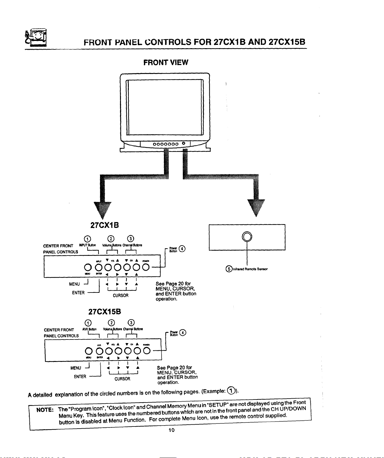
FRONT PANEL CONTROLS FOR 27CXIB AND 27CX15B
FRONT VIEW
27CX1B
6) ® ®
o665%--
_u _'_ '• I_ 0
MENU • • v • See Page 20 for
.J___J I I I I
ENTER l I I I MENU,CURSOR,
CURSOR andENTER button
operation.
27CX15B
(]) @ @
£S\%%%
MENU • • v - See Page20 for
_J } I I I I
ENTER_ MENU, CURSOR,
A detailed explanation of the circled numbers is on the following pages. (Example: (_)).
L I I I
CURSOR andENTER button
operation.
NOt'E: The"Program tcon","Clock Icon"and Channel Memory Menu in"SETUP" are notdisplayed using the Front }
Menu Key. This feature uses the numbered buttonswhich are not in the front panel and the OH UP/DOWN
button is disabled at Menu Function. For complete Menu Icon, use the remote control supplied.
10
FRONT PANEL CONTROLS FOR 20SA5B
FRONT VIEW
FRONT PANEL CONTROLS
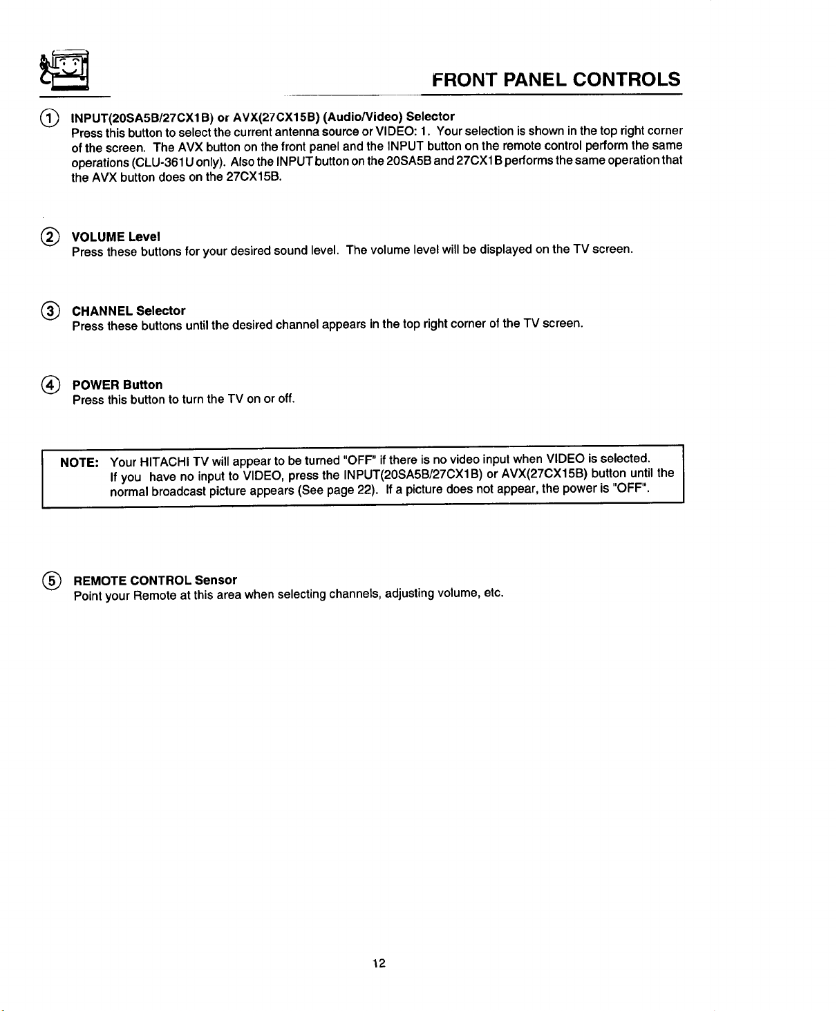
INPUT(20SA5B/27CX1 B) or AVX(27CX15B) (Audio/Video) Selector
®
Press this button to select the current antenna source or VIDEO: 1. Your selection isshown in the top right corner
of the screen. The AVX button on the front panel and the INPUT button on the remote control perform the same
operations (CLU-361U only). Alsothe INPUT button on the 20SA5B and 27CX1B performs the same operation that
the AVX button does on the 27CX15B.
(_ VOLUME Level
Press thesebuttonsfor yourdesiredsoundlevel. Thevolumelevelwillbe displayedontheTV screen.
(_) CHANNEL Selector
Pressthese buttonsuntilthe desiredchannelappearsinthetoprightcorneroftheTV screen.
(_) POWER Button
Pressthisbuttonto turnthe TV onor off.
NOTE: Your HITACHI TV will appear to be turned "OFF" ifthere is no video input when VIDEO is selected.
If you have no input to VIDEO, press the INPUT(20SA5B/27CX1B) or AVX(27CX15B) button untilthe
normal broadcast picture appears (See page 22). If a picture does not appear, the power is "OFF".
(_ REMOTE CONTROL Sensor
Point your Remote at this area when selecting channels, adjusting volume, etc.
12
REAR PANEL JACKS
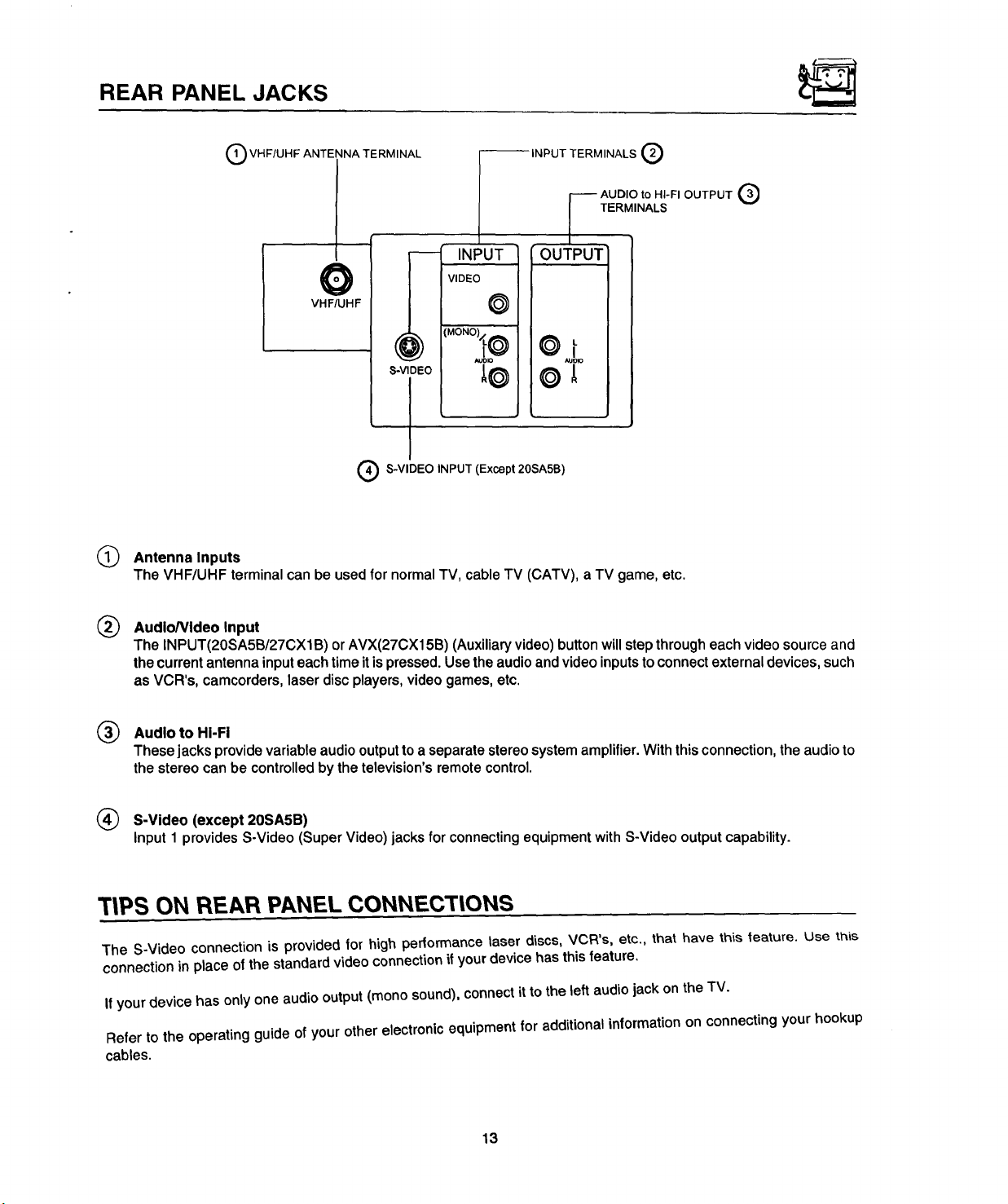
Q VHF/UHF ANTENNA TERMINAL
--INPUT TERMINALS Q
j----- AUDIO to HI-FI OUTPUT
| TE.M,NA'S®
OUTPUT"
VHF/UHF
INPUT
VIDEO
©
@
S-VIDEO
I
(_ S-VIDEO INPUT (Except 20SA5B)
(_ Antenna Inputs
The VHF/UHF terminal can be used for normal TV, cable TV (CATV), a TV game, etc.
® AudloNideo Input
The INPUT(20SA5B/27CXIB) orAVX(27CX15B)(Auxiliaryvideo)button willstepthrougheach video sourceand
thecurrentantennainputeachtimeitispressed.Usetheaudioandvideoinputstoconnectexternaldevices,such
as VCR's,camcorders,laserdiscplayers,videogames,etc.
(_) Audio to HI-Fi
These jacks provide variable audio output to a separate stereo system amplifier. With this connection, the audio to
the stereo can be controlled by the television's remote control.
S-Video (except 20SA5B)
Input1 providesS-Video(SuperVideo)jacksforconnectingequipmentwithS-Videooutputcapability.
T|PS ON REAR PANEL CONNECTtONS
The S-Video connection is provided for high perlormance laser discs, VCR's, etc., that have this teature. Use this
connection in place of the standard video connection if your device has this feature.
If your device has only one audio output (mono sound), connect it to the left audio jack on the TV.
Refer to the operating guide of your other electronic equipment for additional information on connecting your hookup
cables.
13
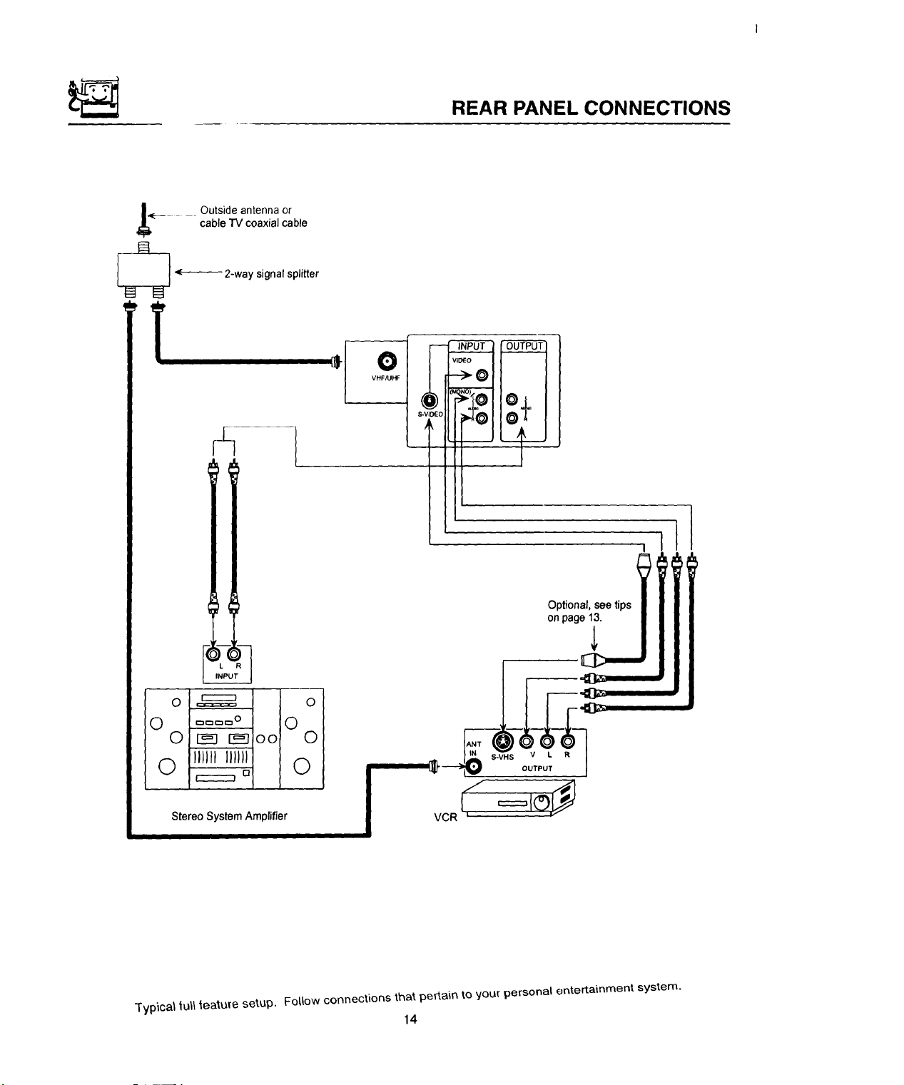
REAR PANEL CONNECTIONS
_i__ - .... Outside antenna or
_ _----_ 2-way signalsplitter
cable "IV coaxial cable
O
VHF/UHF
I
Optional, see tips I
on pag_
0 ,======= 0
0 .... o 0
0 _-n r_n oo 0
0 IJJJHJlJJJ_ 0
Stereo System Amplifier
-Iyptcal lult _eatu[e setup. Follow connections that pertain to your personal entertainment system.
[]
14

EXTERNAL CONNECTIONS
CONNECTING EXTERNAL AUDIO AMPLIFIER
Tocontroltheaudiolevelof anexternalaudioamplifierwiththe remotetransmitter,connectthe systemas shownbelow
in Fig.1.
(REAROF SET)
AUDIO TO HI-FI TERMINAL
TOAUDIO INPUTTERMINAL = ( Q
OF EXTERNALAMPLIFIER_
),_, _C_
EXTERNAL
SPEAKERS
NOTE: To preventdamagetothe speakeranddistortedsound,setthevolumecontrolofthe audioamplifierlower
andadjustthesoundlevelusingthe volumecontrolonthe remotetransmitteroftheTV set.
AUDIO AMPLIFIER
OUTPUT
d
EXTERNAL
SPEAKERS
J
15
 Loading...