

Page 1
SERVICE MANUAL
TECHNICAL INFORMATION
FOR SERVICE PERSONNEL ONLY
RAS-18CP5
RAS-24CP5
PM
NO. 0169E
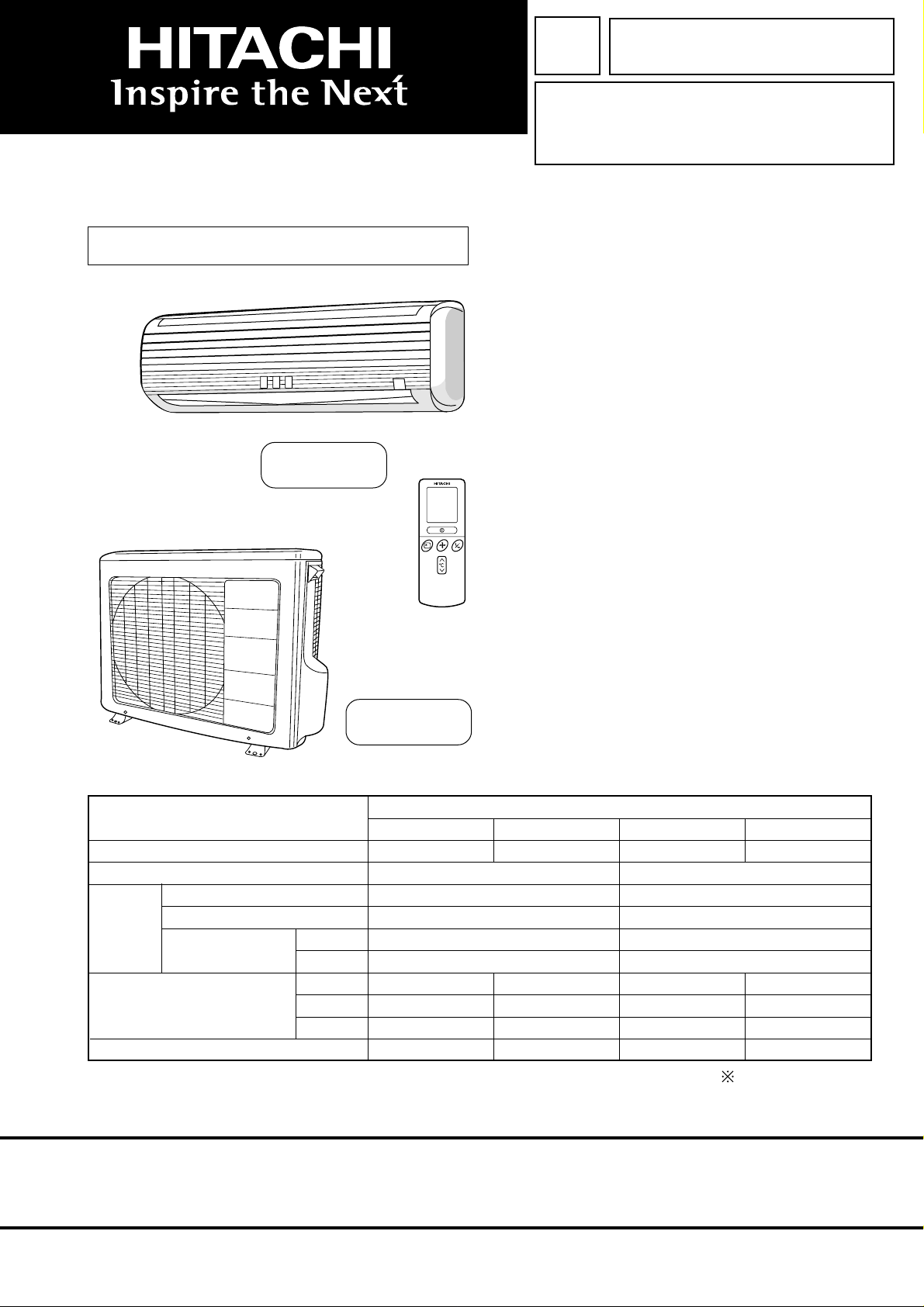
RAS-18CP5/RAC-18CP5
RAS-24CP5/RAC-24CP5
REFER TO THE FOUNDATION MANUAL
CONTENTS
SPECIFICATIONS ----------------------------------------------------- 5
HOW TO USE ---------------------------------------------------------- 8
CONSTRUCTION AND DIMENSIONAL DIAGRAM ------- 30
MAIN PARTS COMPONENT ------------------------------------- 32
WIRING DIAGRAM -------------------------------------------------- 34
CIRCUIT DIAGRAM ------------------------------------------------- 37
PRINTED WIRING BOARD LOCATION DIAGRAM ------- 39
BLOCK DIAGRAM --------------------------------------------------- 41
BASIC MODE --------------------------------------------------------- 43
REFRIGERATING CYCLE DIAGRAM ------------------------- 49
DESCRIPTION OF MAIN CIRCUIT OPERATION --------- 50
AUTO SWING FUNCTION ---------------------------------------- 54
SERVICE CALL Q & A -------------------------------------------- 55
TROUBLE SHOOTING --------------------------------------------- 60
PARTS LIST AND DIAGRAM ------------------------------------ 63
RAC-18CP5
RAC-24CP5
SPECIFICATIONS
TYPE
MODEL
POWER SOURCE
TOTAL INPUT
COOLING
DIMENSIONS
(mm)
NET WEIGHT
TOTAL AMPERES
CAPACITY
(W)
(A)
(kW)
(B.T.U./h)
W
H
D
(kg)
INDOOR UNIT OUTDOOR UNITINDOOR UNITOUTDOOR UNIT
RAS-18CP5 RAC-18CP5
1 Ø, 50 Hz, 220 ~ 240V
1790 ~ 1950
8.30 ~ 8.50
5.10 ~ 5.20
17,410 ~ 17,750
1030
295
183
12
(WALL TYPE)
750
570
280
43
RAS-24CP5 RAC-24CP5
1 Ø, 50 Hz, 220 ~ 240V
1030
295
183
12
SPECIFICATIONS AND PARTS ARE SUBJECT TO CHANGE FOR IMPROVEMENT
2270 ~ 2410
10.90 ~ 10.60
6.30 ~ 6.30
21,500 ~ 21,500
850
650
298
60
After installation
ROOM AIR CONDITIONER
FEBRUARY 2003
INDOOR UNIT + OUTDOOR UNIT
Refrigeration & Air-Conditioning
Page 2
SAFETY DURING REPAIR WORK
DANGER
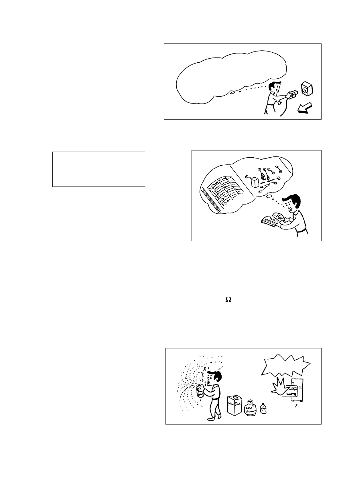
1. In order to disassemble and repair
the unit in question, be sure to
disconnect the power cord plug from
the power outlet before starting the
work.
First, I must disconnect
the power cord plug
from the power outlet.
2. If it is necessary to replace any parts, they should be replaced with respective genuine parts for the unit, and
the replacement must be effected in correct manner according to the instructions in the Service Manual of the
unit.
If the contacts of electrical parts
are defective, replace the
electrical parts without trying to
repair them.
3. After completion of repairs, the initial state
should be restored.
4. Lead wires should be connected and laid as in
the initial state.
5. Modification of the unit by user himself should
absolutely be prohibited.
6. Tools and measuring instruments for use in repairs or inspection should be accurately calibrated in advance.
7. In installing the unit having been repaired, be careful to prevent the occurence of any accident such as electrical
shock, leak of current, or bodily injury due to the drop of any part.
8. To check the insulation of the unit, measure the insulation resistance between the power cord plug and
grounding terminal of the unit. The insulation resistance should be 1M or more as measured by a 500V
DC megger.
9. The initial location of installation such as window, floor or the other should be checked for being and safe
enough to support the repaired unit again.
If it is found not so strong and safe, the unit should be installed at the initial location reinforced or at a new
location.
10. Any inflammable thing should never
be placed about the location of
installation.
11. Check the grounding to see whether
it is proper or not, and if it is found
improper, connect the grounding
terminal to the earth.
– 1 –
Page 3
WORKING STANDARDS FOR PREVENTING BREAKAGE OF SEMICONDUCTORS
1. Scope
The standards provide for items to be generally observed in carrying and handling semiconductors in relative
manufacturers during maintenance and handling thereof. (They apply the same to handling of abnormal
goods such as rejected goods being returned).
2. Object parts
(1) Micro computer
(2) Integrated circuits (IC)
(3) Field-effect transistors (FET)
(4) P.C. boards or the like on which the parts mentioned in (1) and (2) of this paragraph are equipped.
3. Items to be observed in handling
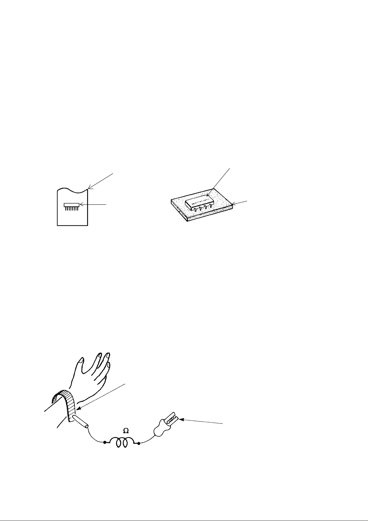
(1) Use a conductive container for carrying and storing of parts. (Even rejected goods should be handled in
the same way).
A conductive polyvinyl bag
IC
Fig. 1. Conductive Container
(2) When any part is handled uncovered (in counting, packing and the like), the handling person must always
use himself as a body earth. (Make yourself a body earth by passing one M ohm earth resistance through
a ring or bracelet).
(3) Be careful not to touch the parts with your clothing when you hold a part even if a body earth is being
taken.
(4) Be sure to place a part on a metal plate with grounding.
(5) Be careful not to fail to turn off power when you repair the printed circuit board. At the same time,
try to repair the printed circuit board on a grounded metal plate.
IC
Conductive sponge
Body earth
(Elimik conductive band)
1M
Fig. 2. Body Earth
Clip for connection with a
grounding wire
– 2 –
Page 4
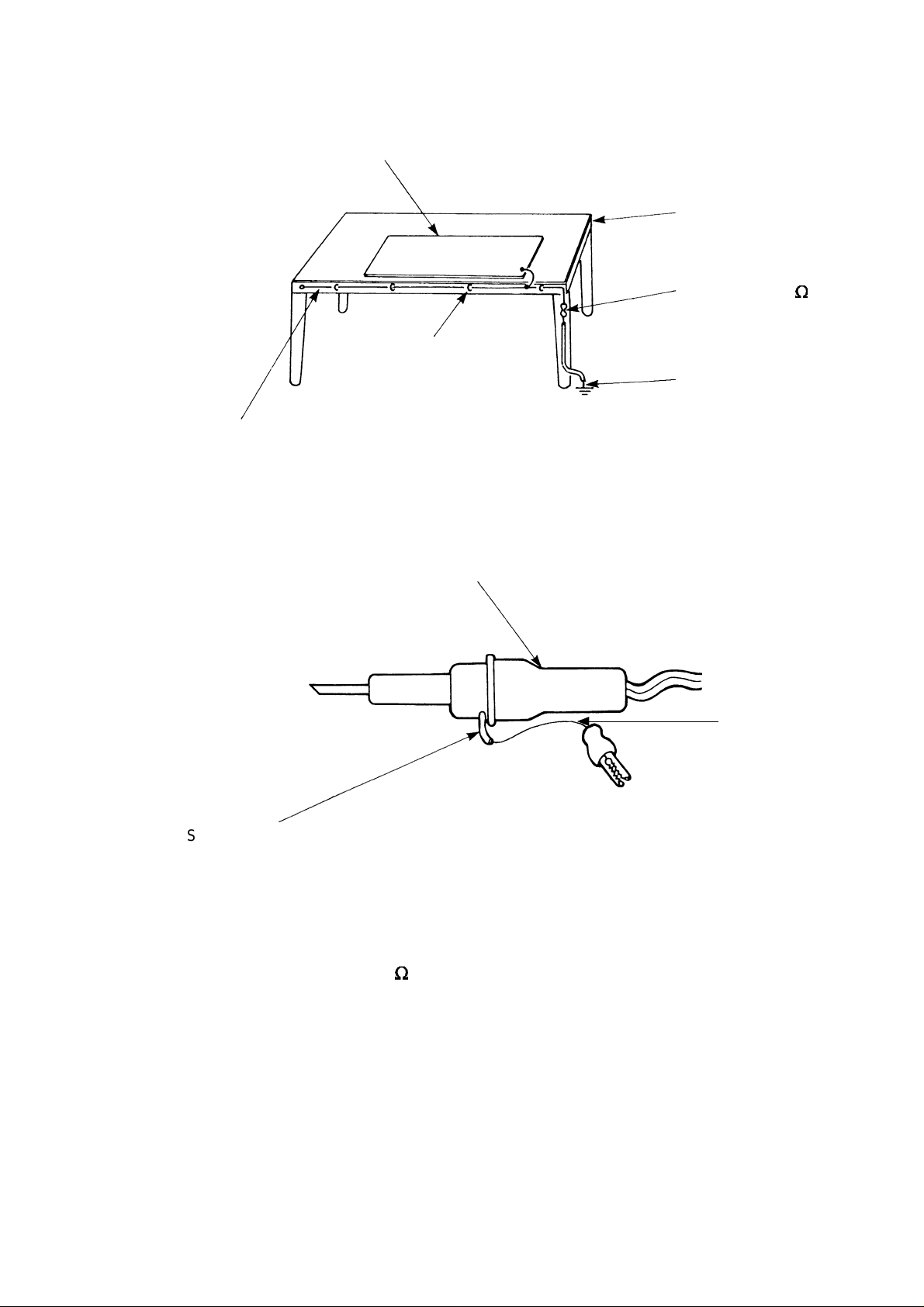
(6) Use a three wire type soldering iron including a grounding wire.
Metal plate (of aluminium, stainless steel, etc.)
Staple
Bare copper wire (for body earth)
Fig. 3. Grounding of the working table
Working
table
Resistor of 1 M (1/2W)
Earth wire
Soldering iron
2
Screw stop at the screwed
part using a rag plate
Fig. 4. Grounding a soldering iron
Use a high insulation mode (100V, 10M or higher) when ordinary iron is to be used.
(7) In checking circuits for maintenance, inspection or some others, be careful not to have the test probes of the
measuring instrument shortcircuit a load circuit or the like.
Grounding
wire
– 3 –
Page 5

CAUTION
!
1. In quiet or stopping operation, slight flowing noise of refrigerant in the refrigerating cycle is heard occasionally,
but this noise is not abnormal for the operation.
2. When it thunders near by, it is recommended to stop the operation and to disconnect the power cord plug
from the power outlet for safety.
3. The room air conditioner does not start automatically after recovery of the electric power failure for
preventing fuse blowing. Re-press START/STOP button after 3 minutes from when unit stopped.
4. If the room air conditioner is stopped by adjusting thermostat, or missoperation, and re-start in a moment,
there is occasion that the cooling and heating operation does not start for 3 minutes, it is not abnormal
and this is the result of the operation of IC delay circuit. This IC delay circuit ensures that there is no
danger of blowing fuse or damaging parts even if operation is restarted accidentally.
5. This room air conditioner should not be used at the cooling operation when the outside temperature is
below 10°C (50°F).
– 4 –
Page 6
SPECIFICATIONS
MODEL
FAN MOTOR
FAN MOTOR CAPACITOR
FAN MOTOR PROTECTOR
COMPRESSOR
COMPRESSOR MOTOR CAPACITOR
OVERLOAD PROTECTOR
OVERHEAT PROTECTOR
FUSE (MICRO COMPUTER CIRCUIT)
POWER RELAY
POWER SWITCH
RAS-18CP5
20 W
NO
NO
–
NO
NO
NO
3.15A
G4A
YES
RAC-18CP5
30 W
2.5µF, 450V
YES (INTERNAL)
SHY33MC4-E
50µF, 440VAC
(INTERNAL)
(INTERNAL)
NO
NO
NO
TEMPORARY SWITCH
SERVICE SWITCH
TRANSFORMER
VARISTOR
NOISE SUPPRESSOR
THERMOSTAT
REMOTE CONTROL SWITCH (LIQUID CRYSTAL)
FUSE CAPACITY
UNIT
REFRIGERANT CHARGING
VOLUME
(Refrigerant R22)
PIPES (MAX. 15m)
PIPES (MIN. 15m)
NO
YES
YES (SWITCHING
POWER SUPPLY)
450NR
NO
YES(IC)
YES
20 A TIME DELAY FUSE
---------- 1250g
ADDITIONAL REFRIGERANT R22 AT
10g PER EVERY METER IF PIPE
LENGTH MORE THAN 8m.
NO
YES
NO
NO
NO
YES(IC)
NO
– 5 –
Page 7
SPECIFICATIONS
MODEL
FAN MOTOR
FAN MOTOR CAPACITOR
FAN MOTOR PROTECTOR
COMPRESSOR
COMPRESSOR MOTOR CAPACITOR
OVERLOAD PROTECTOR
OVERHEAT PROTECTOR
FUSE (MICRO COMPUTER CIRCUIT)
POWER RELAY
POWER SWITCH
RAS-24CP5
20 W
NO
NO
–
NO
NO
NO
3.15A
G4A
YES
RAC-24CP5
40 W
2.5µF, 450V
YES (INTERNAL)
SHV33YC1-E
60µF, 440VAC
(INTERNAL)
(INTERNAL)
NO
NO
NO
TEMPORARY SWITCH
SERVICE SWITCH
TRANSFORMER
VARISTOR
NOISE SUPPRESSOR
THERMOSTAT
REMOTE CONTROL SWITCH (LIQUID CRYSTAL)
FUSE CAPACITY
REFRIGERANT CHARGING
VOLUME
(Refrigerant R22)
PIPES (MAX. 15m)
PIPES (MIN. 15m)
NO
YES
YES (SWITCHING
POWER SUPPLY)
450NR
NO
YES(IC)
YES
30 A TIME DELAY FUSE
---------- 1600gUNIT
ADDITIONAL REFRIGERANT R22 AT
20g PER EVERY METER IF PIPE
LENGTH MORE THAN 8m.
NO
YES
NO
NO
NO
YES(IC)
NO
– 6 –
Page 8
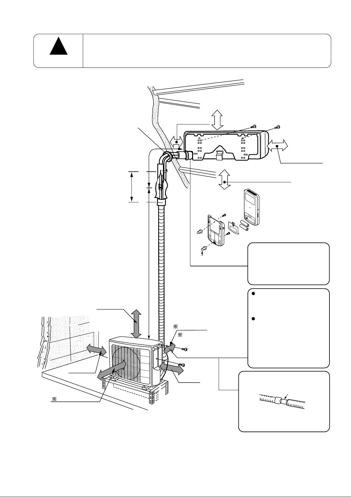
Figure showing the installation of Indoor and Outdoor unit
!
CAUTION
The installation height of indoor unit must be 2.5m or more from floor in a non public area
above 50mm
above 100mm
above 100mm
above
0.45m
2,500mm or more
above 300mm
must not bend
above 100mm
above 700mm
above 200mm
above 50mm when
installed on the
(
ceiling of balcony
Maximum pipe length 15m
Minimum pipe length 5m
)
Plug
above 100mm
give clearance as
wide as possible
above 200mm
The indoor piping should be
insulated with the enclosed
insulation pipe. (If the
insulator is insufficient,
please use commersial
products).
The difference in height
between the indoor and
outdoor unit should be
kept max 5m.
The connecting pipe, no
matter big or small,
should all be insulated
with insulation pipe and
then warapped with vinyl
tape. (The insulator will
deteriorate if it is not
wrapped with tape).
The connection of insulated
drain hose.
inner diameter ø 16mm
Please use insulated drain
hose for the indoor piping
(commercial product).
– 7 –
Page 9
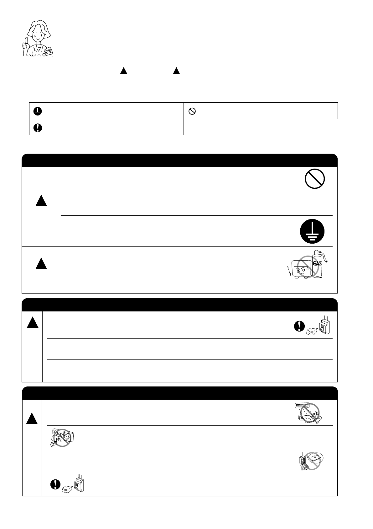
SAFETY PRECAUTION
●
Please read the “Safety Precaution” carefully before operating the unit to ensure correct usage of the unit.
●
Pay special attention to signs of “ Warning” and “ Caution”. The “Warning” section contains matters which,
if not observed strictly, may cause death or serious injury. The “Caution” section contains matters which may
result in serious consequences if not observed properly. Please observe all instructions strictly to ensure safety.
●
The sign indicate the following meanings.
!
!
Make sure to connect earth line.
Indicates the instructions that must be followed.
●
Please keep this manual after reading.
PRECAUTIONS DURING INSTALLATION
● Do not reconstruct the unit.
Water leakage, fault, short circuit or fire may occur if you reconstruct
the unit by yourself.
● Please ask your sales agent or qualified technician for the installation
!
WARNING
!
CAUTION
of your unit. Water leakage, short circuit or fire may occur if you install
the unit by yourself.
●
Please use earth line.
Do not place the earth line near water or gas pipes, lightning-conductor,
or the earth line of telephone. Improper installation of earth line may
cause electric shock.
● A circuit breaker should be installed depending on the mounting site of
the unit. Without a circuit breaker, the danger of electric shock exists.
●
Do not install near location where there is flammable gas. The outdoor
unit may catch fire if flammable gas leaks around it.
●
Please ensure smooth flow of water when installing the drain hose.
The sign in the figure indicates prohibition.
W
A
R
N
N
G
!
W
A
R
N
N
G
PRECAUTIONS DURING SHIFTING OR MAINTENANCE
●
Should abnormal situation arises (like burning smell), please stop operating the unit
!
I
and turn off the circuit breaker. Contact your agent. Fault, short circuit or fire may
occur if you continue to operate the unit under abnormal situation.
● Please contact your agent for maintenance. Improper self maintenance may cause
electric shock and fire.
●
Please contact your agent if you need to remove and reinstall the unit. Electric
shock or fire may occur if you remove and reinstall the unit yourself improperly.
PRECAUTIONS DURING OPERATION
●
Avoid an extended period of direct air flow for your health.
●
Do not put objects like thin rods into the panel of blower and suction side
because the high-speed fan inside may cause danger.
●
I
Do not use any conductor as fuse wire, this could cause fatal accident.
●
During thunder storm, disconnect and turn off the circuit breaker.
– 8 –
Page 10
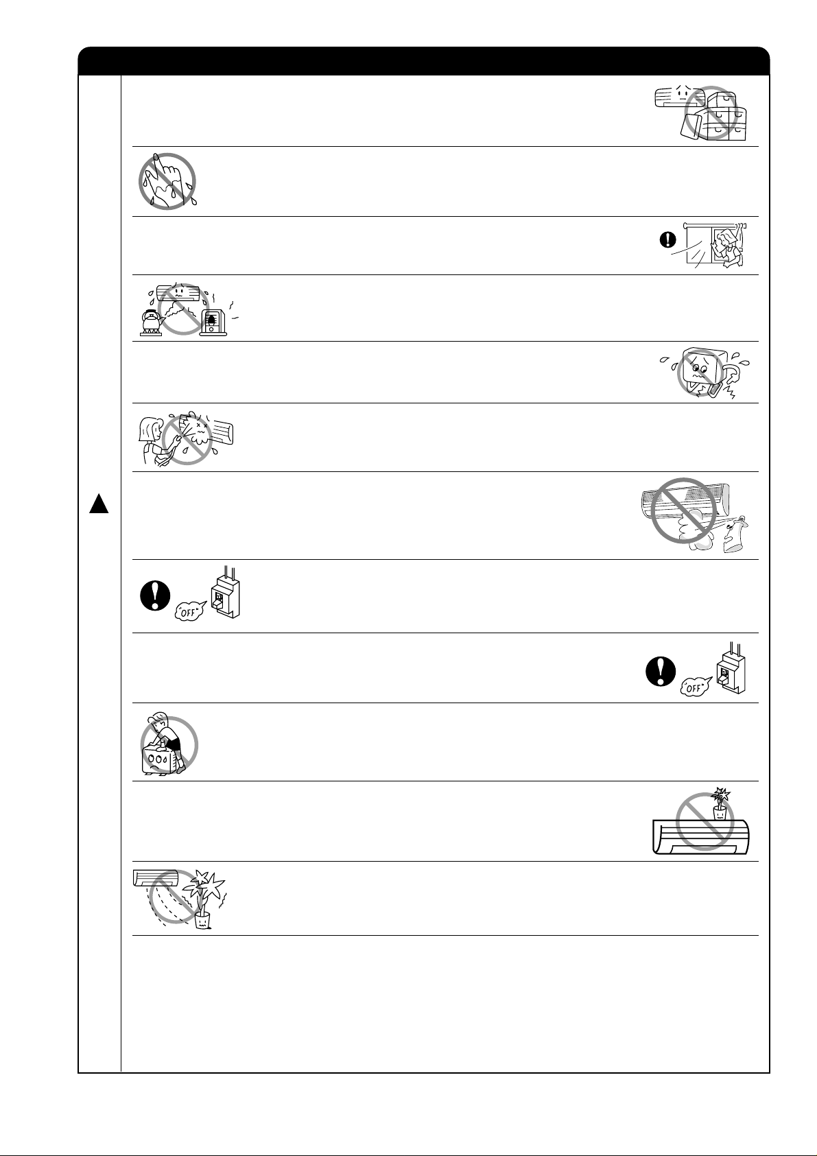
PRECAUTIONS DURING OPERATION
● The product shall be operated under the manufacturer specification and not
for any other intended use.
●
Do not attempt to operate the unit with wet hands, this could cause fatal
accident.
● When operating the unit with burning equipments, regularly ventilate the
room to avoid oxygen insufficiency.
●
Do not direct the cool air coming out from the air-conditioner panel to face
household heating apparatus as this may affect the working of apparatus such
as the electric kettle, oven etc.
● Please ensure that outdoor mounting frame is always stable, firm and without
defect. If not, the outdoor unit may collapse and cause danger.
●
Do not splash or direct water to the body of the unit when cleaning it as this
may cause short circuit.
● Do not use any aerosol or hair sprays near the indoor unit. This chemical can
!
C
A
adhere on heat exchanger fin and blocked the evaporation water flow to drain
pan. The water will drop on tangential fan and cause water splashing out from
indoor unit.
U
T
I
● Please switch off the unit and turn off the circuit breaker during cleaning, the
high-speed fan inside the unit may cause danger.
O
N
● Turn off the circuit breaker if the unit is not to be operated for a long period.
● Do not climb on the outdoor unit or put objects on it.
●
Do not put water container (like vase) on the indoor unit to avoid water dripping
into the unit. Dripping water will damage the insulator inside the unit and
causes short-circuit.
● Do not place plants directly under the air flow as it is bad for the plants.
●
When operating the unit with the door and windows opened, (the room humidity is always above
80%) and with the air deflector facing down or moving automatically for a long period of time, water
will condense on the air deflector and drips down occasionally. This will wet your furniture. Therefore,
do not operate under such condition for a long time.
●
If the amount of heat in the room is above the cooling or heating capability of the unit (for example:
more people entering the room, using heating equipments and etc.), the preset room temperature
cannot be achieved.
– 9 –
Page 11
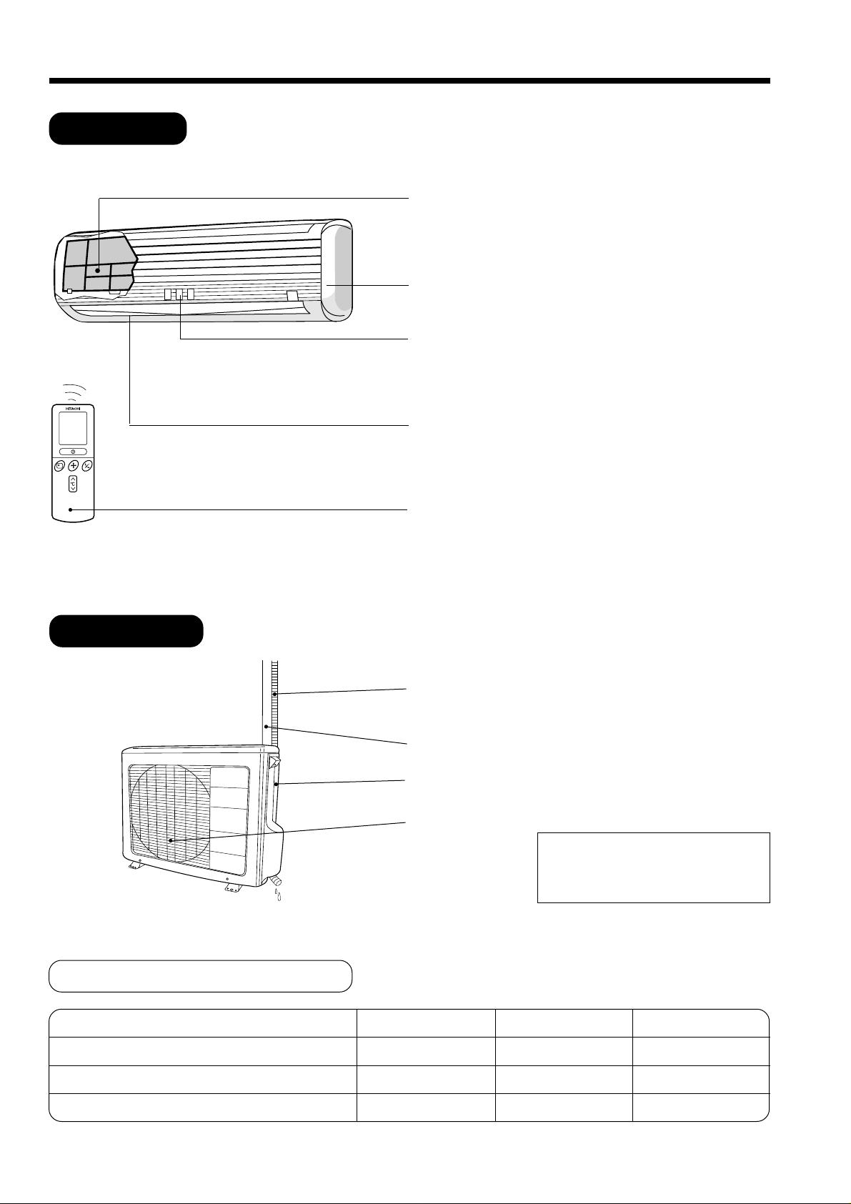
NAMES AND FUNCTIONS OF EACH PART
INDOOR UNIT
Air filter
To prevent dust from coming into the indoor unit.
(Refer page 26)
Front panel
Indoor unit indicators
Light indicator showing the operating condition.
(Refer page 11)
Horizontal deflector
(Air Outlet)
(Refer page 17)
●
Vertical deflector
OUTDOOR UNIT
Remote controller
Send out operation signal to the indoor unit. So as
to operate the whole unit.
(Refer page 12)
Drain pipe
Condensed water drain to outside.
Connecting cord and insulation pipe for piping
Air inlet (Back and Left side)
Air outlet
In relation to outdoor unit
• Even if operation stops, fan is running
for 10 to 60 seconds to reduce heat
of electric components.
MODEL NAME AND DIMENSIONS
MODEL
RAS-18CP5 / RAS-24CP5
RAC-24CP5
RAC-18CP5
WIDTH (mm)
1030
850
750
– 10 –
HEIGHT (mm)
295
650
570
DEPTH (mm)
183
298
280
Page 12
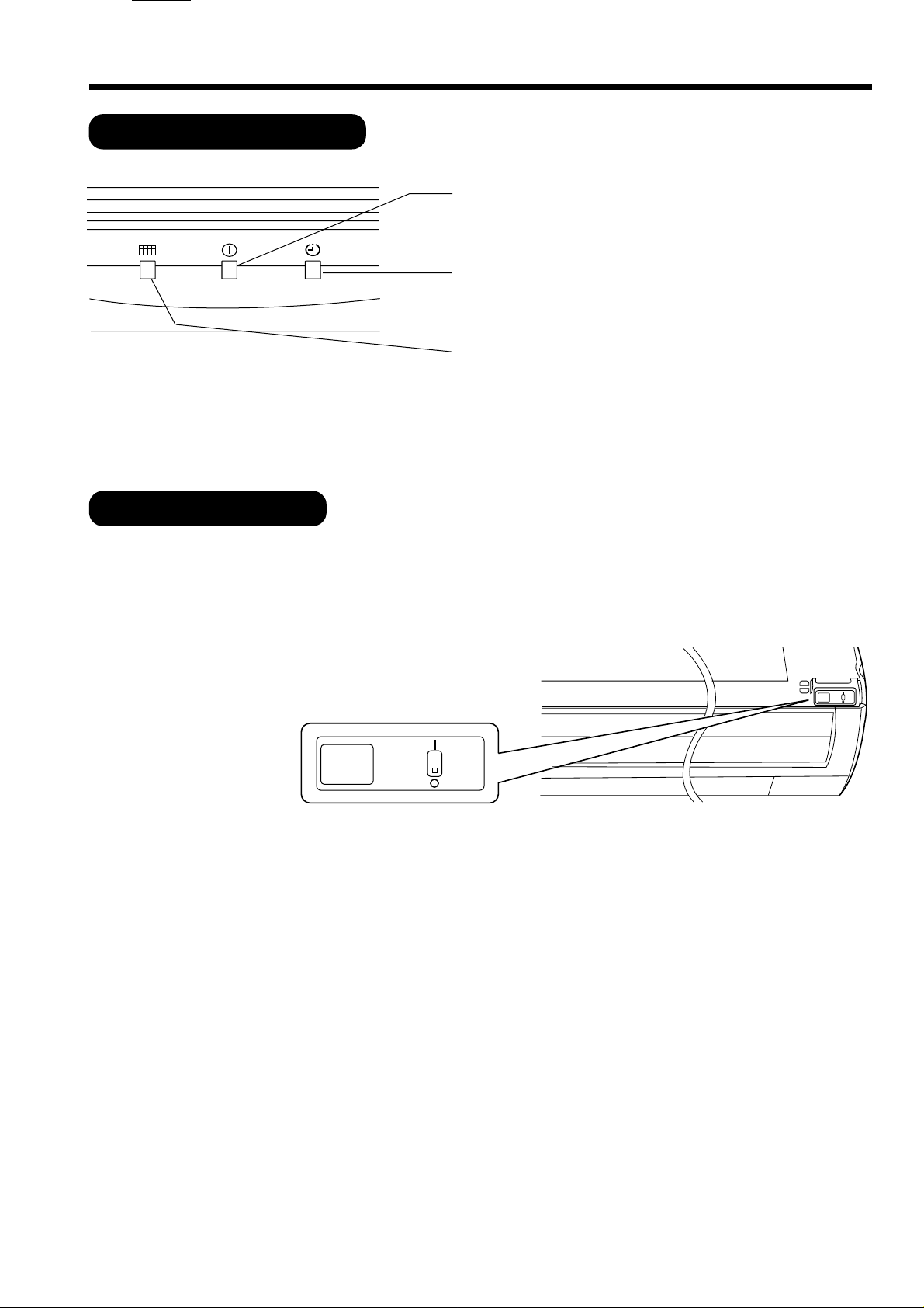
INDOOR UNIT INDICATORS
HITACHI
OPERATION INDICATOR
OPERATION LAMP
This lamp lights during operation.
TIMER LAMP
This lamp lights when the timer is working.
FILTER LAMP
When the device is operated for a total of about 100
hours, the FILTER lamp lights to indicate that it is time
to clean the filter. The lamp goes out when the power
switch set to OFF and ON again.
● This figure shows the opening condition of
front panel. Refer to page 25 in relation to
how to open or close the front panel.
AUTO
RESTART
SWITCH
AUTO
RESTART
SWITCH
AUTO RESTART SWITCH
● In the event of power failure, the air conditioner will restart automatically in the previously selected mode once
the power is restored.
● In the event of power failure during TIMER operation, the timer will be reset and the unit will begin or stop
operating under a new timer setting.
– 11 –
Page 13
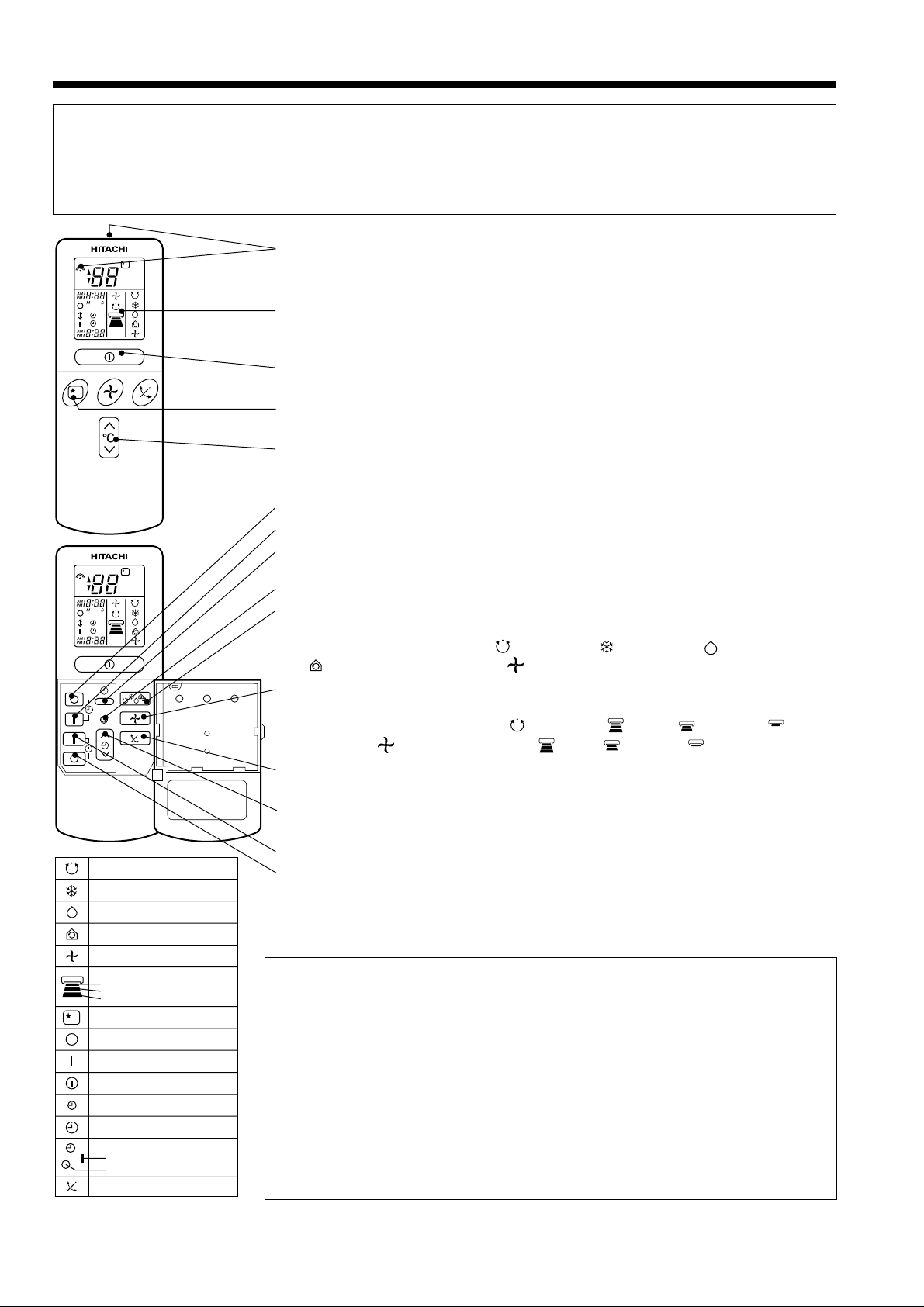
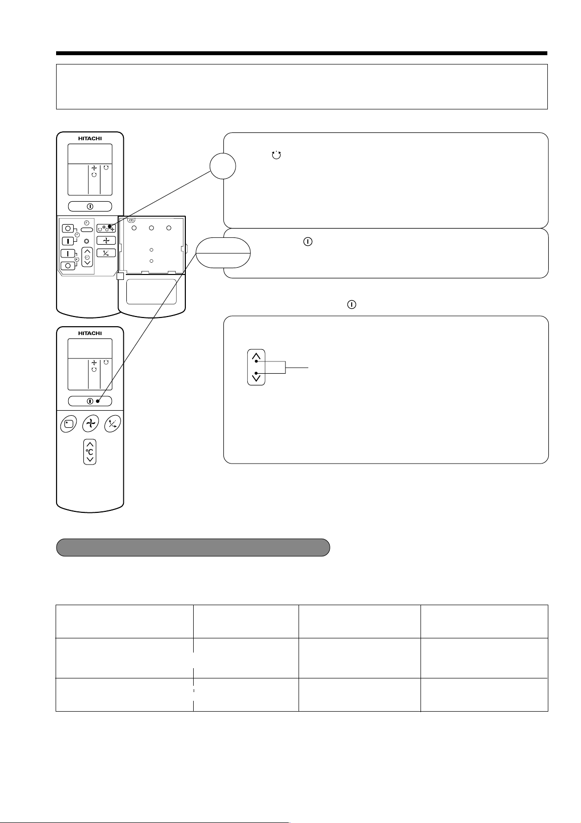
NAMES AND FUNCTIONS OF REMOTE CONTROL UNIT
REMOTE CONTROLLER
This controls the operation of the indoor unit. The range of control is about 7 meters. If indoor lighting
is controlled electronically, the range of control may be shorter.
This unit can be fixed on a wall using the fixture provided. Before fixing it, make sure the indoor unit can
be controlled from the remote controller.
●
Signal emitting window/transmission sign
CH
˚
CH
˚
RESET
AUTO
COOL
DEHUMIDIFY
CIRCULATION
FAN
FAN SPEED
LOW
MED
HI
SLEEPING
STOP (CANCEL)
START (RESERVE)
START/STOP
TIME
TIMER SET
TIMER SELECTOR
ON TIMER
OFF TIMER
AUTO SWING
Point this window toward the indoor unit when controlling it.
The transmission sign blinks when a signal is sent.
●
Display
This indicates the room temperature selected, current time, timer status,
function and intensity of circulation selected.
●
START/STOP button
Press this button to start operation. Press it again to stop operation.
●
SLEEP button
Use this button to set the sleep timer.
●
TEMPERATURE button
Use this button to raise or lower the temperature setting. (Keep pressed,
and the value will change more quickly.)
●
OFF-TIMER button Select the turn OFF time.
●
ON-TIMER button Select the turn ON time.
●
TIME button
Use this button to set and check the time and date.
●
RESET button
●
FUNCTION selector
Use this button to select the operating mode. Every time you press it,
the mode will change from (AUTO) to (COOL) to (DEHUMIDIFY)
to (CIRCULATION) and to (FAN) cyclically.
●
FAN SPEED selector
This determines the fan speed. Every time you press this button, the intensity
of circulation will change from (AUTO) to (HI) to (MED) to (LOW)
(during the (FAN) mode, from HI to MED to LOW).
●
AUTO SWING button
Controls the angle of the horizontal air deflector.
●
TIMER control
Use this button to set the timer.
●
RESERVE button Time setting reservation.
●
CANCEL button Cancel time reservation.
Precautions for Use
●
Do not put the remote controller in the following places.
●
Under direct sunlight.
●
In the vicinity of a heater.
●
Handle the remote controller carefully. Do not drop it on the floor,
and protect it from water.
●
Once the outdoor unit stops, it will not restart for about 3 minutes
(unless you turn the power switch off and on or unplug the power
cord and plug it in again).
This is to protect the device and does not indicate a failure.
●
If you press the FUNCTION selector button during operation, the
device may stop for about 3 minutes for protection.
– 12 –
Page 14
AUTOMATIC OPERATION
The device will automatically determine the mode of operation COOL, or Dehumidify, depending on the
initial room temperature. The selected mode of operation will not change when the room temperature
varies.
Press the FUNCTION selector so that the display indicates
the (AUTO) mode of operation.
1
● When AUTO has been selected, the device will
automatically determine the mode of operation COOL or
Dehumidify, depending on the initial room temperature
and outdoor temperature.
RESET
START
STOP
■ As the settings are stored in memory in the remote controller, you
Press the
Operation starts with a beep.
Press the button again to stop operation.
only have to press the
You can raise or lower the temperature setting as necessary by
maximum of 3°C.
°C
● The preset temperature and the actual room temperature may
vary somewhat depending on conditions.
● The display does not indicate the preset temperature in the
AUTO mode. If you change the setting, the indoor unit will
produce a beep.
(START/STOP) button.
(START/STOP) button next time.
Press the temperature button and the
temperature setting will change by 1°C each
time.
■ CONDITION OF AUTOMATIC OPERATION
● The selected mode of operation will not change during the operation even though the room temperature
change.
INITIAL ROOM
TEMPERATURE (APPROX.)
Over 27°C COOL
16~27°C
FUNCTION
-
-
DEHUMIDIFY
– 13 –
TEMPERATURE
SETTING
27°C
Slightly lower than the
room temperature
FAN SPEED
HIGH at start, LOW after
the preset temperature is
reached.
LOW
Page 15
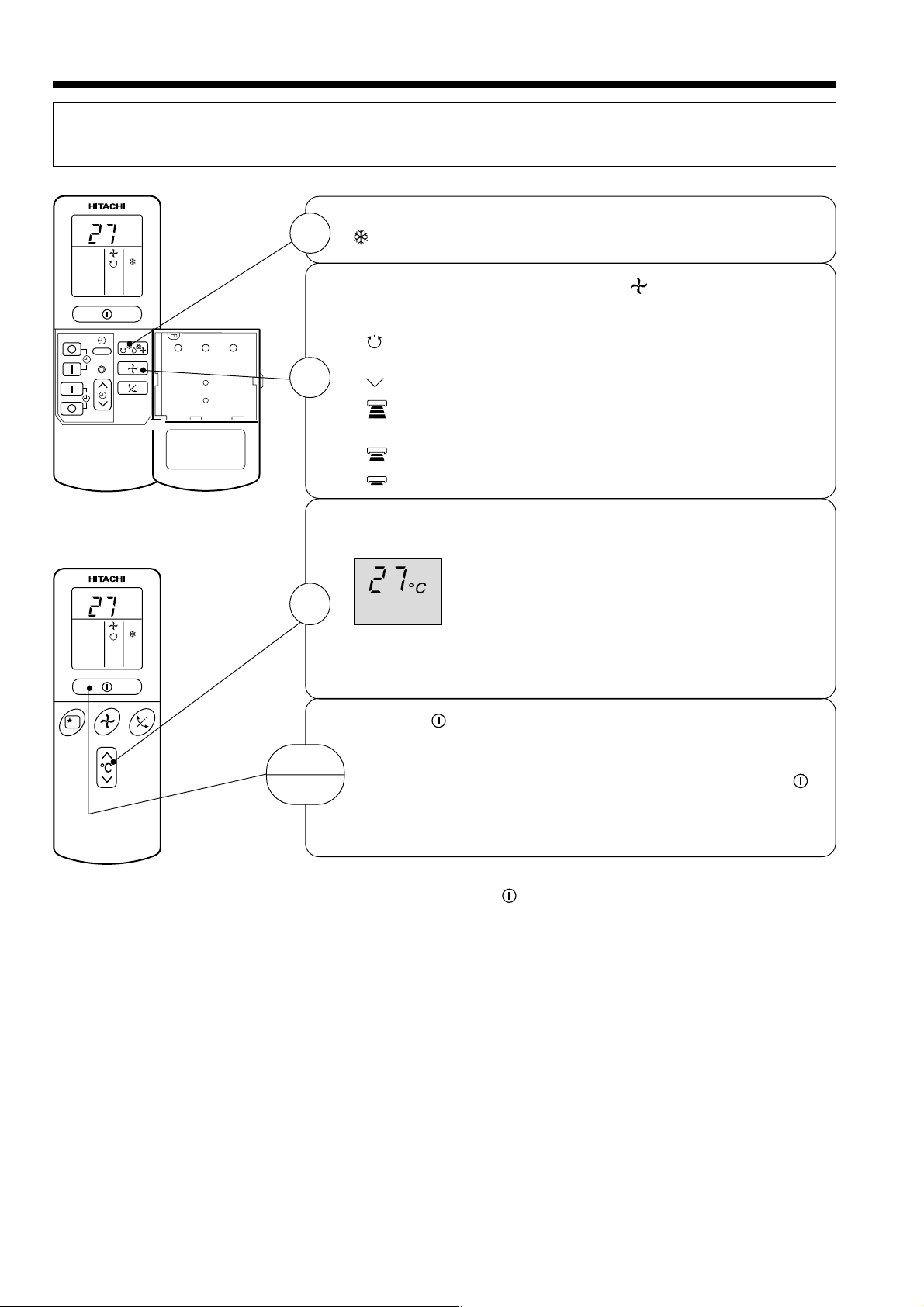
COOLING OPERATION
Use the device for cooling when the outdoor temperature is 22-42°C.
If indoor humidity is very high (80%), some dew may form on the air outlet grille of the indoor unit.
Press the FUNCTION selector so that the display indicates
C
˚
1
(COOL).
RESET
Set the desired FAN SPEED with the
(the display indicates the setting).
(AUTO): The FAN SPEED is HI at first and varies to
MED automatically when the preset temperature
2
(HI) : Economical as the room will become cool
(MED) : Quiet.
(LOW) : More quiet.
Set the desired room temperature with the TEMPERATURE
button (the display indicates the setting).
C
˚
3
START
STOP
The temperature setting and the actual room temperature may
vary some how depending on conditions.
Press the
with a beep. Press the button again to stop operation. The
cooling function does not start if the temperature setting is
higher than the current room temperature (even though the
(OPERATION) lamp lights). The cooling function will start as
soon as you set the temperature below the current room
temperature.
has been reached.
quickly.
The range of 25-28°C is recommended as the
room temperature for cooling.
If the temperature setting is 27°C, the room
temperature will be controlled at around 27°C.
(START/STOP) button. Cooling operation starts
(FAN SPEED) button
■ As the settings are stored in memory in the remote controller, you
only have to press the
– 14 –
(START/STOP) button next time.
Page 16
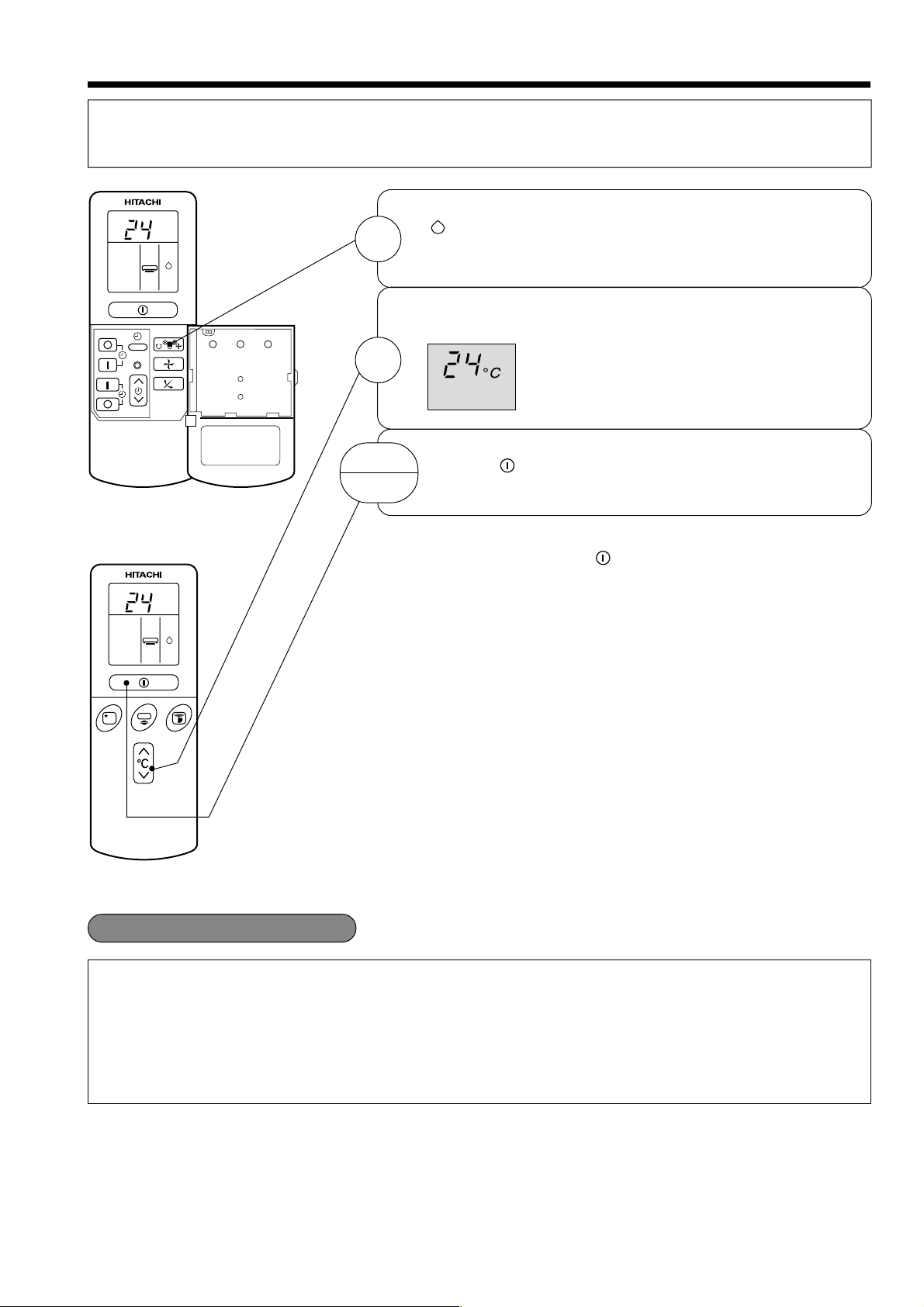
DEHUMIDIFYING OPERATION
Use the device for dehumidifying when the room temperature is over 16°C.
When it is under 15°C, the dehumidifying function will not work.
Press the FUNCTION selector so that the display indicates
(DEHUMIDIFY).
The FAN SPEED is set at LOW automatically.
The FAN SPEED button does not work.
Set the desired room temperature with the TEMPERATURE
button (the display indicates the setting).
The range of 20-26˚C is recommended as
the room temperature for dehumidifying.
RESET
C
˚
1
2
START
STOP
■ As the settings are stored in memory in the remote controller,
C
˚
Press the (START/STOP) button. Dehumidifying operation
starts with a beep. Press the button again to stop operation.
you only have to press the
(START/STOP) button next time.
■ Dehumidifying Function
When the room temperature is higher than the temperature setting: The device will dehumidify the room,
reducing the room temperature to the preset level.
When the room temperature is lower than the temperature setting: Dehumidifying will be performed at
the temperature setting slightly lower than the current room temperature, regardless of the temperature
setting. The function will stop (the indoor unit will stop emitting air) as soon as the room temperature
becomes lower than the setting temperature.
– 15 –
Page 17
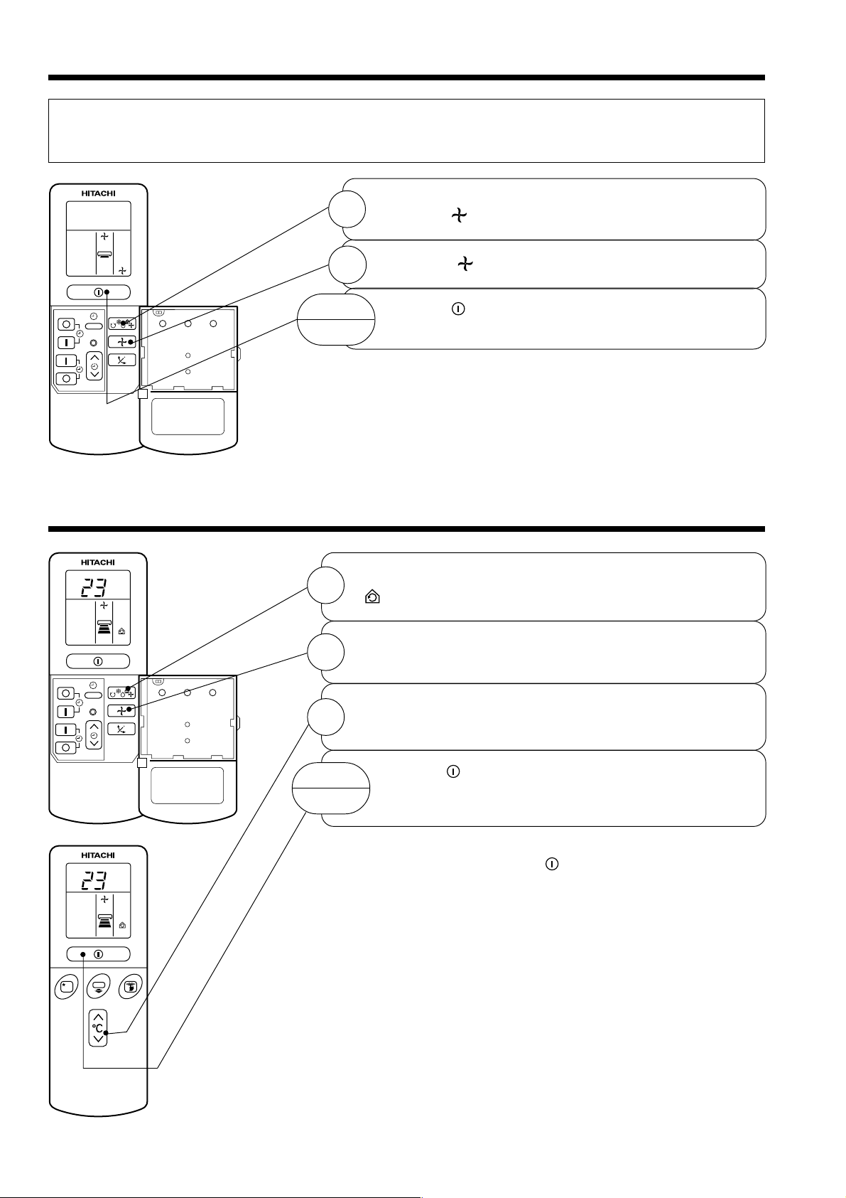
FAN OPERATION
You can use the device simply as an air circulator. Use this function to dry the interior of the indoor
unit at the end of summer.
Press the FUNCTION selector so that the display
1
indicates
(FAN).
RESET
CIRCULATION OPERATION
C
˚
2
START
STOP
1
2
Press the
Press the
with a beep. Press the button again to stop operation.
Press the FUNCTION selector so that the display indicates
(CIRCULATE).
Press the FAN SPEED button and select the desired FAN
SPEED (the display indicates your choice).
(FAN SPEED) button.
(START/STOP) button. Fan operation starts
RESET
Press the temperature control button to set to the desired
3
START
STOP
C
˚
temperature.
Press the
starts with a beep. Press the button again to stop
operation.
■ As the settings are stored in memory in the remote controller,
you only have to press the
time.
(START/STOP) button. Circulating operation
(START/STOP) button next
– 16 –
Page 18
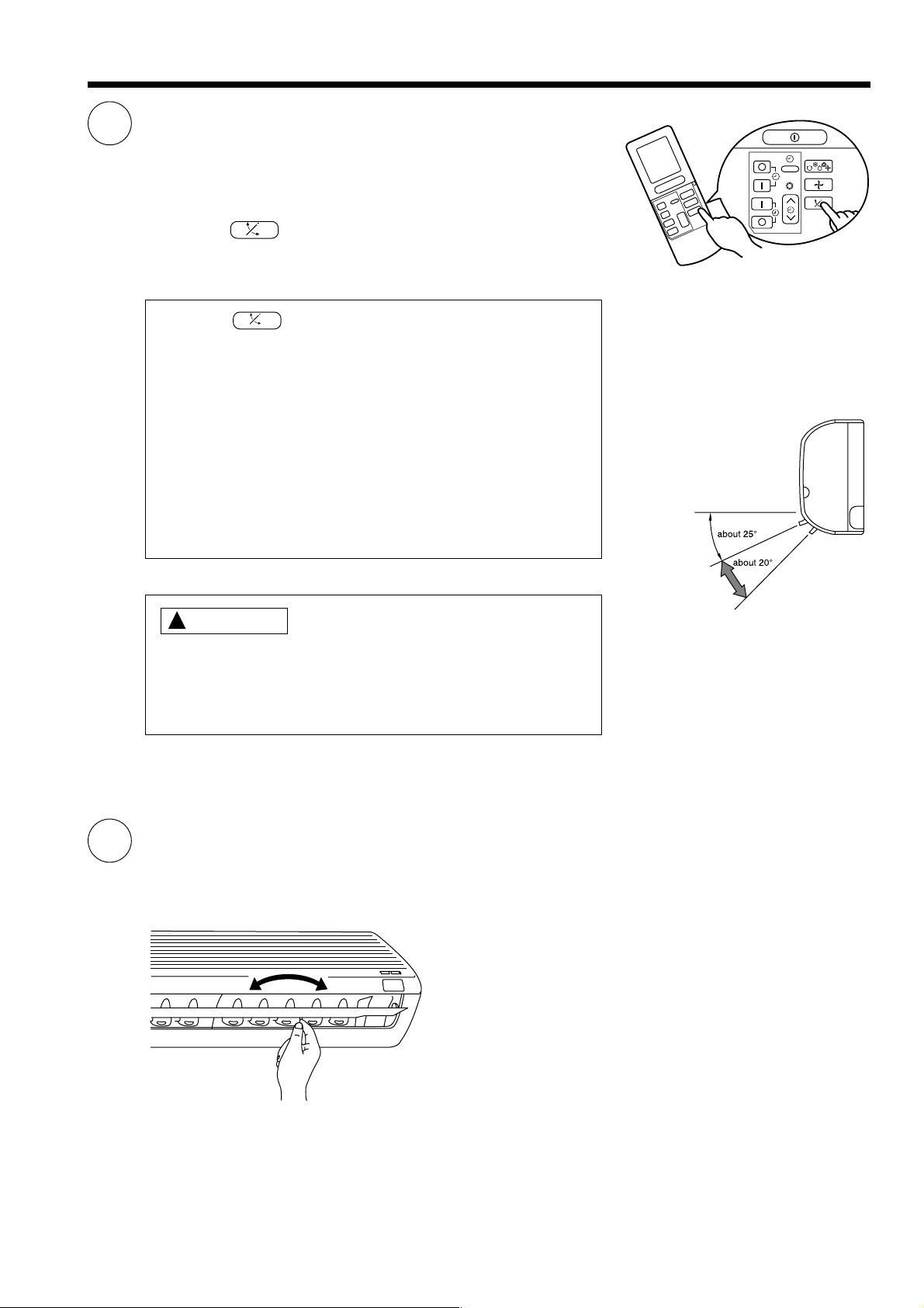
ADJUSTING THE AIR DEFLECTOR
1
Adjustment of the conditioned air in the upward and downward
directions.
The horizontal air deflector is automatically set to the proper
angle suitable for each operation. The deflector can be swung
up and down continuously and also set to the desired angle
using the “ (AUTO SWING)” button.
● If the “ (AUTO SWING)” button is pressed once,
the horizontal air deflector swings up and down. If the
button is pressed again, the deflector stops in its current
position. Several seconds (about 6 seconds) may be
required before the deflector starts to move.
● Use the horizontal air deflector within the adjusting range
shown on the right.
● When the operation is stopped, the horizontal air deflector
moves and stops at the position where the air outlet
closes.
RESET
2
CAUTION
!
● In “Cooling” operation, do not keep the horizontal air
deflector swinging for a long time. Some dew may form
on the horizontal air deflector and dew may drop.
Adjustment of the conditioned air to the left and right.
Hold the vertical air deflector as shown in the figure and adjust
the conditioned air to the left and right.
When cooling
dehumidifying
– 17 –
Page 19
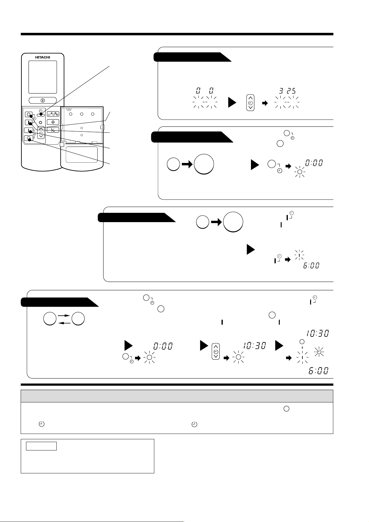
HOW TO SET THE TIMER
RESET
Time, Day, Month
TIME, DAY,
MONTH
After you change the
batteries;
(current time,
day, month)
OFF TIMER
ON TIMER
OFF-Timer
RESERVE
CANCEL
Start
You can set the device to turn off
at the present time.
ON-Timer
● The device will turn on at
the designated times.
M D
STOP
Stop
1
Set the current month and
day with the TIMER control
button.
M D
1
Press the (OFF-TIMER)
button. The (OFF) mark blinks
on the display.
1
Start
Press the (ON-TIMER)
button the (ON) mark blinks
on the display.
AM
AM
1
ON/OFF-Timer
Start Stop
● The device will turn on (off) and off
(on) at the designated times.
● The switching occurs first at the
preset time that comes earlier.
● The arrow mark appearing on the
display indicates the sequence of
switching operations.
Press the (ON-OFF)
button so that the (OFF)
mark blinks.
PM
2
Set the turn-off time
with the TIMER control
button.
Press the (RESERVE)
button.
PM
3
Press the (ON-
TIMER) button so that the
(OFF) mark lights and
the (ON) mark blinks.
PM
AM
How to Cancel Reservation
Point the signal window of the remote controller toward the indoor unit, and press the (CANCEL)
button.
The (RESERVED) sign goes out with a beep and the (TIMER) lamp turns off on the indoor unit.
NOTE
You can set only one of the OFF-timer,
ON-timer and ON/OFF-timer.
– 18 –
Page 20
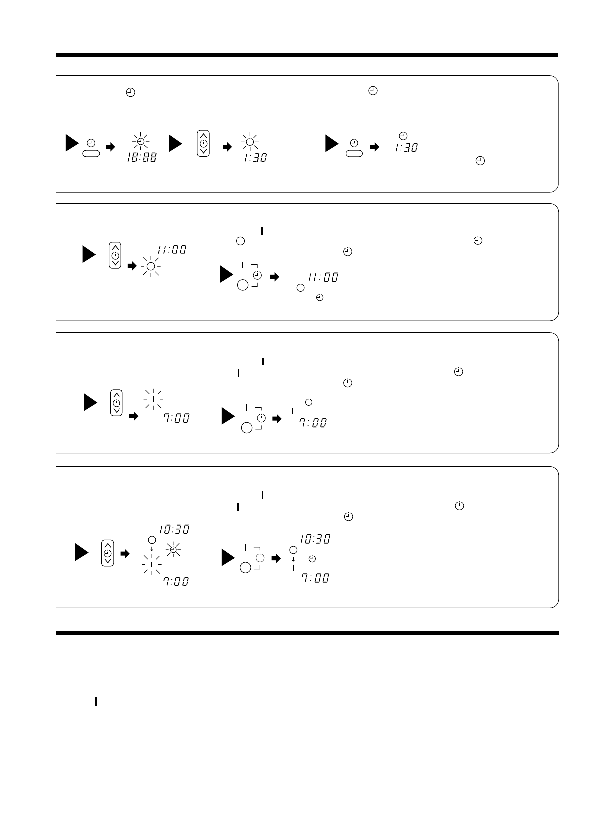
2
Press the
(TIME) button.
AM
PM PM
2
Set the turn-off time with the
TIMER control button.
3
TIMER control button.
PM
Set the current time with the
Example: The current time is 1:30 p.m.
3
Point the signal window of the remote controller toward the indoor unit, and
press the (RESERVE) button.
The (OFF) mark starts lighting instead of flashing and the sign (RESERVED)
lights. A beep occurs and the (TIMER) lamp lights on the indoor unit.
4
Press the (TIME) button again.
The time indication starts lighting
instead of flashing.
● The time indication will disappear
PM
● To check the current time setting,
automatically in 10 seconds.
press the (TIME) button twice.
The setting of the current time is
now complete.
2
Set the turn-on time with the
TIMER control button.
AM
4
Set the turn-on time with the
TIMER control button.
PM
AM
PM
The setting of turn-off time is now complete.
3
Point the signal window of the remote controller toward the indoor unit, and
press the (RESERVE) button.
The (ON) mark starts lighting instead of flashing and the (RESERVED) sign
lights. A beep occurs and the (TIMER) lamp lights on the indoor unit.
Example:
AM
5
Point the signal window of the remote controller toward the indoor unit, and
press the (RESERVE) button.
The (ON) mark starts lighting instead of flashing and the (RESERVED) sign
lights. A beep occurs and the (TIMER) lamp lights on the indoor unit.
PM
AM
The device will automatically turn on earlier so that the preset
temperature can be reached at 7:00 a.m.
The setting of the turn-on time is now complete.
Example:
The device will turn off at 10:30 p.m. and then automatically
turn on earlier so that the preset temperature can be reached
at 7:00 a.m.
The settings of the turn-on/off times are now complete.
Example: The device will turn off at 11:00p.m.
● The timer may be used in three ways: off-timer, on-timer, and ON/OFF (OFF/ON)-timer. Set
the current time at first because it serves as a reference.
● As the time settings are stored in memory in the remote controller, you only have to press
the (RESERVE) button in order to use the same settings next time.
– 19 –
Page 21

HOW TO SET THE SLEEP TIMER
Set the current time first if it is not set before (see the pages for setting the
current time). Press the (SLEEP) button, and the display changes as
shown below.
Mode
44 44
H
SLEEP
Sleep timer
Sleep Timer: The device will continue working for the designated
number of hours and then turn off.
Point the signal window of the remote controller toward the indoor
unit, and press the SLEEP button.
The timer information will be displayed on the remote controller. The
TIMER lamp lights with a beep from the indoor unit. When the sleep
timer has been set, the display indicates the turn-off time.
H
Sleep
timer
1
Set the ON-timer.
Start
1 hour 2 hours 3 hours 7 hours
The device will be turned off by the sleep
timer and turned on by on-timer.
Indication
Sleep timer off
Example: If you set 3 hours sleep
time at 11:38 p.m., the turn-off
time is 2:38 a.m.
1
2
Press the (SLEEP) button and set the sleep timer.
AM
H
AM
For heating:
In this case, the device will turn off
in 2 hours (at 1:38 a.m.) and starts
at 6:00 a.m. next morning.
How to Cancel Reservation
Point the signal window of the remote controller toward the indoor unit, and press the (CANCEL)
button.
The (RESERVED) sign goes out with a beep and the (TIMER) lamp turns off on the indoor unit.
– 20 –
Page 22

Explanation of the sleep timer
The device will control the FAN SPEED and room temperature automatically so as to be quiet and
good for people’s health.
You can set the sleep timer to turn off after 1, 2, 3 or 7 hours. The FAN SPEED and room
temperature will be controlled as shown below.
Operation with the sleep timer
Function Operation
Cooling
“ ”
controlled 2°C above the
temperature and the FAN
SPEED will be set to LOW
The room temperature will be
and
dehumidifying
“ ”
setting 1 hour after the setting
of the sleep timer.
Sleep
timer set
2 hours
later
1 hour
6 hours
later
7 hours later
3 hours later
Fan
The settings of room temperature and circulation are varied.
“ ”
NOTE
● If date or current time is not set, sleep timer can not be set.
● If you set the sleep timer after the off-, on/off- or off/on-timer has been set, the sleep timer
becomes effective instead of the off-, on/off- or off/on-timer set.
● You can not set other timer during sleep timer operation.
● The angle of horizontal air deflector shifts up automatically after three hours on sleep timer
operation.
● Fan will stop for a while if room temperature reaches setting temperature.
– 21 –
Page 23

HOW TO EXCHANGE THE BATTERIES IN THE REMOTE CONTROLLER
Remove the cover as shown in the figure and take out the
1
old batteries.
=
Install the new batteries.
2
The direction of the batteries should match the marks in the
case.
!
CAUTION
1. Do not use new and old batteries, or different kinds of batteries
together.
2. Take out the batteries when you do not use the remote controller
for 2 or 3 months.
Push and pull to the
direction of arrow
– 22 –
Page 24

THE IDEAL WAYS OF OPERATION
Suitable Room Temperature Install curtain or blinds
!
Warning
Freezing temperature
is bad for health and a
waste of electric power.
Ventilation Effective Usage Of Timer
It is possible to
reduce heat
entering the
room through
windows.
!
Caution
Do not close the room for a long period of
time. Occasionally open the door and windows
to allow the
entrance of
fresh air.
Do Not Forget To Clean The Air Filter
Dusty air filter will reduce the air volume and
the cooling efficiency. To prevent from wasting
electric energy, please clean the filter every 2
weeks.
At night, please use the “OFF or ON timer
operation mode”, together with your wake up
time in the morning. This will enable you to
enjoy a comfortable room temperature. Please
use the timer effectively.
Please Adjust Suitable Temperature
For Baby And Children
Please pay attention to the room temperature
and air flow direction when operating the unit
for baby, children and old folks who have
difficulty in movement.
– 23 –
Page 25

FOR USER’S INFORMATION
The Air Conditioner And The Heat Source In The Room
!
Caution
If the amount of heat in the room is above the cooling
capability of the air conditioner (for example: more
people entering the room, using heating equipments
and etc.), the preset room temperature cannot be
achieved.
Not Operating For A Long Time
When the indoor unit is not to be used for a long
period of time, please switch off the power from the
mains. If the power from mains remains “ON”, the
indoor unit still consumes about 8W in the operation
control circuit even if it is in “OFF” mode.
OFF
When Lightning Occurs
!
Warning
To protect the whole unit during lightning, please
stop operating the unit and remove the plug from the
socket.
Interference From Electrical Products
!
Caution
To avoid noise interference, please place the indoor
unit and its remote controller at least 1m away from
electrical products.
To prevent
interference,
place at least
1m away.
Inverter-type
fluorescent
lamp.
TV
– 24 –
Page 26

ATTACHING THE AIR CLEANSING AND DEODORIZING FILTERS
!
CAUTION
Cleaning and maintenance must be carried out only by qualified service personal. Before cleaning,
stop operation and switch off the power supply.
1
2
3
Open the front panel.
● Pull up the front panel by holding it at both sides
with both hands.
Remove the filter.
● Push upward to release the claws and pull out the
filter.
Attaching the air cleansing and deodorizing filters
to the filter.
● Attach the air cleansing and deodorizing filters to
the frame by gently compress its both sides and
release after insertion into filter frame.
Claws
(4 places)
!
CAUTION
Do not bend the air cleansing
and deodorizing filter as it may
cause damage to the structure.
4
Attach the filters.
● Attach the filters by ensuring that the surface written
“FRONT” is facing front.
● After attaching the filters, push the front panel at
three arrow portion as shown in figure and close it.
NOTE
● In case of removing the air cleansing and deodorizing filters, please follow the above procedures.
● The cooling capacity is slightly weakened and the cooling speed becomes slower when the air cleansing
and deodorizing filters are used. So, set the fan speed to "HIGH" when using it in this condition.
● Air cleansing and deodorizing filters are washable and reusable up to 20 times by using vacuum cleaner
or water rinse under running tap water. Type number for this air cleansing filter is <SPX-CFH5>. Please
use this number for ordering when you want to renew it.
● Do not operate the air conditioner without filter. Dust may enter the air conditioner and fault may occur.
– 25 –
Page 27

MAINTENANCE
!
CAUTION
Cleaning and maintenance must be carried out only by qualified service personal. Before cleaning,
stop operation and switch off the power supply.
1. AIR FILTER
Clean the air filter, as it removes dust inside the room. In case the air filter is full of dust, the air flow
will decrease and the cooling capacity will be reduced. Further, noise may occur. Be sure to clean the
filter following the procedure below.
PROCEDURE
1
2
3
Open the front panel and remove the filter
● Gently lift and remove the air cleansing and
deodorizing filter from the air filter frame.
Vacuum dust from the air filter and air cleansing
and deodorizing filter using vacuum cleaner. If
there is too much dust, rinse under running tap
water and gently brush it with soft bristle brush.
Allow filters to dry in shade.
● Re-insert the air cleansing and deodorizing
filter to the filter frame. Set the filter with
“FRONT” mark facing front, and slot them into
the original state.
● After attaching the filters, push the front panel
at three arrow portions as shown in figure
and close it.
NOTE:
● Air cleansing and deodorizing filter should be cleaned every month or sooner if noticeable loading
occurs. When used overtime, it may loose its deodorizing function. For maximum performance, it is
recommended to replace it every 3-6 months depending on application requirements.
!
CAUTION
● Do not wash with hot water at more than 40°C. The filter may shrink.
● When washing it, shake off moisture completely and dry it in the shade; do not expose it directly to
the sun. The filter may shrink.
● Do not use detergent on the air cleansing and deodorizing filter as some detergent may deteriorate
the filter electrostatic performance.
– 26 –
Page 28

2. Washable Front Panel
● Remove the front panel and wash with clean
water.
Wash it with a soft sponge.
After using neutral detergent, wash thoroughly
with clean water.
● When front panel is not removed, wipe it with
a soft dry cloth. Wipe the remote controller
thoroughly with a soft dry cloth.
● Wipe the water thoroughly.
If water remains at indicators or signal
receiver of indoor unit, it causes trouble.
Method of removing the front panel.
Be sure to hold the front panel with both hands
to detach and attach it.
Removing the Front Panel
Arm
● When the front panel is fully opened with
both hands, push the right arm to the inside
to release it, and while closing the front panel
● Move the projections of the left and right
arms into the Flanges in the unit and
securely insert them into the holes.
Attaching the Front Panel
slightly, put it out forward.
!
CAUTION
● Do not splash or direct water to the body of the unit when cleaning
it as this may cause short circuit.
● Never use hot water (above 40°C), benzine, gasoline, acid, thinner or
a brush, because they will damage the plastic surface and the coating.
Projection
Hole
Flange
– 27 –
Page 29

!
CAUTION
Cleaning and maintenance must be carried out only by qualified service personal. Before cleaning,
stop operation and switch off the power supply.
3. MAINTENANCE AT BEGINNING OF LONG OFF PERIOD
● Run the unit by setting the operation mode to
(COOL), the temperature to 32°C and the fan speed
to HI for about half a day on a fine day, and dry the
whole of the unit.
● Switch off the power plug.
REGULAR INSPECTION
PLEASE CHECK THE FOLLOWING POINTS BY QUALIFIED SERVICE PERSONAL EITHER
EVERY HALF YEARLY OR YEARLY. CONTACT YOUR SALES AGENT OR SERVICE SHOP.
1
2
3
Confirm
Is the earth line disconnected or broken?
Is the mounting frame seriously affected by rust and is the
outdoor unit tilted or unstable?
Is the plug of power line firmly plugged into the socket?
(Please ensure no loose contact between them).
– 28 –
Page 30

AFTER SALE SERVICE AND WARRANTY
WHEN ASKING FOR SERVICE, CHECK THE FOLLOWING POINTS.
CONDITION CHECK THE FOLLOWING POINTS
● Is the fuse all right?
When it does not operate
When it does not cool well
When it does not hot well
● Is the voltage extremely high or low?
● Is the circuit breaker “ON”?
● Was the air filter cleaned?
● Does sunlight fall directly on the outdoor unit?
● Is the air flow of the outdoor unit obstructed?
● Are the doors or windows opened, or is there any source of
heat in the room?
● Is the set temperature suitable?
Notes
● In quiet operation or stopping the operation, the following phenomena
may occassionally occur, but they are not abnormal for the operation.
(1) Slight flowing noise of refrigerant in the refrigerating cycle.
(2) Slight rubbing noise from the fan casing which is cooled and then
gradually warmed as operation stops.
● The odor will possibly be emitted from the room air conditioner because
the various odor, emitted by smoke, foodstuffs, cosmetics and so on,
sticks to it. So the air filter and the evaporator regularly must be cleaned
to reduce the odor.
●
Please contact your sales agent immediately if the air conditioner still fails to operate normally after the above
inspections. Inform your agent of the model of your unit, production number, date of installation. Please also
inform him regarding the fault.
●
Power supply shall be connected at the rated voltage, otherwise the unit will be broken or could not reach the
specified capacity.
Please note:
On switching on the equipment, particularly when the room light is dimmed, a slight brightness fluctuation
may occur. This is of no consequence.
The conditions of the local Power Supply Companies are to be observed.
NOTE:
If the supply cord is damaged, it must be replaced by the special cord obtainable at authorized service
parts centers.
– 29 –
Page 31

CONSTRUCTION AND DIMENSIONAL DIAGRAM
MODEL RAS-18CP5/RAS-24CP5
183
Top air suction grille
Front cover
295
About
380
350
About
View from back
(Pipe lead-out)
6.5 60
47
47
31 120.5
60 60
263 317450
158
Drain outlet
Horizontal deflectorDischarge grille
Drain hose
Hole on the wall
for ø 65mm pipe
Power cord
Connecting cable
P
47
Drain
Narrow pipe
Wide pipe
Vertical deflector
7070
Drain cap
connection port
147
56 17.5
28
47
When piping is
drawn horizontally,
exchange the drain
hose for the drain cap
6.5 60
Note:
1. Servicing space of 100mm or more is required on the left and right sides of the indoor unit and also 50mm or
more space is required above the unit
2. Insulated pipes should be used for both the narrow and wide dia. pipes.
3. Piping length is within 15m
4. Height different of the piping between the indoor unit and the outdoor unit should be within 8m.
5. Power supply cord length is about 2m
6. Connecting cord 2.5mm2 dia. x 3 is used for connection.
When power supplies to indoor Unit
Line
cord
L
N
Indoor Unit
BA
Connecting
Cord
Outdoor Unit
B
A
– 30 –
Page 32

MODEL RAC-24CP5
10464
955
26 850
79
340
2022 298
Handle
Fixing hole
Air suction
grille
Holes for anchor bolt
(2-ø12)
507 198
Notch for anchor bolt
(2-ø12 Notchs)
12
37
57
Air outlet
10
1010
320
340
More than
100
638
650
Service space
700
More than
100
More than
201
Handle
96
More than
100
169.5
MODEL RAC-18CP5
16556
28 750
852
57
10
320
340
76
570
559
195
2616 280
166
95
340
280
500
15
12
37
124
10
– 31 –
Page 33

MAIN PARTS COMPONENT
BLACK
CAPACITOR
RA
RED
INTERNAL
THERMAL FUSE
GRAY
RM
THERMOSTAT
Thermostat Specifications
MODEL RAS-18CP5 / RAS-24CP5
THERMOSTAT MODEL IC
OPERATION MODE
ON
OFF
ON
OFF
ON
OFF
TEMPERATURE
°C (°F)
INDICATION
16
INDICATION
24
INDICATION
32
FAN MOTOR
Fan Motor Specifications
MODEL RAS-18CP5 / RAS-24CP5
PHASE
RA TED VOLT AGE
RA TED FREQUENCY
– – – – –
DC8~ 35V
– – – – –
COOL
15.6 (60.1)
15.3 (59.5)
23.6 (74.5)
23.3 (73.9)
31.6 (88.9)
31.3 (88.3)
RAC-18CP5
SINGLE
220-240V
RAC-24CP5
50 Hz
OUTPUT
POLE NUMBER
CONNECTION
RESISTANCE VALUE
( )
20°C
75°C
DC8 ~ 35V
20 W
– – – – –
RED
YELLOW
5V
BLUE
– – – – –
– – – – –
M
30 W
RM = 248.5
RA = 171.3
RM = 302.2
RA = 208.3
40 W
6
RM = 127.4
RA = 122.5
RM = 154.9
RA = 149.0
– 32 –
Page 34

COMPRESSOR MOTOR
Compressor Motor Specifications
MODEL RAC-18CP5 RAC-24CP5
COMPRESSOR MODEL SHY33MC4-E SHV33YC1-E
PHASE SINGLE
RATED VOLTAGE 220 ~ 240 V
RATED FREQUENCY 50 Hz
LOCKED ROTOR CURRENT 45 A 60 A
POLE NUMBER 2
WHITE
CONNECTION
20°C
RESISTANCE VALUE
( )
(68°F)
75°C
(167°F)
EXTERNAL OVERLOAD RELAY
INTERNAL PROTECTOR
S (RED)
ORANGE
RM = 1.47
RA = 2.88
RM = 1.79
RA = 3.50
NO
YES
CAPACITOR
RM
M OR R
(ORANGE)
PROTECTOR
RA
RED
RM = 1.030
RA = 2.570
RM = 1.253
RA = 3.125
NO
YES
CAUTION
C (WHITE)
When the refrigerating cycle has been operated for a long time with the capillary tubes clogged or crushed
or with too little refrigerant, check the color of the refrigerating machine oil inside the compressor. If the
color has been changed conspicuously, replace the compressor.
CAUTION
!
RAC-18CP5/RAC-24CP5
When the Air Conditioner has been operated for a long time with the capillary tubes clogged or crushed or
with too little coolant, check the color of the refrigerant oil inside the compressor. If the color has been
changed conspicuously, replace the compressor.
– 33 –
Page 35

U
A
B
H
G
JJ
T
S
Z
2
1
N
N
P
2
1
RV
3.15A
X
B
E
D
V
M
CK
R OR V
ORG
S OR X
C OR U
RED
RED
GRY
GRY
BLK
BLK
BLK
WHT
BLU
B
A
BLU
BLU
BLU
CN4
BLK
B
A
BRN
BRN
RED
RED
CONNECTING
CORD
WHT
BLK
GRN+YEL
CN13
CN15
CN16
CN14
SWITCHING POWER P.C.B.
GRN
43
43
C1 C2 M1 M2
GRY
GRY
4 LINES
CN2
INDICATING
CN8B
CN10
RED
YEL
BLU
RED
YEL
BLU
WHT
BLK
BLU
BLU
M
M
1231234
1234
RED
BLU
BRN
BLU
GRN+YEL
CN1
TEST
HA
CONTROL P.C.B.
1
2
3
4
WHT
WHT
IVOWHT
REMOTE
CONTROLLER
WHT
BRN
RED
P.C.B.
P.C.B.
RECEIVER
7 LINES
IVO
CN11
CN11
CN2
IVO
BLK
BLK
WHT
CN12
RED
BLK
INDOOR UNIT
OUTDOOR UNIT
WIRING DIAGRAM
MODEL RAS-18CP5/RAC-18CP5
A : COMPRESSOR J : TERMINAL BOARD S : ROOM THERMISTOR
B : FAN MOTOR K : LINE CORD T : HEX THERMISTOR
C : POWER SWITCH M : STICK RELAY U : INTERNAL PROTECTOR
D : THERMAL FUSE FOR 2P TERMINAL (102°C) N : NOISE FILTER V : VARISTOR
E : THERMAL FUSE FOR P.C.B. (96°C) P : POWER RELAY X : FUSE
G : 50 µF CAPACITOR R : SURGE ABSORBER Z : AUTO SWEEP MOTOR
H : 2.5 µF CAPACITOR
BLU : BLUE YEL : YELLOW BRN : BROWN WHT: WHITE
GRY : GRAY ORN : ORANGE GRN : GREEN RED : RED
BLK : BLACK PNK : PINK VIO : VIOLET IVO : IVORY
– 34 –
Page 36

U
A
B
H
G
JJ
T
S
Z
2
1
N
N
P
2
1
RV
3.15A
X
B
E
D
V
M
CK
R OR V
ORG
S OR X
C OR U
RED
RED
GRY
GRY
BLK
BLK
BLK
WHT
BLU
B
A
BLU
BLU
BLU
CN4
BLK
B
A
BRN
BRN
RED
RED
CONNECTING
CORD
WHT
BLK
GRN+YEL
CN13
CN15
CN16
CN14
SWITCHING POWER P.C.B.
GRN
43
43
C1 C2 M1 M2
GRY
GRY
4 LINES
CN2
INDICATING
CN8B
CN10
RED
YEL
BLU
RED
YEL
BLU
WHT
BLK
BLU
BLU
M
M
1231234
1234
RED
BLU
BRN
BLU
GRN+YEL
CN1
TEST
HA
CONTROL P.C.B.
1
2
3
4
WHT
WHT
IVOWHT
REMOTE
CONTROLLER
WHT
BRN
RED
P.C.B.
P.C.B.
RECEIVER
7 LINES
IVO
CN11
CN11
CN2
IVO
BLK
BLK
WHT
CN12
RED
BLK
INDOOR UNIT
OUTDOOR UNIT
WIRING DIAGRAM
A : COMPRESSOR J : TERMINAL BOARD S : ROOM THERMISTOR
B : FAN MOTOR K : LINE CORD T : HEX THERMISTOR
C : POWER SWITCH M : STICK RELAY U : INTERNAL PROTECTOR
MODEL RAS-24CP5/RAC-24CP5
D : THERMAL FUSE FOR 2P TERMINAL (102°C) N : NOISE FILTER V : VARISTOR
E : THERMAL FUSE FOR P.C.B. (96°C) P : POWER RELAY X : FUSE
G : 60 µF CAPACITOR R : SURGE ABSORBER Z : AUTO SWEEP MOTOR
H : 2.5 µF CAPACITOR
BLU : BLUE YEL : YELLOW BRN : BROWN WHT: WHITE
GRY : GRAY ORN : ORANGE GRN : GREEN RED : RED
– 35 –
BLK : BLACK PNK : PINK VIO : VIOLET IVO : IVORY
Page 37

CIRCUIT DIAGRAM
Remote Control
Key matrix table
1
SEG5
2
SEG0
3
SEG1
4
SEG2
5
SEG3
SEG4
6
7
SEG5
8
SEG6
9
SEG7
10
COM3
11
COM2
12
COM1
13
COM0
14
SEG14
15
SEG13
16
SEG12
17
SEG11
18
SEG13
19
SEG9
20
SEG8
D3
RB425D(1/2)
C8
50v/1u
LCD 1
K 1
K2K3
K4
K5
P10
P11
K6
K7 K8
K8 K10
K11K12
SEG20
SEG19
SEG18
SEG17
SEG16
SEG21
SEG24
SEG25
SEG26
SEG27
SEG28
P12
40
39
38
37
36
35
34
33
32
31
30
29
NC
28
NC
27
NC
26
NC
25
NC
24
NC
23
NC
22
NC
NC
21
K13 K14
K15 K16
K17
K18
D0
D1
D2
D3
65
66
67
68
69
70
71
72
73
74
75
76
77
78
79
80
64
SEG20
SEG21
SEG22
SEG23
SEG24
SEG25
SEG26
SEG27
SEG28
SEG29
SEG30
SEG31
SEG32
SEG33
SEG34
SEG35
1
62
63
SEG19
SEG18
P41
P40
3
2
R1
100k
60
61
SEG17
SEG16
P42
P43
5
4
59
58
57
56
54
SEG14
SEG15
IC 1
SEG13
SEG12
55
SEG11
SEG10
SEG9
53
52
51
SEG8
SEG7
50
49
SEG5
SEG6
M3455OM6A-510FP
D2
P00
6
P01
7
P02
8
P03
9
P10
10
P11
11
P12
12
P13
13
D0
14
D1
15
16
48 47
SEG4
D3
D4
17 18
46
SEG2
SEG3
D5
19
45
44
SEG0
SEG1
D7
D6
20
21
SW1
SW-187-2P
Input
P10
P11
P12
43
42
SEG42
SEG43
D9
D8
22
23
Output
Door open
Door shut
Door open
Door shut –
Door open
Door shut
41
SEG41
SEG40
40
P30
P31
39
VL C2
VL C3
XC IN
XC OUT
VDD
VSS
X OUT
X IN
RESET
CARR
P23
P22
P21
P20
BEEP
24
38
37
36
35
34
33
32
31
30
29
28
27
26
25
R2
100k
NCVL C1
D0 D1
Start/Stop
Operation selection
Start/Stop Super silent cooling
On timer
Hour up
Room temperature up
Off timer –
Sleep –
D1 D2
EL-1L7
R6
R7
R3
100k
24(1/8W)
R5
330
P
R4
100k
Q1
2SC3443
or 2SC2982
D2D1
R8
R6 R9
R9
R10
12M
D2
Fan speed selection
–
Hour down
Room temperature down
Reservation
–
D3
RB425D
(1/2)
X1
K19
910kHz
C9
105
Automatic swing
•
Day
Super cooling
R11
150k
X2
32.768
kHz
C6
104
D3
–
present time
Cancel
–
R14
220k
R13
220K
104
C7
R15
100k
R16
100k
C1
334
C2
220p
C3
220p
C4
18p
C5
22p
– 37 –
R12
220k
Page 38

10 16 D(VX) R
RD(VX)1610
C403
C402
H
2
± 5%
2.0K
R914
A
1/6W
± 5%
0R509
NOTES:
1. THE COMPONENT WITH A "H" MARK ON THE LEFT
OF THE TABLE ARE BELONG TO INDICATING BOARD.
2. THE DEFINATION OF MOUNTING FORM
a) C --- SURFACE MOUNT (SMT)
b) H --- HAND INSERTION
c) R --- RADIAL
d) A --- AXIAL
3. THE DEFINATION OF TYPE OF CAPACITOR
a) F --- FILM
b) C --- CERAMIC
c) D --- ELECTROLYTIC
AA1A4M
AA1A4M
H
SIN-21T-1.8S
BLUE WIRE
A
1/6W
± 5%
10k
1kR321
A
1/6W
± 5%
1k
SWITCHING POWER SUPPLY
SWITCHING POWER SUPPLY
WHITE
H
H
WHITE
B2B-XH-A (TOP ENTRY)
B2P3-VH (TOP ENTRY)
A
1/6W
± 5%2K
R714
AD904 RICP-2.0ATICP2
HGLASS CAPSULE
3.15A
FUSE
VARISTOR1
CN10
CN8B
±
20%
250.1
RF500.1C106
1000P RC50
C710
R
R0.047 C25
0.047 C25
0.1
0.1
0.1
R
R
R
R
C50C401
C381
C361
50C321
C
C
50
50
C302
C301
C
0.1
DC450
C
0.01HAC250
0.01 AC400
AC300
±
20%
1000P
1000P
C212 100
DH
C211
AC250C210
H
0.01
C
CH
H
H
C207 AC250
C206
C205
AC250
C
F
33
TYPE
VOLTAGE
(V)
CAPACITANCE
(F)
SYMBOL
CAPACITOR
MOUNTING
FORM
RC25
6.3
C512
C511
C501
RC50
0.1
0.1
0.082 AC300
25 C0.1
5068
C101 50
D(PF)
C102
C103
C104
C105
10
C107
C108
2550C
C
C109
150
H
R
R
R
R
R
MOUNTING
FORM
SYMBOL
CAPACITANCE
(F)
VOLTAGE
(V)
TYPE
µ
µ
µ
µ
µ
µ
µ
µ
µ
µ
µ
µ
µ
µ
µ
µ
µ
220
50
D(VR)
220
1000P
0.047
1000P
R
R
R
D(PF)
D(PF)
C
C901
50
C902
H150
D(PF)
25 C0.1 R
C208 0.047
FH
HC
C209
C621 47
16
D(MF)
H
C601
CR
R
D(VX)
HZ5.1B-J AZD701
THERM-FUSE (P.C.B)
H
WHITEXH-3P (TOP ENTRY)
CN4
SYMBOL
MODEL NO.
MOUNTING
FORM
SIN-21T-1.8S
BROWN WIRE
XH-4P (TOP ENTRY)
WIRES
SIN-21T-1.8S
SIN-21T-1.8S
SIN-21T-1.8S
H
H
H
RED WIRE
BLACK WIRE
WHITE WIRE
H
1.5A
H ,
450 HL901
SSSS9AE
A1SS-120D401
A1SS-120D701
D303 1SS-120 A
A1SS-120D302
A1SS-120D301
MODEL NO.SYMBOL
MOUNTING
FORM
DIODE
A1SS-120D304
DB201 D3SB60 H
H
H
H
TEMPOPARY
SWITCH (SW1)
INFRARED
RECEIVER
EF0EC8004A
450NR-12D
OSC1
SURGE
ABSORBER
MODEL NO.
SYMBOL
OTHERS
450NR-12D
FUSE
RESISTOR
BUZZER
VARISTOR2
MOUNTING
FORM
H
H
H
H
H
ARF25S
DSA-362MA-05
PKM13EPY
G4A-RY-200
OUTDOOR FAN
RELAY
H
REVERSING VALVE
RELAY
STICK RELAY
G4A-RY-200
H
POWER RELAY
MODEL NO.
SYMBOL
MOUNTING
FORM
RELAYS
H
H
H
H
H
H
MOUNTING
FORM
XH-3P (TOP ENTRY) WHITE
CN1
MODEL NO.SYMBOL
COLOR
CONNECTORS
REMARKS
THERM-FUSE (2PTERMINAL)
CN3
CN12
VH-4P (TOP ENTRY) WHITE ROOM HEX. THERMISTOR
CN13
BNH-6P (SIDE ENTRY) WHITE STEPPING MOTOR
CN14
WHITE HA TERMINAL
CN15
PH-4P (SIDE ENTRY) EEPROM
CN16
ZR-3P (SIDE ENTRY) TEST PIN
H
H
H
H
AX-3T2/AX-3T3 H
ULN2003AN
S24C01BDP
TL5001CP
MC7805CT
IC1
IC301
IC701
REG1
REG2
MODEL NO.
SYMBOL
MOUNTING
FORM
ZENER DIODE
MODEL NO.
SYMBOL
MOUNTING
FORM
TRANSISTOR
MODEL NO.
SYMBOL
MOUNTING
FORM
ICs
R
R
2SC458CT
Q511
AA1A4M
Q301
WHITE
G5N-RELAY
G5N-RELAYHH
BLACKVH-2P (3P, TOP ENTRY)
H
REVERSING VALVE &
OUTDOOR FAN RELAY
SU16V-10035 H
NOISE
FILTER
D902 A
A
ZD102
RQ512
2SA673CT
Q901
2SJ326
H
R
ZD101 A
SBX8035-F
RICP1
IC PROTECTOR
MOUNTING
FORM
SYMBOL
MODEL NO.
ICP-0.6AT
L101 H
INDUCTOR
MOUNTING
FORM
SYMBOL
RATED VALUE.
82 1.3A
H ,
L102
H ,
560 0.6A H
ZD511 HZ7B2 A
AD102 D1NL40
H
H
LD721
LD723
LD725
YELLOW
RED
GREEN
SEL6914A
SEL6214S
SEL6414E
R
ESD172306
SERVICE
SWITCH
R
RATED VALUE.
SYMBOL
MOUNTING
FORM
LED
AHZ30-2
HZ24-3
CN2
ZR-4P (TOP ENTRY)
CN11
ZR-7P (TOP ENTRY) IVORY
IVORY
IVORY
H
H
RECEIVER BOARD
INDICATING BOARD
H
EARTH (GREEN)
SIN-41T-2.4S
H
Q302
Q303 R
2SA1757F
2SC1214CTZ
H
R
Q903
Q904
R
ZD100 HZ24-3 A
A
1/6W
1/6W
1/6W
1/6W
1/6W
A
A
A
A
A
A
1/6W
A
A
1/6W
A
A
A
A
A
A
A
A
A
A
A
A
A
A
A
A
A
H
A
A
A
A
A
A
A
A
A
A
1/6W
1/6W
1/6W
1/6W
1/6W
1/6W
1/6W
1/6W
1/6W
1/6W
1/6W
1/6W
1/6W
1/6W
1/6W
1/6W
± 5%
220K
R109
R108
2.2K
± 5%
1/6W
1/4W
± 5%
330
R107
R106
330
± 5%
1/4W
1/4W
± 5%
470
R105
1/4W
± 5%
5.6K
R100
± 5%
1/6W
± 5%
130K
1/6W
± 2%
3K
1/6W
± 2%
33K
1/6W
± 5%
120K
± 5%
± 5%
± 5%
± 5%
± 5%
± 5%
± 5%
± 5%
FORM
± 5%
FORMFORM
± 5%
± 5%
± 5%
± 5%
± 5%
POWERTOLERANCERESISTANCESYMBOL
RESISTOR
SYMBOL RESISTANCE TOLERANCE POWER SYMBOL RESISTANCE TOLERANCE POWER
R205
R206
± 5%
1/6W
± 5%
± 5%
± 1%
± 5%
± 1%
± 5%
± 2%
± 5%
± 5%
R101
R102
R103
R104
± 5%
560K
7W
± 5%
1/2W
7.5
± 5%
± 5%
± 5%
± 5%
± 5%
± 5%
1/6W
1/6W
1/6W
1/6W
1/6W
1/6W
A
A
A
A
A
A
A
A
A
A
A
1/6W
1/6W
1/6W
1/6W
1/6W
± 5%
± 5%
± 5%
± 5%
± 5%
± 5%
1/6W
A
R932
R931
R930
R920
R919
R917
R916
R913
R906
SYMBOL RESISTANCE TOLERANCE POWER
R801
3.3K
± 5%
FORM
R721
R723
R725
300
± 5%
± 5%
240
240
± 5%
R911
1/6W
± 5%
± 5%2.0K
2
3.3K
± 5%
± 5%3.3K
20K
± 1%
2.21K ± 1%
± 1%
1K
8.25K ± 1%
5.1K
± 5%
A
A
A
A
A
A
A
1/6W
1/6W
1/6W
1/6W
1/6W
1/6W
1/6W
A
1/6W
A
A
1/6W
A
A
1/6W
1/6W
H
A
1W
± 5%
0.2
R610
R601
R603
R606
R607
R608
10K
10K
1K
R609 1K 1/6W
10K
5.1K
10K
R602
R604
R605
10K
1K
± 5%
± 5%
± 5%
1/6W
1/6W
A
A
10K
1/6W
A
± 5%
1/6W
A
1K
R621
47
R622
A
± 5%
R712
R713
1K
2K
1/6W
1/6W
R303
R304
R305
R306
R307
390
390
390
5.1k
390
5.1K
R302
R313 10k
10k
10k
10k
10k
R314
R315
R316
R317
10k
10k
R318
R319
R320
R331
R332 10k
R361
R362
12.7k
1k
R381 18k
R382
R383 2.4k
1k
R404
R405
10k
1k
1k
R511
R512
R513
R514
R515
2.7k
5.1k
10k
5.1k
3k
R510 1M
RRRR
R
R
D2S6M
300
ISS131
YELLOW WIRE
H
H
RED WIRE
SIN-21T-1.8S
SIN-21T-1.8S
µ
µ
µ
µ
µ
µ
µ
µ
µ
µ
µ
µ
µ
µ
PRINTED WIRING BOARD LOCATION DIAGRAM
MODEL RAS-18CP5/RAS-24CP5
GND
CN1
(XH-3P)
WHITE
CN4
(XH-3P)
WHITE
HEAT EXCHANGER
THERMISTOR
RESISTANCE: 10K ohms ±3% (25 C)
B-CONSTANT: 3950K ±2% (B25/50)
ROOM TEMPERATURE
THERMISTOR
RESISTANCE: 10K ohms ±2% (25 C)
B-CONSTANT: 3950K ±2% (B25/50)
OPERATION LAMP
RECEIVER BOARD
(R-BOARD)
V
DD
RECEIVER
UNIT
R621
VOUT
C621
+
-
CN10
(XH-2P)
WHITE
THERM-FUSE FOR
2PTERMINAL
THERM-FUSE FOR
INDICATION BOARD
(H-BOARD)
FILTER LAMP
TIMER LAMP
LD723
LD721
LD725
(ZR-7P)
R622
15A
15A
10A
NORMAL
NORMAL
TEMPORARY
OPERATION
CURRENT
SELECTOR
TEMPORARY
OPERATION
SW1
SERVICE SWITCH
SWITCHING POWER BOARD
1
2W
2.2K
3
CN15
(PH-4P)
WHITE
CN12
(VH-4P)
WHITE
BLACK
BLACK
CN16
(ZR-3P)
IVORY
TEST PIN
CN2
(ZR-4P)
1
2
3
4
CN11
5
6
2
3
4
7
11
200V
10A
50V
220 F
3
1
3
1
4
3
2
1
GRAY
4
GRAY
3
2
1
1
2
3
CN2
(ZR-4P)
1
2
3
4
CN11
(ZR-7P)
5
6
3
2
4
7
200V
1A
250V
0.0022 F
JW1
0V
5V
0V
R713
ZD701
0V
0.047 F
HZ5B1
1/4W
0.01 F
1/6W 3.5K
1/6W 1K
2W 150
2W
150
+
25V
120 F
2200pF
1KV
70V 0.15A
50V
0.5A
HZ7B1L
220 F
50V
800V
1A
70V 0.15A
70V
0.15A
R307
R304
IC301/IC302
(E2PROM)
134
5V
D401
0V
R405
R404
12V
R714
L (BROWN)
N (BLUE)
E (GREEN&YELLOW)
1/4W 470K
1/4W 470K
3W 120
25V
0.7A
R303
R306
56827
+
800V
-
3A
5V
C302
C301
0V
R383
R362
R382
R361
R381
0V
M-BOARD
POWER-SW
2
1
3
RED
4
BLUE
1
450V,2.2 F
3
BLK
5V
CN8B
(VH-2P)
WHITE
GREEN
BRN
RED
NOISE FILTER1
D301
D304
0V
D302
D303
Q301
0V
C381
C361
0V
D306
0V
5V
D305
12V
5V
+
0V
+
-
C511
RESET
R721
R725
R723
R514
R513
Q511
Q512
R511R512
ZD511
0V
12V
BZ1
B.Z
R801
Q302
0V
R206
D904
0V
C321
+
C403
C402
0V
R515
0V
C212
L101
R930
R932
5V
C213
R906
R931
OSC1
R712
VARISTOR 1
SURGE
ABSORBER
(D3SB60)
DB201
35V
+
C101
5V
R302
R305
R313
R314
R315
R316
R331
R332
C401
R317
R509
C512
C710
R318
R319
R320
R321
C501
ICP1
2
10
11
12
13
14
15
16
17
18
19
20
21
22
23
24
R510
25
26
27
28
29
30
31
32
3.15A
FUSE
NOISE FILTER2
VCC
1
P9 0
P9 1
3
P9 2
4
P9 3
5
P9 4
6
P9 5
7
P9 6
8
P9 7
9
AV CC
AN0
AN1
AN2
AN3
AN4
AN5
AN6
AN7
AVSS
TEST
V
RES
IRQ
TM0E
VARISTOR 2
C203 C202
R100ZD100
+
-
C109
ICP2
PWM O/P
SDA
SCL
NO USE
NO USE
NO USE
HEX. TEMP
RANGE SELECTION
NO USE
EEPROM
SELECTION
ROOM TH.
HEX. TH.
FAST FEED
TEST INDICATION
MODE
NO USE
PWM VOLTAGE
FEEDBACK
INDOOR FAN
OVER-CURRENT
2X
1X
SS
1OSC
2OSC
REMOCON I/P
0
NO USE
1IRQ
SINGLE/MULTI
4IRQ
BUZZER
CURRENT TRANS
6P1
HA O/P
7P4
C207 C206
C201 C200
C108
R101
R104
R916
IC1
EEPROM
R205
C205
2
REG1
6
7
5
R911
R917
LOUVER
CCW
FAN
REVERSING VALVE R.
OUTDOOR FAN RELAY
AMAND
REMOCON SELECTION
ZD101
R107 R106
1
4
3
8
Q903
Q904
FAN LO (MED)
OUTPUT
FAN S (LOW)
POWER RELAY
STICK RELAY
ABNORMAL
FAN CURRENT
AUTO RESTART
REMOCON ID
TEST INDICAT.
SELECTION
FORCED COOL
COOL/DEHUM.
COMP. OPER.
LED OUTPUT
FAN MOTOR
DRIVER
R914
R913
NO USE
NO USE
NO USE
NO USE
HEATER
FAN HI
NICE TEMP.
CANCEL
HA I/P
DASH
FILTER/
POWERFUL
TIMER
OPERATION
DEHUMIDIFY
7P7
6P7
5P7
4P7
B
3P7
A
2P7
B
1P7
A
P70
P67
P66
P65
P64
P63
P62
P61
P60
P17
X2
P57
X1
P56
P55
P54
P53
P52
1P5
0P5
0P4
1P4
2P4
3P4
4P4
5P4
6P4
POWER RELAY
43
STICK RELAY
POWER SUPPLY
L102
Q901
R105
D102
C106R108
R109
C105
5V
64
63
62
61
60
59
58
57
56
55
54
53
52
51
50
49
48
R601
47
R602
46
45
44
43
42
41
40
39
38
37
36
35
34
33
R603
R607
C601
R610
43
+
R102R103
C102
L901
D902
REMOCON ID
ID1
(A/B SELECTION)
R604
R605
R606
R608
R609
0V
ZD102
+
IC701
7
6
5
4
3
2
1
I
REG2
C104
C901
12V
9
8
0V
REVERSING VALVE RELAY
2
OUTDOOR FAN RELAY
O
+
-
C107
G
R919
R920
10
11
12
REVERSING VALVE
13
OUTDOOR FAN RELAY
14
POWER RELAY
15
STICK RELAY
16
SERVICE SW
0V
C103
5V
C902
D701
Q303
0V
COOL
NORMAL
3
32
12V
5V
0V
RED
YELLOW
BLUE
12V
12V
5V
0V
WHITE
BLACK
RED
1
BROWN
3
CN3
(VH-2P)
BLACK
CN13
(BNH-6P)
WHITE
5
4
3
2
1
CN14
(XH-4P)
WHITE
C1
1
C2
2
M1
3
M2
4
RED
YELLOW
BLUE
M
STEPPING
MOTOR
HA
TERMINAL
BOARD
B
A
D
C
INDOOR DC
FAN MOTOR
M
– 39 –
Page 39

BLOCK DIAGRAM
MODEL RAS-18CP5/RAC-18CP5
RAS-24CP5/RAC-24CP5
– 41 –
INDOOR UNIT
POWER SUPPLY
WIRELESS REMOTE
CONTROLLER
ROOM TEMPERATURE
THERMISTOR
HEAT EXCHANGER
THERMISTOR
DC FAN MOTOR
OPERATION CIRCUIT
WIRELESS RECEIVING CIRCUIT
POWER RELAY
STICK RELAY
INDOOR
FM
FAN MOTOR
BUZZER CIRCUIT
MICROCOMPUTER
OUTDOOR UNIT
M
FM
RELAY
INDICATION
LAMP
COMPRESSOR
OUTDOOR
FAN MOTOR
POWER RELAY
STICK RELAY
OPERATION
TIMER
FILTER
INITIALIZING
CIRCUIT
RESET
CIRCUIT
(AX-3T3)
MICROCOMPUTER
CLOCK CIRCUIT
AUTO SWEEP MOTOR 1
M
Page 40

On / Off switch
Fan Speed
Stick relay
ON / OFF switchON / OFF switch
Operation lampOperation lamp
Operation and stop are repeated independent of timer reservationsOperation and stop are repeated independent of timer reservations
ON / OFF switchON / OFF switch
ReservationReservation
CancelCancel
Operation lampOperation lamp
Timer lampTimer lamp
Timer memoryTimer memory
(OFF timer during stop)(OFF timer during stop) (Cancel)(Cancel)
(Change of the reservation time)(Change of the reservation time)
ON / OFF switchON / OFF switch
ReservationReservation
CancelCancel
Operation lampOperation lamp
Timer lampTimer lamp
Timer memoryTimer memory
(ON timer during operation)(ON timer during operation)
(Cancel)(Cancel)
(Change of the reservation time)(Change of the reservation time)
ON / OFF switchON / OFF switch
ReservationReservation
CancelCancel
Operation lampOperation lamp
Timer lampTimer lamp
Timer memoryTimer memory
(OFF ON timer)(OFF ON timer) (ON OFF timer)(ON OFF timer)
(ON OFF timer during operation)(ON OFF timer during operation)
(OFF ON timer during stop)(OFF ON timer during stop)
PM1:00 PM3:00 PM5:00PM1:00 PM3:00 PM5:00
PM1:00 PM3:00 PM5:00PM1:00 PM3:00 PM5:00 PM1:00 PM3:00 PM5:00PM1:00 PM3:00 PM5:00 PM1:00 PM3:00 PM5:00PM1:00 PM3:00 PM5:00
BASIC MODE
+3
+2
+1
Set temperature
ON / OFF Switch
Fan Speed H
Fan Speed M
Fan
Speed
Power
relay
Stick relay
Operation lamp
H L M L M H L
L M M
2 sec
2 sec
2 sec
2 sec
+3+3
+2+2
+1+1
-1
-2
-3
Set temperatureSet temperature
ON / OFF SwitchON / OFF Switch
Fan Speed LFan Speed L
Stick relayStick relay
Operation lampOperation lamp
L L L LL L L L
MODEL RAS-18CP5/RAC-18CP5//RAS-24CP5/RAC-24CP5
No.
Control function
ON / OFF switch,
1
basic mode
Operation mode
Fan Cooling Sensor dehumidification Circulation Automatic
OFF timer
Timer
2
operation
ON timer
OFF
timer
Automatic
3
Fan speed
mode
HI
MED
LO
Thermostat operation
H
➞
HI
➞
MED
M
L
➞
4
LO
• The power relay is
delayed by 2 seconds
from the start of
thermostat.
➞
ON
➞
“HI”, “MED”, or “LO” operation is
•
executed according to the thermostat
signal. (Refer to “Thermostat operation”.)
Operation in “HI” mode
•
Operation in “MED” mode
•
Operation in “LO” mode
•
Only circulation with cut
•
velocity is executed,
independent of the
thermostat signal.
(1) Strong
On / Off switch
Fan Speed
Stick relay
Same as on the left.
•
Same as on the left.
•
Same as on the left.
•
(1) In case of “Automatic” mode
+3
+2
Speed
relay
+1
-1
-2
-3
L
2 sec
H L M L M H L
Set temperature
ON / OFF Switch
Fan Speed H
Fan Speed M
Fan
Power
Stick relay
Operation lamp
Note:
The min. ON time of the power relay
•
is 3 minutes, and the min. OFF time
also is 3 minutes.
(2) In other modes than “Automatic”
Same as above (but operation is
made with the velocity set at the
time of operation start).
2 sec
2 sec
L M M
2 sec
“LO” and “Stop” are repeated according to the thermostat
•
signal, independent of the setting.
(1) When the set temperature is lower than the room temperature.
+3
+2
Set temperature
ON / OFF Switch
Fan Speed L
Power relay
Stick relay
Operation lamp
Dry lamp
Notes:
The min. ON time of the power relay is 3 minutes, and the min.
•
OFF time also is 3 minutes.
+1
-1
-2
-3
30 sec
2 sec 2 sec2 sec
L L L
30 sec
• The indoor fan is not delayed with operation start by ON / OFF
button.
(2) Set temperature is higher than room temperature.
Set temperature
0.66 deg
0.33 deg
ON/OFF Switch
Fan Speed L
Power relay
Stick relay
Operation lamp
Dry lamp
-1
-2
-3
-4
30 sec
2 sec
30 sec
2 sec
Notes:
Forced operation by ON /
•
OFF button ON is executed
even with thermostat OFF.
The room temperature 30
•
sec after operation start,
minus 0.66 deg, becomes
the set temperature.
•
When the room temperature
is 16°C or lower, 16°C
becomes the set temperature.
•
The other operations are the
same as for (1).
❈ Both operation lamp and Dry lamp light during Sensor
dehumidification at operation mode.
Repetition of “HI” and “Stop” by means of thermo signal and time.
•
Repetition of “MED” “Stop” by means of thermo signal and time.
•
Repetition of “LO” “Stop” by means of thermo signal and time.
•
The “Automatic” speed mode for
•
each operation mode is used
independent of the setting.
(“LO” at the time of “Sensor
dehumidification”.)
The operation mode at the start
•
of operation differs as shown
below according to the room
temperature.
➞
Cooling The set temperature
shall be 27°C.
Sensor The set temperature
dehumidi- shall be 2 degrees
fication below the room
operation
at the start of
➞
Room temperature
temperature at the
start of operation.
Notes
• A shift is not accepted at the
time of operation start.
• There is no switching between
modes after start of operation.
• When the operation is started
again within 20 hours after stop
with the ON / OFF button,
operation will be executed in the
previous mode.
• The operation details are the
same as for each operation
mode.
• The set temperature is set with
the room temperature adjustment
button. Correction by , ±3°C is
possible with. At this time, the
operation mode judgement
temperature also is shifted at the
same time. However, correction
is possible only in cooling
operation mode, but not in
“Sensor dehumidification” mode.
– 43 –
Page 41

No.
Set circulation velocity
Set temperature
N / OFF Switch
Timer reservation
Sleep mode
Operation lamp
Timer lamp
60 minutes
2 deg up
Low (sleep operation)
Control function
Operation mode
Fan Cooling Sensor dehumidification Circulation Automatic
5
Sleep mode
The set temperature
•
after sleep shift in
sensor dehumidification
operation is limited
by 16°C.
The operation is
•
switched OFF
at the set time.
Set temperature
ON / OFF Switch
Timer reservation
Sleep mode
Operation lamp
Timer lamp
Set circulation velocity
2 deg up
60 minutes
Low (sleep operation)
Notes:
60 minutes after the sleep key is switched on, sleep operation is started.
•
When the sleep key is switched on during OFF timer operation, the OFF timer will be canceled.
•
The sleep operation is started when the sleep key is “ON” after timer reservation.
•
The operation is switched OFF at the set time.
•
Sleep operation is executed for each
•
operation mode.
No.
Control function
Defrost
6
Operation mode
Cooling Sensor dehumidification Circulation Automatic
Defrosting of each operation mode is
•
executed.
– 45 –
Page 42

52.5
Down
Up
52.5 in up direction
90 in down direction
Swing start direction
52.5
Down
(52.5 in up direction)
Up
“NICE
TEMPERA-
6
TURE”
reservation
● Operation starts in advance so that the room temperature reaches
the preset value at the set time.
● The operation time is obtained as follows depending on the room
temperature when operation starts.
(1) Calculation method of the moved-up time.
Moved-up time (MT) = Moved-up time depending on the temperature
difference (OT) + compensation time (HT).
MT is at least 5 minute if OT is not zero.
Cooling
(MT) 00 ~ 60 min.
(OT) 0 0 ~ 60 min.
(HT) –60 ~ 60 min.
Obtain OT (moved moved-up time depending on the temperature
difference) from the table below.
Cooling
Setting temp.
–
Room temp. Time (min.)
00.00 – 02.00 00
02.25 – 05.00 15
05.25 – 08.00 30
08.25 – 11.00 45
11.25 – 60
❈ The preset temperature value shown above does
not include any shift value.
(2) Compensation
1 The “Attained” state is monitored and a “Not attained” check is
done to revise the compensation time (HT).
“Attained” monitor
Continuously monitored during “NICE TEMPERATURE” operation.
(Cooling)
When the room temperature < Set value + compensation shift, it
is regarded to be “attained” and 5 minutes are reduced from the
cooling compensation time.
“Not attained” check
Performed once when the “NICE TEMPERATURE” timer is completed.
(Cooling)
When the room temperature > Set value + compensation shift
+1°C, it is regarded to be “Not attained” and 5 minutes are added
to the cooling compensation time.
● The air deflector control operation shown below is done when the swing switch is
pressed or when the operation mode is changed.
● The air deflector control operation shown below is done when the operation switch
is turned off after the filter sign lamp is lit.
Specification
Down
❈ Swing start direction
❈ 90 in down direction
Up
52.5 in up direction
52.5
8
Air
blowing
direction
Item
Cooling/
dehumidifying
3-way AUTO (Swing)
control
Circulator
The same as cooling ● dehumidifying
Vertical positioning
90 in down direction
32 in up direction
32
(When the
operation
switch is
turned off
after the
filter sign
lamp
lights.)
Vertical positioning
90 in down direction
91.5 in up direction
91.5
Table 1 Specifications
Item RAS-18CP5/RAS-24CP5
Automatic Yes
Circulator Yes
Operation switching Sensor dehumidification Yes
Cooling Yes
Fan Yes
Temporary switch Yes (automatic)
Service switch Cooling Yes
Nice temperature reservation Yes
Defrosting Yes (cooling defrost)
Sleep mode Yes
Heater operation at the time of sensor dehumidification No
Automatic blowing direction Yes
Filter sign Yes
Wireless mode Cooling
Other detailed specifications
1. When the room temperature starts to
increase within 3 minutes after thermo
OFF in “cooling” and fan speed “AUTO”,
the fan speed changes L ➞ M ➞ H as
when thermo ON.
2. If “cooling” is selected during “sensor
dehumidification” operation the operation
continues as it is with the thermo ON.
The 3 minutes delay is not started. The
set temperature and fan speed depend
on the remote control signal.
It is same for “cooling” – – – – “sensor
dehumidification”. It is same for “AUTO”
sensor dehumidification cooling “sensor
dehumidification” “cooling”.
3. The filter sign lights after 100 hours
operation of the room fan. The time is
cleared when power switch set to OFF
and ON again.
4. After the failure mode is started (indicator
lamp flickering), rapid mode changing
cannot be done.
5. If the operation is made by the nice
temperature reservation during the sleep
operation, the normal operation
continuously occurs, and for the advance
time, the temperature difference between
the set temperature without sleep shift
and “room temperature” is used.
❈ If the room temperature is within +1°C from the set value +
compensation shift, compensation is not done.
Item
Low-temperature defrosting
Table 2 Sensor operation values
(T1)
(T2)
ON (°C) 4.0
Reset (°C) 12.0
RAS-18CP5/RAS-24CP5
– 47 –
Page 43

REFRIGERATING CYCLE DIAGRAM
COOLING, DEHUMIDIFYING
OUTDOOR UNIT
INDOOR UNIT
SERVICE V ALVE
SUCTION
TANK
SERVICE V ALVE
SINGLE-ENDED
UNION
SINGLE-ENDED
UNION
CAPILLARY
STRAINER
COMPRESSOR
MODEL RAS-18CP5/RAC-18CP5
MODEL RAS-24CP5/RAC-24CP5
COOLING, DEHUMIDIFYING
OUTDOOR UNIT
SUCTION
TANK
COMPRESSOR
PRESSURE
VALVE
SERVICE
VALVE
SERVICE
VALVE
INDOOR UNIT
STRAINER
– 49 –
SINGLE-ENDED
UNION
Page 44

DESCRIPTION OF MAIN CIRCUIT OPERATION
1. ON / OFF
The “ON / OFF” and “Timer reserve button” and “Sleeping” function independently. Their
operations are shown in Fig. 1-1.
Start Stop Start
ON/OFF button
Timer reserve button
When OFF
timer
(sleeping)
is set
(Sleeping)
Operation lamp
When ON
timer is set
Timer lamp
ON/OFF button
Timer reserve button
Operation lamp
Timer lamp
Start
"OFF" time
Stop
"ON" time
Fig. 1-1 Timer operation
– 50 –
Page 45

2. Reset Circuit
12V
R511
ZD511
R512
0V
5V
Micro computer
26
(AX-3T3)
RES
R514
Q512
R513
Q511
+
C511
–
R515
C512
0V
12V
DC12V Line
7V
5V
DC5V Line
Base
POWER ON
POWER OFF
Micro computer
Pin 26
● The reset circuit is used to reset the program to its initial settings when the power is turned on or when the
5V
power is recovered after a power failure.
● The micro computer is reset when the reset input is “Hi”, and operation is possible when the reset input is
“Lo”.
● The waveforms at each point when the power is turned on and off are shown in the diagrams.
● When the power is turned on, the voltages of the DC 12V line and DC 5V lines are increased. When the
voltage of DC 12V lines reaches about 7V, ZD511 is turned ON, the potential of Q511’s base rises and Q511
is turned ON. Since Q511’s collector is set to “LO” at this time, Q512 is turned OFF and the reset input of
the micro computer is set to “Lo”. The DC 5V line voltage has already become 5V at this time and the micro
computer starts operation.
● When the power is turned OFF, the voltage of the DC 12V line decreases. When it becomes about 7V, ZD511
is turned OFF, then Q511 is turned OFF, Q512 is turned ON the reset input of the micro computer is set to
“Hi’ and the micro computer is set to the reset mode.
– 51 –
Page 46

3. Buzzer Circuit
R621
R712
C710
ZD701
0V
0V
R622
Receiver
Unit
R714
R713
12V
27
Micro computer
(AX-3T3)
REMOCON I/P
12V
BZ1
B.Z
Q302
0V
R801
Micro computer
(AX-3T3)
30
BUZZER
When the buzzer is to be activated, buzzer output pin 30 of the micro computer alternates between ON and OFF
repeatedly at 4kHz and Q302 is turned ON/OFF accordingly. A 4kHz voltage is applied to the buzzer and the
diaphragm of the buzzer vibrates to output 4kHz sound.
4. Initial setting (IC301)
The pre-heating operation start value, ratings of the compressor, maximum rotation speed, etc. are preset in
the micro computer.
5V
D302
D301
5. Receive circuit
R303
R306
87
65
IC301
2
(E
PROM)
12 4
3
5V
C301
0V
C302
D304
0V
D303
R302
R305
Micro computer
(AX-3T3)
3
4
Infrared signals from the wireless remote controller are received by the light receiving unit and output after being
amplified and shaped.
– 52 –
Page 47

6. Service Operation Circuit
5V
Micro computer
(AX-3T3)
FORCE COOL 42
R606
Cool
Normal
0V
● Use the service switch to select “Cooling” temporarily when the interior electric equipment has troubled.
● Setting the switch to “Cooling” causes continuous cooling room temperature control. To control the room
temperature, turn on and off the disconnect switch. To protect the compressor, wait at least 3 minutes
before turning on again.
● The fan speed is “MED”.
● Does not operate is 12V is not generated in the control circuit.
● When the service switch is used for operation, each change switch is overridden.
● Setting the service switch to “Cooling” turns on the “Stick relay” and “Power relay”.
– 53 –
Page 48

REFERENCE
INITIALIZE AT NEXT
OPERATION.
OPERATING SPECIFICATION
STOP AT THE MOMENT.
START SWINGING
1 DOWNWARD
2 UPWARD
ONE SWING (CLOSING AIR DEFLECTOR)
1 DOWNWARD
2 UPWARD
3 DOWNWARD
STOP AT THE MOMENT.
START SWINGING
1 DOWNWARD
2 UPWARD
STOP AT THE MOMENT.
3 DOWNWARD
START SWING AGAIN.
STOP SWINGING TEMPORARILY.
(SWING MODE IS CLEARED IF SWING COMMAND IS
INITIALIZE
1 DOWNWARD
TRANSMITTED DURING TEMPORARY STOP.)
2 UPWARD
INITIALIZE AT NEXT
INITIALIZE
1 DOWNWARD
ONE SWING (CLOSING AIR DEFLECTOR)
1 DOWNWARD
OPERATION.
2 UPWARD
STOP SWINGING AND MODE BECOMES INITIALIZING
INITIALIZING CONDITION OF EACH MODE.
CONDITION.
STOP
DURING ONE SWING
PRESENT CONDITION
EACH MODE
OPERAT ION OPERATION MODE AIR DEFLECTOR
INPUT SIGNAL
AUTO SWING FUNCTION
STOP
KEY INPUT
STOP
AUTO COOL
COOL
FAN
AUTO DRY
DRY
DURING SWINGING
DURING
OPERATION
STOP
CIRCULATOR
DURING SWINGING
TEMPORARY STOP
INTERNAL FAN
ON
DURING SWINGING
AUTO DRY
DRY
CIRCULATOR
DURING
OPERATION
(THERMO. ON)
INTERNAL FAN
(THERMO. OFF)
OFF
STOP
DURING ONE SWING
STOP
DURING ONE SWING
COOL
FAN
DRY
CIRCULATOR
STOP
MAIN SWITCH
ON
STOP
DURING SWINGING
DURING
INITIALIZING
STOP
EACH MODE
DURING
OPERATION
MAIN SWITCH
OFF
DURING
CHANGE OF
DURING SWINGING
EACH MODE
OPERATION
OPERATION
– 54 –
Page 49

SERVICE CALL Q & A
Cooling operation
While cooling, the
Q1
compressor sometimes stops
abruptly.
Dehumidifying operation
The fan speed does not
Q2
change during a
dehumidifying operation.
Cold air comes out during a
Q3
dehumidifying operation.
The operation does not stop
Q4
even by raising the room
temperature setting of remote
control at a dehumidifying
operation.
Check whether frost sticks
A1
on the heat exchanger of indoor unit or not.
Wait for 3 – 4 minutes until
the frost melts.
The fan speed is always LO
A2
at a dehumidifying operation.
To improve the dehumidi-
A3
fication efficiency, LO fan
speed operation is
performed. Therefore the air
is cold. This is not a trouble.
At a dehumidifying operation,
A4
the actual room temperature is
compared with the room temperature setting when starting
the operation and the operation is as follows.
1) When actual room temperature > room temperature setting.
The operation is according
to the room temperature
setting on the remote controller.
2) * When actual room temperature < room temperature setting
Regardless of the room
temperature setting, the
temperature is automatically set slightly lower than
the room temperature.
In this case, the status is as 2)
and, therefore, the operation
by the room temperature
control is impossible. Turn off
the On / OFF switch, set the
room temperature to a new
value and turn on the operation by the On / Off switch.
If cooling is performance
when the room temperature
is low, frost may stick on the
heat exchanger of indoor
unit.
In the dehumidifying mode,
Q5
the temperature set by
remote controller is set
slightly higher than the room
temperature but the
operation starts.
This is the status in 2) of
A5
(A4). The temperature is set
a little lower than the room
temperature to carry out a
dehumidifying operation as
far as possible.
– 55 –
Page 50

Automatic operation
How is the automatic
Q6
operation mode determined?
At an automatic operation,
Q7
changing the fan speed
change switch does not vary
the fan speed.
According to the room
A6
temperature, cooling or
dehumidifying operation is
automatically selected.
Cooling:
When room temperature
is approx. 27°C or higher
Dehumidifying:
When room temperature
is between approx. 23°C
and 27°C
The fan speed is automati-
A7
cally determined.
The room temperature
Q8
cannot be controlled at an
automatic operation.
It is automatically set as
A8
follows.
At cooling: Set at 27°C
At dehumidifying:
Set slightly
lower than room
temperature
The room temperature
setting can be raised 3°C by
V
“ ” or lowered 3°C by “ V ”.
When changing the room
temperature setting in an
automatic operation, the next
automatic operation mode is
determined by new room
temperature setting.
If, for example, the room
temperature setting is 2°C
lowered for example, the
operation mode is as follows.
Cooling : When room
temperature is
approx. 25°C or
higher
Dehumidifying :
When room
temperature is
between approx.
21°C and 25°C
– 56 –
Page 51

Common, etc.
There is a difference
Q9
between the room
temperature setting and
actual room temperature.
What will happen if the time
Q10
setting is changed while in a
timer operation?
In the “Automatic fan speed”
Q11
mode, the indoor fan
changes to MED and LO fan
speed.
There may be a difference
A9
between the room
temperature setting and
actual room temperature on
account of the room
structure, air flow, etc.
If there is a difference from
the room temperature, adjust
the set temperature to keep
living space at a comfortable
temperature.
A timer operation is
A10
performed until the time after
changing the time setting.
It is not a trouble. The cold
A11
wind preventive function
operates.
Set the temporary switch
normal.
Nice temperature reservation
In case of “ON” timer, the operation does not
Q12
start at a preprogrammed time but a little
earlier.
The time to start an operation is irregular
Q13
while preprogramming at the same time.
The “Nice temperature reservation” functions.
A12
The operation starts earlier so the room
temperature will be as set at a programmed
time.
The operation starts at most 60 minutes before
a preprogrammed time.
The “Nice temperature reservation” operates.
A13
The starting time depends on the room load.
– 57 –
Page 52

Wireless remote controller
1) When the “Automatic”
Q14
operation mode is
selected, “Automatic”
does not change by
pressing the fan speed
select button.
2) The room temperature
setting is not displayed.
3) Pressing the room
temperature control button
develops transmit mark
“ ” and sounds a
receive sound but does
not display the room
temperature setting.
1) When the operation
A14
mode is “Automatic”, the
fan speed is
automatically fixed to
“Automatic”.
2) At an “Automatic”
operation, the room
temperature setting is not
displayed.
The room temperature is
automatically set as
follows.
At cooling
Set at 27°C.
At dehumidifying
Set to a temperature
slightly lower than the
room temperature.
3) At an “Automatic”
operation, the room
temperature setting is not
displayed.
However, every pressing
V
“ ” or “ V ” button
changes 1°C within the
range of:
27±3°C when cooling.
The room temperature
sensing thermistor in the
indoor unit detects the room
temperature and, according
to the particular temperature,
automatically performs
“Cooling” or “Dehumidifying”
operation.
The value indicated not at an
“Automatic” but manual
operation is not the actual
room temperature but the
room temperature setting.
When the room temperature
Q15
setting is “16”, pressing the
room temperature control
button “ V ” causes no
transmission. At “32”,
pressing “ ” causes no
transmission either.
The timer cannot be set.
Q16
The current time disap-
Q17
pears soon.
The room temperature is
A15
settable within the range of
16 - 32 and not beyond.
V
Is the current time set?
A16
The timer cannot be set
unless the clock is adjusted
correctly.
The current time disappears
A17
soon and the timer settting
indication takes a
precedence.
When setting the current time,
its indication blinks for
approximately 3 minutes.
– 58 –
Page 53

In spite of timer “Preprogram”,
Q18
the time setting is
extinguished.
Isn’t the time over the pre-
A18
programmed time?
As soon as the preprogrammed time is reached, the
time setting disappears.
After selecting a
Q19
“Dehumidifying” operation
mode, the fan speed mode
remains “LO” fan speed”.
At a “Dehumidifying”
A19
operation, the “LO” fan speed”
is forcibly selected.
– 59 –
Page 54

TROUBLE-SHOOTING
No cooling
Operates by setting the service
switch to forced cooling?
YES
Return the service switch to
"Normal".
Set the remote controller to an
operation status and press the ON/
OFF button.
Is the level LO (approx. 0.5V)
NO
15
power
between driver IC701 pin
relay and 0V?
No operation at all.
*1
Check the following parts and replace if faulty
NO
2) Varistor
4) Thermal fuse for
therminal board
5) Thermal fuse for
Terminal board
Power relay abnormal
YES
Compressor does not turn at LO.
Remove and check the continuity across.1) Current fuse
Check whether the appearance is blackish or not.
The resistance must be infinite. *2
Check the continuity between contacts.3) Power switch
(96°C) Continuity across
also check the fan motor and capacitor.
(102°C) Continuity across
check the electric parts and replace if abnormal.
*2 Before checking the varistor, detach a terminal.
*1 Before using the service switch,
disengage and engage the plug. Do not
operate the remote controller.
∑ If there is no continuity,
∑ If there is no continuity,
Replace Power relay
Is the level LO (approx. 0.5V)
NO
NO
16
stick
between driver IC701 pin
relay and 0V?
Is voltage normal between blue wire
and red wire of Indoor DC Fan
Motor.
YES
YES
Stick relay abnormal
Indoor fan motor or
Q904 abnormal
Replace Stick relay
– 60 –
Page 55

Is voltage normal (approx. 280 ~
380V) at out put side of the DB201?
NO
Check the circuit board of
control board
YES
Check the circuit board inside parts.
When checking, carry out a self
diagnosis by indoor indicator lamp.
*4 Wait for 3 minutes before forced
re-operation by the service switch.
*3 Refer to below table.
Blue wire – red wire of FAN MOTOR (V)
Fan Speed
RAS-18CP5
HI
MED
LO
32.6
28.0
24.0
Replace faulty part
RAS-24CP5
32.6
28.0
24.0
– 61 –
Page 56

Timer-Lamp, break-down checking in blinking sign.
Check the break-down factor from the frequency of timer-lamp blinking.
No. Mode of Timer-Lamp blinking Indication Factor Estimated Break-Down Part
Force cooling operation
5
1
sec.
––––––– 2 times
Unit is under forcible operation or
under balancing after forcible
Check force cooling switch at
indoor electrical.
operation.
DC Fan motor - over flow of
5
2
–– –– 10 times
sec.
electricity
Indoor - DC Fan motor has over
flow of electricity.
IC 401 Data read wrongly
5
3
––– 13 times
sec.
In case that data read from IC401
is wrong.
Heat exchanger thermistor
(1) Indoor - Fan is locked.
(2) Indoor - Fan motor damage.
(3) Indoor - control circuit board.
IC401 data is not in order.
(1) Thermistor
error
4
5
sec.
––– 14 times
Heat exchanger thermistor open
(2) Indoor - control circuit board.
or short-circuit detected.
Room thermistor error
5
5
–– –– 15 times
sec.
Room thermistor error open or
short-circuit detected.
( –– 0.5 second on, 0.5 second off.)
CAUTION
!
Remote control is disabled while the Timer lamp is flashing.
To check operation, turn off the power switch and turn it on again.
(1) Thermistor
(2) Indoor - control circuit board.
– 62 –
Page 57

PARTS LIST AND DIAGRAM
INDOOR UNIT
MODEL : RAS-18CP5/RAS-24CP5
7
8
45
2
1
9
10
14
15
12
13
6
19
3
20
11
24
23
25
16
17
– 63 –
18
22
21
26
Page 58

MODEL RAS-18CP5
NO.
1 PMRAS-51CHA1 001 1 CABINET
2 PMRAS-40CNH2 023 1 MOUNTING PLATE
3 PMRAS-51CHA1 002 1 FAN MOTOR 20W
4 PMRAS-51CHA1 003 1 TANGENTIAL FLOW FAN
5 PMRAS-25CNH2 005 1 P-BEARING ASSY
6 PMRAS-51CHA1 004 1 FAN MOTOR BASE
7 PMRAS-51CHA1 005 1 CYCLE ASSY
8 PMRAS-51CHA1 020 1 FAN COVER
9 PMRAS-40CNH2 025 1 PIPE SUPPORT
10 PMRAS-18CH1 002 1 DRAIN PAN ASSY
11 PMRAS-51CHA1 008 1 AUTO SWEEP MOTOR
12 PMRAS-18CH1 001 1 P.W.B (LED)
13 PMRAS-18CH1 003 1 FRONT COVER ASSY
PART N0.
RAS-18CP5
Q’TY / UNIT
PARTS NAME
14 PMRAS-18CH1 004 1 FRONT PANEL
15 PMRAS-25CNH2 019 3 CAP
16 PMRAS-51CHA1 010 2 FILTER
17 PMRAS-51CA1 002 1 REMOTE CONTROL ASSY
18 PMRAS-10C3M 003 1 REMOTE CONTROL SUPPORT
19 PMRAS-51CHA1 015 1 THERMISTOR SUPPORT
20 PMRAS-51CHA1 016 1 THERMISTOR
21 PMRAS-18CP2R 002 1 POWER SWITCH
22 PMRAS-18CP5 001 1 P.W.B (MAIN)
23 PMRAS-51CHA1 013 1 P.W.B (POWER SW SUPPLY)
24 PMRAS-51CHA1 017 1 TERMINAL BOARD (FUSE)
25 PMRAS-51CHA1 018 1 THERM-FUSE FOR P.C.B
26 PMRAS-51CHA1 019 1 P.W.B (RECEIVER)
– 64 –
Page 59

MODEL RAS-24CP5
NO.
1 PMRAS-51CHA1 001 1 CABINET
2 PMRAS-40CNH2 023 1 MOUNTING PLATE
3 PMRAS-51CHA1 002 1 FAN MOTOR 20W
4 PMRAS-51CHA1 003 1 TANGENTIAL FLOW FAN
5 PMRAS-25CNH2 005 1 P-BEARING ASSY
6 PMRAS-51CHA1 004 1 FAN MOTOR BASE
7 PMRAS-24CP5 002 1 CYCLE ASSY
8 PMRAS-51CHA1 020 1 FAN COVER
9 PMRAS-40CNH2 025 1 PIPE SUPPORT
10 PMRAS-18CH1 002 1 DRAIN PAN ASSY
11 PMRAS-51CHA1 008 1 AUTO SWEEP MOTOR
12 PMRAS-18CH1 001 1 P.W.B (LED)
13 PMRAS-18CH1 003 1 FRONT COVER ASSY
PART N0.
RAS-24CP5
Q’TY / UNIT
PARTS NAME
14 PMRAS-18CH1 004 1 FRONT PANEL
15 PMRAS-25CNH2 019 3 CAP
16 PMRAS-51CHA1 010 2 FILTER
17 PMRAS-51CA1 002 1 REMOTE CONTROL ASSY
18 PMRAS-10C3M 003 1 REMOTE CONTROL SUPPORT
19 PMRAS-40CNH2 026 1 THERMISTOR SUPPORT
20 PMRAS-51CHA1 016 1 THERMISTOR
21 PMRAS-18CP2R 002 1 POWER SWITCH
22 PMRAS-24CP5 001 1 P.W.B (MAIN)
23 PMRAS-51CHA1 013 1 P.W.B (POWER SW SUPPLY)
24 PMRAS-51CHA1 017 1 TERMINAL BOARD (FUSE)
25 PMRAS-51CHA1 018 1 THERM-FUSE FOR P.C.B
26 PMRAS-51CHA1 019 1 P.W.B (RECEIVER)
– 65 –
Page 60

PARTS LIST AND DIAGRAM
OUTDOOR UNIT
MODEL : RAC-18CP5
18
17
14
16
12
11
10
6
15
8
9
1
7
19
2
20
4
5
3
– 66 –
Page 61

PARTS LIST AND DIAGRAM
OUTDOOR UNIT
MODEL : RAC-24CP5
13
14
16
18
17
12
15
8
9
7
11
10
6
19
2
1
4
3
5
– 67 –
Page 62

MODEL RAC-18CP5
NO.
1 PMRAC-51CA1 910 1 BASE
2 PMRAC-18CVP3 901 1 COMPRESSOR
3 PMRAC-5142CHV1 902 3 COMPRESSOR RUBBER
4 PMRAC-51CA1 904 1 VALVE (2S)
5 PMRAC-51CHA1 909 1 VALVE (4S)
6 PMRAC-51CA1 902 1 CONDENSER
7 PMRAC-51CA1 905 1 FAN MOTOR SUPPORT
8 PMRAC-18CP5 902 1 FAN MOTOR
9 PMRAC-25CNH2 902 1 PROPELLER FAN
10 PMRAC-63CA1 902 1 TERMINAL BOARD (2P)
11 PMRAC-18CH1 902 1 COMPRESSOR CAPACITOR
12 PMRAC-14CH1 901 1 FAN MOTOR CAPACITOR
14 PMRAC-51CA1 901 1 CABINET
PART N0.
RAC-18CP5
Q’TY / UNIT
PARTS NAME
15 PMRAC-09CHA1 903 1 GRILL ASSY
16 PMRAC-51CA1 907 1 SIDE PLATE (R)
17 PMRAC-51CA1 908 1 NET
18 PMRAC-51CA1 909 1 TOP COVER
19 PMRAC-18CH1 904 1 OVERLOAD RELAY COVER
20 PMRAC-18CP5 901 1 STRAINER (COND.)
– 68 –
Page 63

MODEL RAC-24CP5
NO.
1 PMRAC-18CH1 906 1 BASE
2 PMRAC-24CP5 901 1 COMPRESSOR
3 PMRAC-5142CHV1 902 3 COMPRESSOR RUBBER
4 PMRAC-51CHA1 908 1 VALVE (2S)
5 PMRAC-24CP5 909 1 VALVE (5S)
6 PMRAC-24CP5 907 1 CONDENSER
7 PMRAC-24CP5 903 1 FAN MOTOR SUPPORT
8 PMRAC-24CP5 902 1 FAN MOTOR 40W
9 PMRAC-40CNH2 917 1 PROPELLER FAN
10 PMRAC-63CA1 902 1 TERMINAL BOARD (2P)
11 PMRAC-24CP5 906 1 COMPRESSOR CAPACITOR
12 PMRAC-14CH1 901 1 CAPACITOR 2.5µF 400V
13 PMRAC-40CNH2 926 1 SIDE PLATE (L)
PART N0.
RAC-24CP5
Q’TY / UNIT
PARTS NAME
14 PMRAC-18CH1 903 1 CABINET
15 PMRAC-51CHA1 907 1 GRILL ASSY
16 PMRAC-24CP5 908 1 SIDE PLATE (R)
17 PMRAC-24CP5 904 1 NET
18 PMRAC-24CP5 905 1 TOP COVER
20 PMRAC-63CHA1 911 1 PRESSURE VALVE
21 PMRAC-63CA1 903 1 STRAINER (COND.)
– 69 –
Page 64

RAS-18CP5 / RAC-18CP5
PM NO. 0169E
RAS-24CP5 / RAC-24CP5
Printed in Malaysia
 Loading...