

Page 1
SERVICE MANUAL
TECHNICAL INFORMATION
RAS-14CH3
RAS-14CH1
RAC-14CH3
RAC-14CH1
PM
NO. 0159E
RAS-14CH3/
RAS-14CH1
RAC-14CH3/
RAC-14CH1
REFER TO THE FOUNDATION MANUAL
CONTENTS
SPECIFICATIONS ------------------------------------------------------------------- 4
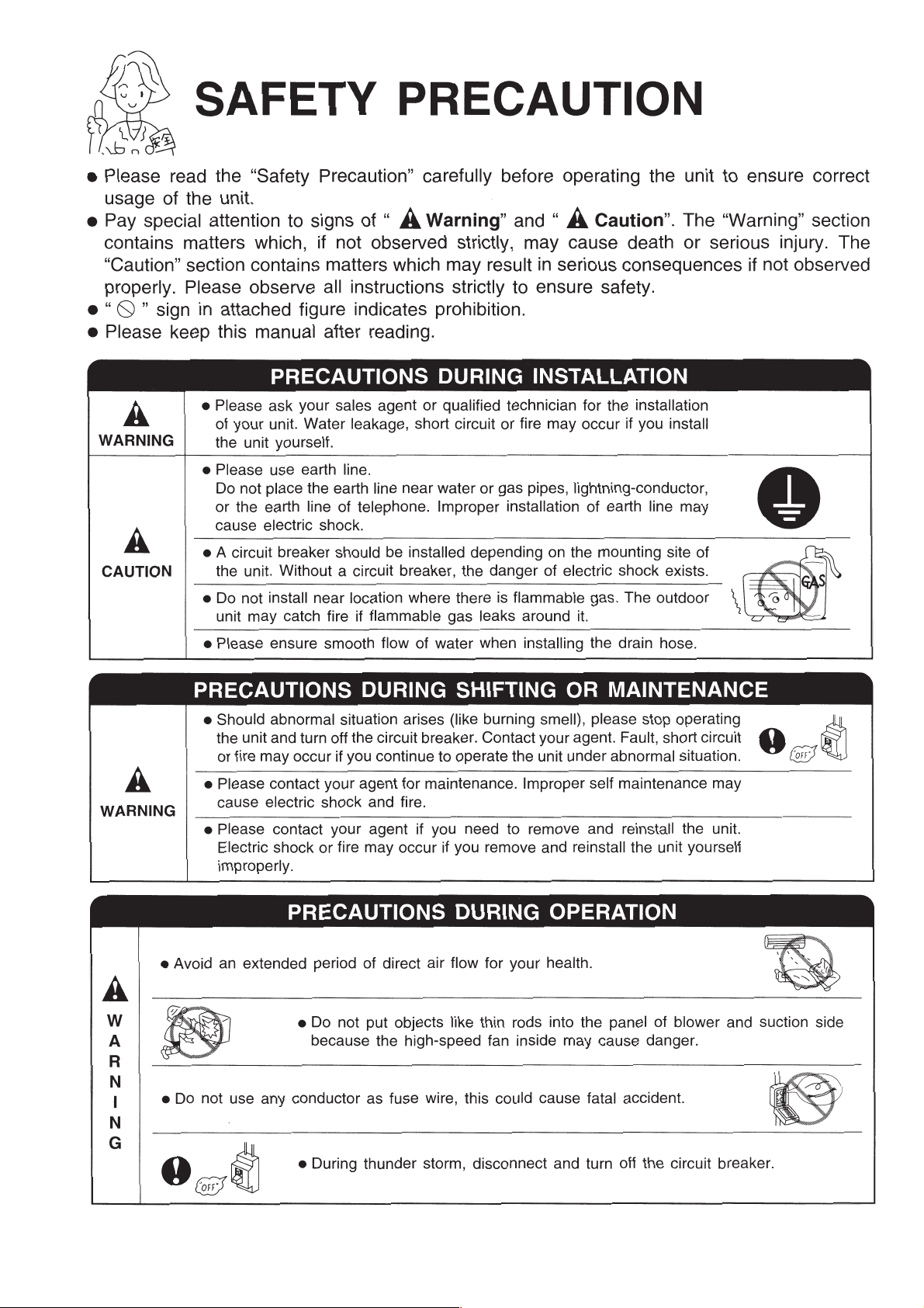
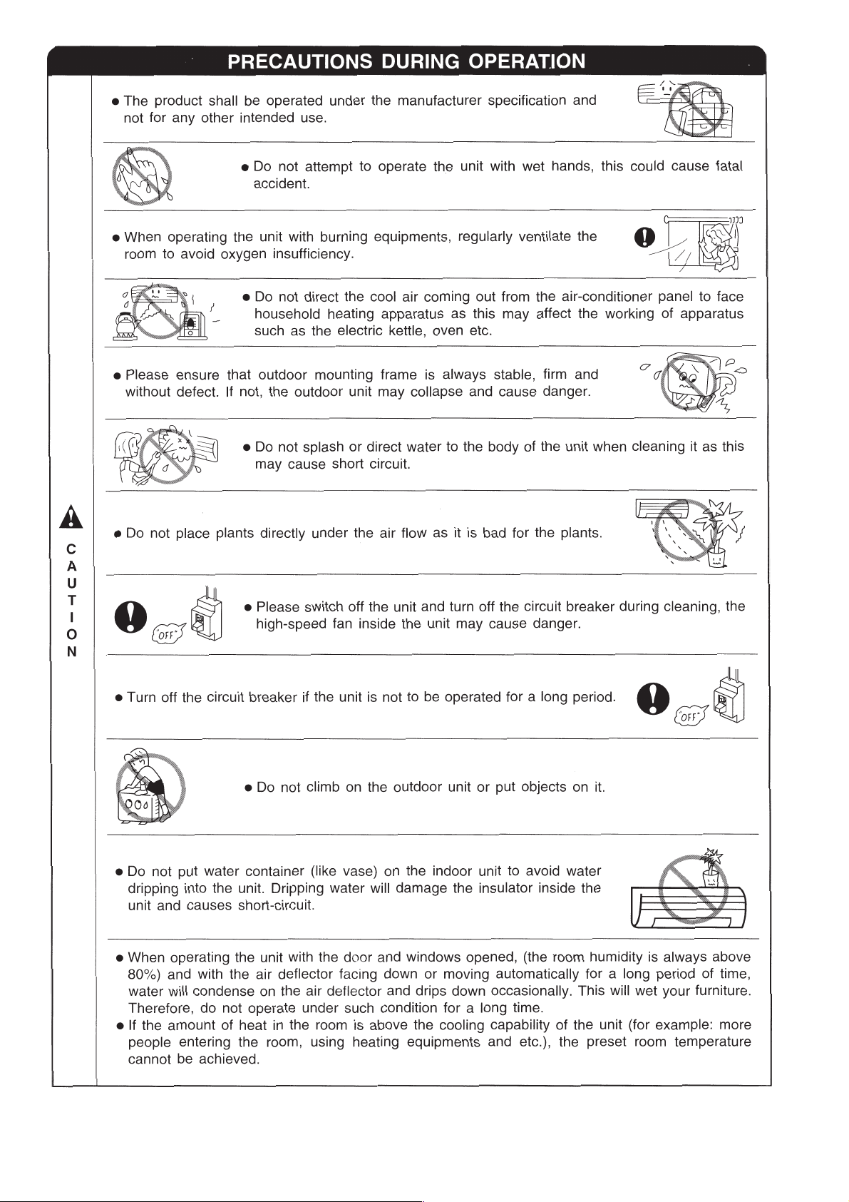
SAFETY PRECAUTION ----------------------------------------------------------- 5
HOW TO USE ------------------------------------------------------------------------ 7
CONSTRUCTION AND DIMENSIONAL DIAGRAM ---------------------- 25
MAIN PARTS COMPONENT --------------------------------------------------- 26
WIRING DIAGRAM ----------------------------------------------------------------- 28
BASIC MODE ------------------------------------------------------------------------ 35
AUTO SWING FUNCTION ------------------------------------------------------- 39
REFRIGERATING CYCLE DIAGRAM ---------------------------------------- 28
SERVICE CALL Q & A ----------------------------------------------------------- 28
TROUBLE-SHOOTING ------------------------------------------------------------40
PARTS LIST AND DIAGRAM --------------------------------------------------- 42
SPECIFICATIONS
TYPE
MODEL
POWER SOURCE
TOTAL INPUT
COOLING
HEATING
DIMENSIONS (mm)
NET WEIGHT (kg)
TOTAL AMPERES
CAPACITY
TOTAL INPUT
TOTAL AMPERES
CAPACITY
(W)
(A)
(kW)
(B.T.U./h)
(W)
(A)
(kW)
(B.T.U./h)
W
H
D
WALL TYPE
INDOOR UNIT OUTDOOR UNIT
RAS-14CH3, RAS-14CH1 RAC-14CH3, RAC-14CH1
1Ø, 220 – 230 V, 50 Hz
1290 – 1330
6.0 – 5.9
3.55 – 3.60
12110 – 12284
1370 – 1410
6.3 – 6.2
4.10 – 4.15
13990 – 14160
815 820
298 520
179❈(185) 280
839
❈ After installation
SPECIFICATIONS AND PARTS ARE SUBJECT TO CHANGE FOR IMPROVEMENT
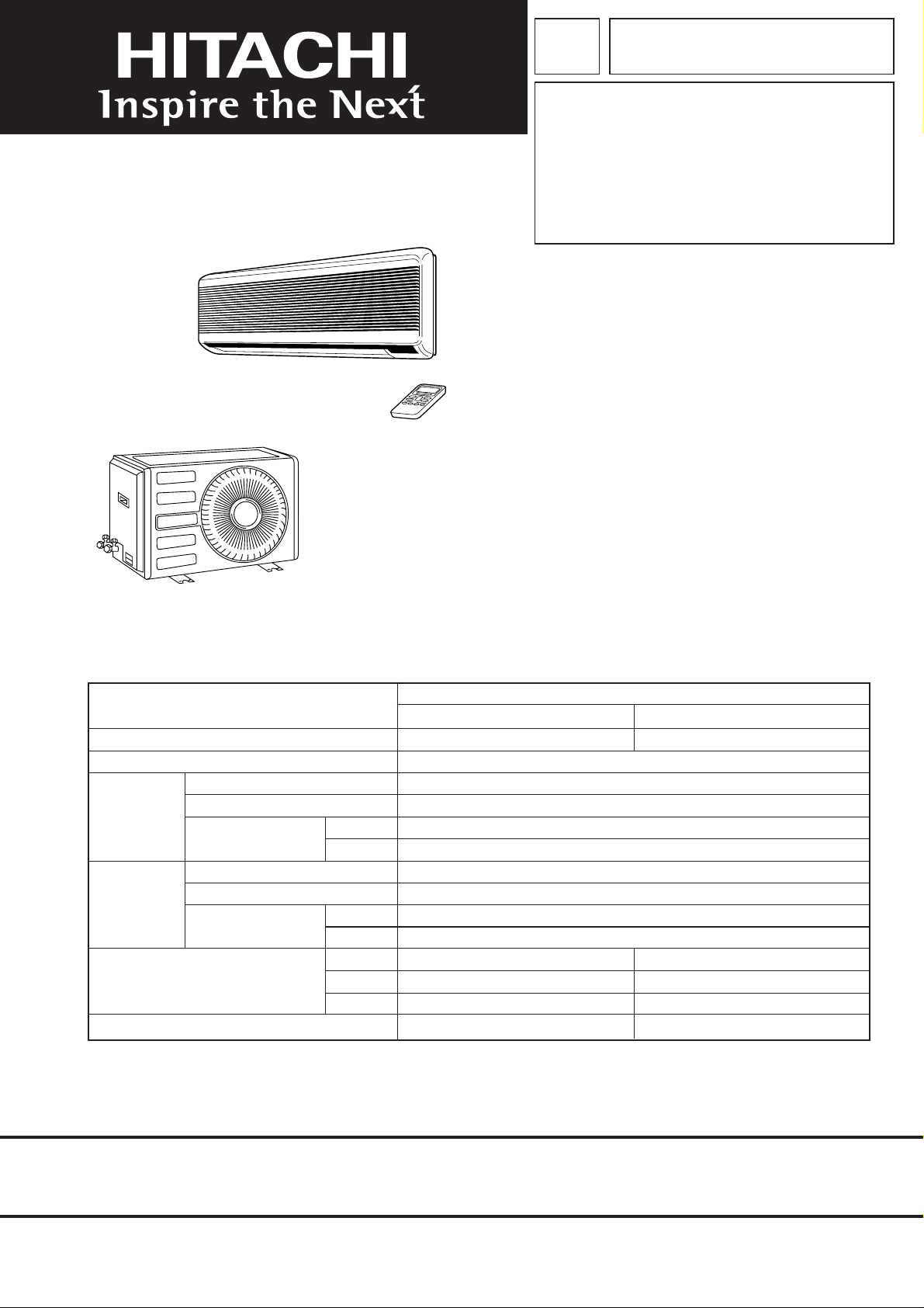
ROOM AIR CONDITIONER
INDOOR UNIT + OUTDOOR UNIT
JANUARY 2003
H.A.P.M.
Page 2
SAFETY DURING REPAIR WORK
First, I must disconnect
the power cord plug
from the power outlet.
DANGER
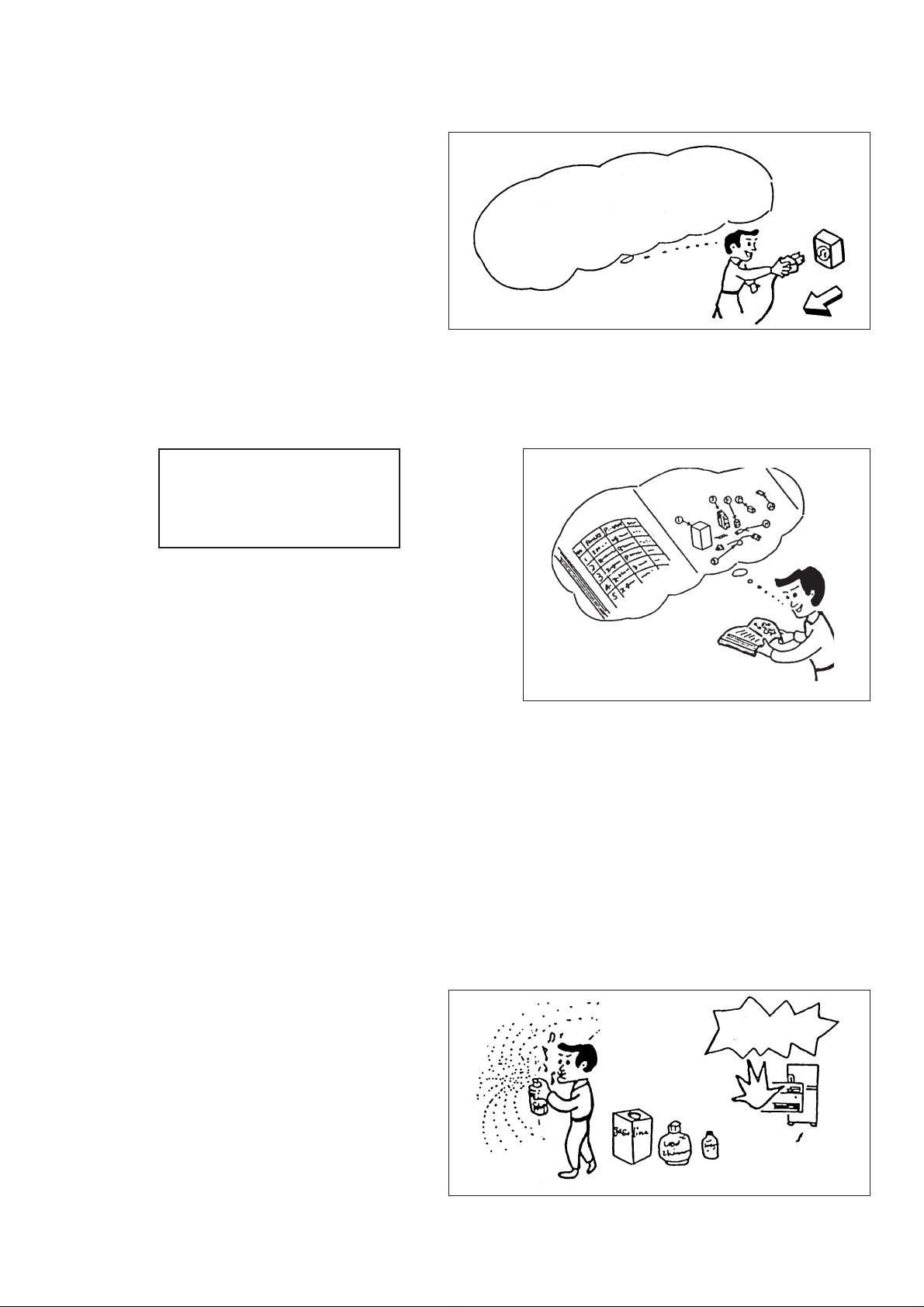
1. In order to disassemble and repair the unit
in question, be sure to disconnect the power
cord plug from the power outlet before
starting the work.
2. If it is necessary to replace any parts, they should be replaced with respective genuine parts for the unit,
and the replacement must be effected in correct manner according to the instructions in the Service Manual
of the unit.
If the contacts of electrical
parts are defective, replace
the electrical parts without
trying to repair them.
3. After completion of repairs, the initial state should
be restored.
4. Lead wires should be connected and laid as in
the initial state.
5. Modification of the unit by the user himself should
absolutely be prohibited.
6. Tools and measuring instruments for use in repairs or inspection should be accurately calibrater in advance.
7. In installing the unit having been repaired, be careful to prevent the occurrence of any accident such as
electrical shock, leak of current, or bodily injury due to the drop of any part.
8. To check the insulation of the unit, measure the insulation resistance between the power cord plug and
grounding terminal of the unit.
The insulation resistance should be 1 MΩ or more as measured by a 500V DC megger.
9. The initial location of installation such as window, floor or the other should be checked for being safe enough
to support the repaired unit again.
If it is found not so strong and safe, the unit should be installed at the initial location after reinforced or at
a new location.
10. Any inflammable thing should never be
placed about the location of installation.
11. Check the grounding to see whether it
is proper or not, and if it is found
improper, connect the grounding
terminal to the earth.
– 1 –
Page 3
PREVENTION OF DAMAGE TO SEMICONDUCTORS
1. When carrying and handling semiconductors adopted in your Model during maintenanace and inspection
thereof, much care should be taken to prevent the semiconductors from being damaged. Also, such care
should be taken when handling any faulty Model which is to be returned to factory.
2. The semiconductors used in your Model are the following :
(1) Micro computer
(2) Integrated circuits (IC)
(3) Field-effect transistors (FET)
(4) Printed circuit boards (PC boards) or the like on which the parts in (1) and (2) above are provided
3. Cautions in handling
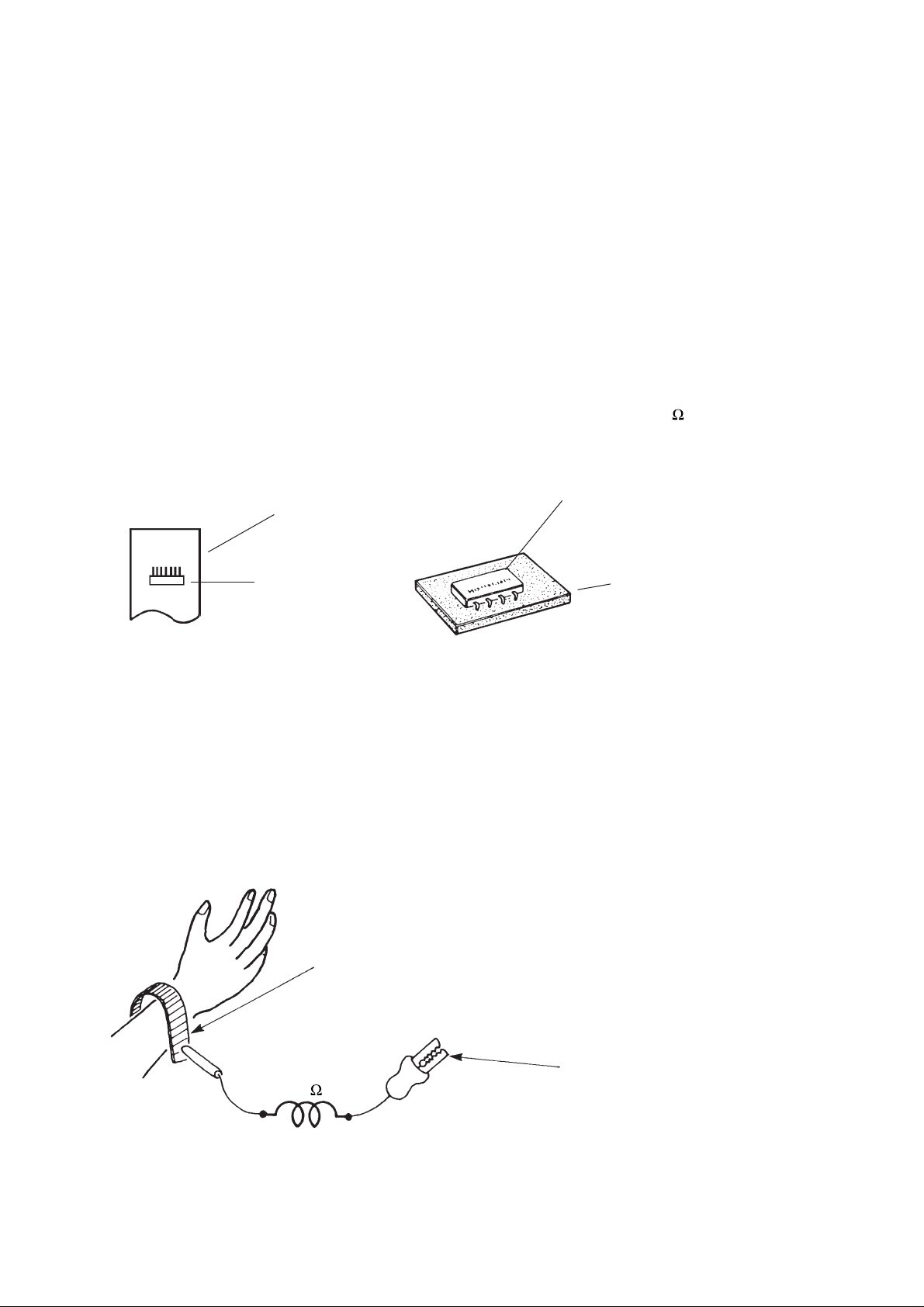
(1) Use a conductive container to carry or store the semiconductive parts. Even if they are faulty ones, also
handle them using such container.
(2) When parts as uncovered are handled (for counting, packing or for the like purpose), the hadler must use
his own body as conductor for earthing. For this purpose, put on an electrically conductive ring or bracelet
at the wrist. Connect to the bracelet a conductor provided with a resistor of 1 M
and at the other end
with a clip for connection to the earth wire.
Conductive polyvinyl bag
▲
▲
IC
▲
IC
Conductive sponge
▲
Fig. 1 Conductive Container
(3) Be careful not to have your clothes be in contact with any part while you are holding it, even if the body
earthing is established.
(4) Be sure to place the parts on a grounded metallic plate.
(5) Never fail to disconnect the power supply before starting repair of any PC board. Then, proceed to the repair
of the PC board on the grounded metallic plate.
Bracelet for body earthing
(Elimik conductive band)
1M
Fig. 2 Body Earthing
Clip for connection to each wire
– 2 –
Page 4
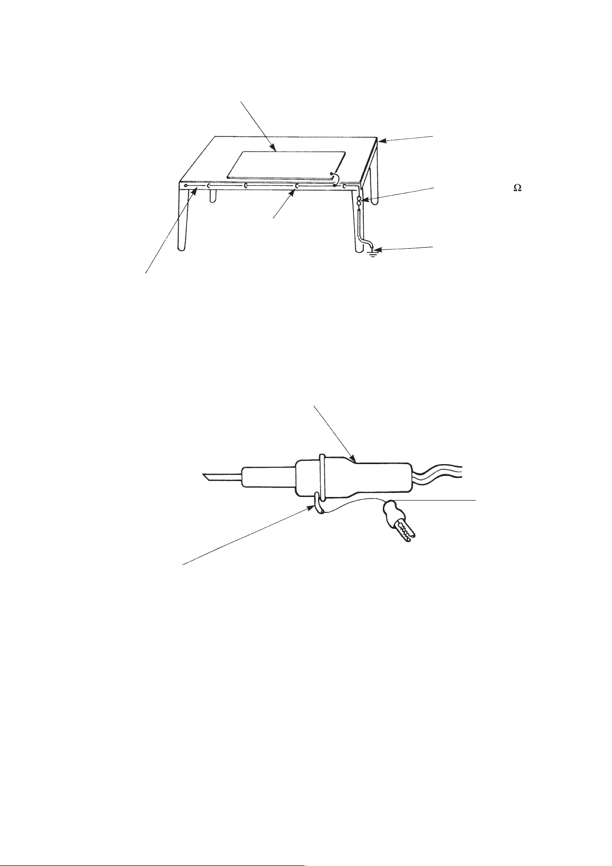
(6) Soldering iron to be used should be a one with three wires (including an earth wire).
Metallic plate (of aluminium, stainless steel or other)
or conductive rubber sheet
Work table
Bare copper wire (for body earthing)
Staple the wire
Fig. 3. Earthing of Work Table
Soldering iron
Resistor of 1 M
Earth wire
(1/2W)
2
Screw here using a rag plate
Fig. 4. Earthing of Soldering Iron
An ordinary soldering iron may also be used, but in such case, be sure to provide a perfect insulation (10MΩ
or more to 100volts).
(7) While checking the circuits during maintenance, inspection or the other, strictly avoid any shortcircuiting of the
load circuit or other by the test probe of the measuring instrument.
Earth wire
– 3 –
Page 5

SPECIFICATIONS
MODEL
FAN MOTOR
FAN MOTOR CAPACITOR
FAN MOTOR PROTECTOR
COMPRESSOR
COMPRESSOR MOTOR CAPACITOR
OVERLOAD PROTECTOR
PROTECTOR
FUSE (for MICRO COMPUTER)
POWER RELAY
POWER SWITCH
RAS-14CH3
10 W
1 µF, 450V
YES (INTERNAL)
NO
NO
NO
NO
3.0A
G4A-RY-200
YES
RAS-14CH1
10 W
1 µF, 450V
YES (INTERNAL)
NO
NO
NO
NO
3.0A
G4A-RY-200
YES
RAC-14CH3
20 W
2.5 µF, 450V
YES (INTERNAL)
SH933RC2-U
35 µF, 440V
NO
YES
NO
NO
NO
RAS-14CH1
20 W
2.5 µF, 450V
YES (INTERNAL)
SH933RC2-U
35 µF, 440V
NO
YES
NO
NO
NO
TEMPORARY SWITCH
SERVICE SWITCH
TRANSFORMER
VARISTOR
NOISE SUPPRESSOR
SOLID STATE RELAY FOR FAN (FAN SSR)
EXTERNAL FAN AND REVERSING VALVE RELAY
REMOTE CONTROL SWITCH (LIQUID CRYSTAL)
THERMOSTAT
FUSE CAPACITY
UNIT
450NR
S26MD02
YES (IC)
––––– ❈ 1,080g
YES
YES
YES
NO
G4U
YES
YES
YES
YES
450NR
NO
S26MD02
G4U
YES
YES (IC)
15 A TIME DELAY FUSE
NO
NO
NO
NO
NO
NO
NO
NO
NO
NO
NO
NO
NO
NO
NO
NO
NO
NO
❈ 1,080g–––––
REFRIGERANT
CHARGING VOLUME
(Refrigerant 22)
❈ 1080g for piping set of 5 ~ 8m, additional 25g/m R22 is required for additional 8m onward, but cannot exceed
10m.
PIPES
WITHOUT REFRIGERANT BECAUSE
COUPLING IS FLARE TYPE.
P-103VK1 (3m), P-105VK1 (5m),
P-108VK1 (8m), (P-103VK), (P-105VK)
– 4 –
Page 6
– 5 –
Page 7
– 6 –
Page 8
– 7 –
Page 9
– 8 –
Page 10
– 9 –
Page 11
– 10 –
Page 12
– 11 –
Page 13
– 12 –
Page 14
– 13 –
Page 15

– 14 –
Page 16

– 15 –
Page 17

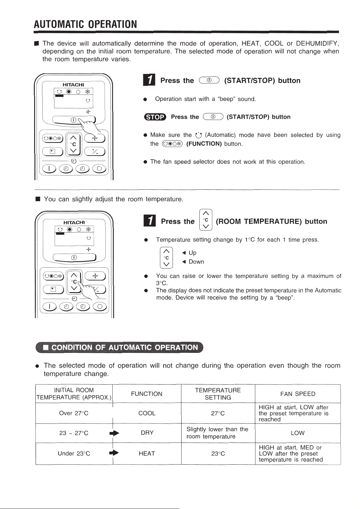
THE IDEAL W AYS OF OPERA TION
Suitable Room Temperature Install curtain or blinds
Warning
Freezing temperature
is bad for health and a
waste of electric power.
Ventilation Effective Usage Of Timer
Caution
Do not close the room for a long period of
time. Occasionally open the door and windows
to allow the
entrance of
fresh air.
It is possible to
reduce heat
entering the
room through
windows.
At night, please use the “sleep timer operation
mode”, together with your wake up time in the
morning. This will enable you to enjoy a
comfortable room temperature. Please use the
timer effectively.
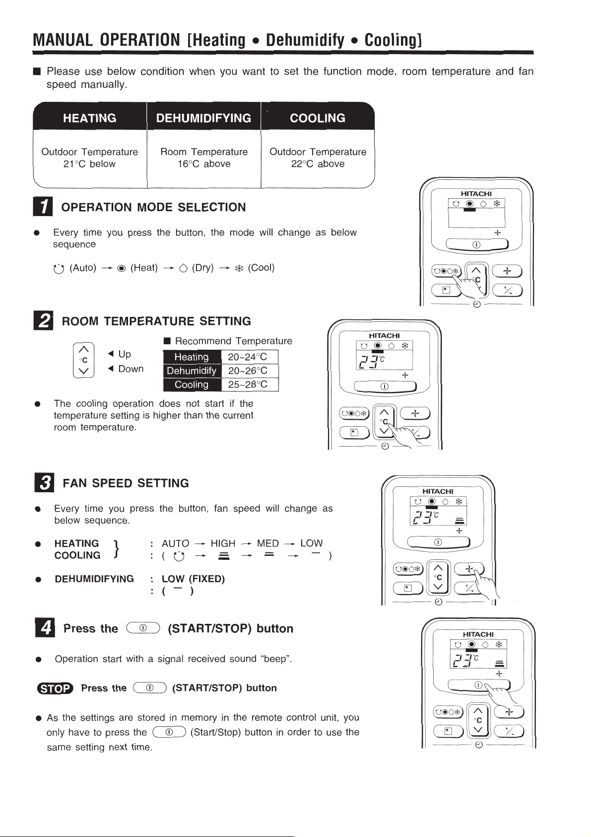
Do Not Forget To Clean The Air Filter
Dusty air filter will reduce the air volume and
the cooling efficiency. To prevent from wasting
electric energy, please clean the filter every 2
weeks.
Please Adjust Suitable Temperature
For Baby And Children
Please pay attention to the room temperature
and air flow direction when operating the unit
for baby, children and old folks who have
difficulty in movement.
(The ideal temperature
difference between
outdoor and indoor
is about ±5˚C).
– 16 –
Page 18

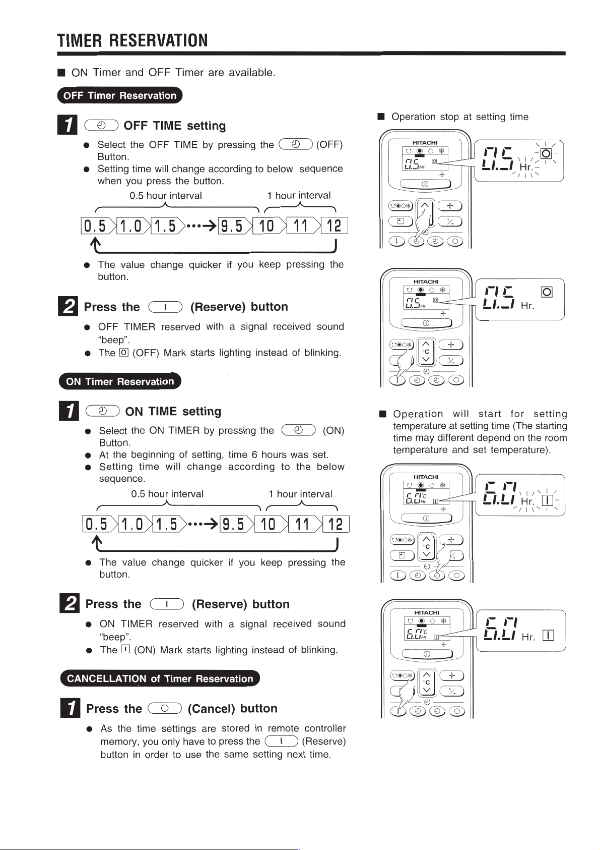
FOR USER’S INFORMA TION
OFF
The Air Conditioner And The Heat Source In The Room
Caution
If the amount of heat in the room is above the cooling
capability of the air conditioner (for example: more
people entering the room, using heating equipments
and etc.), the preset room temperature cannot be
achieved.
After Power Failure
When the power is resumed after a power failure,
the indoor unit will still remain “OFF”. To operate the
unit, please press the “ON/OFF” button again.
After power
failure
Not Operating For A Long Time
When the indoor unit is not to be used for a long
period of time, please switch off the power from the
mains. If the power from mains remains “ON”, the
indoor unit still consumes about 15W in the operation
control circuit even if it is in “OFF” mode.
When Lightning Occurs
Warning
To protect the whole unit during lightning, please
stop operating the unit and remove the plug from the
socket.
Operate
– 17 –
Page 19

– 18 –
Page 20

– 19 –
Page 21

– 20 –
Page 22

280(11-1/32")
260(10-1/4")
145(5-11/16")
12(1/2")
50(2")
500(19-11/16")
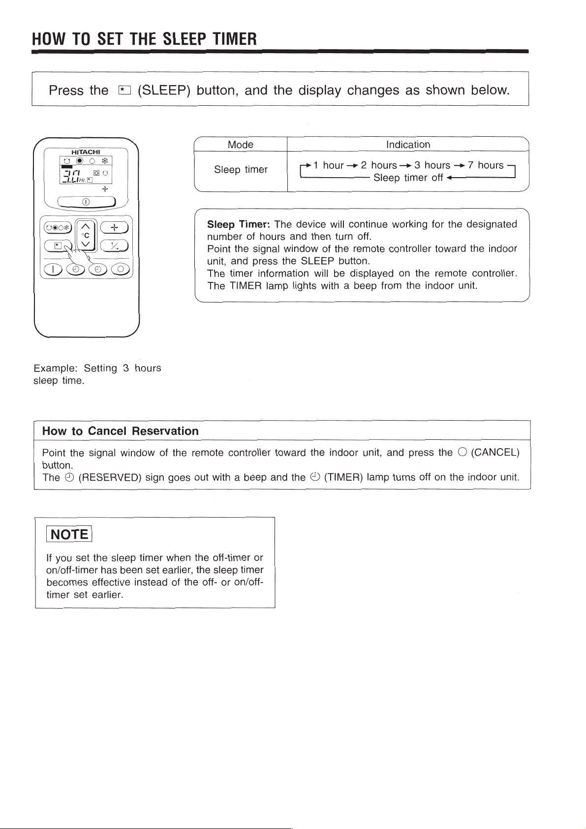
CONSTRUCTION AND DIMENSIONAL DIAGRAM
15
MODEL RAS-14CH3
RAS-14CH1
Air suction grill
6(1/4")
Mounting plate
56
(2-3/16")
Viewed from P
(bottom direction pipe lead-out)
About 290
(11-3/8")
About 360
179(7-1/16")
Discharge grill
About 400
(15-3/4")
VIEWED FROM BACK
(PIPE LEAD-OUT)
(14-3/16")
40(1-9/16")
64(2-1/2")
103(4-1/16")
110
(4-5/16")
42.5(1-11/16")
785(30-7/8")
Vertical air deflector
182.5
(7-3/16")
Hole on the wall for
ø65mm(2-9/16") pipe
450(17-11/16")
58(2-5/16") 58(2-5/16")
Drain outlet
Drain hose
Connecting cable
Line cord
815(32-1/16")
Wide pipe (ø12.70(1/2"))
62
Wireless remote controller
Top Air suction grill
Front cover
179(7-1/16")
298(11-3/4")
Horizontal air
deflector
Drain pan
182.5
(7-3/16")
P
Drain cap
connection port
7(1/4")
❈When piping is drawn horizontally,
exchange the drain hose for the drain cap.
Narrow pipe (ø6.35(1/4"))
120
Cabinet
47(1-7/8")
mm(inch)
MODEL RAC-14CH3
RAC-14CH1
820(32-5/16")
500(19-11/16")
12(1/2")
50(2")
520(20-1/2")
500(19-11/16")
270(10-21/32")
145(5-11/16")
280(11-1/32")
260(10-1/4")
– 21 –
Page 23

MAIN PARTS COMPONENT
THERMOSTAT
Thermostat Specifications
MODEL
RAS-14CH3, RAS-14CH1
THERMOSTAT MODEL
OPERATION MODE
INDICATION
16
ON
OFF
COOL
17.6 (63.7)
17.3 (63.1)
TEMPERATURE
°C (°F)
INDICATION
24
INDICATION
32
ON
OFF
ON
OFF
25.6 (78.1)
25.3 (77.5)
33.6 (92.5)
33.3 (91.9)
FAN MOTOR
Fan Motor Specifications
MODEL
RAS-14CH3, RAS-14CH1 RAC-14CH3, RAC-14CH1
PHASE SINGLE
IC
HEAT
19.6 (67.3)
19.3 (66.7)
27.6 (81.7)
27.3 (81.1)
35.6 (96.1)
35.3 (95.5)
RATED VOLTAGE 220 – 240 V
RATED FREQUENCY 50 Hz
OUTPUT 10 W 20 W
POLE NUMBER 4 6
INTERNAL
THERMAL FUSE
BLACK
CAPACITOR
RA = 162.37
RM = 328.36
RA = 197.46
RM = 399.32
RM
CONNECTION
RESISTANCE VALUE
(
1
A1
3
A2
2
A3
654
20°C
(68°F)
)
75°C
(167°F)
RM = 444.00 RA2 = 53.10
RA1 = 113.90 RA3 =125.30
RM = 539.95 RA2 = 64.58
RA1 = 138.50 RA3 =152.38
M
T. F
Cr
RED
RA
GRAY
– 22 –
Page 24

COMPRESSOR
POWER
SOURCE
RUNNING
CAPACITOR
RM
RA
INTERNAL
PROTECTOR
Compressor Motor Specifications
MODEL RAC-14CH3, RAC-14CH1
COMPRESSOR MODEL SH933RC2-U
PHASE SINGLE
RATED VOLTAGE 220 – 240 V
RATED FREQUENCY 50 Hz
LOCKED ROTOR CURRENT 27 A
POLE NUMBER 2
RUNNING
CONNECTION
CAPACITOR
POWER
SOURCE
S
RA
R
RM
C
INTERNAL
PROTECTOR
RESISTANCE VALUE
(
20°C
(68°F)
)
75°C
(167°F)
RM = 2.87
RA = 2.15
RM = 3.49
RA = 2.61
M/R (ORANGE)
S (RED)
C (WHITE)
CAUTION
When the Air Conditioner has been operated for a long time with the capiliary tubes clogged or crushed
or with too little coolant, check the color of the refrigerant oil inside the compressor. If the color has been
changed conspicuously, replace the compressor.
– 23 –
Page 25

WIRING DIAGRAM
MODEL RAS-14CH3, RAS-14CH1
RAC-14CH3, RAC-14CH1
A : COMPRESSOR
B : FAN MOTOR
C : POWER SWITCH
D : 1,000 pF CAPACITOR
E : INDOOR FAN MOTOR
PROTECTOR (INTERNAL)
F:1 µF CAPACITOR
G : 35 µF CAPACITOR
H : 2.5 µF CAPACITOR
I : FAN MOTOR PROTECTOR
J : TERMINAL BOARD
K : LINE CORD
L : EXTERNAL FAN RELAY
M : STICK RELAY
N : REVERSING VALVE
P : POWER RELAY
Q : THERMAL FUSE
R : SURGE ABSORBER
S : THERMISTOR
T : TRANSFORMER
U : INTERNAL PROTECTOR
V : VARISTOR
W : SOLID STATE RELAY FOR FAN (FAN SSR)
X : FUSE
Y : REVERSING VALVE RELAY
Z : AUTO SWEEP MOTOR
BLU : BLUE YEL : YELLOW BRN : BROWN WHT : WHITE
GRY : GRAY ORN : ORANGE GRN : GREEN RED : RED
BLK : BLACK PNK : PINK VIO : VIOLET
INDOOR UNIT OUTDOOR UNIT
C
(3.0A)
X
(96°C)
V
2
PRINTED WIRING
BOARD ASSEMBLY
V
Q
1
(109°C)
X
R
I
T
D
P
H M L
B
W
Y
F
J
B B
L
I
(165°C)
B
N
U
H
A
G
M
A A
C C
D D
E
– 24 –
Page 26

BRNBRN
BLUBLU
BLUBLU
(RED) S(RED) S
ORNORN
M/RM/R
(ORN)(ORN)
(WHT) C(WHT) C
REDRED
GRYGRY
GRYGRY
BLK
BLKBLK
BLKBLK
BLK
WHTWHT
REDRED
BLK
A
B
A
B
N
H
G
B
A
J
BLK
WHTWHT
BLU
PNKPNK
YELYEL
ORNORN
REDRED
CN13CN13
REDRED
REDRED
S
8
CN11CN11
CN12CN12
BLK
BLKBLK
S
B
E
BLKBLK
F
CN3CN3
W
L
M
H
R
K
2
CN1CN1
(96°C)C)
Q
T
ORNORN
ORNORN
GRYGRY
GRYGRY
CN2CN2
BRNBRN
V
V
BLK
X
P
M
34
34
(3.0A)(3.0A)
C
2 BRN2 BRN
4 BLU
1
3
BRNBRN
BLU
YELYEL
+GRN +GRN
YEL
GRYGRY
BLU
WHTWHT
REDRED
BLK
YELYEL
GRYGRY
BLU
WHTWHT
RED
1
BRNBRN
YEL+GRNYEL+GRN
INDOOR UNIT OUTDOOR UNITINDOOR UNIT OUTDOOR UNIT
Z
Y
L
C
D
BRWBRW
REDRED
CN4CN4
C
D
M
– 25 –
Page 27

– 27 –
Page 28

– 29 –
Page 29

– 31 –
Page 30

– 33 –
Page 31

– 34 –
Page 32

– 35 –
Page 33

– 36 –
Page 34

– 37 –
Page 35

– 38 –
Page 36

– 39 –
Page 37

– 40 –
Page 38

– 41 –
Page 39

– 42 –
Page 40

PARTS LIST AND DIAGRAM
MODEL RAS-14CH3, RAS-14CH1
27
100
26
44
23
104
42
109
101
12
13
102
49
61
60
24
48
89
11
10
7
1
62
190
63
86
– 43 –
Page 41

MODEL RAS-14CH3, RAS-14CH1
NO. Q’TY/UNIT PARTS NAME
1 PMRAS-12CH1 002 1 EVAPORATOR
7 PMRAS-12CH1 001 1 FAN MOTOR 10W
10 PMRAS-09C1 003 1 TANGENTIAL FLOW FAN
11 PMRAS-05C 013 1 P-BEARING ASSEMBLY
12 PMRAS-14CH1 001 1 CAPACITOR 1µF, 450V
13 PMRAS-07C1 006 2 TERMINAL BOARD (2P)
23 PMRAS-12CH1 003 1 CABINET
24 PMRAS-12CH1 004 1 DRAIN PAN ASSEMBLY
26 PMRAS-12CH1 005 1 FRONT COVER ASSEMBLY
27 PMRAS-252B 012 2 FILTER
42 PMRA-13CDF 905 1 THERMAL FUSE
44 PMRAS-14CH1 004 1 MOUNTING PLATE
48 RAS-288CX 004 1 FAN COVER
RAS-14CH3, RAS-14CH1
PART N0.
49 PMRAS-07C1 013 1 DRAIN HOSE
62 PMRAS-14CH1 003 1 FAN MOTOR SUPPORT (L)
63 PMRAS-14CH1 005 1 FAN MOTOR SUPPORT (R)
86 PMRAS-25CNH2 017 1 REMOTE CONTROL HOLDER
89 PMRAS-12CH1 006 1 AUTO SWEEP MOTOR
100 PMRAS-25CNH2 013 1 REMOTE CONTROL
101 PMRAS-12CH1 007 1 P.W.B. (MAIN)
102 PMRAS-5142CHA 002 1 P.W.B. INDICATE
104 PMRAS-5142CH 004 1 TRANSFORMER
109 PMRAS-18CP2R 002 1 SWITCH
112 PMRAS-14CH1 006 1 THERMISTOR (ROOM TEMP.)
115 PMRAS-14CH1 002 1 FUSE (3.0A)
190 PMRAS-5101C 915 1 THERMISTOR (HEAT EXCHANGER)
– 44 –
Page 42

MODEL RAC-14CH3, RAC-14CH1
2
54
4
17
40
1
38
39
55
46
47
21
26
25
41
44
24
– 45 –
Page 43

MODEL RAC-14CH3, RAC-14CH1
NO. Q’TY/UNIT PARTS NAME
1 PMRAC-5142CHV 902 1 COMPRESSOR
2 PMRAC-12CH1 901 1 CONDENSER
4 PMRAC-12CH1 902 1 REVERSING VALVE
17 PMRAC-12CH1 903 1 MG-COIL (REVERSING VALVE)
21 PMRAC-5142CV 905 1 FAN MOTOR 20W/3KG
24 PMRAC-13CV6 904 1 PROPELLER FAN
25 PMRAC-14CH1 902 1 CAPACITOR 35µF, 440V
26 PMRAC-14CH1 901 1 CAPACITOR 2.5µF, 450V
38 PMRAC-12CH1 904 1 CABINET
39 PMRAC-5142CV 907 1 SIDE PLATE (L)
40 PMRAC-5142CV 908 1 SIDE PLATE (R)
41 PMRAC-5142CV 909 1 BACK PLATE
44 PMRAS-07C1 006 2 TERMINAL BOARD (2P)
RAC-14CH3, RAC-14CH1
PART N0.
46 PMRAC-5142CV 910 1 VALVE (2S)
47 PMRAC-5142CV 911 1 VALVE (4S)
54 PMRAC-5142CV 913 1 STRAINER
55 PMRAC-5142CHV1 902 3 COMPRESSOR RUBBER
– 46 –
Page 44

RAS-14CH3, RAS-14CH1 PM NO. 0159E
RAC-14CH3, RAC-14CH1
– 47 –
Printed in Malaysia
 Loading...