

Hisense WFU7012, WFU7012S, WFUA7012, WFUA7012S Service Manual

WASHING MACHINE
SERVICE MANUAL
WFU7012&WFU7012S
WFUA7012&WFUA7012S
CAUTION
READ THIS MANUAL CAREFULLY TO DIAGNOSE
PROBLEMS CORRECTLY BEFORE SERVICING THE UNIT.

CONTENTS
1
CONTENTS
1. SAFETY NOTICES………………………………………………….…….…1
2. SPECIFICATIONS…………………………………………………………...3
3. FEATURES & TECHNICAL EXPLANATION…………………..………….4
3.1 FEATURES .......................................................................................... 3
3.2 INTELLIGENT FUZZY CONTROL ...................................................... 4
3.3 POWER SUPPLY CONTROL .............................................................. 4
3.4 WATER LEVEL CONTROL ................................................................. 5
3.5 DOOR LOCK CONTROL .................................................................... 5
3.6 LAUNDERING CONTROL .................................................................. 6
3.7 HEATING CONTROL .......................................................................... 7
3.8 SPINNING CONTROL ......................................................................... 7
4. PARTS IDENTIFICATION.....................................................................10
5. INSTALLATION AND TEST...................................................................11
5.1 STANDARD INSTALLATION ............................................................. 10
5.2 CONNECT THE INLET HOSE .......................................................... 11
5.3 CONNECT THE DRAIN HOSE ......................................................... 11
5.4 CONNECT POWER PLUG ............................................................... 11
5.5 TEST OPERATION ............................................................................ 11
6. OPERATION.........................................................................................14
6.1 CONTROL PANEL ............................................................................. 13
6.2 CYCLE GUIDE .................................................................................. 14
6.3 COMMON FUNCTIONS .................................................................... 16
6.4 ADDITIONAL FUNCTIONS ............................................................... 18
7. WIRING DIAGRAM/PROGRAM CHART...............................................22
7.1 WIRING DIAGRAM ........................................................................... 21

CONTENTS
2
7.2 PROGRAM CHART ........................................................................... 23
8. TEST MODE.........................................................................................25
8.1 SELF-INSPECTION MODE ............................................................... 24
8.2 SPECIAL FUNCTION MODE ............................................................ 26
9. TROUBLESHOOTING..........................................................................29
9.1 SAFETY CAUTION ........................................................................... 28
9.2 ERROR MODE SUMMERY .............................................................. 28
9.3 TROUBLESHOOTING WITH ERROR .............................................. 30
9.4 TROUBLE SHOOTING ELSE ........................................................... 36
10. COMPONENT TESTING INFORMATION..........................................40
10.1 FILTER ............................................................................................ 39
10.2 DOOR LOCK ................................................................................... 40
10.3 MOTOR ........................................................................................... 41
10.4 PUMP .............................................................................................. 42
10.5 INLET VALVE .................................................................................. 43
10.6 HEATER .......................................................................................... 44
11. DISASSEMBLY INSTRUCTIONS.......................................................46
11.1 CONTROL PANEL ASM .................................................................. 45
11.2 DISPENSER ASM ........................................................................... 46
11.3 FILTER ............................................................................................. 47
11.4 DOOR ASM ..................................................................................... 48
11.5 FRONT PANEL ................................................................................ 49
11.6 PUMP .............................................................................................. 50
11.7 HEATER .......................................................................................... 50
11.8 MOTOR ........................................................................................... 51
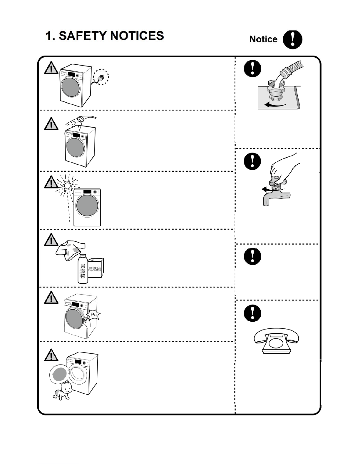
1. SAFETY NOTICES
1
• Cut off the power first before maintaining and
repairing the washing machine.
• It is for preventing from harms duet to electric
leakage.
• Please do not sprinkle or spray water directly
to any part of the washing machine during
maintenance and repair.
• Otherwise, accidents like short circuit or
electric shock may happen.
• Please do not place the washing machine in
places where are damp or are exposed to wind,
rain and the sun.
• It is for preventing from fire accidents due to
electric shock or electric leakage.
Explosion Or Fire
• It is strictly prohibited to place the clothes
smeared with inflammables into the drum of
washing machine.
• It is for preventing from possible explosion or
fire accident.
Mechanical Injury
• Do not open the door in a forced way.
• It is for preventing from possible damage.
Safety Tips For Children
• Please do not let the children to use the
washing machine, and do not place rack,
stools, etc. around the washing machine.
• The children may suffer personal injury due
to they climbing the washing machine or
crawling into the drum.
The nut connecting water
inlet tube to the machine
must be screwed u
p
.
When the washing machine
is unused, please be sure to
turn off the faucet.
Please dismantle the door of
machine before discarding
and handlin
g
.
If the washing machine is
damaged during transportation,
please do not use it. Please
call the “After-sales Service
Personnel”.
2. SPECIFICATION
2
ITEM WFU7012& WFUA7012/ WFU7012S& WFUA7012S
COLOR WHITE/SILVER
POWER SUPPLY
AC 220-240 V,50 Hz
PRODUCT WEIGHT 72 Kg
ELECTRIC POWER
CONSUMTION
WASHING 300 W
HEATER 1900 W
REVOLUTION
SPEED
WASH 55 rpm
SPIN 1200 rpm
CYCLES 15
WASH/RINSE TEMPERATURES
20-❉/30/40/60/95℃
SPIN SPEEDS 0/600/800/1000/1200 rpm
OPTIONS
Delay、Eco wash、Prewash、Rinse hold、Extra rinse
、
Intensive wash、Mute Function、Child lock
WATER CIRCULATION 0.1-1 MPa
CONTROL TYPE Electronic
Washing Capacity 7 Kg
Dimension 595 X600 X 850 mm
DELAY WASH up to 24 hours
DOOR LOCK TYPE PTC
WATER LEVEL FWL Sensor control
LAUNDRY LOAD SENSING
Incorporated(Cotton、Synthetics)
ERROR DIAGNOSIS Incorporated
AUTO POWER OFF Incorporated
3. FEATURES & TECHNICAL EXPLANATION
3
3.1 FEATURES
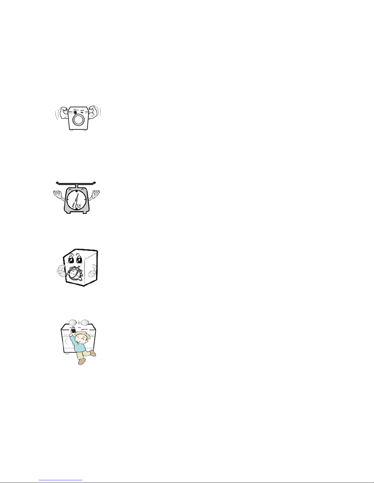
■ Ultra Capacity
The larger drum enables not just higher head drop and
stronger centrifugal force, but also less tangling and wrinkling
of the laundry. Heavier loads, such as king size comforters,
blankets, and curtains, can be washed.
■ Automatic Wash Load Detection
Automatically detects the load and optimizes the washing
time.
■ Built-in Heater
Internal heater helps to maintain water temperature at its
optimum level for selected cycles.
■ Child Lock
The Child lock prevents children from pressing any button to
change the settings during operation.
3. FEATURES & TECHNICAL EXPLANATION
4
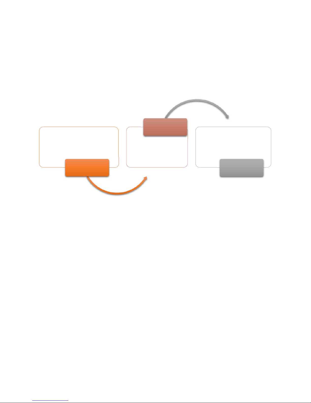
3.2 INTELLIGENT FUZZY CONTROL
In order to achieve the best washing effects, it is necessary to determine the
optimum time and washing water level based on the water supply conditions.
3.3 POWER SUPPLY CONTROL
♦ After the washing machine is energized, the PCB is under “Off mode”, and all
buttons and knobs except for the “ON/OFF” button are disabled; all loads are in
the state of ready-for-activating.
♦ After pressing the “ON/OFF” button, the PCB will switch to “Ready mode” from
“Off mode”, and conduct status inquiry for minutes, with values of parameters
like water level, water temperature, air temperature, motor speed, door lock
state, etc. obtained.
♦ When the PCB runs a complete routine to end, the “Ready mode” will display
the previous completed program, with the settings corresponding to those set
by default. If the previous flow that is not run to end, then it will restore to the
“Cotton” program by default.
• washing program
• Water supply
Sensing
• Intelligence
fuzzy
Handling
• washing time
• water level
Adjust

3. FEATURES & TECHNICAL EXPLANATION
5
♦ When the program finishes and displays “End”, the door will be unlocked, and
the PCB will enter in “End mode”.
♦ If no button-press operation is done for 3 minutes when the washing machine
is under “Ready mode”, the PCB will automatically be power off and switch to
“Off mode”. If no button-press operation is done for 30 seconds when the
washing machine is under “End mode” where the washing is completed, the
PCB will automatically be power off and switch to “Off mode”.
♦ In order to avoid the user to falsely triggering the “ON/OFF” button, two
successive seconds are required for switching from “On mode” to “Off mode”,
and only one click is required for switching from “Off mode” to “On mode”.
3.4 WATER LEVEL CONTROL
♦ This module contains a FWL sensorfor detecting the water level of tub.
♦ During water inflowing, the PCB controls the inlet valve to function and execute
the water inflow operation. When the water level reaches the “Washing water
level”, the water inflow stops and the washing process begins. If the water level
declines during washing, it will automatically activate the water inflow and
replenishing program so as to reach the “Washing water level” again.
♦ During water draining, the PCB controls the draining pump to continuously
work and begin the water draining process. When the water of tub is discharged
down to the “Spinning water level”, the Spinning process will begin.
3.5 DOOR LOCK CONTROL
♦ When the PCB enters in “Ready mode”, it will detect the state of door lock and
execute operation accordingly. When the door is unlocked, no operation is done
if the unlocking conditions are satisfied, otherwise, the door should be locked;
when the door is locked, execute unlocking operation if the unlocking conditions

3. FEATURES & TECHNICAL EXPLANATION
6
are satisfied, otherwise, the door should be maintained locked.
♦ After selecting the program and function, press the “Start/Pause” button, the
PCB controls the door lock to execute locking operation, and the “Door lock”
icon on display window is on.
♦ After the program ends, the “Door lock” icon on display window is flickering
when the unlocking conditions are satisfied, and the PCB controls the door lock
to execute unlocking operation. When the “Door lock” icon on display window is
off, the door is unlocked.
♦ The program enters in “Pause mode” from “Run mode”, and the unlocking
operation can be executed if conditions permit.
♦ In case of power outage during washing, the door will be unlocked 3 min later
(the specific time depends on the different ambient temperature).
♦ The door lock clicks when it executes the program of “lock/unlock”.
♦ Door unlocking conditions: the motor stops, the water temperature is below
50°C, and the water level is below the “Door-opening water level”.
3.6 LAUNDERING CONTROL
♦ After the PCB enters in the “Ready mode”, select proper program and function,
press down “Start/Pause” button, and the PCB controls the door lock to lock,
controls the inlet valve for water inflowing up to the “washing water level”, and
then begins the laundering process.
♦ The PCB controls the motor to execute intermittent operations in clockwise
and counterclockwise directions at a constant frequency, driving the drum to
rotate via belt sheave for purpose of laundering.
♦ Motor speed and rotation/stop ratio under “Cotton” program:

3. FEATURES & TECHNICAL EXPLANATION
7
Course Water inflow Pre-wash Wash Rinse
Motor speed 45rpm 55rpm 55rpm 55rpm
Rotation/Stop ratio 10:5 20:10 20:10 12:8
3.7 HEATING CONTROL
♦ When the temperature set by the user is higher than the water temperature,
the PCB will control the heater to function and run the heating process until the
water temperature reaches the set temperature.
♦ When the temperature set by the user is higher than the water temperature,
no heating operation is required.
♦ The heater is enabled and proceeds to function until 3 seconds pass by after
the set temperature is reached.
♦ When the water level is below the “Heating water level”, the heater should be
forced to shut down, and then replenish water.
3.8 SPINNING CONTROL
♦ During draining, the Spinning process will begin after the water of tub is
discharged down to the “Spinning water level”.
♦ The PCB controls the motor to drive the drum to rotate in clockwise direction.
Carry out distribution measurement at low speed (about 110rpm) first, and then
measure the equilibrium value. After the equilibrium value is up to standard, the
distribution measurement succeeds, and enter the stage of high-speed
Spinning.If the distribution measurement fails as the equilibrium value is too big
and does not meet the requirements, then it is necessary to continuously carry
out distribution measurement operation.
♦ Spin speed limit: The spin speed shall neither exceed the maximum speed set
by the program nor exceed the speed manually set via the “Spin” button.

3. FEATURES & TECHNICAL EXPLANATION
8
♦ During the distribution measurement, time is not reckoned in the first 10 times,
and if the distribution measurement still fails, then the time will decrease
progressively and occupy the Spinning time until the latter is run out.
♦ During Spinning, if the clothes are not spinning at last as the distribution
measurement fails all the time, then “End/Unb” will alternately display after the
program ends at an interval of 1s, the display window is on all the time, and the
alarm will give out buzzing sound.
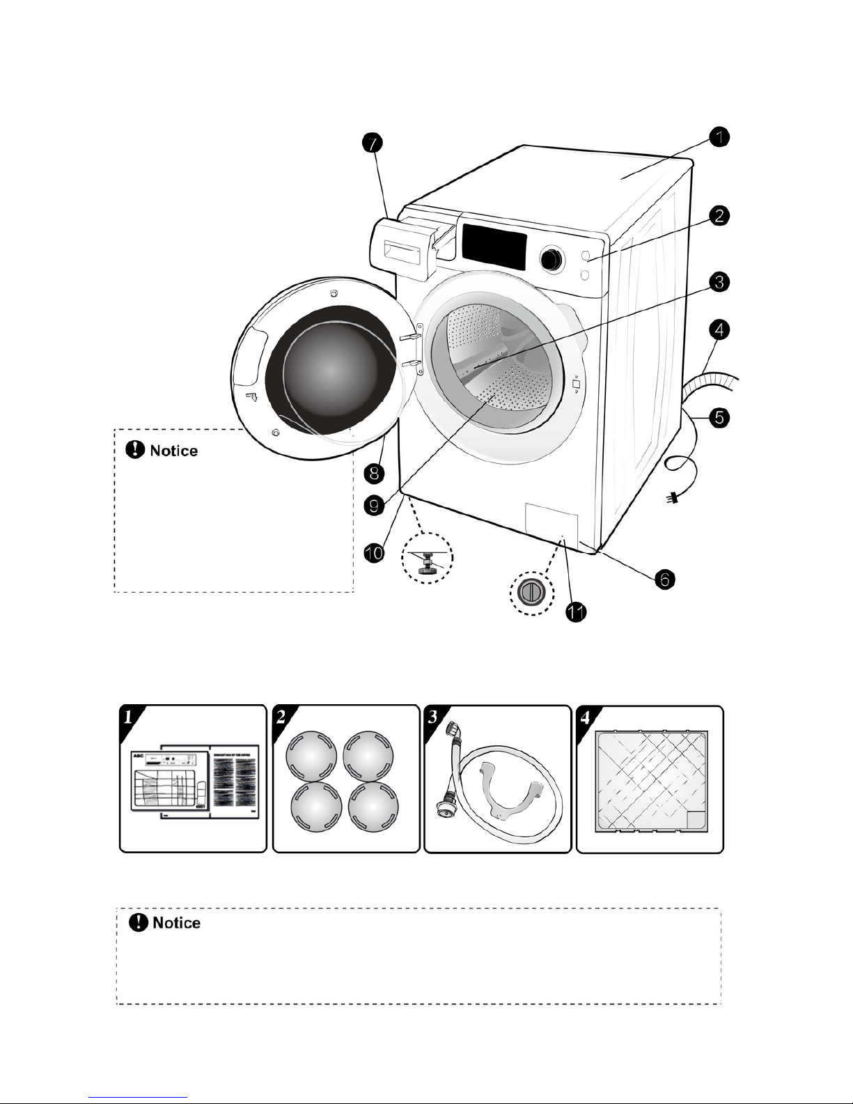
4. PARTS IDENTIFICATION
9
MARKS OF PARTS
1. Top Cover
2. Control Panel
3. Lifter
4. Drain Hose
5. Power Plug
6. Filter Cover Cap
7. Dispenser
8. Door
9. Drum
10. 4 Adjustable
Feet
11. Drain Pump
Filter
As for the product improvement
and expansion in series, products
purchased by you may differ from
the graphical representations in this
manual, the actual product shall
p
revail.
The appearance depends on different machine models
Some models are not equipped with “U” elbow bracket or noise reduce board but not affect
th
e usage,
IFU ASM 4 Plastic Caps Of
Inlet Tube +“U”
Noise Reduce
Board
ACCESSORIES
5. INSTALLATION AND TEST
10
1. Before servicing, ask the customer what the trouble is.
2. Check the setup (power supply is 220-240V AC, remove the transit bolts,
level the washer....).
3. Check with the troubleshooting guide.
4. Plan your service method by referring to the disassembly instructions.
5. Service the unit.
6. After servicing, operate the appliance to see whether it functions correctly.
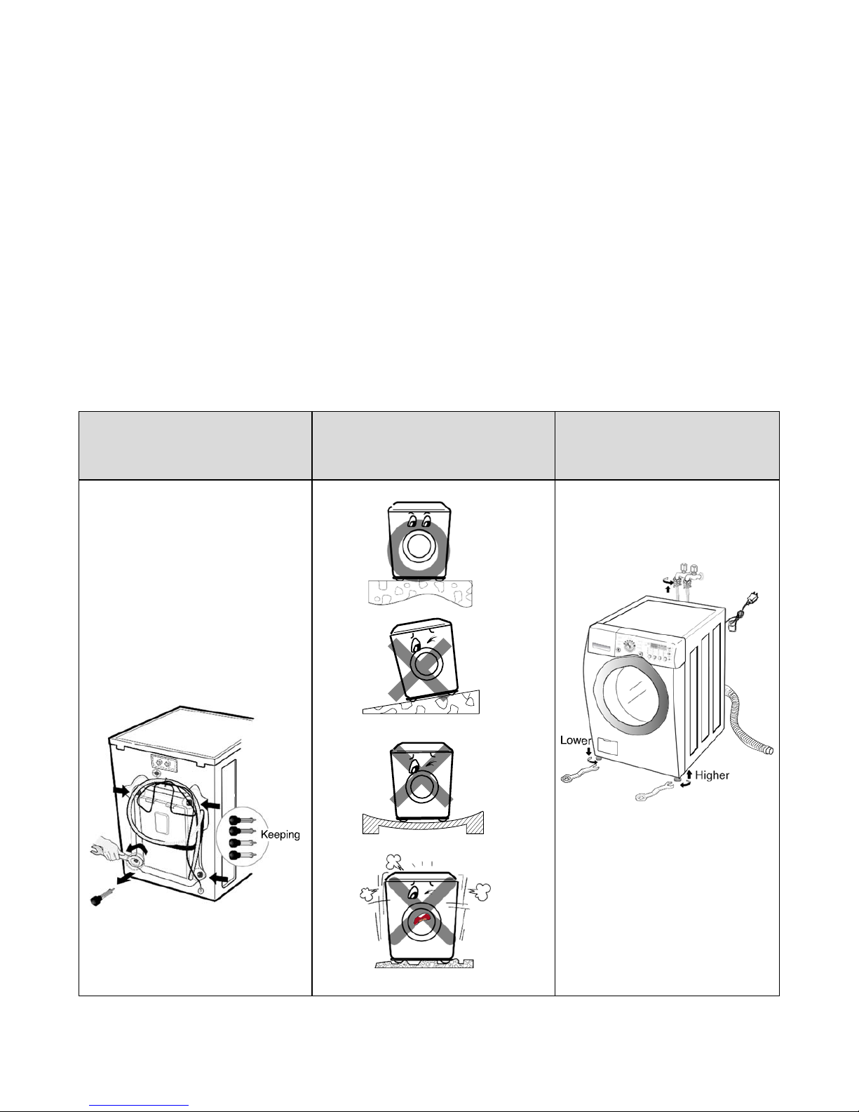
5.1 STANDARD INSTALLATION
REMOVE THE
SHIPPING BOLTS
INSTALL THE APPLIANCE
ON A FLAT AND FIRM
ADJUST THE LEVELING
♦ Remove the 4 shipping bolts with
the supplied wrench.
※Do first lower side to remove
easily.
♦ Keep the shipping bolts and
spanner for future use.
♦ Insert the 4 caps (provided) into the
hole.
♦ Turn the leveling feet to adjust the
appliance.
♦ Turn clockwise to raise;
♦ Turn counterclockwise to lower.
5. INSTALLATION AND TEST
11
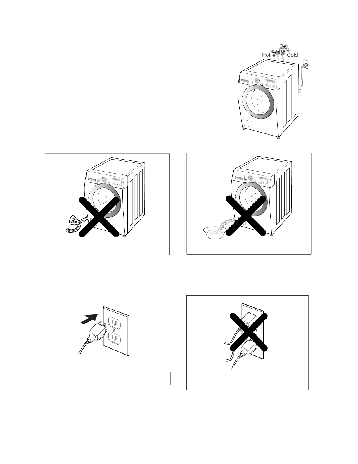
5.2 CONNECT THE INLET HOSE
♦ Verify that the rubber washer is inside of the valve
connector.
♦ Tighten the inlet hose securely to prevent leaks.
5.3 CONNECT THE DRAIN HOSE
※ The end of the drain hose should be placed less than 96” from the floor
5.4 CONNECT POWER PLUG
5.5 TEST OPERATION
Make sure that the hose is not twisted
A
void submerging the end of the hose
Connect the power plug to the wall outlet
·Avoid connecting several electric devices,
as doing so may cause a fire
5. INSTALLATION AND TEST
12
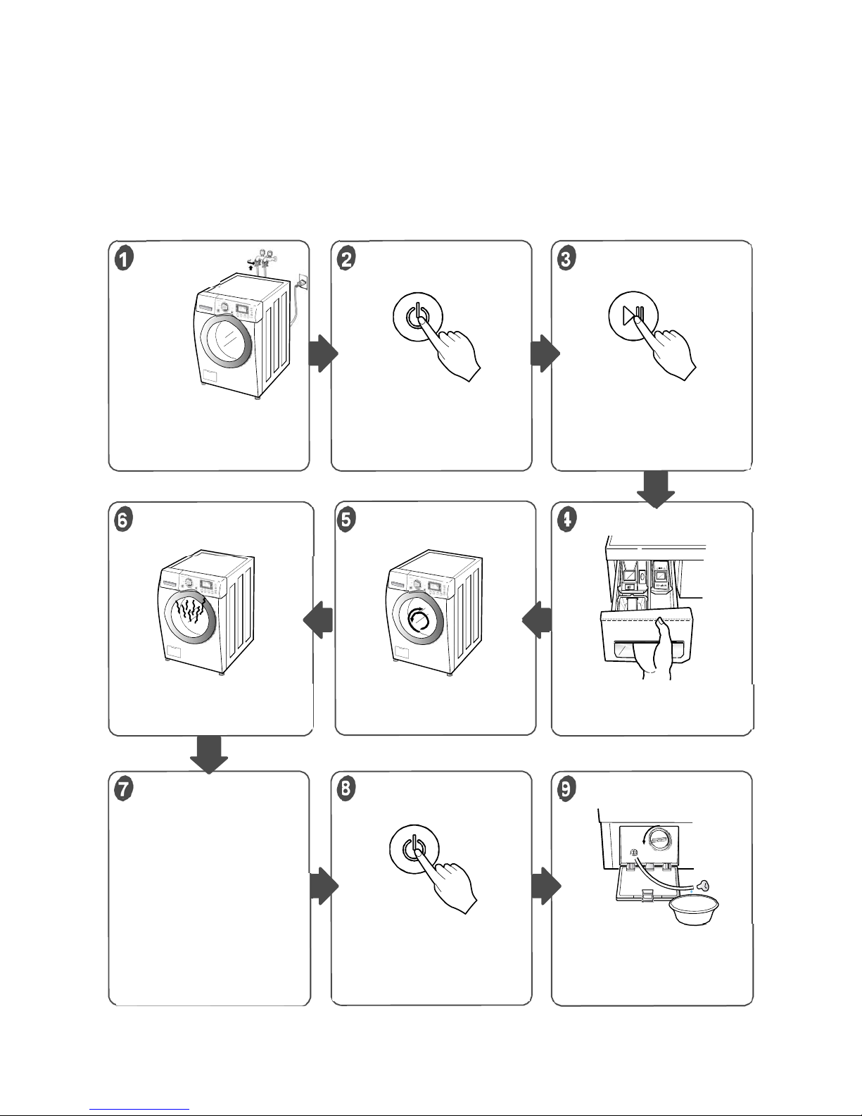
Carry out self-inspection on washing machine as per Figure 8-1 or carry out trial
run as shown in figure below
[CAUTION] Before carrying out inspection in this way, please turn on the special function mode as per
Figure 8-2; after the inspection is finished, please turn off the special function mode, otherwise, it may
lead to mal-operation of users and further affect the normal usage of washing machine.
Select a short program and set
the laundering temperature
above the room tem
p
erature.
6
Connect the power plug to the
outlet.
Connect the inlet hose.
The “door lock icon”on display
screen is on if the door has
locked.
Display the present temperature
as per Figure 8-2
Check if the drum rotates
clockwise and anticlockwise
Check if water is supplied
through the detergent dispenser
During water draining, check
the drain and spin functions.
A
fter the spinning ends, The
“door lock icon”on display
screen is flickering if the door
execute unlocking operation.
The display screen displays
“End”. Press down the
“ON/OFF” button for 3s, and
then turn off the power supply
If service is needed during
check, remove the remaining
water by pulling out hose cap
8
1
2
3
6
5 4
7 9
Check the water supply
Check the automatic
reverse rotation
Check the water heating
function
Check the drain and
Spin functions.
Water removal
Press the “ON/OFF”
button
Press the “ON/OFF”
button
Press the “Start/Pause”
button
Preparation
for washing
6. OPERATION
13
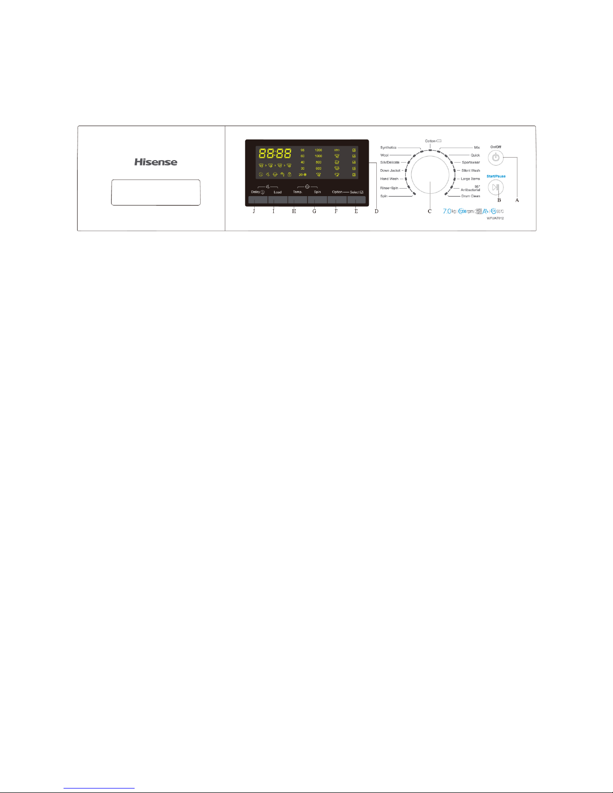
6.1 CONTROL PANEL
A: “ON/OFF” button
Turn on/off the power with this button
B: “Start/Pause” button
Start/ Stop the washer with this button
C: Cycle Selector Knob
Rotate the Cycle selector knob to select the cycle designed for different types
of fabric and soil levels.
D: Display window
Display the information such as the washing program, function, state and
residual time of washer
E: “Select” button
Confirm the selection of additional function of laundering by pressing this
button.
F: “Option” button
Choose the additional function of laundering by repeatedly pressing this
button to switch over from one option to another.
G: “Spin” button

6. OPERATION
14
Change the final spinning speed by repeatedly pressing this button to switch
over from one option to another.
H: “Temp.” button
Change the heating temperature of laundering by repeatedly pressing this
button to switch over from one option to another.
I: “Load” button
Manually select the range of clothes quantity by repeatedly pressing this
button to switch over from one option to another.
J: “Delay” button
This function allows the user to wash clothes at his/her convenience, such as
the time period where the electricity is cheap.
6.2 CYCLE GUIDE
The cycle guide below shows the options and recommended fabric types for
each cycle.
 Loading...