

Page 1

Page 2

Page 3

SAFETY INFORMATION
EMERGENCY DOOR OPENING
INSTALLATION GUIDE
Page 4

SAFETY INFORMATION
1.
The manufacturer reserves the right for any modifications
on the product which might be deemed necessary or
useful without informing about it in this IFU.
2.
Before operating your new washing machine, please read
this instruction carefully, and keep it for future reference. If
you have lost it accidentally, ask customer service for e-
copy or hard copy.
3.
Please make sure the socket is grounded securely, the
water source connection is reliable.
4. This appliance is not to be used by persons (including
children) with reduced physical, sensory or mental
capabilities, or lack of experience and knowledge, unless
they have been given supervision or instruction
concerning use of the appliance by a person responsible
for their safety.
This appliance can be used by children aged from 8
5.
years and above and persons with reduced physical,
sensory or mental capabilities or lack of experience and
knowledge if they have been given supervision or
instruction concerning use of the appliance in a safe way
and understand the hazards involved. Children shall not
play with the appliance. Cleaning and user maintenance
shall not be made by children without supervision.
6.
Children should be supervised to ensure that they do not
play with the appliance.
7.
If the supply cord is damaged, it must be replaced by the
manufacturer, its service agent or similarly qualified
persons in order to avoid a hazard.
8.
The new hose-sets supplied with the appliance are to be
used and that old hose-sets should not be reused.
1
Page 5

9.
For appliances with ventilation openings in the base, that a
carpet must not obstruct the openings.
10.
Children of less than 3 years should be kept away unless
continuously supervised.
11.
The maximum permissible inlet water pressure, 1 MPa, for
appliances intended to be connected to the water mains.
The minimum permissible inlet water pressure, 0.1 MPa, if
this is necessary for the correct operation of the appliance.
12.
The maximum washing capacity is 7.5/8.5
For private domestic use only.
13.
/9.5/10kg.
14.
2
Page 6

ensure
2. Remove transport bolts
Important: Transport bolts which are not removed can cause damage to
the appliance.
Screw off all transportation bolts for approx. 30mm with wrench following the
direction of arrow shown (not fully screw it off).
30
Push four transportation bolts on horizontal direction inward and loose
transportation bolt.
3
Page 7

Pull out transportation bolt together with rubber part and plastic part.
To ensure safety and reduce noise, you should install the transportation bolt
cover supplied with the unit (see the annex accompanying the unit). Lean
and place the transportation bolt into hole and press it following the shown
direction until it clicks.
Adjustment of the feet
3.
The appli
ance must be installed on a solid and level floor surface (if necessry
use a spirit level). If the appliance is to be installed on a wooden floor, distribute
the weight by placing it on a 60x60cm sheet of plywood at least 3cm in
thickness and secure it to the floor. If the floor is uneven, adjust the 4 leveling
feet
as required; do not insert pieces of wood etc. under the feet.
4
Page 8

4. Install bottom cover
To realize quieter operation, a bottom cover is supplied with the unit (only
applies to some of the Hisense washers). After installing the cover at the
bottom of the washer, the noise level will be greatly reduced. Please ask
for advice from specialists before installing the cover, nevertheless, the
machine can be used without the bottom cover.
Noise-Reduction Bottom Plate Installation Instructions
A:
Stick acoustic wool to the side of bottom cover plate
with the letter of “PUMP”.
Tilt the washer by 30°-40°, when installing the bottom
cover, please face the side with sound insulation
upwards and attach 'PUMP' at the corner of the cover
to the position of the pump in the washer.
PUMP
PUMP
5
Page 9

B:
Right-angle impression
Before installing the noise-reduction bottom
plate, align and paste the acoustic absorption
wool with and along the right-angle impression
on bottom plate (this procedure is unnecessary
for some of the models without acoustic
absorption wool).
Incline the machine to an angle of 40° and let
the side with right-angle notch face towards
front of the washing machine, as shown in the
figure. Insert the side with oblique-angle notch
Pump
between two foot screws at back of the
washing machine completely in place. Then,
install the bottom plate and ensure that it
contacts with bottom of the washing machine
closely.
Remove surface paper on
double sided tape at four sides
of the bottom plate.
Double sided tape
Press the double sided tape
on four sides manually to
secure the noise-reduction
palte to the machine body
firmly.
5. Connect the water supply inlet hose
If the water inlet hose is not already installed, it must be screwed to the
appliance.The blue marked hose is only for cold water. Depending on the model,
the hot water hose marked with red should also be connected, for models having
dual inlets.
6
Page 10
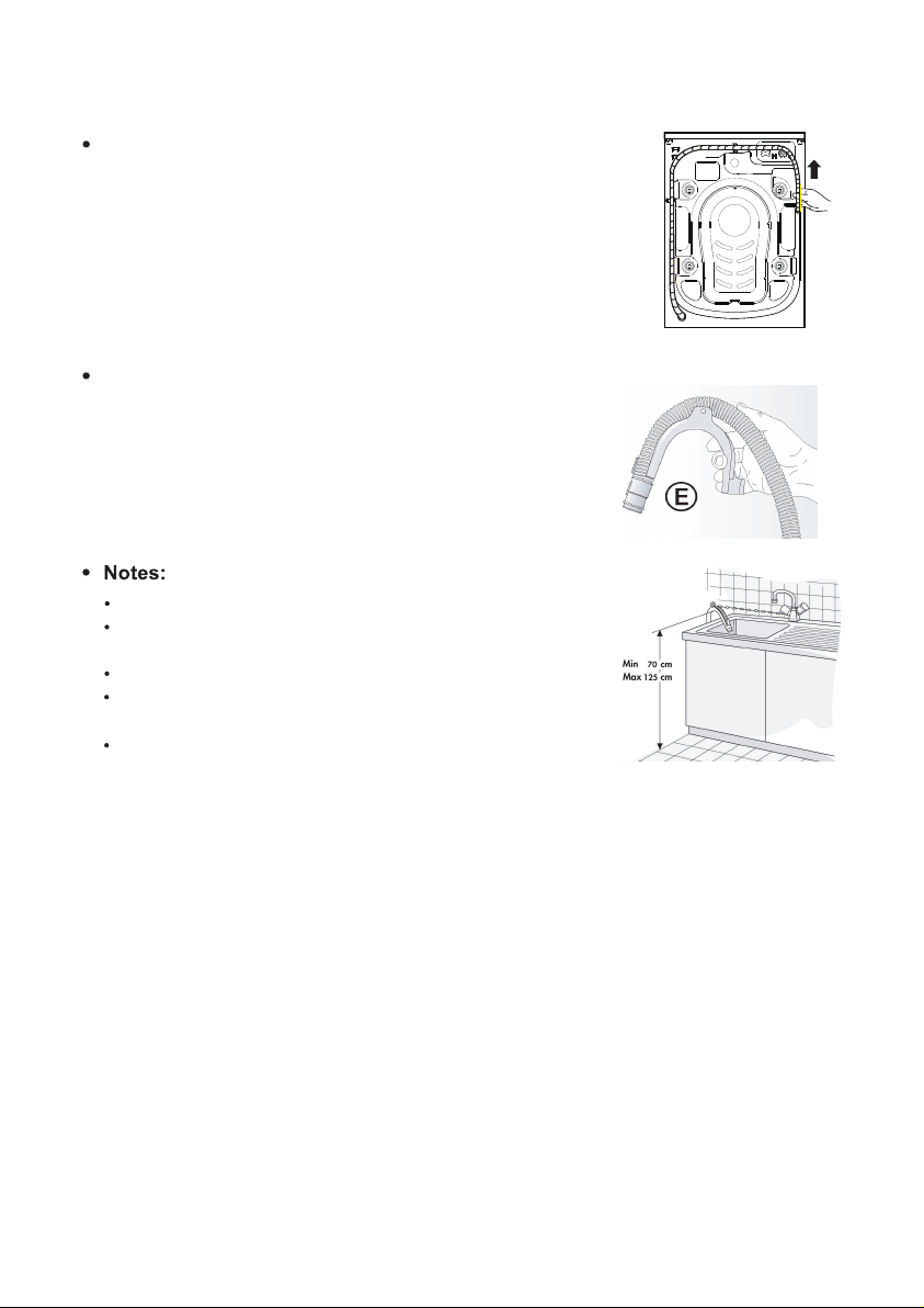
6. Connect the drain hose
In case the drain hose is installed as shown below:
Unhook it only from the right clip (see arrow)
Connect the drain hose to the Drain or hook it over
the edge of a sink by means of the "U" bend.
Fit the “U” bend show in E, if not already installed, if
it at the end of the drain hose.
Ensure that there are no kinks in the drain hose.
Secure the hose so that it cannot fall down. After
wash phase, machine will drain out hot water.
Small hand basins are not suitable.
To make an extension use a hose of the same type
and secure the connections with clips.
Max. Overall drain hose length: 2.50 m.
7
Page 11
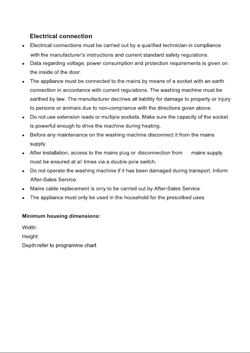
7.
the
615 mm
855 mm
8
Page 12
that
The symbol on the product, or on the documents accompanying the product,
indicates that this appliance may not be treated as household waste. Instead it
shall be handed over to the applicable collection point for there cyclingof electrical
and electronic equipment. Disposal must be carried out in accordance with local
environmental regulations for waste disposal. For more detailed information about
treatment, recovery and recycling of this product, please contact your local city
office, your household waste disposal service or the shop where you purchased
the product.
from the mains supply,
the mains.
en
,
the
9
Page 13
Clean the outside of the washing machine with a damp cloth. Do not use abrasive
detergents.
Never open the door forcibly or use it as a step.
DESCRIPTION OF THE WASHING MACHINE
Control panel layout and
appearance will depend on the model.
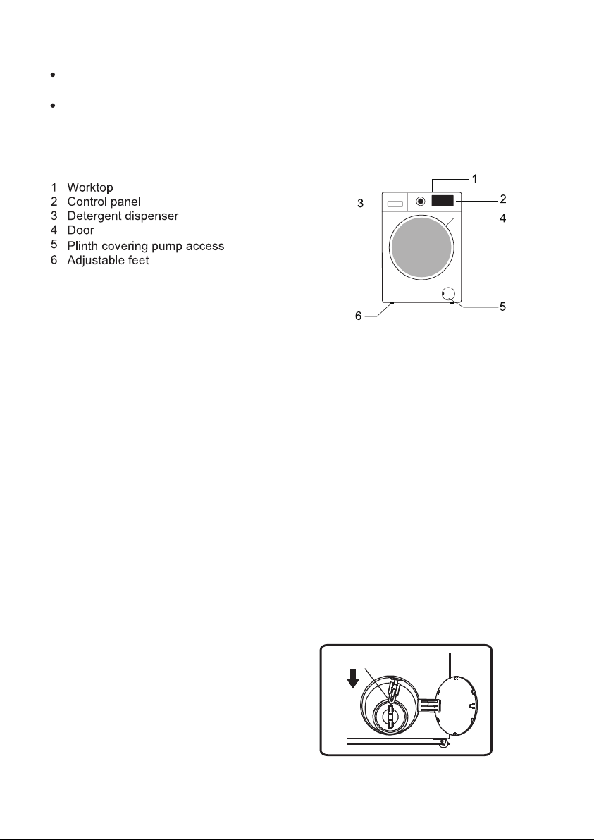
EMERGENCY DOOR OPENING
In case of failure to open the door due to power outage or other special
circumstances, the door lock lever at the drainage pump door can be used for
emergency opening.
Note:
1. Do not operate when the machine is working normally;
2. Before operation, please make sure that the inner barrel has stopped turning,
without high temperature, and the water level is lower than the clothing inlet. If the
water level is higher than the clothing inlet, drain off water through the drain-away
pipe (if available) or by slowly unscrewing the filter.
3. Operation method: Open the cover of drainage pump door, pull down the lock
lever with the help of a tool, and then the door can be opened(indicated in the figure).
10
Door lock lever
Page 14
BEFORE THE FIRST WASH CYCLE
To remove any residual water used during testing by the manufacture r, we
recommend that you carry out a short wash cycle without laundry.
1 Open the tap.
2 Close the door.
3 Pour a little detergent (about 30 ml) into the main wash chamber of the deter gent dispenser .
4 Select and start a short programme (see separate quick reference guide).
PREPARATION OF THE WASHING
1.
Sort the laundry according to...
Type of fabric / care label symbol
Cottons, mixed fibres, easy care/synthetics, wool, handwash items.
Colour
Separate coloured and white items. Wash new coloured articles separately.
Loading
Wash items of different sizes in the same load to improve washing efficiency and
distribution in the drum.
Delicates
Wash small items (e.g. nylon stockings, belts etc.) and items with hooks (e.g. bras)
in a cloth bag or pillow case with zip. Always remove curtain rings or wash curtains
with the rings inside a cotton bag.
2. Empty all pockets
Coins, safety pins etc. can damage your laundry as well as the appliance drum and
tub.
3. Fasteners
Close zips and fasten buttons or hooks; loose belts or ribbons should be tied
together.
4.
Stain removal
Blood, milk, eggs etc. are generally removed by the automatic enzyme phase of the
programme.
11
Page 15
Dyeing
Loading the laundry
Open the door.
U
.
12
Page 16
/ soak
"A or B"
A
13
B
Page 17
unds
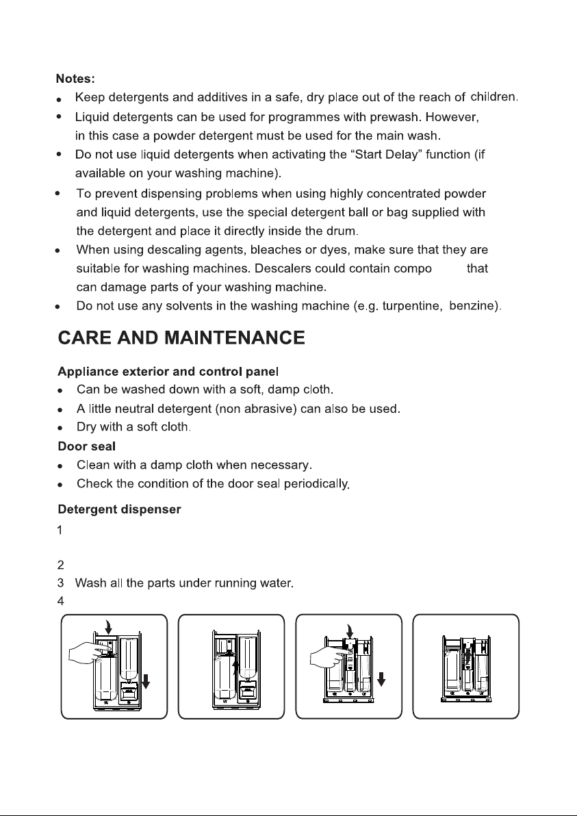
Press the release lever in the main wash compartment downward and remove
the drawer(fig.“B or D
”).
Remove siphon in softener slot. (fig.“C or E”).
Refit the siphon in the detergent drawer and fit the drawer back inside its housing.
B
C
D
E
14
Page 18
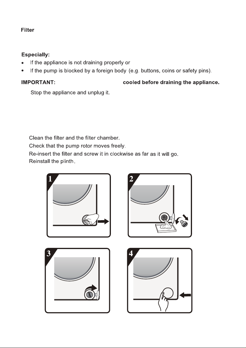
We recommend that you check and clean the filter regularly, at least two or three
times a year.
if it fails to perform spin cycles.
Ensure that the water has
1
2 Insert removal tool like slotted screwdriver into the small opening of bottom
baffle, press the bottom baffle downward with much strength and open it.
3 Put a flat container under filter door and then drain with emergency drain pipe
(see [draining residual water] for specific operation methods). Then, loosen
filter anticlockwise and completely unscrew and remove the filter.
4
5
6
7
15
Page 19
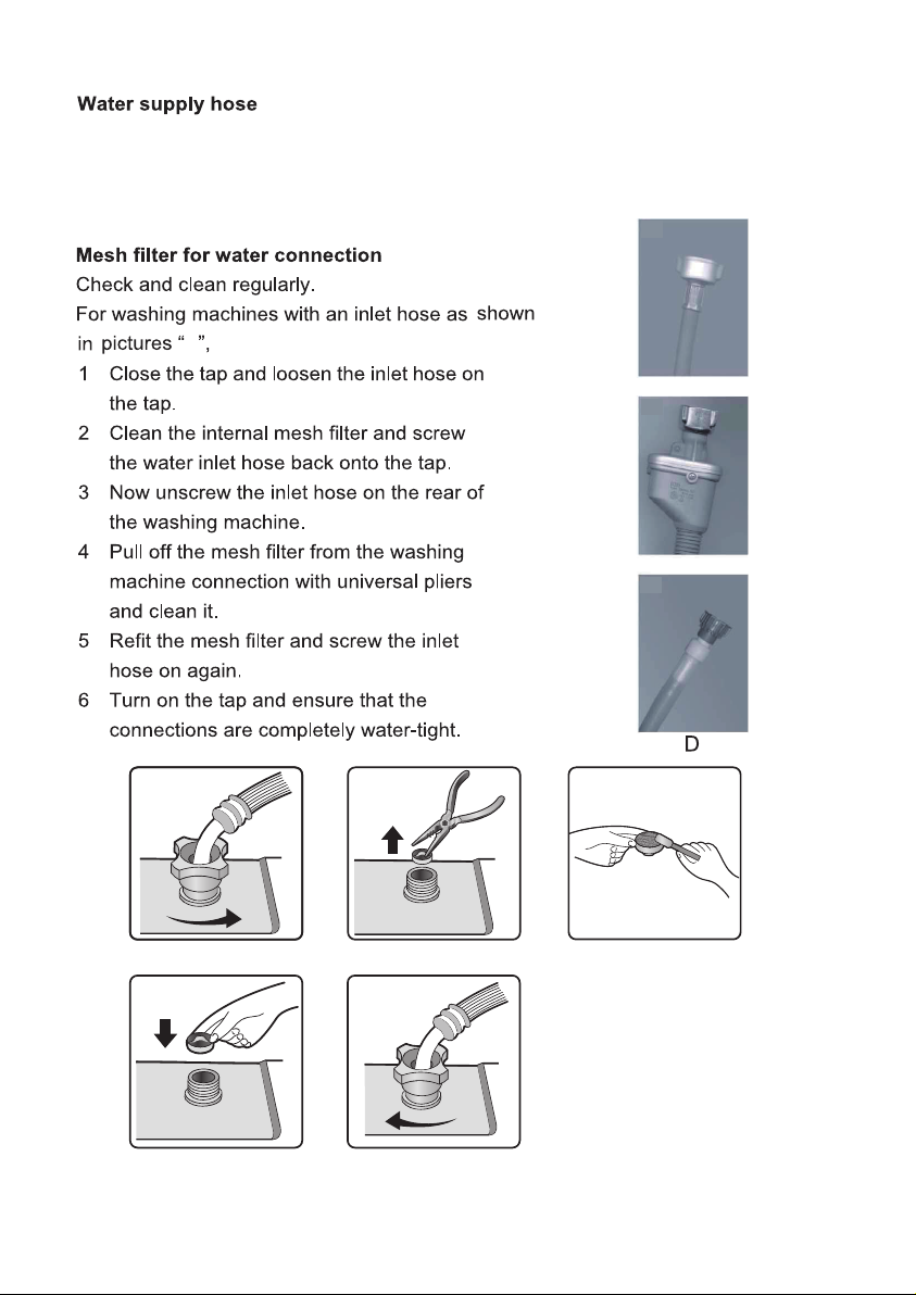
Check the supply hose regularly for brittleness and cracks and replace it if
necessary using a new hose of the same type(available from After-Sales Service
or specialist dealer).
D
16
Page 20
too
solv
17
Page 21
18
remove some
Page 22
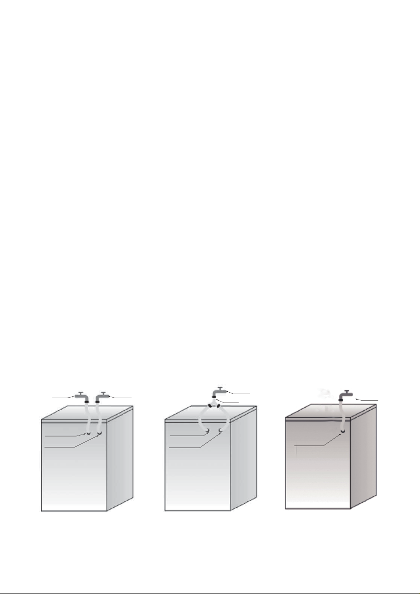
Hot / Cold fill fault - For Models with Dual Inlets
If you wish to connect hot and cold water supply (Fig.1):
1. Fix the red marked inlet hose to the hot water tap and to the inlet valve with the red
filter on the rear side of machine.
2. Fix the other inlet hose to the cold water tap and to the inlet valve with the blue filter
on the rear side of the machine.
Make sure:
a) The connections are tightly fixed
b) Do not invert their position (for example: cold fill into hot inlet valve and vice versa).
If you wish to connect only the cold fill follow the below instructions (Fig. 2):
1. You will need a Y-piece connector. This can be purchased from local hardware or plumb
ing supplier.
2. Fix the Y-piece connector to the cold fill tap.
3. Connect the two inlet valves present on the rear part of the machine to the Y-piece
connector using the hoses provided.
For Models with Single Inlet
Fix the inlet hose to the cold water tap and to the inlet valve on the rear side of the machine
as (Fig. 3).
Ensure that:
All connections are tightly fixed.
Do not allow children to operate, crawl on, be near or inside your washer.
Note that during the wash cycles, the surface temperature of the porthole door may
increase.
Close supervision of children is necessary when the appliance is used near children.
Hot
fill
Red inlet
valve
Blue inlet
valve
Fig.1
Cold
fill
Red inlet
valve
Blue inlet
valve
Fig.2
Ypiece
Cold
fill
Inlet
valve
Fig.3
Cold
fill
19
Page 23
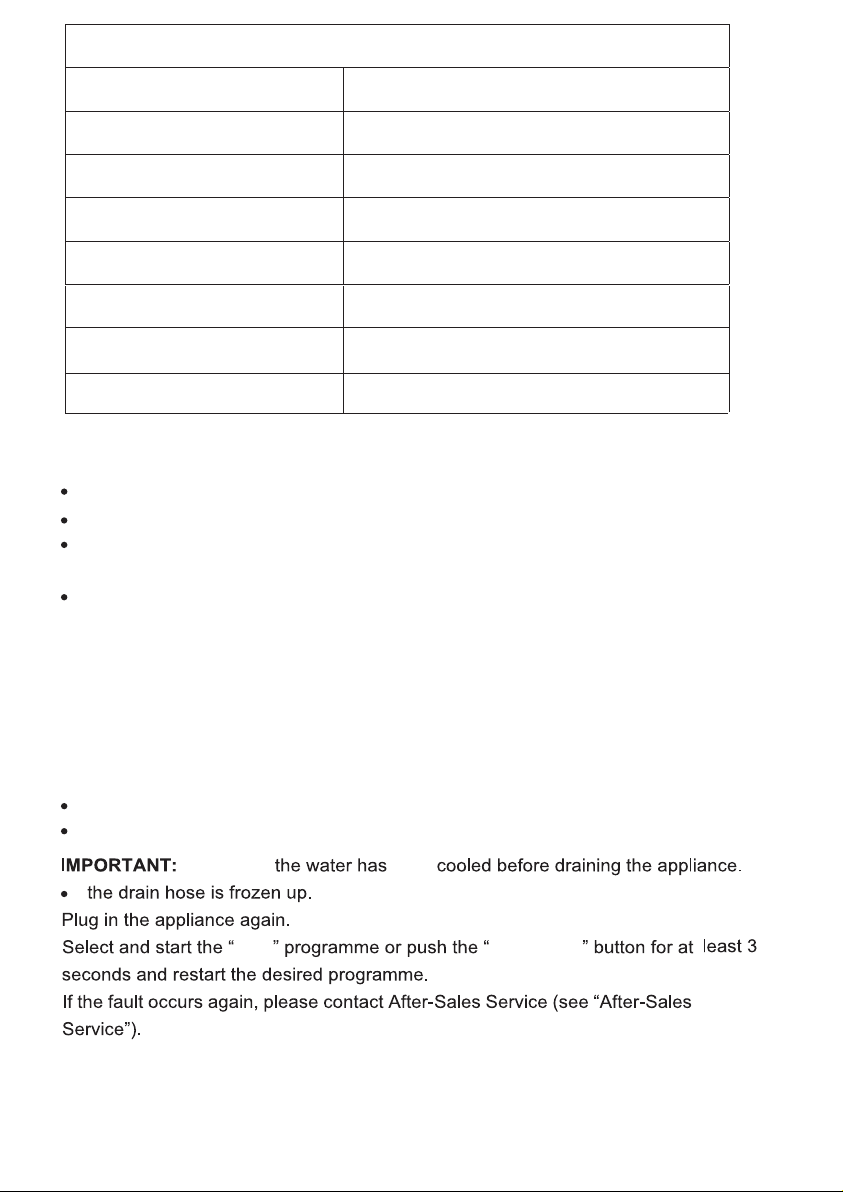
Fault Code List
Displayed on Display Window Fault Description
“F01” Water inflow fault
“F03” Drainage fault
“F13” Door lock fault
” Door unlock fault
“F14
F24”
“
verflow or too much foam.
O
else
“U
code, “F04-F98”
fault
nb”
Electronic module fault
Unbalance alarm
.
a. “F01” displayed on screen
The machine is not fed with water or insufficient water. Check:
Faucet is fully open and has enough water pressure.
Water inlet pipe is knotted or not.
Filtering net of water inlet pipe is blocked or not (refer to maintenance and
repair).
Water pipe is frozen or not.
Press “Start/Pause” key after fault is removed.
If fault occurs again, please contact after-sale service (refer to after-sale
service.).
b. “F03” displayed on screen
The washer is not emptied. The washer stops the program being executed. Shut
down the machine and disconnect power supply. Check:
Drain pipe is knotted or not.
Filter in drain pump is blocked or not (refer to the cleaning of filter in drain pump)
Ensure that
been
Spin
Start/Pause
20
Page 24

C. Fault code
The washer stops when the program is running. The display window shows
fault code “F13”, “F14”, “F24”, else fault codes from “F04” to “F98” or “Unb”.
If fault code “F13” is shown
Door lock is abnormal. Start program for 20 sec and unlock the washer door
(PTC) to check whether the door is closed.
Open or close it again.
After fault is removed, press “Start/Pause” key. If fault occurs again, disconnect
power supply and contact after-sale service.
If fault code “F14” is shown
Door open fault.
Action: Press “Start/Pause” button. The washing machine will try to make the door
open. The alarm will not be removed until the door is unlocked. Or, turn the nub to
Off for 3 seconds to turn off the machine. Choose the desired programmme to start
the machine. The alarm will be removed.
If fault code “F24” is shown
Water level reaches overflow level.
Remove it by pressing “Start/Pause” key and feed water.
Select and start required program. If fault occurs again, disconnect power supply and
contact after-sale service.
If else fault code “F04” to “F98” is shown
Electronic module fails.
Turn the nub to Off for 3 seconds to turn off the machine.
After fault is removed, press “Start/Pause” key. If fault occurs again,
disconnect power supply and contact after-sale service.
nb” is shown
Unbalance alarm shall be solved by the following methods
1.Laundry winding
Turn the knob to “off” for 3 seconds for shutdown, open the door, shake the clothes and
put them back into the washing machine, then select the single dewatering program to
dry again.
2.Too light-weighted laundry
Turn the knob to “off” for 3 seconds for shutdown, open the door, put in one or two
towels, and then select the single dewatering program to dry again.
21
Page 25
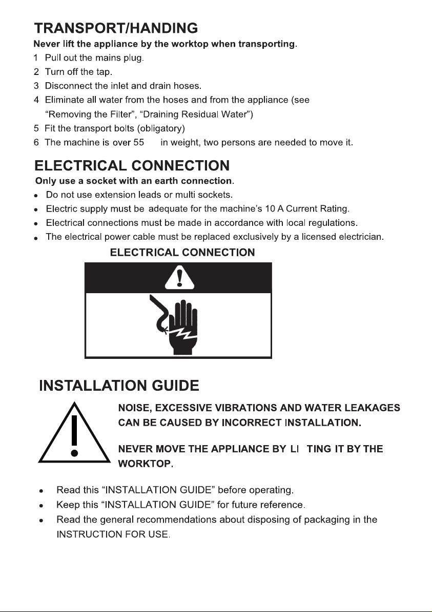
kg
22
F
Page 26
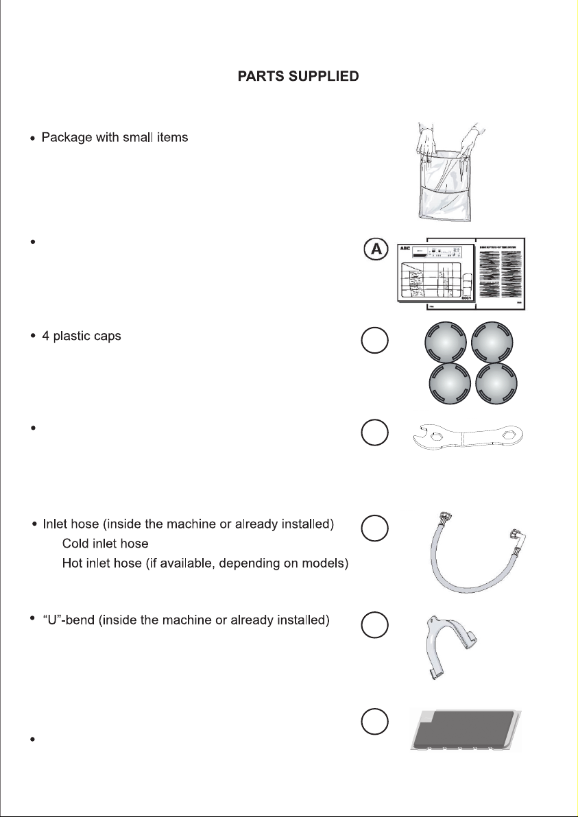
Instruction for use, installation guide, warranty card
(depends on model)
B
Wrench
Bottom cover(depends on model)
C
D
E
F
23
Page 27

2256485-X08061280A
 Loading...