

Page 1
TFT LCD Preliminary Specification
MODEL NO.:HC420EF-C22
Approved by:
Note:
Customer:
Approved By Date:
Reviewed By Date:
Prepared By Date:
1
Page 2
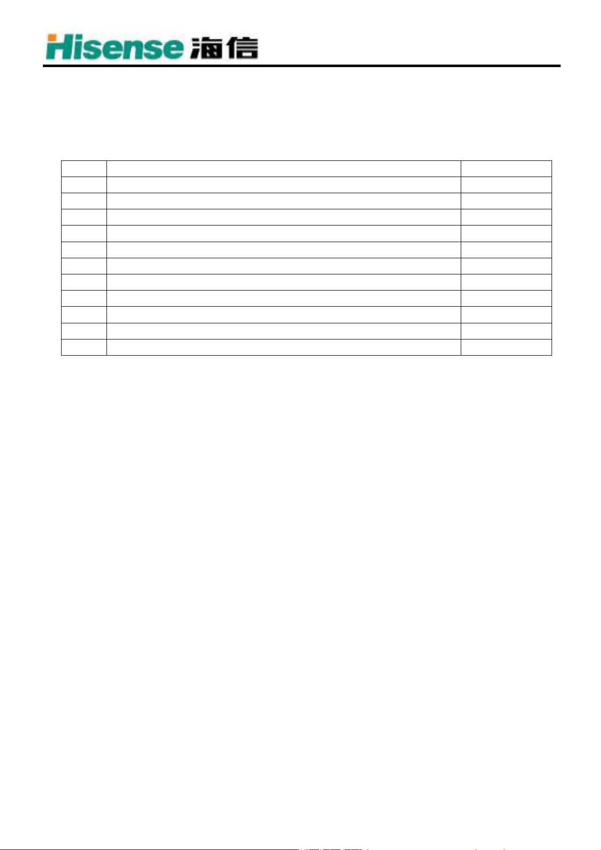
CONTENT
NO. ITEM PAGE
CONTENT 2
DESCRIPTION 3
1 ABSOLUTE MAXIMUM RATINGS 4
2 INITIAL OPTICAL CHARACTERISTICS 5
3 ELECTRICAL CHARACTERISTICS 8
4 BLOCK DIAGRAM 11
5 INTERFACE PIN ASSIGNMENT 12
6 INTERFACE TIMING 19
7 MECHANICAL CHARACTERISTICS 22
8 PACKAGING 24
9 PRECAUTIONS 26
2
Page 3

DESCRIPTION
The following specifications are applied to the following Hisense module.
Product Name: HC420EF-C22
General Specifications
Effective Display Area :(H)930.24×(V)523.26 (mm)
Number of Pixels :(H)1920×(V)1080 (Pixels)
Pixel Pitch :(H)0.1615×(V)0.4845 (mm)
Color Pixel Arrangement : R+G+B Vertical Stripe
Display Mode : Transmissive Mode
Normally Black Mode
Top polarizer Type : Anti-Glare
Number of Colors : 16.7M (colors)
Viewing Angle Range : Viewing angle free
R/L 176 (Typ.), U/D 176 (Typ.) (CR≥20)
Back Light : 12 CCFL
External Dimensions :(H)983.0×(V)576.0×35.1 (mm)
Weight : 11.5 (Kg)
3
Page 4
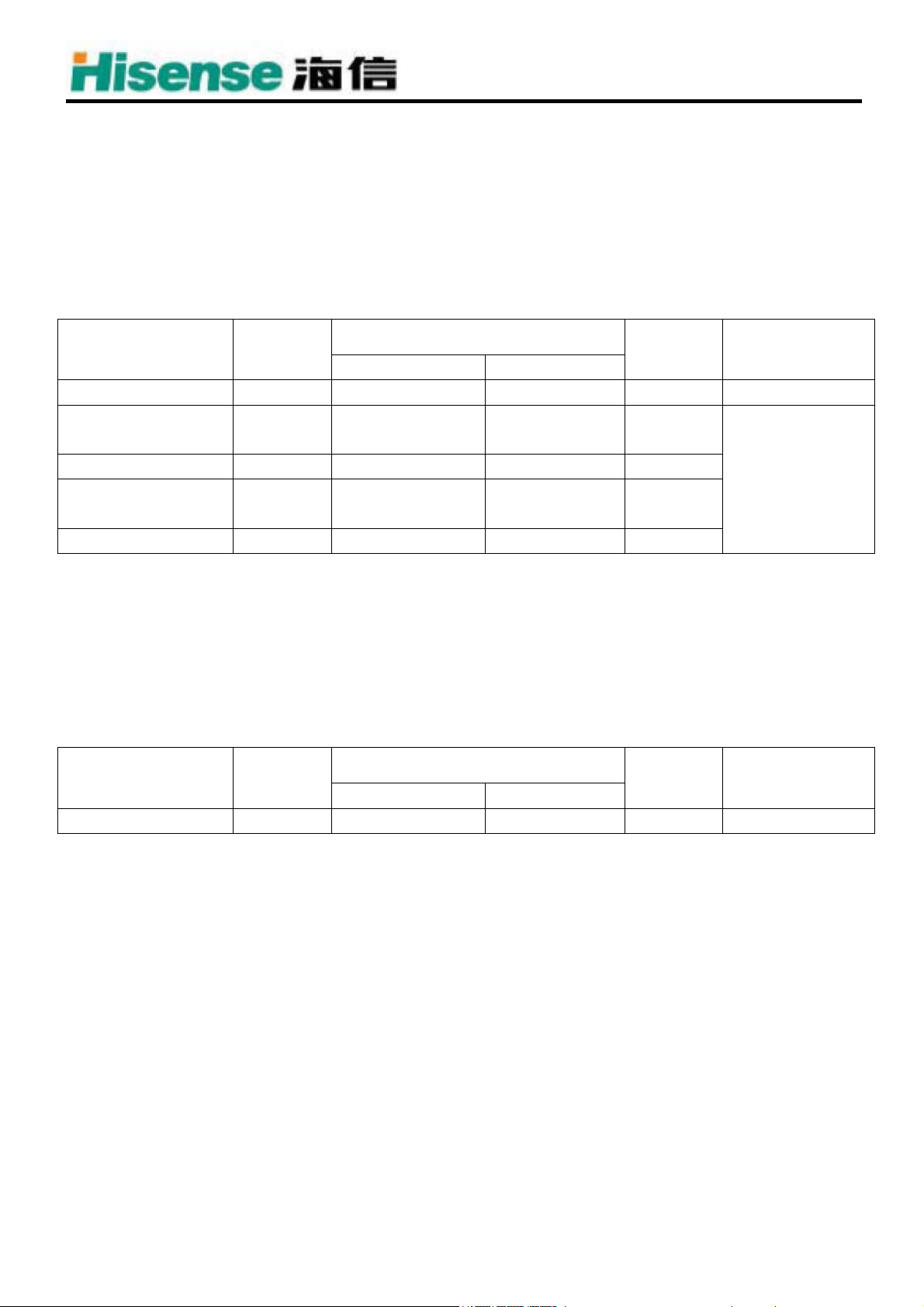
1. ABSOLUTE MAXIMUM RATINGS
1.1 Electrical Absolute Maximum Ratings
The following items are maximum values which, if exceeded, may cause faulty operation or damage to
the LCD module.
(1)TFT Module
Table 1. ABSOLUTE MAXIMUM RATINGS
Parameter Symbol
Unit Note
Min. Max.
Power input Voltage V
Operating
Temperature
-0.3 14.0 V [DC] at 25±2℃
LCD
TOP 0 50 ℃
Storage Temperature TST -20 60 ℃
Note 1,2
Operating Ambient
Humidity
HOP 10 90 %RH
Storage Humidity HST 10 90 %RH
Notes : 1) Temperature and relative humidity range are shown in the figure below.
Wet bulb temperature should be 39 °C Max. and no condensation of water.
2) Gravity mura can be guaranteed under 40℃ condition.
1.2 BACKLIGHT UNIT
Table 2. BACKLIGHT UNIT
ITEM Symbol
Unit Note
Min. Max.
Lamp Voltage Vw - 3000 VRMS
4
Page 5
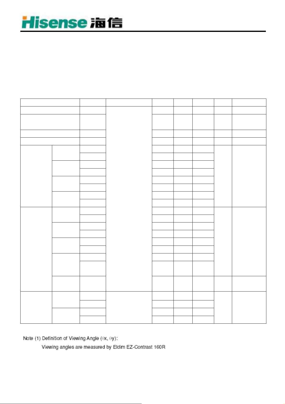
2. INITIAL OPTICAL CHARACTERISTICS
The following optical characteristics are measured under stable conditions. It takes about 30 minutes to
reach stable conditions. The measuring point is the center of display area unless otherwise noted. The
optical characteristics should be measured in a dark room or equivalent state.
Measuring equipment:SR-3 and LIPS
Ambient Temperature=25±2°C, V
Table 3. OPTICAL CHARACTERISTICS (TBD)
ITEM SYMBOL CONDITION Min. Typ. Max. UNIT NOTE
Contrast CR
Response Time
Brightness of white Bwh - 450 - Cd/m2
Brightness uniformity Buni - - % 4)
Red
Color
Chromaticity
(CIE)
Variation of
Color
Position
(CIE)
Green
Blue
white
Red
Green
Blue
white
Color
Gamut
Gray to
gray
x 0.6382
y 0.3228
x 0.2934
y 0.6012
x 0.1471
y 0.0537
x 0.2921
y 0.2998
Δx - - 0.04
Δy - - 0.04
Δx - - 0.04
Δy - - 0.04
Δx - - 0.04
Δy - - 0.04
Δx - - 0.04
Δy
C.G 72 % NTSC
=12.0V, fV=60Hz, Dclk=74.25MHz V
LCD
2000 6000 - - 2)
- 6.5 ms 3)
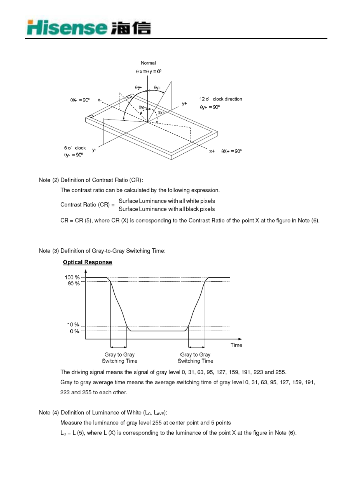
θx=0°, θy=0°
viewing angle at
normal direction
1)
- - 0.04
=1.65V, EXTV
BR_A
=100%
BR_B
-
-
[Gray
scale=255]
[Gray
scale=255]
5)
Viewing
Angle
Horizontal
Vertical
θx+
θx- 88
θy+ 88
θy- 88
CR≥20
88
Deg. Note (1)
5
Page 6
6
Page 7
7
Page 8
3. ELECTRICAL CHARACTERISTICS
3.1 TFT-LCD Module
Table4. ELECTRICAL CHARACTERISTICS
8
Page 9

9
Page 10

3.2 Back Light Unit
CCFL(Cold Cathode Fluorescent Lamp) CHARACTERISTICS(Ta=25℃±2℃)
Parameter Symbol
Min. Typ. Max.
Lamp Voltage Vw 900 1050 1100 VRMS
Lamp Current(HI-Side) IL 9.5 10.5 11.5 mA
- - 1500 0℃ V
Lamp Starting Voltage Vs
- - 1300 25℃ V
Operating Frequency Fo 40 60 80 kHz
Lamp Life Time LBL 50,000 Hour
Value
Unit Note
3.3 Electrical specification
Parameter Symbol
Min. Typ. Max.
Power Consumption PBL 135 W
Power Supply Voltage VBL 90.0 220.0 264.0 V AC
Power Supply Current IBL 0.62 A
Oscillating Frequency FW 41.0 43.0 45.0 KHZ
Dimming Frequency FB 200 210 220 HZ
Minimum Duty Ratio DMIN 50 %
Value
Unit Note
10
Page 11

4. BLOCK DIAGRAM
4.1 TFT Module
4.2 Back Light Unit
11
Page 12

5. INTERFACE PIN ASSIGNMENT
5.1 TFT-LCD MODULE
Table 5. MODULE CONNECTOR(CN1) PIN CONFIGURATION
12
Page 13

13
Page 14

5.2 POWER UNIT
5.2.1 XP802 : TJC10-14A
NO. NAME FUNCTION
1-2 M5V MAIN 5V
3-4 GND GND
5 SW 背光源开关信号(高电平开)
6 BRI 调光信号
7 GND GND
8-9 12V 12V
10-11 S5V 待机 5V
12 STB 待机信号(高电平开机)
13-14 GND GND
14
Page 15

5.2.2 XP809 : TJC10-13
NO. NAME FUNCTION
1-2 14V 伴音 14V
3-4 GND GND
5 12V 12V
6 GND GND
7 M5V 主 5V
8-9 GND GND
10-11 M5V 主 5V
12-13 GND GND
5.2.3 XP901 : TJC10-4A
NO. NAME FUNCTION
1 GND GND
2 Isen 灯管电流反馈
3 PS 灯管高呼信号
4 GND GND
15
Page 16

5.2.4 XP900 : TJC10-14A
NO. NAME FUNCTION
1-5 TA 逆变交流输出 A
6 NC 空脚
7-8 GND GND
9 NC 空脚
10-14 TB 逆变交流输出 A
5.2.5 XP801 : VH-3A-2
NO. NAME FUNCTION
1 L 交流电源输入
2 N 交流电源输入
16
Page 17

5.3 RELATIONSHIP BETWEEN DISPLAY COLORS AND INPUT SIGNALS
The brightness of each primary color(red,green,blue) is based on the 10-bit gray scale data input for the
color. The higher binary input, the brighter the color. Table 6 provides a reference for color versus data
input.
Table 6. COLOR DATA REFERENCE
17
Page 18

5.4. Signal Timing Specifications
Table 7 shows the signal timing required at the input of the LVDS transmitter. All of the interface signal
timing should be satisfied with the following specification for normal operation.
18
Page 19

6. INTERFACE TIMING
6.1 Signal Timing Waveforms
19
Page 20

6.2 LVDS INTERFACE
20
Page 21

21
Page 22

7. MECHANICAL CHARACTERISTICS
69.70
B
20.00
23.10
27.00
共四处
4-?5.00
14.00
共两处
A
11.00
200.00
310.00±0.5
576.00±1
566.00±0.8
200.00±0.5
B
1:1
比 例
共 页
质量
A0
第 页
阶段标记
青岛海信电器股份有限公司
幅面:
材料
HC420EF_C22
assy module
签名 日期
更改单号
B
NOTE:
2. SCREW B:M4,PICTH=0.7/MACHINE,MAX.TORQUE=9kgf-cm,MAX DEPTH=8mm.
4. SCREW D:M4,PICTH=0.7/MACHINE,MAX.TORQUE=9kgf-cm,MAX DEPTH=4.5mm.
3. SCREW C:M4,PICTH=0.7/MACHINE,MAX.TORQUE=9kgf-cm,MAX DEPTH=4.5mm.
5. SCREW E:M3,PICTH=0.5/MACHINE,MAX.TORQUE=9kgf-cm,MAX DEPTH=3.5mm.
1. SCREW A:M4,PICTH=0.7/MACHINE,MAX.TORQUE=9kgf-cm,MAX DEPTH=8mm.
30.00
14.00
11.00
A
数量
批 准
审 核
设 计
标准化
工 艺
电 路
更改标记
制图:
670.00±0.5
6-27.00
25.70
135.00±0.5
440.00±0.5
35.10±1
A
?
7
.
0
0
A
230.00±0.5
A
A
A
983.00±1
973.00±0.8
930.24 DISPLAY AREA
939.00±1 BEZEL OPENING AREA
531.00± BEZEL OPENING AREA
523.26 DISPLAY AREA
0
0
.
5
?
0
0
.
5
?
4
69.70
14.00
4-23.10
6-27.00
B
200.00±0.5
11.00
共两处
566.00±0.8
440.00±0.5
310.00±0.5
4-20.00
11.00
14.00
B
200.00±0.5
600.00±0.5
973.00±0.8
0
0
.
5
?
17.60
10.80
共四处
B
A
280.00±0.5
670.00±0.5
440.00±0.5
230.00±0.5
740.00±0.5
AA
A
4-30.00
A
6-27.00
4-23.10
30.00
35.10±1
22
签名
媒体编号
旧底图总号
格式(1)
底图总号
日期
Page 23

1:1
比 例
共 页
质 量
A0
第 页
阶段标记
青岛海信电器股份有限公司
幅面:
HC420EF_C22
assy module
材料
签名 日期
更改单号
数量更改标记
批 准
标准化
工 艺
审 核
设 计
电 路
制图:
4. SCREW D:M4,PICTH=0.7/MACHINE,MAX.TORQUE=9kgf-cm,MAX DEPTH=4.5mm.
2. SCREW B:M4,PICTH=0.7/MACHINE,MAX.TORQUE=9kgf-cm,MAX DEPTH=8mm.
3. SCREW C:M4,PICTH=0.7/MACHINE,MAX.TORQUE=9kgf-cm,MAX DEPTH=4.5mm.
5. SCREW E:M3,PICTH=0.5/MACHINE,MAX.TORQUE=9kgf-cm,MAX DEPTH=3.5mm.
1. SCREW A:M4,PICTH=0.7/MACHINE,MAX.TORQUE=9kgf-cm,MAX DEPTH=8mm.
E
E
E
2
74.00
-
?
4
.
32.00
11.00
2-12.00
C
C
CC
E
2-172.50
C
C
3-420.00
E
2-172.51
C
C
C
C
C
C
2-8.50
3-6.50
E
C
2-92.55
3-250.00
235.00
3-15.00
E
688.00
360.00
2-540.00
E
3-133.00
C
C
2-275.00
C
3-482.50
C
C
C
C
3-458.20
2-30.00
E
E
SEE DETAIL A
4-279.50 283.00
2-87.00
2-434.00
2-328.00
3-250.20
E
470.00
E
2-328.00
2-478.00
480.00
576.00±1
E
E
367.20
2-66.00
2-112.00
2-9.00
EEE
E
E
3-413.20
2-178.00
C
2-400.00
C
E
E
E
25.00
12.00
0
0
18.00
42.00
5.40
61.00
DETAIL A
SCALE 2:1
2.40
3-10.00
SEE DETAIL C
D
D
D
D
200.00
983.00±1
D
D
D
C
C
C
C
C
80.00
200.00
0
0
.
4
?
-
2
100.00
171.00
DETAIL C
SCALE 2:1
E
SEE DETAIL B
246.29
4-22.00
12.00
74.00
42.00
18.00
0
0
.
4
?
-
2
11.00
32.00
DETAIL B
2.40
SCALE 2:1
5.40
23
签名
底图总号
格式(1)
日期
媒体编号
旧底图总号
Page 24

8. PACKAGING
8.1 PACKAGING SPECIFICATION
(1) 4 LCD TV modules / 1 Box
(2) Box dimensions : 1047(L)x358(W)x638(H)mm
(3) Weight : Approx. 50Kg(4 modules per carton)
8.2 PACKAGING METHOD
24
Page 25

25
Page 26

9. PRECAUTIONS
9.1 ASSEMBLY AND HANDLING PRECAUTIONS
1) Do not apply rough force such as bending or twisting to the module during assembly.
2) It is recommended to assemble or to install a module into the user’s system in clean
working areas. The dust and oil may cause electrical short or worsen
the polarizer.
3) Do not apply pressure or impulse to the module to prevent the damage of LCD panel and
backlight.
4) Always follow the correct power-on sequence when the LCD module is turned on. This can
prevent the damage and latch-up of the CMOS LSI chips.
5) Do not plug in or pull out the I/F connector while the module is in operation.
6) Do not disassemble the module.
7) Use a soft dry cloth without chemicals for cleaning, because the surface of polarizer is very soft
and easily scratched.
8) Moisture can easily penetrate into LCD module and may cause the damage during operation.
9) High temperature or humidity may deteriorate the performance of LCD module. Please store LCD
modules in the specified storage conditions.
10) When ambient temperature is lower than 10ºC, the display quality might be reduced. For
example, the response time will become slow, and the starting voltage of CCFL will be higher than
that of room temperature.
9.2 SAFETY PRECAUTIONS
1) The startup voltage of a backlight is over 1000 Volts. It may cause an electrical shock while
assembling with the inverter. Do not disassemble the module or insert anything into the backlight unit.
2) If the liquid crystal material leaks from the panel, it should be kept away from the eyes or mouth.
In case of contact with hands, skin or clothes, it has to be washed away thoroughly with soap.
3) After the module’s end of life, it is not harmful in case of normal operation and storage.
9.3 STORAGE PRECAUTIONS
When storing modules as spares for a long time, the following precaution is necessary. 1) Do not
leave the module in high temperature, and high humidity for a long time. It is highly
recommended to store the module with temperature from 0 to 35℃at normal humidity without
condensation.
2) The module shall be stored in dark place. Do not store the TFT-LCD module in direct sunlight or
fluorescent light.
26
 Loading...