

Page 1

User Manual
Conventional Split Type Room Air Conditioner
HASR09A HASC09A
HASR12A HASC12A
HASR24A HASC24A
HASR30C HASC30C
Thank you very much for purchasing a air conditioner, please read this User
Manual carefully before installing and using this appliance and keep this manual for
future reference.
Page 2

Contents
Preparation before use
Safety Precautions
Identification of parts
Indoor unit
Outdoor unit
Operating and display
Remote controller
Operation instructions
Operation modes
Air flow direction control
Smart mode
Timer mode
Sleep mode
Super mode
Maintenance
2
3
4
4
5
6
8
9
10
11
12
12
13
Protection
Troubleshooting
Installation instructions
Installation diagram of air conditioner
Select the installation locations
Indoor unit installation
Outdoor unit installation
Air purging
Notes
14
15
16
17
18
23
23
24
1
Page 3
Preparation before use
Before using the air conditioner, be sure to check and preset the following.
Remote Controller presetting
The remote controller is NOT preset as Cooling Only Air Conditioner or Heat Pump by manufacturer.
Each time after the remote controller replaces batteries or is energized, the Cooling indicator and
Heating indicator will flash alternately on the LCD of the remote controller.
The user can preset the remote controller type depending on the air conditioner type you have purchased
as follows:
Press any button when flashes, Heat Pump is set.
Press any button when flashes, Cooling Only is set.
If you don't press any button within 12 seconds, the remote controller is preset as Heat Pump automatically.
Note:
If the air conditioner you purchased is a Cooling Only, however you preset the remote controller as Heat Pump, it doesn't
bring any matter. But if the air conditioner you purchased has a Heat Pump one, and you preset the remote controller as
Cooling Only, then you CAN NOT preset the Heating operation with the remote controller.
Auto Restart Presetting
If you want auto restart function, hold down the Emergency button (ON/OFF) on the indoor unit
until the appliance is energized.Auto restart function is set after the buzz sound three times.Air
conditioner is on standby.
If auto restart has been set, hold down the Emergency button (ON/OFF) on the indoor unit until
the appliance is energized. Auto restart function is cancelled after two buzzing sounds. Air
conditioner is on standby.
2
Page 4
Safety precautions
ON
OFF
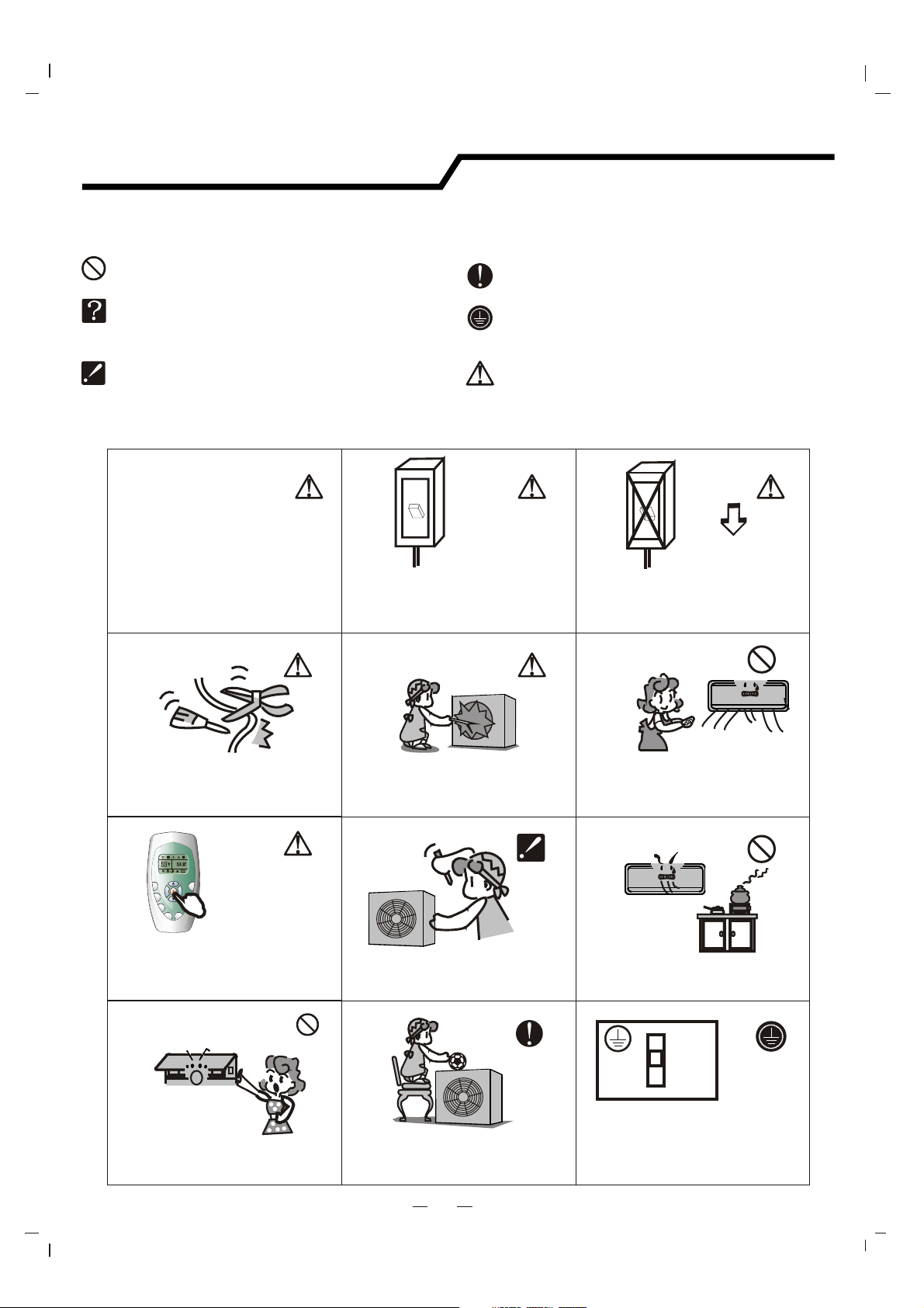
Symbols in this Use and Care Manual are interpreted as shown below.
Do not do.
The feature of the appliance,
instead of a fault.
Pay attention to such a situation.
Use correct power supply in
accordance with the rating plate
requirement. Otherwise, serious
faults or hazard may occur or a
fire maybe break out.
Keep the power supply circuit breaker
or plug from dirt. Connect the power
supply cord to it firmly and correctly,
lest an electric shock or a fire break out
due to insufficient contact.
ON
OFF
Be sure to follow this instruction.
Grounding is essential.
Warning: Incorrect handling could
cause a serious hazard, such as death,
serious injury, etc.
ON
OFF
Do not use the power supply circuit
breaker or pull off the plug to turn it off
during operation. This may cause a fire
due to spark, etc.
Do not knit, pull or press the power supply
cord, lest the power supply cord be broken.
An electric shock or fire is probably caused
by a broken power supply cord.
ON
S
U
T
P
R
E
A
R
M
S
FAN
MODE
TI
M
G
E
RO
N
I
W
N
S
T
I
M
E
EP
R
O
LE
FF
S
CLO
CK
CK
LO
Turn off the appliance by remote control
firstly before cutting off the power supply
if malfunction occurs.
Do not touch the operation buttons
when your hands are wet.
Never insert any obstacle's into the unit.
Since the fan rotates at high speed, this
may cause an injury.
Do not attempt to repair the appliance.
Please call for a qualified service
technician.
Do not place any objects on the outdoor
unit.
3
It is harmful to your health if the cool air
reaches you for a long time. It is advisable
to let the air flow be deflected to all the room.
Prevent the air flow from reaching the gas
burners and stove.
It is the user's responsibility to make the
appliance be grounded according to
local codes or ordinances by a licenced
technician.
Page 5
Identification of parts
O
N
OF
F
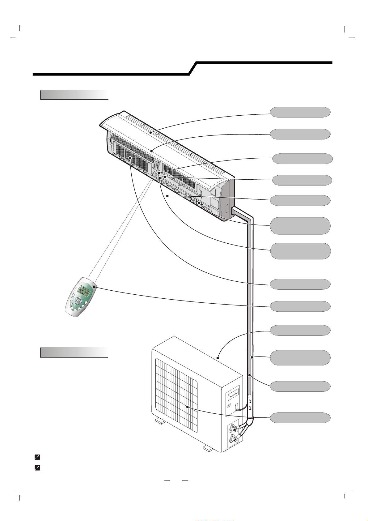
Indoor unit
Air Intake
Front Panel
Display Panel
Emergency Button
Air Outlet
Vertical Adjustment
Louver
O
N
OF
F
S
U
P
E
R
T
I
M
ER
F
AN
O
N
M
O
D
E
T
R
I
ME
A
M
R
S
OF
F
G
N
I
W
S
CL
O
CK
P
E
E
L
S
K
C
O
L
Outdoor unit
Horizontal Adjustment
Louver
Air Filter
T
Remote Controller
Air Intake
Pipes and Power
Connection Cord
Drain Hose
Note: Condensate water drains
at COOLING or DRY operation.
Air Outlet
The figures in this manual are based on the external view of a standard model.
Consequently, the shape may differ from that of the air conditioner you have selected.
The pipes and power connection cords will not be provided. They must be purchased by the customer.
4
Page 6
Identification of parts
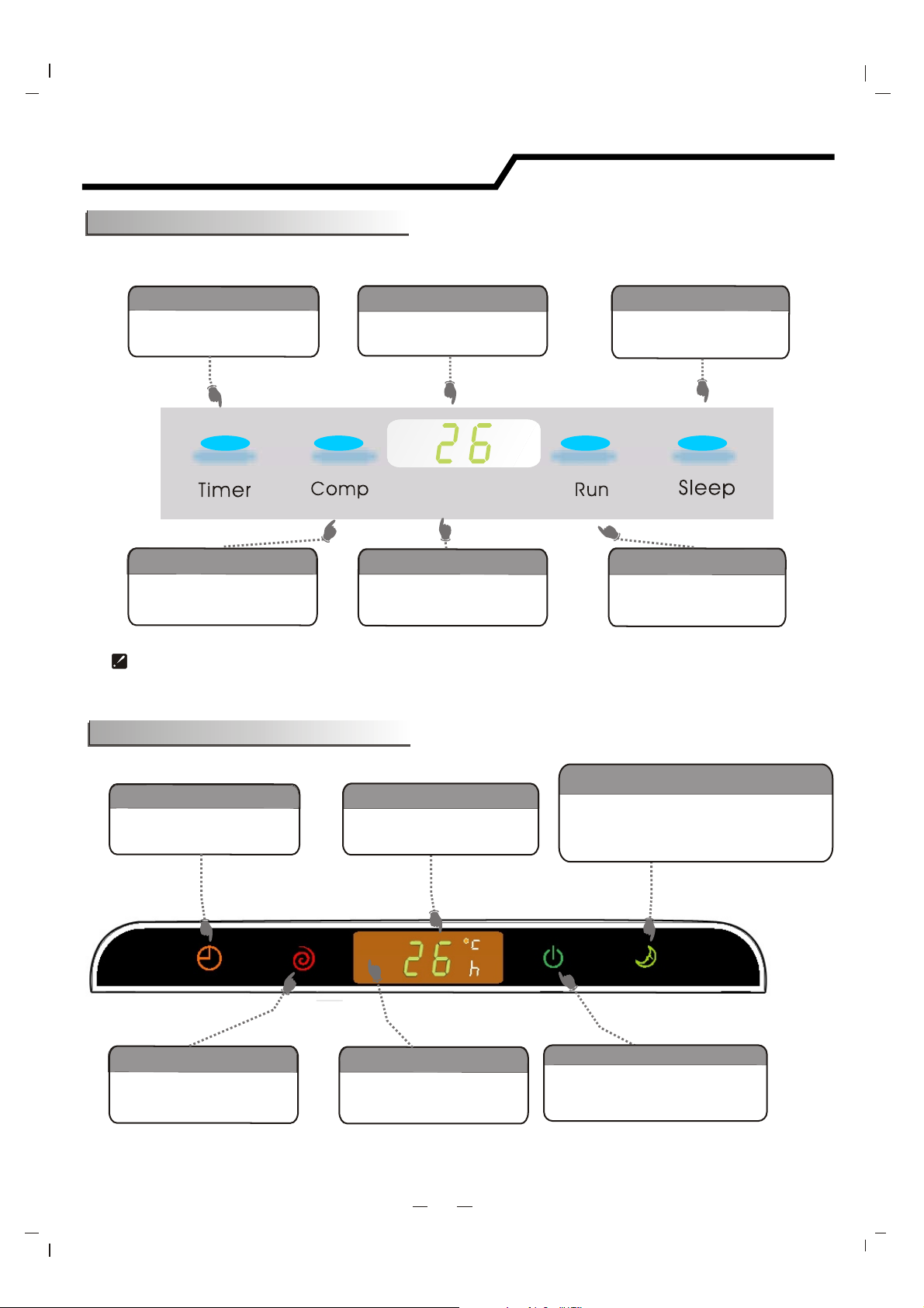
UP series operating and display
Timer Indicator
Lights up during the
set time.
Compressor Indicator
It lights up when
.
compressor is running.
The shape and position of the switches and indicators may vary from different models, but their function are similar.
Temperature Display
Display set temperature.
Signal Receptor
Receive signal from
the remote controller.
Sleep Indicator
Lights up when the
unit is in sleep mode.
Run Indicator
It is on during
operation.
UL series operating and display
Timer Indicator
Lights up during the
set time.
Timer
Timer
Timer
Compressor Indicator
It lights up when
.
compressor is running.
Comp.
Comp.
Temperature display
Display set temperature.
Display trouble symbol..
Signal Receptor
Receive signal from
the remote co
ntroller.
5
Sleep indicator
Lights up when the sleep mode
.
is being set and within
the sleep mode has been set
Run
Run
Run Indicator
Is on during operation and flashes
within 10s after the sleep mode
has been set.
Sleep
Sleep
10s after
.
Page 7
Remote controller
ON
OFF
ON
OFF
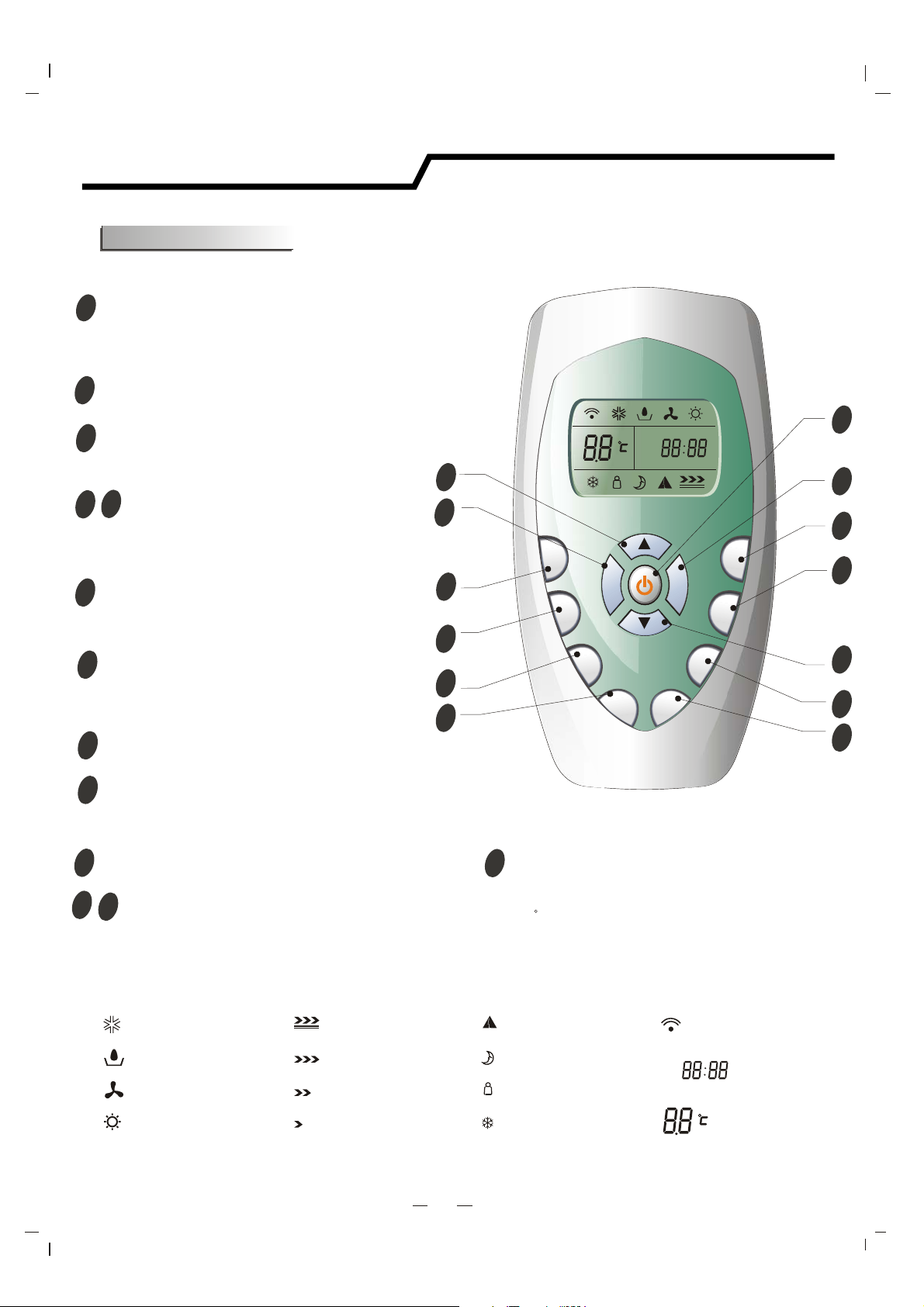
Remote controller
The remote controller transmits signals to the system.
ON/OFF BUTTON
1
The appliance will start turn on when energized or will
turn off when it is in operation, if you press this button.
MODE BUTTON
2
Press this button to select the operation mode.
3
FAN BUTTON
Used to select fan speed in sequence
auto, high, medium or low.
ROOM TEMPERATURE
5
4
SETTING BUTTONS
Used to adjust the room temperature and
the timer, also real time.
6
SMART BUTTON
Used to enter fuzzy logic operation directly,
regardless if the unit is on or off.
SWING BUTTON
7
Used to stop or start vertical adjustment
louver swinging and set the desired up/down
airflow direction.
SLEEP BUTTON
8
Used to set or cancel Sleep Mode operation.
LOCK BUTTON
9
When you press this button, all the buttons
are locked and not available. Press again to
cancel it.
CLOCK BUTTON
10
Used to set the current time.
12
11
TIMER ON/OFF BUTTON
Used to set or cancel the timer operation.
4
3
13
12
11
10
OFF
S
U
P
ER
TI
MER ON
TIMER OFF
13
SUPER BUTTON
FAN
CLOCK
LOC
MODE
K
SMART
ING
SW
EEP
SL
Used to start or stop the fast cooling operation.
(Fast cooling operates at high fan speed with
18 C set temp automatically )
1
2
6
7
5
8
9
Indication symbols on LCD:
Cooling indicator
Dry indicator
Fan only indicator
Heating indicator
Note: Each mode and relevant function will be further specified in following pages.
Auto fan speed Smart indicator
High fan speed
Medium fan speed
Low fan speed
Sleep indicator
Lock indicator
Super indicator
6
Signal transmit.
ON
Display set timer
Display current time
Display set temperature
Page 8
Remote controller
FAN
M
O
D
E
ON
OF
F
O
N
O
FF
FA
N
M
O
D
E
ON
OF
F
Remote controller
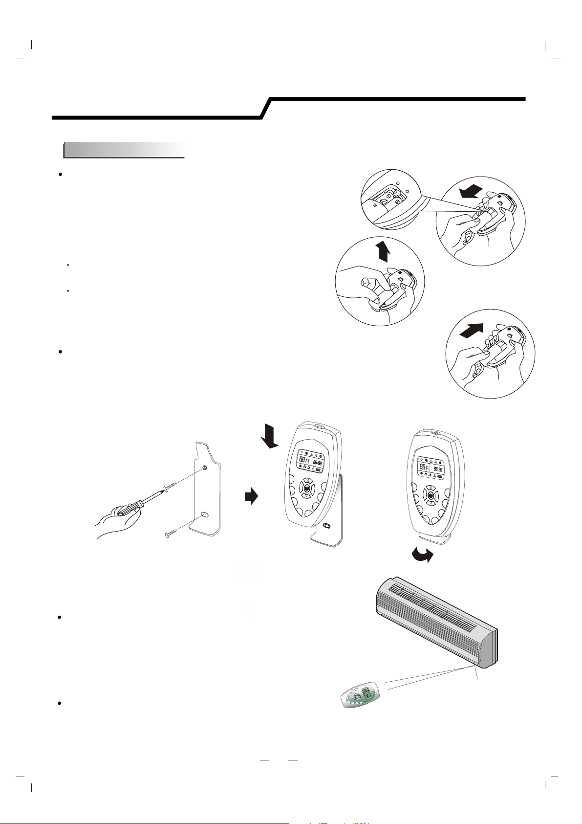
How to Insert the Batteries
Remove the battery cover according to the arrow direction.
Insert new batteries making sure that the (+) and (-) of
battery are matched correctly.
Reattach the cover by sliding it back into position.
Note:
Use 2 LR03 AAA(1.5volt) batteries. Do not use rechargeable batteries.
Replace batteries with new ones of the same type when the display
becomes dim.
If the replacement is done within 1 minute, the remote controller
will keep original presetting. However, if you want to change the
presetting from Heat Pump to Cool Only or Cool Only to Heat Pump,
you should reload batteries 3 minutes after removing the old ones.
(Please refer to page 1 for details.)
Storage and Tips for Using the Remote Controller
The remote controller may be stored mounted on a wall with a holder.
Note: The remote controller holder is an optional part.
How to Use
To operate the room air conditioner, aim
the remote controller to the signal receptor.
The remote controller will operate the air
conditioner at a distance of up to 7m when
pointing at signal receptor of indoor unit.
Choose Cooling Only Remote controller or Heat Pump
SU
P
ER
T
IM
E
R
O
N
O
O
N
T
I
F
M
F
E
F
A
R
N
O
FF
C
L
O
C
K
M
O
D
E
L
O
C
K
S
RT
L
A
M
E
S
E
P
G
N
I
W
S
Signal receptor
Please refer to page 1 " Preparation before use" for details.
7
Page 9
Operation instructions
ON
OFF
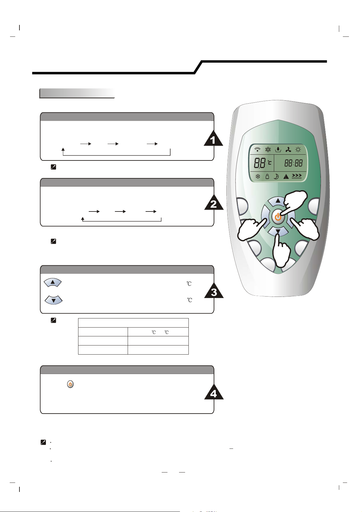
Operation modes
Selecting mode
Each time MODE button is pressed, the operation mode
is changed in sequence:
COOLING
Heating mode is NOT available for cooling only air conditioner.
DRY
FAN ONLY
FAN mode
HEATING
ON
OFF
Each time the "FAN" button is pressed, the fan speed is
changed in sequence:
Auto
At "FAN ONLY" mode, only "High","Medium" and "Low" are available.
At "DRY" mode, Fan speed is set at "Low" automatically, "FAN" button
is ineffective in this case.
High Medium
Low
Setting temperature
Press once to temperature setting by 1raise
Press once to temperature setting by 1lower
Range of available set temperature
*HEATING, COOLING
DRY
ONLY
FAN
*Note: Heating mode is NOT available for cooling only models.
18 ~32
unable to set
unable to set
Turning on
S
UPER
TIM
1
SLEEP
SWING
T
MAR
S
4
FAN
ER
ON
2
TIMER OFF
CLOCK
MODE
3
LOCK
Press button, when the appliance receives the
signal, the RUN indicator of the indoor unit lights up.
SWING, SMART, TIMER ON, TIMER OFF, CLOCK, SLEEP and SUPER operation modes will be
specified in the following pages.
Changing modes during operation, sometimes the unit does not response at once. Wait 3 minutes.
During heating operation, air flow is not discharged at the beginning. After 2 5 minutes, the air flow will be discharged
until temperature of indoor heat exchanger rises.
Wait 3 minutes before restarting the appliance.
8
Page 10

Operation instructions
ON
OFF
Airflow direction control
Airflow direction control
Vertical airflow is automatically adjusted to a certain angle
in accordance with the operation mode after turning on the unit.
Operation mode Direction of airflow
COOLING, DRY
*HEATING,
horizontal
downward
FAN ONLY
*Heating mode is only available for heat pump models.
Vertical airflow control (with the remote controller)
The direction of airflow can be
also adjusted to your own
requirement by pressing the
"SWING" button of the
remote controller.
ON
OFF
S
U
PER
FAN
TIMER O
5
ING
W
S
N
T
I
MER O
FF
CLOCK
SMART
MODE
G
SWIN
EP
SLE
OCK
L
Using the remote controller to set various angles of flow or specific angle
as you like.
Swinging airflow
Pressing "SWING" button once, the vertical adjustment
louver will swing up and down automatically.
Desired direction airflow
Pressing the "SWING" button again when the louvers swing
to a suitable angle as desired.
Horizontal airflow control (with hands)
Turning the control rods of the
horizontal adjustment louvers to
change horizontal air flow as shown.
Note: The shape of the unit may look different
from that of the air conditioner you have selected.
control rods of horizontal
adjustment louvers
Do not turn the vertical adjustment louvers manually, otherwise malfunction may occur. If that happens, turn off the unit
first and cut off the power supply, then restore power supply again.
It is better not to let the vertical adjustment louver tilt downward for a long time at COOLING or DRY mode to prevent
condensed water from dripping.
9
Page 11

Operation instructions
SMART mode
Press the SMART button, the unit enters into SMART mode(fuzzy logic operation) directly regardless if
the unit is on or off. In this mode, temperature and fan speed are automatically set based on the
actual room temperature.
Operation mode and temperature are determined by indoor temperature
Heat pump models
Indoor temperature
21 or below
21 -23
-26
23
Over 26
Operation mode
HEATING
FAN ONLY
DRY
COOLING
Target temperature
22
22
Room temperature
decrease 1.5
operate for 3 minutes
after
26
Cooling only models
Indoor temperature
26
or below
Over 26
SMART button is ineffective in SUPER mode.
Note: Temperature, airflow and direction are controlled automatically in 6th mode.
However, a decrease or rise of up to 2 can be set with the remote controller if you still
feel uncomfortable.
Operation mode
DRY
COOLING
Target temperature
Room temperature
decrease 1.5
operate for 3 minutes
after
26
What you can do in SMART mode
Your feeling
button
adjustment procedure
Uncomfortable
because of
unsuitable air
flow volume.
FAN
Indoor fan speed alternates among
High, Medium and Low each time this
button is pressed.
SUPER
TIM
T
AR
S
LEEP
SM
G
IN
SW
FAN
E
RON
T
IME
ROFF
CLOCK
MODE
OCK
L
Uncomfortable
because of
unsuitable flow
G
IN
SW
Press it once, the vertical adjustment
louver swings to change vertical airflow
direction. Press it again, swings stops.
direction.
CLOCK button
You can adjust the real time by pressing CLOCK button, then
using and buttons to get the correct time, press
CLOCK button again the real time is set.
10
Page 12

Operation instructions
ON
Timer mode
It is convenient to set the timer on with the TIMER ON/OFF buttons when you leave your home
and to achieve a comfortable room temperature at the time you get home. You can also set the
timer off at night to enjoy a good sleep.
How to set TIMER ON
TIMER ON button can be used to set the timer programming as wished in order to
switch on the appliance at your desired time.
i)
Press TIMER ON button, "ON 12:00" flashes on the LCD, then you
can press the or buttons to select your desired time for
appliance on.
Increase
Decrease
Press the button once to increase or decrease the time setting by 1 minute.
Press the button one and a half seconds to increase or decrease the time
or
or
setting by 10 minute.
Press the button for a longer time to increase or decrease the time by 1 hour.
Note: If you don't set the time in 10 seconds after you press TIMER ON button, the remote controller
will exit the TIMER ON mode automatically.
When your desired time displayed on the LCD, press the TIMER ON button and confirm it.
ii)
A "beep" can be heard.
"ON" stops flashing.
The TIMER indicator on the indoor unit lights up.
iiI)
After the set timer displayed for 5 seconds the clock will be displayed on the LCD
or
of the remote controller instead of set timer.
How to cancle TIMER ON
Press the TIMER ON button again, a "beep" can be heard and the indicator disappears,
the TIMER ON mode has been canceled.
Note: It is similar to set TIMER OFF, you can make the appliance switch off automatically at your
desired time.
11
Page 13

Operation instructions
ON
SLEEP mode
SLEEP mode
SLEEP mode can be set in COOLING, HEATING or DRYING operation mode.
This function gives you a more comfortable environment for sleep.
In SLEEP mode,
The appliance will stop operation automatically after operating for 8 hours.
Fan speed is automatically set at low speed.
*Set temperature will rise by 1 if the appliance operates in cooling
mode for 2 hours constantly, then keeps steady.
Set temperature will decrease by 3
heating mode for 3 hours constantly, then keeps steady.
* Note: In cooling mode, if room temperature is 26 or above, set temperature
will not change.
Note: Heating is NOT available for cooling only air conditioner.
at most
at most if the appliance operates in
S
UPE
R
FAN
TIM
ER
O
N
TIMER
OFF
CLO
C
K
MART
S
MODE
WING
S
SLEEP
K
C
LO
SUPER mode
SUPER mode
SUPER mode is used to start or stop fast cooling.
Fast cooling operates at high fan speed, changing the set temperature
automatically to 18 .
SUPER mode can be set when the appliance is in operation or energized.
In SUPER mode, you can set the airflow direction or timer. If you want to
escape from SUPER mode, press any - SUPER , MODE, FAN, ON/OFF
or TEMPERATURE SETTING button, the display will return to the original
mode.
Note:
SLEEP and SMART buttons are not available in SUPER mode.
SUPER button is ineffective in HEATING mode.
The Appliance will continue working in SUPER mode with set temperature of 18
you don't escape from it by pressing any of the buttons mentioned above..
11
, if
S
U
P
E
R
FAN
T
I
ME
R
ON
TIM
E
ROFF
C
L
O
CK
RT
SMA
MODE
ING
W
S
P
E
E
L
S
K
OC
L
11
12
Page 14

Maintenance
Front panel maintenance Air filter maintenance
Cut off the power supply
Turn off the appliance
first before disconnecting
from the power supply.
Please clean the air filter
after using it for about 100 hours.
Clean as follows:
a
Grasp position "a" and
pull outward to remove the
front panel.
Wipe with a soft
and dry cloth.
Use lukewarm water
(below 40 ) to clean
if the appliance
is very dirty.
Never use volatile substance
such as gasoline or polishing
powder to clean the appliance.
Never sprinkle water onto the
indoor unit
Use a dry
soft cloth to
clean it.
Switch off the appliance and remove
the air filter.
a
1.Open the front panel.
2.Press the handle of the filter gently
from the front.
3. Grasp the handle and slide out the filter.
Clean and reinstall the air filter.
If the dirt is conspicuous,
wash it with a solution of
detergent in lukewarm water.
After cleaning, dry well in
shade.
Dangerous!
Electric
shock!
Reinstall and shut the front panel.
Reinstall and shut the front panel by
pressing position front "b" downward.
b
b
Close the front panel in position.
Clean the air filter every two weeks
if the air conditioner operates in an
extremely dusty environment.
13
Page 15

Protection
Operating condition
The protective circuitry device may trip and stop
the appliance in the cases listed below.
Outdoor air temperature is over 24 C
HEATING
Outdoor air temperature is below -7 C
Room temperature is over 27 C
COOLING
Outdoor air temperature is over *43 C
Room temperature is below 21 C
DRY
* For Tropical (T3) Climate condition models, the
temperature point is 52
If the air conditioner runs in COOLING or DRY mode with
door or window opened for a long time when relative
humidity is above 80%,dew may drip down from the outlet.
Room temperature is below 18 C
instead of 43 .
o
o
o
o
o
o
Features of protector
The protective device will work at following cases.
Noise pollution
Install the air conditioner in a place that
can bear its weight to ensure quite
operation.
Install the outdoor unit in a place where
the discharged air and the operation noise
would not annoy your neighbours.
Do not place any obstacles in front of the
air outlet of the outdoor unit to minimise the
noise level.
You need to wait 3 minutes before restarting the unit after stopping operation or changing mode
during operation.
Connect to the power supply and turn on the unit at once, it may start 20 seconds later.
If all operation has stopped, press ON/OFFbutton again to restart, Timer should be set again
if it has been canceled.
Features of HEATING mode
Preheat
At the beginning of HEATING operation, the airflow from the indoor unit is discharged 2-5
minutes later.
Defrost
In HEATING operation the appliance will defrost (de-ice) automatically to raise efficiency.
This procedure usually lasts 2-10 minutes. During defrosting, fans stop operation.
After defrosting completes, it returns to HEATING mode automatically.
Note: Heating is NOT available for cooling only air conditioner models.
14
Page 16

Troubleshooting
The following cases may not always be a malfunction, please check before asking for service.
Trouble Analysis
If the protector trip or fuse is blown.
Does not run
Please wait for 3 minutes and start again,
protector device may be preventing unit to work.
.
If batteries in the remote controller exhausted.
If the plug is not properly plugged.
No cooling or
heating air
Ineffective control
Does not operate
immediately
Peculiar odor
A sound of
flowing water
Is the air filter dirty?
Are the intakes and outlets of the air
conditioner blocked
Is the temperature set properly
If strong interference(from excessive static
electricity discharge, power supply voltage
abnormality)presents, operation will be
abnormal. At this time, disconnect from the
power supply and connect back 3 minutes later.
Changing mode during operation, 3 minutes
will delay.
don't run
This odour may come from another source
such as furniture, cigarette etc, which is
sucked in the outdoor unit and blows out with
the air.
Caused by the flow of refrigerant in the
air conditioner, not a fault.
Defrosting sound in heating mode.
Cracking sound is
heard
Spray mist from
the outlet
The compressor indicator(red) lights on constantly,
and indoor fan stops.
15
The sound may be generated by the expansion
or contraction of the front panel due to change
of temperature.
Mist appears when the room air becomes
very cold because of cool air discharged
from indoor unit during COOLING or DRY
operation mode.
The unit is shifting from heating mode to defrost.
The indicator light will turn off within ten minutes
and returns to heating mode.
Page 17

Installation instructions
Installation diagram
Distance from ceiling
Distance from the wall
should be over 50mm
Distance from floor
should be over 2000mm
should be over 50 mm
Distance from the wall
should be over 50mm
Air intake distance from
the wall should be
over 250mm
air outlet distance from the wall
should be over 500mm
Above figure is only a simple presentation
of the unit, it may not match the external
appearance of the unit you purchased.
Installation must be performed in accordance with
the national wiring standards by authorized personnel only.
16
Air intake distance from the wall
should be over 250mm
over 250mm
Page 18

Installation instructions
Select the best location
Installation of this appliance must be performed by a licensed and qualified installation contractor.
Location for Installing Indoor Unit
Where there is no obstacle near the air outlet and air can be
easily blown to every corner.
Where piping and wall hole can be easily arranged.
Keep the required space from the unit to the ceiling and wall
according to the installation diagram on previous page.
Where the air filter can be easily removed.
Keep the unit and remote controller 1m or more apart from
television, radio etc.
To prevent the effects of a fluorescent lamps, keep as far as
possible.
Do not put anything near the air inlet to obstruct it from air
absorption.
Mount on a solid and structurally strong wall or surface,
which can withstand the weight and will not increase noise
and vibration.
d
Height shoul
Indoor unit
Pipe length is 5
meters or less.
Outdoor unit
an 5m
th
less
be
Outdoor unit
Location for Installing Outdoor Unit
Where it is convenient to install and well ventilated.
Pipe length is 5
meters or less.
Avoid installing it where flammable gas could leak.
Keep the required distance apart from the wall.
Keep the outdoor unit away from fumes, grease and
dirt.
Avoid installing it at the roadside where there is a risk of
muddy water.
A fixed base where is not subject to increasing operation
noise.
t should
Heigh
be less than 5m
Avoid blocking airflows of intake and outlet.
Indoor unit
Important Note:
This air conditioner operates at optimum performance when the connecting pipes between indoor
and outdoor units are 5 meter or less in length. The use of longer tubing will reduce its energy
efficiency, and consequently it is not recommended.
The unit can operate safely, but with higher electricity consumption, with connections of up to 15
meters maximum length. An additional charge of refrigerant of 20 grams per meter in excess of 5
meters of tubing needs to be added to the system. For example, with tubing of 7 meters the
additional charge of refrigerant is:
Additional charge for 7 meter connection = (7 meter- 5 meter) x 20 grams/meter = 40 grams
17
Page 19

Installation instructions
Indoor unit installation
1. Installing the Mounting Plate
Decide an installing location for the mounting plate according to the indoor unit location and piping direction.
. Keep the mounting plate horizontally with a horizontal ruler or dropping line.
Drill holes of 32mm in depth on the wall for fixing the plate.
Insert the plastic plugs to the hole, fix the mounting plate with tapping screws.
Inspect if the mounting plate is well fixed. Then drill a hole for piping.
Hook the line here
holes for fixing
Note: The shape of your mounting plate may be different from the one above, but installation method is similar.
2. Drill a Hole for Piping
Decide the position of hole for piping according to the
location of mounting plate.
Line drops from here
Mounting plate
Dropping line
Indoor
Wall hole sleeve
( hard polythene tube
prepared by user)
Outdoor
Drill a hole on the wall. The hole should tilt a little
downward toward outside.
Install a sleeve through the wall hole to keep the wall
tidy and clean.
5mm
(tilt downward)
3. Indoor Unit Piping Installation
Put the piping (liquid and gas pipe) and cables through the wall hole from outside or put them through
from inside after indoor piping and cables connection complete so as to connect to outdoor unit.
Decide whether saw the unloading piece off in accordance with the piping direction.(as shown below)
Piping direction
trough
Unloading
piece
Saw the unloading piece
off along the trough
1
2
4
3
Note: When installing the pipe at the directions
1,2 or 4, saw the corresponding unloading piece
off the indoor unit base.
After connecting piping as required, install the drain hose. Then connect the power cords. After connecting,
wrap the piping, cords and drain hose together with thermal insulation materials.
18
Page 20

Installation instructions
Piping Joints Thermal Insulation:
Wrap the piping joints with thermal
insulation materials and then wrap
with a vinyl tape.
Thermal insulation
Piping Thermal Insulation:
wrapped with vinyl type
a. Place the drain hose under the piping.
b. Insulation material uses polythene foam over 6mm in thickness.
Note: Drain hose is prepared by user.
Drain pipe should point downward for easy drain flow.
Do not arrange the drain pipe twisted, sticking out or wave
around, do not immerse the end of it in water.
Power cord 1
(for heat-pump)
If an extension drain hose is connected to the drain pipe, make
sure to thermal insulated when passing along the indoor unit.
When the piping is directed to the right, piping, power
Cord and drain pipe should be thermal insulated and
fixed onto the back of the unit with a piping fixer.
large
pipe
drain
small
hose
pipe
Base
Piping fixer
A. Insert the pipe fixer to the slot.
Base
B. Press to hook the pipe fixer onto the base.
Piping fixer
Piping Connection:
a. Connect the indoor unit pipes with two wrenches. Pay special attention
to the allowed torque as shown below to prevent the pipes, connectors
and flare nuts from being deformed and damaged.
b. Pre-tighten them with fingers at first, then use the wrenches.
Large pipe
Power cord
Defrost cable(for heat-pump)
Insert here
drain
hose
Base
Thermal insulation
tube
Drain hose
(prepared by user)
large
pipe
small
pipe
Hook here
Small
pipe
Model
9K, 12K
24K, 30K
9K
12K
24K, 30K
Pipe size
Liquid Side (1/4 inch)
Liquid Side (3/8 inch)
Gas Side (3/8 inch)
Gas Side (1/2 inch)
Gas Side (5/8 inch)
1.8kg.m
3.5kg.m
3.5kg.m
5.5kg.m
7.5kg.m
Torque
Nut width
17mm
22mm
22mm
24mm
27mm
19
Min.thickness
0.6mm
0.6mm
0.6mm
0.6mm
0.6mm
Page 21

Installation instructions
4. Connecting of the Cable
Front panel
Terminal (inside)
Indoor Unit
Connect the power connecting cord to the indoor unit
by connecting the wires to the terminals on the control
board individually in accordance with the outdoor unit
connection.
Note: For some models, it is necessary to remove the cabinet to
connect to the indoor unit terminal.
Indoor unit
Cabinet
Chassis
Outdoor Unit
1). Remove the access door from the unit by loosening
the screw. Connect the wires to the terminals on the
control board individually as the following.
2). Secure the power connecting cord onto the control
board with cable clamp.
Access door
Terminal(inside)
3). Reinstall the access door to the original position
with the screw.
Outdoor unit
The figures in this manual are based on the external
view of a standard model. Consequently, the shape
may differ from that of the air conditioner you have
selected.
Caution:
1. Never fail to have an individual power circuit specifically for the air conditioner. As for the method of
wiring, refer to the circuit diagram posted on the inside of the access door .
2.Comfirm that the cable thickness is as specified in the power source specification.
(See the cable specification table below)
3.Check the wires and make sure that they are all tightly fastened after cable connection.
4. Be sure to install an earth leakage circuit breaker in wet or moist area.
Cable Specifications
Power connecting cord1
(for heat pump)
Typ e
H05RN-F
H05RN-F
Normal cross
- sectional area
0.75mm X2
0.75mm X2
0.75mm X3
2
2
2
Main
power
supply
To indoor
To indoor
To outdoor
Capacity
(Btu/h)
9K, 12K
18K
24K, 30K
Power cord
Typ e
H05VV-F
RVV
Normal cross
- sectional area
1.0~1.5mm X3
1.5~2.0mm X3
2.5mm X3
2
2
2
Power connecting cord
Typ e
H07RN-FH05VV-F
H07RN-F H05RN-F
H07RN-FH07RN-F
Normal cross
- sectional area
1.5mm X3
1.5mm X3
1.5mmX 3(heat pump)
1.5mmX 4(cooling only)
2
2
2
2
Attention:
Accessibility to the plug must be guaranteed even after the installation of the appliance to disconnect
it in case of need. If not possible, connect appliance to a double-pole switching device with contact
separation of at least 3 mm placed in an accessible position even after installation.
2
20
Page 22

Installation instructions
Wiring Diagram
Make sure that the color of wires of the outdoor unit and the terminal No. are the same as those
of the indoor unit.
HASR09A
HASR12A
HEAT PUMP
Indoor unit Indoor unit
Brown
3L 3L
Blue
2L
1L
Power connecting cord I
Brown
Outdoor unit Outdoor unit
Brown
Blue
Brown
2L
1L
1L
HASC09A
HASC12A
COOLING ONLY
Brown
Blue
Brown
Blue
TerminalTerminalTerminalTerminal
1L
NN
NN
Blue
Power connecting cord
Yellow/Green
Yellow/Green
Blue
Power connecting cord
Yellow/Green
Yellow/Green
For above models, the power supply are connected from indoor unit.
HASR24A HASC24A
For these models, the power supply are connected from outdoor unit, with a circuit breaker.
Black)
Power connecting cord
n
Yellow/Gree
COOLING ONLY
Orange(Gray)
Power supply
Y
Blue(B
ello
Brown
w
/Green
lack)
1L
L
N
L
N
Indoor unit
HEAT PUMPHEAT PUMP
Outdoor unit Outdoor unit
Indoor unit
Terminal Terminal Terminal Terminal
Orange(G
3L 3L
Violet(Black)
2L 2L
Black(Brown)
1L 1L
L
N
ray)
Brown
Blue
Yellow/Green
Power connecting cord I
Power connecting cord
Yel lo w/G
Orange(Gray)
Violet(Black)
Black(Brown)
Brown
Blue
re
en
L
N
Terminal
1L
L
N
Orange(Gray)
Brown
Blue(
L
N
Power supply
Defrost Cable (for heat-pump air conditioner only ,and it`s an optional part)
Terminal
Defrost wire (indoor)
After connection, the defrost wire should be well wrapped with a wrapping
tape and the the connector should be put inside the unit.
Ionizer ( ) The ionizer is an optional part
Ionizer wire (indoor)
After connection, the ionizer will be well worked automatically .
21
Defrost wire(outdoor)
Page 23

Installation instructions
Wiring Diagram
Make sure that the color of wires of the outdoor unit and the terminal No. are the same as those
of the indoor unit.
HASR30C HASC30C
Indoor unit
HEAT PUMPHEAT PUMP
Outdoor unit
Terminal Terminal
Orange(Gray)
Violet(Black)
1
L
N
Black(Brown)
Brow
Blue
Green
Yellow/
n
Power connecting cord I
Power connecting cord
Yellow/Green
Orange(Gray)
Violet(Black)
Black(Brow)
Brow
Blue
3L
2L
1L
n
L
N
L
Terminal
Indoor unit
Terminal
1
L
N
Orange(Gray)
Brown
Blue(Black)
Yellow/Green
COOLING ONLY
Power connecting cord
Outdoor unit
Orange(Gray)
Brown
Blue(Black)
Yellow/Green
Terminal
1L
L
N
L
N
N
Power supply
Power supply
For these models, the power supply are connected from outdoor unit, with a circuit breaker.
Power supply
Defrost Cable (for heat-pump air conditioner only ,and it`s an optional part)
Terminal
Defrost wire (indoor)
After connection, the defrost wire should be well wrapped with a wrapping
tape and the the connector should be put inside the unit.
Ionizer ( ) The ionizer is an optional part
Ionizer wire (indoor)
After connection, the ionizer will be well worked automatically .
22
Defrost wire(outdoor)
Page 24

Installation instructions
Outdoor unit installation
1.Install the Drain Port and Drain Hose (for heat-pump model only)
The condensation drains from the outdoor unit when the unit operates
in heating mode. In order not to disturb your neighbours and protect
the environment, install a drain port and a drain hose to direct the
condensation water. Just install the drain port and rubber washer to
the chassis of the outdoor unit, then connect a drain hose to the
port as the right figure shown.
2. Install and Fix Outdoor Unit
Fix with bolts and nuts tightly on a flat and strong floor.
If installed on the wall or roof, make sure to fix the supporter well to prevent it
from shaking.
3. Outdoor Unit Piping Connection
Remove the valve caps from the 2-way and 3-way valve.
Connect the pipes to the 2-way and 3-way valves separately according to the required torque.
4. Outdoor Unit Cable Connection (see previous page)
Drain port
Washer
Drain hose
(prepare by user)
Air purging
Moisture remaining in the refrigeration cycle may cause a malfunction on the
compressor. After connecting the indoor and outdoor units, evacuate air and moisture from refrigerant
cycle using a vacuum pump, as shown below.
Note: To protect the environment, be sure not to discharge the refrigerant to the air directly.
See next page for air purging steps.
Vacuum pump
indoor unit
Service
port
(2) Turn
(8) Tighten
Refrigerant flow direction
3-way valve
(7) Turn to fully open the
valve
Valve cap
(1) Turn
2-way valve
(8) Tighten
(6) Open 1/4 turn
(7) Turn to fully open the valve
valve cap
(1) Turn
(8) Tighten
3-way valve diagram
Connect to outdoor unit
Valve core
connect to indoor unit
open position
service port cap
23
spindle
needle
Page 25

Installation instructions
How to Purge Air Tubes:
(1). Unscrew and remove caps from 2 and 3-way valves.
(2). Unscrew and remove cap from the service valve.
(3). Connect the vacuum pump flexible hose to the service valve.
(4). Start vacuum pump for 10-15 minutes until reaching a vacuum of 10 mm Hg absolutes.
(5). With the vacuum pump still running close the low pressure knob on vacuum pump manifold. Then stop
vacuum pump.
(6). Open the 2-way valve 1/4 turn then close it after 10 seconds. Check tightness of all joints using liquid
soap or an electronic leak detector.
(7). Turn 2 and 3-way valves stem to fully close the valves. Disconnect the vacuum pump flexible hose.
(8). Replace and tighten all valve caps.
Notes
Please read this manual before installing and using it.
Do not let air enter the refrigeration system or discharge refrigerant when moving the air conditioner.
Testing run the air conditioner after finishing installation, and record details of operation.
Type of fuse used on indoor unit controller is 50T, with rating 3.15A,AC250V .
For 9k,12k models type of fuse used on outdoor unit controller is 50T, with rating 20A,AC250V .
For 24k,30k models type of fuse used on outdoor unit controller is 50T, with rating 32A,AC250V .
The fuse for the whole unit is to be provided by the user according to the current at maximum power
Input or use other over-current protective device instead.
Only the air conditioner can be connected to the power line.
The power connection for the air conditioner has to be done at the main power distribution which has
to be of a low impedance.
In order to ensure the suitability of the equipment for connection, the user should consult with the
supply authority, if necessary, that the service current capacity at the interface point is sufficient
for the equipment.
Refer to the rating plate of the equipment for power consumption details.
If the supply cord is damaged, it must be replaced by the manufacturer or its service agent or
similarly qualified person in order to avoid a hazard.
The appliance is initially charged with refrigerant type R22.
If the supply cord is damaged, it must be replaced by the manufacturer, its service agent or
similary qualified persons in order to avoid a hazard.
The air conditioner must be installed by professional engineer.
24
Page 26

Page 27

HISENSE WARRANTY
TERMS AND CONDITIONS
1. HISENSE Australia will provide parts and labour to you the Customer
as set out herein.
2. Nothing in the warranty, limits any rights you may have under the trade
practices act or any other Commonwealth or State Legislation. Such
rights cannot be changed by the conditions in this warranty. Subject to
the conditions below this appliance is warranted by Hisense and/or its
Agents to be free from defects in materials and workmanship for a
period of 60 months from the date of purchase (the “Warranty period”)
3. This warranty: a. covers products purchased as NEW, manufactured for use in
Mainland Australia and Tasmania;
b. is only applicable when installed by a licensed and qualified
installation contractor
c. commences from the date of purchase as listed on the Customers
invoice;
d. provides for the labour and replacement parts necessary to maintain
your product in good operating condition as specified in this warranty
however, if repair is needed because of product failure during normal
usage, Hisense has the option to repair or replace the defective
product or part of the product with a product or part of the product of
like kind and quality and a replacement part may be new or
reconditioned of like kind and quality and may cost less than the
original product purchased and no charges or refunds will be made
based on the replacement product cost difference;
e. applies only to the original purchaser and cannot be transferred;
f. is only applicable when your appliance is used in a domestic
environment;
g. covers products for commercial purposes for a period of 12 months
from the date of purchase.
4. Product Identification
a. Hisense reserves the right to reject claims for any services or work
where the Customer requesting such work or services from Hisense
and/or its agents cannot produce for verification the serial number
and the proof of purchase as per original purchase invoice.
b. The warranty will be voided if any Serial Number sticker provided to
be placed on the equipment is damaged, modified or removed.
c. In the event that a request for repair is made against a warranty
where the Serial Number sticker is not attached to the product or the
customer cannot produce for verification the original invoice, the
repairer will not affect any repairs on the product and the Customer
will be charged a service call-out fee.
5. What is covered by this warranty
a. The equipment is covered for faulty workmanship on parts that have
failed under normal use which are contained within the product.
b. Hisense and/or its Agents will decide if there are any defects in the
material and/or workmanship
c. This warranty is only applicable for repairs on declared equipment
carried out within Mainland Australia and Tasmania
6. What is not Covered by this warranty (excluded):a. Loss or damage occasioned by:
i. Accidental removal of the plug from the power point, failure to
plug in the product to a properly connected power supply or
failure to switch on the power point;
ii. Switching off the power supply or power supply outages;
iii. The introduction of abnormal heat loads to the product;
iv. Failure to observe the operating and installation instructions
supplied with the product; and
b. any damage or failure:
i. of equipment due to the product being inadequately serviced to
manufacturer’s recommendations;
ii. resulting from environmental conditions including and not
limited to dirt, dust, rodents, insects, rust, corrosion, salt builtup, of any part of the product including its parts; or
iii. resulting from excessive use “fair wear and tear”;
iv. resulting from poor installation including and not limited to
positioning and externally fitted equipment such as plumbing
and drainage, cabling, antennae or due to Incompatibility of
connected equipment;
v. to the product caused by overheating as a result of siting or
positioning of the equipment, where there is not provision for
adequate ventilation or a dust free environment;
vi. caused if your appliance has been dismantled, repaired or
serviced by any person other than someone authorised by
Hisense;
vii. to a product or components, caused by power surges or spikes,
including and not limited to, mains power and
telecommunications connections, or to other unspecified
sources, incorrect power current, voltage fluctuation, amperage
fluctuation, rust or corrosion;
viii. due to a dropped product; collision with another object, use
of which is not designed, negligence, accident or deliberate
misuse, theft, abuse, vandalism, flood, fire, earthquake,
electrical storms or any other act of God or any war related
events;
c. costs of attendance and testing where no mechanical or electrical
failure is identified;
d. initial setup and installation of the product;
e. Normal maintenance costs and costs incurred through the
installation of items listed as requiring periodic replacement;
f. products with removed or altered serial numbers;
g. consumables such as but not limited to bulbs/globes, batteries,
remote controls;
h. removal and reinstallation of an internal component not performed
by a factory authorised service centre;
i. cosmetic or structural items;
j. Any failures due to the interference from or to other products
and/or sources;
7. The Warranty Ceases if: a. The product ceases to carry the original manufacturer’s serial
number or is sold at an auction;
b. The product is rented;
c. Damage to the product has occurred as listed in point 6b.
8. Neither Hisense nor its representatives provide loan equipment
under the terms of this warranty.
9. Any unauthorised access to the internal hardware of the product will
void this warranty.
10. Replacement items are “Like for like” and is not “new for old” and
does not indicate in any way that a faulty product will be replaced
with a new part or unit.
11. If you reside outside of the service coverage area of your nearest
authorised service agent, this warranty does not cover the costs of
transportation or travel expenses to and from your home.
12. Hisense accepts no liability for items that are lost, damaged, or
stolen as a result of freight, transport or storage. If you are required
to transport the appliance to an authorised service centre, you must
ensure that it is securely packed and insured.
13. On Public Holidays or other periods when regular business and
wholesale operations are temporarily ceased, repairer availability
and warranty response times may extend beyond the standard
response times due to the availability of repairers and parts.
14. Any repair performed on a product under the warranty where no fault
can be found, or the item is deemed by Hisense, or an authorised
Hisense agent, to be not faulty under this warranty, or the repair or
fault is not covered under the warranty, a No Fault Found fee is
payable by the warranty holder of a minimum of $125 inc GST.
15. Any repairs or services required that are outside of the terms and
conditions of the warranty can be carried out at the request of the
customer or due to site attendance were fault is not covered under
warranty as the product not been installed or setup correctly; a credit
card may be required prior to the commencement of such services.
Page 28

WARRANTY CLAIMS PROCEDURE
Please retain this portion for your records
60 MONTHS IN HOME REPAIR WARRANTY
Hisense Australia will provide its nearest service centre for repairs under warranty. You will need to
ensure that you have already called Hisense Warranty Centre and received a JOB NUMBER.
Before making a claim, please make sure that you understand the terms and conditions of the warranty
x
Check and ensure the installation of all power cables to the power point are secure and power is turned on,
all cables leads and connectors are connected properly and that all switches are turned on and functioning
x Check that there is power at the power point by using a small appliance
x Check that all settings are set according to the instruction manual
x Please keep this certificate in a safe place together with your product receipt. Should you need to make a
claim, the responsibility of proof of ownership of the equipment is on you. If a claim is made that is found
not to be covered under this warranty, or no faulty hardware components are found, you will be charged at
Hisense or Hisense Authorised Service Center's standard service charge plus an administration fee.
PLEASE REFER TO THE TROUBLESHOOTING GUIDE
AT THE END OF THIS MANUAL
Service Procedure
Please have your original invoice, model, and serial number ready. To receive service, you are required to:
x Call 1800 447 367. Service claims may be made between 9:00am and 5:00pm AEST week-
days excluding public holidays where a call representative will log your claim for processing.
x You will be provided a JOB NUMBER
x Normally under 2 hours of logging and receiving your proof of purchase for your claim, an Authorised
Service Agent will contact you to proceed with claim.
WARRANTY REGISTRATION
In order to register your warranty, please fill out and return with a copy of your invoice to:
Congratulations on your purchase, This Document sets out terms
and conditions of your product warranty. Please Keep it with your
proof of purchase information in a safe place for future reference
should you require service to your product.
NAME OF PURCHASER _______________________________________________
ADDRESS __________________________________________________________
___________________________________________________________
CITY ______________________________ STATE _______ POSTCODE ________
PHONE (_____)_____________________
MOBILE (_____)_____________________
FAX (_____)_____________________
Hisense Warranty Registration
PO BOX 2268 Seaford Victoria 3198 Australia
The Undersigned hereby acknowledges receipt of the Hisense
warranty service provided. I have read and understand the
conditions and terms of the warranty in its entirety.
SERIAL NUMBER
____________________________________________________________
STORE PURCHASED FROM
____________________________________________________________
CITY _______________________ STATE _______ POSTCODE ________
INVOICE NO. _______________________________________
MODEL NO. _______________________________________
DATE OF PURCHASE _________/___________/__________
SIGNATURE _________________________________________________
 Loading...