

Page 1

HISENSE
DECLARATION
We,
Hisense International Co., Ltd
Hisense(Guangdong) Air Conditioner Co., Ltd.
( Supplier Name & Factory Name )
Floor 22, Hisense Tower, 17 Donghai xi Road, qingdao, 266071, China
No.8 Ronggang Road, Ronggui, Shunde,Foshan, Guangdong, P.R.China
No. 8 Hisense Road,Advanced Manufacturing Jiangsha Demonstration Park,529085 Jiangmen,
Guangdong, P.R. China
( Supplier Address & Factory Address )
declare under our sole responsibility that the product
AIR CONDITIONER
(Category Name)
GK 07H-S/GC 07H-S
GK 09H-S/GC 09H-S
GK 12H-S/GC 12H-S
GK 18H-S/GC 18H-S
GK 24H-S/GC 24H-S
GK 30H-S/GC 30H-S
(Model Name)
to which this declaration relates is in conformity with the technical requirements of the
following standard(s)
EMC Directive- 2014/30/EU
Low Voltage Directive-2014/35/EU
CE Marking Directive-93/68/EEC
LVD standard
EN 60335-1:2012+A11:2014
EN 60335-2-40:2003
+A11:2004+A12:2005+A1:2006+A2:2009
+A13:2012
EN 62233:2008
EMC standard
EN 55014-1:2006
+A1:2009+A2:2011
EN 55014-2:1997
+A1:2001+A2:2008
EN 61000-3-2:2014
EN 61003-3-3:2013
Page 2
We, hereby further declare that the following products (Product catalog) are exactly the same,
only difference being the art work.
AS-07HR4SYDDJ
AS-09HR4SYDDJ3 GK 09H-S/GC 09H-S
AS-12HR4SVDDJ1 GK 12H-S/GC 12H-S
AS-18HR4SWADJ
AS-24HR4SFADJ
AS-30HR4SQBDJ
Jason Zhang Technical Manager
Name of authorized officer Title of authorized officer
2017-03-12
Date of issue Signature & company seal
GK 07H-S/GC 07H-S
GK 18H-S/GC 18H-S
GK 24H-S/GC 24H-S
GK 30H-S/GC 30H-S
Page 3
1.Safety Coniderrations
IMPORTANT!
Please Read Before Starting
This air conditioning system meets strict safety and operating standards. As the installer or service
person, it is an important part of your job to install or service the system, so it operates safely and
efficiently.
For safe installation and trouble-free operation, you must:
● Carefully read this instruction booklet before beginning.
● Follow each installation or repair step exactly as shown.
● Observe all local, state, and national electrical codes.
● Pay close attention to all warning and caution notices given in this manual.
This symbol refers to a hazard or unsafe practice which can result in severe
personal injury or death.
This symbol refers to a hazard or unsafe practice which can result in personal
injury or product or property damage.
If Necessary, Get Help
These instructions are all you need for most installation sites and maintenance conditions. If you
require help for a special problem, contact our sales/service outlet or your certified dealer for
additional instructions.
In Case of Improper Installation
The manufacturer shall in no way be responsible for improper installation or maintenance service,
including failure to follow the instructions in this document.
SPECIAL PRECAUTIONS
When Wiring
ELECTRICAL SHOCK CAN CAUSE SEVERE PERSONAL INJURY OR DEATH. ONLY A
QUALIFIED, EXPERIENCED ELECTRICIAN SHOULD ATTEMPT TO WIRE THIS SYSTEM.
● Do not supply power to the unit until all wiring and tubing are completed or reconnected and
checked.
● Highly dangerous electrical voltages are used in this system. Carefully refer to the wiring diagram
and these instructions when wiring. Improper connections and inadequate grounding can cause
accidental injury or death.
● Ground the unit following local electrical codes.
● Connect all wiring tightly. Loose wiring may cause overheating at connection points and a possible
Page 4
fire hazard.
When Transporting
Be careful when picking up and moving the indoor and outdoor units. Get a partner to help, and bend
your knees when lifting to reduce strain on your back. Sharp edges or thin aluminum fins on the air
conditioner can cut your fingers.
When Installing
● In a Ceiling or Wall
Make sure the ceiling/wall is strong enough to hold the unit’s weight. It may be necessary to
construct a strong wood or metal frame to provide added support.
● In a Room
Properly insulate any tubing run inside a room to prevent“sweating” that can cause dripping and
water damage to walls and floors.
● In Moist or Uneven Locations
Use a raised concrete pad or concrete blocks to provide a solid, level foundation for the outdoor unit.
This prevents water damage and abnormal vibration.
● In an Area with High Winds
Securely anchor the outdoor unit down with bolts and a metal frame. Provide a suitable air baffle.
● In a Snowy Area (for Heat Pump-type Systems)
Install the outdoor unit on a raised platform that is higher than drifting snow. Provide snow vents.
When Connecting Refrigerant Tubing
△ Use the flare method for connecting tubing.
△ Apply refrigerant lubricant to the matching surfaces of the flare and union tubes before connecting
them, then tighten the nut with a torque wrench for a leak free connection.
△ Check carefully for leaks before starting the test run.
When Servicing
△ Turn the power OFF at the main power box (mains) before opening the unit to check or repair
electrical parts and wiring.
△ Keep your fingers and clothing away from any moving parts.
△ Clean up the site after you finish, remembering to check that no metal scraps or bits of wiring have
been left inside the unit being serviced.
Others
△ Ventilate any enclosed areas when installing or testing the refrigeration system. Escaped
refrigerant gas, on contact with fire or heat, can produce dangerously toxic gas.
△ Confirm upon completing installation that no refrigerant gas is leaking. If escaped gas comes in
contact with a stove, gas water heater, electric room heater or other heat source, it can produce
dangerously toxic gas.
NOTE:
、
The figure
size and parameter of the product may not be identical with the service manual, please
take the actual product as the standard.
Page 5
Degree of protection (IN) / (OUT)
Class of electroprotection (IN) / (OUT)
Horizontal Auto Swing Louver
Optional
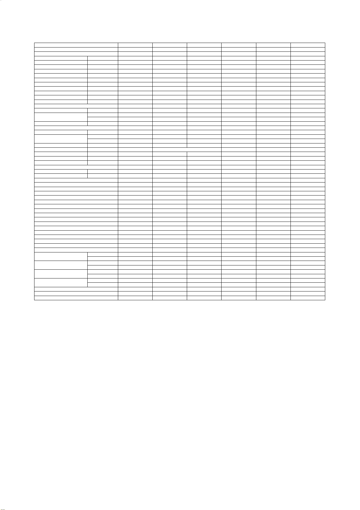
2.Product Specification
Model No.
Type
Ratings
Cooling Capacity
Heating Capacity
Rated Input-Cooling W 655 780 998 1555 2115
Rated Input-Heating W 610 705 885 1440 1965
Moisture Removal L/H.r
Air Circulation (Indoor) m3/h
Air Circulation (Outdoor) m3/h
EER for Cooling W/W
COP for Heating W/W
Energy Class Cooling
Energy Class Heatling
Refrigerant
Refrigerant charge volume g
Indoor Unit Noise Level
Outdoor Unit Noise Level dB (A)
Power Supply
Voltage, Frequency, Phase V 220-240V~,50Hz,1P 220-240V~,50Hz,1P 220-240V~,50Hz,1P 220-240V~,50Hz,1P 220-240V~,50Hz,1P 220-240V~,50Hz,1P
Rated Current
maximal pipe length m
maximal heights' interval m
LRA A
Connecting Pipe Diameter
Liquid Pipe inch
Gas Pipe inch
Features
Display on Front Panel
LCD Wireless Remote Controller
Removable and washable Panel
Washable PP Filter
24 Hours Timer
3 Speed and Auto Indoor Fan Control
Vertical Auto Swing Louver
Sleep Operation
Smart Function
Super Function
Compressor Indicator
Auto Restart
Dimmer
2 Ways Draining Connection (Left or Right)
Other
Net Dimensions
WxHxD (mm)
Net Weight (Kg)
Packing Dimensions WxHxD
(mm)
Gross Weight (Kg)
Loading Capacity (20'/40'/40'HC )
Loading Capacity (20'/40'/40'HC )(with pipe)
Test Standard
W 2100 2500 3200 5000 6800
W 2200 2550 3200 5200 7100
High(dB (A))
Low(dB (A))
Cooling (A)
Heating (A)
(IP)
(I/II)
(
Indoor Unit 745×270×212 745×270×212 745×270×212 915×315×235 915×315×235 1085×315×235
Outdoor Unit 660×482×240 660×482×240 715×240×482 760×545×255 830×629×285 832×702×312
Indoor Unit 8 8 8 12 12.5 15
Outdoor Unit 21.5 23 26 36 45 54.5
Indoor Unit 800×335×265 800×335×265 800×335×265 1000×390×315 1000×390×315 1170×390×315
Outdoor Unit 780×530×315 780×530×315 830×315×530 890×580×350 980×665×385 980×770×420
Indoor Unit 9.5 10 9.5 14 14.5 17.5
Outdoor Unit 23 25 28.5 39 48.5 58.5
AS-07HR4SYDDJ AS-09HR4SYDDJ3 AS-12HR4SVDDJ1 AS-18HR4SWADJ AS-24HR4SFADJ AS-30HR4SQBDJ
T1, H/P, ON/OFF T1, H/P, ON/OFF T1, H/P, ON/OFF T1, H/P, ON/OFF T1, H/P, ON/OFF
0.8 0.9 1.5 1.7 1.8
460 600 500 1050 1050
1600 1600 1800 2500 2600
3.21 3.21 3.21 3.21 3.22
3.61 3.62 3.62 3.61 3.61
A A A A A
A A A A A
R410A R410A R410A R410A R410A
550 530 710 1190 1520
38 38 39 46 46
34 35 34 39 35
53 52 55 58 58
2.9 3.5 4.5 7.0 9.5
2.7 3.2 4 6.5 8.8
IPX0/IPX4 IPX0/IPX4 IPX0/IPX4 IPX0/IPX4 IPX0/IPX4 IPX0/IPX4
CLASS I / CLASS I CLASS I / CLASS I CLASS I / CLASS I CLASS I / CLASS I CLASS I / CLASS I CLASS I / CLASS I
15 15 15 15 15 15
5 5 5 5 5 5
13.3 15 19.2 25.9 43 68
1/4 1/4 1/4 1/4 3/8
3/8 3/8 1/2 1/2 5/8
LED LED LED LED LED LED
Yes Yes Yes Yes Yes
Yes Yes Yes Yes Yes
Yes Yes Yes Yes Yes
Yes Yes Yes Yes Yes
Yes Yes Yes Yes Yes
)
Yes Yes Yes Yes Yes
Yes Yes Yes Yes Yes
Yes Yes Yes Yes Yes
Yes Yes Yes Yes Yes
Yes Yes Yes Yes Yes
Yes Yes Yes Yes Yes
Yes Yes Yes Yes Yes
Yes Yes Yes Yes Yes
Yes Yes Yes Yes Yes
146/308/343 146/308/343 143/299/332 93/202/218 83/170/195 69/134/151
155/326/360 155/326/360 153/315/345 100/212/234 83/170/195 69/134/151
EN 14511 EN 14511 EN 14511 EN 14511 EN 14511 EN 14511
T1, H/P, ON/OFF
8200
8600
2985
2860
2.9
1200
2800
2.75
3.01
D
D
R410A
1830
50
45
60
13.5
12.9
3/8
5/8
Yes
Yes
Yes
Yes
Yes
Yes
Yes
Yes
Yes
Yes
Yes
Yes
Yes
Yes
Page 6
3.Product Drawing
Indoor 7.9.12.18.24K
Indoor 30K
Page 7
Outdoor 7.9.12.18.24K
Outdoor 30K
Page 8
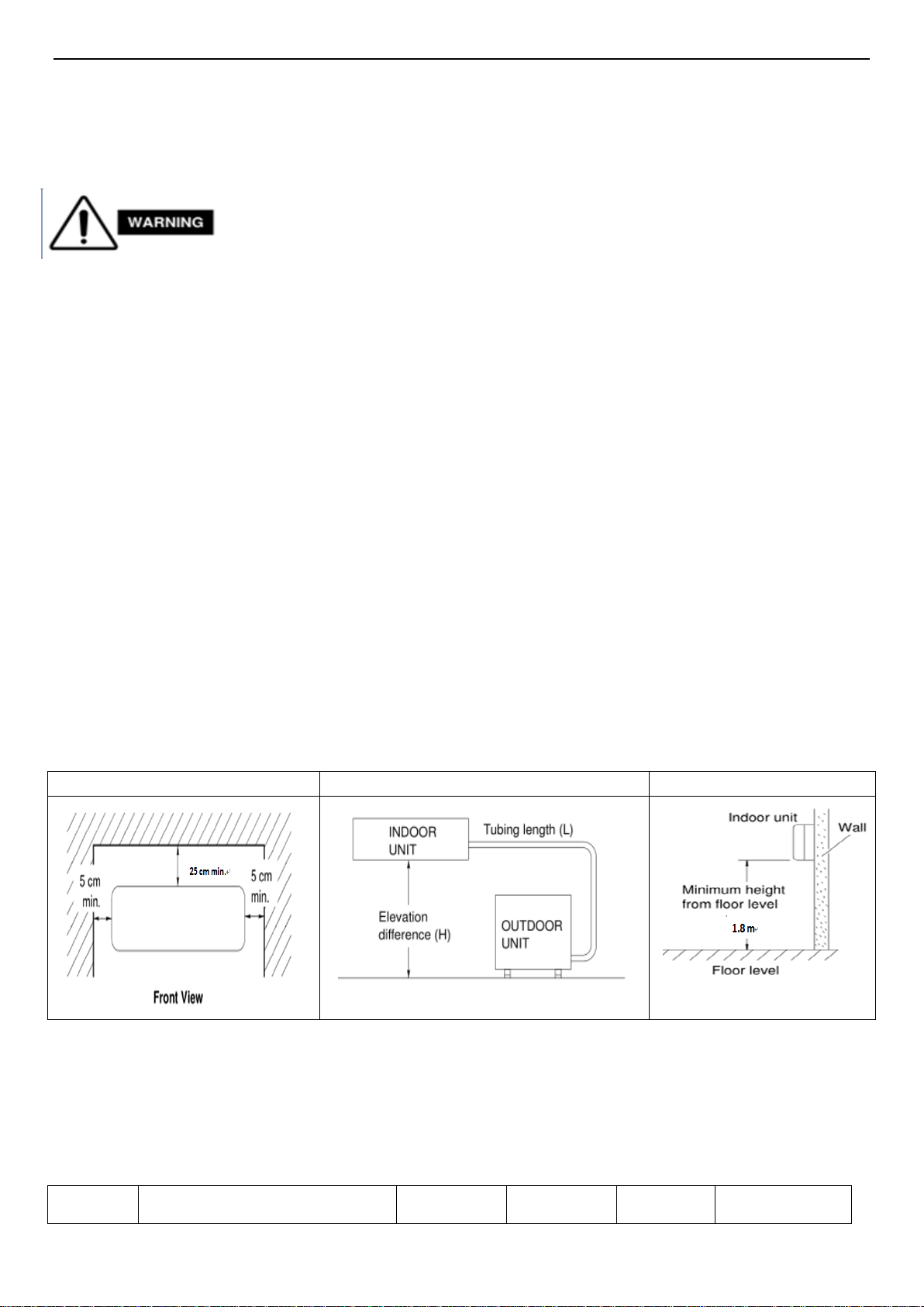
4. Installation Instruction
To prevent abnormal heat generation and the possibility of fire, do not place
obstacles, enclosures and grilles in front of or surrounding the air conditioner in a
way that may clock air flow. And, more than 1 meter away from any antenna or power lines or connecting
wires used for TV, radio, telephone, security system, or intercom. Electrical noise from any of these
sources may affect operation.
4-1. Installation Place and Condition
Indoor unit
Avoid:
△ direct sunlight.
△ nearby heat sources that may affect performance of the unit.
△ areas where leakage of flammable gas may be expected.
△ places where large amounts of oil mist exist.
Do:
△ Select an appropriate position from which every corner of the room can be uniformly cooled.
△ Select a location that will hold the weight of the unit.
△ Select a location where tubing and drain hose have the shortest run to the outside. (See a)
△ Allow room for operation and maintenance as well as unrestricted air flow around the unit. (See b)
△ Install the unit within the maximum elevation difference (H) above or below the outdoor unit and
within a total tubing length (L) from the outdoor unit as detailed (See table 1 and c)
a b c
table 1
Capacity Pipe Size Standard Max. Max. Additional
Page 9
(Btu/h)
5k~14k
18k~28k
30k~38k
* If total tubing length becomes 7.5 to 15 m (max.), charge additional refrigerant as the table1 for
reference. And no additional compressor oil is necessary.
GAS LIQUID
3/8"(Ø9.52) 1/4"(Ø6.35) 7.5 7 15 20
1/2"(Ø12.7) 1/4"(Ø6.35) 7.5 7 15 20
1/2"(Ø12.7) 1/4"(Ø6.35) 7.5 15 30 20
5/8"(Ø15.88) 1/4"(Ø6.35) 7.5 15 30 20
5/8"(Ø15.88) 3/8"(Ø9.52) 7.5 15 30 30
5/8"(Ø15.88) 3/8"(Ø9.52) 7.5 15 30 30
3/4"(Ø19.05) 3/8"(Ø9.52) 7.5 15 30 50
Length
(m)
Elevation
B (m)
Length
A (m)
Refrigerant
(g/m)
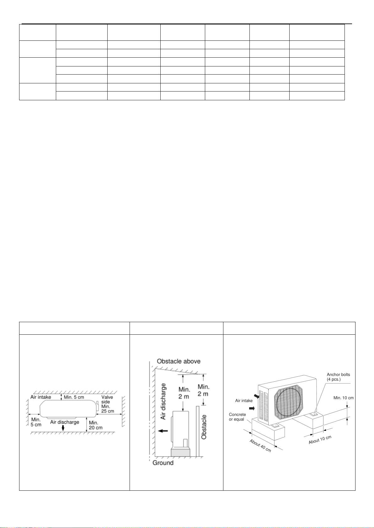
Outdoor unit
Avoid:
△ Heat sources, exhaust fans, etc.
△ Damp, humid or uneven locations.
DO:
△ Choose a place as cool as possible.
△ Choose a place that is well ventilated.
△ Allow enough room around the unit for air intake or exhaust and possible maintenance. (see a1,
b1 & c1)
△ Provide a solid base (level concrete pad, concrete block, 10 × 40 cm beams or equal), a minimum
of 10 cm above ground level to reduce humidity and protect the unit against possible water damage
and decreased service life.
△ Install cushion rubber under unit’s feet to reduce vibration and noise.
△ Use lug bolts or equal to bolt down unit, reducing vibration and noise.
a1 b1 c1
Page 10
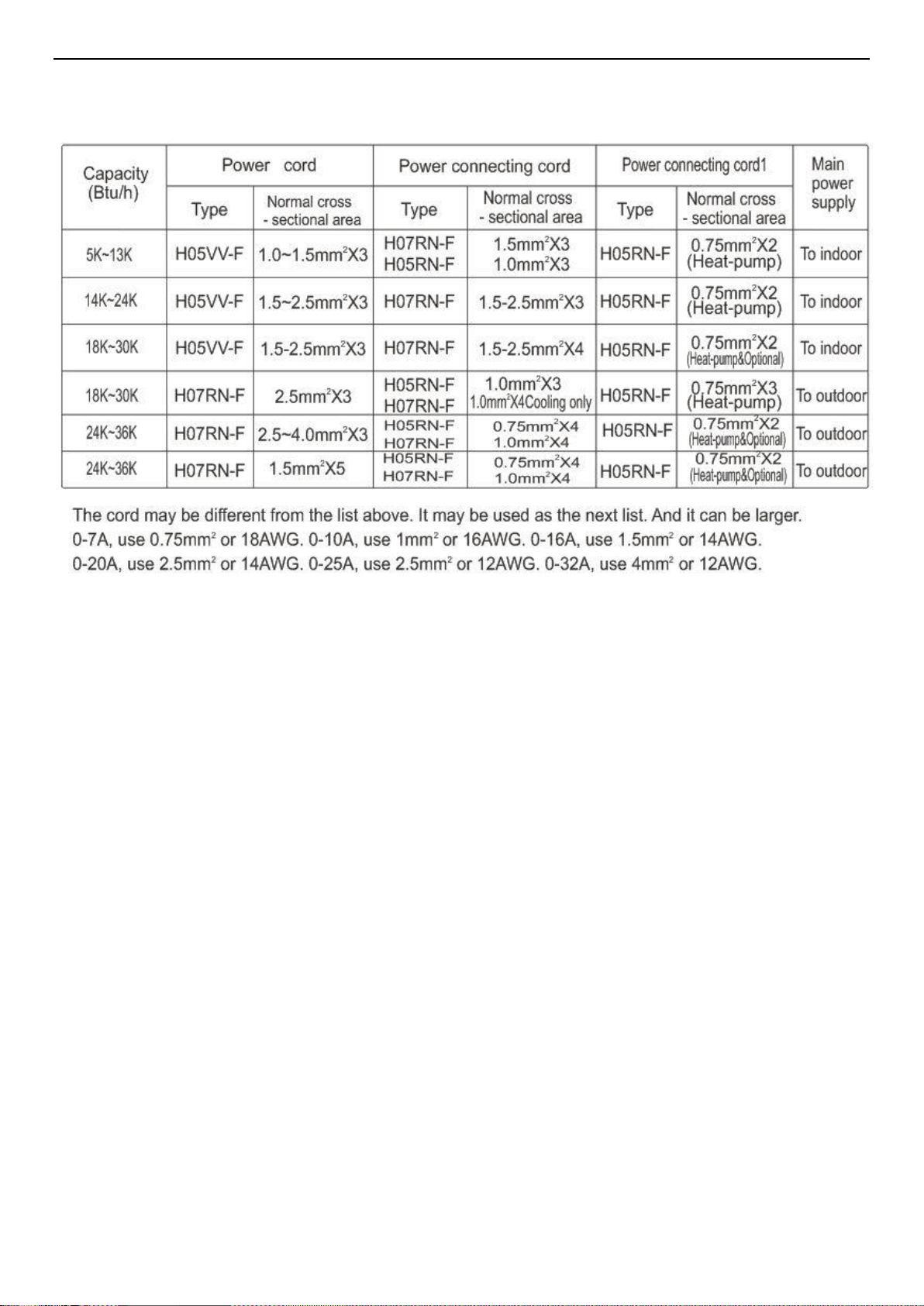
Recommended Wire Diameter:
Page 11
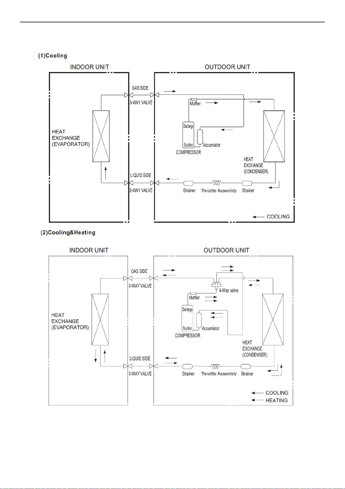
4-1. Refrigerant Flow System
NOTE: In different models, the throttle assembly may be Capillary or Electronic expansion valve.
Page 12
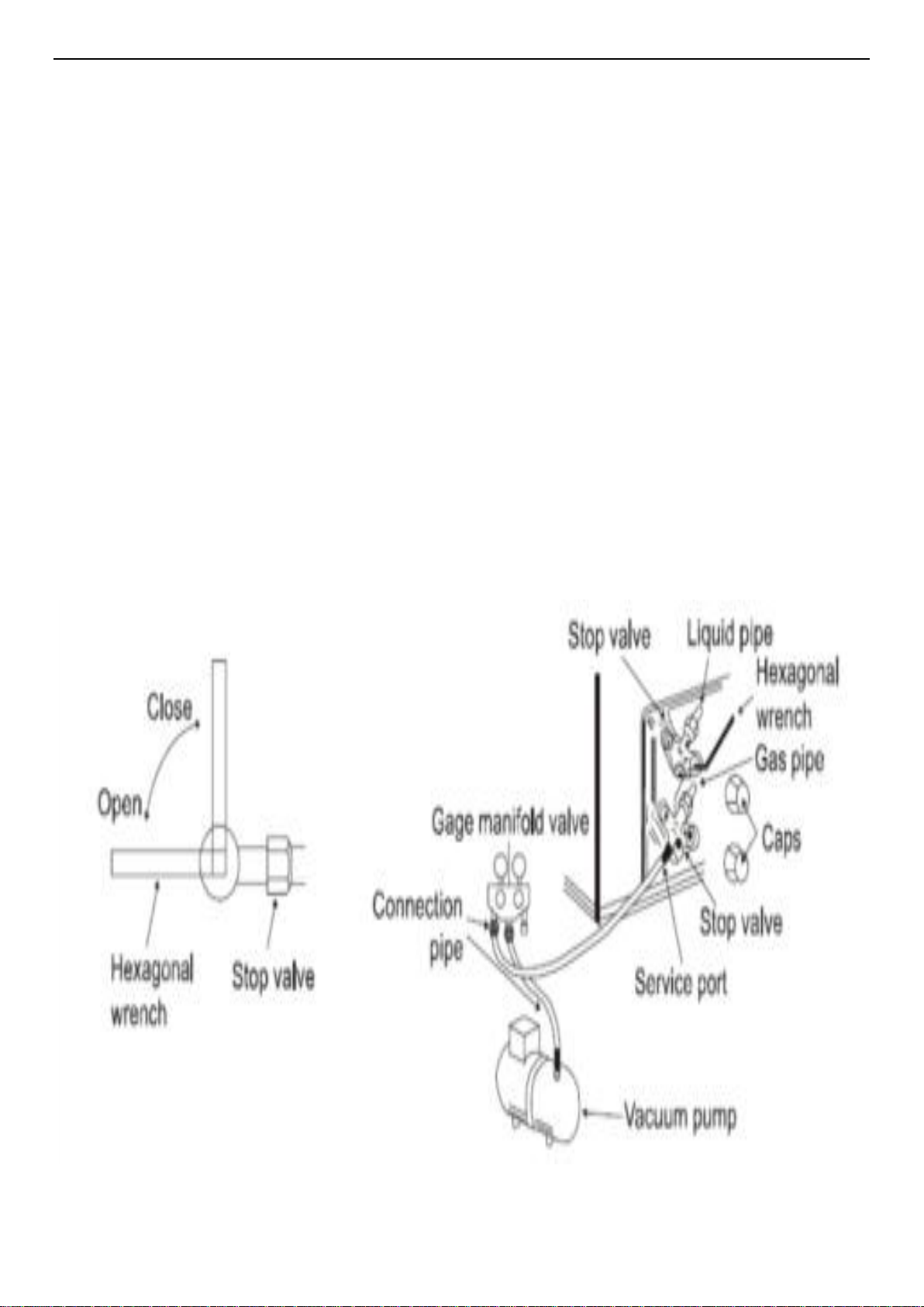
4-2. Air Purging and Leakage Test
1. Connect charging hose of manifold valve to charge end of low pressure valve (both high/low
pressure valves must be tightly shut).
2. Connect joint of charging hose to vacuum pump.
3. Fully open the handle of Lo manifold valve.
4. Open the vacuum pump to evacuate. At the beginning, slightly loosen joint nut of low pressure
valve to check if there is air coming inside. (If noise of vacuum pump has been changed, the reading
of multimeter is 0) Then tighten the nut.
5. Keep evacuating for more than 15mins and make sure the reading of multi-meter is -1.0 X10⁵ pa
(-76cmHg).
6. Check the vacuum with the gage manifold valve, then close the gage manifold valve, and stop the
vacuum pump.
7. Leave it for one or two minutes. Make sure the pointer of the gage manifold valve remains in the
same position.
8. Remove the gage manifold valve quickly from the service port of the stop valve.
After refrigerant pipes are connected and evacuated, fully open all stop valves on gas and liquid pipe
sides.
9. Opening without fully opening lowers the performance and cause dangerous.
10. Tighten the cap to the service port to obtain the initial status.
11. Retighten the cap
12. Leak test
Page 13

4-3. Test Running
△ Check after Installation
Items to be checked Possible malfunction
Has it been fixed firmly? The unit may drop, shake or emit noise.
Have you done the refrigerant leakage test?
Is heat insulation sufficient? It may cause condensation and dripping.
Is water drainage satisfactory? It may cause condensation and dripping.
Is the voltage in accordance with the rated
voltage marked on the nameplate?
Is the electric wiring and piping connection
installed correctly and securely?
Has the unit been connected to a secure earth
connection?
Is the power cord specified?
Are the inlet and outlet openings blocked?
Is the length of connection pipes and
refrigerant capacity been recorded?
It may cause insufficient
cooling(heating)capacity
It may cause electric malfunction or damage the
product.
It may cause electric malfunction or damage the
part.
It may cause electrical leakage.
It may cause electric malfunction or damage the
part.
It may cause insufficient
cooling(heating)capacity.
The refrigerant capacity is not accurate.
△Operation Test
1. Before Operation Test
(1)Do not switch on power before installation is finished completely.
(2)Electric wiring must be connected correctly and securely.
(3)Cut-off valves of the connection pipes should be opened.
(4)All the impurities such as scraps and thrums must be cleared from the unit.
2. Operation Test Method
(1)Switch on power and press “ON/OFF” button on the remote controller to start the operation.
(2)Press MODE button to select the COOL, HEAT (Cooling only unit is not available), FAN to check
whether the operation is normal or not.
Page 14

5. Function Operation
5-1. Operation Range (cooling and heating)
Argentina Model :
Temperature Indoor Air Intake Temp. Outdoor Air Intake Temp
COOLING
HEATING
Mexico Model :
COOLING
HEATING
Maximum 30 43 ℃
Minimum 16℃ 16℃
Maximum 30℃ 24℃
Minimum / -10℃
Temperature Indoor Air Intake Temp. Outdoor Air Intake Temp
Maximum 30
Minimum
Maximum
Minimum /
16℃ 16℃
30℃ 24℃
46 ℃
-10℃
5-2. Remote Controller Operation & Function
△Remote Controller Instruction
Page 15

Page 16

△Function Instruction
1.Major general technical parameters
1-1 Remote receiver distance(front of the air conditioner): 8 m.
1-2 Remote receiver angle: Less than 60 degrees.
1-3 Temperature control accuracy: ±1℃.
1-4 Time error: Less than 1%.、
2. Functions of the controller
2-1 Display panel
I. Control functions of the remote controller (See operating and installation manual)
II. Display of the indoor unit
Information on the screen:
Displaying Scheme:
7-segment tube:Display set temperature or indoor temperature , and display fault code in trouble
indicating. An error code is displayed according to the signal from the indoor CPU. The error code will
Page 17

flash for 5 seconds while displayed.
Running LED:It is on during operation. It is flashing when the unit defrost.
TIMER LED:When the timer mode works, the LED will be lighted.
Sleep LED:When the sleep mode works, the LED will be lighted, and after 10s, the LED will be off.
Compressor LED:It lights up when compressor is running.
Remote control receiver: This section receives signals from the remote control.
3. Control function
3-1 Emergency switch
If the appliance under the Stand-by state, all the Operation Mode, Air volume, Temperature
Setting , Forced Cooling function will be restored as the last time setting when you press on the
“ON/OFF” button, but lost the Air flow direction setting.
If the appliance was connected to the power at first time, it would operate in the auto mode, It
will keep in stand-by state if you press the “ON/OFF” button during the normal operation.
When the appliance under the Stand-by state, press and hold the emergency switch for 5
seconds, the buzzer rings for 1 times, and it will operate in cooling mode, and the indoor fan speed
is set to high-speed, it running has nothing to do with the room temperature.
When press the emergency switch or receive the signal of the remote control, it will exit this
mode, and it will operate with the corresponding order.
3-2 Operator-machine communication
If the unit has I feel function, when the I feel function is set by the remote control, the room
temperature will depend on the remote control and it will be detected by the sensor of the remote
control. Normally the remote control will automatically transmits a signal at an interval of 10
minutes(only for H1 remote control, it is 9 minutes), but if the room temperature changed exceed
1℃ in a short period of time, the remote control will transmits a signal within 2 minutes. If the indoor
unit has not received a remote signal within 30 minutes, the room temperature will depend on the
room temperature sensor of indoor unit.
3-3 Timer function
Real time of Timer setting
(1) The max Timer ranges is 24 hours.
(2) Timer ON/OFF
(3) Timer ON/OFF can be set available in turn.
(4) The Timer accurate more than 97%
(5) The Timer can be adjusted by 1 min increase.
(6) The appliance can be set the ON-Timer and OFF-Timer in the same time, but no any timer
setting indicated.
3-4 Sleep
(1)The Sleep mode can only be set during Cool, Heat and Dry mode.
(2)When the appliance run in the Sleep mode, it will stop after 8 hours operation, then it will
cancel the Sleep setting. When the appliance operate under the OFF-Timer setting condition, if the
Page 18

OFF-Timer setting less than 8 hours, it will keep the Sleep mode till the OFF-Timer setting; if the
OFF-Timer setting more than 8 hours, it will cancel the OFF-Timer setting after the Sleep mode OFF.
(3)When the Sleep mode is select with Cooling mode, if the room temperature not less than
26℃, the setting temperature will not be adjusted, otherwise, the setting temperature will be raised
by 1℃ per hour, but the max setting temperature raise is 1℃.
(4)When the Sleep mode is select with Heat mode, the setting temperature will be decreased
by 1℃ per hour during the successive 3 hour, but the max setting temperature decrease is 3℃.
(5) When the appliance operate with Sleep mode, the indoor fan run in the LOW setting, and
the air flow direction same as the last setting and the temperature and air flow direction can be
adjusted by user. The Running indicator will be flashed 10 times per 1 Hz frequency, then all the
indicators turn OFF except the Sleep light after 5 min elapse. Those indicators will be recovery when
the temperature or Time setting is adjusted, after the setting, the indicators will be lit in 10 sec, then
turn OFF.
3-5 Automatic run (SMART) mode
When the appliance operates at the smart, the air flow direction can be adjusted.
(1) H/C appliance
a. When the setting temperature is 26℃, the appliance will be ran in the Cool if the room
temperature exceeds 26℃.
b. When the room temperature exceeds 23℃, but below 26℃, it will be ran in the Dry mode(It
will turn in Automatic setting After 3 min LOW air volume running.).
c. When the room temperature exceeds 21℃, but below 23℃, it will be operated in the Fan only,
the air volume is set by LOW and the fan speed can be adjusted
d. When the room temperature is not more than 21℃, it will be operated in Heat mode, and the
temperature is set to 22℃.
(2) Cool only appliance
a. When the room temperature exceeds 26℃, it will be ran in Cool mode, and the temperature is
set to 26℃.
b. When the room temperature exceeds 23℃, but not more than 26℃, it will be operated in the
Dry mode.
c. When the room temperature is not more than 23℃, it will be operated in the Fan only, the air
volume is set to LOW and the fan speed can be adjusted
After the appliance start the smart operation, the setting temperature can be adjusted 2℃ or 7℃
(based on the remote mode)(the min accuracy is 1℃) up and down base on the automatic
temperature setting, also the presetting temperature of PCB circuit.
In case of the specific operation selected, it could be re-select the other modes after the
compressor ceased for 5 min or the setting temperature changed.
3-6 Cooling-run mode
3-6-1 Outdoor Fan
The outdoor fan’s speeds except the single speed motor can be changed according to outdoor
ambient temperatures.
When operating at a fixed frequency, the outdoor fan is forced to operate at the high speed.
Page 19

3-6-2 Indoor fan operation
(1)When the indoor fan keep in running condition, this operation state could be controlled by the
remote control with High, Median, Low and Automatic setting.
(2)When the appliance is set Automatic condition in the Cool mode for the first time, the fan
speed will run at Low setting. After that, temperature and fan speed is shown as following.
When the difference between the setting temperature and the room temperature equal to 2℃ or
4℃, the indoor fan speed will keep in current speed.
3-6-3 Air flow direction control
The louver is derived by a step motor, and it swings the horizontal louver automatically. Press
the SWING button to swing or stop the louver.
During the louver swing in normal operation, the current position will be stored. When the
appliance turn off and louver swing automatically to the default position, it will position at the close
position plus 5º.
3-6-4 4-way valve
State: It is interrupted in cooling.
Switchover: When initially powered on for cooling, the 4-way valve is interrupted immediately.
When the heating is changed to the cooling, it needs an interval of 50 seconds for the 4-way valve to
change over from being activated to being interrupted.
3-7 Heating-run mode
3-7-1 Temperature compensation
The temperature compensation is 5º in heating mode. For example, if the set temperature is 25℃
by the remote control, when the room temperature is detected with 31℃, the compressor will turn off.
The main reason is that the hot air is condensed at the top of the house.
Note: The compensation is available only if the room temperature sensor of indoor unit is used
and it is not available when it is subject to the sensor on the remote control.
3-7-2 Indoor fan motor operation
Anti-cold air system:
Page 20

When the appliance run in Heat mode condition, the indoor fan motor operation is shown as
following to prevent the cooling air come out during the appliance operation.
When the appliance turn in the anti-cold air system in the Extra-LOW (Tapped motor set in LOW,
sic passim) during the compressor operation, the louver swang to the Cool air protection position, the
louver recovers to the original position after the air volume change to LOW. When the room
temperature reach to the setting temperature, the compressor will be turn off, and the air flow
change to LOW, the louver swang to the Cool air protective position to prevent the air drop into
human body directly; when the indoor pipe coil temperature drop continuously, it will turn in the
Cooling air protective system in the Extra-LOW or stop the fan motor.
The indoor fan motor is only controlled by the signal of indoor pipe coil temperature, no matter
the compressor turn ON/OFF, even the appliance turn in Heat mode at first time.
The indoor fan motor will operate according to the different setting(High, Median, Low and
Automatic) by the remote control, but the anti-cold air system is prior.
When the appliance run in the Heat mode with the Automatic setting at first time, the fan speed
will be in the LOW setting, and the operation diagram is shown as following
When the difference between the setting temperature and the room temperature equal to 2℃ or
4℃, the indoor fan speed will keep in current speed.
3-7-3 Air flow direction control
The horizontal louver is controlled by a step motor, press the SWING button to swing or stop the
louver.
During the louver run in normal operation, the current position will be stored. When the
appliance turn off and louver swing automatically to the default position, it will position at the default
Page 21

position plus 5º.
4-3-8-4 Outdoor fan
The outdoor fan speeds except single speed motor can be changed according to outdoor ambient
temperatures.
3-7-6 4-way valve
State: It is electrified in heating.
Switchover: When initially powered on for heating, the 4-way valve is activated immediately.
In the change from cooling to heating, it needs an interval of 50 seconds for the 4-way valve to
change over from being interrupted to being activated.
3-8 The super function (option)
In cooling mode, when you press the SUPER button by remote control, the unit will operate for 15
minutes with the following setting:
a. The set temperature is 16℃;
b. The fan speed with highest speed;
c. The compressor runs with high frequency.
3-9 Dehumidifying mode
The dehumidifying mode is illustrated as follows:
Dehumidifying area I: Operation at the frequency in the range (30–60Hz) according to Dt (T
ambient-Tset
).
Dt(℃)
f(Hz)
0 30
indoor
Page 22

0.5 30
1 40
1.5 50
≥2 60
Dehumidifying area II: The compressor stops for 5 minutes and operators for 5 minutes at the lowest
frequency.
Dehumidifying area III: The compressor stops.
3-10 Fan Only Mode Operation
During the appliance run in this mode, the compressor and outdoor fan stop, the indoor fan
operate under the pre-setting of air volume, and the louver swing, and the indoor fan speed same as
the Heating Mode.
5-3. Special Function Fnstruction
Conditions of anti-freezing prohibition of frequency rising:
Condition 1: in the case of anti-freezing frequency decreasing, the temperature of indoor heat exchanger rises to
“anti-freezing frequency decreasing temperature”.
Condition 2: in normal operation, the temperature of indoor heat exchanger reaches “anti-freezing prohibition of
frequency rising temperature”.
Either of the above two conditions is met, the product will enter anti-freezing prohibition of frequency rising state.
Anti-freezing prohibition of frequency rising operation: the compressor is kept at the current frequency, which may
decrease according to situations while cannot rise. The outdoor fan runs.
Condition for the end of anti-freezing prohibition of frequency rising state: when the temperature of indoor heat
exchanger rises to “anti-freezing releasing temperature”, the state of anti-freezing prohibition of frequency rising
is released.
Conditions for defrosting:
A: When the heating compressor consecutively runs for 40 minutes (EEPROM setting value at the current
operating mode);
B:If the ambient temperature minus the temperature of coiled pipe is equal to or higher than six degrees
centigrade (EEPROM setting value in the current operating mode);
C:If the temperature of coiled pipe is equal to or lower than minus two degrees centigrade (EEPROM setting
value in the current operating mode);
If the above three conditions are met simultaneously, defrosting begins.
Defrosting actions:
The compressor stops, and the outdoor fan stops after delay of 30 seconds; in 50 seconds the four-way
valve is power off; and in 10 seconds the compressor starts and runs at “defrosting frequency”.
Conditions for ending defrosting:
Defrosting is over if either of the below conditions is met.
Page 23

A:The accumulated time of defrosting is longer than 12 minutes (EEPROM setting value in the current
operating mode);
B:If the temperature of coiled pipe is equal to or higher than 14 degrees centigrade (EEPROM setting value
in the current operating mode);
Actions of exiting the defrosting state:
The compressor stops, and 50 seconds later the four-way valve opens, and another 10 seconds later the
compressor and outdoor fan restart and begin normal operation.
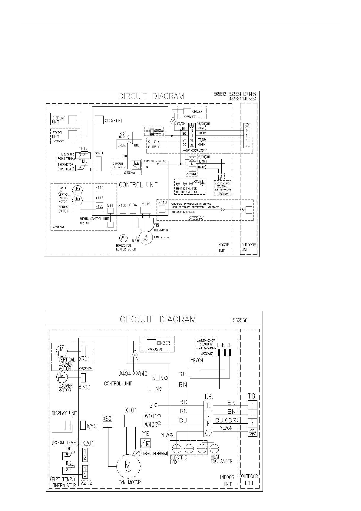
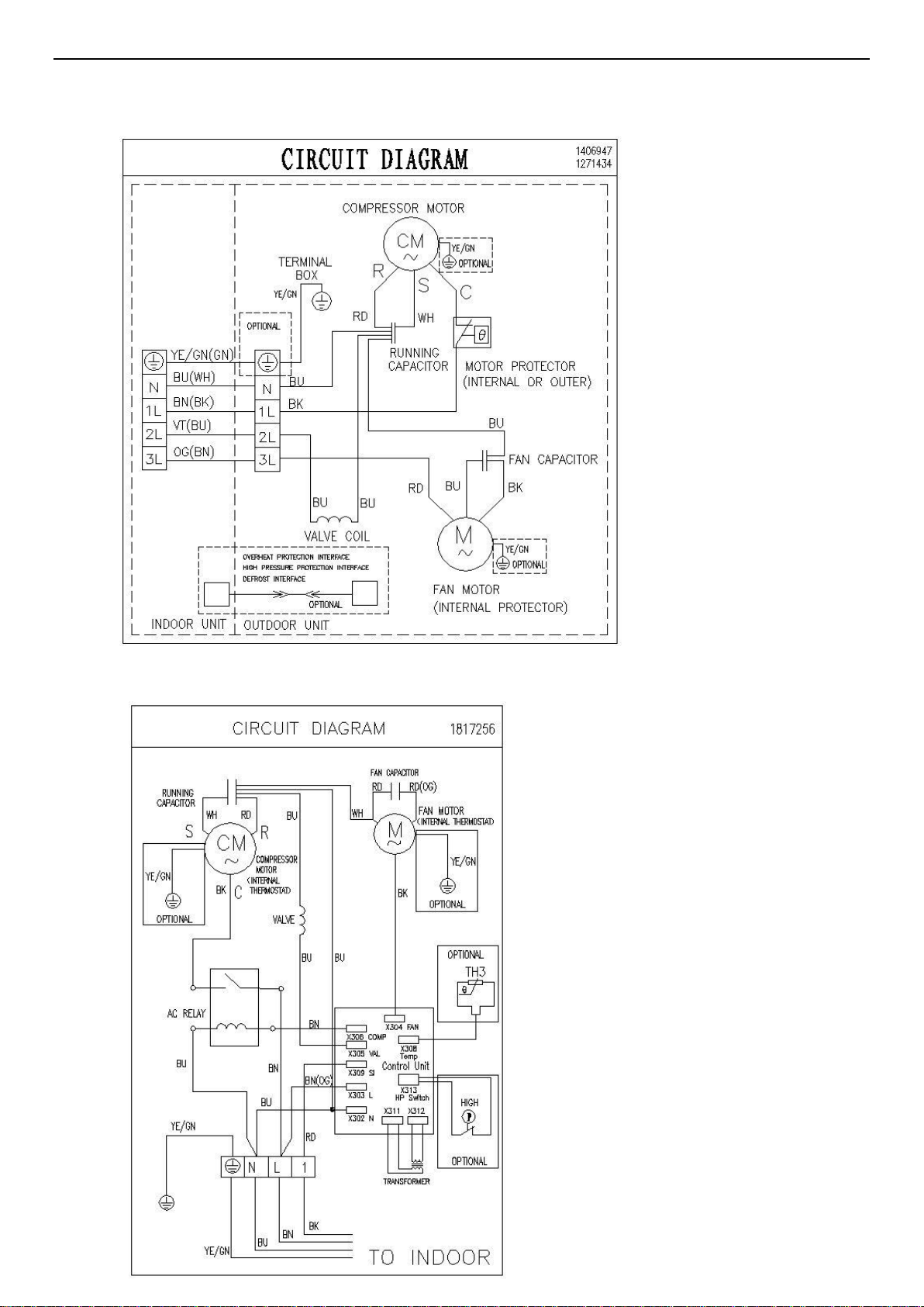
6. Electrical Characteristics
1、FM:FAN MOTOR POWER WIRES
2、FMF:FAN MOTOR FEEDBACK
3、FMC:FAN CAPACITOR
4、SEN:PIPE&ROOM TEMPERATURE SENSOR
5、SM:SWING MOTOR
6、OF:OUTDOOR FAN
7、VAL:VALVE
8、CP:COMPRESSOR
9、L:POWER L
10、N:POWER N
11、ON/OFF:EMERGENCY BOTTON
12、SI:SIGNAL
13、HP:HIGH PERSSURE SWITCH
14、TRS:TRANSFORMER
Page 24

Indoor 7.9.12.18.24K
Indoor 30K
Page 25

6-2. Fan Motor
Drawings attached:
INDOOR AC FAN
OUTDOOR AC FAN
Test in resistance.
TOOL: Multimeter.
Test the resistance of the main winding. The indoor fan motor is fault if the resistance of
main winding 0(short circuit)or∞(open circuit).
Test in voltage
TOOL: Multimeter.
Insert screwdriver into to rotate indoor fan motor slowly for 1 revolution or over, and measure
voltage “YELLOW” and “GND” on motor. The voltage repeat 0V DC and 5V DC.
Notes:
1) Please don’t hold motor by lead wires.
2) Please don’t plug IN/OUT the motor connecter while power ON.
3) Please don’t drop hurl or dump motor against hard material. Malfunction may not be observed at
early stage after such shock. But it may be found later, this type of mishandling void our
warranty.
59
Page 26

Indoor DC Fan Motor
Outdoor DC Fan Motor
6-3. Temperature Sensor
Parameter table attached:
THE PARAMETER OF THE INDOOR COIL AND INDOOR ROOM SENSOR
(R(0)=15k B(0/100)=3450)
Model:AS-30HR4SQBDJ
Page 27

Temperature(℃) Resistance(k) Voltage(V) Temperature(℃) Resistance(k) Voltage(V)
-20 38.757 0.58143512 31 4.292 2.715076661
-19 36.844 0.60795346 32 4.137 2.76063657
-18 35.038 0.63530819 33 3.989 2.805589174
-17 33.331 0.66352684 34 3.847 2.850117358
-16 31.719 0.69257720 35 3.711 2.894109636
-15 30.196 0.72246147 36 3.58 2.937788018
-14 28.755 0.75321223 37 3.455 2.980713033
-13 27.392 0.78480857 38 3.335 3.023117961
-12 26.103 0.81722911 39 3.219 3.065272268
-11 24.882 0.85051031 40 3.108 3.106725146
-10 23.727 0.88458737 41 3.001 3.147759536
-9 22.632 0.91951536 42 2.899 3.187898487
-8 21.594 0.95527085 43 2.801 3.227439565
-7 20.611 0.99179340 44 2.706 3.266717909
-6 19.678 1.02913875 45 2.615 3.305249514
-5 18.794 1.06721353 46 2.528 3.342947037
-4 17.954 1.10609872 47 2.444 3.380169671
-3 17.158 1.14565549 48 2.363 3.416856492
-2 16.401 1.18599135 49 2.286 3.45247766
-1 15.683 1.22696435 50 2.211 3.487894953
0 15 1.26865672 51 2.139 3.522585993
1 14.351 1.31098658 52 2.07 3.556485356
2 13.734 1.35393437 53 2.003 3.590032381
3 13.148 1.39741342 54 1.939 3.622673675
4 12.589 1.44157386 55 1.877 3.654865988
5 12.058 1.48618720 56 1.818 3.686036427
6 11.553 1.53125563 57 1.76 3.717201166
7 11.071 1.57689691 58 1.705 3.747244673
8 10.613 1.62286005 59 1.652 3.776658768
9 10.176 1.66928515 60 1.6 3.805970149
10 9.76 1.71601615 61 1.551 3.834009923
11 9.363 1.76311968 62 1.503 3.861880963
12 8.985 1.81043663 63 1.457 3.888973616
13 8.624 1.85805887 64 1.413 3.91524643
14 8.279 1.90597205 65 1.37 3.941267388
15 7.951 1.95387327 66 1.328 3.967019291
16 7.637 2.00204130 67 1.289 3.991234935
17 7.337 2.05033368 68 1.25 4.015748031
18 7.051 2.09859271 69 1.213 4.039284017
19 6.778 2.14682606 70 1.177 4.062450215
20 6.516 2.19524793 71 1.142 4.085229093
21 6.267 2.24333597 72 1.109 4.106941536
22 6.028 2.29151689 73 1.076 4.12888601
Page 28

23 5.8 2.33944954 74 1.045 4.149715216
24 5.581 2.38741691 75 1.015 4.17007359
25 5.372 2.43506494 76 0.986 4.189944134
26 5.172 2.48247664 77 0.957 4.210004953
27 4.981 2.52951096 78 0.93 4.228855721
28 4.797 2.57653834 79 0.904 4.247168554
29 4.622 2.62291710 80 0.878 4.265640683
30 4.453 2.66931854
Note: the AD value in the table is calculated on the basis of the pull-down resistor is 5.1K.
Page 29

(R(25)=15k B(25/50)=3950)
Model:7.9.12.18.24
Temperature(℃) Resistance(k) Voltage(V)
-20 152.5 4.5522388 E8
-19 143.9 4.528005 E7
-18 135.8 4.5026525 E6
-17 128.3 4.4766225 E4
-16 121.1 4.4489346 E3
-15 114.5 4.4208494 E1
-14 108.2 4.3912338 E0
-13 102.3 4.3606138 DE
-12 96.73 4.3287389 DD
-11 91.51 4.2958408 DB
-10 86 4.2574257 D9
-9 81.97 4.2265649 D8
-8 77.62 4.1902397 D6
-7 73.52 4.1527338 D4
-6 69.05 4.107674 D1
-5 66.01 4.0741884 D0
-4 62.58 4.033256 CE
-3 58.34 3.9773657 CB
-2 56.29 3.947959 C9
-1 53.41 3.9036691 C7
0 50.69 3.8582737 C5
1 48.12 3.8117871 C2
2 45.7 3.7644152 C0
3 43.41 3.7159733 BE
4 41.25 3.6666667 BB
5 39.2 3.6162362 B8
6 37.27 3.5651425 B6
7 35.44 3.5130849 B3
8 33.71 3.4602751 B0
9 32.08 3.4069669 AE
10 30.63 3.3563445 AB
11 29.06 3.2977758 A8
12 27.68 3.2427366 A5
13 26.36 3.1866538 A3
14 25.12 3.1306082 A0
15 23.84 3.069001 9D
16 22.82 3.0169223 9A
17 21.76 2.9597388 97
18 20.75 2.9020979 94
19 19.79 2.8442081 91
20 18.88 2.7863046 8E
21 18.03 2.729337 8B
22 17.21 2.6715306 88
23 16.44 2.6145038 85
24 15.7 2.5570033 82
A/D
Temperature(℃) Resistance(k) Voltage(V)
30 11.99 2.221193 71
31 11.47 2.1666037 6E
32 10.98 2.113164 6C
33 10.51 2.0599765 69
34 10.06 2.0071828 66
35 9.634 1.9554275 64
36 9.229 1.9045359 61
37 8.842 1.8542907 5F
38 8.474 1.8049757 5C
39 8.123 1.7564762 5A
40 7.789 1.7089385 57
41 7.47 1.6622163 55
42 7.165 1.6162869 52
43 6.875 1.5714286 50
44 6.597 1.5272955 4E
45 6.333 1.4843201 4C
46 6.08 1.4421252 4A
47 5.838 1.4008062 47
48 5.608 1.3606366 45
49 5.387 1.3211851 43
50 5.177 1.2828964 41
51 4.976 1.2454946 40
52 4.783 1.2088662 3E
53 4.599 1.1732741 3C
54 4.423 1.1385986 3A
55 4.255 1.1049078 38
56 4.093 1.0718588 37
57 3.939 1.0399176 35
58 3.792 1.00894 33
59 3.65 0.9785523 32
60 3.515 0.9492304 30
61 3.385 0.9205874 2F
62 3.261 0.8928865 2E
63 3.142 0.8659464 2C
64 3.028 0.8398047 2B
65 2.918 0.814265 2A
66 2.813 0.7895919 28
67 2.713 0.7658217 27
68 2.618 0.7429901 26
69 2.524 0.7201552 25
70 2.436 0.6985547 24
71 2.36 0.6797235 23
72 2.268 0.656706 21
73 2.189 0.6367444 20
74 2.114 0.617623 1F
A/D
Page 30

25 15 2.5 80
26 14.33 2.4428912 7D
27 13.7 2.3867596 7A
28 13.1 2.3309609 77
29 12.53 2.2756992 74
75 2.041 0.5988498 1F
76 1.971 0.5806965 1E
77 1.905 0.5634428 1D
78 1.84 0.5463183 1C
79 1.778 0.5298605 1B
80 1.719 0.5140858 1A
Page 31

7.Trouble Shooting
7-1. Error Code Table
7.1 The LED of indoor display board will show the error sequence automatically when the unit has the
Error
code
E2
E4
EA
7.2.The Error inquiry should be operate in the stand-by state, keep 5 sec press and hold on the
displayed, otherwise only the LED of the display board can show.
Error
code
Remark:★Light o Flash x OFF
Content Remark The root cause is may be one of the following
a. It is normally for protection, When
the indoor pipe temperature between 53℃<T<63℃, the outdoor
When the evaporator pipe
temperature is higher
than 63 ℃, the error code
will display
When the indoor fan
speed is lower than 200
rpm, the error code will
display
the error code will display
when the communication
between display board
and control board have in
trouble
fan motor will stop running. When the indoor coil temperature is
higher than 63℃, the error code will display. After the indoor pipe
temperature is lower than 49℃, the air conditioner will restart
normally.
b. The indoor coil temperature sensor is loose;
c. The indoor coil temperature sensor is failure;
d. The indoor control board is failure.
a. There are something block
the indoor fan motor;
b. The fan motor cord connect loose; c.
The fan motor is failure;
d. The indoor control board is failure
a. The connection between the
display board and control board is loose;
b. The indoor control board is failure.
c.The wiring of the display board is failure.
in the indoor unit, the LEDof indoor display board will be shown in 10 sec, then the indoor
h error sequence will be
ly. If the appliance could save information under no power condition, then LED can be
-by state after power resume.
NOTE: If the troubleshooting inquiry display by 7-segment tube, then the error code will be
Remark:★Light o Flash x OFF
Content Remark The root cause is may be one of the following
1
20
The failure for
temperature sensor of
outdoor coil
The failure for outdoor DC
motor
Heat pump
a. The outdoor temperature sensor loose;
b. The outdoor temperature sensor is failure;
c. The indoor control board is failure
a. The motor cord connection loose
b. The motor is invalid
c. The outdoor fan is blocked
d. The outdoor control board is invalid
Page 32

There are something block the indoor fan motor;
High or Low pressure
27
33
34
36
38 Indoor EEPROM failure
39
protection for outdoor
uint
The failure for
temperature sensor of
indoor room
The failure for
temperature sensor of
indoor coil temperature
The failure for
communication of indoor
and outdoor uints
Indoor fan motor run
abnormally
a. The pressure switch is working
b. The pressure switch is invalid
c. The outdoor control board is invalid
a. The indoor room temperature sensor loose;
b. The indoor room temperature sensor is failure;
c. The indoor control board is failure.
a. The indoor coil temperature sensor loose;
b. The indoor coil temperature sensor is failure;
c. The indoor control board is failure.
a. The interconnection cord loose
b. The interconnection cord is not in proper order
c. The indoor control board is invalid
d. The outdoor control board is invalid
a. The EEPROM chip loose;
b. The indoor control board is failure
a.
b. The fan motor cord connect loose; c.
The fan motor is failure; d. The indoor control
board is failure
41
42 Overcooling protection
43 Overheating protection
The failure for Indoor
grounding protective
The indoor control board is failure
a. It is normally for protection,When the
indoor pipe temperature below T<-1℃(-7℃).Outdoor fan motor and
compressor will stop running. When the Indoor pipe temperature is
higher than -1(-7℃),the unit will restart normally
b. The indoor coil temperature sensor is loose;
c. The indoor coil temperature sensor is failure;
d. The indoor control board is failure.
a. It is normally for protection, When the
indoor pipe temperature between 53℃<T<63℃, the outdoor fan
motor will stop running. When the indoor coil temperature is higher
than 63℃, the error code will display. After the indoor pipe
temperature is lower than 49℃, the air conditioner will restart
normally.
b. The indoor coil temperature sensor is loose;
c. The indoor coil temperature sensor is failure;
d. The indoor control board is failure.
Remark:
The failure is detected when the room temperature sensor broken or shorted over 5 sec.
The failure is detected when the temperature sensor of heater exchange broken orshorted over 5 sec.
The failure is detected when each setting data is not match after the EEPPOM self-check twotimes.
The failure is occur when the grounding signal is not detected after the appliance power ON.
Page 33

Page 34

Page 35

Page 36

Page 37

Page 38

 Loading...