

Automation and Network Solutions
Measuring Highlights
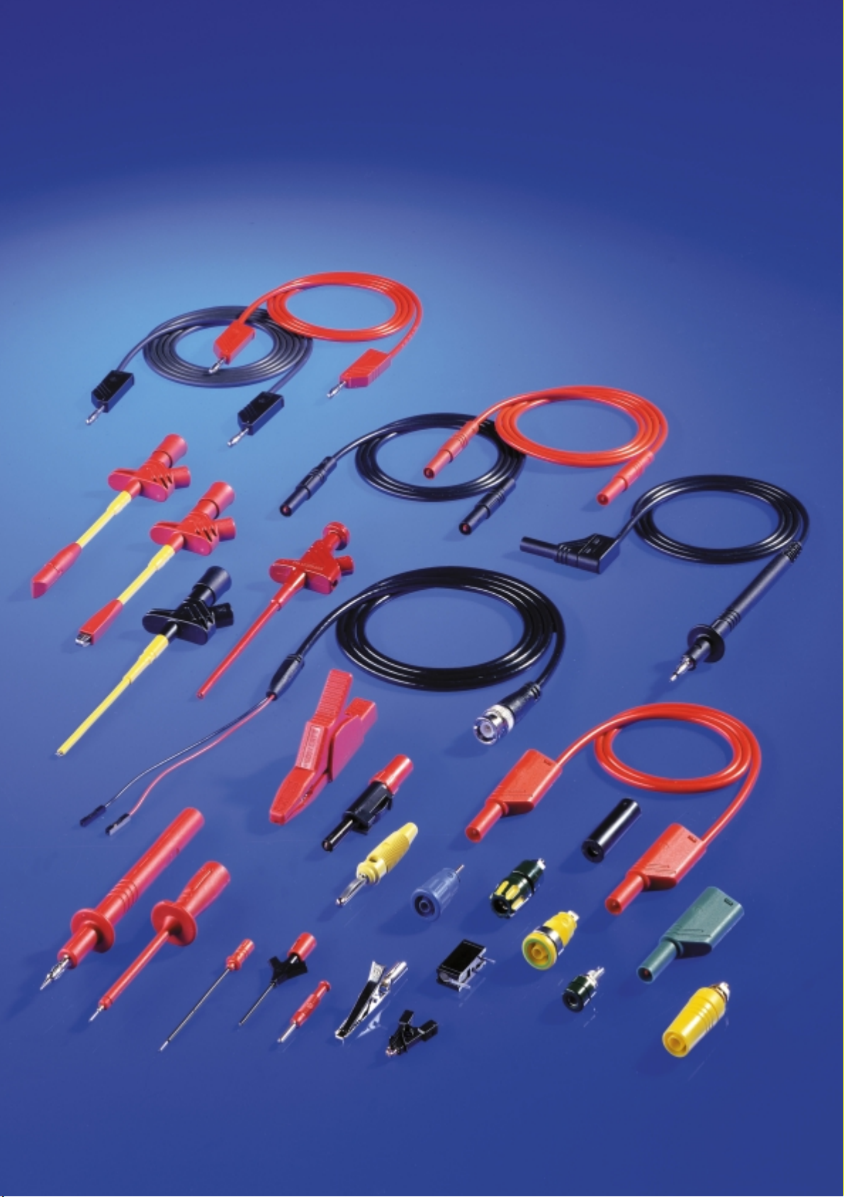
Edition 1
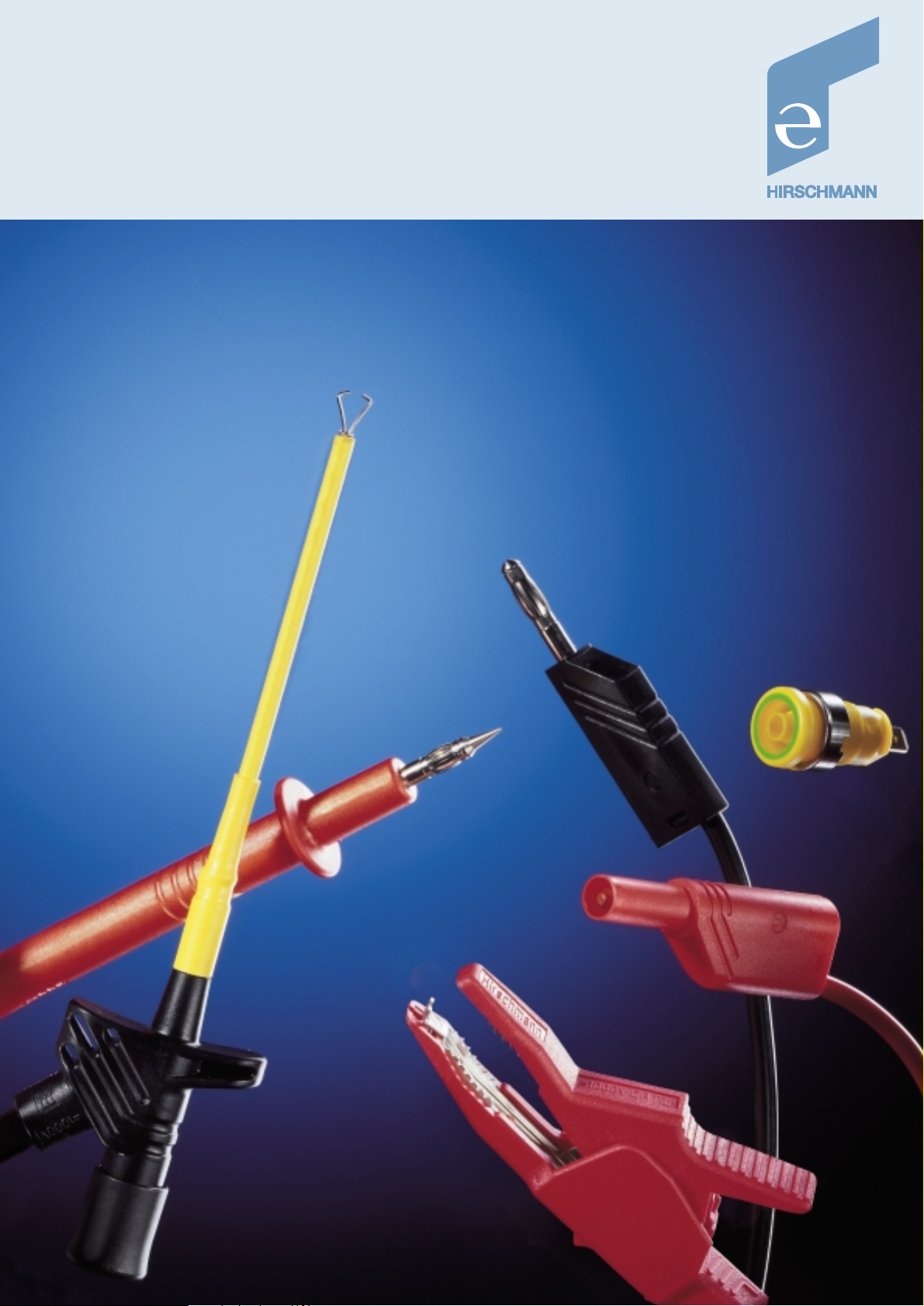
measuring and testing accessories
Whether pole clamps, test probes
or banana plugs, Hirschmann measuring
and testing accessories have
long been indispensable aids for the
transmission of measurement data,
voltages and currents, hence their
use in R&D laboratories, test bays and
workshops, service facilities, schools,
training centres and institutes.
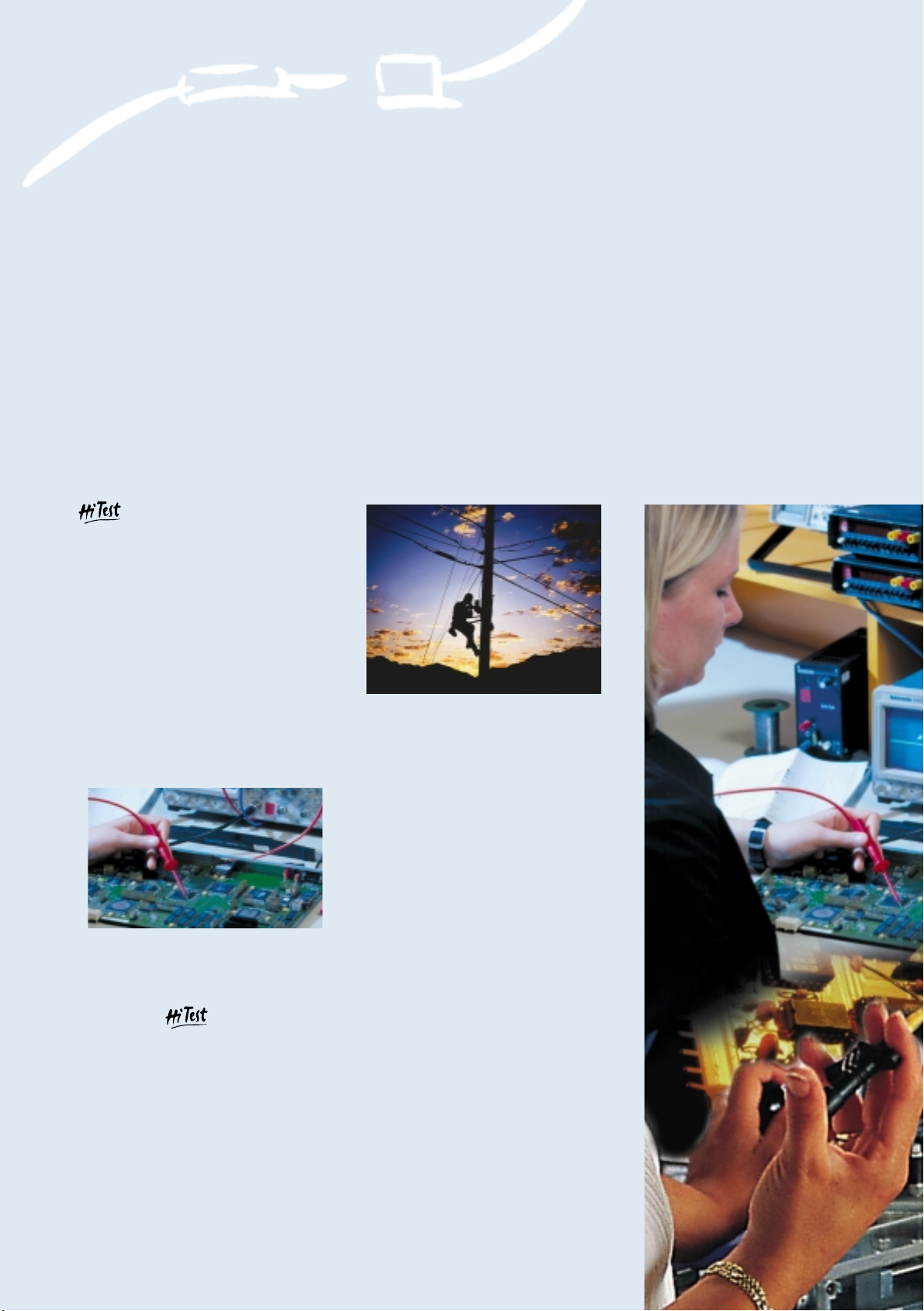
A must in research and technology
Hirschmann measuring
and testing products comprise a
comprehensive range of shockproof
measuring leads and accessories.
From miniature connectors for safety
extra-low voltage to safety-type products
for measuring tasks up to 1.000 V.
Connectivity Measuring and Testing Accessories
Precision and reliability
in research and technology
For all types of measuring and testing equipment
The high-quality materials used for
the contacts of plug pins and sockets
made of tin- or gold-plated brass or
copper beryllium, affording outstanding
connection, ensure consistent contact
quality over prolonged time periods.
For all types of measuring and testing
equipment.
To achieve the optimum degree of
protection for users of hand-held
measuring accessories, the entire
product range is provided with
double-strength reinforced insulation.
Hirschmann attaches considerable
importance to ergonomics and design,
providing the user with the optimum
degree of protection against electric
shocks and other hazards.

FULL-SPECTRUM SOLUTIONS
FROM THE SPECIALIST
Seeking dialogue, among ourselves and
with users. Developing innovative ideas
together. Making use of synergies.
Establishing productive links. And this
via state-of-the-art communication
technologies to transmit voice, data
and visual information. From modern
antenna systems in automobiles, satel-
lite reception and transmission systems
to enterprise-wide network solutions.
The Hirschmann Group, a subsidiary of
ADITRON AG, employs some 2,700
people around the world who are all
committed to achieving this vision.
AUTOMATION AND
NETWORK SOLUTIONS
DIVISION
With its connectors, fieldbus and fiber
optic systems, Hirschmann offers
automation solutions in bus, sensor
and actuator category. A broad range
of connectors for measuring and
testing applications, machine and
plant construction as well as building
technology are incorporated into the
program as well. Industry-specific
solutions for company-wide data
networks from the workgroup to the
backbone, from industrial to office
networking, from LAN to WAN complete
our range. In all commonly used
standards - with a focus on ETHERNET,
Fast ETHERNET and Gigabit ETHERNET.
4
Measuring Highlights
Measuring Highlights
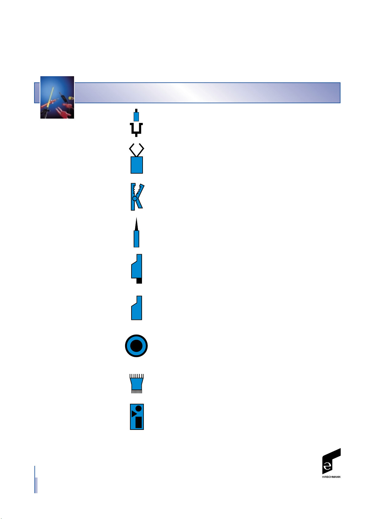
Table of contents
Description of systems . . . . . . . . . . . . . . . . . 6 – 7
Clamp-type test probes . . . . . . . . . . . . . . . . . 8 – 9
Alligator clips . . . . . . . . . . . . . . . . . . . . . . . 10 – 11
Test probes . . . . . . . . . . . . . . . . . . . . . . . . . 12 – 13
Measuring leads . . . . . . . . . . . . . . . . . . . . . 14 – 19
Plugs . . . . . . . . . . . . . . . . . . . . . . . . . . . . 20 – 23
Sockets . . . . . . . . . . . . . . . . . . . . . . . . . . . 24 – 27
IC testers . . . . . . . . . . . . . . . . . . . . . . . . . . 28
Sets . . . . . . . . . . . . . . . . . . . . . . . . . . . . . 29 – 30
M
0,64 mm
2 mm
4 mm
6
Measuring Highlights
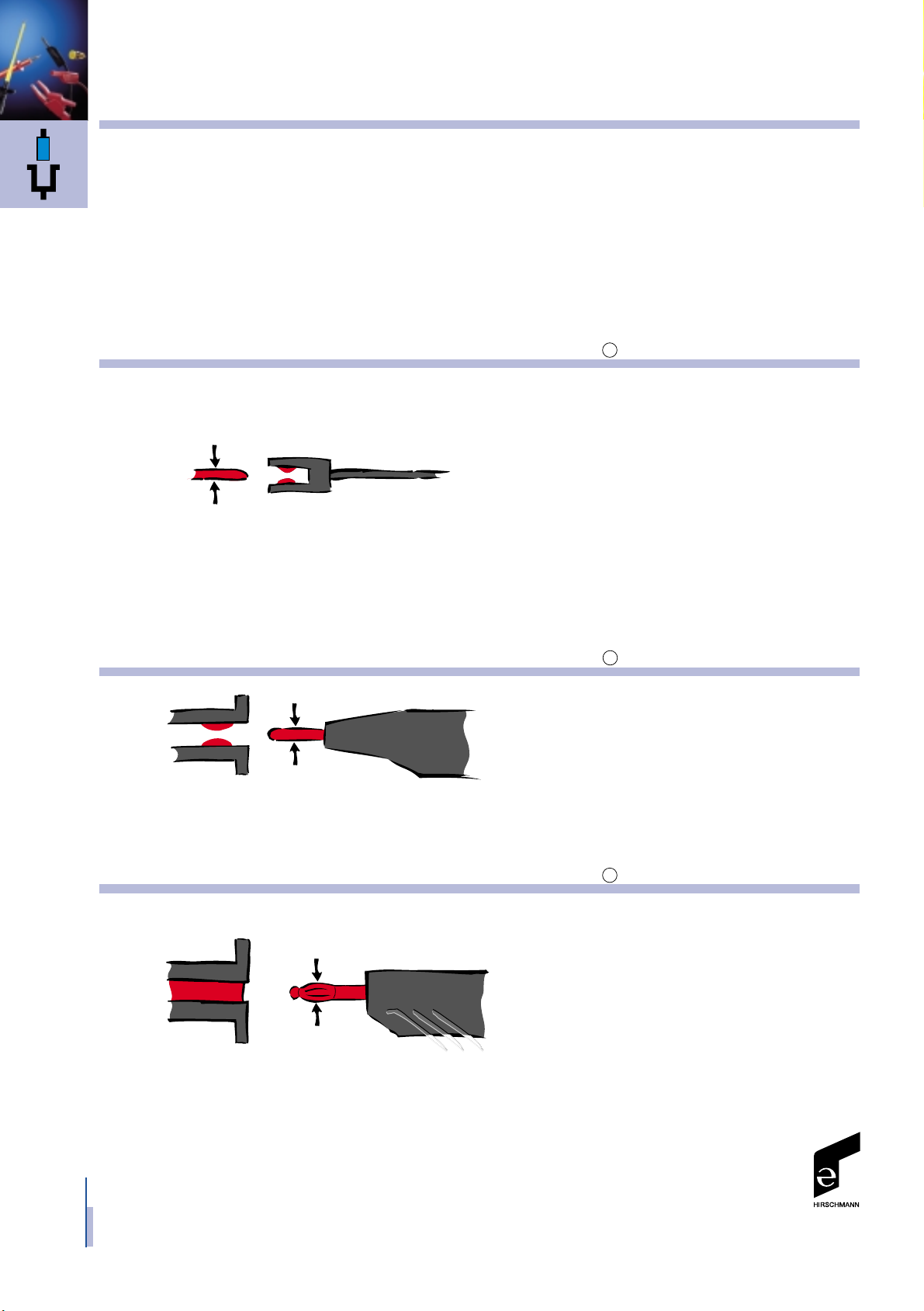
Descriptions of systems IEC 60947-5-2
0.64 mm system
The 0.64 mm system is compatible
with standard 0.64 mm printed
circuit board plugs. Miniature contacts,
fully protected with high-quality contact
material ensures efficient connecting
and prolonged endurance.
With this system, exceptionally
small components and measuring
points can be tested.
Max. 60 V
2 mm system
The 2 mm system consists of a
solid contact pin and a spring-loaded
socket. As a result, the small,
high-quality contact pin is protected
against mechanical influences.
Max. 60 V
4 mm system
The 4 mm system comprises a
spring-loaded contact pin and
springless sockets. A variety of
compatible contact techniques enable
the user to resolve any individual
problem. 4 mm plugs can be used
in combination with safety
sockets, clamp-type test probes,
crocodile clips, etc.
Max. 60 V
System designations are assigned
to the products on the following
pages. Unmarked products are
unrelated to a system and can be used
in combination with any system.
The catalogue is subdivided into
sections according to applications,
e.g. testing with test probes or
establishing connections with
measuring leads.
All the products are assigned to a
system and are fully compatible
within that system.
2
4
.64
4 mm
4 mm
7
Measuring Highlights
Descriptions of systems
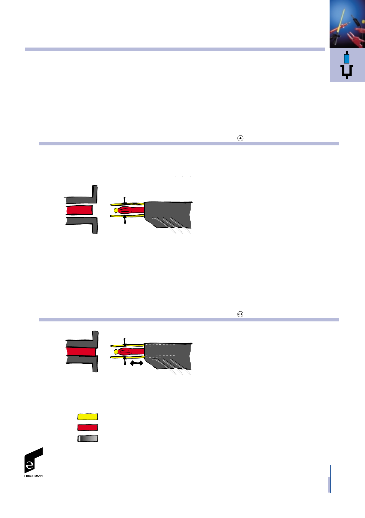
4 mm safety system
The 4 mm safety system comprises
a 4 mm pin with contact spring.
The pin is protected against physical
contact by a plastic coating and
the tip by a plastic cap. The system
is completely shockproof and
short circuit proof. 4 mm plugs
can be plugged into safety sockets
(SEB..., KLEPS..., AK...).
The component with the lowest
electric strength determines the
maximum permissible voltage of
the whole system.
The system complies with IEC 1010
(EN 61 010).
Max. 1000 V
4 mm sliding sleeve system
The 4 mm sliding sleeve system is
a safety system which provides
protection against physical contact by
means of a sliding locking spring.
The system can be used in combination
with any 4 mm system.
Max. 300 V
Total insulation
Contacts
Housing
8
Measuring Highlights
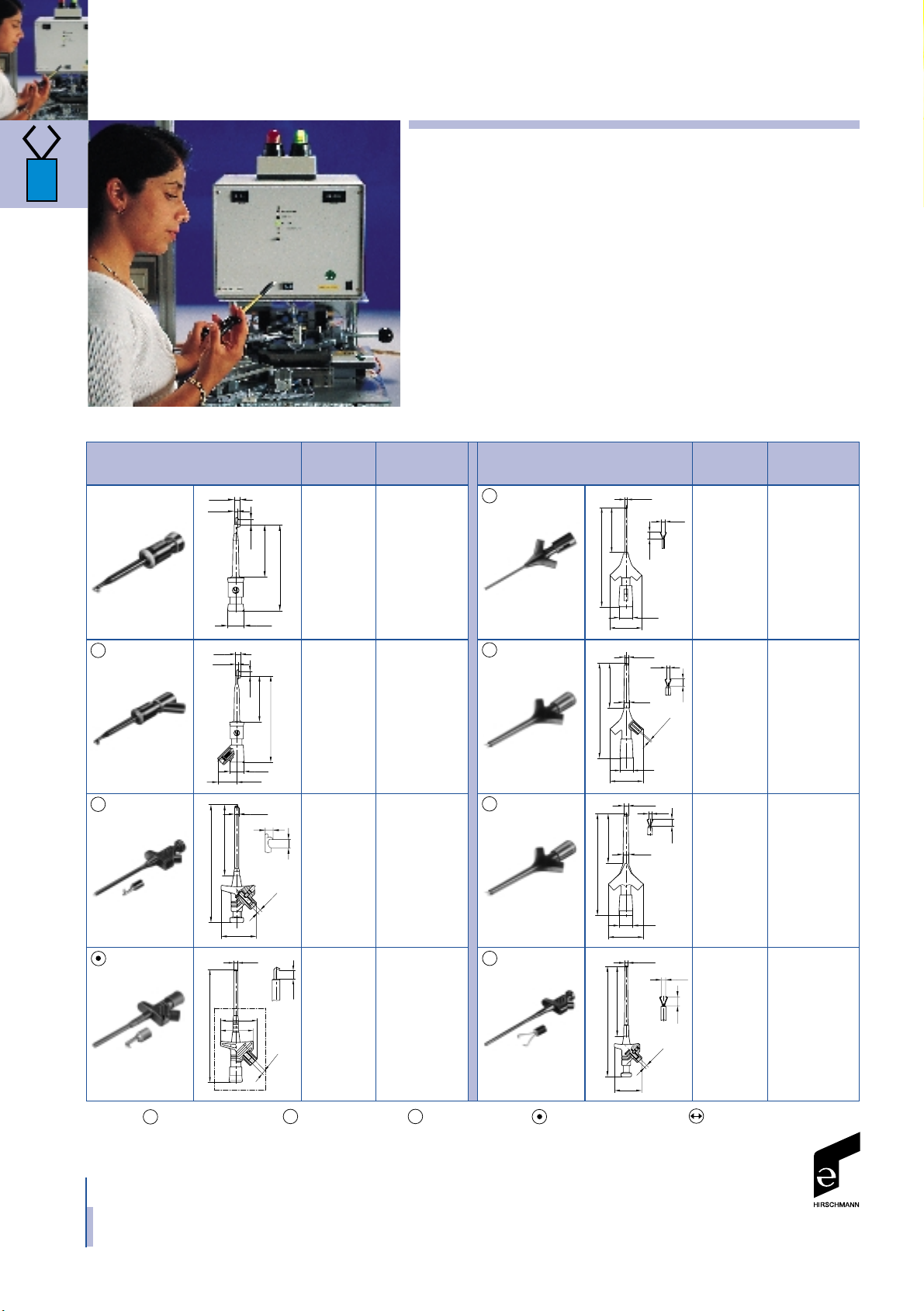
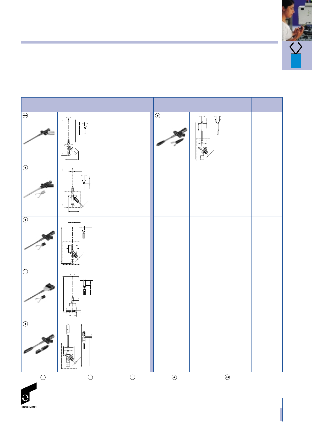
Clamp-type test probes
IEC 60947-5-2
Product description
Clamp-type test probes provide
the simple, rapid measurement of
voltages.
A variety of types and sizes
permit the measuring point to be
accessed and gripped without
difficulty.
The ergonomic design has been
optimised to facilitate handling to
the utmost extent.
The KLEPS 2700 permits a lead
to be tested without the insulation
being stripped.
The KLEPS 2800 is provided with
claw-type clamps with which large
test specimens can be gripped.
It is also suitable for testing
currents. The classic KLEPS 30,
used in millions of applications
worldwide, serves as a versatile
voltage tap.
931 467-100 ●
931 467-101 ●
973 972-100 ●
973 972-101 ●
Very thin
wires and
densely
packed
contact
points,
clamping
range
ø 2 mm
Clamping
range max.
ø 2 mm,
contact
hook,
solder
contact
Clamping
range max.
ø 2 mm,
contact
hook
20 A
clamping
range max.
ø 2 mm
20 A
clamping
range
5.5 mm
Very thin
wires and
densely
packed
contact
points,
clamping
range
ø 3.5 mm
Very thin
wires and
densely
packed
contact
points,
clamping
range
ø 3.5 mm
Clamping
range
ø 4 mm
973 501-100 ●
973 501-101 ●
973 592-100 ●
973 592-101 ●
930 111-100 ●
930 111-101 ●
973 649-100 ●
973 649-101 ●
972 309-100 ●
972 309-101 ●
930 113-100 ●
930 113-101 ●
2
.64
.64
4
.64
4
*
System Technical Order no.
Article type Data Colour
*
System Technical Order no.
Article type Data Colour
KLEPS 2
KLEPS 2-BU
KLEPS 10
MICRO-KLEPS
KLEPS 3 ST
KLEPS 4
KLEPS 2900 KLEPS 30
57.5
ø 11
35
3.5
ø 2
3.8
3.6
1.6
53.8
24
ø 1.4
18
ø 7.5
ø 0.64
52
24
18
ø 7
2
4
ø 3
ø 2.3
8
ø 4
3.5
39.5
ø 4.1
100
158
66
ø 11
35
14.5
3.5
ø 2
3.8
ø 2mm Steckerstift
3.8
ø 4
ø 4.5
3.4
39.5
77
128.5
126
5.5
ø 4
4.3
41
36.5
Griffbereich
*
System: = 0.64 mm system / ^= 2 mm system / ^= 4 mm system / ^= 4 mm safety system / ^= 4 mm sliding sleeve system
2
4
.64
ø 2.3
24
ø 3
52
2
4
ø 7
ø 18
972 378-100 ●
972 378-101 ●
973 528-100 ●
973 528-101 ●
972 308-100 ●
972 308-101 ●
972 306-100 ●
972 306-101 ●
973 053-100 ●
973 053-101 ●
972 307-100 ●
972 307-101 ●
4
*
System Technical Order no.
Article type Data Colour
*
System Technical Order no.
Article type Data Colour
KLEPS 2000
KLEPS 250
KLEPS 2600
KLEPS 60
KLEPS 2800
KLEPS 2700
Hirschmann
Griffbereich
9
3.5
ø 4
156
ø 4.5
45
8
3.5
158
100
60
1.14
min.10
8.3
157
6
32
ø 4
41
36.5
Griffbereich
Griffbereich
3.9
160.5
3.5
41
36.5
ø 4
ø 4
ø 2
8
3.5
148
32
100
ø 4
4.2
162
41
36.5
ø 4
Griffbereich
gefederte Edelstahlspitze
9
Measuring Highlights
Clamp-type test probes
300 V =
clamping
range
ø 4 mm
Clamping
range
ø 4 mm
Clamping
range
ø 4 mm
Clamping
range
ø 4 mm
0.25 mm2up
to 1.5 mm
2
(ø 3.5 mm)
contact
without the
need to
strip them
„Piercing
Clip“
20 A
clamping
range
ø 10 mm,
grip claws
*
System: = 0.64 mm system / ^= 2 mm system / ^= 4 mm system / ^= 4 mm safety system / ^= 4 mm sliding sleeve system
2
4
.64
10
Measuring Highlights
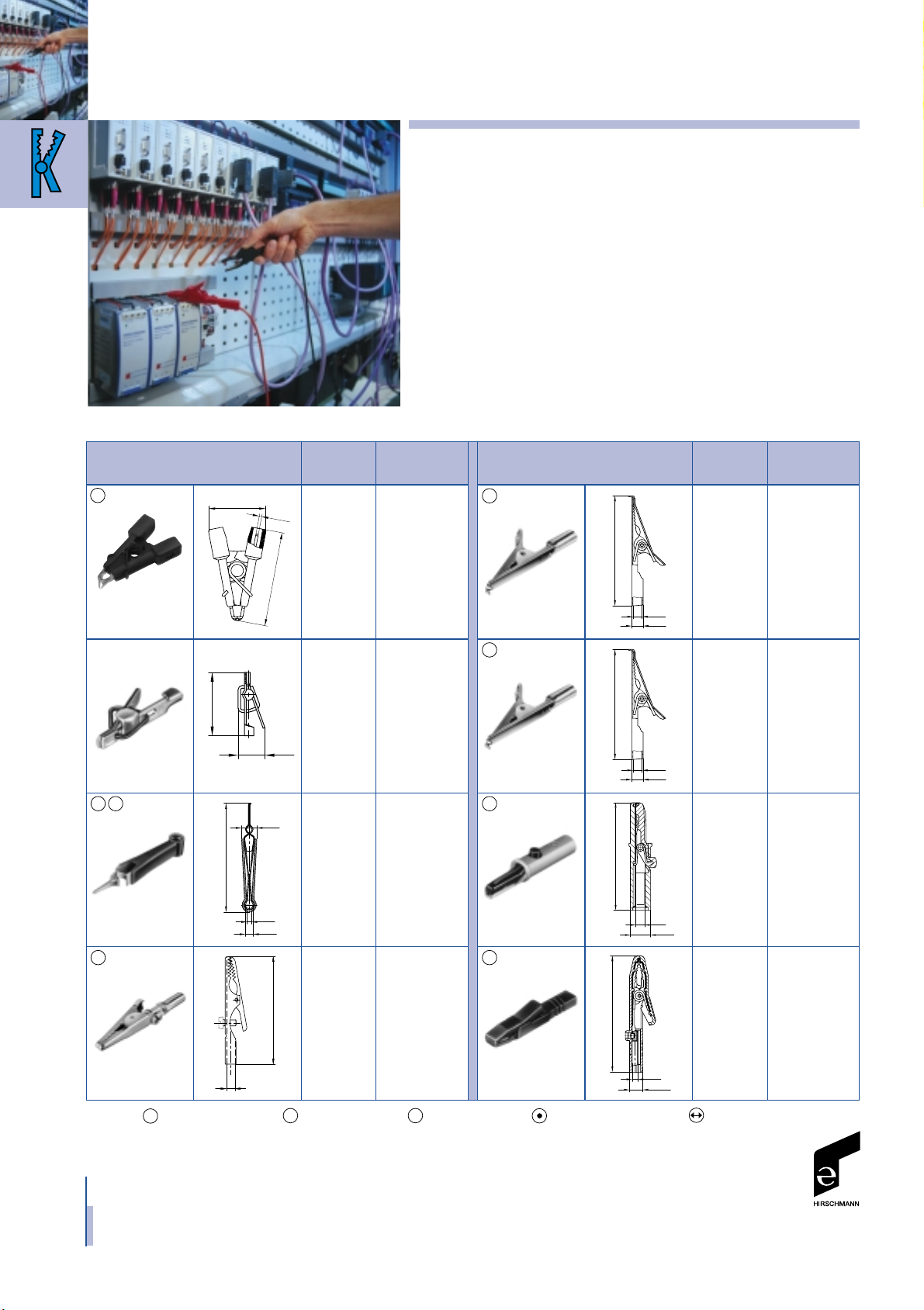
Alligator clips IEC 60947-5-2
Product description
Alligator clips, also known as
crocodile clips, are outstandingly
suitable for the testing and
transfer of currents.
The sharp teeth of the clips bite
into the test specimen with little
contact resistance.
Thanks to their thin wire clamping
capability, they are able to make
contact with extra finely stranded
conductors of minimal cross
sections.
Opening widths up to 30 mm
permit large contacts to be
securely gripped.
The MICRO-SMD CLIP is used
for the two-pole testing of very
small SMD components.
Crocodile clips are also widely
used in non-electrical applications.
972 416-100 930 120-000
930 476-001 930 122-000
931 272-100 ●
931 272-101 ●
930 126-100 ●
930 126-601 ●
930 126-102 ●
930 126-103 ●
930 126-104 ●
603 006-001 932 146-100 ●
932 146-101 ●
24444
4
4
*
System Technical Order no.
Article type Data Colour
*
System Technical Order no.
Article type Data Colour
AGF 1
AGF 2
AGF 20
AGF 30
AK 10
AGS 20 AK 2 S
15
25
F
0.64
ø 5
ø 4
49
ø 5
ø 4
49
10ø
ø 4
53
9 x 13
ø 4
80.5
7
17
ø 4
ø 2
7.5
53.5
ø4
49.5
MICRO-SMD
CLIP 1
Clamping
range
up to 4 mm
2-pole
test clip,
clamping
range
0 up to
8mm
Solder
contact
Stainless
steel,
rust and
acid-proof,
nonmagnetic
6 A
clamping
range max.
6mm
25 A
clamping
range max.
9.5 mm
Terminal
screw,
clamping
range max.
5mm
*
System: = 0.64 mm system / ^= 2 mm system / ^= 4 mm system / ^= 4 mm safety system / ^= 4 mm sliding sleeve system
2
4
.64
.64

973 584-100 ●
973 584-101 ●
930 317-800 ●
930 317-801 ●
973 889-100 ●
973 889-101 ●
932 435-100 ●
932 435-101 ●
972 405-100 ●
972 405-101 ●
2
2
*
System Technical Order no.
Article type Data Colour
MA 1 S
MA 1
MA 260 SH
AK 2 B
AK 2 B 2540 I
15
ca.13
41.5
2ø
4.95ø
15
ca.13
41.5
2ø
4.95ø
56
16
ø 4
11*11.5
ø 4
4.5
81
ø 4
5.5
85
ø 30
11
Measuring Highlights
Alligator clips
15 A
300 V
clamping
range
ø 6 mm
25 A
300 V
clamping
range
ø 9.5 mm
34 A
clamping
range
ø 30 mm
Rust and
acid-proof,
clamping
range
up to 4 mm
Clamping
range
up to 4 mm
Notes
*
System: = 0.64 mm system / ^= 2 mm system / ^= 4 mm system / ^= 4 mm safety system / ^= 4 mm sliding sleeve system
2
4
.64

12
Measuring Highlights
Test probes
IEC 60947-5-2
Product description
Test probes are used for voltage
testing purposes.
Their needle-like steel tips
penetrate oxidation layers,
thereby establishing an effective
connection with the test
specimen.
The spring-loaded prods of
the MICRO-PRUEF and
PRUEF 2610 FT make contact
with sensitive components with
gently applied spring force.
Contact with less vulnerable
contact points can be established
with the PRUEF 2700, which is
also equipped with a 4 mm pin.
The SS 260 prod guard protects
the user from injury and ICs from
short circuits.
931 376-100 ●
931 376-101 ●
973 505-100 ●
973 505-101 ●
973 995-100 ●
973 995-101 ●
973 368-100 ●
973 368-101 ●
973 531-100 ●
973 531-101 ●
973 659-100 ●
973 659-100 ●
930 227-100 ●
930 227-101 ●
972 317-100 ●
972 317-101 ●
4
4
.64
2
*
System Technical Order no.
Article type Data Colour
*
System Technical Order no.
Article type Data Colour
PRUEF 1
MPS 1
PRUEF 20
PRUEF 2
PRUEF 2 S
PRUEF 10 PRUEF 2600
90
39
ø 2
ø 1
45°
Kabeldurchmesser max. 2mm
ø 4
110
17
10
PrQf 20
ø 4
ø 4.3
97.5
61.5
7.5
ø 12
ø 2
7.5
20
15
119
61.5
ø 2
ø 4.3
34.5
ø 2
19
21
98
ø 13
ø 4
Griffbereich
ø 1.6
68.9
16
30°
6.9
ø 0.75
ø 0.64
ø 5
ø 6.5
45°
ø 7.5
32
3.5
86
Kontaktlamelle für
ø2mm Steckerstift
ø 10
ø 2
10
ø 4
17
137
MICRO-PRUEF
MPS 2/0,64 FT
Sprung
probe tip
Solder
contact
Solder
contact
*
System: = 0.64 mm system / ^= 2 mm system / ^= 4 mm system / ^= 4 mm safety system / ^= 4 mm sliding sleeve system
2
4
.64

972 319-100 ●
972 319-101 ●
972 318-100 ●
972 318-101 ●
973 865-001
*
System Technical Order no.
Article type Data Colour
PRUEF 2700
PRUEF 2610 FT
SS 260
3
1
1.8
ø 6
20
13
Measuring Highlights
Test probes
Sprung
stainless
steel tip
Contact
protector,
contact
help for ICs
Notes
*
System: = 0.64 mm system / ^= 2 mm system / ^= 4 mm system / ^= 4 mm safety system / ^= 4 mm sliding sleeve system
2
4
.64
ø 0.75
ø 4.3
99.5
Griffbereich
ø 4
ø 13
ø 4
Griffbereich
19
5.5
130
90
19
20
ø 4
ø 11

14
Measuring Highlights
Measuring leads IEC 60947-5-2
Product description
Measuring leads connect
hardware items such as machines,
test equipment, measuring
instruments, experimental
set-ups, etc. A variety of types
permits optimised cable layouts,
expansion facilities through
stacking and use in differing
voltage ranges.
The selection of special-purpose
insulating material and crosssections ensures adaptability
and high loading capacities.
A special cable configuration
incorporates a white tell-tale
mark, indicating possible
mechanical damage and
a consequential risk to the user.
Testing leads, which are typical
accessories for multimeters,
consist of measuring leads with
test probes.
MLS GG 25/1 25 cm 1 mm2, PVC 934 070-Colour**
16 A ● ● ● ● ● ●
MLS GG 25/2,5 25 cm 2,5 mm2, PVC 934 071-Colour**
32 A ● ● ● ● ●●●
MLS GG 50/1 50 cm 1 mm
2
, PVC 934 072-Colour**
16 A ● ● ● ● ●
MLS GG 50/2,5 50 cm 2,5 mm
2
, PVC 934 073-Colour**
32 A ● ● ● ● ●●●
MLS GG 100/1 100 cm 1 mm2, PVC 934 074-Colour**
16 A ● ● ● ● ●
MLS GG 100/2,5 100 cm 2,5 mm
2
, PVC 934 075-Colour**
32 A ● ● ● ● ●●●
MLS GG 200/1 200 cm 1 mm
2
, PVC 934 076-Colour**
16 A ● ● ● ● ●
MLS GG 200/2,5 200 cm 2,5 mm2, PVC 934 077-Colour**
32 A ● ● ● ● ●●●
*
System Article type Length Technical Order no.
”L“ in cm Data Colour
**
Colour: ●-100 ●-101 ●-102 ●-103 ● -104 ●●-188
*
System: = 0.64 mm system / ^= 2 mm system / ^= 4 mm system / ^= 4 mm safety system / ^= 4 mm sliding sleeve system
2
4
.64

*
System: = 0.64 mm system / ^= 2 mm system / ^= 4 mm system / ^= 4 mm safety system / ^= 4 mm sliding sleeve system
2
4
.64
MLS WG 25/1 25 cm 1 mm2, PVC 934 078-Colour**
16 A ● ● ● ● ● ●
MLS WG 25/2,5 25 cm 2,5 mm2, PVC 934 079-Colour**
32 A ● ● ● ● ●●●
MLS WG 50/1 50 cm 1 mm
2
, PVC 934 080-Colour**
16 A ● ● ● ● ●
MLS WG 50/2,5 50 cm 2,5 mm
2
, PVC 934 081-Colour**
32 A ● ● ● ● ●●●
MLS WG 100/1 100 cm 1 mm2, PVC 934 082-Colour**
16 A ● ● ● ● ●
MLS WG 100/2,5 100 cm 2,5 mm
2
, PVC 934 083-Colour**
32 A ● ● ● ● ●●●
MLS WG 200/1 200 cm 1 mm
2
, PVC 934 084-Colour**
16 A ● ● ● ● ●
MLS WG 200/2,5 200 cm 2,5 mm2, PVC 934 085-Colour**
32 A ● ● ● ● ●●●
*
System Article type Length Technical Order no.
”L“ in cm Data Colour
15
Measuring Highlights
Measuring leads
**
Colour: ●-100 ●-101 ●-102 ●-103 ● -104 ●●-188

16
Measuring Highlights
Measuring leads IEC 60947-5-2
MLS WS 25/1 25 cm 1mm2, PVC 934 067-Colour**
16 A ● ● ● ● ● ●
MLS WS 25/2,5 25 cm 2,5mm2, PVC 934 086-Colour**
32 A ● ● ● ● ●●●
MLS WS 50/1 50 cm 1mm
2
, PVC 934 068-Colour**
16 A ● ● ● ● ●
MLS WS 50/2,5 50 cm 2,5mm
2
, PVC 934 087-Colour**
32 A ● ● ● ● ●●●
MLS WS 100/1 100 cm 1mm2, PVC 934 095-Colour**
16 A ● ● ● ● ●
MLS WS 100/2,5 100 cm 2,5mm
2
, PVC 934 088-Colour**
32 A ● ● ● ● ●●●
MLS WS 200/1 200 cm 1mm
2
, PVC 934 069-Colour**
16 A ● ● ● ● ●
MLS WS 200/2,5 200 cm 2,5mm2, PVC 934 089-Colour**
32 A ● ● ● ● ●●●
*
System Article type Length Technical Order no.
”L“ in cm Data Colour
**
Colour: ●-100 ●-101 ●-102 ●-103 ● -104 ●●-188
*
System: = 0.64 mm system / ^= 2 mm system / ^= 4 mm system / ^= 4 mm safety system / ^= 4 mm sliding sleeve system
2
4
.64

MLN 25/1 25 cm 1 mm2, PVC 934 058-Colour**
16 A ● ● ● ● ● ●
MLN 25/2,5 25 cm 2,5 mm2, PVC 934 059-Colour**
32 A ● ● ● ● ●●●
MLN 50/1 50 cm 1 mm
2
, PVC 934 060-Colour**
16 A ● ● ● ● ●
MLN 50/2,5 50 cm 2,5 mm2, PVC 934 061-Colour**
32 A ● ● ● ● ●●●
MLN 100/1 100 cm 1 mm2, PVC 934 062-Colour**
16 A ● ● ● ● ●
MLN 100/2,5 100 cm 2,5 mm2, PVC 934 063-Colour**
32 A ● ● ● ● ●●●
MLN 150/1 150 cm 1 mm
2
, PVC 934 064-Colour**
16 A ● ● ● ● ●
MLN 200/1 200 cm 1 mm
2
, PVC 934 065-Colour**
16 A ● ● ● ● ●
MLN 200/2,5 200 cm 2,5 mm2, PVC 934 066-Colour**
32 A ● ● ● ● ●●●
*
System Article type Length Technical Order no.
”L“ in cm Data Colour
4
17
Measuring Highlights
Measuring leads
*
System: = 0.64 mm system / ^= 2 mm system / ^= 4 mm system / ^= 4 mm safety system / ^= 4 mm sliding sleeve system
2
4
.64
**
Colour: ●-100 ●-101 ●-102 ●-103 ● -104 ●●-188

18
Measuring Highlights
Measuring leads IEC 60947-5-2
MLN SIL 50/1 50 cm 1 mm2, Silicon 934 091-Colour**
16 A ● ● ● ● ● ●
MLN SIL 25/1 25 cm 1 mm2, Silicon 934 090-Colour**
16 A ● ● ● ● ● ●
MLN SIL 100/1 100 cm 1 mm
2
, Silicon 934 092-Colour**
16 A ● ● ● ● ●
MLN SIL 150/1 150 cm 1 mm
2
, Silicon 934 093-Colour**
16 A ● ● ● ● ●
MLN SIL 200/1 200 cm 1 mm
2
, Silicon 934 094-Colour**
16 A ● ● ● ● ●
MLB 25/1 V 25 cm 1 mm
2
, PVC 973 644-Colour**
16 A ● ● ● ● ●
60 V DC
MLB 50/1 V 50 cm 1 mm
2
, PVC 973 645-Colour**
16 A ● ● ● ● ●
60 V DC
MLB 100/1 V 100 cm 1mm
2
, PVC 973 646-Colour**
16 A ● ● ● ● ●●●
60 V DC
MLB 200/1 V 200 cm 1mm
2
, PVC 973 647-Colour**
16 A ● ● ● ● ●
60 V DC
PL 2600 S W 100 cm 1 mm
2
, PVC 934 158-Colour**
16 A ● ●
Angle plug
PL 2600 S 100 cm 1 mm
2
, PVC 934 159-Colour**
16 A ● ●
Straight plug
*
System Article type Length Technical Order no.
”L“ in cm Data Colour
"L"
62.5
ø 6.5
17
23
19.4
ø 4
ø 4
ø 4
ø 20
ø 9.5
1000
135
21.5
ø 4
ø 4
46.3
**
Colour: ●-100 ●-101 ●-102 ●-103 ● -104 ●●-188
*
System: = 0.64 mm system / ^= 2 mm system / ^= 4 mm system / ^= 4 mm safety system / ^= 4 mm sliding sleeve system
2
4
.64
4

MVL 2/25 25 cm 0,5 mm2, PVC 973 594-Colour**
6 A, 17 mΩ ● ●
MVL 2/50 50 cm 0,5 mm
2
, PVC 973 595-Colour**
6 A, 26 mΩ ● ●
MVL 2/100 100 cm 0,5 mm
2
, PVC 973 596-Colour**
6 A, 44 mΩ ● ●
MKL 0,64/25-0,25 25 cm 0,25 mm
2
, PVC 973 604-Colour**
3 A ● ●
BNC - AL 0,64 120 cm RG 58 A/U 933 844-001
MAL N 4-0,64/100-0,25 100 cm 0,25 mm
2
, PVC 934 160-Colour**
3 A ● ●
LMLH 50 30 plastic 973 919-001
brackets
*
System Article type Length Technical Order no.
”L“ in cm Data Colour
"L"
32
12
9
ø 2
Buchse für 2mm Stecker
ø 2
Buchse für 0.64mm Pfosten
250
14
2.5
1.5
ca. 100 ca. 30 ca. 1200
ø 1.5
14
2.5
1000
20
ø 7.5
33
ø 4
ø 4.6
12
61.4
500
Hirschmann
2
.64
.64
4
.64
19
Measuring Highlights
Measuring leads
*
System: = 0.64 mm system / ^= 2 mm system / ^= 4 mm system / ^= 4 mm safety system / ^= 4 mm sliding sleeve system
2
4
.64
**
Colour: ●-100 ●-101 ●-102 ●-103 ● -104 ●●-188

20
Measuring Highlights
Plugs IEC 60947-5-2
Product description
Plugs and connectors permit
users to assemble their own
measuring and testing leads.
A variety of contact-making
and connecting systems offer
the ideal solution for every
application. Safety plugs with
screw connectors comply with
IEC 1010 and can be used for
voltages up to 1000 V.
Connectors permit the assembly
of extensions and connecting
leads.
All the products are simply
plugged, screwed or soldered
together without the need for
specialised tools.
930 726-100 ●
930 726-101 ●
930 726-102 ●
930 726-103 ●
930 726-104 ●
*
System Technical Order no.
Article type Data Colour
*
System Technical Order no.
Article type Data Colour
BUELA 20 K
ø 11
ø 4.2
60.5
40
4
ø 4
16 A
screw
connection
max.
1.5 mm
2
4
934 099-100 ●
934 099-101 ●
934 099-102 ●
934 099-103 ●
934 099-104 ●
LAS S WS
20 A
screw
connection
up to
1.5 mm
2
972 320-100 ●
972 320-101 ●
SLS 2000 SH
ø 4.1
22.3
54.5
ø 7.8
ø 4
ø 6.4
ø 4
25 A
screw
connection
up to
2.5 mm
2
934 097-100 ●
934 097-101 ●
934 097-102 ●
934 097-103 ●
934 097-104 ●
LAS S G
20 A
screw
connection
max.
1.5 mm
2
934 098-100 ●
934 098-101 ●
934 098-102 ●
934 098-103 ●
934 098-104 ●
LAS S W
20 A
screw
connection
up to
1.5 mm
2
934 100-100 ●
934 100-101 ●
934 100-102 ●
934 100-103 ●
934 100-104 ●
LAS N WS
20 A
screw
connection
up to
1.5 mm
2
4
972 518-100 ●
972 518-101 ●
4
LAS 30
40
60
ø 11
ø 4.2
ø 4
20 A
solder
contact
up to
1.5 mm
2
930 727-100 ●
930 727-101 ●
930 727-102 ●
930 727-103 ●
930 727-104 ●
BUELA 30 K
30 A
solder
contact
max.
2.5 mm
2
ø 11
ø 4.2
60.5
40
ø 4
ø 4
4
*
System: = 0.64 mm system / ^= 2 mm system / ^= 4 mm system / ^= 4 mm safety system / ^= 4 mm sliding sleeve system
2
4
.64

930 729-100 ●
930 729-101 ●
930 729-102 ●
930 729-103 ●
930 729-104 ●
931 294-100 ●
931 294-101 ●
931 667-100 ●
931 667-101 ●
931 667-102 ●
931 667-103 ●
931 667-104 ●
*
System Technical Order no.
Article type Data Colour
*
System Technical Order no.
Article type Data Colour
BSB 20 K
BSB 300
BUELA 300 K
ø 4
56
35.6
ø 4
15.5
60.5
41
ø 4
16
ø 4
ø 4
ø 4
22.5
ø 4
40
60.5
21
Measuring Highlights
Plugs
30 A
screw
connection
max.
2.5 mm
2
16 A
solder
contact
max.
1.5 mm
2
30 A
solder
contact
max.
2.5 mm
2
930 046-100 ●
930 046-101 ●
930 046-102 ●
930 046-103 ●
930 046-104 ●
ø 10
51
3.831ø
ø 4
16 A
screw
connection
max.
1.5 mm
2
VON 20
4
930 047-100 ●
930 047-101 ●
930 047-102 ●
930 047-103 ●
930 047-104 ●
VON 30
ø 10
3.8ø
51
31
ø 4
30 A
solder
contact
max.
2.5 mm
2
4
930 058-100 ●
930 058-101 ●
930 058-102 ●
930 058-103 ●
930 058-104 ●
VQ 20
ø 11
59.5
ø 4.2
40
ø 4
16 A
screw
connection
max.
1.5 mm
2
4
930 061-100 ●
930 061-101 ●
930 061-102 ●
930 061-103 ●
930 061-104 ●
930 435-100 ●
930 435-101 ●
930 435-102 ●
930 435-103 ●
930 435-104 ●
VQ 30
VSB 20
ø 11
59.5
40
ø 4
ø 4.2
15.5
55
ø 4
35.5
ø 4
30 A
solder
contact
max.
2.5 mm
2
30 A
screw
connection
max.
2.5 mm
2
4
4
931 824-100 ●
931 824-101 ●
931 825-100 ●
931 825-101 ●
SLS 10 B
SLS 20 B
ø 4
ø 10
ø 12
ø 4.2
ø 6
67
20
ø 4
ø 6
ø 10
ø 12
ø 4.2
67
20
30 A
60 V DC
16 A
300 V
screw
connection
up to
1.5 mm
2
*
System: = 0.64 mm system / ^= 2 mm system / ^= 4 mm system / ^= 4 mm safety system / ^= 4 mm sliding sleeve system
2
4
.64
4
4
4

22
Measuring Highlights
Plugs IEC 60947-5-2
973 509-100 ●
973 509-101 ●
973 509-102 ●
973 509-103 ●
973 509-104 ●
973 509-106 ●
930 109-100 ●
930 109-101 ●
*
System Technical Order no.
Article type Data Colour
*
System Technical Order no.
Article type Data Colour
MST 3
KD 10
37
12
ø 2
ø 2.1
ø 4.8
10ø
ø 4
44
7ø
4
6 A
solder
contact
10 A
2
4
932 153-100 ●
932 153-101 ●
SLS 200
65
20
17.5
ø 4
ø 6
ø 4
30 A
300 V
screw
connection
up to
2.5 mm
2
930 581-000
VST 100
2.5
M 5
ø
34
21
ø 4
16 A
screw
connection
max.
1.5 mm
2
4
930 050-000
4
VST 20
M 4
ø 2
15
ø 4
3
23
16 A
solder
contact
max.
2mm
2
931 338-001
MST 201
2ø
14
10
1.3
4øø
1
2
934 096-100 ●
934 096-101 ●
934 096-102 ●
934 096-103 ●
934 096-104 ●
KUN S
931 804-100 ●
931 804-101 ●
931 804-102 ●
931 804-103 ●
931 804-104 ●
KUN 30
ø4
ø11
ø5.5
4.2
22
48
16 A
solder
contact
up to
2.5 mm
2
4
930 189-100 ●
930 189-101 ●
KUN 10
ø 11
4ø
36
16 A
screw
connection
up to
1.5 mm
2
4
930 320-100 ●
930 320-101 ●
MKU 1
39
2.1ø
20
72ø
ø
6 A
2
*
System: = 0.64 mm system / ^= 2 mm system / ^= 4 mm system / ^= 4 mm safety system / ^= 4 mm sliding sleeve system
2
4
.64

930 110-100 ●
930 110-101 ●
973 599-100 ●
973 599-101 ●
973 600-100 ●
973 600-101 ●
930 584-100 ●
930 584-101 ●
4
*
System Technical Order no.
Article type Data Colour
*
System Technical Order no.
Article type Data Colour
KB 20
MZS 4
MZS 2
KB 2
Buchse für 2mm Steckerstift
53.5
33.5
8
ø 4
ø 8
ø 4.5
45.5
12
ø 8
ø 4
ø 2
58.5
ø 11
ø 4.2
40
7.1
23
Measuring Highlights
Plugs
30 A
30 A
max.
2.5 mm
2
6 A
6 A
909 009-100 ●
909 009-101 ●
FLAK 2,8
12 A for tab
connectors
2.8x0.8 and
2.8 x 0.5
complying
with
DIN 46 244
crimp
connection
0.5 mm2up
to 0.75 mm
2
5
28
909 004-100 ●
909 004-101 ●
909 004-107
FLAK 6,3
35.5
5
16 A for tab
connectors
6.3 x 0.8
complying
with
DIN 46 244
crimp
connection
1.5 mm
2
up
to 2.5 mm
2
*
System: = 0.64 mm system / ^= 2 mm system / ^= 4 mm system / ^= 4 mm safety system / ^= 4 mm sliding sleeve system
2
4
.64
2 4
4 2
ø 10
7.1
12
53
35
ø 4

24
Measuring Highlights
Sockets IEC 60947-5-2
Product description
Sockets are built in equipment,
housings or panels and permit
the rapid, simple connection of
measuring leads, plugs or, when
configured as pole terminals,
the secondary connection of
leads and cable lugs.
Tin plated and gold plated
surfaces, and a choice of
connector cross sections, permit
the reliable transmission of
low-level signals and powerful
currents.
The insulation of the PKI 110
incorporates a spring which
permits leads to be efficiently
connected in the minimum of
time.
930 312-000 ● IEC 1010 930 177-000 ●
931 337-000 IEC 1010 930 224-100 ●
930 224-101 ●
IEC 1010 930 160-000 IEC 1010 973 582-100 ●
973 582-101 ●
IEC 1010 930 147-000 IEC 1010 930 308-100 ●
930 308-101 ●
930 308-102 ●
930 308-103 ●
930 308-104 ●
930 308-106 ●
2
4
24224
4
*
System Technical Order no.
Article type Data Colour
*
System Technical Order no.
Article type Data Colour
MBU 1
MBU 2
BO 10
BU 20
MPB 1
PB 4
BU 10 MBI 1
2.1
2
ø 6.5
ø
max.14.5
20.8
5.5
10.25
3.5
1.2
ø 2
5.8
0.25
ø 2
21
7
5
4
7.5
1.2
10.5
0.5
17.5
max.21
M 5
15
3.5
6.5
2ø
ø
max.6
1.3
18
2.1
ø
4
12.3
ø
ø
3
M 6 x 0.75
16
2.5
7.54øø
M 6 x 0.75
22
1.5
2.5
4
7.5øø
17.5
6 A 16 A
opening for
installation
ø 6 mm
6 A
16 A
6 A
6 A
16 A
opening for
installation
ø 6 mm
16 A
opening for
installation
ø 6 mm
M 6 x 0.75
27
1.5
22.5
4
7.5øø
2.5
*
System: = 0.64 mm system / ^= 2 mm system / ^= 4 mm system / ^= 4 mm safety system / ^= 4 mm sliding sleeve system
2
4
.64

930 164-100 ●
930 164-101 ●
973 642-100 ●
973 642-101 ●
972 354-100 ●
972 354-101 ●
972 354-102 ●
972 354-103 ●
972 354-104 ●
972 354-188●●
972 360-100 ●
972 360-101 ●
972 360-102 ●
972 360-103 ●
972 360-104 ●
972 360-188●●
972 355-100 ●
972 355-101 ●
972 355-102 ●
972 355-103 ●
972 355-104 ●
972 355-188●●
972 361-100 ●
972 361-101 ●
972 361-102 ●
972 361-103 ●
972 361-104 ●
972 361-188●●
972 356-100 ●
972 356-101 ●
972 356-102 ●
972 356-103 ●
972 356-104 ●
972 356-188●●
930 176-100 ●
930 176-101 ●
930 176-102 ●
930 176-103 ●
930 176-104 ●
930 176-107
930 166-100 ●
930 166-101 ●
930 175-100 ●
930 175-101 ●
930 175-102 ●
930 175-103 ●
930 175-104 ●
4
244
4
*
System Technical Order no.
Article type Data Colour
*
System Technical Order no.
Article type Data Colour
BI 20
MBI 2 SEB 2600 G M4
SEP 2600-G M4
SEB 2610 F4,8
SEP 2610-F4,8
SEB 2620 F6,3
BIL 20
BIL 30
BUG 10
M 6 x 0.75
17.5
5
4
ø 8
10
ø
ø
max.2
ø 4
M 12 x 0.75
SW 9
39
21
14.5ø
2.5
5.5
M 4
ø 2.5
39
21
14.5ø
2.5
5.5
4M
ø 2.5
ø 4
ø 4
M 12 x 0.75
SW 9
21
14.5ø
2.5
5.5
33
6.3 x
0.8
32
4.8 x 0.8
21
14.5ø
2.5
5.5
ø 4
ø 4
M 12 x 0.75
SW 9
21
14.5ø
2.5
5.5
33
4.8 x 0.8
M 6 x 0.75
23.5
1.5
5
4
10
ø 8
ø
ø
max.2
M 6 x 0.75
23.5
1.5
5
4ø
ø 8
10ø
max.4
10ø
4ø
24
5
M 6 x 0.75
1.5
25
Measuring Highlights
Sockets
6 A
press-fit
sleeve
max. 32 A
opening for
installation
ø 8 mm
max. 32 A
opening for
installation
ø 8 mm
max. 32 A
opening for
installation
ø 8 mm
max. 32 A
opening for
installation
ø 6 mm
32 A
screw
connection,
M4, solder
32 A
screw
connection,
M4, solder,
press-fit
sleeve
24 A
4.8 x 0.8,
tab
connector
24 A
press-fit
sleeve,
tab
connector
4.8 x 0.8
32 A
6.3 x 0.8,
tab
connector
*
System: = 0.64 mm system / ^= 2 mm system / ^= 4 mm system / ^= 4 mm safety system / ^= 4 mm sliding sleeve system
2
4
.64
3.5
21
1.5 bis 4
Einbauöffnung
0.5*45°
ø 6.5
15
5.5
ø 5.3
+0.1
5ø

26
Measuring Highlights
Sockets IEC 60947-5-2
972 359-100 ●
972 359-101 ●
972 359-102 ●
972 359-103 ●
972 359-104 ●
972 359-188●●
972 362-100 ●
972 362-101 ●
972 362-102 ●
972 362-103 ●
972 362-104 ●
972 362-188●●
930 103-100 ●
930 103-101 ●
930 103-102 ●
930 103-103 ●
930 103-104 ●
930 103-188●●
930 117-100 ●
930 117-101 ●
930 136-100 ●
930 136-101 ●
930 144-100 ●
930 144-101 ●
931 713-100 ●
931 713-101 ●
972 363-100 ●
972 363-101 ●
972 363-102 ●
972 363-103 ●
972 363-104 ●
972 363-188●●
930 268-100 ●
930 268-101 ●
930 099-100 ●
930 099-101 ●
930 099-102 ●
930 099-103 ●
930 099-104 ●
930 099-188●●
4444424
*
System Technical Order no.
Article type Data Colour
*
System Technical Order no.
Article type Data Colour
SEB 2630-S1,9
SEP 2620-F6,3 PKI 10 A
PKN 10 B
PKNI 10 B
PKNI 20 B
PK 110
SEP 2630-S1,9
MPK 1
PK 10 A
M 12 x 0.75
1.9ø
36
SW 9
21
14.5ø
2.5
5.5
ø 4
42
M 4
8
ø 14
2
90
°
7
Einbauöffnung
15
Einbauöffnung
7.5
52
M 6 x 0.75
6
0.8
2.6
ø 17
23
Einbauöffnung
M 6 x 0.75
63.5
0.8
9.9
2.6
ø 17
90°
9
31.5
ø14
M 4
9.8
17.5 4
2
42
1.9ø
33
21
14.5ø
2.5
5.5
ø 4
35max.
ø 7.7
2
ø
ø 2.1
3.5
16.5
9.8ø
M 4
42
2
ø 14
17.5
4
32 A
press-in
socket,
tab
connector
6.3 x 0.8
24 A
soldering
spike
1.9 mm
24 A
press-in
socket,
soldering
spike
1.9 mm
6 A
max. 35 A
opening for
installation
ø 6 mm
max. 35 A
63 A
63 A
63 A
max. 35 A
opening for
installation
ø 6 mm
33
21
14.5ø
2.5
5.5
6.3 x 0.8
ø 4
*
System: = 0.64 mm system / ^= 2 mm system / ^= 4 mm system / ^= 4 mm safety system / ^= 4 mm sliding sleeve system
2
4
.64
ø 17
2.6
0.8
M 6 x 0.75
20
9.9
90°
9
Einbauöffnung
52

930 757-100 ●
930 757-101 ●
930 757-102 ●
930 757-103 ●
930 757-104 ●
930 757-188●●
931 714-100 ●
931 714-101 ●
931 714-102 ●
931 714-103 ●
931 714-104 ●
931 714-188●●
972 357-100 ●
972 357-101 ●
972 357-102 ●
972 357-103 ●
972 357-104 ●
972 357-188●●
973 616-103 ●
4
4
*
System Technical Order no.
Article type Data Colour
Notes
PKI 100
PKI 110
SAB 2600 G M4
BES 1000
41.5
7
M 4
7.7
2
90
°
ø 4
ø 15
Einbauöffnung
17.5
5.5
22
42
13ø
ø 10
ø 4
M 4
40
ø 4.2
ø 10.8
ø 13.5
27
Measuring Highlights
Sockets
max. 35 A
max. 35 A
32 A
surfacemounted
socket,
screw
connection,
M4
Contact
protection
for
screw-in
and
press-in
sockets
(SEB and
SEP)
*
System: = 0.64 mm system / ^= 2 mm system / ^= 4 mm system / ^= 4 mm safety system / ^= 4 mm sliding sleeve system
2
4
.64
ø 14
ø 4
42
2
16 27.57.7
M 4
°
90
7
Einbauöffnung

27,4
JEDEC-100 PIN
PQFP CLIP
100
29,5
47
0,635
100 x 0,305 x 0,558
geöffneter Zustand
open position
position ouvert
QUAD CLIP ™
52
2,54
27,7
1,27
7,4
31,5
52 x 0,64 Pins
26,04
SOIC
20 PIN
2,54
43,9
5,9
12,2 max.
20 x 0,64
12,2 max.
28
Measuring Highlights
IC testers IEC 60947-5-2
Product description
IC testers serve as adapters for
for testing of soldered ICs with
SOIC, PLCC and JEDEC type
housings.
By means of a retaining mechanism, testers can be securely
connected to a specimen for
testing with a test instrument.
A variety numbers of poles cover
the most commonly used types.
Thanks to the compact
size of the testers, even printed
circuit boards with densely
mounted components can be
tested.
SOIC-T-8 8 933 080-001
SOIC-T-14 14 933 081-001
SOIC-T-16 16 933 082-001
SOIC-T-20 20 933 083-001
SOIC-T-24 24 933 084-001
IC tester (8- to 24-pole)
for SMD-SOIC and SOJ
with 1.27 mm pin spacing
PLCC-T-20 20 933 085-001
PLCC-T-28 28 933 086-001
PLCC-T-32 32 933 087-001
PLCC-T-44 44 933 088-001
PLCC-T-52 52 933 089-001
PLCC-T-68 68 933 090-001
PLCC-T-84 84 933 091-001
IC tester (20- to 84-pole)
for SMD-PLCC and PCC
with 1.27 mm pin spacing
JEDEC-T-100 100 933 092-001
JEDEC-T-132 132 933 093-001
JEDEC-T-196 196 933 094-001
IC tester (100- to196-pole)
for SMD-JEDEC QFP
with 0.635 mm pin spacing
Ty pe Number of poles Order no.

29
Measuring Highlights
Sets
Product description
Sets are composed of products
which serve as the basic equipment for specific applications.
A set contains products from a
system, e.g. measuring leads, test
probes, crocodile clips, etc.,
coloured red and black in each
case. Sets also serve as the basic
equipment and provide expansion
facilities for multimeters:
• Original electronic equipment
(PMS 0.64)
• Vehicle service set (PMS 4 KFZ)
• Safety set for electricians
(PMS 2600)
Test probe set as accessory
for measuring devices
• Test lead with dual function
test probe PL 2600 S W; **
Order no.: 972 425-002
PL 2600 S W Set PMS 2
PMS 4
PMS 4 KFZ
PL 2600 S Set
PMS 0,64
Test equipment set for
2 mm miniature system
• KLEPS 2 BU clamp-type
test probe; **
• MPS 1 miniature test probe; **
• MA 1 miniature crocodile clip; **
• MVL 2/100 measuring lead; **
Order no.: 932 961-001
Test probe set as accessory
for measuring devices
• Test lead with dual function
test probe PL 2600 S; **
Order no.: 972 337-002
Test equipment set for
4 mm system
• KLEPS 30 clamp-type
test probe; **
• PRUEF 2 test probe; **
• AK 2 S crocodile clip; **
• MLN 100/1 measuring lead; **
Order no.: 932 793-001
Micro test equipment set for
SMD components and
0.64 mm miniature system
• MICRO-KLEPS micro
clamp-type test probe; **
•
MICRO-PRUEF
MPS 2/0.64 FT
sprung micro test probe; **
• AGF 1 crocodile clip; *
•
MAL N 4-0.64/100-0.25
measuring
lead from 0.64 mm to 4 mm; **
Order no.: 932 959-001
Test equipment set for
automobile service and
workshops, 4 mm system
• KLEPS 2700 piercing clip; **
• PRUEF 2610 FT sprung
test probe; **
• AK 2 B2540 crocodile clip; **
• MLN SIL 150/1 silicon
measuring lead; **; lead
length 1.5 m
Order no.: 933 003-001
* 1 each blank, ** 1 each red and 1 each black

30
Measuring Highlights
Sets IEC 60947-5-2
Sliding sleeve test equipment
set for 4 mm system
• KLEPS 250 clamp-type
test probe; **
• PRUEF 2 S test probe; **
• AK 2 B crocodile clip; **
• MLB 100/1 V measuring
lead; **
Order no.: 932 827-001
PMS 250 MMS 2020
MMS 2030
MMS 2040
PMS 2600
MMS 2010
Multimeter set as accessory
for measuring devices
• PRUEF 2700 test probe; **
• AK 2 B 2540 crocodile clip; **
• MLS WG 100/1 contact-
protected measuring lead; **
Order no.: 972 340-001
Test equipment set for safety
applications
• KLEPS 2600 clamp-type
test probe; **
• PRUEF 2600 test probe; **
• AK 2 B crocodile clip; **
• MLS GG 100/1 contact-
protected measuring lead; **
Order no.: 972 338-001
Multimeter set as accessory
for measuring devices
• KLEPS 2600 clamp-type
test probe; **
• PRUEF 2700 test probe; **
• MLS WG 100/1 contact-
protected measuring lead; **
Order no.: 972 341-001
Multimeter set as accessory
for measuring devices
• KLEPS 2800 clamp-type
test probe; **
• PRUEF 2700 test probe; **
• MLS WG 100/1 contact-
protected measuring lead; **
Order no.: 972 339-001
Multimeter set as accessory
for measuring devices
• KLEPS 2600 clamp-type
test probe; **
• AK 2 B crocodile clip; **
• PL 2600 test lead; **
• MLS WG 100/1 contact-
protected measuring lead; **
Order no.: 972 342-001
** 1 each red and 1 each black

31
Measuring Highlights
Notes
Warranty clause
Our written and verbal advice in respect of applications is intended
to assist you in your work.
It is not binding, even as regards any thirdparty proprietary rights,
and does not discharge you from your obligation to carry out
corresponding tests determining the suitability of your products
for the intended processes and purposes.
Product descriptions do not give any indication as to liability for
any damage that may be caused. Should liability arise nevertheless,
it is limited to no more than the value of the goods supplied and
used, regardless of the damage.
Hirschmann Electronics GmbH & Co.
Automation and Network Solutions

DS 280 420-611 · Edition 1
Printed in Germany · 36/36/E/70/99
Ust-IdNr.: 145355915
Printing errors and mistakes excluded.
Subjects to alterations.
Germany
Hirschmann Electronics GmbH & Co.
Automation and Network Solutions
Stuttgarter Straße 45–51
D-72654 Neckartenzlingen
Postfach 1649
D-72606 Nürtingen
Tel +49-7127-14-1479/-1480
Fax +49-7127-14-1495/-1496/-1502
E-mail: ans-hi-line@nt.hirschmann.de
http://www.hirschmann.com
Austria
Hirschmann Austria GmbH
Oberer Paspelsweg 6-8
A-6830 Rankweil-Brederis
Tel +43-55 22 307-0
Fax +43-55 22 307-555
E-mail: info@rw.hirschmann.at
Switzerland
Richard Hirschmann GmbH & Co.
Neckartenzlingen
Niederlassung Uster
Seestraße 16
CH-8610 Uster
Tel +41-1-905 82 82
Fax +41-1-905 82 89
E-mail: ans_ch@hirschmann.ch
France
Richard Hirschmann Electronique S.A.
24, rue du Fer à Cheval, Z.I.
F-95200 Sarcelles
Tel +33-1-3933 02 80
Fax +33-1-3990 59 68
E-mail: ans@hirschmann.fr
Great Britain
Richard Hirschmann Electronics UK Ltd.
St. Martins Way
St. Martins Business Centre
GB-Bedford MK42 OLF
Tel +44-1234-34 59 99
Fax +44-1234-35 22 22
E-mail: enquiry@hirschmann.co.uk
Netherlands
Richard Hirschmann
Electronica Nederland B.V.
Pampuslaan 170
NL-1380 AB Weesp
Tel +31-2944-625 55
Fax +31-2944-8 06 39
E-mail: ans@hirschmann.nl
Spain
Hirschmann España S.A.
Calle Trespaderne, 29
Edifico Barajas I,2
a
Planta
E-28042 Madrid
Tel +34-91-74617 30
Fax +34-91-7461735
E-mail: hes@hirschmann.es
Hungary
Hirschmann Hungária
Híradástechnikai Kft.
Rokolya u. 1–13
H-1131 Budapest
Tel +36-1-349 41 99
Fax +36-1-329 84 53
E-mail: hirh.vez@nap-szam.hu
USA
Richard Hirschmann of America Inc.
30 Hook Mountain Road – Unit 201
Pine Brook, New Jersey 07058, USA
Tel +1-973-830 2000
Fax +1-973-830 1470
E-mail: ans@hirschmann-usa.com
Singapore
Hirschmann Electronics
(Asia Pacific) Pte. Ltd.
3 Toh Tuck Link
#04-01 German Districentre
Singapore 596228
Tel +65-4 63 58 55
Fax +65-4 63 57 55
E-mail: hirschmann.ap@pacific.net.sg
China (PRC)
Hirschmann Electronics
Shanghai Rep. Office
Room 518, No. 109 Yangdang Road
Lu Wan District, 200020
Shanghai, PRC
Tel +86-21 63 58 51 19
Fax +86-21 63 58 51 25
E-mail: hirschsh@public4.sta.net.cn
Hirschmann. Solutions for communication.
 Loading...