

Page 1

Hirschmann Automation and Control GmbH
Reference Manual
Graphical User Interface
User Manual
Configuration
GRS1020-1030 HiOS-2S Rel. 08000
Page 2

Reference Manual
Graphical User Interface
Greyhound Switch GRS1020-1030
HiOS-2S
RM GUI GRS
8.0 09/2019
Release
Technical support
https://hirschmann-support.belden.com
Page 3

The naming of copyrighted trademarks in this manual, even when not specially indicated, should not be taken to mean that
these names may be considered as free in the sense of the trademark and tradename protection law and hence that they may
be freely used by anyone.
© 2019 Hirschmann Automation and Control GmbH
Manuals and software are protected by copyright. All rights reserved. The copying, reproduction, translation, conversion into
any electronic medium or machine scannable form is not permitted, either in whole or in part. An exception is the preparation
of a backup copy of the software for your own use.
The performance features described here are binding only if they have been expressly agreed when the contract was made.
This document was produced by Hirschmann Automation and Control GmbH according to the best of the company's
knowledge. Hirschmann reserves the right to change the contents of this document without prior notice. Hirschmann can give
no guarantee in respect of the correctness or accuracy of the information in this document.
Hirschmann can accept no responsibility for damages, resulting from the use of the network components or the associated
operating software. In addition, we refer to the conditions of use specified in the license contract.
You can get the latest version of this manual on the Internet at the Hirschmann product site (www.hirschmann.com).
Hirschmann Automation and Control GmbH
Stuttgarter Str. 45-51
72654 Neckartenzlingen
Germany
2019-11-07 RM GUI GRS
8.0 09/2019
Release
Page 4

Contents
Contents
Safety instructions. . . . . . . . . . . . . . . . . . . . . . . . . . . . . . . . . . . . . . . . . . . . . . . . . . . . . . . . . . . . 6
About this Manual . . . . . . . . . . . . . . . . . . . . . . . . . . . . . . . . . . . . . . . . . . . . . . . . . . . . . . . . . . . . 8
Key. . . . . . . . . . . . . . . . . . . . . . . . . . . . . . . . . . . . . . . . . . . . . . . . . . . . . . . . . . . . . . . . . . . . . . . . . 9
Notes on the Graphical User Interface. . . . . . . . . . . . . . . . . . . . . . . . . . . . . . . . . . . . . . . . . . . 10
1 Basic Settings . . . . . . . . . . . . . . . . . . . . . . . . . . . . . . . . . . . . . . . . . . . . . . . . . . . . . . . . . . . . . . 16
1.1 System . . . . . . . . . . . . . . . . . . . . . . . . . . . . . . . . . . . . . . . . . . . . . . . . . . . . . . . . . . . . . . . . . . . . . 16
1.2 Modules . . . . . . . . . . . . . . . . . . . . . . . . . . . . . . . . . . . . . . . . . . . . . . . . . . . . . . . . . . . . . . . . . . . . 21
1.3 Network . . . . . . . . . . . . . . . . . . . . . . . . . . . . . . . . . . . . . . . . . . . . . . . . . . . . . . . . . . . . . . . . . . . . 24
1.4 Software . . . . . . . . . . . . . . . . . . . . . . . . . . . . . . . . . . . . . . . . . . . . . . . . . . . . . . . . . . . . . . . . . . . . 27
1.5 Load/Save . . . . . . . . . . . . . . . . . . . . . . . . . . . . . . . . . . . . . . . . . . . . . . . . . . . . . . . . . . . . . . . . . . 30
1.6 External Memory . . . . . . . . . . . . . . . . . . . . . . . . . . . . . . . . . . . . . . . . . . . . . . . . . . . . . . . . . . . . . 41
1.7 Port. . . . . . . . . . . . . . . . . . . . . . . . . . . . . . . . . . . . . . . . . . . . . . . . . . . . . . . . . . . . . . . . . . . . . . . . 45
1.8 Restart . . . . . . . . . . . . . . . . . . . . . . . . . . . . . . . . . . . . . . . . . . . . . . . . . . . . . . . . . . . . . . . . . . . . . 52
2 Time. . . . . . . . . . . . . . . . . . . . . . . . . . . . . . . . . . . . . . . . . . . . . . . . . . . . . . . . . . . . . . . . . . . . . . . 54
2.1 Basic Settings . . . . . . . . . . . . . . . . . . . . . . . . . . . . . . . . . . . . . . . . . . . . . . . . . . . . . . . . . . . . . . . 54
2.2 SNTP . . . . . . . . . . . . . . . . . . . . . . . . . . . . . . . . . . . . . . . . . . . . . . . . . . . . . . . . . . . . . . . . . . . . . . 58
2.2.1 SNTP Client . . . . . . . . . . . . . . . . . . . . . . . . . . . . . . . . . . . . . . . . . . . . . . . . . . . . . . . . . . . . . . . . . 59
2.2.2 SNTP Server . . . . . . . . . . . . . . . . . . . . . . . . . . . . . . . . . . . . . . . . . . . . . . . . . . . . . . . . . . . . . . . . 63
3 Device Security . . . . . . . . . . . . . . . . . . . . . . . . . . . . . . . . . . . . . . . . . . . . . . . . . . . . . . . . . . . . . 66
3.1 User Management . . . . . . . . . . . . . . . . . . . . . . . . . . . . . . . . . . . . . . . . . . . . . . . . . . . . . . . . . . . . 66
3.2 Authentication List . . . . . . . . . . . . . . . . . . . . . . . . . . . . . . . . . . . . . . . . . . . . . . . . . . . . . . . . . . . . 71
3.3 Management Access . . . . . . . . . . . . . . . . . . . . . . . . . . . . . . . . . . . . . . . . . . . . . . . . . . . . . . . . . . 74
3.3.1 Server. . . . . . . . . . . . . . . . . . . . . . . . . . . . . . . . . . . . . . . . . . . . . . . . . . . . . . . . . . . . . . . . . . . . . . 75
3.3.2 IP Access Restriction . . . . . . . . . . . . . . . . . . . . . . . . . . . . . . . . . . . . . . . . . . . . . . . . . . . . . . . . . . 88
3.3.3 Web . . . . . . . . . . . . . . . . . . . . . . . . . . . . . . . . . . . . . . . . . . . . . . . . . . . . . . . . . . . . . . . . . . . . . . . 91
3.3.4 Command Line Interface . . . . . . . . . . . . . . . . . . . . . . . . . . . . . . . . . . . . . . . . . . . . . . . . . . . . . . . 92
3.3.5 SNMPv1/v2 Community . . . . . . . . . . . . . . . . . . . . . . . . . . . . . . . . . . . . . . . . . . . . . . . . . . . . . . . . 95
3.4 Pre-login Banner . . . . . . . . . . . . . . . . . . . . . . . . . . . . . . . . . . . . . . . . . . . . . . . . . . . . . . . . . . . . . 96
4 Network Security . . . . . . . . . . . . . . . . . . . . . . . . . . . . . . . . . . . . . . . . . . . . . . . . . . . . . . . . . . . . 98
4.1 Network Security Overview . . . . . . . . . . . . . . . . . . . . . . . . . . . . . . . . . . . . . . . . . . . . . . . . . . . . . 98
4.2 Port Security. . . . . . . . . . . . . . . . . . . . . . . . . . . . . . . . . . . . . . . . . . . . . . . . . . . . . . . . . . . . . . . . 100
4.3 802.1X Port Authentication . . . . . . . . . . . . . . . . . . . . . . . . . . . . . . . . . . . . . . . . . . . . . . . . . . . . 105
4.3.1 802.1X Global . . . . . . . . . . . . . . . . . . . . . . . . . . . . . . . . . . . . . . . . . . . . . . . . . . . . . . . . . . . . . . 106
4.3.2 802.1X Port Configuration . . . . . . . . . . . . . . . . . . . . . . . . . . . . . . . . . . . . . . . . . . . . . . . . . . . . . 108
4.3.3 802.1X Port Clients . . . . . . . . . . . . . . . . . . . . . . . . . . . . . . . . . . . . . . . . . . . . . . . . . . . . . . . . . . 113
4.3.4 802.1X EAPOL Port Statistics . . . . . . . . . . . . . . . . . . . . . . . . . . . . . . . . . . . . . . . . . . . . . . . . . . 115
4.3.5 802.1X Port Authentication History . . . . . . . . . . . . . . . . . . . . . . . . . . . . . . . . . . . . . . . . . . . . . . 117
4.3.6 802.1X Integrated Authentication Server . . . . . . . . . . . . . . . . . . . . . . . . . . . . . . . . . . . . . . . . . . 119
4.4 RADIUS . . . . . . . . . . . . . . . . . . . . . . . . . . . . . . . . . . . . . . . . . . . . . . . . . . . . . . . . . . . . . . . . . . . 120
4.4.1 RADIUS Global . . . . . . . . . . . . . . . . . . . . . . . . . . . . . . . . . . . . . . . . . . . . . . . . . . . . . . . . . . . . . 121
4.4.2 RADIUS Authentication Server . . . . . . . . . . . . . . . . . . . . . . . . . . . . . . . . . . . . . . . . . . . . . . . . . 123
RM GUI GRS
Release
8.0 09/2019
3
Page 5

Contents
4.4.3 RADIUS Accounting Server . . . . . . . . . . . . . . . . . . . . . . . . . . . . . . . . . . . . . . . . . . . . . . . . . . . . 125
4.4.4 RADIUS Authentication Statistics . . . . . . . . . . . . . . . . . . . . . . . . . . . . . . . . . . . . . . . . . . . . . . . 127
4.4.5 RADIUS Accounting Statistics . . . . . . . . . . . . . . . . . . . . . . . . . . . . . . . . . . . . . . . . . . . . . . . . . . 129
4.5 DoS . . . . . . . . . . . . . . . . . . . . . . . . . . . . . . . . . . . . . . . . . . . . . . . . . . . . . . . . . . . . . . . . . . . . . . 130
4.5.1 DoS Global. . . . . . . . . . . . . . . . . . . . . . . . . . . . . . . . . . . . . . . . . . . . . . . . . . . . . . . . . . . . . . . . . 131
4.6 ACL . . . . . . . . . . . . . . . . . . . . . . . . . . . . . . . . . . . . . . . . . . . . . . . . . . . . . . . . . . . . . . . . . . . . . . 134
4.6.1 ACL IPv4 Rule . . . . . . . . . . . . . . . . . . . . . . . . . . . . . . . . . . . . . . . . . . . . . . . . . . . . . . . . . . . . . . 136
4.6.2 ACL MAC Rule. . . . . . . . . . . . . . . . . . . . . . . . . . . . . . . . . . . . . . . . . . . . . . . . . . . . . . . . . . . . . . 140
4.6.3 ACL Assignment . . . . . . . . . . . . . . . . . . . . . . . . . . . . . . . . . . . . . . . . . . . . . . . . . . . . . . . . . . . . 143
5 Switching . . . . . . . . . . . . . . . . . . . . . . . . . . . . . . . . . . . . . . . . . . . . . . . . . . . . . . . . . . . . . . . . . 146
5.1 Switching Global . . . . . . . . . . . . . . . . . . . . . . . . . . . . . . . . . . . . . . . . . . . . . . . . . . . . . . . . . . . . 146
5.2 Rate Limiter . . . . . . . . . . . . . . . . . . . . . . . . . . . . . . . . . . . . . . . . . . . . . . . . . . . . . . . . . . . . . . . . 149
5.3 Filter for MAC Addresses . . . . . . . . . . . . . . . . . . . . . . . . . . . . . . . . . . . . . . . . . . . . . . . . . . . . . . 152
5.4 IGMP Snooping . . . . . . . . . . . . . . . . . . . . . . . . . . . . . . . . . . . . . . . . . . . . . . . . . . . . . . . . . . . . . 154
5.4.1 IGMP Snooping Global . . . . . . . . . . . . . . . . . . . . . . . . . . . . . . . . . . . . . . . . . . . . . . . . . . . . . . . 155
5.4.2 IGMP Snooping Configuration . . . . . . . . . . . . . . . . . . . . . . . . . . . . . . . . . . . . . . . . . . . . . . . . . . 157
5.4.3 IGMP Snooping Enhancements. . . . . . . . . . . . . . . . . . . . . . . . . . . . . . . . . . . . . . . . . . . . . . . . . 161
5.4.4 IGMP Snooping Querier. . . . . . . . . . . . . . . . . . . . . . . . . . . . . . . . . . . . . . . . . . . . . . . . . . . . . . . 164
5.4.5 IGMP Snooping Multicasts. . . . . . . . . . . . . . . . . . . . . . . . . . . . . . . . . . . . . . . . . . . . . . . . . . . . . 167
5.5 MRP-IEEE . . . . . . . . . . . . . . . . . . . . . . . . . . . . . . . . . . . . . . . . . . . . . . . . . . . . . . . . . . . . . . . . . 168
5.5.1 MRP-IEEE Configuration . . . . . . . . . . . . . . . . . . . . . . . . . . . . . . . . . . . . . . . . . . . . . . . . . . . . . . 169
5.5.2 MRP-IEEE Multiple MAC Registration Protocol . . . . . . . . . . . . . . . . . . . . . . . . . . . . . . . . . . . . . 170
5.5.3 MRP-IEEE Multiple VLAN Registration Protocol . . . . . . . . . . . . . . . . . . . . . . . . . . . . . . . . . . . . 174
5.6 GARP . . . . . . . . . . . . . . . . . . . . . . . . . . . . . . . . . . . . . . . . . . . . . . . . . . . . . . . . . . . . . . . . . . . . . 177
5.6.1 GMRP . . . . . . . . . . . . . . . . . . . . . . . . . . . . . . . . . . . . . . . . . . . . . . . . . . . . . . . . . . . . . . . . . . . . 178
5.6.2 GVRP . . . . . . . . . . . . . . . . . . . . . . . . . . . . . . . . . . . . . . . . . . . . . . . . . . . . . . . . . . . . . . . . . . . . . 180
5.7 QoS/Priority . . . . . . . . . . . . . . . . . . . . . . . . . . . . . . . . . . . . . . . . . . . . . . . . . . . . . . . . . . . . . . . . 181
5.7.1 QoS/Priority Global . . . . . . . . . . . . . . . . . . . . . . . . . . . . . . . . . . . . . . . . . . . . . . . . . . . . . . . . . . 182
5.7.2 QoS/Priority Port Configuration . . . . . . . . . . . . . . . . . . . . . . . . . . . . . . . . . . . . . . . . . . . . . . . . . 183
5.7.3 802.1D/p Mapping . . . . . . . . . . . . . . . . . . . . . . . . . . . . . . . . . . . . . . . . . . . . . . . . . . . . . . . . . . . 185
5.7.4 IP DSCP Mapping . . . . . . . . . . . . . . . . . . . . . . . . . . . . . . . . . . . . . . . . . . . . . . . . . . . . . . . . . . . 187
5.7.5 Queue Management . . . . . . . . . . . . . . . . . . . . . . . . . . . . . . . . . . . . . . . . . . . . . . . . . . . . . . . . . 189
5.8 VLAN . . . . . . . . . . . . . . . . . . . . . . . . . . . . . . . . . . . . . . . . . . . . . . . . . . . . . . . . . . . . . . . . . . . . . 190
5.8.1 VLAN Global . . . . . . . . . . . . . . . . . . . . . . . . . . . . . . . . . . . . . . . . . . . . . . . . . . . . . . . . . . . . . . . 191
5.8.2 VLAN Configuration . . . . . . . . . . . . . . . . . . . . . . . . . . . . . . . . . . . . . . . . . . . . . . . . . . . . . . . . . . 192
5.8.3 VLAN Port . . . . . . . . . . . . . . . . . . . . . . . . . . . . . . . . . . . . . . . . . . . . . . . . . . . . . . . . . . . . . . . . . 194
5.8.4 VLAN Voice . . . . . . . . . . . . . . . . . . . . . . . . . . . . . . . . . . . . . . . . . . . . . . . . . . . . . . . . . . . . . . . . 196
5.9 L2-Redundancy . . . . . . . . . . . . . . . . . . . . . . . . . . . . . . . . . . . . . . . . . . . . . . . . . . . . . . . . . . . . . 198
5.9.1 MRP . . . . . . . . . . . . . . . . . . . . . . . . . . . . . . . . . . . . . . . . . . . . . . . . . . . . . . . . . . . . . . . . . . . . . . 199
5.9.2 Spanning Tree . . . . . . . . . . . . . . . . . . . . . . . . . . . . . . . . . . . . . . . . . . . . . . . . . . . . . . . . . . . . . . 202
5.9.2.1 Spanning Tree Global . . . . . . . . . . . . . . . . . . . . . . . . . . . . . . . . . . . . . . . . . . . . . . . . . . . . . . . . 203
5.9.2.2 Spanning Tree Port . . . . . . . . . . . . . . . . . . . . . . . . . . . . . . . . . . . . . . . . . . . . . . . . . . . . . . . . . . 209
5.9.3 Link Aggregation . . . . . . . . . . . . . . . . . . . . . . . . . . . . . . . . . . . . . . . . . . . . . . . . . . . . . . . . . . . . 216
5.9.4 Link Backup . . . . . . . . . . . . . . . . . . . . . . . . . . . . . . . . . . . . . . . . . . . . . . . . . . . . . . . . . . . . . . . . 222
5.9.5 FuseNet . . . . . . . . . . . . . . . . . . . . . . . . . . . . . . . . . . . . . . . . . . . . . . . . . . . . . . . . . . . . . . . . . . . 224
5.9.5.1 Sub Ring . . . . . . . . . . . . . . . . . . . . . . . . . . . . . . . . . . . . . . . . . . . . . . . . . . . . . . . . . . . . . . . . . . 226
4
RM GUI GRS
Release
8.0 09/2019
Page 6

Contents
6 Diagnostics. . . . . . . . . . . . . . . . . . . . . . . . . . . . . . . . . . . . . . . . . . . . . . . . . . . . . . . . . . . . . . . . 232
6.1 Status Configuration. . . . . . . . . . . . . . . . . . . . . . . . . . . . . . . . . . . . . . . . . . . . . . . . . . . . . . . . . . 232
6.1.1 Device Status . . . . . . . . . . . . . . . . . . . . . . . . . . . . . . . . . . . . . . . . . . . . . . . . . . . . . . . . . . . . . . . 233
6.1.2 Security Status . . . . . . . . . . . . . . . . . . . . . . . . . . . . . . . . . . . . . . . . . . . . . . . . . . . . . . . . . . . . . . 238
6.1.3 Signal Contact . . . . . . . . . . . . . . . . . . . . . . . . . . . . . . . . . . . . . . . . . . . . . . . . . . . . . . . . . . . . . . 244
6.1.3.1 Signal Contact 1 / Signal Contact 2 . . . . . . . . . . . . . . . . . . . . . . . . . . . . . . . . . . . . . . . . . . . . . . 245
6.1.4 MAC Notification . . . . . . . . . . . . . . . . . . . . . . . . . . . . . . . . . . . . . . . . . . . . . . . . . . . . . . . . . . . . 250
6.1.5 Alarms (Traps) . . . . . . . . . . . . . . . . . . . . . . . . . . . . . . . . . . . . . . . . . . . . . . . . . . . . . . . . . . . . . . 252
6.2 System . . . . . . . . . . . . . . . . . . . . . . . . . . . . . . . . . . . . . . . . . . . . . . . . . . . . . . . . . . . . . . . . . . . . 254
6.2.1 System Information . . . . . . . . . . . . . . . . . . . . . . . . . . . . . . . . . . . . . . . . . . . . . . . . . . . . . . . . . . 255
6.2.2 Hardware State . . . . . . . . . . . . . . . . . . . . . . . . . . . . . . . . . . . . . . . . . . . . . . . . . . . . . . . . . . . . . 256
6.2.3 Configuration Check. . . . . . . . . . . . . . . . . . . . . . . . . . . . . . . . . . . . . . . . . . . . . . . . . . . . . . . . . . 257
6.2.4 IP Address Conflict Detection . . . . . . . . . . . . . . . . . . . . . . . . . . . . . . . . . . . . . . . . . . . . . . . . . . 259
6.2.5 ARP . . . . . . . . . . . . . . . . . . . . . . . . . . . . . . . . . . . . . . . . . . . . . . . . . . . . . . . . . . . . . . . . . . . . . . 263
6.2.6 Selftest . . . . . . . . . . . . . . . . . . . . . . . . . . . . . . . . . . . . . . . . . . . . . . . . . . . . . . . . . . . . . . . . . . . . 264
6.3 Syslog . . . . . . . . . . . . . . . . . . . . . . . . . . . . . . . . . . . . . . . . . . . . . . . . . . . . . . . . . . . . . . . . . . . . 266
6.4 Ports. . . . . . . . . . . . . . . . . . . . . . . . . . . . . . . . . . . . . . . . . . . . . . . . . . . . . . . . . . . . . . . . . . . . . . 268
6.4.1 SFP . . . . . . . . . . . . . . . . . . . . . . . . . . . . . . . . . . . . . . . . . . . . . . . . . . . . . . . . . . . . . . . . . . . . . . 269
6.4.2 TP cable diagnosis. . . . . . . . . . . . . . . . . . . . . . . . . . . . . . . . . . . . . . . . . . . . . . . . . . . . . . . . . . . 271
6.4.3 Port Monitor . . . . . . . . . . . . . . . . . . . . . . . . . . . . . . . . . . . . . . . . . . . . . . . . . . . . . . . . . . . . . . . . 273
6.4.4 Auto-Disable. . . . . . . . . . . . . . . . . . . . . . . . . . . . . . . . . . . . . . . . . . . . . . . . . . . . . . . . . . . . . . . . 285
6.4.5 Port Mirroring . . . . . . . . . . . . . . . . . . . . . . . . . . . . . . . . . . . . . . . . . . . . . . . . . . . . . . . . . . . . . . . 289
6.5 LLDP . . . . . . . . . . . . . . . . . . . . . . . . . . . . . . . . . . . . . . . . . . . . . . . . . . . . . . . . . . . . . . . . . . . . . 291
6.5.1 LLDP Configuration . . . . . . . . . . . . . . . . . . . . . . . . . . . . . . . . . . . . . . . . . . . . . . . . . . . . . . . . . . 292
6.5.2 LLDP Topology Discovery . . . . . . . . . . . . . . . . . . . . . . . . . . . . . . . . . . . . . . . . . . . . . . . . . . . . . 296
6.6 Report . . . . . . . . . . . . . . . . . . . . . . . . . . . . . . . . . . . . . . . . . . . . . . . . . . . . . . . . . . . . . . . . . . . . 299
6.6.1 Report Global . . . . . . . . . . . . . . . . . . . . . . . . . . . . . . . . . . . . . . . . . . . . . . . . . . . . . . . . . . . . . . . 300
6.6.2 Persistent Logging . . . . . . . . . . . . . . . . . . . . . . . . . . . . . . . . . . . . . . . . . . . . . . . . . . . . . . . . . . . 304
6.6.3 System Log . . . . . . . . . . . . . . . . . . . . . . . . . . . . . . . . . . . . . . . . . . . . . . . . . . . . . . . . . . . . . . . . 307
6.6.4 Audit Trail . . . . . . . . . . . . . . . . . . . . . . . . . . . . . . . . . . . . . . . . . . . . . . . . . . . . . . . . . . . . . . . . . . 308
7 Advanced . . . . . . . . . . . . . . . . . . . . . . . . . . . . . . . . . . . . . . . . . . . . . . . . . . . . . . . . . . . . . . . . . 310
7.1 DHCP L2 Relay . . . . . . . . . . . . . . . . . . . . . . . . . . . . . . . . . . . . . . . . . . . . . . . . . . . . . . . . . . . . . 310
7.1.1 DHCP L2 Relay Configuration . . . . . . . . . . . . . . . . . . . . . . . . . . . . . . . . . . . . . . . . . . . . . . . . . . 311
7.1.2 DHCP L2 Relay Statistics . . . . . . . . . . . . . . . . . . . . . . . . . . . . . . . . . . . . . . . . . . . . . . . . . . . . . 314
7.2 DHCP Server . . . . . . . . . . . . . . . . . . . . . . . . . . . . . . . . . . . . . . . . . . . . . . . . . . . . . . . . . . . . . . . 315
7.2.1 DHCP Server Global . . . . . . . . . . . . . . . . . . . . . . . . . . . . . . . . . . . . . . . . . . . . . . . . . . . . . . . . . 316
7.2.2 DHCP Server Pool . . . . . . . . . . . . . . . . . . . . . . . . . . . . . . . . . . . . . . . . . . . . . . . . . . . . . . . . . . . 317
7.2.3 DHCP Server Lease Table. . . . . . . . . . . . . . . . . . . . . . . . . . . . . . . . . . . . . . . . . . . . . . . . . . . . . 321
7.3 Industrial Protocols. . . . . . . . . . . . . . . . . . . . . . . . . . . . . . . . . . . . . . . . . . . . . . . . . . . . . . . . . . . 322
7.3.1 IEC61850-MMS . . . . . . . . . . . . . . . . . . . . . . . . . . . . . . . . . . . . . . . . . . . . . . . . . . . . . . . . . . . . . 323
7.3.2 Modbus TCP . . . . . . . . . . . . . . . . . . . . . . . . . . . . . . . . . . . . . . . . . . . . . . . . . . . . . . . . . . . . . . . 326
7.4 Command Line Interface . . . . . . . . . . . . . . . . . . . . . . . . . . . . . . . . . . . . . . . . . . . . . . . . . . . . . . 328
A Index . . . . . . . . . . . . . . . . . . . . . . . . . . . . . . . . . . . . . . . . . . . . . . . . . . . . . . . . . . . . . . . . . . . . . 330
B Further support . . . . . . . . . . . . . . . . . . . . . . . . . . . . . . . . . . . . . . . . . . . . . . . . . . . . . . . . . . . . 334
C Readers’ Comments . . . . . . . . . . . . . . . . . . . . . . . . . . . . . . . . . . . . . . . . . . . . . . . . . . . . . . . . 335
RM GUI GRS
Release
8.0 09/2019
5
Page 7
Safety instructions
Safety instructions
UNCONTROLLED MACHINE ACTIONS
To avoid uncontrolled machine actions caused by data loss, configure all the data transmission
devices individually.
Before you start any machine which is controlled via data transmission, be sure to complete the
configuration of all data transmission devices.
Failure to follow these instructions can result in death, serious injury, or equipment
damage.
WARNING
6
RM GUI GRS
Release
8.0 09/2019
Page 8

Page 9

About this Manual
About this Manual
The “Configuration” user manual contains the information you need to start operating the device. It
takes you step by step from the first startup operation through to the basic settings for operation in
your environment.
The “Installation” user manual contains a device description, safety instructions, a description of the
display, and the other information that you need to install the device.
The “Graphical User Interface” reference manual contains detailed information on using the
graphical user interface to operate the individual functions of the device.
The “Command Line Interface” reference manual contains detailed information on using the
Command Line Interface to operate the individual functions of the device.
The Industrial HiVision Network Management software provides you with additional options for
smooth configuration and monitoring:
Auto-topology discovery
Browser interface
Client/server structure
Event handling
Event log
Simultaneous configuration of multiple devices
Graphical user interface with network layout
SNMP/OPC gateway
8
RM GUI GRS
Release
8.0 09/2019
Page 10

Key
The designations used in this manual have the following meanings:
List
Work step
Link Cross-reference with link
Note: A note emphasizes a significant fact or draws your attention to a dependency.
Courier
Representation of a CLI command or field contents in the graphical user interface
Execution in the Graphical User Interface
Execution in the Command Line Interface
Key
RM GUI GRS
Release
8.0 09/2019
9
Page 11

Notes on the Graphical User Interface
Notes on the Graphical User Interface
The Graphical User Interface of the device is divided as follows:
Navigation area
Dialog area
Buttons
Navigation area
The Navigation area is located on the left side of the Graphical User Interface.
The Navigation area contains the following elements:
Toolbar
Filter
Menu
You have the option of collapsing the entire Navigation area, for example when displaying the
Graphical User Interface on small screens. To collapse or expand, you click the small arrow at the
top of the navigation area.
Toolbar
The toolbar at the top of the navigation area contains several buttons.
• When you position the mouse pointer over a button, a tooltip displays further information.
• If the connection to the device is lost, then the toolbar is grayed out.
The device automatically refreshes the toolbar information every 5 seconds.
Clicking the button refreshes the toolbar manually.
When you position the mouse pointer over the button, a tooltip displays the following information:
User:
Name of the logged in user
Device name:
Name of the device
Clicking the button opens the
Device Security > User Management
dialog.
10
When you position the mouse pointer over the button, a tooltip displays the summary of the
Diagnostics > System > Configuration Check
Clicking the button opens the
Diagnostics > System > Configuration Check
dialog.
dialog.
RM GUI GRS
Release
8.0 09/2019
Page 12

Notes on the Graphical User Interface
Clicking the button logs out the current user and displays the login page.
Displays the remaining time in seconds until the device automatically logs out an inactive user.
Clicking the button opens the
Device Security > Management Access > Web
dialog. There you can
specify the timeout.
When the configuration profile in the volatile memory (
profile in the non-volatile memory (
Clicking the button opens the
NVM
), this button is visible. Otherwise, the button is hidden.
Basic Settings > Load/Save
By right-clicking the button you can save the current settings in the non-volatile memory (
RAM
) differs from the "Selected" configuration
dialog.
NVM
).
When you position the mouse pointer over the button, a tooltip displays the following information:
Device Status:
Settings > System
This section displays a compressed view of the
Device status
frame in the
dialog. The section displays the alarm that is currently active and whose
Basic
occurrence was recorded first.
Security Status:
Settings > System
This section displays a compressed view of the
Security status
frame in the
dialog. The section displays the alarm that is currently active and whose
Basic
occurrence was recorded first.
Boot Parameter:
If you permanently save changes to the settings and at least one boot
parameter differs from the configuration profile used during the last restart, then this section
displays a note.
The following settings cause the boot parameters to change:
–
Basic Settings > External Memory
–
Basic Settings > External Memory
–
Device Security > Management Access > Server
–
Diagnostics > System > Selftest
–
Diagnostics > System > Selftest
–
Diagnostics > System > Selftest
dialog,
dialog,
dialog,
dialog,
dialog,
Software auto update
Config priority
parameter
dialog,
RAM test
parameter
SysMon1 is available
SNMP
parameter
parameter
tab,
Load default config on error
UDP port
parameter
parameter
RM GUI GRS
Release
8.0 09/2019
Clicking the button opens the
Diagnostics > Status Configuration > Device Status
dialog.
Filter
The filter enables you to reduce the number of menu items in the menu. When filtering, the menu
displays only menu items matching the search string entered in the filter field.
11
Page 13

Notes on the Graphical User Interface
Menu
The menu displays the menu items.
You have the option of filtering the menu items. See section “Filter”.
To display the corresponding dialog in the dialog area, you click the desired menu item. If the
selected menu item is a node containing sub-items, then the node expands or collapses while
clicking. The dialog area keeps the previously displayed dialog.
You have the option of expanding or collapsing every node in the menu at the same time. When
you right-click anywhere in the menu, a context menu displays the following entries:
Expand
Expands every node in the menu at the same time. The menu displays the menu items for every
level.
Collapse
Collapses every node in the menu at the same time. The menu displays the top level menu
items.
Dialog area
The Dialog area is located on the right side of the Graphical User Interface. When you click a menu
item in the Navigation area, the Dialog area displays the corresponding dialog.
Updating the display
If a dialog remains opened for a longer time, then the values in the device have possibly changed
in the meantime.
To update the display in the dialog, click the button. Unsaved information in the dialog is lost.
Saving the settings
To transfer the changed settings to the volatile memory (
RAM
) of the device, click the button.
To keep the changed settings, even after restarting the device, proceed as follows:
Open the
Basic Settings > Load/Save
dialog.
In the table, highlight the desired configuration profile.
When in the
Select
item.
Click the button and then the
Selected
column the checkbox is
Save
item.
unmarked
, click the button and then the
12
Note: Unintentional changes to the settings can terminate the connection between your PC and the
device. To keep the device accessible, enable the
Basic Settings > Load/Save
dialog, before changing any settings. Using the function, the device
Undo configuration modifications
function in the
continuously checks whether it can still be reached from the IP address of the user’s PC. If the
connection is lost, then the device loads the configuration profile saved in the non-volatile memory
(
NVM
) after the specified time. Afterwards, the device can be accessed again.
RM GUI GRS
Release
8.0 09/2019
Page 14

Notes on the Graphical User Interface
Working with tables
The dialogs display numerous settings in table form.
When you modify a table cell, the table cell displays a red mark in its top-left corner. The red mark
indicates that your modifications are not yet transfered to the volatile memory (
You have the option of customizing the look of the tables to fit your needs. When you position the
mouse pointer over a column header, the column header displays a drop-down list button. When
you click this button, the drop-down list displays the following entries:
Sort ascending
Sorts the table entries in ascending order based on the entries of the selected column.
You recognize sorted table entries by an arrow in the column header.
Sort descending
Sorts the table entries in descending order based on the entries of the selected column.
You recognize sorted table entries by an arrow in the column header.
Columns
Displays or hides columns.
You recognize hidden columns by an unmarked checkbox in the drop-down list.
Filters
The table only displays the entries whose content matches the specified filter criteria of the
selected column.
You recognize filtered table entries by an emphasized column header.
RAM
) of the device.
You have the option of selecting multiple table entries simultaneously and subsequently applying
an action to them. This is useful when you are going to remove multiple table entries at the same
time.
Select several consecutive table entries:
Click the first desired table entry to highlight it.
Press and hold the <SHIFT> key.
Click the last desired table entry to highlight every desired table entry.
Select multiple individual table entries:
Click the first desired table entry to highlight it.
Press and hold the <CTRL> key.
Click the next desired table entry to highlight it.
Repeat until every desired table entry is highlighted.
Buttons
Here you find the description of the standard buttons. The special dialog-specific buttons are
described in the corresponding dialog help text.
Transfers the changes to the volatile memory (
RAM
) of the device and applies them to the device.
To save the changes in the non-volatile memory, proceed as follows:
Open the
Basic Settings > Load/Save
dialog.
In the table, highlight the desired configuration profile.
RM GUI GRS
Release
8.0 09/2019
When in the
Selected
column the checkbox is
unmarked
item.
Click the button to save your current changes.
, click the button and then the
Select
13
Page 15

Notes on the Graphical User Interface
Updates the fields with the values that are saved in the volatile memory (
RAM
Transfers the settings from the volatile memory (
“Selected” in the non-volatile memory (
When in the
Basic Settings > External Memory
NVM
).
dialog the checkbox in the
) into the configuration profile designated as
RAM
) of the device.
Backup config when saving
column is marked, then the device generates a copy of the configuration profile in the external
memory.
Displays a submenu with menu items corresponding to the respective dialog.
Opens the
Wizard
dialog.
Adds a new table entry.
Removes the highlighted table entry.
Opens the online help.
14
RM GUI GRS
Release
8.0 09/2019
Page 16

Page 17

Basic Settings
[ Basic Settings > System ]
1 Basic Settings
The menu contains the following dialogs:
System
Modules
Network
Software
Load/Save
External Memory
Port
Restart
1.1 System
[ Basic Settings > System ]
Alarm counter
In this dialog, you monitor individual operating statuses.
Device status
The fields in this frame display the device status and inform you about alarms that have occurred.
When an alarm currently exists, the frame is highlighted.
You specify the parameters that the device monitors in the
Status
dialog.
Diagnostics > Status Configuration > Device
Note: If you connect only one power supply unit for the supply voltage to a device with a redundant
power supply unit, then the device reports an alarm. To help avoid this alarm, you deactivate the
monitoring of the missing power supply units in the
Diagnostics > Status Configuration > Device Status
dialog.
Displays the number of currently existing alarms.
When there is at least one currently existing alarm, the icon is visible.
16
When you position the mouse pointer over the icon, a tooltip displays the cause of the currently
existing alarms and the time at which the device triggered the alarm.
If a monitored parameter differs from the desired status, then the device triggers an alarm. The
Diagnostics > Status Configuration > Device Status
dialog,
Status
tab displays an overview of the alarms.
Release
RM GUI GRS
8.0 09/2019
Page 18

Basic Settings
[ Basic Settings > System ]
Security status
The fields in this frame display the security status and inform you about alarms that have occurred.
When an alarm currently exists, the frame is highlighted.
Alarm counter
You specify the parameters that the device monitors in the
Diagnostics > Status Configuration >
Security Status dialog.
Displays the number of currently existing alarms.
When there is at least one currently existing alarm, the icon is visible.
When you position the mouse pointer over the icon, a tooltip displays the cause of the currently
existing alarms and the time at which the device triggered the alarm.
If a monitored parameter differs from the desired status, then the device triggers an alarm. The
Diagnostics > Status Configuration > Security Status
dialog,
Status
tab displays an overview of the
alarms.
Signal contact status
The fields in this frame display the signal contact status and inform you about alarms that have
occurred. When an alarm currently exists, the frame is highlighted.
Alarm counter
You specify the parameters that the device monitors in the
Contact > Signal Contact 1/Signal Contact 2
dialog.
Diagnostics > Status Configuration > Signal
Displays the number of currently existing alarms.
When there is at least one currently existing alarm, the icon is visible.
When you position the mouse pointer over the icon, a tooltip displays the cause of the currently
existing alarms and the time at which the device triggered the alarm.
If a monitored parameter differs from the desired status, then the device triggers an alarm. The
Diagnostics > Status Configuration > Signal Contact > Signal Contact 1/Signal Contact 2
dialog,
Status
tab
displays an overview of the alarms.
System data
The fields in this frame display operating data and information on the location of the device.
System name
RM GUI GRS
8.0 09/2019
Release
Specifies the name for which the device is known in the network.
17
Page 19

Basic Settings
[ Basic Settings > System ]
Possible values:
Alphanumeric ASCII character string with 0..255 characters
The following characters are allowed:
–
0..9
–
a..z
–
A..Z
–
!#$%&'()*+,-./:;<=>?@[\\]^_`{}~
–
<device name>-<MAC address>
When creating HTTPS X.509 certificates, the application generating the certificate uses the
specified value as the domain name and common name.
The following functions use the specified value as a host name or FQDN (Fully Qualified Domain
Name). For compatibility, it is recommended to use only small letters, since not every system
compares the case in the FQDN. Verify that this name is unique in the whole network.
DHCP client
Syslog
IEC61850-MMS
(default setting)
Location
Contact person
Device type
Power supply 1
Power supply 2
Specifies the location of the device.
Possible values:
Alphanumeric ASCII character string with 0..255 characters
Specifies the contact person for this device.
Possible values:
Alphanumeric ASCII character string with 0..255 characters
Displays the product name of the basic device.
Displays the status of the power supply unit on the relevant voltage supply connection.
Possible values:
present
defective
not installed
unknown
Uptime
18
Displays the time that has elapsed since this device was last restarted.
Possible values:
Time in the format
day(s), ...h ...m ...s
RM GUI GRS
8.0 09/2019
Release
Page 20
Temperature [°C]
Basic Settings
[ Basic Settings > System ]
Displays the current temperature in the device in °C.
You activate the monitoring of the temperature thresholds in the
Device Status dialog.
Upper temp. limit [°C]
Specifies the upper temperature threshold in °C.
The “Installation” user manual contains detailed information about setting the temperature
thresholds.
Possible values:
Lower temp. limit [°C]
Specifies the lower temperature threshold in °C.
The “Installation” user manual contains detailed information about setting the temperature
thresholds.
Possible values:
Diagnostics > Status Configuration >
-99..99
(integer)
If the temperature in the device exceeds this value, then the device generates an alarm.
-99..99
(integer)
If the temperature in the device falls below this value, then the device generates an alarm.
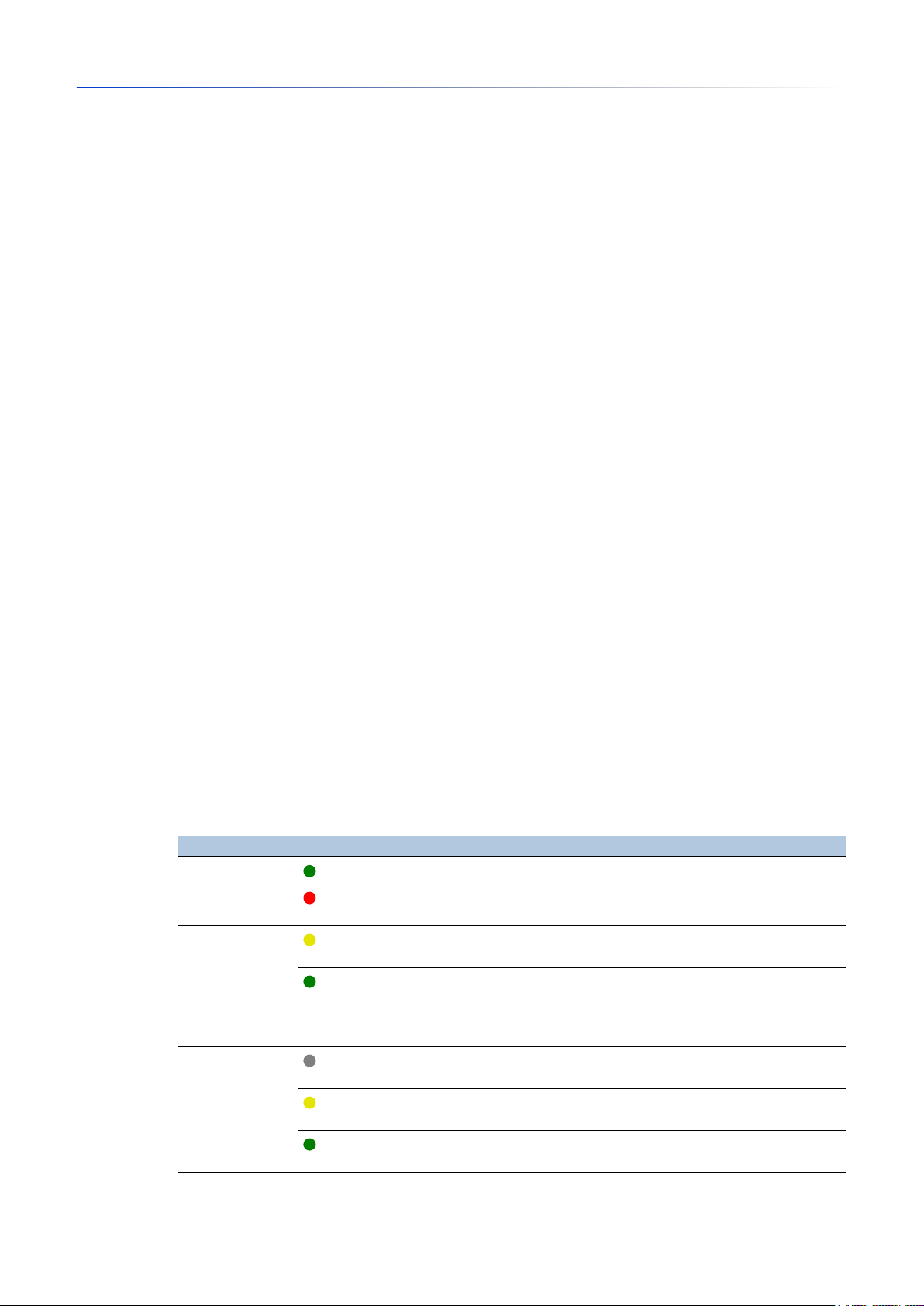
LED status
This frame displays the states of the device status LEDs at the time of the last update. The
“Installation” user manual contains detailed information about the device status LEDs.
Parameters Color Meaning
Status
There is currently no device status alarm. The device status is OK.
There is currently at least one device status alarm. Therefore, see the
Power
Device status
Device variant with 2 power supply units:
frame above.
Only one supply voltage is active.
Device variant with 1 power supply unit:
The supply voltage is active.
Device variant with 2 power supply units:
Both supply voltages are active.
RM
The device is neither operating as a
MRP
ring manager nor as a
DLR
supervisor.
Loss of redundancy reserve.
The device is operating as a
MRP
ring manager.
Redundancy reserve is available.
MRP
The device is operating as a
ring manager.
RM GUI GRS
8.0 09/2019
Release
19
Page 21

Basic Settings
[ Basic Settings > System ]
Parameters Color Meaning
ACA
Port status
This frame displays a simplified view of the ports of the device at the time of the last update.
The icons represent the status of the individual ports. In some situations, the following icons
interfere with one another. When you position the mouse pointer over the appropriate port icon, a
tooltip displays a detailed information about the port state.
Parameters StatusMeaning
No external memory connected.
The external memory is connected, but not ready for operation.
The external memory is connected and ready for operation.
<Port number>
The port is inactive.
The port does not send or receive any data.
The port is inactive.
The cable is connected. Active link.
The port is active.
No cable connected or no active link.
The port is active.
The cable is connected. Connection okay. Active link. Full-duplex mode
The half-duplex mode is enabled.
Verify the settings in the
Basic Settings > Ports
dialog,
Configuration
The port is in a blocking state due to a redundancy function.
The port operates as a router interface.
Buttons
You find the description of the standard buttons in section “Buttons” on page 13.
tab.
20
RM GUI GRS
8.0 09/2019
Release
Page 22

1.2 Modules
[ Basic Settings > Modules ]
The device lets you install or remove the modules during operation (hot-plug).
Basic Settings
[ Basic Settings > Modules]
As long as the
Ethernet module status
column displays the value
configurable
you can configure
the module and save its preferences.
When you replace the module with an identical module, the device applies the settings to the
new module immediately.
When you replace the module with a different type of module, the device applies the factory
settings to the new module.
When you plug a module in an empty slot, the device configures the module with its default
settings. If the slot is inactive, then it remains inactive until you mark the checkbox in the
Active
column. With the port default settings loaded on the module, access to the network is possible.
Install an Ethernet module
Perform the following steps:
Plug the module in the slot.
The device automatically configures the module with the default settings, and detects the
module parameters.
To update the Graphical User Interface, click the button.
The
Ethernet module status
column displays the value
physical
for the installed Ethernet module.
To temporarily save the changes, click the button.
Activate/Deactivate a slot
On a deactivated slot, the device recognizes the installed module and port configuration is possible.
The module establishes no network connections on a deactivated slot.
Perform the following steps:
In the table, highlight the module.
To deactivate the slot and deny network access, unmark the
To activate the slot and allow network access, mark the
Active
To temporarily save the changes, click the button.
Remove an Ethernet module
Perform the following steps:
Remove the module from the slot.
To update the Graphical User Interface, click the button.
The
Ethernet module status
column displays the value
configurable
In the table, highlight the entry of the removed module.
Click the button and then the
The
Ethernet module status
The
Type
column and some other columns display the value
The marked
Active
checkbox indicates that the slot is still active.
column displays the value
Remove Ethernet module
remove
item.
To temporarily save the changes, click the button.
Active
checkbox.
checkbox.
for the removed module.
for the removed module.
n/a
.
RM GUI GRS
8.0 09/2019
Release
21
Page 23

Basic Settings
[ Basic Settings > Modules]
Table
Ethernet module
Displays the number of the slot to which the entry refers.
Active
Activates/deactivates the slot.
Possible values:
marked
The slot is active. The device recognizes a module installed in this slot.
unmarked
The slot is inactive.
Type
Displays the type of the installed module.
(default setting)
A value of
Description
Specifies a short description of the installed module.
Version
Displays the version of the installed module.
Ports
Displays how many ports are available on the installed module.
Serial number
Displays the serial number of the installed module.
A value of
Ethernet module status
Displays the status of the slot.
n/a
indicates that the slot is empty.
n/a
indicates that the slot is empty.
22
Possible values:
physical
A module is present in the slot.
configurable
The slot is empty and available for configuration.
remove
The slot is empty and deactivated.
fix
The module cannot be removed.
RM GUI GRS
8.0 09/2019
Release
Page 24

Buttons
You find the description of the standard buttons in section “Buttons” on page 13.
Remove Ethernet module
Removes the selected Ethernet module from the table.
Basic Settings
[ Basic Settings > Modules]
RM GUI GRS
8.0 09/2019
Release
23
Page 25

Basic Settings
[ Basic Settings > Network ]
1.3 Network
[ Basic Settings > Network ]
This dialog lets you specify the IP, VLAN and HiDiscovery settings required for the access to the
device management through the network.
Management interface
This frame lets you specify the following settings:
The source from which the device management receives its IP parameters
VLAN in which the device management can be accessed
IP address assignment
Specifies the source from which the device management receives its IP parameters.
VLAN ID
Possible values:
Local
The device uses the IP parameters from the internal memory. You specify the settings for this
in the
IP parameter
BOOTP
frame.
The device receives its IP parameters from a BOOTP or DHCP server.
The server evaluates the MAC address of the device, then assigns the IP parameters.
DHCP
(default setting)
The device receives its IP parameters from a DHCP server.
The server evaluates the MAC address, the DHCP name, or other parameters of the device,
then assigns the IP parameters.
Note: If there is no response from the BOOTP or DHCP server, then the device sets the IP address
to
0.0.0.0
and makes another attempt to obtain a valid IP address.
Specifies the VLAN in which the device management is accessible through the network. The device
management is accessible through ports that are members of this VLAN.
Possible values:
1..4042
The prerequisite is that the VLAN is already configured. See the
(default setting: 1)
Switching > VLAN > Configuration
dialog.
24
When you click the button after changing the value, the
Information
window opens. Select the
port, over which you connect to the device in the future. After clicking the Ok button, the new device
management VLAN settings are assigned to the port.
• After that the port is a member of the VLAN and transmits the data packets without a VLAN tag
(untagged). See the
Switching > VLAN > Configuration
dialog.
• The device assigns the port VLAN ID of the device management VLAN to the port. See the
Switching > VLAN > Port
dialog.
After a short time the device is reachable over the new port in the new device management VLAN.
RM GUI GRS
8.0 09/2019
Release
Page 26

MAC address
Client ID
Basic Settings
[ Basic Settings > Network ]
Displays the MAC address of the device. The device management is accessible via the network
using the MAC address.
BOOTP/DHCP
Displays the DHCP client ID that the device sends to the BOOTP or DHCP server. If the server is
configured accordingly, then it reserves an IP address for this DHCP client ID. Therefore, the device
receives the same IP from the server every time it requests it.
Operation
The DHCP client ID that the device sends is the device name specified in the
the
Basic Settings > System
dialog.
System name
field in
HiDiscovery protocol v1/v2
This frame lets you specify settings for the access to the device using the HiDiscovery protocol.
On a PC, the HiDiscovery software displays the Hirschmann devices that can be accessed in the
network on which the HiDiscovery function is enabled. You can access these devices even if they
have invalid or no IP parameters assigned. The HiDiscovery software lets you assign or change the
IP parameters in the device.
Note: With the HiDiscovery software you access the device only through ports that are members
of the same VLAN as the device management. You specify which VLAN a certain port is assigned
to in the
Switching > VLAN > Configuration
dialog.
Enables/disables the HiDiscovery function in the device.
Possible values:
On
(default setting)
HiDiscovery is enabled.
You can use the HiDiscovery software to access the device from your PC.
Off
HiDiscovery is disabled.
Access
RM GUI GRS
8.0 09/2019
Release
Enables/disables the write access to the device using HiDiscovery.
Possible values:
readWrite
(default setting)
The HiDiscovery software is given write access to the device.
With this setting you can change the IP parameters in the device.
readOnly
The HiDiscovery software is given read-only access to the device.
With this setting you can view the IP parameters in the device.
Recommendation: Change the setting to the value
readOnly
only after putting the device into
operation.
25
Page 27

Basic Settings
[ Basic Settings > Network ]
Signal
Activates/deactivates the flashing of the port LEDs as does the function of the same name in the
HiDiscovery software. The function lets you identify the device in the field.
Possible values:
marked
The flashing of the port LEDs is active.
The port LEDs flash until you disable the function again.
unmarked
The flashing of the port LEDs is inactive.
IP parameter
(default setting)
IP address
Netmask
Gateway address
This frame lets you assign the IP parameters manually. If you have selected the
in the
Management interface
frame,
IP address assignment
option list, then these fields can be edited.
Local
radio button
Specifies the IP address under which the device management can be accessed through the
network.
Possible values:
Valid IPv4 address
Specifies the netmask.
Possible values:
Valid IPv4 netmask
Specifies the IP address of a router through which the device accesses other devices outside its
own network.
26
Possible values:
Valid IPv4 address
Buttons
You find the description of the standard buttons in section “Buttons” on page 13.
RM GUI GRS
8.0 09/2019
Release
Page 28

1.4 Software
[ Basic Settings > Software ]
This dialog lets you update the device software and display information about the device software.
You also have the option to restore a backup of the device software saved in the device.
Basic Settings
[ Basic Settings > Software]
Stored version
Running version
Backup version
Restore
Note: Before updating the device software, follow the version-specific notes in the
Readme
text file.
Version
Displays the version number and creation date of the device software stored in the flash memory.
The device loads the device software during the next restart.
Displays the version number and creation date of the device software that the device loaded during
the last restart and is currently running.
Displays the version number and creation date of the device software saved as a backup in the
flash memory. The device copied this device software into the backup memory during the last
software update or after you clicked the
Restore
button.
Bootcode
URL
Restores the device software saved as a backup. In the process, the device changes the
version
and the
Upon restart, the device loads the
Backup version
of the device software.
Stored version
.
Stored
Displays the version number and creation date of the boot code.
Software update
Alternatively, when the image file is located in the external memory, the device lets you update the
device software by right-clicking in the table.
Specifies the path and the file name of the image file with which you update the device software.
RM GUI GRS
8.0 09/2019
Release
27
Page 29

Basic Settings
[ Basic Settings > Software]
The device gives you the following options for updating the device software:
Software update from the PC
When the file is located on your PC or on a network drive, drag and drop the file in the area.
Alternatively click in the area to select the file.
Software update from an FTP server
When the file is located on an FTP server, specify the URL for the file in the following form:
ftp://<user>:<password>@<IP address>:<port>/<file name>
Software update from a TFTP server
When the file is located on a TFTP server, specify the URL for the file in the following form:
tftp://<IP address>/<path>/<file name>
Software update from an SCP or SFTP server
When the file is located on an SCP or SFTP server, specify the URL for the file in one of the
following forms:
–
scp://
When you click the
User name
–
scp://
or
sftp://<IP address>/<path>/<file name>
Start
button, the device displays the
and
Password
or
sftp://<user>:<password>@<IP address>/<path>/<file name>
, to log on to the server.
Credentials
window. There you enter
Start
File location
Updates the device software.
The device installs the selected file in the flash memory, replacing the previously saved device
software. Upon restart, the device loads the installed device software.
The device copies the existing software into the backup memory.
To remain logged in to the device during the software update, move the mouse pointer
occasionally. Alternatively, specify a sufficiently high value in the
Access > Web
dialog, field
Web interface session timeout [min]
before the software update.
Device Security > Management
Table
Displays the storage location of the device software.
Possible values:
ram
Volatile memory of the device
flash
Non-volatile memory (
usb
NVM
) of the device
External USB memory (ACA21/ACA22)
Index
28
Displays the index of the device software.
RM GUI GRS
8.0 09/2019
Release
Page 30

File name
Firmware
Basic Settings
[ Basic Settings > Software]
For the device software in the flash memory, the index has the following meaning:
1
Upon restart, the device loads this device software.
2
The device copied this device software into the backup area during the last software update.
Displays the device-internal file name of the device software.
Displays the version number and creation date of the device software.
Buttons
You find the description of the standard buttons in section “Buttons” on page 13.
RM GUI GRS
8.0 09/2019
Release
29
Page 31

Basic Settings
[ Basic Settings > Load/Save ]
1.5 Load/Save
[ Basic Settings > Load/Save ]
This dialog lets you save the device settings permanently in a configuration profile.
The device can hold several configuration profiles. When you activate an alternative configuration
profile, you change to other device settings. You have the option of exporting the configuration
profiles to your PC or to a server. You also have the option of importing the configuration profiles
from your PC or from a server to the device.
In the default setting, the device saves the configuration profiles unencrypted. If you enter a
password in the
configuration profiles in an encrypted format.
Unintentional changes to the settings can terminate the connection between your PC and the
device. To keep the device accessible, enable the
changing any settings. If the connection is lost, then the device loads the configuration profile saved
in the non-volatile memory (
Configuration encryption
NVM
) after the specified time.
frame, then the device saves both the current and the future
Undo configuration modifications
function before
External memory
Selected external memory
Displays the type of the external memory.
Possible values:
usb
External USB memory (ACA21/ACA22)
Status
Displays the operating state of the external memory.
Possible values:
notPresent
No external memory connected.
removed
Someone has removed the external memory from the device during operation.
ok
The external memory is connected and ready for operation.
outOfMemory
The memory space is occupied in the external memory.
genericErr
The device has detected an error.
Active
30
Configuration encryption
Displays whether the configuration encryption is active/inactive in the device.
RM GUI GRS
8.0 09/2019
Release
Page 32

Basic Settings
[ Basic Settings > Load/Save ]
Possible values:
marked
The configuration encryption is active.
If the configuration profile is encrypted and the password matches the password stored in the
device, then the device loads a configuration profile from the non-volatile memory (
unmarked
The configuration encryption is inactive.
If the configuration profile is unencrypted, then the device loads a configuration profile from the
non-volatile memory (
NVM
) only.
NVM
).
Set password
If in the
the configuration profile is unencrypted, then the
Basic Settings > External Memory
dialog, the
Security status
Config priority
column has the value
frame in the
Basic Settings > System
first
and
dialog displays an alarm.
In the
Diagnostics > Status Configuration > Security Status
whether the device monitors the
Opens the
Set password
window that helps you to enter the password needed for the configuration
Load unencrypted config from external memory
dialog,
Global
tab,
Monitor
parameter.
column you specify
profile encryption. Encrypting the configuration profiles makes unauthorized access more difficult.
When you are changing an existing password, enter the existing password in the
field. To display the password in plain text instead of ***** (asterisks), mark the
Old password
Display content
checkbox.
In the
New password
field, enter the password.
To display the password in plain text instead of ***** (asterisks), mark the
Display content
checkbox.
Mark the
configuration profile in the non-volatile memory (
Note: If a maximum of 1 configuration profile is stored in the non-volatile memory (
Save configuration afterwards
checkbox to use encryption also for the Selected
NVM
) and in the external memory.
NVM
) of the
device, then use this function only. Before creating additional configuration profiles, decide for or
against permanently activated configuration encryption in the device. Save additional configuration
profiles either unencrypted or encrypted with the same password.
RM GUI GRS
8.0 09/2019
Release
If you are replacing a device with an encrypted configuration profile, for example due to a defect,
then you proceed as follows:
Restart the new device and assign the IP parameters.
Open the
Basic Settings > Load/Save
dialog on the new device.
Encrypt the configuration profile in the new device. See above. Enter the same password you
used in the defective device.
Install the external memory from the defective device in the new device.
Restart the new device.
When you restart the device, the device loads the configuration profile with the settings of the
defective device from the external memory. The device copies the settings into the volatile
memory (
RAM
) and into the non-volatile memory (
NVM
).
31
Page 33

Basic Settings
[ Basic Settings > Load/Save ]
Delete
Opens the
In the
Delete
Old password
To display the password in plain text instead of ***** (asterisks), mark the
checkbox.
Mark the
configuration profile in the non-volatile memory (
Note: If you keep additional encrypted configuration profiles in the memory, then the device helps
prevent you from activating or designating these configuration profiles as "Selected".
Information
NVM in sync with running config
Displays whether the configuration profile in the volatile memory (
configuration profile in the non-volatile memory (
Possible values:
marked
The configuration profiles are the same.
unmarked
The configuration profiles differ.
window which helps you to cancel the configuration encryption in the device.
field, enter the existing password.
Display content
Save configuration afterwards
checkbox to remove the encryption also for the Selected
NVM
) and in the external memory.
RAM
) and the "Selected"
NVM
) are the same.
External memory in sync with NVM
Displays whether the "Selected" configuration profile in the external memory and the "Selected"
configuration profile in the non-volatile memory (
Possible values:
marked
The configuration profiles are the same.
unmarked
The configuration profiles differ.
Possible causes:
– No external memory is connected to the device.
– In the
Basic Settings > External Memory
disabled.
Backup config on a remote server when saving
Operation
Enables/disables the
NVM
) are the same.
dialog, the
Backup config when saving
Backup config on a remote server when saving
function is
function.
32
RM GUI GRS
8.0 09/2019
Release
Page 34

URL
Basic Settings
[ Basic Settings > Load/Save ]
Possible values:
Enabled
The
Backup config on a remote server when saving
When you save the configuration profile in the non-volatile memory (
automatically backs up the configuration profile on the remote server specified in the
Disabled
The
Backup config on a remote server when saving
(default setting)
Specifies path and file name of the backed up configuration profile on the remote server.
Possible values:
Alphanumeric ASCII character string with 0..128 characters
Example:
tftp://192.9.200.1/cfg/config.xml
The device supports the following wildcards:
–
%d
System date in the format
–
%t
System time in the format
–
%i
YYYY-mm-dd
HH_MM_SS
IP address of the device
–
%m
MAC address of the device in the format
–
%p
Product name of the device
function is enabled.
function is disabled.
AA-BB-CC-DD-EE-FF
NVM
), the device
URL
field.
Set credentials
Opens the
Credentials
window which helps you to enter the credentials needed to authenticate on
the remote server.
In the
User name
field, enter the user name.
To display the user name in plain text instead of ***** (asterisks), mark the
checkbox.
Possible values:
– Alphanumeric ASCII character string with 1..32 characters
In the
Password
field, enter the password.
To display the password in plain text instead of ***** (asterisks), mark the
checkbox.
Possible values:
Alphanumeric ASCII character string with 6..64 characters
The following characters are allowed:
a..z
A..Z
0..9
!#$%&'()*+,-./:;<=>?@[\\]^_`{}~
Display content
Display content
RM GUI GRS
8.0 09/2019
Release
33
Page 35

Basic Settings
[ Basic Settings > Load/Save ]
Undo configuration modifications
Operation
Enables/disables the
Undo configuration modifications
continuously checks whether it can still be reached from the IP address of the user’s PC. If the
connection is lost, after a specified time period the device loads the “Selected” configuration profile
from the non-volatile memory (
Possible values:
On
The function is enabled.
– You specify the time period between the interruption of the connection and the loading of the
configuration profile in the field
– When the non-volatile memory (
loads the configuration profile designated as “Selected”.
Off
(default setting)
The function is disabled.
Disable the function again before you close the Graphical User Interface. You thus help prevent
the device from restoring the configuration profile designated as “Selected”.
Note: Before you enable the function, save the settings in the configuration profile. Current
changes, that are saved temporarily, are therefore maintained in the device.
Timeout [s] to recover after connection loss
Specifies the time in seconds after which the device loads the “Selected” configuration profile from
the non-volatile memory (
NVM
). Afterwards, the device can be accessed again.
Timeout [s] to recover after connection loss
NVM
) contains multiple configuration profiles, the device
NVM
) if the connection is lost.
function. Using the function, the device
.
Possible values:
Specify a sufficiently large value. Take into account the time when you are viewing the dialogs of
the Graphical User Interface without changing or updating them.
Watchdog IP address
Displays the IP address of the PC on which you have enabled the function.
Possible values:
IPv4 address (default setting:
Table
Storage type
Displays the storage location of the configuration profile.
30..600
(default setting:
600
)
0.0.0.0
)
34
RM GUI GRS
8.0 09/2019
Release
Page 36

Profile name
Basic Settings
[ Basic Settings > Load/Save ]
Possible values:
RAM
(volatile memory of the device)
In the volatile memory, the device stores the settings for the current operation.
NVM
(non-volatile memory of the device)
When applying the function
the “Selected” configuration profile from the non-volatile memory.
The non-volatile memory provides space for multiple configuration profiles, depending on the
number of settings saved in the configuration profile. The device manages a maximum of 20
configuration profiles in the non-volatile memory.
You can load a configuration profile into the volatile memory (
In the table, highlight the configuration profile.
Click the button and then the
ENVM
(external memory)
In the external memory, the device saves a backup copy of the “Selected” configuration profile.
The prerequisite is that in the
when saving
checkbox.
Undo configuration modifications
Activate
item.
Basic Settings > External Memory
or during a restart, the device loads
RAM
):
dialog you mark the
Backup config
Displays the name of the configuration profile.
Possible values:
running-config
Name of the configuration profile in the volatile memory (
config
Name of the factory setting configuration profile in the non-volatile memory (
User-defined name
The device lets you save a configuration profile with a user-specified name by highlighting an
existing configuration profile in the table, clicking the button and then the
To export the configuration profile as an XML file on your PC, click the link. Then you select the
storage location and specify the file name.
To save the file on a remote server, click the button and then the
Modification date (UTC)
Displays the time (UTC) at which a user last saved the configuration profile.
Selected
Displays whether the configuration profile is designated as “Selected”.
RAM
).
Export...
NVM
Save As..
item.
).
item.
RM GUI GRS
8.0 09/2019
Release
Possible values:
marked
The configuration profile is designated as “Selected”.
– When applying the function
loads the configuration profile into the volatile memory (
Undo configuration modifications
RAM
or during a restart, the device
).
– When you click the button, the device saves the temporarily saved settings in this
configuration profile.
unmarked
Another configuration profile is designated as “Selected”.
To designate another configuration profile as “Selected”, you highlight the desired configuration
profile in the table, click the button and then the
Activate
item.
35
Page 37

Basic Settings
[ Basic Settings > Load/Save ]
Encrypted
Displays whether the configuration profile is encrypted.
Possible values:
marked
The configuration profile is encrypted.
unmarked
The configuration profile is unencrypted.
You activate/deactivate the encryption of the configuration profile in the
frame.
Encryption verified
Displays whether the password of the encrypted configuration profile matches the password stored
in the device.
Possible values:
Software version
Displays the version number of the device software that the device ran while saving the
configuration profile.
Fingerprint
Displays the checksum saved in the configuration profile.
Configuration encryption
marked
The passwords match. The device is able to unencrypt the configuration profile.
unmarked
The passwords are different. The device is unable to unencrypt the configuration profile.
When saving the settings, the device calculates the checksum and inserts it into the configuration
profile.
Fingerprint verified
Displays whether the checksum saved in the configuration profile is valid.
The device calculates the checksum of the configuration profile marked as “Selected” and
compares it with the checksum saved in this configuration profile.
Possible values:
marked
The calculated and the saved checksum match.
The saved settings are consistent.
unmarked
For the configuration profile marked as “Selected” applies:
The calculated and the saved checksum are different.
The configuration profile contains modified settings.
Possible causes:
– The file is damaged.
– The file system in the external memory is inconsistent.
– A user has exported the configuration profile and changed the XML file outside the device.
For the other configuration profiles the device has not calculated the checksum.
36
RM GUI GRS
8.0 09/2019
Release
Page 38

Basic Settings
[ Basic Settings > Load/Save ]
The device verifies the checksum correctly only if the configuration profile has been saved before
as follows:
• on an identical device
• with the same software version, which the device is running
Note: This function identifies changes to the settings in the configuration profile. The function does
not provide protection against operating the device with modified settings.
Buttons
You find the description of the standard buttons in section “Buttons” on page 13.
Save As..
Activate
Removes the configuration profile highlighted in the table from the non-volatile memory (
NVM
) or
from the external memory.
If the configuration profile is designated as "Selected", then the device helps prevent you from
removing the configuration profile.
Copies the configuration profile highlighted in the table and saves it with a user-specified name in
the non-volatile memory (
NVM
). The device designates the new configuration profile as “Selected”.
Note: Before creating additional configuration profiles, decide for or against permanently activated
configuration encryption in the device. Save additional configuration profiles either unencrypted or
encrypted with the same password.
If in the
Basic Settings > External Memory
dialog the checkbox in the
Backup config when saving
column
is marked, then the device designates the configuration profile of the same name in the external
memory as “Selected”.
Loads the settings of the configuration profile highlighted in the table to the volatile memory (
RAM
The device terminates the connection to the Graphical User Interface.
Reload the Graphical User Interface.
Login again.
The device immediately uses the settings of the configuration profile on the fly.
).
RM GUI GRS
8.0 09/2019
Release
Enable the
Undo configuration modifications
function before you activate another configuration profile.
If the connection is lost afterwards, then the device loads the last configuration profile designated
as “Selected” from the non-volatile memory (
NVM
). The device can then be accessed again.
If the configuration encryption is inactive, then the device loads an unencrypted configuration
profile. If the configuration encryption is active and the password matches the password stored in
the device, then the device loads an encrypted configuration profile.
When you activate an older configuration profile, the device takes over the settings of the functions
contained in this software version. The device sets the values of new functions to their default
value.
37
Page 39

Basic Settings
[ Basic Settings > Load/Save ]
Select
Import...
Designates the configuration profile highlighted in the table as “Selected”. In the
the checkbox is then
When applying the function
settings of this configuration profile to the volatile memory (
marked
.
Undo configuration modifications
or during a restart, the device loads the
RAM
).
Selected
column,
If the configuration encryption in the device is disabled, then designate an unencrypted
configuration profile only as “Selected”.
If the configuration encryption in the device is enabled and the password of the configuration
profile matches the password saved in the device, then designate an encrypted configuration
profile only as “Selected”.
Otherwise, the device is unable to load and encrypt the settings in the configuration profile the next
time it restarts. For this case you specify in the
Diagnostics > System > Selftest
dialog whether the
device starts with the default settings or terminates the restart and stops.
Note: You only mark the configuration profiles saved in the non-volatile memory (
If in the
Basic Settings > External Memory
dialog the checkbox in the
Backup config when saving
NVM
).
column
is marked, then the device designates the configuration profile of the same name in the external
memory as “Selected”.
Opens the
The prerequisite is that you have exported the configuration profile using the
using the link in the
In the
Import...
Select source
PC/URL
window to import a configuration profile.
Export...
Profile name
column.
drop-down list, select from where the device imports the configuration profile.
The device imports the configuration profile from the local PC or from a remote server.
External memory
The device imports the configuration profile from the external memory.
When
PC/URL
is selected above, in the
Import profile from PC/URL
frame you specify the
configuration profile file to be imported.
– Import from the PC
When the file is located on your PC or on a network drive, drag and drop the file in the
area. Alternatively click in the area to select the file.
– Import from an FTP server
When the file is located on an FTP server, specify the URL for the file in the following form:
ftp://<user>:<password>@<IP address>:<port>/<file name>
– Import from a TFTP server
When the file is located on a TFTP server, specify the URL for the file in the following form:
tftp://<IP address>/<path>/<file name>
– Import from an SCP or SFTP server
When the file is located on an SCP or SFTP server, specify the URL for the file in one of the
following forms:
scp://
When you click the
User name
scp://
or
sftp://<IP address>/<path>/<file name>
Start
button, the device displays the
and
Password
or
sftp://<user>:<password>@<IP address>/<path>/<file name>
, to log on to the server.
Credentials
window. There you enter
button or
38
RM GUI GRS
8.0 09/2019
Release
Page 40

Basic Settings
[ Basic Settings > Load/Save ]
When
External memory
is selected above, in the
Import profile from external memory
frame you
specify the configuration profile file to be imported.
In the
In the
In the
Profile name
Destination
Profile name
drop-down list, select the name of the configuration profile to be imported.
frame you specify where the device saves the imported configuration profile.
field you specify the name under which the device saves the configuration
profile.
In the
Storage type
prerequisite is that in the
RAM
The device saves the configuration profile in the volatile memory (
replaces the
field you specify the storage location for the configuration profile. The
Select source
running-config
drop-down list you have selected the value
RAM
) of the device. This
PC/URL
, the device uses the settings of the imported configuration
.
profile immediately. The device terminates the connection to the Graphical User Interface.
Reload the Graphical User Interface. Login again.
NVM
The device saves the configuration profile in the non-volatile memory (
NVM
) of the device.
When you import a configuration profile, the device takes over the settings as follows:
• If the configuration profile was exported on the same device or on an identically equipped device
of the same type, then:
The device takes over the settings completely.
If the device uses modules, then also read the help text of the
Basic Settings > Modules
dialog.
• If the configuration profile was exported on an other device, then:
The device takes over the settings which it can interpret based on its hardware equipment and
software level.
The remaining settings the device takes over from its
running-config
configuration profile.
Export...
Regarding configuration profile encryption, also read the help text of the
Configuration encryption
frame. The device imports a configuration profile under the following conditions:
• The configuration encryption of the device is inactive. The configuration profile is unencrypted.
• The configuration encryption of the device is active. The configuration profile is encrypted with
the same password that the device currently uses.
Exports the configuration profile highlighted in the table and saves it as an XML file on a remote
server.
To save the file on your PC, click the link in the
Profile name
column to select the storage location
and specify the file name.
The device gives you the following options for exporting a configuration profile:
Export to an FTP server
To save the file on an FTP server, specify the URL for the file in the following form:
ftp://<user>:<password>@<IP address>:<port>/<file name>
Export to a TFTP server
To save the file on a TFTP server, specify the URL for the file in the following form:
tftp://<IP address>/<path>/<file name>
Export to an SCP or SFTP server
To save the file on an SCP or SFTP server, specify the URL for the file in one of the following
forms:
–
scp://
When you click the Ok button, the device displays the
User name
–
scp://
or
sftp://<IP address>/<path>/<file name>
Credentials
and
Password
or
sftp://<user>:<password>@<IP address>/<path>/<file name>
, to log on to the server.
window. There you enter
RM GUI GRS
8.0 09/2019
Release
39
Page 41

Basic Settings
[ Basic Settings > Load/Save ]
Load running-config as script
Imports a script file which modifies the current
The device gives you the following options to import a script file:
Import from the PC
When the file is located on your PC or on a network drive, drag and drop the file in the area.
Alternatively click in the area to select the file.
Import from an FTP server
When the file is located on an FTP server, specify the URL for the file in the following form:
ftp://<user>:<password>@<IP address>:<port>/<file name>
Import from a TFTP server
When the file is located on a TFTP server, specify the URL for the file in the following form:
tftp://<IP address>/<path>/<file name>
Import from an SCP or SFTP server
When the file is located on an SCP or SFTP server, specify the URL for the file in one of the
following forms:
scp://
Save running-config as script
Saves the
backup your current device settings or to use them on various devices.
running config
or
sftp://<IP address>/<path>/<file name>
running config
configuration profile as a script file on the local PC. This lets you
configuration profile.
Back to factory...
Back to default
Resets the settings in the device to the default values.
The device deletes the saved configuration profiles from the volatile memory (
non-volatile memory (
NVM
).
RAM
) and from the
The device deletes the HTTPS certificate used by the web server in the device.
The device deletes the RSA key (Host Key) used by the SSH server in the device.
When an external memory is connected, the device deletes the configuration profiles saved in
the external memory.
After a brief period, the device reboots and loads the default values.
Deletes the current operating (
running config
) settings from the volatile memory (
RAM
) .
40
RM GUI GRS
8.0 09/2019
Release
Page 42

1.6 External Memory
[ Basic Settings > External Memory ]
This dialog lets you activate functions that the device automatically executes in combination with
the external memory. The dialog also displays the operating state and identifying characteristics of
the external memory.
Configuration
USB mode
Specifies the mode of communication between the device and the external memory. To activate
the changes to this field, save the settings permanently and restart the device.
Possible values:
normal
Device and external memory communicate in the high-speed mode (480 Mbit/s).
compatibility
Device and external memory communicate in the full-speed mode (12 Mbit/s).
(USB 2.0 mode)
(USB 1.1 compatibility mode)
Basic Settings
[ Basic Settings > External Memory ]
Note: The external memory ACA21 operates only in the USB 1.1 compatibility mode. If you use this
external memory, then specify the value
Information
Current USB mode
Displays the mode the device currently uses for the communication with the external memory.
Possible values:
Table
normal
compatibility
(USB 2.0 mode)
.
Device and external memory communicate in the high-speed mode (480 Mbit/s).
compatibility
(USB 1.1 compatibility mode)
Device and external memory communicate in the full-speed mode (12 Mbit/s).
Type
RM GUI GRS
8.0 09/2019
Release
Displays the type of the external memory.
Possible values:
usb
External USB memory (ACA21/ACA22)
41
Page 43

Basic Settings
[ Basic Settings > External Memory ]
Status
Displays the operating state of the external memory.
Possible values:
notPresent
No external memory connected.
removed
Someone has removed the external memory from the device during operation.
ok
The external memory is connected and ready for operation.
outOfMemory
The memory space is occupied in the external memory.
genericErr
The device has detected an error.
Writable
Displays whether the device has write access to the external memory.
Possible values:
Software auto update
Activates/deactivates the automatic device software update during the restart.
Possible values:
SSH key auto upload
Activates/deactivates the loading of the RSA key from an external memory upon restart.
marked
The device has write access to the external memory.
unmarked
The device has read-only access to the external memory. Possibly the write protection is
activated in the external memory.
marked
(default setting)
The automatic device software update during the restart is activated. The device updates the
device software when the following files are located in the external memory:
– the image file of the device software
– a text file "startup.txt" with the content
autoUpdate=<image_file_name>.bin
unmarked
The automatic device software update during the restart is deactivated.
42
RM GUI GRS
8.0 09/2019
Release
Page 44

Basic Settings
[ Basic Settings > External Memory ]
Possible values:
marked
The loading of the RSA key is activated.
During a restart, the device loads the RSA key from the external memory when the following
files are located in the external memory:
– SSH RSA key file
– a text file “startup.txt” with the content
The device displays messages on the system console of the serial interface.
unmarked
The loading of the RSA key is deactivated.
(default setting)
autoUpdateRSA=<filename_of_the_SSH_RSA_key>
Config priority
Note: When loading the RSA key from the external memory (
existing keys in the non-volatile memory (
NVM
).
ENVM
), the device overwrites the
Specifies the memory from which the device loads the configuration profile upon reboot.
Possible values:
disable
The device loads the configuration profile from the non-volatile memory (
first
NVM
).
The device loads the configuration profile from the external memory.
When the device does not find a configuration profile in the external memory, it loads the
configuration profile from the non-volatile memory (
Note: When loading the configuration profile from the external memory (
NVM
).
ENVM
), the device
overwrites the settings of the Selected configuration profile in the non-volatile memory (
If the
Config priority
the
Security status
In the
Diagnostics > Status Configuration > Security Status
whether the device monitors the
column has the value
frame in the
Basic Settings > System
Load unencrypted config from external memory
first
and the configuration profile is unencrypted, then
dialog displays an alarm.
dialog,
Global
tab,
Monitor
column you specify
parameter.
NVM
).
Backup config when saving
Activates/deactivates creating a copy of the configuration profile in the external memory.
Possible values:
marked
Creating a copy is activated. When you click in the
button, the device generates a copy of the configuration profile on the active external memory.
unmarked
Creating a copy is deactivated. The device does not generate a copy of the configuration profile.
Manufacturer ID
Displays the name of the memory manufacturer.
Revision
Displays the revision number specified by the memory manufacturer.
RM GUI GRS
8.0 09/2019
Release
(default setting)
Basic Settings > Load/Save
dialog the
Save
43
Page 45

Basic Settings
[ Basic Settings > External Memory ]
Version
Displays the version number specified by the memory manufacturer.
Name
Displays the product name specified by the memory manufacturer.
Serial number
Displays the serial number specified by the memory manufacturer.
Buttons
You find the description of the standard buttons in section “Buttons” on page 13.
44
RM GUI GRS
8.0 09/2019
Release
Page 46

1.7 Port
[ Basic Settings > Port]
This dialog lets you specify settings for the individual ports. The dialog also displays the operating
mode, connection status, bit rate and duplex mode for every port.
The dialog contains the following tabs:
[Configuration]
[Statistics]
[Utilization]
[Configuration]
Table
Basic Settings
[ Basic Settings > Port]
Port
Name
Port on
Displays the port number.
Name of the port.
Possible values:
Alphanumeric ASCII character string with 0..64 characters
The following characters are allowed:
–
<space>
–
0..9
–
a..z
–
A..Z
–
!#$%&'()*+,-./:;<=>?@[\\]^_`{}~
Activates/deactivates the port.
Possible values:
marked
(default setting)
The port is active.
unmarked
The port is inactive. The port does not send or receive any data.
State
RM GUI GRS
8.0 09/2019
Release
Displays whether the port is currently physically enabled or disabled.
45
Page 47

Basic Settings
[ Basic Settings > Port]
Possible values:
marked
The port is physically enabled.
unmarked
The port is physically disabled.
When the
You specify the settings of the
dialog.
Power state (port off)
Specifies, whether the port is physically switched on or off when you deactivate the port with the
Port on
Possible values:
marked
The port remains physically enabled. A connected device receives an active link.
unmarked
The port is physically disabled.
Port on
function.
function is active, the
(default setting)
Auto-Disable
Auto-Disable
function has disabled the port.
function in the
Diagnostics > Ports > Auto-Disable
Auto power down
Specifies how the port behaves when no cable is connected.
Possible values:
no-power-save
The port remains activated.
auto-power-down
The port changes to the energy-saving mode.
unsupported
The port does not support this function and remains activated.
Automatic configuration
Activates/deactivates the automatic selection of the operating mode for the port.
Possible values:
marked
The automatic selection of the operating mode is active.
The port negotiates the operating mode independently using autonegotiation and detects the
devices connected to the TP port automatically (Auto Cable Crossing). This setting has priority
over the manual setting of the port.
Elapse several seconds until the port has set the operating mode.
unmarked
The automatic selection of the operating mode is inactive.
The port operates with the values you specify in the
Manual cable crossing (Auto. conf. off)
Grayed-out display
No automatic selection of the operating mode.
(default setting)
(default setting)
column.
Manual configuration
column and in the
Manual configuration
Specifies the operating mode of the ports when the
46
Automatic configuration
function is disabled.
RM GUI GRS
8.0 09/2019
Release
Page 48

Possible values:
Note: The operating modes of the port actually available depend on the device configuration and
the media module used.
Link/Current settings
Displays the operating mode which the port currently uses.
Basic Settings
[ Basic Settings > Port]
10 Mbit/s HDX
Half duplex connection
10 Mbit/s FDX
Full duplex connection
100 Mbit/s HDX
Half duplex connection
100 Mbit/s FDX
Full duplex connection
1000 Mbit/s FDX
Full duplex connection
Possible values:
–
No cable connected, no link.
10 Mbit/s HDX
Half duplex connection
10 Mbit/s FDX
Full duplex connection
100 Mbit/s HDX
Half duplex connection
100 Mbit/s FDX
Full duplex connection
1000 Mbit/s FDX
Full duplex connection
Note: The operating modes of the port actually available depend on the device configuration and
the media module used.
Manual cable crossing (Auto. conf. off)
Specifies the devices connected to a TP port.
The prerequisite is that the
Automatic configuration
function is disabled.
RM GUI GRS
8.0 09/2019
Release
Possible values:
mdi
The device interchanges the send- and receive-line pairs on the port.
mdix
(default setting on TP ports)
The device helps prevent the interchange of the send- and receive-line pairs on the port.
auto-mdix
The device detects the send and receive line pairs of the connected device and automatically
adapts to them.
Example: When you connect an end device with a crossed cable, the device automatically
resets the port from
unsupported
mdix
to
mdi
.
(default setting on optical ports or TP-SFP ports)
The port does not support this function.
47
Page 49

Basic Settings
[ Basic Settings > Port]
Flow control
Activates/deactivates the flow control on the port.
Possible values:
marked
The Flow control on the port is active.
The sending and evaluating of pause packets (full-duplex operation) or collisions (half-duplex
operation) is activated on the port.
To enable the flow control in the device, also activate the
Activate the flow control also on the port of the device that is connected to this port.
On an uplink port, activating the flow control can possibly cause undesired sending breaks in
the higher-level network segment (“wandering backpressure”).
unmarked
The Flow control on the port is inactive.
If you are using a redundancy function, then you deactivate the flow control on the participating
ports. If the flow control and the redundancy function are active at the same time, it is possible that
the redundancy function operates differently than intended.
(default setting)
Switching > Global
dialog.
Flow control
function in the
Send trap (Link up/down)
Activates/deactivates the sending of SNMP traps when the device detects changes in the link up/
down status for this port.
Possible values:
marked
The sending of SNMP traps is active.
When the device detects a link up/down status change, the device sends an SNMP trap.
unmarked
The sending of SNMP traps is inactive.
The prerequisite for sending SNMP traps is that you enable the function in the
Configuration > Alarms (Traps)
Signal
Activates/deactivates the port LED flashing. This function lets you identify the port in the field.
Possible values:
marked
The flashing of the port LED is active.
The port LED flashes until you disable the function again.
unmarked
The flashing of the port LED is inactive.
(default setting)
Diagnostics > Status
dialog and specify at least 1 trap destination.
(default setting)
Link monitoring
48
Activates/deactivates the
Use the
Link monitoring
function for end devices that do not support Far End Fault Indication (FEFI)
on optical links.
Link monitoring
function on the interface.
RM GUI GRS
8.0 09/2019
Release
Page 50

Possible values:
Buttons
You find the description of the standard buttons in section “Buttons” on page 13.
Clear port statistics
Resets the counter for the port statistics to 0.
Basic Settings
[ Basic Settings > Port]
marked
The
Link monitoring
If the device recognizes an established link, then the port LED illuminates. If the device
recognizes that a link has been lost, then the port LED extinguishes.
unmarked
The
Link monitoring
function is active.
(default setting)
function is inactive.
[Statistics]
This tab displays the following overview per port:
Number of data packets/bytes received in the device
–
Received packets
–
Received octets
–
Received unicast packets
–
Received multicast packets
–
Received broadcast packets
Number of data packets/bytes sent from the device
–
Transmitted packets
–
Transmitted octets
–
Transmitted unicast packets
–
Transmitted multicast packets
–
Transmitted broadcast packets
Number of errors detected by the device
–
Received fragments
–
Detected CRC errors
–
Detected collisions
Number of data packets per size category received on the device
–
Packets 64 bytes
–
Packets 65 to 127 bytes
–
Packets 128 to 255 bytes
–
Packets 256 to 511 bytes
–
Packets 512 to 1023 bytes
–
Packets 1024 to 1518 bytes
Number of data packets discarded by the device
–
Received discards
–
Transmitted discards
RM GUI GRS
8.0 09/2019
Release
To sort the table by a specific criterion click the header of the corresponding row.
For example, to sort the table based on the number of received bytes in ascending order, click the
header of the
Received octets
column once. To sort in descending order, click the header again.
49
Page 51

Basic Settings
[ Basic Settings > Port]
To reset the counter for the port statistics in the table to 0, proceed as follows:
In the
or
In the
Buttons
You find the description of the standard buttons in section “Buttons” on page 13.
Clear port statistics
Resets the counter for the port statistics to 0.
[Utilization]
Basic Settings > Port
dialog, click the button and then the
Basic Settings > Restart
dialog, click the
Clear port statistics
Clear port statistics
button.
item.
This tab displays the utilization (network load) for the individual ports.
Table
Port
Displays the port number.
Utilization [%]
Displays the current utilization in percent in relation to the time interval specified in the
interval [s]
The utilization is the relationship of the received data quantity to the maximum possible data
quantity at the currently configured data rate.
Lower threshold [%]
Specifies a lower threshold for the utilization. If the utilization of the port falls below this value, then
the
Possible values:
column.
Alarm
column displays an alarm.
0.00..100.00
(default setting:
0.00
Control
)
The value 0 deactivates the lower threshold.
Upper threshold [%]
Specifies an upper threshold for the utilization. If the utilization of the port exceeds this value, then
the
Possible values:
The value 0 deactivates the upper threshold.
50
Alarm
column displays an alarm.
0.00..100.00
(default setting:
0.00
)
RM GUI GRS
8.0 09/2019
Release
Page 52

Control interval [s]
Alarm
Specifies the interval in seconds.
Possible values:
1..3600
(default setting: 30)
Displays the utilization alarm status.
Possible values:
marked
The utilization of the port is below the value specified in the
the value specified in the
unmarked
Upper threshold [%]
column. The device sends an SNMP trap.
The utilization of the port is above the value specified in the
the value specified in the
Upper threshold [%]
column.
Lower threshold [%]
Lower threshold [%]
The prerequisite for sending SNMP traps is that you enable the function in the
Status Configuration
> Alarms (Traps)
dialog and specify at least 1 trap destination.
Basic Settings
[ Basic Settings > Port]
column or above
column and below
Diagnostics >
Buttons
You find the description of the standard buttons in section “Buttons” on page 13.
Clear port statistics
Resets the counter for the port statistics to 0.
RM GUI GRS
8.0 09/2019
Release
51
Page 53

Basic Settings
[ Basic Settings > Restart ]
1.8 Restart
[ Basic Settings > Restart]
This dialog lets you restart the device, reset port counters and address tables, and delete log files.
Restart
Restart in
Displays the remaining time until the device restarts.
To update the display of the remaining time, click the button.
Cancel
Aborts a delayed restart.
Cold start...
Opens the
If the configuration profile in the volatile memory (
the non-volatile memory (
To permanently save the changes, click the
To discard the changes, click No in the
In the
Restart
Restart in
dialog to initiate an immediate or delayed restart of the device.
RAM
) and the "Selected" configuration profile in
NVM
) differ, then the device displays the
Yes
button in the
Warning
dialog.
Warning
Warning
dialog.
dialog.
field you specify the delay time for the delayed restart.
Possible values:
–
00:00:00..596:31:23
(default setting:
00:00:00
)
When the delay time elapsed, the device restarts and goes through the following phases:
If you activate the function in the
Diagnostics > System > Selftest
dialog, then the device performs
a RAM test.
The device starts the device software that the
Stored version
field displays in the
Basic Settings >
Software dialog.
The device loads the settings from the "Selected" configuration profile. See the
Basic Settings >
Load/Save dialog.
Note: During the restart, the device does not transfer any data. During this time, the device cannot
be accessed by the Graphical User Interface or other management systems.
Buttons
You find the description of the standard buttons in section “Buttons” on page 13.
Reset MAC address table
Removes the MAC addresses from the forwarding table that have in the
Addresses
52
dialog the value
learned
in the
Status
column.
Switching > Filter for MAC
RM GUI GRS
8.0 09/2019
Release
Page 54

Reset ARP table
Basic Settings
[ Basic Settings > Restart ]
Removes the dynamically set up addresses from the ARP table.
See the
Clear port statistics
Resets the counter for the port statistics to 0.
See the
Reset IGMP snooping data
Removes the IGMP Snooping entries and resets the counter in the
See the
Delete log file
Removes the logged events from the log file.
See the
Delete persistent log file
Removes the log files from the external memory.
Diagnostics > System > ARP
Basic Settings > Port
dialog,
dialog.
Statistics
Switching > IGMP Snooping > Global
Diagnostics > Report > System Log
tab.
dialog.
dialog.
Information
frame to 0.
See the
Diagnostics > Report > Persistent Logging
dialog.
RM GUI GRS
8.0 09/2019
Release
53
Page 55

Time
[ Time > Basic Settings]
2 Time
The menu contains the following dialogs:
Basic Settings
SNTP
2.1 Basic Settings
[ Time > Basic Settings ]
The device is equipped with a buffered hardware clock. This clock maintains the correct time if the
power supply fails or you disconnect the device from the power supply. After the device is started,
the current time is available to you, for example for log entries.
The hardware clock bridges a power supply downtime of 3 hours. The prerequisite is that the power
supply of the device has been connected continually for at least 5 minutes beforehand.
In this dialog, you specify time-related settings independently of the time synchronization protocol
specified.
The dialog contains the following tabs:
[Global]
[Daylight saving time]
[Global]
In this tab, you specify the system time in the device and the time zone.
Configuration
System time (UTC)
Displays the current date and time with reference to Universal Time Coordinated (UTC).
Set time from PC
The device uses the time on the PC as the system time.
System time
Time source
54
Displays the current date and time with reference to the local time:
+
Local offset [min] +Daylight saving time
System time
=
System time (UTC)
Displays the time source from which the device gets the time information.
The device automatically selects the available time source with the greatest accuracy.
Release
RM GUI GRS
8.0 09/2019
Page 56

Local offset [min]
Possible values:
local
System clock of the device.
sntp
The
SNTP
client is activated and the device is synchronized by an
[ Time > Basic Settings]
SNTP
server.
Time
Specifies the difference between the local time and
System time
Possible values:
-780..840
Buttons
You find the description of the standard buttons in section “Buttons” on page 13.
[Daylight saving time]
In this tab, you activate the automatic daylight saving time function. You specify the beginning and
the end of summertime using a pre-defined profile, or you specify these settings individually. During
summertime, the device puts the local time forward by 1 hour.
Operation
−
System time (UTC)
(default setting: 60)
System time (UTC)
in minutes:
Local offset [min]
=
Daylight saving time
Enables/disables the
Possible values:
The times at which the device changes between summertime and wintertime are specified in the
Summertime begin
Profile...
Displays the
summertime. This profile overwrites the settings in the
frames.
Daylight saving time
mode.
On
The
Daylight saving time
mode is enabled.
The device automatically changes between summertime and wintertime.
Off
(default setting)
The
Daylight saving time
and
Profile...
mode is disabled.
Summertime end
frames.
dialog. There you select a pre-defined profile for the beginning and the end of
Summertime begin
and
Summertime end
RM GUI GRS
8.0 09/2019
Release
55
Page 57

Time
[ Time > Basic Settings]
Summertime begin
In the first 3 fields you specify the day for the beginning of summertime, and in the last field the time.
Week
Day
When the time in the
System time
field reaches the value entered here, the device switches to
summertime.
Specifies the week in the current month.
Possible values:
none
first
second
third
fourth
last
(default setting)
Specifies the day of the week.
Possible values:
none
Sunday
Monday
Tuesday
Wednesday
Thursday
Friday
Saturday
(default setting)
Month
56
Specifies the month.
Possible values:
none
January
February
March
April
May
June
July
August
September
October
November
December
(default setting)
RM GUI GRS
8.0 09/2019
Release
Page 58

System time
Time
[ Time > Basic Settings]
Specifies the time.
Possible values:
<HH:MM>
Summertime end
In the first 3 fields you specify the day for the end of summertime, and in the last field the time.
(default setting:
00:00
)
Week
Day
When the time in the
System time
field reaches the value entered here, the device switches to
wintertime.
Specifies the week in the current month.
Possible values:
none
first
second
third
fourth
last
(default setting)
Specifies the day of the week.
Possible values:
none
Sunday
Monday
Tuesday
Wednesday
Thursday
Friday
Saturday
(default setting)
Month
RM GUI GRS
8.0 09/2019
Release
Specifies the month.
Possible values:
none
January
February
March
April
(default setting)
57
Page 59

Time
[ Time > SNTP]
System time
May
June
July
August
September
October
November
December
Specifies the time.
Possible values:
<HH:MM>
(default setting:
00:00
)
Buttons
You find the description of the standard buttons in section “Buttons” on page 13.
2.2 SNTP
[ Time > SNTP]
The Simple Network Time Protocol (SNTP) is a procedure described in the RFC 4330 for time
synchronization in the network.
The device lets you synchronize the system time in the device as an
server, the device makes the time information available to other devices.
The menu contains the following dialogs:
SNTP Client
SNTP Server
SNTP
client. As the
SNTP
58
RM GUI GRS
8.0 09/2019
Release
Page 60

2.2.1 SNTP Client
[ Time > SNTP > Client]
Time
[ Time > SNTP > Client]
Operation
In this dialog, you specify the settings with which the device operates as an
As an
SNTP
client the device obtains the time information from both
SNTP
servers and
and synchronizes the local clock with the time of the time server.
Operation
Enables/disables the
SNTP Client
function of the device.
Possible values:
On
The
SNTP Client
The device operates as an
Off
(default setting)
The
SNTP Client
function is enabled.
SNTP
client.
function is disabled.
Configuration
SNTP
client.
NTP
servers
Mode
Specifies whether the device actively requests the time information from an
configured in the network (Unicast mode) or passively waits for the time information from a random
SNTP
server (Broadcast mode).
Possible values:
unicast
The device takes the time information only from the configured
Unicast requests to the
broadcast
The device obtains the time information from one or more
evaluates the Broadcasts or Multicasts only from these servers.
Request interval [s]
Specifies the interval in seconds at which the device requests time information from the
server.
Possible values:
5..3600
Broadcast recv timeout [s]
(default setting)
SNTP
(default setting: 30)
SNTP
server and evaluates its responses.
SNTP
or
SNTP
server known and
server. The device sends
NTP
servers. The device
SNTP
RM GUI GRS
8.0 09/2019
Release
Specifies the time in seconds a client in broadcast client mode waits before changing the value in
the field from
syncToRemoteServer
to
notSynchronized
when the client receives no broadcast
packets.
59
Page 61

Time
[ Time > SNTP > Client]
Possible values:
128..2048
Disable client after successful sync
(default setting:
320
)
State
Activates/deactivates the disabling of the
synchronized the time.
Possible values:
marked
The disabling of the
The device deactivates the
unmarked
(default setting)
The disabling of the
The
SNTP
client remains active after successful time synchronization.
SNTP
client is active.
SNTP
SNTP
client is inactive.
client after successful time synchronization.
State
Displays the status of the
SNTP
client.
Possible values:
disabled
The
SNTP
client is disabled.
notSynchronized
The
SNTP
client is not synchronized with any
synchronizedToRemoteServer
The
SNTP
client is synchronized with an
SNTP
client after the device has successfully
SNTP
or
NTP
server.
SNTP
or
NTP
server.
Index
60
Table
In the table you specify the settings for up to 4
SNTP
servers.
Displays the index number to which the table entry relates.
Possible values:
1..4
The device automatically assigns this number.
When you delete a table entry, this leaves a gap in the numbering. When you create a new table
entry, the device fills the first gap.
RM GUI GRS
8.0 09/2019
Release
Page 62

Time
[ Time > SNTP > Client]
Name
Address
After starting, the device sends requests to the
SNTP
server configured in the first table entry. When
the server does not reply, the device sends its requests to the
table entry.
If none of the configured
SNTP
servers responds in the meantime, then the
its synchronization. The device cyclically sends requests to each
a valid time. The device synchronizes itself with this
SNTP
server, even if the other servers can be
reached again later.
Specifies the name of the
SNTP
server.
Possible values:
Alphanumeric ASCII character string with 1..32 characters
Specifies the IP address of the
SNTP
server.
Possible values:
Valid IPv4 address (default setting:
0.0.0.0
)
SNTP
server configured in the next
SNTP
client interrupts
SNTP
server until a server delivers
Destination UDP port
Specifies the UDP Port on which the
Possible values:
Status
Displays the connection status between the
Possible values:
SNTP
server expects the time information.
1..65535
Exception: Port
(default setting:
2222
is reserved for internal functions.
123
)
SNTP
client and the
SNTP
server.
success
The device has successfully synchronized the time with the
SNTP
server.
badDateEncoded
The time information received contains protocol errors - synchronization failed.
other
– The value
0.0.0.0
is entered for the IP address of the
SNTP
server - synchronization failed.
or
– The
SNTP
client is using a different
SNTP
server.
requestTimedOut
The device has not received a reply from the
SNTP
server - synchronization failed.
serverKissOfDeath
The
SNTP
server is overloaded. The device is requested to synchronize itself with another
server. When no other
setting in the
Request interval [s]
SNTP
server is available, the device checks at intervals longer than the
field, if the server is still overloaded.
SNTP
RM GUI GRS
8.0 09/2019
Release
61
Page 63

Time
[ Time > SNTP > Client]
serverUnsychronized
The
synchronization failed.
versionNotSupported
The
synchronization failed.
Active
SNTP
server is not synchronized with either a local or an external reference time source -
SNTP
versions on the client and the server are incompatible with each other -
Activates/deactivates the connection to the
SNTP
server.
Possible values:
marked
The connection to the
The
SNTP
client has access to the
unmarked
(default setting)
The connection to the
The
SNTP
client has no access to the
SNTP
server is activated.
SNTP
SNTP
server is deactivated.
server.
SNTP
server.
Buttons
You find the description of the standard buttons in section “Buttons” on page 13.
62
RM GUI GRS
8.0 09/2019
Release
Page 64

2.2.2 SNTP Server
[ Time > SNTP > Server]
Time
[ Time > SNTP > Server]
Operation
In this dialog, you specify the settings with which the device operates as an
The
SNTP
server provides the Universal Time Coordinated (UTC) without considering local time
differences.
If the setting is appropriate, then the
mode, the
SNTP
server automatically sends broadcast messages or multicast messages according
SNTP
server operates in the broadcast mode. In broadcast
to the broadcast send interval.
Operation
Enables/disables the
SNTP Server
function of the device.
Possible values:
On
The
SNTP Server
The device operates as an
Off
(default setting)
The
SNTP Server
function is enabled.
SNTP
server.
function is disabled.
SNTP
server.
Note the setting in the
Configuration
UDP port
Specifies the number of the UDP port on which the
from other clients.
Possible values:
1..65535
Exception: Port
Broadcast admin mode
Activates/deactivates the Broadcast mode.
marked
The
packets in Broadcast mode as Broadcasts or Multicasts.
unmarked
The
Disable server at local time source
(default setting:
2222
is reserved for internal functions.
SNTP
server replies to requests from
123
(default setting)
SNTP
server replies to requests from
checkbox in the
SNTP
server of the device receives requests
Configuration
frame.
)
SNTP
clients in Unicast mode and also sends
SNTP
clients in the Unicast mode.
SNTP
Broadcast destination address
Specifies the IP address to which the
Broadcast mode.
RM GUI GRS
8.0 09/2019
Release
SNTP
server of the device sends the
SNTP
packets in
63
Page 65

Time
[ Time > SNTP > Server]
Possible values:
Valid IPv4 address (default setting:
Broadcast and Multicast addresses are permitted.
Broadcast UDP port
0.0.0.0
)
Specifies the number of the UDP port on which the
Broadcast mode.
Possible values:
1..65535
Exception: Port
Broadcast VLAN ID
Specifies the ID of the VLAN in which the
Broadcast mode.
Possible values:
0
The
management is possible. See the
1..4042
Broadcast send interval [s]
Specifies the time interval at which the
Possible values:
64..1024
(default setting:
SNTP
server sends the
(default setting: 1)
(default setting:
123
)
2222
is reserved for internal functions.
SNTP
SNTP
packets in the same VLAN in which the access to the device
Basic Settings > Network
SNTP
server of the device sends
128
)
SNTP
server sends the
SNTP
server of the device sends the
dialog.
SNTP
packets in
SNTP
packets in
broadcast packets.
Disable server at local time source
Activates/deactivates the disabling of the
clock.
Possible values:
marked
The disabling of the
If the device is synchronized to the local clock, then the device disables the
SNTP
server continues to reply to requests from
server informs the clients that it is synchronized locally.
unmarked
The disabling of the
If the device is synchronized to the local clock, then the
State
State
Displays the state of the
SNTP
server is active.
(default setting)
SNTP
server is inactive.
SNTP
server.
SNTP
server when the device is synchronized to the local
SNTP
server. The
SNTP
clients. In the
SNTP
server remains active.
SNTP
packet, the
SNTP
64
RM GUI GRS
8.0 09/2019
Release
Page 66

[ Time > SNTP > Server]
Possible values:
disabled
The
SNTP
server is disabled.
notSynchronized
The
SNTP
server is not synchronized with either a local or an external reference time source.
syncToLocal
The
SNTP
server is synchronized with the hardware clock of the device.
syncToRefclock
The
SNTP
server is synchronized with an external reference time source.
syncToRemoteServer
The
SNTP
server is synchronized with an
SNTP
server that is higher than the device in a
cascade.
Buttons
You find the description of the standard buttons in section “Buttons” on page 13.
Time
RM GUI GRS
8.0 09/2019
Release
65
Page 67

Device Security
[ Device Security > User Management ]
3 Device Security
The menu contains the following dialogs:
User Management
Authentication List
Management Access
Pre-login Banner
3.1 User Management
[ Device Security > User Management ]
If users log in with valid login data, then the device lets them have access to its device
management.
Login attempts
In this dialog you manage the users of the local user management. You also specify the following
settings here:
Settings for the login
Settings for saving the passwords
Specify policy for valid passwords
The methods that the device uses for the authentication you specify in the
Device Security >
Authentication List dialog.
Configuration
This frame lets you specify settings for the login.
Number of login attempts possible.
Possible values:
0..5
(default setting: 0)
If the user makes one more unsuccessful login attempt, then the device locks access for the user.
The device lets only users with the
The value 0 deactivates the lock. The user has unlimited attempts to login.
Login attempts period
Displays the time period before the device resets the counter in the
Possible values:
Min. password length
The device accepts the password if it contains at least the number of characters specified here.
66
0..60
(default setting: 0)
administrator
authorization remove the lock.
Login attempts
field.
RM GUI GRS
Release
8.0 09/2019
Page 68

Device Security
[ Device Security > User Management ]
The device checks the password according to this setting, regardless of the setting for the
check
checkbox.
Possible values:
1..64
Password policy
This frame lets you specify the policy for valid passwords. The device checks every new password
and password change according to this policy.
The settings effect the
Policy check
Upper-case characters (min.)
The device accepts the password if it contains at least as many upper-case letters as specified
here.
Possible values:
0..16
(default setting: 6)
Password
column.
(default setting: 1)
Policy
column. The prerequisite is that you mark the checkbox in the
The value 0 deactivates this setting.
Lower-case characters (min.)
The device accepts the password if it contains at least as many lower-case letters as specified here.
Possible values:
0..16
The value 0 deactivates this setting.
Digits (min.)
The device accepts the password if it contains at least as many numbers as specified here.
Possible values:
0..16
The value 0 deactivates this setting.
Special characters (min.)
The device accepts the password if it contains at least as many special characters as specified
here.
(default setting: 1)
(default setting: 1)
RM GUI GRS
8.0 09/2019
Release
Possible values:
0..16
The value
(default setting: 1)
0
deactivates this setting.
67
Page 69

Device Security
[ Device Security > User Management ]
Table
Every user requires an active user account to gain access to the device management. The table
lets you set up and manage user accounts.
To change settings, click the desired parameter in the table and modify the value.
User name
Displays the name of the user account.
To create a new user account, click the button.
Active
Activates/deactivates the user account.
Possible values:
marked
The user account is active. The device accepts the login of a user with this user name.
unmarked
The user account is inactive. The device rejects the login of a user with this user name.
(default setting)
Password
When one user account exists with the
administrator
access role, this user account is constantly
active.
Displays ***** (asterisks) instead of the password with which the user logs in. To change the
password, click the relevant field.
Possible values:
Alphanumeric ASCII character string with 6..64 characters
The following characters are allowed:
–
a..z
–
A..Z
–
0..9
–
!#$%&'()*+,-./:;<=>?@[\]^_`{}~
The minimum length of the password is specified in the
Configuration
frame. The device
differentiates between upper and lower case.
If the checkbox in the
according to the policy specified in the
Policy check
column is marked, then the device checks the password
Password policy
frame.
The device constantly checks the minimum length of the password, even if the checkbox in the
Policy check
column is
unmarked
.
Role
68
Specifies the user role that regulates the access of the user to the individual functions of the device.
RM GUI GRS
8.0 09/2019
Release
Page 70

Device Security
[ Device Security > User Management ]
Possible values:
unauthorized
The user is blocked, and the device rejects the user log on.
Assign this value to temporarily lock the user account. If the device detects an error when
another role is being assigned, then the device assigns this role to the user account.
guest
The user is authorized to monitor the device.
auditor
The user is authorized to monitor the device and to save the log file in the
Audit Trail dialog.
operator
The user is authorized to monitor the device and to change the settings – with the exception of
security settings for device access.
administrator
The user is authorized to monitor the device and to change the settings.
The device assigns the Service Type transferred in the response of a RADIUS server as follows to
a user role:
•
Administrative-User:administrator
•
Login-User:operator
•
NAS-Prompt-User:guest
(default setting)
Diagnostics > Report >
User locked
Policy check
Unlocks the user account.
Possible values:
marked
The user account is locked. The user has no access to the device management.
If the user makes too many unsuccessful log in attempts, then the device automatically locks
the user.
unmarked
(grayed out) (default setting)
The user account is unlocked. The user has access to the device management.
Activates/deactivates the password check.
Possible values:
marked
The password check is activated.
When you set up or change the password, the device checks the password according to the
policy specified in the
unmarked
(default setting)
Password policy
frame.
The password check is deactivated.
SNMP auth type
RM GUI GRS
8.0 09/2019
Release
Specifies the authentication protocol that the device applies for user access via SNMPv3.
69
Page 71

Device Security
[ Device Security > User Management ]
Possible values:
hmacmd5
For this user account, the device uses protocol HMACMD5.
hmacsha
For this user account, the device uses protocol HMACSHA.
SNMP encryption type
Specifies the encryption protocol that the device applies for user access via SNMPv3.
Possible values:
none
No encryption.
des
DES encryption
aesCfb128
AES128 encryption
(default value)
(default value)
Buttons
You find the description of the standard buttons in section “Buttons” on page 13.
Opens the
In the
Create
window to add a new entry to the table.
User name
field, you specify the name of the user account.
Possible values:
– Alphanumeric ASCII character string with 1..32 characters
70
RM GUI GRS
8.0 09/2019
Release
Page 72

3.2 Authentication List
[ Device Security > Authentication List ]
In this dialog you manage the authentication lists. In a authentication list you specify which method
the device uses for the authentication. You also have the option to assign pre-defined applications
to the authentication lists.
If users log in with valid login data, then the device lets them have access to its device
management. The device authenticates the users using the following methods:
User management of the device
RADIUS
With the port-based access control according to IEEE 802.1X, if connected end devices log in with
valid login data, then the device lets them have access to the network. The device authenticates
the end devices using the following methods:
RADIUS
IAS (Integrated Authentication Server)
Device Security
[ Device Security > Authentication List ]
Name
In the default setting the following authentication lists are available:
defaultDot1x8021AuthList
defaultLoginAuthList
defaultV24AuthList
Table
Note: If the table does not contain a list, then the access to the device management is only possible
using the Command Line Interface through the serial interface of the device. In this case, the device
authenticates the user by using the local user management. See the
Management
dialog.
Device Security > User
Displays the name of the list.
To create a new list, click the button.
Possible values:
Alphanumeric ASCII character string with 1..32 characters
Policy 1
Policy 2
Policy 3
Policy 4
Policy 5
RM GUI GRS
8.0 09/2019
Release
Specifies the authentication policy that the device uses for access using the application specified
in the
Dedicated applications
column.
The device gives you the option of a fall-back solution. For this, you specify another policy in each
of the policy fields. If the authentication with the specified policy is unsuccessful, then the device
can use the next policy, depending on the order of the values entered in each policy.
71
Page 73

Device Security
[ Device Security > Authentication List ]
Possible values:
local
The device authenticates the users by using the local user management. See the
Security > User Management
You cannot assign this value to the authentication list
radius
The device authenticates the users with a RADIUS server in the network. You specify the
RADIUS server in the
reject
The device accepts or rejects the authentication depending on which policy you try first. The
following list contains authentication scenarios:
– If the first policy in the authentication list is
– If the first policy in the authentication list is
– If the first policy in the authentication list is
– If the first policy in the authentication list is
– Verify that the authentication list
ias
The device authenticates the end devices logging in via 802.1X with the integrated
authentication server (IAS). The integrated authentication server manages the log in data in a
separate database. See the
Server
You can only assign this value to the authentication list
(default setting)
the user, then it logs the user in without attempting the other polices.
the user, then it attempts to log the user in using the other polices in the order specified.
login is immediately rejected without attempting to login the user using another policy.
If there is no response from the RADIUS server, then the device attempts to authenticate the
user with the next policy.
user login without attempting another policy.
from
reject
dialog.
dialog.
defaultDot1x8021AuthList
Network Security > RADIUS > Authentication Server
local
and the device accepts the credentials of
local
and the device denies the credentials of
radius
reject
and the device rejects a login, then the
, then the devices immediately rejects the
defaultV24AuthList
.
Network Security > 802.1X Port Authentication > Integrated Authentication
Device
.
dialog.
contains at least one policy different
defaultDot1x8021AuthList
.
Dedicated applications
Displays the dedicated applications. When users access the device with the relevant application,
the device uses the specified policies for the authentication.
To allocate another application to the list or remove the allocation, click the button and then the
Allocate applications
Active
Activates/deactivates the list.
Possible values:
marked
The list is activated. The device uses the policies in this list when users access the device with
the relevant application.
unmarked
The list is deactivated.
item. The device lets you assign each application to exactly one list.
(default setting)
72
RM GUI GRS
8.0 09/2019
Release
Page 74

Buttons
You find the description of the standard buttons in section “Buttons” on page 13.
Allocate applications
Device Security
[ Device Security > Authentication List ]
Opens the
Allocate applications
window.
The left field displays the applications that can be allocated to the highlighted list.
The right field displays the applications that are allocated to the highlighted list.
Buttons:
Moves every entry to the right field.
Moves the highlighted entries from the left field to the right field.
Moves the highlighted entries from the right field to the left field.
Moves every entry to the left field.
Note: When you move the entry
WebInterface
to the left field, the connection to the device is lost,
after you click the Ok button.
RM GUI GRS
8.0 09/2019
Release
73
Page 75

Device Security
[ Device Security > Management Access ]
3.3 Management Access
[ Device Security > Management Access ]
The menu contains the following dialogs:
Server
IP Access Restriction
Web
Command Line Interface
SNMPv1/v2 Community
74
RM GUI GRS
8.0 09/2019
Release
Page 76

3.3.1 Server
[ Device Security > Management Access > Server ]
This dialog lets you set up the server services which enable users or applications to access the
management of the device.
The dialog contains the following tabs:
[Information]
[SNMP]
[Telnet]
[SSH]
[HTTP]
[HTTPS]
[Information]
Device Security
[ Device Security > Management Access > Server ]
SNMPv1
SNMPv2
This tab displays as an overview which server services are enabled.
Table
Displays whether the server service is active or inactive, which authorizes access to the device
using SNMP version 1. See the
SNMP
tab.
Possible values:
marked
Server service is active.
unmarked
Server service is inactive.
Displays whether the server service is active or inactive, which authorizes access to the device
using SNMP version 2. See the
SNMP
tab.
Possible values:
marked
Server service is active.
unmarked
Server service is inactive.
SNMPv3
RM GUI GRS
8.0 09/2019
Release
Displays whether the server service is active or inactive, which authorizes access to the device
using SNMP version 3. See the
SNMP
tab.
75
Page 77

Device Security
[ Device Security > Management Access > Server ]
Possible values:
marked
Server service is active.
unmarked
Server service is inactive.
Telnet server
Displays whether the server service is active or inactive, which authorizes access to the device
SSH server
using Telnet. See the
Possible values:
marked
Server service is active.
unmarked
Server service is inactive.
Telnet
tab.
HTTP server
HTTPS server
Displays whether the server service is active or inactive, which authorizes access to the device
using Secure Shell. See the
SSH
tab.
Possible values:
marked
Server service is active.
unmarked
Server service is inactive.
Displays whether the server service is active or inactive, which authorizes access to the device
using the Graphical User Interface through HTTP. See the
HTTP
tab.
Possible values:
marked
Server service is active.
unmarked
Server service is inactive.
Displays whether the server service is active or inactive, which authorizes access to the device
using the Graphical User Interface through HTTPS. See the
HTTPS
tab.
76
Possible values:
marked
Server service is active.
unmarked
Server service is inactive.
RM GUI GRS
8.0 09/2019
Release
Page 78

[SNMP]
SNMPv1
Device Security
[ Device Security > Management Access > Server ]
Buttons
You find the description of the standard buttons in section “Buttons” on page 13.
This tab lets you specify settings for the SNMP agent of the device and to enable/disable access
to the device with different SNMP versions.
The SNMP agent enables access to the device management with SNMP-based applications.
Configuration
SNMPv2
Activates/deactivates the access to the device with SNMP version 1.
Possible values:
marked
(default setting)
Access is activated.
unmarked
Access is deactivated.
You specify the community names in the
Community
dialog.
Device Security > Management Access > SNMPv1/v2
Activates/deactivates the access to the device with SNMP version 2.
Possible values:
marked
(default setting)
Access is activated.
unmarked
Access is deactivated.
You specify the community names in the
Community
dialog.
Device Security > Management Access > SNMPv1/v2
SNMPv3
RM GUI GRS
8.0 09/2019
Release
Activates/deactivates the access to the device with SNMP version 3.
Possible values:
marked
(default setting)
Access is activated.
unmarked
Access is deactivated.
Network management systems like Industrial HiVision use this protocol to communicate with the
device.
77
Page 79

Device Security
[ Device Security > Management Access > Server ]
UDP port
Specifies the number of the UDP port on which the SNMP agent receives requests from clients.
Possible values:
SNMPover802
1..65535
Exception: Port
To enable the SNMP agent to use the new port after a change, you proceed as follows:
Click the button.
Select in the
Click the button to save the current changes.
Restart the device.
Activates/deactivates the access to the device through SNMP over IEEE-802.
Possible values:
marked
Access is activated.
unmarked
Access is deactivated.
(default setting:
2222
is reserved for internal functions.
Basic Settings > Load/Save
(default setting)
161
)
dialog the active configuration profile.
[Telnet]
Operation
Buttons
You find the description of the standard buttons in section “Buttons” on page 13.
This tab lets you enable/disable the Telnet server in the device and specify its settings.
The Telnet server enables access to the device management remotely through the Command Line
Interface. Telnet connections are unencrypted.
Operation
Enables/disables the Telnet server.
78
RM GUI GRS
8.0 09/2019
Release
Page 80

TCP port
Device Security
[ Device Security > Management Access > Server ]
Possible values:
On
(default setting)
The Telnet server is enabled.
The access to the device management is possible through the Command Line Interface using
an unencrypted Telnet connection.
Off
The Telnet server is disabled.
Note: If the SSH server is disabled and you also disable Telnet, then the access to the Command
Line Interface is only possible through the serial interface of the device.
Configuration
Specifies the number of the TCP port on which the device receives Telnet requests from clients.
Possible values:
The server restarts automatically after the port is changed. Existing connections remain in place.
Connections
Displays how many Telnet connections are currently established to the device.
Connections (max.)
Specifies the maximum number of Telnet connections to the device that can be set up
simultaneously.
Possible values:
Session timeout [min]
Specifies the timeout in minutes. After the device has been inactive for this time it ends the session
for the user logged on.
1..65535
(default setting: 23)
Exception: Port
1..5
(default setting: 5)
2222
is reserved for internal functions.
RM GUI GRS
8.0 09/2019
Release
A change in the value takes effect the next time a user logs on to the device.
Possible values:
0
Deactivates the function. The connection remains established in the case of inactivity.
1..160
(default setting: 5)
Buttons
You find the description of the standard buttons in section
“Buttons” on page 13.
79
Page 81

Device Security
[ Device Security > Management Access > Server ]
[SSH]
This tab lets you enable/disable the SSH server in the device and specify its settings required for
SSH. The server works with SSH version 2.
The SSH server enables access to the device management remotely through the Command Line
Interface. SSH connections are encrypted.
The SSH server identifies itself to the clients using its public RSA key. When first setting up the
connection, the client program displays the user the fingerprint of this key. The fingerprint contains
a Base64-coded character sequence that is easy to check. When you make this character
sequence available to the users via a reliable channel, they have the option to compare both
fingerprints. If the character sequences match, then the client is connected to the correct server.
The device lets you create the private and public keys (host keys) required for RSA directly in the
device. Otherwise you have the option to copy your own keys to the device in PEM format.
As an alternative, the device lets you load the RSA key (host key) from an external memory upon
restart. You activate this function in the
column.
Basic Settings > External Memory
dialog,
SSH key auto upload
Operation
Operation
Enables/disables the SSH server.
Possible values:
On
(default setting)
The SSH server is enabled.
The access to the device management is possible through the Command Line Interface using
an encrypted SSH connection.
You can start the server only if there is an RSA signature in the device.
Off
The SSH server is disabled.
When you disable the SSH server, the existing connections remain established. However, the
device helps prevent new connections from being set up.
Note: If the Telnet server is disabled and you also disable SSH, then the access to the Command
Line Interface is only possible through the serial interface of the device.
TCP port
80
Configuration
Specifies the number of the TCP port on which the device receives SSH requests from clients.
Possible values:
1..65535
Exception: Port
(default setting: 22)
2222
is reserved for internal functions.
The server restarts automatically after the port is changed. Existing connections remain in place.
RM GUI GRS
8.0 09/2019
Release
Page 82

Sessions
Displays how many SSH connections are currently established to the device.
Sessions (max.)
Specifies the maximum number of SSH connections to the device that can be set up
simultaneously.
Possible values:
Session timeout [min]
Specifies the timeout in minutes. After the user logged on has been inactive for this time, the device
ends the connection.
A change in the value takes effect the next time a user logs on to the device.
Possible values:
Device Security
[ Device Security > Management Access > Server ]
1..5
0
Deactivates the function. The connection remains established in the case of inactivity.
1..160
(default setting: 5)
(default setting: 5)
RSA Fingerprint
RSA present
Fingerprint
The fingerprint is an easy to verify string that uniquely identifies the host key of the SSH server.
After importing a new host key, the device continues to display the existing fingerprint until you
restart the server.
Displays the fingerprint of the public host key of the SSH server.
Signature
Displays whether an RSA host key is present in the device.
Possible values:
marked
A key is present.
unmarked
No key is present.
Create
RM GUI GRS
8.0 09/2019
Release
Generates a host key in the device. The prerequisite is that the
SSH
server is disabled.
81
Page 83

Device Security
[ Device Security > Management Access > Server ]
Length of the key created:
2048 bit (RSA)
To get the SSH server to use the generated host key, re-enable the SSH server.
Alternatively, you have the option to copy your own host key to the device in PEM format. See the
Key import
Delete
Removes the host key from the device. The prerequisite is that the SSH server is disabled.
Oper status
Displays whether the device currently generates a host key.
It is possible that another user triggered this action.
Possible values:
frame.
rsa
The device currently generates an RSA host key.
none
The device does not generate a host key.
URL
Key import
Specifies the path and file name of your own RSA host key.
The device accepts the RSA key if it has the following key length:
• 2048 bit (RSA)
The device gives you the following options for copying the key to the device:
Import from the PC
When the host key is located on your PC or on a network drive, drag and drop the file that
contains the key in the area. Alternatively click in the area to select the file.
Import from an FTP server
When the key is on an FTP server, specify the URL for the file in the following form:
ftp://<user>:<password>@<IP address>:<port>/<file name>
Import from a TFTP server
When the key is on a TFTP server, specify the URL for the file in the following form:
tftp://<IP address>/<path>/<file name>
Import from an SCP or SFTP server
When the key is on an SCP or SFTP server, specify the URL for the file in the following form:
–
scp://
When you click the
User name
–
scp://
or
sftp://<IP address>/<path>/<file name>
Start
button, the device displays the
and
Password
or
sftp://<user>:<password>@<IP address>/<path>/<file name>
, to log on to the server.
Credentials
window. There you enter
82
RM GUI GRS
8.0 09/2019
Release
Page 84

Start
Device Security
[ Device Security > Management Access > Server ]
[HTTP]
Copies the key specified in the
URL
field to the device.
Buttons
You find the description of the standard buttons in section “Buttons” on page 13.
This tab lets you enable/disable the HTTP protocol for the web server and specify the settings
required for HTTP.
The web server provides the Graphical User Interface via an unencrypted HTTP connection. For
security reasons, disable the HTTP protocol and use the HTTPS protocol instead.
The device supports up to 10 simultaneous connections using HTTP or HTTPS.
Note: If you change the settings in this tab and click the button, then the device ends the session
and disconnects every opened connection. To continue working with the Graphical User Interface,
login again.
Operation
Operation
Enables/disables the
HTTP
protocol for the web server.
Possible values:
On
(default setting)
The
HTTP
protocol is enabled.
The access to the device management is possible through an unencrypted
When the
HTTP
Off
The
When the
an encrypted
Note: If the
the Command Line Interface command
HTTPS
protocol is also enabled, the device automatically redirects the request for a
connection to an encrypted
HTTP
protocol is disabled.
HTTPS
protocol is enabled, the access to the device management is possible through
HTTPS
connection.
HTTP
and
HTTPS
protocols are disabled, then you can enable the
HTTPS
connection.
http server
to get to the Graphical User Interface.
HTTP
connection.
HTTP
protocol using
TCP port
RM GUI GRS
8.0 09/2019
Release
Configuration
Specifies the number of the TCP port on which the web server receives HTTP requests from clients.
83
Page 85

Device Security
[ Device Security > Management Access > Server ]
Possible values:
1..65535
Exception: Port
Buttons
You find the description of the standard buttons in section “Buttons” on page 13.
[HTTPS]
This tab lets you enable/disable the HTTPS protocol for the web server and specify the settings
required for HTTPS.
The web server provides the Graphical User Interface via an encrypted HTTP connection.
(default setting: 80)
2222
is reserved for internal functions.
Operation
A digital certificate is required for the encryption of the HTTP connection. The device lets you create
this certificate yourself or to load an existing certificate onto the device.
The device supports up to 10 simultaneous connections using HTTP or HTTPS.
Note: If you change the settings in this tab and click the button, then the device ends the session
and disconnects every opened connection. To continue working with the Graphical User Interface,
login again.
Operation
Enables/disables the
HTTPS
protocol for the web server.
Possible values:
On
(default setting)
The
HTTPS
protocol is enabled.
The access to the device management is possible through an encrypted
HTTPS
connection.
When there is no digital certificate present, the device generates a digital certificate before it
enables the
Off
The
HTTPS
When the
an unencrypted
HTTPS
protocol.
protocol is disabled.
HTTP
protocol is enabled, the access to the device management is possible through
HTTP
connection.
84
Note: If the
HTTP
and
HTTPS
protocols are disabled, then you can enable the
the Command Line Interface command
https server
HTTPS
protocol using
to get to the Graphical User Interface.
RM GUI GRS
Release
8.0 09/2019
Page 86

TCP port
Device Security
[ Device Security > Management Access > Server ]
Configuration
Specifies the number of the TCP port on which the web server receives HTTPS requests from
clients.
Possible values:
1..65535
Exception: Port
Fingerprint
The fingerprint is an easily verified hexadecimal number sequence that uniquely identifies the
digital certificate of the HTTPS server.
(default setting:
2222
is reserved for internal functions.
443
)
Fingerprint type
Fingerprint
After importing a new digital certificate, the device displays the current fingerprint until you restart
the server.
Specifies which fingerprint the
Fingerprint
field displays.
Possible values:
sha1
The
Fingerprint
sha256
The
Fingerprint
field displays the SHA1 fingerprint of the certificate.
field displays the SHA256 fingerprint of the certificate.
Character sequence of the digital certificate used by the server.
When you change the settings in the
Fingerprint type
field, click afterwards the button and then
the button to update the display.
Certificate
Present
RM GUI GRS
8.0 09/2019
Release
Note: If the device uses a certificate that is not signed by a certification authority, then the web
browser displays a message while loading the Graphical User Interface. To continue, add an
exception rule for the certificate in the web browser.
Displays whether the digital certificate is present in the device.
Possible values:
marked
The certificate is present.
unmarked
The certificate has been removed.
85
Page 87

Device Security
[ Device Security > Management Access > Server ]
Create
Generates a digital certificate in the device.
Until restarting the web server uses the previous certificate.
To get the web server to use the newly generated certificate, restart the web server. Restarting the
web server is possible only through the Command Line Interface.
Delete
Oper status
Alternatively, you have the option of copying your own certificate to the device. See the
import
frame.
Deletes the digital certificate.
Until restarting the web server uses the previous certificate.
Displays whether the device currently generates or deletes a digital certificate.
It is possible that another user has triggered the action.
Possible values:
none
The device does currently not generate or delete a certificate.
delete
The device currently deletes a certificate.
generate
The device currently generates a certificate.
Certificate
URL
Certificate import
Specifies the path and file name of the certificate.
The device accepts certificates with the following properties:
• X.509 format
•
.PEM
file name extension
• Base64-coded, enclosed by
•
-----BEGIN PRIVATE KEY-----
and
-----END PRIVATE KEY-----
as well as
•
-----BEGIN CERTIFICATE-----
and
-----END CERTIFICATE-----
• RSA key with 2048 bit length
86
RM GUI GRS
8.0 09/2019
Release
Page 88

Device Security
[ Device Security > Management Access > Server ]
The device gives you the following options for copying the certificate to the device:
Import from the PC
When the certificate is located on your PC or on a network drive, drag and drop the certificate
in the area. Alternatively click in the area to select the certificate.
Import from an FTP server
When the certificate is on a FTP server, specify the URL for the file in the following form:
ftp://<user>:<password>@<IP address>:<port>/<path>/<file name>
Import from a TFTP server
When the certificate is on a TFTP server, specify the URL for the file in the following form:
tftp://<IP address>/<path>/<file name>
Import from an SCP or SFTP server
When the certificate is on an SCP or SFTP server, specify the URL for the file in the following
form:
–
scp://
When you click the
User name
–
scp://
or
sftp://<IP address>/<path>/<file name>
Start
button, the device displays the
and
Password
or
sftp://<user>:<password>@<IP address>/<path>/<file name>
, to log on to the server.
Credentials
window. There you enter
Start
Copies the certificate specified in the
URL
field to the device.
Buttons
You find the description of the standard buttons in section “Buttons” on page 13.
RM GUI GRS
8.0 09/2019
Release
87
Page 89

Device Security
[ Device Security > Management Access > IP Access Restriction ]
3.3.2 IP Access Restriction
[ Device Security > Management Access > IP Access Restriction ]
This dialog enables you to restrict the access to the device management to specific IP address
ranges and selected IP-based applications.
If the function is disabled, then the access to the device management is possible from any IP
address and using every application.
If the function is enabled, then the access is restricted. You have access to the device
management only under the following conditions:
– At least one table entry is activated.
and
– You are accessing the device with a permitted application from a permitted IP address range.
Operation
Note: Before you enable the function, verify that at least one active entry in the table lets you
access. Otherwise, if you change the settings, then the connection to the device terminates. The
access to the device management is possible only using the Command Line Interface through the
serial interface.
Operation
Index
Enables/disables the
IP Access Restriction
function.
Possible values:
On
The
IP Access Restriction
function is enabled.
The access to the device management is restricted.
Off
(default setting)
The
IP Access Restriction
function is disabled.
Table
You have the option of defining up to 16 table entries and activating them separately.
Displays the index number to which the table entry relates.
When you delete a table entry, this leaves a gap in the numbering. When you create a new table
entry, the device fills the first gap.
Address
88
Possible values:
1..16
Specifies the IP address of the network from which you allow the access to the device
management. You specify the network range in the
Netmask
column.
Release
RM GUI GRS
8.0 09/2019
Page 90

Netmask
Possible values:
Valid IPv4 address (default setting:
Device Security
[ Device Security > Management Access > IP Access Restriction ]
0.0.0.0
)
HTTP
HTTPS
Specifies the range of the network specified in the
Possible values:
Valid netmask (default setting:
0.0.0.0
)
Activates/deactivates the HTTP access.
Possible values:
marked
(default setting)
Access is activated for the adjacent IP address range.
unmarked
Access is deactivated.
Activates/deactivates the HTTPS access.
Possible values:
marked
(default setting)
Access is activated for the adjacent IP address range.
unmarked
Access is deactivated.
Address
column.
SNMP
Telnet
SSH
Activates/deactivates the SNMP access.
Possible values:
marked
(default setting)
Access is activated for the adjacent IP address range.
unmarked
Access is deactivated.
Activates/deactivates the Telnet access.
Possible values:
marked
(default setting)
Access is activated for the adjacent IP address range.
unmarked
Access is deactivated.
Activates/deactivates the SSH access.
RM GUI GRS
8.0 09/2019
Release
89
Page 91

Device Security
[ Device Security > Management Access > IP Access Restriction ]
Possible values:
IEC61850-MMS
Modbus TCP
marked
Access is activated for the adjacent IP address range.
unmarked
Access is deactivated.
Activates/deactivates the access to the MMS server.
Possible values:
marked
Access is activated for the adjacent IP address range.
unmarked
Access is deactivated.
(default setting)
(default setting)
Active
Activates/deactivates the access to the
Modbus TCP
server.
Possible values:
marked
(default setting)
Access is activated for the adjacent IP address range.
unmarked
Access is deactivated.
Activates/deactivates the table entry.
Possible values:
marked
(default setting)
Table entry is activated. The device restricts the access to the device management to the
adjacent IP address range and the selected IP-based applications.
unmarked
Table entry is deactivated.
Buttons
90
You find the description of the standard buttons in section “Buttons” on page 13.
RM GUI GRS
8.0 09/2019
Release
Page 92

3.3.3 Web
[ Device Security > Management Access > Web ]
In this dialog, you specify settings for the Graphical User Interface.
Configuration
Web interface session timeout [min]
Specifies the timeout in minutes. After the device has been inactive for this time it ends the session
for the user logged on.
Possible values:
0..160
The value 0 deactivates the function, and the user remains logged on when inactive.
(default setting: 5)
Device Security
[ Device Security > Management Access > Web ]
Buttons
You find the description of the standard buttons in section “Buttons” on page 13.
RM GUI GRS
8.0 09/2019
Release
91
Page 93

Device Security
[ Device Security > Management Access > CLI ]
3.3.4 Command Line Interface
[ Device Security > Management Access > CLI ]
In this dialog, you specify settings for the Command Line Interface. You find detailed information
about the Command Line Interface in the “Command Line Interface” reference manual.
The dialog contains the following tabs:
[Global]
[Login banner]
[Global]
This tab lets you change the prompt in the Command Line Interface and specify the automatic
closing of sessions through the serial interface when they have been inactive.
The device has the following serial interfaces.
V.24 interface
Configuration
Login prompt
Specifies the character string that the device displays in the Command Line Interface at the start of
every command line.
Possible values:
Alphanumeric ASCII character string with 0..128 characters
(
0x20..0x7E
Wildcards
–
%d
–
%i
–
%m
–
%p
–
%t
Default setting:
Changes to this setting are immediately effective in the active Command Line Interface session.
Serial interface timeout [min]
Specifies the time in minutes after which the device automatically closes the session of a logged
on user in the Command Line Interface via the serial interface when it has been inactive.
) including space characters
date
IP address
MAC address
product name
time
(GRS)
92
Possible values:
0..160
(default setting: 5)
The value 0 deactivates the function, and the user remains logged on when inactive.
A change in the value takes effect the next time a user logs on to the device.
For Telnet and SSH, you specify the timeout in the
Device Security > Management Access > Server
dialog.
RM GUI GRS
8.0 09/2019
Release
Page 94

Buttons
You find the description of the standard buttons in section “Buttons” on page 13.
[Login banner]
In this tab, you replace the start screen of the Command Line Interface with your own text.
In the default setting, the start screen displays information about the device, such as the software
version and the device settings. With the function in this tab, you deactivate this information and
replace it with an individually specified text.
To display your own text in the Command Line Interface and in the Graphical User Interface before
the login, you use the
Device Security > Pre-login Banner
Device Security
[ Device Security > Management Access > CLI ]
dialog.
Operation
Banner text
Operation
Enables/disables the
Login banner
function.
Possible values:
On
The
Login banner
The device displays the text information specified in the
function is enabled.
Banner text
field to the users that login
to the device using the Command Line Interface.
Off
(default setting)
The
Login banner
The start screen displays information about the device. The text information in the
function is disabled.
Banner text
field is kept.
Banner text
Specifies the character string that the device displays in the Command Line Interface at the start of
every session.
Possible values:
Alphanumeric ASCII character string with 0..1024 characters
(
<Tab>
<Line break>
Remaining characters
Displays how many characters are still remaining in the
RM GUI GRS
8.0 09/2019
Release
0x20..0x7E
) including space characters
Banner text
field for the text information.
93
Page 95

Device Security
[ Device Security > Management Access > CLI ]
Possible values:
1024..0
Buttons
You find the description of the standard buttons in section “Buttons” on page 13.
94
RM GUI GRS
8.0 09/2019
Release
Page 96

[ Device Security > Management Access > SNMPv1/v2 Community ]
3.3.5 SNMPv1/v2 Community
[ Device Security > Management Access > SNMPv1/v2 Community ]
In this dialog, you specify the community name for SNMPv1/v2 applications.
Applications send requests via SNMPv1/v2 with a community name in the SNMP data packet
header. Depending on the community name, the application gets read authorization or read and
write authorization for the device.
Device Security
Community
Name
You activate the access to the device via SNMPv1/v2 in the
Device Security > Management Access >
Server dialog.
Table
Displays the authorization for SNMPv1/v2 applications to the device:
Write
For requests with the community name entered, the application receives read and write
authorization for the device.
Read
For requests with the community name entered, the application receives read authorization for
the device.
Specifies the community name for the adjacent authorization.
Possible values:
Alphanumeric ASCII character string with 0..32 characters
private
public
(default setting for read and write authorizations)
(default setting for read authorization)
RM GUI GRS
8.0 09/2019
Release
Buttons
You find the description of the standard buttons in section “Buttons” on page 13.
95
Page 97

Device Security
[ Device Security > Pre-login Banner ]
3.4 Pre-login Banner
[ Device Security > Pre-login Banner ]
This dialog lets you display a greeting or information text to users before they login to the device.
The users see this text in the login dialog of the Graphical User Interface and of the Command Line
Interface. Users logging in with SSH see the text - regardless of the client used - before or during
the login.
Operation
To display the text only in the Command Line Interface, use the settings in the
Management Access
> CLI
dialog.
Operation
Enables/disables the
Using the
Pre-login Banner
Pre-login Banner
function.
function, the device displays a greeting or information text in the login
dialog of the Graphical User Interface and of the Command Line Interface.
Possible values:
On
The
Pre-login Banner
The device displays the text specified in the
Off
(default setting)
The
Pre-login Banner
function is enabled.
function is disabled.
Banner text
field in the login dialog.
The device does not display a text in the login dialog. When you enter a text in the
field, this text is saved in the device.
Device Security >
Banner text
Banner text
Banner text
Specifies information text that the device displays in the Login dialog of the Graphical User Interface
and of the Command Line Interface.
Possible values:
Alphanumeric ASCII character string with 0..512 characters
(
<Tab>
<Line break>
Remaining characters
Displays how many characters are still remaining in the
Possible values:
512..0
96
0x20..0x7E
) including space characters
Banner text
field.
RM GUI GRS
8.0 09/2019
Release
Page 98

[ Device Security > Pre-login Banner ]
Buttons
You find the description of the standard buttons in section “Buttons” on page 13.
Device Security
RM GUI GRS
8.0 09/2019
Release
97
Page 99

Network Security
[ Network Security > Overview]
4 Network Security
The menu contains the following dialogs:
Network Security Overview
Port Security
802.1X Port Authentication
RADIUS
DoS
ACL
4.1 Network Security Overview
[ Network Security > Overview]
This dialog displays the network security rules used in the device.
Port/VLAN
ACL
All
Parameter
Specifies whether the device displays VLAN- and/or port-based rules.
Possible values:
All
(default setting)
The device displays the VLAN- and port-based rules specified by you.
Port: <Port Number>
The device displays port-based rules for a specific port. This selection is available, when you
specified one or more rules for this port.
VLAN: <VLAN ID>
The device displays VLAN-based rules for a specific VLAN. This selection is available, when
you specified one or more rules for this VLAN.
Displays the
You edit
ACL
ACL
rules in the
rules in the overview.
Network Security > ACL
dialog.
None
98
Marks the adjacent checkboxes. The device displays the related rules in the overview.
Unmarks the adjacent checkboxes. The device does not display any rules in the overview.
RM GUI GRS
Release
8.0 09/2019
Page 100

[ Network Security > Overview ]
Buttons
You find the description of the standard buttons in section “Buttons” on page 13.
Network Security
RM GUI GRS
8.0 09/2019
Release
99
 Loading...