


TM6102
RGB LASER METER
Instruction Manual
99 Washington Street
Melrose, MA 02176
Phone 781-665-1400
Toll Free 1-800-517-8431
Visit us at www.TestEquipmentDepot.com
TM6103
RGB LASER LUMINANCE METER
TM6104
OPTICAL POWER METER
TM6102 TM6103 TM6104
Be sure to read this manual
before using the instrument.
When using the instrument
forthersttime
Parts Names and Functions
Measurement Condition Settings
Normal Measurement
Sept. 2018 Revised edition 1
TM6102A961-01 18-09H
p.13 to 21
p.35
p.45
Safety Notes
Troubleshooting
Maintenance and Service
Troubleshooting
Error Indication
p.4
p.93
p.94
p.79
EN

Contents
Introduction
ConrmingPackageContents
Measurement Flowchart
Safety Notes
Usage Notes
........................................................1
........................2
..................................3
......................................................4
......................................................6
1 Overview 11
1.1 Overview and Features
1.2 Model TM6102 RGB Laser Meter
Parts Names and Functions
Dimensions
1.3 TM6103 RGB Laser Luminance
Meter
Parts Names and Functions
Dimensions
1.4 Model TM6104 Optical Power Meter
Parts Names and Functions
Dimensions
..............................................14
......................................................16
..............................................18
..............................................22
.......................11
......12
......................13
......................17
.20
......................21
2 Preparations 25
2.1 Inspection Before Measurement
2.2 Connecting the AC Adapter and
Power Cord
2.3 Setting the Communication Setting
Mode
2.4 Turning ON/OFF the Power
2.5 Installing the Application Software
Recommended computer operating
environment
Installation
Uninstallation
2.6 Using a LAN
Constructing the network environment
Connecting the LAN cable
Setting the LAN
...........................................26
......................................................26
..............................................28
................................................28
............................................28
..........................................29
.........................30
........................................31
........25
................27
.....28
.......29
3 Measurement
Condition Settings
3.1 Various Settings
Settings related to trigger
Measurement mode settings
Settings common to normal
measurement and dark measurement
Normal measurement settings
3.2 Correction Functions
Centroid wavelength input mode
Centroid wavelength offset correction
Radiometric quantity gain correction
Chromaticity xy offset correction
Photometric quantity gain correction
....................................35
..........................35
.....................36
...................37
............................38
...............39
................40
35
.......36
........39
..........40
..........40
3.3 Modulation Frequency Measurement
Modulation frequency measurement
settings
Modulation frequency measurement
execution and modulation frequency
settings
3.4 Dark Measurement
Dark measurement settings
Executing the dark measurement
.....................................................41
.....................................................41
...............................42
.......................42
..............43
41
4 Normal Measurement 45
4.1 Adjusting the White Balance of
the Light Source (White Balance
Adjustment Assistance Function)
4.2 Precaution
Measurement status
When a single color light enters or when
a light with large radiometric quantity of
only one color enters
.............................................48
.................................48
.................................49
.......46
5 External Control 51
5.1 External Input Terminals and Signals
5.2 InternalCircuitConguration
5.3 Frequently Asked Questions about
External Input
........................................54
..............53
51
6 Application Software
(RGBLaserUtility)
6.1 Startup Procedure
Screenconguration(Maindialog)
6.2 Setting the LAN
6.3 Measured Value Capture Settings
6.4 Measurement Settings
6.5 Chromaticity xy Chart Display
6.6 Modulation Frequency Measurement
6.7 Dark Measurement
6.8 Normal Measurement
Executing the normal measurement
Measurement range optimization
Capturing the measured values
Measured values of each color
Measured values of RGB mixed light
Overall judgment display
Modulation frequency display during
measurement
6.9 Exiting the Application Software
6.10 Others
Self-test
Starting RGBLaserUtility by specifying
themeasurementsettingle(.dcmle)
...........................................78
....................................................79
....................................................79
................................56
............56
.....................................57
.........................60
............67
...............................69
..........................70
..........70
...............71
.................72
..................76
...........................78
55
.....58
68
.........77
.........78
.....80
1
2
3
4
5
6
7
8
9
10
10
Appx.Index
TM6102A961-01
i

Contents
Adjusting the width of the measured
value display list
Controlling multiple instruments
6.11 Menu List
6.12 Message List
.......................................81
.................81
...............................................82
.........................................82
7 Specications 85
7.1 GeneralSpecications
7.2 InputSpecications/Output
Specications/Measurement
Specications
7.3 Functionalspecications
7.4 Interfacespecications
7.5 List of default settings
........................................86
.........................85
.....................88
........................91
..........................92
8 Maintenance and
Service
8.1 Troubleshooting
....................................94
93
9 License Information 97
10 Appendix 99
10.1 Relationship between Radiometric
Quantity and Photometric Quantity
10.2 Prevention of External Noise Entry
Prevention measures against noise
entry from power supply line
10.3 LAN Settings on the Computer
....................100
....99
..100
.........101
Index Index1
Warranty
ii

Introduction
Thank you for purchasing the Hioki TM6102 RGB Laser Meter, TM6103 RGB Laser Luminance
Meter, or TM6104 Optical Power Meter.
To obtain maximum performance from the instrument over the long term, be sure to read this
manual carefully and keep it handy for future reference.
1
Trademarks
• Adobe and Adobe Reader are trademarks of Adobe Systems Incorporated.
• Microsoft and Windows are either registered trademarks or trademarks of Microsoft Corporation
in the United States and other countries.
• CORE i5 is a registered trademark of Intel Corporation.
License agreement
• The “RGBLaserUtility” application software is included with the instrument. This software requires
a license agreement. Please use it only after reading and accepting the license agreement inside
the CD.
Precautions during shipment
Store the packaging in which the instrument was delivered, as you will need it when transporting
the instrument. (p. 93)
2
3
4
5
6
7
8
9
10
Appx. Ind.
1
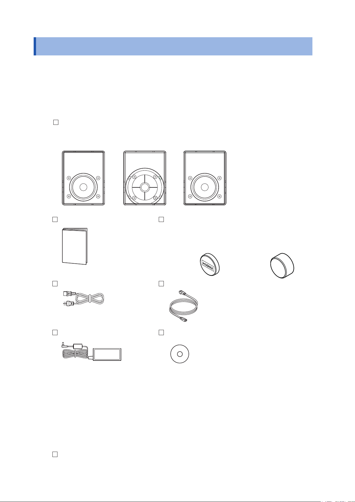
Conrming Package Contents
Conrming Package Contents
When you receive the instrument, inspect it carefully to ensure that no damage occurred during
shipping. In particular, check the accessories and connectors. If damage is evident, or if it fails to
operate according to the specications, contact your authorized Hioki distributor or reseller.
Main unit and accessories
Conrm that these contents are provided.
Model TM6102 RGB Laser Meter
Model TM6103 RGB Laser Luminance Meter
Model TM6104 Optical Power Meter
TM6102
TM6103
TM6104
Instruction Manual (this document) Light shielding cap (Expressed as “cap” in this document)
Instrument is shipped with the cap attached.
Be sure to attach the cap when the instrument is not in use.
For the TM6102 and the TM6104
Power cord LAN cable
Category 6A (CAT 6A)
Straight cable 3 m
Model Z1008 AC Adapter Application disc (CD)
• Application software
RGBLaserUtility
• Communication Command Instruction Manual
(PDF version)
(This manual describes the communication
commands.)
• Sample program
• Software license agreement
• The latest version can be downloaded from our
website.
For the TM6103
Option
The following options are available for the instrument. Contact your authorized Hioki istributor or
reseller when ordering.
Model Z1008 AC Adapter
2
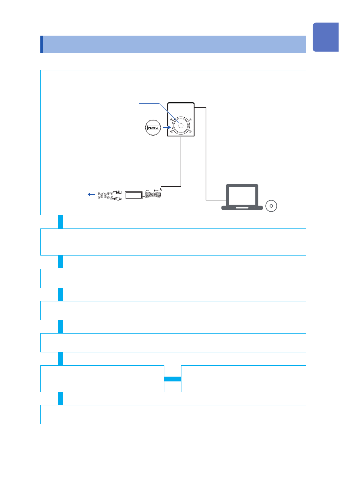
Measurement Flowchart
Measurement Flowchart
Installation
Check that no contaminant or
1
dust is adhered to the detector
window of the instrument.
Attach the cap.
2
Connect the AC adapter. (p. 26)
4
To a commercial
power supply
Illuminance measurement (p. 12), Luminance measurement (p. 16), Optical
power measurement (p. 20)
Before communicating
with the computer
Connect the LAN cable.
3
(p. 30)
Set the communication setting
5
mode. (p. 26)
Turn on the instrument. (p. 27)
6
Warm up for 30 minutes or
longer.
Turn on the computer.
7
• Installing the application software (p. 28)
• External control settings (p. 51)
1
2
3
4
5
6
Communication startup
Measurement condition settings
Dark measurement
(p. 42)
Normal measurement
(p. 45)
End of measurement
Attach the cap.
(p. 35)
White balance adjustment
(p. 46)
7
8
9
10
Appx. Ind.
3
Safety Notes
Safety Notes
This instrument is designed to conform to IEC 61010 Safety Standards, and has been thoroughly
tested for safety prior to shipment. However, using the instrument in a way not described in this
manual may negate the provided safety features.
Before using the instrument, be certain to carefully read the following safety notes.
WARNING
• Protective gears
Wear appropriate protective gear before measuring a strong laser light.
•
With regard to the electricity supply, there are risks of an electric shock, a heat
generation, a re, and an arc ash due to a short-circuit. Individuals using an
electrical measuring instrument for the rst time should be supervised by a
technician who has experience in electrical measurement.
CAUTION
Mishandling during use could damage to the instrument. Be certain that you understand
the instructions and precautions in the manual before use.
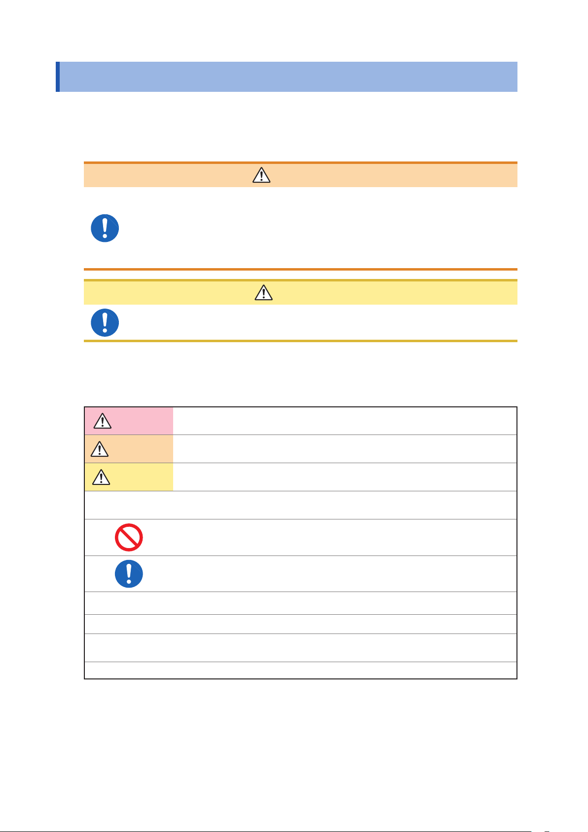
Notations
In this document, the risk seriousness and the hazard levels are classied as follows.
DANGER
WARNING
CAUTION
IMPORTANT
Indicates an imminently hazardous situation that will result in death or serious injury
to the operator.
Indicates a potentially hazardous situation that may result in death or serious injury to
the operator.
Indicates a potentially hazardous situation that may result in minor or moderate injury
to the operator or damage to the instrument or malfunction.
Indicates information related to the operation of the instrument or maintenance tasks
with which the operators must be fully familiar.
Indicates prohibited actions.
Indicates the action which must be performed.
*
p.
[ ]
Unless otherwise specied, “Windows” represents Windows 7, Windows 8, or Windows 10.
•
Additional information is presented below.
Reference
Menus, dialogs, buttons in a dialog, and other names on the screen and the keys are
indicated in brackets.
4
Safety Notes
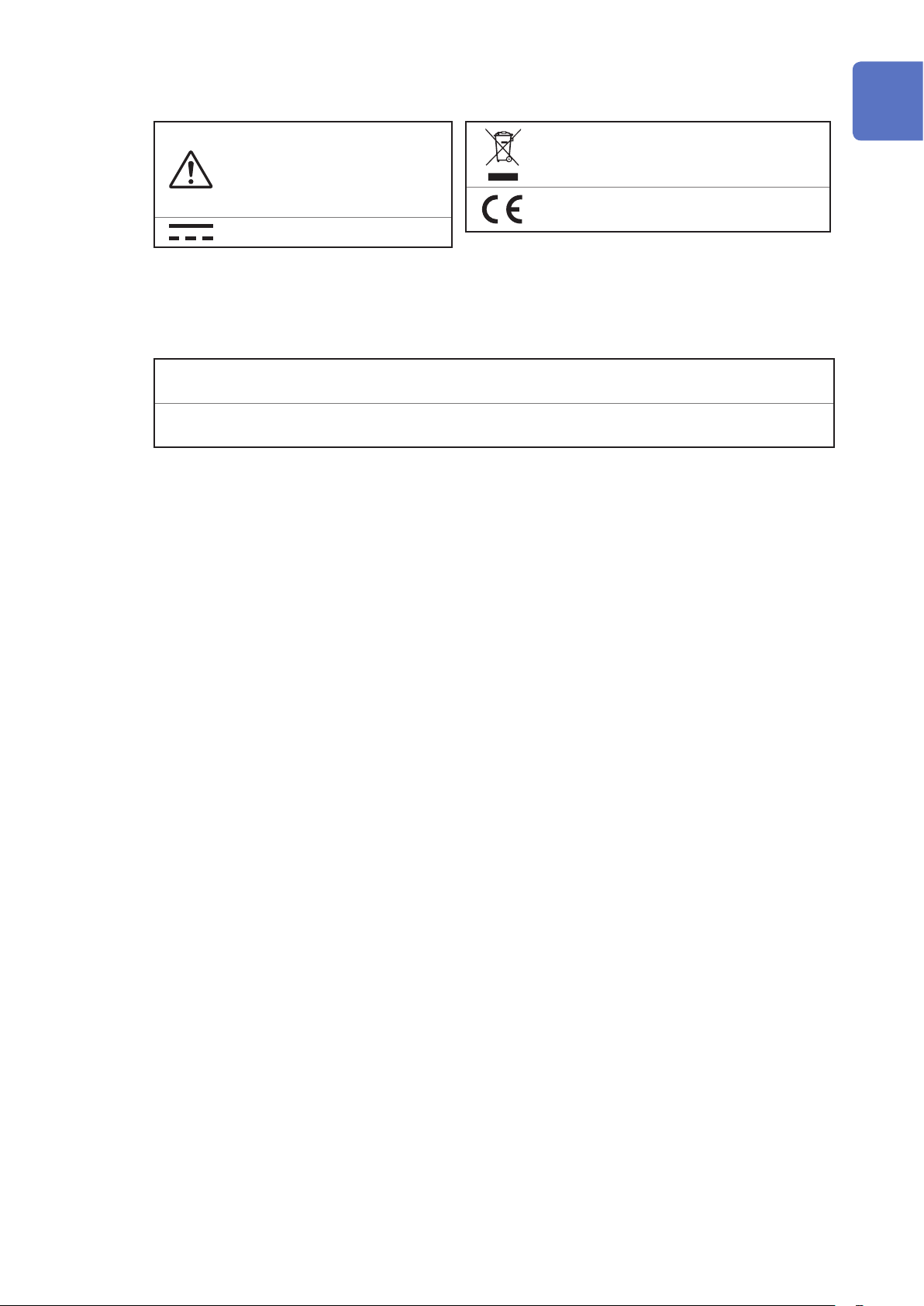
Symbols afxed to the instrument
Indicates cautions and hazards.
When the symbol is printed
on the instrument, refer to a
corresponding topic in the
Instruction Manual.
Indicates DC (Direct Current).
Accuracy
We dene measurement tolerances in terms of f.s. (full scale) and rdg. (reading) values, with the
following meanings:
f.s.
rdg.
f.s. (Maximum display value)
The maximum display value. Generally, this value indicates the range currently being used.
(Reading or displayed value)
The value currently being measured and displayed on the measuring instrument.
Symbols for various standards
Indicates the Waste Electrical and Electronic
Equipment Directive (WEEE Directive) in EU
member states.
Indicates that the product conforms to
regulations set out by the EU Directive.
1
2
3
4
5
6
7
8
9
10
Appx. Ind.
5
Usage Notes
Usage Notes
• Follow these precautions to ensure safe operation and to obtain the full benets of the various
functions.
• Ensure that your use of the product falls within the specications not only of the instrument itself,
but also of any accessories, options and other equipment being used.
• Before using the instrument, verify that it operates normally to ensure that no damage occurred
during storage or shipping. If you nd any damage, contact your authorized Hioki distributor or
reseller.
• This instrument may cause interference if used in residential areas. Such use must be avoided
unless the user takes special measures to reduce electromagnetic emissions to prevent
interference to the reception of radio and television broadcasts.
• The instrument itself does not radiate any laser light. However, when a strong
laser light is irradiated to the detector window of the sensor, a strong reected
light is generated. In this case, do not look into the detector window directly.
Doing so may adversely affect your eyes or cause visual disturbance.
The instrument can measure lasers classied into classes I to IIIB. As required,
refer to the risks during measurement of the relevant class laser and cautions
on use stated in IEC60825-1 and FDA21CFR1040.10. When handling a laser
product, always follow the caution and warning labels adhered to the laser
product, and the contents described in the instruction manual.
• Refer to the description of safe use of the laser and laser system stated in
ANSI Z136.1. Only authorized operators who have trained in operation of the
laser and laser system are allowed to perform the measurement.
• Do not input a light exceeding the maximum input level. Otherwise, accurate
measurements cannot be performed or the sensor may be damaged by
excessive energy
• When an extremely focused beam is measured, the energy density on the
sensor is excessive, causing inaccurate measurements. In addition, the sensor
may deteriorate.
• To avoid the risk of re, do not irradiate a strong laser light to the instrument
or cap, nor focus a strong laser light on the instrument or cap. In particular, do
not place any combustible materials near the instrument in the unmanned state
such as automatic measurement.
• Use only the supplied Model Z1008
range is 100 V to 240 V AC at a frequency of 50 Hz/60 Hz. To avoid electrical
hazards and damage to the instrument, do not apply voltage outside of this
range.
• To prevent an electrical shock and to maintain the safety specications of this
instrument, connect only the power cord provided to an outlet.
WARNING
.
AC Adapter. The AC adapter input voltage
6
CAUTION
• Avoid using an uninterruptible power supply (UPS) or DC/AC inverter with rectangular
wave or pseudo-sine-wave output to power the supplied AC adapter. Doing so may
damage the instrument.
• The instrument consists of precision optical components. Dropping the instrument
or subjecting it to mechanical shock may damage it. Optical components inside the
instrument may fall out of alignment if the instrument is dropped or subjected to
mechanical shock, affecting measured values.
• To avoid damage to the instrument, protect it from physical shock when transporting
and handling it. Be especially careful to avoid physical shock due to dropping it.
• Do not connect the power supply improperly. Doing so may damage the instrument’s
internal circuitry.
• If a light outside the measurement wavelength range enters, this may cause the
sensor to deteriorate. Attach the cap when the instrument is not in use.
• Attach the cap when the instrument is not used for a long time.
Installing the instrument
Installing the instrument in inappropriate locations may cause a malfunction of instrument or may
give rise to an accident. Avoid the following locations.
Usage Notes
1
2
3
4
WARNING
• Exposed to direct sunlight or high temperature
• Exposed to corrosive or combustible gases
• Exposed to water, oil, chemicals, or solvents
• Exposed to high humidity or condensation
• Exposed to a strong electromagnetic eld or electrostatic charge
• Exposed to high quantities of dust particles
• Near induction heating systems (such as high-frequency induction heating
systems and IH cooking equipment)
• Susceptible to vibration
CAUTION
• Do not place the instrument on an unstable table or an inclined place. Dropping or
knocking down the instrument can cause injury or damage to the instrument.
• The instrument consists of precision optical components. The instrument should be
securely mounted on a jig using the screw hole in its base. Dropping the instrument or
applying an impact to it can cause the accuracy to deviate from its specication. If an
impact is applied to the instrument, it needs to be inspected.
• When orienting the instrument so that a part other than its base is facing down, x it
in place so that it cannot fall. Failure to do so may cause a re or other malfunction in
the instrument.
• The instrument is housed in a metal case and emits heat. Be sure to leave adequate
space around the instrument. Failure to do so may cause the ambient temperature to
rise, affecting measured values and potentially damaging the instrument.
• Install the instrument so that no load is applied to the detector window.
5
6
7
8
9
10
Appx. Ind.
In an emergency, unplug the power cord to kill power to the instrument. Be sure to provide enough
unobstructed space to unplug the power cord immediately.
7
Usage Notes
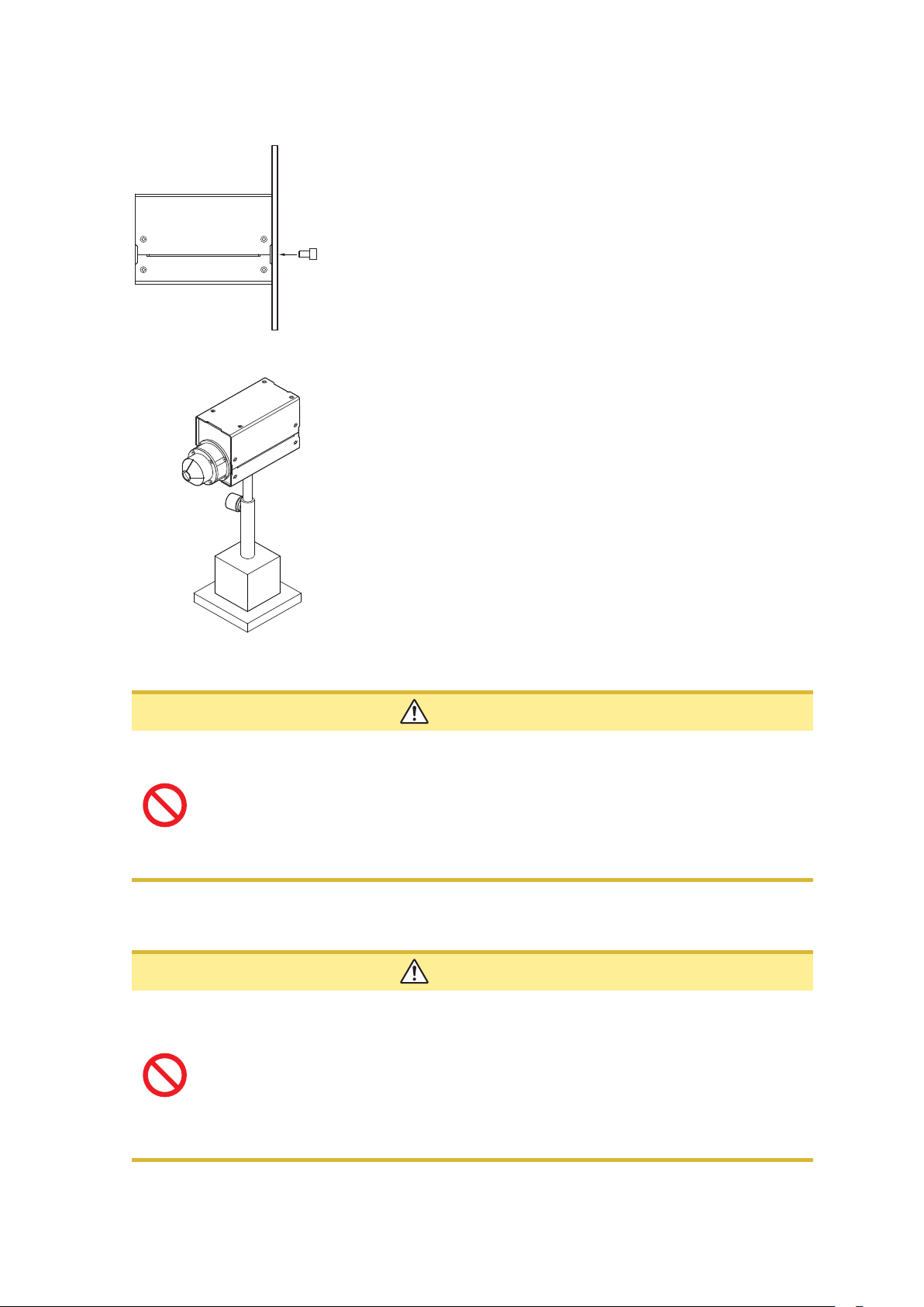
Securing the instrument
Securing the instrument using the tripod mounting screw holes in the rear
• Install the instrument using the tripod mounting screw holes in
the rear.
• Sufciently strengthen the surface on which the instrument is
installed so that the instrument is not unstable.
• For the TM6103, securing only the rear may cause an unstable
installation of the instrument. Therefore, be sure to secure the
instrument using the tripod mounting screws on the bottom.
Usable screw: 1/4-20UNC, hole depth 7.5 mm
Securing the instrument using the tripod mounting screw holes in the bottom
• Install the instrument using the tripod mounting screw holes in
the bottom.
Usable screw: 1/4-20UNC hole depth 7.5 mm
• A stand and others necessary for the installation work should be
prepared by the customer.
Detector window (face detecting the light)
CAUTION
• Do not touch the detector window. The instrument may fail to operate to its full level of
performance if the detector window is dirty.
• Avoid contacting the detector window with sharp objects (the tip of a pair of
tweezers, etc.) or hard surfaces. The instrument may fail to operate to its full level of
performance if the detector window is damaged.
• Never use solvents that contain benzene, alcohol, acetone, ether, ketones, thinners or
gasoline. They can deform and discolor the detector window. (p. 93)
Light shielding cylinder (TM6103)
CAUTION
When handling the TM6103, observe the following cautions to perform correct
measurement.
• Do not put any foreign object in the light shielding cylinder.
• Do not apply a large load to the light shielding cylinder.
• Do not touch the inside of the light shielding cylinder with bare hands.
• Do not damage the inside of the light shielding cylinder using a sharp object.
• Do not apply an impact to the light shielding cylinder.
• Never attempt to modify, disassemble, or repair the light shielding cylinder.
8
AC Adapter
Usage Notes
WARNING
• Turn the instrument off before connecting the AC adapter to the instrument and
to AC power.
• Use only the supplied Model Z1008 AC Adapter.
1
Before starting the external control
To avoid damage to the instrument, do not apply a voltage exceeding the rated
maximum to the external input terminals.
• Always turn both devices OFF when connecting and disconnecting an interface
connector. Otherwise, an electric shock may occur.
• To avoid an electric shock or damage to the equipment, always observe the
following precautions when connecting to the external input terminals:
• Always turn off the power to the instrument and to any devices to be
connected before making connections.
• Be careful to avoid exceeding the ratings of the external input terminals.
• Connect cables securely to the external connector. During operation, a
wire becoming dislocated and contacting another conductive object can be
serious hazard.
• Use a common ground for both the instrument and the computer. Using different
ground circuits will result in a potential difference between the instrument’s ground
and the computer’s ground. If the communications cable is connected while such a
potential difference exists, it may result in equipment malfunction or failure.
• Before connecting or disconnecting any communications cables, always turn off the
instrument and the computer. Failure to do so could result in equipment malfunction
or damage.
• To prevent equipment failure, use the recommended wire type to connect to the
external input terminals.
Recommended wire
Single strand: φ0.65 mm (AWG #22)
Multi-strand: 0.32 mm
2
2
DANGER
3
WARNING
4
5
6
CAUTION
7
8
9
(AWG #22)
Acceptable limits
Single strand: φ0.32 mm to φ0.65 mm (AWG #28 to #22)
Multi-strand: 0.08 mm
Strand diameter: minimum φ0.12 mm (per strand)
Standard insulation stripping length: 9 mm to 10 mm
Button pressing tool: Blade screwdriver (shaft diameter: 3 mm, tip width 2.6 mm)
2
to 0.32 mm2 (AWG #28 to #22)
10
Appx. Ind.
9

Usage Notes
CD precautions
• Exercise care to keep the recorded side of discs free of dirt and scratches. When writing text on a
disc’s label, use a pen or marker with a soft tip.
• Keep discs inside a protective case and do not expose to direct sunlight, high temperature, or
high humidity.
• Hioki is not liable for any issues your computer system experiences in the course of using this
disc.
10

1
Overview
1.1 Overview and Features
The instrument measures the centroid wavelength and radiometric quantity of laser light sources
and calculates the chromaticity and photometric quantity.
In addition, the target value of the radiometric quantity (each of the red, green, and blue radiometric
quantities) and the tolerance of the radiometric quantity necessary to adjust the chromaticity and
photometric quantity to specied values are presented.
All of the control and display of the measurement are performed on the computer.
Highly accurate measurement dedicated for RGB lasers
The centroid wavelengths and radiometric quantities of the red, green, and blue lasers are
measured simultaneously by means of the discrete centroid wavelength method*.
Additionally, the highly accurate photometry and colorimetry are achieved.
*: A method to measure the red, green, and blue centroid wavelengths and radiometric quantities
of the RGB laser and calculate the chromaticity and photometric quantity from the color-matching
function.
The industry’s rst traceability to national standards in laser illuminance
The industry’s rst traceability to national standards in laser illuminance was achieved using a
monochromatic laser source. (As of May, 2017)
It is Hioki’s original compliant, which renovates the conventional traceability to the standard lamp.
1
Overview
Shortening of adjustment process
When the white balance is adjusted, the target value of the radiometric quantity and the tolerance
of the radiometric quantity are calculated from the measured result to contribute to shortening of
the adjustment process.
Stable high-speed measurement
Various modulation frequencies (screen refresh rates) are supported to ensure stable
measurement.
Measurement of centroid wavelength
In addition to the chromaticity and photometric quantity, the centroid wavelength, which is used to
control the RGB laser module product itself, can be measured.
In addition, the measured centroid wavelength is utilized for the quality control or production control
of the RGB laser module.
Sensors suitable for the measuring object
Three types of sensors, illuminance (TM6102), luminance (TM6103), and optical power (TM6104),
suitable for various measuring objects such as HMD, HUD, and projector or various measurement
scenes in the production process, are prepared.
11
Model TM6102 RGB Laser Meter
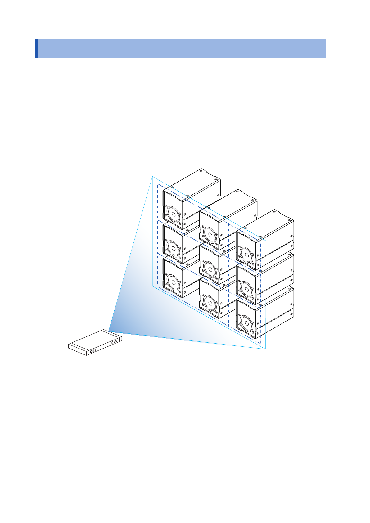
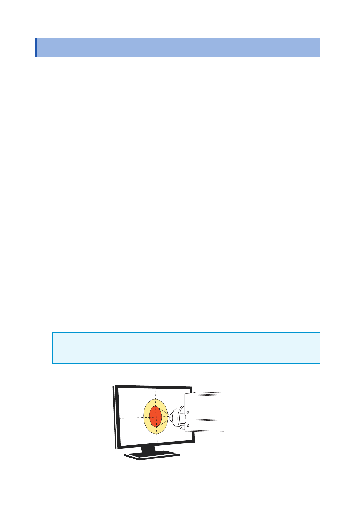
1.2 Model TM6102 RGB Laser Meter
The TM6102 RGB Laser Meter measures the light that is irradiated uniformly to the entire detector
window from the RGB laser module of the projector or HUD (head up display).
The reference surface of the illuminance measurement is REF.LEVEL shown in the drawings of the
dimensions. (p. 15)
The measurement settings and measurement items except for the following points are the same as
the TM6103 and TM6104.
• Radiometric quantity → Irradiance
• Photometric quantity → Illuminance
Measurement example
12
Example: Laser projector
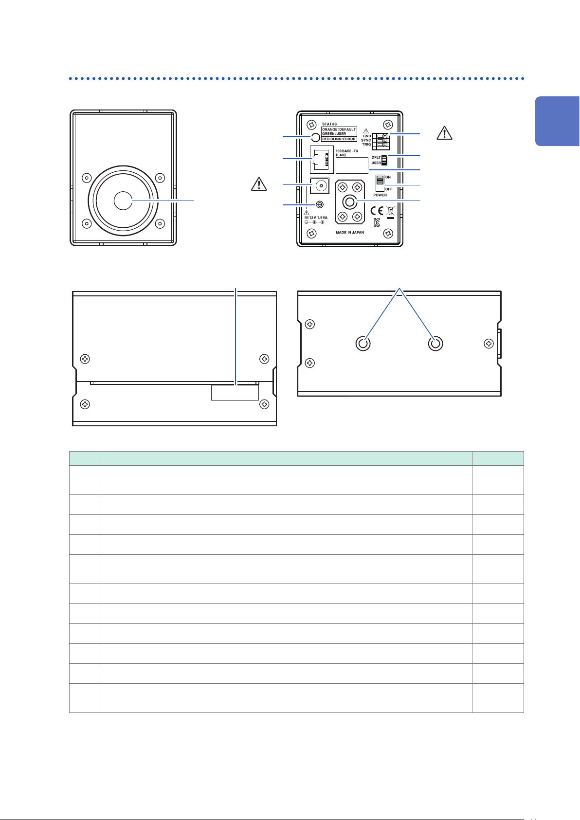
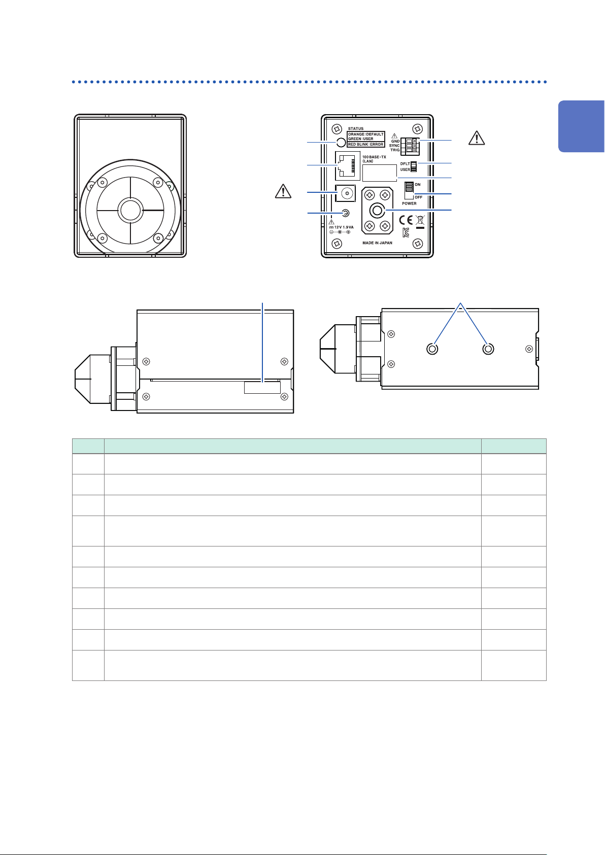
Parts Names and Functions
Model TM6102 RGB Laser Meter
Front
Right side
Rear
2
3
6
7
(p. 9)
1
Overview
8
(p. 6)
1
11
4
5
Bottom
9
10
10
No. Description Reference
Detector window
1
(φ11.3 mm ±0.1 mm)
Power LED p. 27
2
LAN connector p. 29
3
AC adapter connector p. 26
4
General purpose screw hole
5
(Used to secure the power cord.)
External input terminals p. 51
6
Communication mode switch p. 26
7
MAC address
8
Power switch p. 27
9
Tripod mounting screw holes p. 8
10
Serial No.
11
(Do not peel off the label because it is necessary for production control.)
p. 8
–
–
–
13
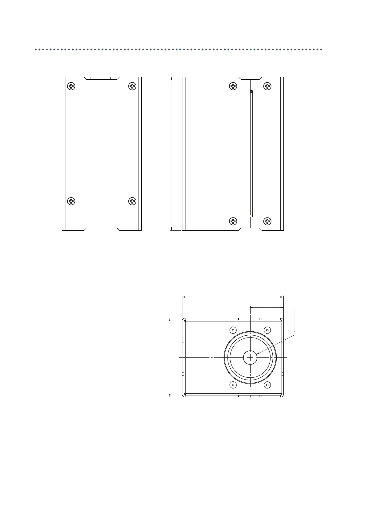
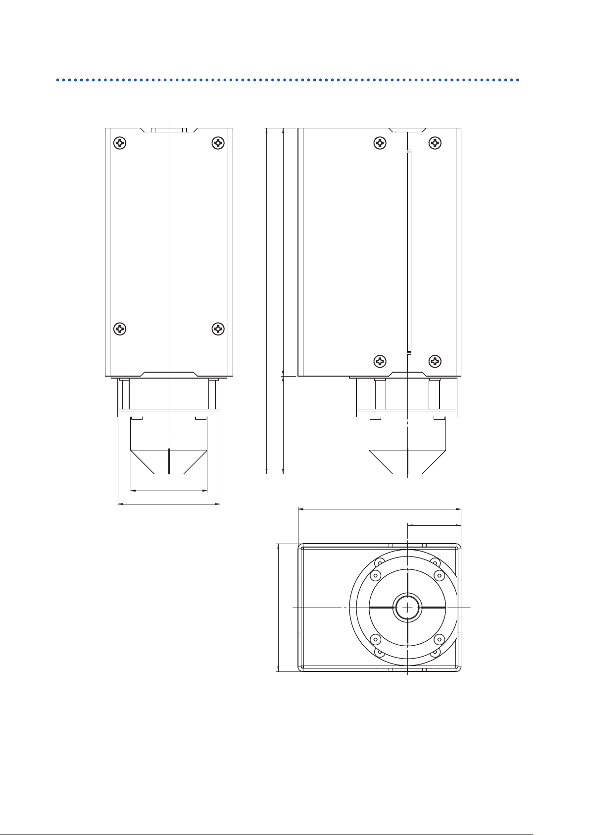
Model TM6102 RGB Laser Meter
C
L
±1
65
83 ±1
±0.5
27.3
11.3
±0.1
126
±1
Dimensions
65±1
83 ±1
27.3 ±0.5
11.3 ±0.1
φ
(Unit : mm)
14
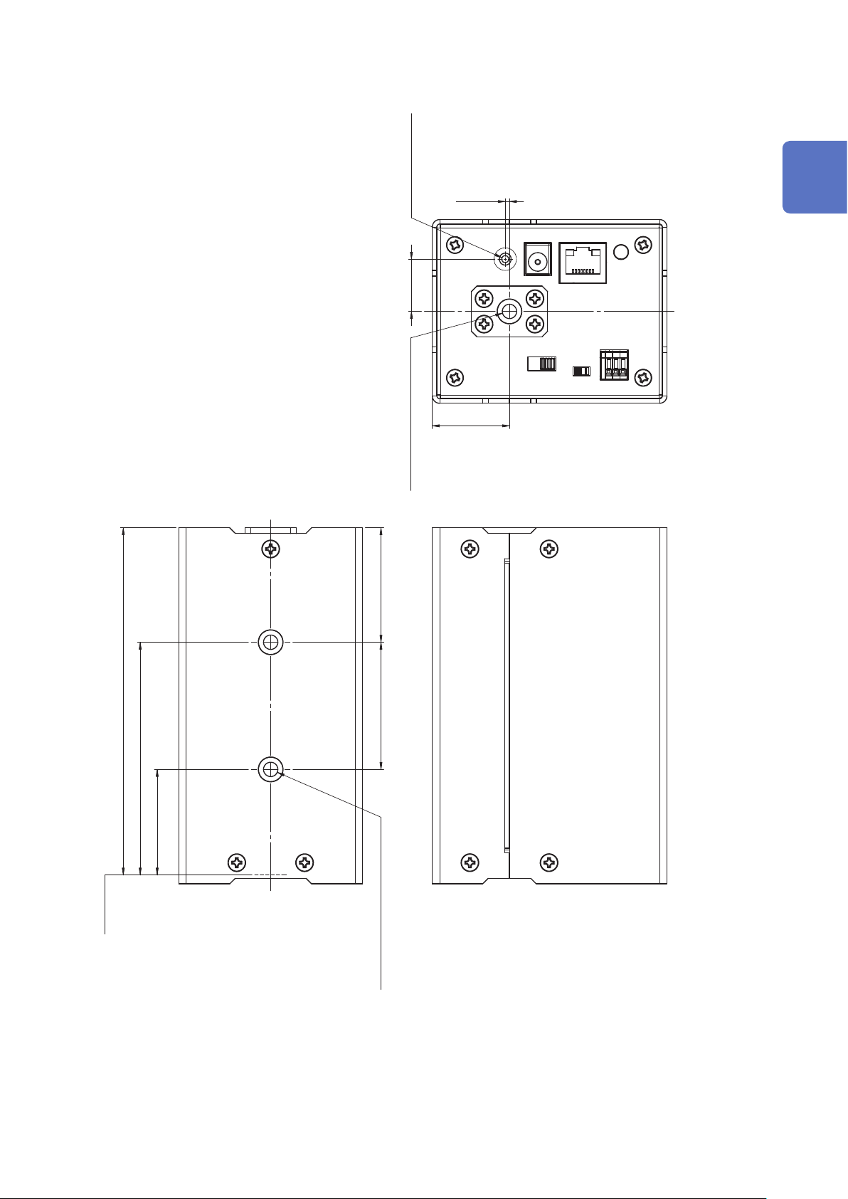
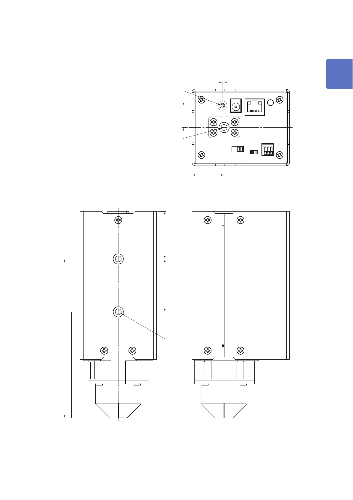
Model TM6102 RGB Laser Meter
M3 Effective Depth 5
1.5 ±0.3
1
Overview
18.5
±0.5
C
L
1/4-20UNC Effective Depth 7.5
27.3
±0.5
C
L
122.85
±1
±0.5 82.35
37.35
±0.5
REF.LEVEL
(Measurement reference surface)
(45) 5.7 htpeD evitceffE CNU02-4/1 ×2 )5.04(
(Unit : mm)
15
TM6103 RGB Laser Luminance Meter
1.3 TM6103 RGB Laser Luminance Meter
The TM6103 RGB Laser Luminance Meter is a light shielding cylinder type luminance meter.
The TM6103 measures the luminance at a close range of the display (example: the distance from
the top end of the light shielding cylinder to the display is 10 mm).
Before starting the measurement, install the TM6103 so that it is perpendicular to the display. (To
measure the luminance more accurately, align the light axis of the light emitted from the display and
the light axis of the TM6103.)
The light source that becomes the measuring object needs to be larger than the measurement eld
diameter of the TM6103.
To perform accurate measurements, it is recommended to measure the light source that is
sufciently larger than the measurement eld diameter.
The TM6103 measures the average luminance within the measurement eld diameter in the same
way as the conventional luminance meter.
When a directional light source (light source with an inconstant luminance) is measured using
luminance meters with different angle-of-visibilities, the measured value that differs among them.
This phenomenon occurs because the calibration light source of the luminance meter has a
constant luminance area, but the measuring object does not have one.
• When the light source of the measuring object has a constant luminance area, differences in the
angle-of-visibility do not affect the measured luminance value.
• The measured luminance is a value for which the angle dependency of the light source luminance
is averaged by the angle-of-visibility. Therefore, when the light source of the measuring object
does not have a constant luminance area, the angle-of-visibility of the luminance meter affects
the measured luminance value, in principle.
To perform the measurement with excellent reproducibility, it is necessary to align the light axis
of the light emitted from the display and the light axis of the luminance meter. In this case, it is
recommended to use an optical bench.
The measurement settings and measurement items except for the following points are the same as
the TM6102 and TM6104. (p. 12)
• Radiometric quantity → Radiance
• Photometric quantity → Luminance
CAUTION
Removing or disassembling the light shielding cylinder may cause inaccurate measurements. (p. 8)
Never attempt to remove or disassemble the light shielding cylinder.
Measurement example
16
Light source (Target)
Parts Names and Functions
Front Rear
TM6103 RGB Laser Luminance Meter
Right side
(p. 6)
10
1
2
3
4
Bottom
5
(p. 9)
1
Overview
6
7
8
9
9
No. Description Reference
Power LED p. 27
1
LAN connector p. 29
2
AC adapter connector p. 26
3
General purpose screw hole
4
(Used to secure the power cord.)
External input terminals p. 51
5
Communication mode switch p. 26
6
MAC address –
7
Power switch p. 27
8
Tripod mounting screw holes p. 8
9
Serial No.
10
(Do not peel off the label because it is necessary for production control.)
–
–
17
TM6103 RGB Laser Luminance Meter
Dimensions
126 ±0.5
175.7 ±1
175.7 ±1
126 (49.7) ±0.5
39 ±0.5
φ
52 ±0.5
φ
L
C
L
C
±0.5
39
52 ±0.5
±1
L
C
65 ±1
65
83 ±1
83 ±1
27.3 ±0.5
±0.5 27.3
(Unit : mm)
18
TM6103 RGB Laser Luminance Meter
1.5
±0.3
1
Overview
18.5 ±0.5
C
L
5 htpeD evitceffE 3M 1/4-20UNC Effective Depth 7.5
27.3 ±0.5
C
L
(40.5)
(45)
135.2
±0.5
90.2
±0.5
2× 1/4-20UNC Effective Depth 7.5
(Unit : mm)
19
Model TM6104 Optical Power Meter
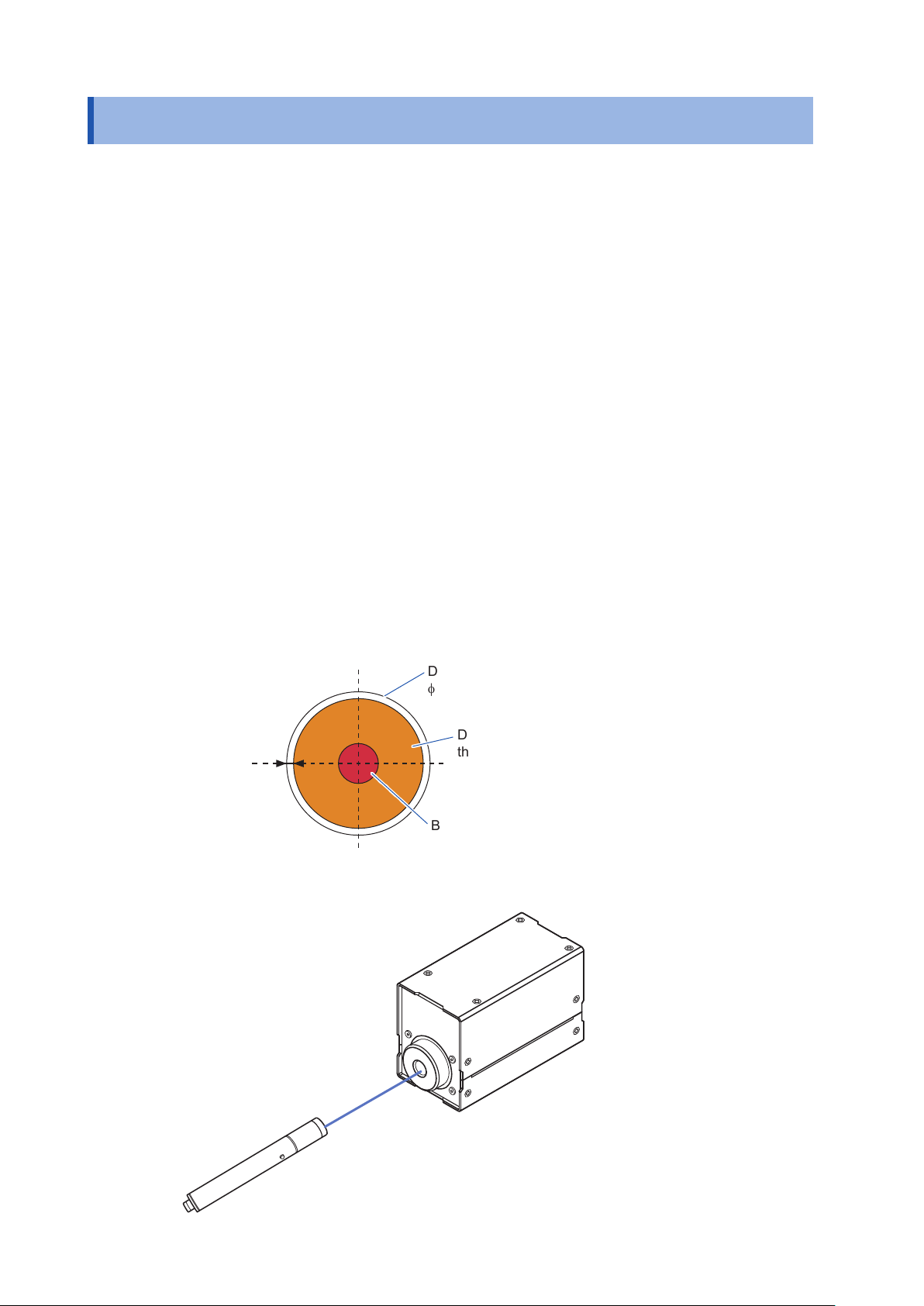
1.4 Model TM6104 Optical Power Meter
The TM6104 Optical Power Meter measures the power and centroid wavelength of the laser beam
irradiated at the center of the detector window.
When performing the measurement, you have to consider the beam diameter.
The beam diameter is dened as a maximum distance between the points in the cross section
of the beam where the optical power density is e
(JIS C6182).
Although IEC1040 adopts e
−1
as the denition of a beam diameter instead of e−2, this instrument
uses the denition of JIS C6182.
To perform accurate measurements, it is necessary to make all powers of the beam enter the
detector window.
In addition, it is recommended to use a laser with a beam diameter of 3.1 mm or less so as to
perform accurate measurements.
This makes the diameter that is 3 times larger than the beam diameter smaller than the diameter of
the detector window (= φ11.3 mm) as a guide since the beam usually has a spread.
Example: When the beam diameter is 1 mm, make the beam enter an area within 6 mm dia. from
the center of the detector window.
−2
(= 0.1353) to the maximum value in the beam
However, this does not apply when the beam has no spread.
The measurement settings and measurement items except for the following points are the same as
the TM6102 and TM6103. (p. 12)
• Radiometric quantity → Radiant ux (Optical power)
• Photometric quantity → Luminous ux
Detector window
11.3 mm
φ
1 mm
Diameter 3 times larger than
the beam diameter
9.3 mm (Maximum value)
φ
Beam diameter
3.1 mm (Maximum value)
φ
Measurement example
Layout of optical system
20
Laser light source
Parts Names and Functions
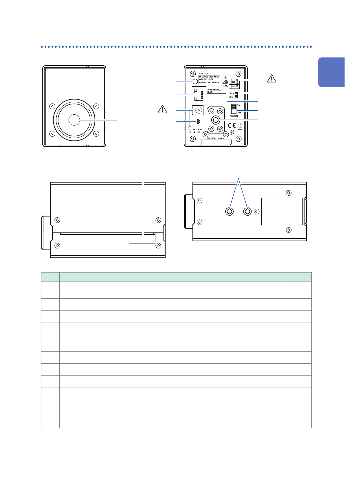
Model TM6104 Optical Power Meter
Front
Right side
Rear
2
3
6
7
(p. 9)
1
Overview
8
(p. 6)
1
11
4
5
Bottom
9
10
10
No. Description Reference
Detector window
1
(φ11.3 mm ±0.1 mm)
Power LED p. 27
2
LAN connector p. 29
3
AC adapter connector p. 26
4
General purpose screw hole
5
(Used to secure the power cord.)
External input terminals p. 51
6
Communication mode switch p. 26
7
MAC address –
8
Power switch p. 27
9
Tripod mounting screw holes p. 8
10
Serial No.
11
(Do not peel off the label because it is necessary for production control.)
p. 8
–
–
21
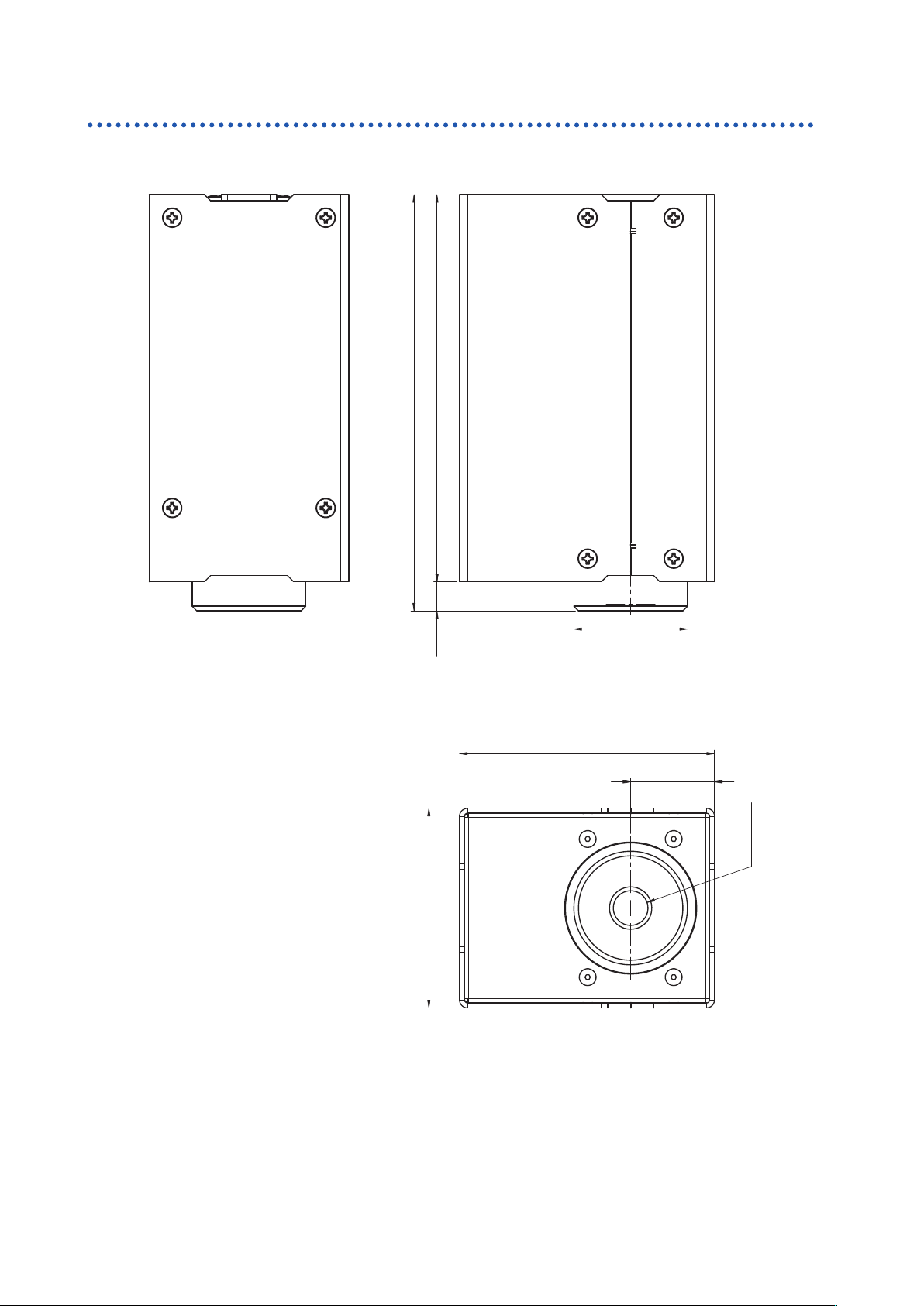
Model TM6104 Optical Power Meter
Dimensions
±1
±0.5
621 )5.9(
135.5 ±1
126 ±0.5
135.5
±1
65 ±1
65
37 ±0.5
φ
37
±0.5
83 ±1
83 ±1
27.3 ±0.5
L
C
27.3 ±0.5
11.3 ±0.1
Detector window
11.3 ±0.1
受光面
φ
(Unit : mm)
22
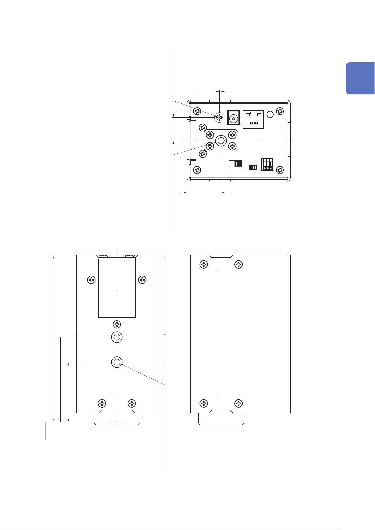
±0.5
67.75
47.75
±0.5
133.25
±1
受光面
C
L
2× 1/4-20UNC Effective Depth 7.5
(20)
(65.5)
C
L
±0.5
M3 Effective Depth 5 1/4-20UNC Effective Depth 7.5
27.3
±0.5
18.5
1.5
±0.3
Model TM6104 Optical Power Meter
1
Overview
Detector window
(Unit : mm)
23

Model TM6104 Optical Power Meter
24

2
Preparations
2.1 Inspection Before Measurement
Check before use
Before using the instrument, verify that it operates normally to ensure that no damage occurred
during storage or shipping. If you nd any damage, contact your authorized Hioki distributor or
reseller.
Inspecting peripheral devices
Check item Action
Using a damaged connection cable may cause an electrical
Is the sheath of any connection cable damaged or
any metal part exposed?
Inspecting the instrument
Check item Action
shock or a short circuit accident. Do not use any damaged
connection cable.
Replace the damaged connection cable with a new one.
2
Preparations
Is the instrument damaged? If the instrument is damaged, send the instrument for repair.
Is any dust or contaminant adhered to the detector
window?
Does the power LED light up?
Execute the self-test to check if an error occurs.
(Use the
When no error occurs,
When an error occurs,
Input the modulation frequency signal to the SYNC
terminal and execute the modulation frequency
measurement. Is the measured result of the
modulation frequency within the assumed range?
TST?
command to execute the self-test.
*
PASS
is returned.
FAIL
is returned.)
If the detector window is contaminated, clean it. (p. 93)
• If the power LED does not light up, the power cord contains
a broken wire or the inside of the instrument malfunctions. If
the instrument malfunctions, send it for repair. (p. 27)
• If the power LED blinks in red, an error occurred inside the
instrument. After connecting the instrument via TCP/IP, use
ESR?,:SYSTem:ERRor?
the
*
of the error, and then take appropriate corrective actions
corresponding to the error.
Details of error: Communication Command Instruction
Manual (CD)
• When an error occurs, use the
to check the details of the error, and then take appropriate
corrective actions corresponding to the error.
• For details about the error, see the Communication Command
Instruction Manual (CD).
• When executing the self-test using the application software,
see “Self-test” (p. 79).
If the measured result of the modulation frequency is not
within the assumed range, the inside of the instrument may
malfunction. Send the instrument for repair.
command to check the details
:SYSTem:ERRor?
command
Is the measured value of the photometric quantity
changed by changing the brightness of the
irradiation light?
Is the measured result of the centroid wavelength
within the assumed range when the laser light
source with the known wavelength is measured?
If the measured value of the photometric quantity is not
changed, the inside of the instrument may malfunction. Send
the instrument for repair.
If the measured result of the centroid wavelength is not
within the assumed range, the inside of the instrument may
malfunction. Send the instrument for repair.
25
Connecting the AC Adapter and Power Cord
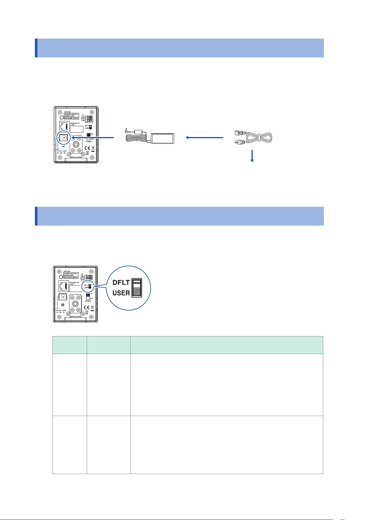
2.2 Connecting the AC Adapter and Power Cord
Check the following points before starting the connection work.
• Check that the cap is attached to the detector window.
• Thoroughly read “AC Adapter” (p. 9).
Rear
Connect the AC adapter to
1
the AC adapter connection
terminal of the instrument.
Connect the power cord to
2
the AC adapter.
Connect the power cord
3
to a commercial power
supply.
2.3 Setting the Communication Setting Mode
Change the LAN communication setting mode using the communication setting mode switch. (p. 31)
The LAN communication setting mode cannot be changed when the power is ON.
Rear
26
Switch
DFLT
USER
Communication
setting mode
Fixed setting
mode
User setting
mode
Settings
• The LAN settings are as follows.
IP address: 192.168.0.254
Subnet mask: 255.255.255.0
Default gateway: 0.0.0.0 (None)
Communication command port: 1024
• The xed setting mode is used to make the LAN settings.
• The xed setting mode can also be used when one-to-one communication
with the computer is performed.
Use the LAN settings that are set using the following communication
commands.
:SYSTem:COMMunicate:LAN:IPADdress <IP
:SYSTem:COMMunicate:LAN:SMASk <
:SYSTem:COMMunicate:LAN:GATeway <
:SYSTem:COMMunicate:LAN:CONTrol <
:SYSTem:COMMunicate:LAN:UPDate
Subnet mask
Address
Port No.
address
>
>
>
>
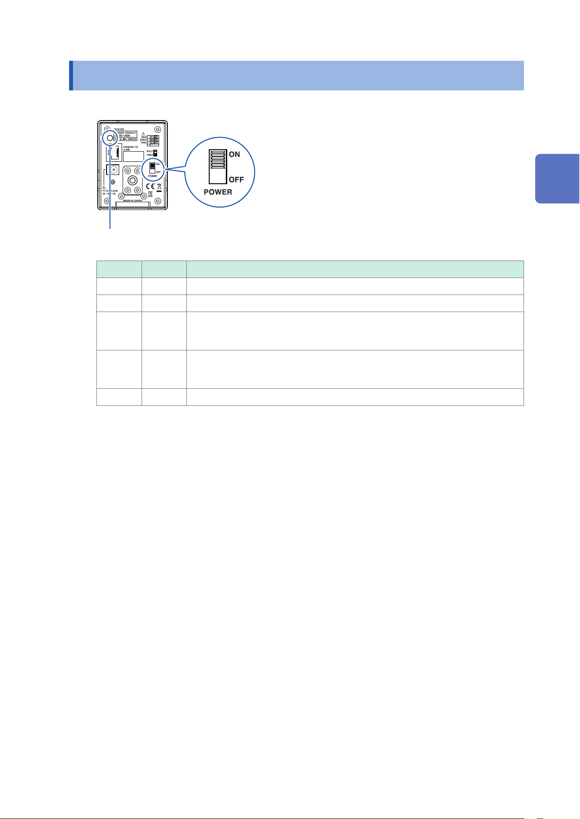
Turning ON/OFF the Power
2.4 Turning ON/OFF the Power
Rear
Power LED
Color Status Description
Green Lit Running when the communication setting mode is set to the user setting mode.
Orange Lit Running when the communication setting mode is set to the xed setting mode.
2
Preparations
An internal error is occuring.
Red Blink
Orange Blink
‒ Off The power is off.
Use the communication command (
See: Communication Command Instruction Manual (CD)
Running in the version up mode (boot mode).
The communication setting mode becomes the xed setting mode regardless of the
communication setting mode switch state.
ESR?, :SYSTem:ERRor?
*
) to check the details.
27
 Loading...