

Page 1
SP7001/SP7002 NON-CONTACT CAN SENSOR
HIOKI SP7001A971-01
SP7100/SP7150 CAN INTERFACE
SP9200/SP9250 SIGNAL PROBE
Quick Start Manual
EN
July 2021 Revised edition 1
SP7001A971-01 21-07H
* The SP9200 Signal Probe and SP9250 Signal Probe are not
covered by the warranty.
Introduction
Thank you for choosing the Hioki SP7001/SP7002 Non-Contact
CAN Sensor, SP7100/SP7150 CAN Interface, and SP9200/SP9250
Signal Probe. Keep this manual accessible so that you can take full
advantage of the product’s functionality throughout its service life.
Be sure to review the following documentation before using the
product:
–
Electronic
edition
–
–
Document Content
Quick Start
Manual
(this manual)
Instruction
Manual
Operating
Precautions
(0990A905)
This is the Quick Start Manual. Be sure to download the most
recent version of the Instruction Manual from Hioki’s website.
https://www.hioki.com/en/products/detail/?product_key=6509
The Quick Start Manual
provides a brief overview
of how to use the product.
The Instruction Manual
contains detailed
instructions about how to
use the product.
“Operating Precautions”
contains important
information about how to
use the product safely.
Paper
edition
Communications standards
The Non-Contact CAN Sensor supports the following
communications standards:
Model Communications standards
SP7001
SP7002
–
Use of the product
Before using the product, review proper handling of the product, bus
systems, and related systems.
Only individuals who understand both safe product use and the
potential impacts arising from using the product should use the
product. Use of the product by others may cause bodily injury or
damage to the product or other devices.
Overview
The SP7001/SP7002 Non-Contact CAN Sensor can detect CAN
communications signals, which are used in control communications
in automobiles and in a variety of devices, from outside cables’
insulation.
Captured CAN signals can be connected to analyzers, loggers, and
other measuring instruments with a CAN interface.
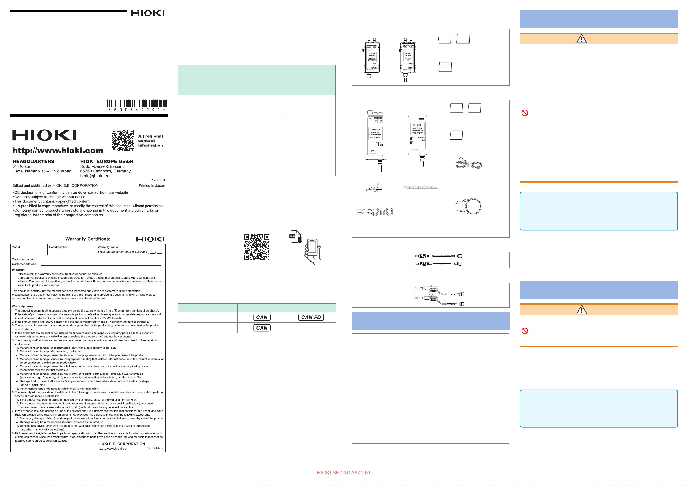
Verifying Package Contents
SP7001/SP7002 Non-Contact CAN Sensor
SP7001 ×1 SP7002 ×1
Quick Start Manual
Japanese and English ×1 each
or
Operating Precautions (0990A905) ×1
SP7100/SP7150 CAN Interface
SP7100 ×1
Alligator clip ×1
Ground connection cable (1.5 m) ×1
SP7150 ×1
or
Spiral tube ×1
(For securing the power
cable in place)
Quick Start Manual
Japanese and English ×1 each
Operating Precautions
(0990A905) ×1
For SP7100
L9500 Power Cable ×1
(For connecting an external
battery; terminates in wires;
approx. 2 m long)
For SP7150
L9510 USB Cable ×1
(Type-A Type-C; for power
supply; 1 m long)
SP9200 Signal Probe
SP9200 ×2
SP9250 Signal Probe
SP9250 ×2
Specications
Operating
environment
Operating
temperature
and humidity
Storage
temperature
and humidity
Dustproofness
and
waterproofness
For other specications, see “4 Specications” in the downloaded
Instruction Manual.
Indoors, Pollution Degree 2
altitude up to 2000 m (6562 ft.)
Temperature: −40°C to 85°C (−40°F to 185°F)
Humidity:
−40
C to 60°C (−40°F to 140°F), 80% RH or
°
less (no condensation)
60°C to 85°C (140°F to 185°F), 60% RH or
less (no condensation)
−40°C to 85°C (−40°F to 185°F)
80% RH or less (no condensation)
IP40 (EN 60529)
SP7001/SP7002: When 2 Signal Probes
connected
SP7100/SP7150: When Non-Contact CAN
Sensor connected
Operating Precautions
WARNING
Do not use the product in locations such as those listed
below. Doing so may result in product damage or cause
an accident.
• Locations where the product would be subject to
direct sunlight or high temperatures
• Locations where corrosive or explosive gases are
present
• Locations where there is powerful electromagnetic
radiation or that are close to electrically charged
objects
• Close to inductive heating equipment (high-frequency
inductive heating equipment, IH cooktops, etc.)
• Locations with an excessive amount of mechanical
vibration
• Locations where the product would be exposed to
water, oil, chemicals, solvents, or other liquids
• Locations with excessive humidity or condensation
• Locations with excessive dust
IMPORTANT
When using the SP7150 CAN Interface:
The product requires a current of at least 200 mA to operate.
If supplying power from a USB terminal with USB bus power
functionality, verify that the device operates properly prior to use.
The Non-Contact Sensor is capable of extremely stable CAN frame
acquisition. However, the product is not guaranteed to achieve
an error rate of 0% under all conditions. Errors may be caused by
factors including the condition of the vehicle being tested and the
quality of the power supply being used. Please verify that the product
functions properly with the vehicle to be tested prior to use.
Maintenance and Service
WARNING
Do not attempt to modify, disassemble, or repair the
product.
Doing so may result in re, electric shock, or bodily
injury.
Troubleshooting
If you believe the product may be malfunctioning, contact your
authorized Hioki distributor or reseller after reviewing the contents of
downloaded Instruction Manual “Before sending the product to be
repaired.”
IMPORTANT
When shipping the product, do not disconnect the SP9200/
SP9250 Signal Probes from the SP7001/SP7002 Non-Contact
CAN Sensor. Doing so may soil or degrade the connectors’
contacts, adversely impacting signal detection.
When sending the product to be repaired, attach a description of the
issue.
Page 2
Preparations
HIOKI SP7001A971-01
For details, see “2 Preparing Before Use” in the downloaded
Instruction Manual.
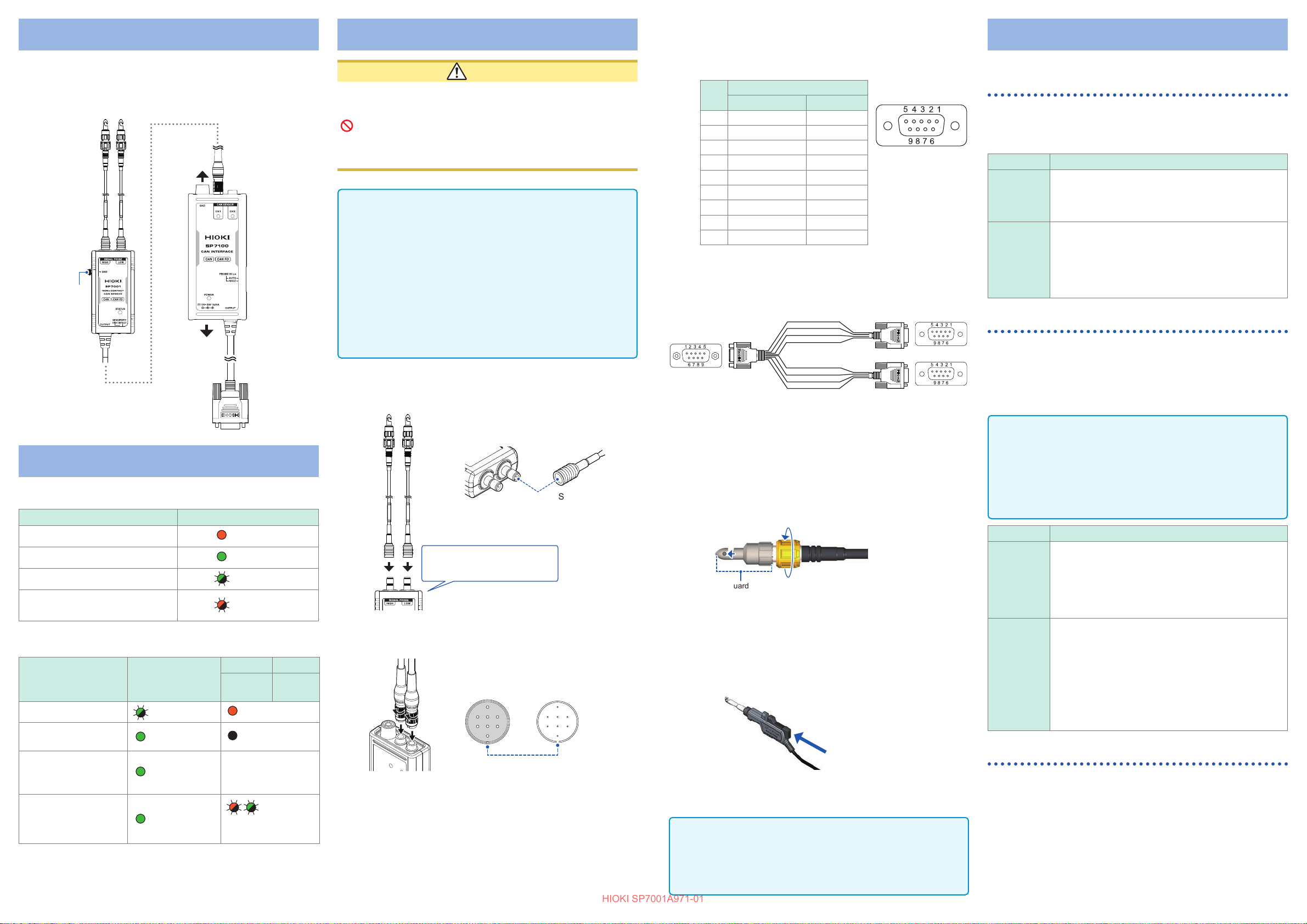
Connection example:
6
“2.7 Connecting
the Signal Probes
to the CAN bus”
“2.2 Connecting
the Signal Probes”
“2.4
Connecting
the Ground
Terminal”
3
“2.3 Connecting
the Non-Contact CAN
Sensor”
2
1
3
“2.4 Connecting
the Ground
Terminal”
5
“2.6 Supplying
Power”
4
“2.5 Connecting
the CAN Interface”
LED lighting/ashing specications
SP7001/SP7002 Non-Contact CAN Sensor
Product status STATUS LED
Self-test error (failure)
Signal not detected
Signal detected
Probe high/low reverse connection
warning
SP7100/SP7150 CAN Interface
Product status POWER LED
Self-test error (failure)
CAN sensor not
connected
CAN sensor connected
Output bus error
detection
Flashing green Steady red
Steady green Unlit
Steady green
Steady green
Steady red
Steady green
Flashing green
Flashing red
SP7100 SP7150
CH1, CH2
LED
Reects CAN
Sensor’s STATUS
LED.
alternating red/
green
STATUS
LED
Quickly
Detection Procedure
CAUTION
Do not connect the probes to bare conductors with
exposed metal or cables with damaged insulation. Do
not allow the tips of the probes to come into contact with
any energized part.
Doing so may damage the equipment you are using (the
vehicle) or cause it to malfunction.
IMPORTANT
The Signal Probe’s connector incorporates a locking mechanism.
Always use the probe with the connector in the locked state to
ensure signals can be properly detected and to prevent damage
to the connector.
Leave the Signal Probe connected to prevent deterioration of
•
the Signal Probe and Non-Contact CAN Sensor’s connector’s
contacts and to keep out dirt.
• Any dirt on the cable under test could aect signal detection.
Remove any dirt before axing (connecting) the Signal Probe.
• Do not connect both the SP9200 and SP9250 to the same NonContact CAN Sensor. Doing so may increase susceptibility to
the eects of noise.
Connect the Signal probe to the the Non-Contact
1
CAN Sensor’s signal probe connector.
Example: SP9200 Signal Probe
SP7001 or SP7002
Signal Probe connector
Insert until you hear a clicking
sound to lock the connector.
SP7001/SP7002 Non-Contact CAN Sensor
Connect the Non-Contact CAN Sensor to the CAN
2
Interface.
SP7001’s or SP7002’s
Example: SP7100 CAN Interface
Connect the CAN Interface’s ground terminal to the
3
output connector
Align slits
vehicle’s ground.
If connecting the CAN interface’s ground terminal to the
ground cannot reduce the noise, connect the Signal probe’s
ground terminal to the vehicle’s ground.
SP9200 connector
with lock
SP7001 or SP7002P7100 or SP7150
Connect the CAN Interface’s CAN signal output
4
connector to the CAN interface-equipped device
with which you wish to use it.
Pin assignment of CAN signal output connector
Pin
1 CH2 CAN Low N.C.
2 CH1 CAN Low CAN Low
3 CH1 GND GND
4 N.C. N.C.
5 Shield Shield
6 CH2 GND N.C.
7 CH1 CAN High CAN High
8 CH2 CAN High N.C.
9 N.C. N.C.
Assignment
SP7100 SP7150
SP9900 Split Cable (dedicated option for SP7100)
If the input interface provided by the device you plan to use does not
support 2-channel input, use the SP9900 Split Cable.
CH1 CAN Low
2 2
CH1 GND
MALE
CH1/CH2
Supply power to the CAN Interface
5
Connect the Signal Probe to the cable under test.
6
When using the SP9200 Signal Probe:
Rotate the grip of Signal Probe to press the cable
1.
under test against the detection electrode.
Connect the Signal Probe connected to the terminal
labeled
Probe to the CAN_L line.
Tighten the grip until it no longer rotates.
2.
The probe contains a built-in spring that supports the cable
under test.
When using the SP9250 Signal Probe:
Press the open/close lever to open the guard hook.
1.
Clamp the hook around the cable whose signals you
2.
wish to detect and release the open/close lever.
The probe will be secured to the cable under test.
HIGH
Guard hook
3 3
CH1 CAN High
7 7
Shield
5 5
Shield
2
3
7
5
CH2 CAN Low
1
6
CH2 GND
CH2 CAN High
8
5
to the CAN_H line and the other Signal
FEMALE
CH1
CH2
IMPORTANT
• Position the probe so that the cable under test is in contact with
the back of the detection electrode.
• Proper detection will be impossible if the cable under test is
positioned too shallowly or angled in the guard hook.
Functionality
Switching the Non-Contact CAN Sensor’s Signal
Detection Sensitivity
This section describes how to switch the Non-Contact CAN Sensor’s
signal detection sensitivity
for most applications. Select
CAN signal level and cable eects.
Setting Description
The DEFAULT setting represents the normal mode.
DEFAULT
HIGH
It is recommended to use DEFAULT mode since
it delivers the optimal level of vibration and noise
resistance.
The HIGH setting represents high-sensitivity mode.
Use this mode when you encounter detection errors
due to the low signal levels detected by the Signal
Probes.
The product is more susceptible to vibrations and
various types of noise when used in this mode.
SENSITIVITY
(
HIGH
as necessary depending on the
). Use the
Probe Setting Function (Automatic Polarity Selection)
The probe setting function automatically selects the Signal Probe’s
polarity.
It is a convenient function that automatically switches the sensor
input when the SP9200 or SP9250 signal probes have been
connected in reverse to the Non-Contact CAN Sensor input label
(HIGH/LOW).
IMPORTANT
When performing rigorous evaluations, for example in bus testing
that includes verication of wiring consistency, connect the high
and low Signal Probes to the CAN bus’s high and low lines and
use xed input polarity (
In automatic input polarity mode (
guaranteed under all conditions.
Setting Description
The FIXED setting represents xed input polarity
mode.
FIXED
AUTO
If the Non-Contact CAN Sensor detects that the
Signal Probes are connected to the CAN bus in
reverse, it will indicate this state with the
LED, which will ash red.
The AUTO setting represents automatic input
polarity mode.
If the Non-Contact CAN Sensor detects that the
Signal Probes are connected to the CAN bus in
reverse, it will switch the high and low detected
signals via its internal circuitry.
This function will operate in approximately 2
seconds as long as the CAN bus load factor is
approximately 5% or greater.
FIXED
) mode.
AUTO
), correct detection is not
Output Bus Error Detection Function
This function determines that an output error has occurred when the
SP7100 or SP7150 CAN Interface is unable to output a proper CAN
signal to the bus connected to the CAN signal output connector.
The SP7100 CAN interface output does not have CAN signal
arbitration functionality. CAN communications signals detected by
the Non-Contact CAN Sensor are output without modication.
The output bus error detection function operates when the NonContact CAN Sensor is connected properly to the CAN_H and
CAN_L lines (as per the labels on the Non-Contact CAN Sensor
inputs).
DEFAULT
STATUS
setting
 Loading...