

ST5680
HIOKI ST5680A966-00
Communications Command
DC HIPOT TESTER
Instruction Manual
Dec. 2022 Edition 1
ST5680A966-00 22-12H
This manual explains the communication commands for Model ST5680 DC Hipot
Tester.
Please refer to the instruction manual for Model ST5680 for details regarding
command settings.
Although all reasonable care has been taken in the production of this manual,
should you nd any points which are unclear or in error, please contact your local
distributor or the HIOKI International Sales Department at os-com@hioki.co.jp.
In the interest of product development, the contents of this manual may be subject
to revision without notice.
Unauthorized copying and replication of the contents of this instruction manual are
strictly prohibited. All Rights Reserved.
EN

1
Contents
HIOKI ST5680A966-00
1 Introduction ............................................................................................................................................. 2
Message Format ..................................................................................................................................... 2
Output Queue and Input Buffer ............................................................................................................. 6
Status Byte Register .............................................................................................................................. 7
Event Resisters ....................................................................................................................................... 9
Response Format ................................................................................................................................. 14
Measured Value in case of Measurement Error ................................................................................ 18
Item to return to Initial State ................................................................................................................ 18
Errors during Communication ............................................................................................................ 18
2 Message List .......................................................................................................................................... 19
3 Message Reference............................................................................................................................... 28
Standard Commands ........................................................................................................................... 29
Event Register ....................................................................................................................................... 33
Tes t M o de .............................................................................................................................................. 34
Withstand Voltage Test ........................................................................................................................ 35
Insulation Resistance Test .................................................................................................................. 43
Program Test ......................................................................................................................................... 49
BDV Measurement ................................................................................................................................ 56
Test Common ........................................................................................................................................ 62
Panel Memory ....................................................................................................................................... 66
Data Memory ......................................................................................................................................... 70
EXT. I/O ................................................................................................................................................... 72
System ................................................................................................................................................... 74
Run ......................................................................................................................................................... 81
Measured Value Output ........................................................................................................................ 82
On-Screen Display ................................................................................................................................ 99
Screen Saving ..................................................................................................................................... 103
File Saving ........................................................................................................................................... 104
Communication ................................................................................................................................... 112
Compatibility Mode............................................................................................................................. 118
4 List of Initialization Items ................................................................................................................... 119
5 Sample programs ................................................................................................................................ 123
Created in Visual C#
6 Device Compliance Requirements [GP-IB] ...................................................................................... 133
®
......................................................................................................................... 123
2
1 Introduction
HIOKI ST5680A966-00
When creating a program, using the command monitor function displays commands and responses on the
measurement screen. For command monitor function, please see the instruction manual of this instrument.
Various messages are provided to control the instrument in the interface.
Messages include program messages sent from a computer or other controller to the instrument and response
messages sent from the instrument to the controller.
Program Messages
Controller Instrument
Response Messages
Communication commands are classified as follows.
Program Messages
Communication
commands
Response Messages
Command Messages
Query Messages
Commands with data should be entered in the specified data format.
Message Format
Program Messages
Program messages can be divided into command and query messages.
(1) Command Messages
Instruction to control equipment such as equipment setting and reset
(Example) Instruction to set momentary out function
:SYSTem:MOMentary:OUT 1
Header section Space Data part
(2) Query Messages
Instructions to query operation results, measurement results, or
equipment setting status
(Example) Instruction to query momentary out function
:SYSTem:MOMentary:OUT?
Header section Question mark
See “Header” (p. 3), “Separator” (p. 4), and “Data part” (p. 5).

3
HIOKI ST5680A966-00
Response Messages
Receives a query message and creates it when the syntax is checked.
If any error occurs when a query message is received, no response message will be created to match that query
message.
Command Syntax
Command names are chosen for instructions that are as understandable as possible to the function to be
executed, and yet can be shortened. The mandate name itself is called the “long form” and its shortened form
is called the “short form”. This document describes the part of the short form as a large character and the rest
in small letters, but accepts either large or small characters.
START OK (Long form)
STAR OK (Short form)
STA Error
The response message from the instrument is returned in a large character long form.
Headers
A header is always required for program messages.
(1) Command Program Header
There are three types: simple command type, compound command type, and Standard Command type.
• Simple Command type Header
• Combined Command type Header
• Standard Command type Header
(2) Query Program Header
Used to query the result of an action to a device command, the result of a measurement, or the current device
setting status.
As in the example below, the question mark
:S TATe ?
:SYSTem:MOMentary:OUT?
Header consisting of a single word beginning with an English letter
:STOP
Header consisting of multiple simple command type headers separated by colon (:)
:SYSTem:MOMentary:OUT
A header starting with an asterisk ‘software’ indicating that it is a Standard Command (provided by IEEE
488.2)
∗RST
(?) is attached at the end of the program header.

4
HIOKI ST5680A966-00
Message Terminators
The instrument accepts the following as a message terminator (delimiter).
[RS-232C/USB/LAN]
• CR
• LF
• CR+LF
[GP-IB]
•
• LF
• CR+LF
• EOI
• EOI with CR
• EOI with LF
• EOI with CR+LF
In addition, the following can be selected as terminators for response messages, depending on the interface
settings.
For settings, see “Setting for message terminators” (p.113, p.113 , p.11 5 , p.116).
CR
[RS-232C/USB/LAN]
• CR
• LF
• CR+LF
[GP-IB]
•
• EOI with LF
• EOI with CR+LF
EOI with CR
Separators
(1) Message Unit Separator
Multiple messages can be written on a single line by connecting each with a semicolon (;).
:SYSTem:MOMentary:OUT 1;∗IDN?
If the message is described continuously, if an error occurs in the sentence, message from after that to the
•
message terminator will not be executed.
(2) Header Separator
Messages with headers and data are separated into the header and data parts by using a blank (ASCII
code 20h).
:SYSTem:MOMentary:OUT 1
(3) Data Separator
Messages with multiple data separate between data by comma (,).
:SYSTem:DATE 22,1,1

5
HIOKI ST5680A966-00
Data Formats
The instrument uses “character data,” “decimal numeric value data,” and “string data” in the data section, and is
more used to commands.
(1) Character Data
It is data that always starts with English letters and consists of English letters and numbers. Character data
accepts both large and small characters, but response messages from this instrument are always returned in
large letters. In the Command data part <1/0/ON/OFF >, for 0 is OFF, 1 behaves similar to ON, query response
OFF is 0, ON is 1.
:SYSTem:MOMentary:OUT OFF
(2) Decimal Numeric Value Data
Numerical data formats include NR1, NR2, and NR3 formats. Each accepts both signed and unsigned numerical
values. For unsigned numerical value treat as a positive numerical value. If the precision of the numerical value
exceeds the handling range of the instrument, it is rounded off.
• NR1 integer data (Example: +12, -23, 34)
• NR2 decimal data (Example: +1.23, -23.45, 3.456)
• NR3 floating point exponential display data (Example: +1.0E-2、-2.3E+4))
A format that includes all three of these types is called an “NRf format.”
For response data, the format is specified for each command and sent in that format.
:CONFigure:WITHstand:VOLTage:LEVel 11
:MONitor:VOLTage?
(3) String Data
[GP-IB]
8.400E+03
String data surrounds the front and rear with a quota mark.
•
• Data consisting of 8 bit ASCII characters.
• Characters that can not be handled by this instrument are an error.
• Quotation mark, transmission from this instrument is only double quote (") but reception accepts both double
quote and single quote (').
:FILE:NAME "D ATA "
This instrument is not fully compatible with IEEE 488.2. As much as possible, use the data shown in the
reference.

6
HIOKI ST5680A966-00
Omission of Compound Command type Header
What the leading parts of the compound commands are common (example: :SYSTem:BEEPer:
VOLume:PASS
command (example:
This common part is called the “current path,” and until it is cleared, subsequent commands are analyzed as if the
“current path” is omitted.
and :SYSTem:BEEPer:VOLume:FAIL) can omit the common part of the
:SYSTem:BEEPer:VOLume) only if they continue to describe them.
The following example illustrates the use of the current path.
Usual notation
:SYSTem:BEEPer:VOLume:PASS 1; :SYSTem:BEEPer:VOLume:FAIL 5
Abbreviated notation
:SYSTem:BEEPer:VOLume:PASS 1; FAIL 5
This is the current path and can be omitted in the following commands.
The current path can be a power-up, a reset by keystroke, or a colon (:) at the beginning of the command and clears
on detection of message terminators.
Messages of the Standard Command type can be executed regardless of the current path. It also does not affect
the current path.
Simple and compound command type headers do not need to be prefixed with a colon (:). However, to prevent
confusion with abbreviations and malfunctions, we recommends prefixing the command with (:).
Output Queue and Input Buffer
Output Queue
The response message is stored in the output queue and cleared when the controller reads the data. Otherwise,
the output queue is cleared when
• Power-on
• Device clear [GP-IB].
• Query of error
Input Buffer
The capacity of the input buffer is 1460 bytes.
When the buffer runs out of space, the operation stops until that space becomes available.
NOTES: The length of a single line of command should be less than 1460 bytes.
7
bit7 bit6
bit5 bit4 bit3 bit2 bit1 bit0
SRQ
MSS
& →
Disjunction
← & & & & &
&
bit7 bit6
bit5 bit4 bit3 bit2 bit1 bit0
Service Requests
(SRER)
HIOKI ST5680A966-00
Status Byte Register
[GP-IB]
This instrument uses the status model specified in IEEE 488.2 for the part related to serial polling by the Service
Request function. An event is a matter that causes a Service Request to occur.
Standard Event Status Register information
Service Request Information on output queue data Information on Event Status Register 0
generation of SRQ Error occurrence information
Unused
↓ ↑ ↓ ↓ ↓ ↓ ↓ ↓
↑ ↑ ↑ ↑ ↑ ↑ ↑
Unused 0
ESB MAV Unused ERR Unused ESB0
ESB MAV Unused ERR Unused ESB0
Conceptual diagram of Service Request generation
Status Byte
Register (STB)
Enable Register
The Status Byte Register is set to the event register and output queue information. From among this information, the
Service Request enable register allows you to select what you need. If the selected information is set, bit 6 (MSS
Master Summary Status bit) of the Status Byte Register is set, generating an SRQ (Service Request) message,
which in turn generates a Service Request.
NOTES: SRQ (Service Request) is a GP-IB only function.
However, STB (Status Byte Register) information can also be obtained via
RS-232C/USB/LAN by using the ∗STB? command.
STB (Status Byte Register) information can be obtained by using the
∗STB? command.
[RS-232C/USB/LAN]
RS-232C/USB/LAN does not have the ability to generate Service Requests. However, it is possible to set SRER and
read STB.

8
bit7
Unused
When a
Represents the logical OR of the other bits in the Status Byte
Register (STB).
Standard
Represents the logical OR of the
It is cleared when the
output by the *ESR? command.
Message
It is set to “1” when there is a message in the output queue.
bit3
Unused
Error bit
If there is error information, it is set to
It is reset when error information is output by
the :SYSTem:ERRor? command.
bit1
Unused
Event summary (logical OR) bit 0
Represents the logical OR of Event Status Register 0.
HIOKI ST5680A966-00
Status Byte Register (STB)
The Status Byte Register is an 8-bit register that is output from the instrument to the controller when performing
serial polls. The MSS bit is set to “1” when any bit in the Status Byte Register changes from “0” to “1” among the
bits set to be available in the Service Request enable register. At the same time, the SRQ bit is set to “1” and a
Service Request is generated.
The SRQ bit is always synchronized with the Service Request and is read only when it is serially polled and cleared
at the same time. The MSS bit is only read by the
∗CLS command, for example.
∗STB? query, but is not cleared until the event is cleared by the
SRQ
bit6
MSS
bit5 ESB
bit4 MAV
bit2 ERR
bit0 ESB0
Service Request is sent out, it is set to “1”.
Event summary (logical OR) bit
Standard Event Status Register.
Standard Event Status Register value is
-available
“1”.
Service Request Enable Register (SRER)
The Service Request Enable Register is a register that allows each bit to be “1” the corresponding bits in the Status
Byte Register become available.

9
HIOKI ST5680A966-00
Event Resisters

10
Power-On Flag
It is set to
restored from a power failure.
Not used in this unit.
User Request
Command error (Ignore commands up to the message
terminator)
It is set to
received command.
•
•
•
• When a command that does not exist in this instrument is received
Execution error
It is set to
some reason.
•
•
• If another function is running and cannot be performed
Equipment-Dependent Error
It is set to
reasons other than command error, query of error, or execution error.
Query
It is set to
queue.
•
• If data in the output queue is lost
Not used in this unit.
Request Control
Completion of Operation
•
•
completed
HIOKI ST5680A966-00
Standard Event Status Register (SESR)
The Standard Event Status Register is an 8-bit register. When any bit in the Standard Event Status Register is set
to “1” among the bits set to be available in the Standard Event Status Enable Register, bit 5 (ESB) in the Status
Byte Register is set to “1”.
See “Standard Event Status Register (SESR) and Standard Event Status Enable
Register (SESER)”
(p.11)
The contents of the Standard Event Status Register are cleared when:
• When the ∗CLS command is executed
• When an event register query is executed (∗ESR?)
• When the power is turned on again
bit7 PON
bit6
bit5 CME
bit4 EXE
bit3 DDE
URQ
(Unused)
“1” when the power is turned on or when the power is
“1” when there is a grammatical or semantic error in the
Errors in the program header
If the number of data is different from that specified
If the data format is different from that specified
“1” when the received command cannot be executed for
If the specified data is outside the setting range
If the specified data cannot be set
“1” when the command could not be executed due to
Error (Clears the output queue)
“1” when an error occurs in processing related to the output
bit2 QYE
When data overflows the output queue
bit1
bit0 OPC
RQC
(Unused)
When the ∗OPC command is executed
When the operation of all messages up to the *OPC command is

11
Status Byte Register (STB)
SRQ
MSS
Standard Event Status Register (SESR)
PON
URQ
CME
EXE
DDE
QYE
RQC
OPC
Standard Event Status Enable Register (SESER)
HIOKI ST5680A966-00
Standard Event Status Enable Register (SESER)
The Standard Event Status Enable Register enables the corresponding bit in the Standard Event Status Register
by setting each bit to “1”.
Standard Event Status Register (SESR) and Standard Event Status Enable Register (SESER)
bit6 bit5 bit4
ESB M AV
bit7 bit6 bit5 bit4 bit3 bit2 bit1 bit0
↑
Disjunction ← & & & & & & & &
PON URQ CME EXE DDE QYE RQC OPC
↓ ↓ ↓ ↓ ↓ ↓ ↓ ↓
↑ ↑ ↑ ↑ ↑ ↑ ↑ ↑
bit7 bit6 bit5 bit4 bit3 bit2 bit1 bit0

12
Unique Event Status Register 0 (ESR0)
bit7 - Unused
bit6 - Unused
bit5 - Unused
bit4 - Unused
bit3
EOM
Test completed
bit2
LFAIL
LOWER FAIL judgment
bit1
UFAIL
UPPER FAIL judgment
bit0
PASS
PASS judgment
Status Byte Register (STB)
bit2 bit1 bit0
ESB0
Event Status Register 0 (ESR0)
bit7 bit6 bit5 bit4 bit3 bit2 bit1 bit0
Disjunction & & & & & & & &
bit7 bit6 bit5 bit4 bit3 bit2 bit1 bit0
Event Status Enable Register 0 (ESER0)
Register
Read
Write
*STB?
-
*SRE?
*SRE
*ESR?
-
Standard Event Status Enable Register
*ESE?
*ESE
:ESR0?
-
:ESE0?
:ESE0
HIOKI ST5680A966-00
Unique Event Status Register (ESR0)
A single Event Status register is provided to manage the instrument's events. The Event Status register is an 8-bit
register.
If any bit in the Event Status register is set to “1” among the bits set to be available in the Event Status enable
register, the following occurs.
• For Event Status Register 0: Bit 0 (ESB0) of the Status Byte Register (STB) is “1”.
The contents of Event Status register 0 are cleared when:
• When the CLS command is executed
• When an event register query is executed (:ESR0?)
•
When the power is turned on again
Event Status Register 0 (ESR0) and
Unique Event Status Enable Register 0 (ESER0)
↓ ↓ ↓ ↓ ↓ ↓ ↓ ↓
↑ ↑ ↑ ↑ ↑ ↑ ↑ ↑
Unused Unused Unused Unused
Unused Unused Unused Unused
Read/Write Each Register
Status Byte Register
Service Request Enable Register
EOM LFA IL UFAIL PASS
EOM LFA IL UFAIL PASS
Standard Event Status Register
Event Status Register 0
Event Status Enable Register 0

13
Commands
Contents
GTL
Go To Local
The remote state is released and the local state is set.
LLO
Local Lock Out
All keys, including local keys, are rendered inoperable.
DCL
Device CLear
Clears the input buffer and output queue.
Device Clear
Trigger
HIOKI ST5680A966-00
GP-IB Commands
The interface function allows the following commands to be used.
SDC Selected
GET Group Execute
Clears the input buffer and output queue.
When in READY state, the test is started.
14
Positive value
□ □ □ . □ □ □ . □ □ .
□
D C
Positive value
□ □ □ □
□ □ □
□ □
□
Positive value
□ □ □ . □ □ □ □ □ . □ □ □ □ . □ □
□
Positive value
□ □ □ □ □ □ □ □ □
Negative value
- □ □ □ □ - □ □ □ - □ □
Positive
value
□ □
□
Positive value
□ □ □ □ □ . □ □ .
□
HIOKI ST5680A966-00
Response Format
• Interval time (withstand voltage test, insulation resistance test), remaining test time (withstand voltage test, insulation
resistance test), elapsed test time (withstand voltage test, insulation resistance test, BDV measurement)
Units: s, NR2 numerical format
• Test frequency (withstand voltage test, BDV measurement)
Test voltage (withstand voltage test), initial voltage (BDV measurement), end voltage (BDV measurement), voltage
step (BDV measurement), median breakdown voltage (BDV measurement), average breakdown voltage (BDV
measurement)
Unit: V, NR1 numerical format
• Dielectric breakdown voltage standard deviation (BDV measurement)
Units: V, NR2 numerical format
• Test voltage (insulation resistance test)
Unit: V, NR1 numerical value format
• Start voltage (withstand voltage test)
Unit: %, NR1 numerical value format
• Test time (withstand voltage test, insulation resistance test), voltage rise time (withstand voltage test, insulation
resistance test), voltage fall time (withstand voltage test, insulation resistance test)
Units: s, NR1 or NR2 numerical value format
15
Positive value
□ □ . □ □ .
□
Positive value
□ □ □ . □ □ □ . □ □ □ . □ □
□
value
□ □
□
Positive value
□ □ □ □ □ □ □ □ □ □ □ □ . □ □ □ . □ □ □ . □ □ □ □ . □ □ □ □ □ . □ □ □ □
□
Positive value
□ □ . □ □ □ . □
□
Positive value
□ □ □ □ □ □ □ □ □ □ □ . □ □
Positive value
□ □ □ □ □
□
HIOKI ST5680A966-00
• Judgment waiting time (withstand voltage test, insulation resistance test)
Units: s, NR2 numerical value format
• Test upper limit (withstand voltage test), test lower limit (withstand voltage test), current upper limit reference value
(BDV measurement)
Units: mA, NR2 numerical value format
• Upper current limit of ARC discharge detection function (withstand voltage test, BDV measurement)
Positive
Unit: %, NR1 numerical value format
• Test upper limit (insulation resistance test), test lower limit (insulation resistance test)
Units: MΩ, NR1 or NR2 numerical value format
• Distance between electrodes (BDV measurement)
Units: mm, NR2 numerical value format
• Voltage rise rate (BDV measurement)
Units: V/s, NR1 or NR2 numerical value format
• Voltage holding time for each step (BDV measurement)
Units: s, NR1 numerical value format
16
Positive value
□ □ □ . □ □ □ □ □ . □ □ □ □ . □ □
□
Positive value
□ □ □ . □ □ □ □ □ . □ □ □ □ . □ □
□
Positive value
□ □ □ . □ □ □ . □ □ .
□
W I R B D V
R A T E S T E
P
□ □ □ □ - □ □ - □ □ □ □ : □ □ : □ □
P A S S U F A I L L F A I L U L F A I L O F F
P A S S F A I
L
N O N E P A S S F A I
L
Positive
value
□
HIOKI ST5680A966-00
• Median dielectric breakdown strength (BDV measurement), average dielectric breakdown strength (BDV
measurement)
Units: kV/mm NR2 numerical value format
• Dielectric breakdown voltage standard deviation (BDV measurement)
Units: V/mm NR2 numerical value format
• Judgment threshold value for contact check (withstand voltage test, insulation resistance test)
Units: nF, NR2 numerical value format
• Test mode
• Te s t method (BDV measurement)
• Test start date and time
• Judgment result
• Test results (programmed test mode)
• Contact check judgment result
• Timer type
NR1 numerical value format
17
3 0 0 u A 3 m A 3 0 m A 3 0 0 m A N O N E
1 0 0 k o h m 1 M o h m 1 0 M o h m 1 0 0 M o h m 1 G o h m 1 0 G o h m 1 0 0 G o h m N O N E
Positive value
□ . □ □ □ E ± □
□
Negative value
- □ . □ □ □ E ± □
□
Positive value
□ . □ □ □ E ± □
□
Positive value
□ . □ □ □ E ± □
□
Positive value
□ . □ □ □ E ± □
□
Positive value
□ . □ □ □ E ± □
□
Positive value
□ □ □ □ □
□
HIOKI ST5680A966-00
• Measuring range (withstand voltage test)
• Measuring range (insulation resistance test)
• Voltage measurements (withstand voltage test, insulation resistance test)
Unit: V, NR3 numerical value format
• Measured voltage (BDV measurement)
Unit: V, NR3 numerical value format
• Measured current (withstand voltage test, insulation resistance test, BDV measurement), offset cancellation
correction value (withstand voltage test)
Unit: A, NR3 numerical value format
• Resistance measurements (withstand voltage test, insulation resistance test), offset cancellation correction values
(insulation resistance test)
Unit: Ω, NR3 numerical value format
• Contact check correction value (withstand voltage test, insulation resistance test), contact check measurement value
(withstand voltage test, insulation resistance test)
Unit: F, NR3 numerical value format
• Number of points (measured value voltage, measured value current, measured value resistance)
NR1 numerical value format

18
turned on
(GP-IB only)
Device-Specific Features (test conditions,
correction values, etc.)
Output Queue
✓
-
-
Input Buffer
✓
-
-
Status Byte Register
✓
-
Event Register
*3
-
-
Enable Register
✓
- - -
Current Path
✓
-
-
HIOKI ST5680A966-00
Measured Value in case of Measurement Error
• Overflow
1.000E+24 or the maximum value of the measurement range
• Underflow
0.000E+00
• Auto range no judgment
3.333E+33
*1. Depending on the setting for the measured value at the time of range-over
*2. Waveform data and trend data are not dependent on the setting for the measured value at the time of
range-over 1.000E+24
Item to return to Initial State
item
When the
power is
*1 *2
Reset the
instrument
*RST
command
Device
clear
*CLS
command
-
✓
✓
✓
✓
✓
✓
*1. Clear MAV bit (bit4) only.
*2. Clear all bits except the MAV bit.
*3. Except for the PON bit (bit7).
Errors during Communication
Executing a message in the following cases, it will result in an error.
• Command error
If the spelling of the message is incorrect
If the data portion of the command or query is in the wrong format
• Query of error
When the controller is unable to send a response message because the instrument is in a state where it cannot
receive the message
• Run error
When set with data other than the specified character or numerical value data
✓
✓
✓
- -
✓
✓
*1
✓
✓
✓
✓
*2

19
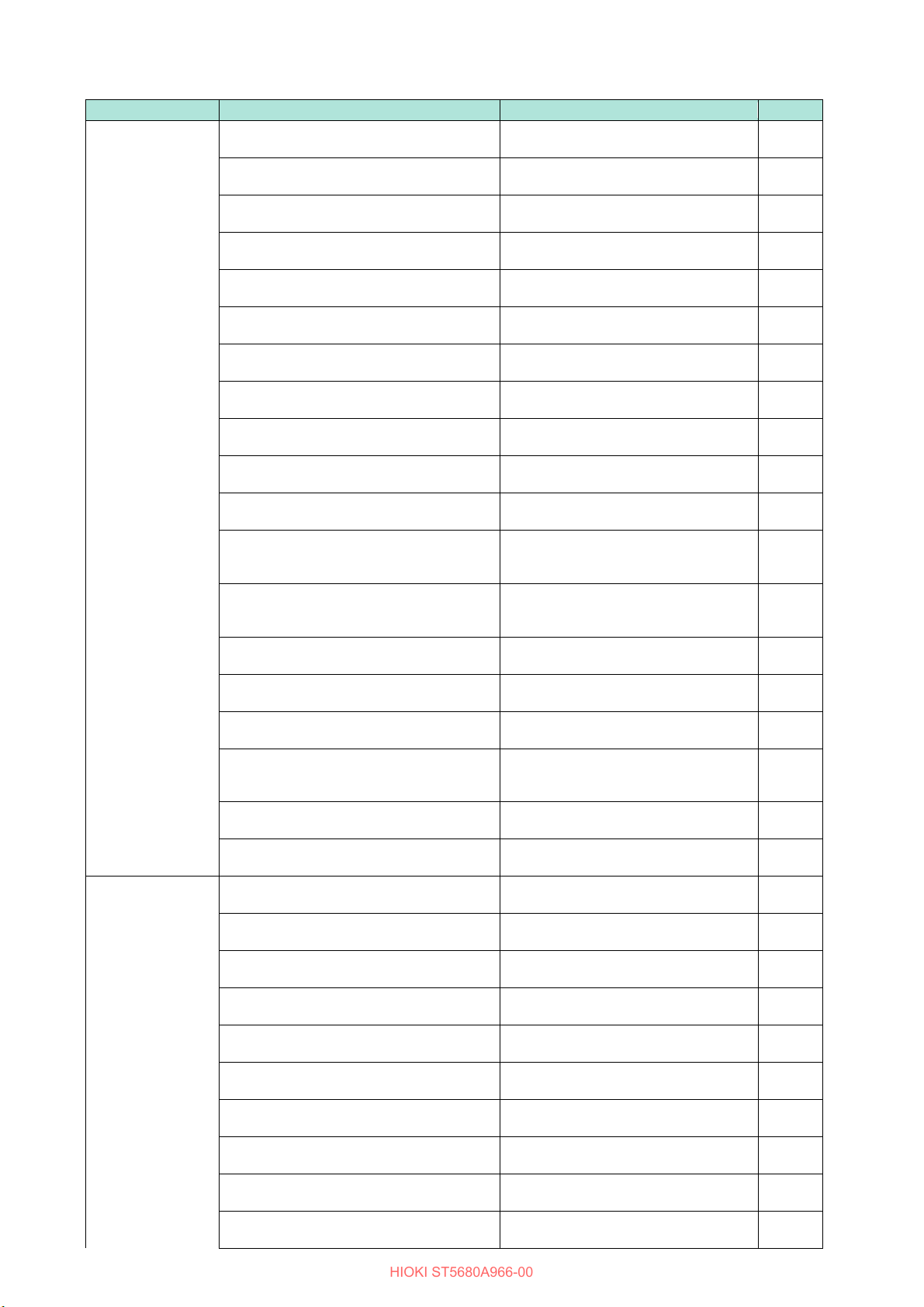
Classification
Communication commands
Feature
Reference
Standard
*CLS
Clear Event Status Register
p. 29
*IDN?
Inquiry of device ID (identification code)
p. 29
*OPC
After all running operations are
completed, set the Operation Complete
bit in the Standard Event Status
Register (SESR) to 1.
p. 29
*OPC?
Respond 1 after all running operations
are completed.
p. 29
*OPT?
Query of installed options
p. 30
*RST
Initialization of equipment
p. 30
*TRG
Start of test
p. 30
*TST?
Run self-test and query of result
p. 30
*WAI
After command processing is
completed, subsequent commands are
executed.
p. 31
*ESE
Standard Event Status Enable Register
(SESER) setting
p. 31
*ESE?
Standard Event Status Enable Register
(SESER) query
p. 31
*ESR?
Standard Event Status Register (SESR)
query
p. 31
*SRE
Service Request Enable Register
(SRER) setting
p. 32
*SRE?
Service Request Enable Register
(SRER) query
p. 32
*STB?
Status Byte Register (STB) query
p. 32
Event Register
:ESE0
Event Status Enable Register 0
(ESER0) setting
p. 33
:ESE0?
Event Status Enable Register 0
(ESER0) query
p. 33
:ESR0?
Event Status Register 0 (ESR0) query
p. 33
Te s t Mode
:MODE
Test mode setting
p. 34
:MODE?
Test mode query
p. 34
Withstand Voltage
:CONFigure:WITHstand:STEP:INTerval
Setting for the interval time for withstand
voltage test
p. 35
:CONFigure:WITHstand:STEP:INTerval?
Query of interval time for withstand
voltage test
p. 35
:CONFigure:WITHstand:VOLTage:LEVel
Setting for test voltage for withstand
voltage test
p. 35
:CONFigure:WITHstand:VOLTage:LEVel?
Query of test voltage for withstand
voltage test
p. 35
:CONFigure:WITHstand:VOLTage:STARt
Setting for the starting voltage for
withstand voltage test
p. 36
:CONFigure:WITHstand:VOLTage:STARt?
Query of the starting voltage for
withstand voltage test
p. 36
:CONFigure:WITHstand:TIMer
Setting for the test time for withstand
voltage test
p. 36
:CONFigure:WITHstand:TIMer?
Query of the test time for withstand
voltage test
p. 36
:CONFigure:WITHstand:RISE:TIMer
Setting for the voltage rise time for
withstand voltage test
p. 37
:CONFigure:WITHstand:RISE:TIMer?
Query of the voltage rise time for
withstand voltage test
p. 37
:CONFigure:WITHstand:FALL:TIMer
Setting for the voltage drop time for
withstand voltage test
p. 37
HIOKI ST5680A966-00
2 Message List
Commands
Test
20
Classification
Communication commands
Feature
Reference
:CONFigure:WITHstand:FALL:TIMer?
Query of the voltage drop time for
withstand voltage test
p. 37
:CONFigure:WITHstand:JUDGment:DELay
Setting for the judgment waiting time for
withstand voltage test
p. 38
:
CONFigure:WITHstand:JUDGment:DELay?
Query of judgment waiting time for
withstand voltage test
p. 38
:CONFigure:WITHstand:LIMit:UPPer
Setting for the upper test limit for
withstand voltage test
p. 38
:CONFigure:WITHstand:LIMit:UPPer?
Query of the upper test limit for
withstand voltage test
p. 38
:CONFigure:WITHstand:LIMit:LOWer
Setting for the lower test limit for
withstand voltage test
p. 39
:CONFigure:WITHstand:LIMit:LOWer?
Query of the lower test limit for
withstand voltage tests
p. 39
:
CONFigure:WITHstand:LIMit:LOWer:STATe
ON/OFF setting of the lower test limit for
withstand voltage test
p. 39
:CONFigure:WITHstand:LIMit:LOWer:STATe?
Query of ON/OFF of the lower test limit
for withstand voltage test
p. 39
:CONFigure:WITHstand:ARC:STATe
Setting for the ARC discharge detection
function for withstand voltage test
p. 40
:CONFigure:WITHstand:ARC:STATe?
Query of the ARC discharge detection
function for withstand voltage test
p. 40
:CONFigure:WITHstand:ARC:LIMit
Setting for the upper current limit of the
ARC discharge detection function for
withstand voltage test
p. 40
:CONFigure:WITHstand:ARC:LIMit?
Query of the upper current limit value of
the ARC discharge detection function for
withstand voltage test
p. 41
:CONFigure:WITHstand:OFFSet:CANCel
Setting for the offset cancel function for
withstand voltage test
p. 41
:CONFigure:WITHstand:OFFSet:CANCel?
Query of the offset cancel function for
withstand voltage test
p. 41
:CONFigure:WITHstand:OFFSet:CANCel:V
ALue?
Query of offset cancellation correction
value for withstand voltage test
p. 41
:CONFigure:WITHstand:CONTactcheck:TH
Setting for the threshold value for
judging contact checks in withstand
voltage test
p. 42
:CONFigure:WITHstand:CONTactcheck:TH
Reshold?
Query of the threshold value for judging
contact checks in withstand voltage test
p. 42
:CONFigure:WITHstand:CONTactcheck:VA
Lue?
Query of the contact check correction
value for withstand voltage test
p. 42
Insulation
:CONFigure:INSulation:STEP:INTerval
Setting for the interval time for insulation
resistance test
p. 43
:CONFigure:INSulation:STEP:INTerval?
Query of interval time for insulation
resistance test
p. 43
:CONFigure:INSulation:VOLTage:LEVel
Setting for test voltage for insulation
resistance test
p. 43
:CONFigure:INSulation:VOLTage:LEVel?
Query of test voltage for insulation
resistance test
p. 43
:CONFigure:INSulation:TIMer
Setting for the test time for insulation
resistance test
p. 44
:CONFigure:INSulation:TIMer?
Query of the test time for insulation
resistance test
p. 44
:CONFigure:INSulation:RISE:TIMer
Setting for the voltage rise time for
insulation resistance test
p. 44
:CONFigure:INSulation:RISE:TIMer?
Query of the voltage rise time for
insulation resistance test
p. 44
:CONFigure:INSulation:FALL:TIMer
Setting for the voltage drop time for
insulation resistance test
p. 45
:CONFigure:INSulation:FALL:TIMer?
Query of the voltage drop time for
insulation resistance test
p. 45
HIOKI ST5680A966-00
Reshold
Resistance Test

21
Classification
Communication commands
Feature
Reference
:CONFigure:INSulation:JUDGment:DELay
Setting for the judgment waiting time for
insulation resistance test
p. 45
:CONFigure:INSulation:JUDGment:DELay?
Query of judgment waiting time for
insulation resistance test
p. 45
:CONFigure:INSulation:LIMit:UPPer
Setting for the upper test limit for
insulation resistance test
p. 46
:CONFigure:INSulation:LIMit:UPPer?
Query of the upper test limit for
insulation resistance test
p. 46
:CONFigure:INSulation:LIMit:UPPer:STATe
ON/OFF setting of the upper test limit for
insulation resistance test
p. 46
:CONFigure:INSulation:LIMit:UPPer:STATe?
Query of ON/OFF of the upper test limit
for insulation resistance test
p. 46
:CONFigure:INSulation:LIMit:LOWer
Setting for the lower test limit for
insulation resistance test
p. 47
:CONFigure:INSulation:LIMit:LOWer?
Query of the lower test limit for
insulation resistance test
p. 47
:CONFigure:INSulation:OFFSet:CANCel
Setting for the offset cancel function for
insulation resistance test
p. 47
:CONFigure:INSulation:OFFSet:CANCel?
Query of the offset cancel function for
insulation resistance test
p. 47
:CONFigure:INSulation:OFFSet:CANCel:VA
Lue?
Query of offset cancellation correction
value for insulation resistance test
p. 48
:CONFigure:INSulation:CONTactcheck:TH
Setting for the threshold value for
judging contact checks in insulation
resistance testing
p. 48
:CONFigure:INSulation:CONTactcheck:TH
Query of the threshold value for judging
contact checks in insulation resistance
testing
p. 48
:CONFigure:INSulation:CONTactcheck:VAL
ue?
Query of the contact check correction
value in insulation resistance testing
p. 48
Program Test
:CONFigure:PROGram:COUNt
Setting for the number of test steps for
programmed test
p. 49
:CONFigure:PROGram:COUNt?
Query of the number of test steps for
programmed test
p. 49
:CONFigure:PROGram:SELect
Selection of program steps
p. 49
:CONFigure:PROGram:SELect?
Query of select program steps
p. 49
:CONFigure:PROGram:COPY
Copying program steps
p. 49
:CONFigure:PROGram:INSert
Insert program steps
p. 50
:CONFigure:PROGram:DELete
Delete program steps
p. 50
:CONFigure:PROGram:CLEar
Initialization of program steps
p. 50
:CONFigure:PROGram:MODE
Setting for the test mode for the program
steps
p. 50
:CONFigure:PROGram:MODE?
Query of the test mode for the program
steps
p. 50
:CONFigure:PROGram:EDIT:STEP
Setting for test mode and test conditions
for program steps (withstand voltage
test)
p. 51
:CONFigure:PROGram:EDIT:STEP?
Query of test mode and test conditions
for program steps (withstand voltage
test)
p. 52
:CONFigure:PROGram:EDIT:STEP
Setting for test mode and test conditions
for program steps (insulation resistance
test)
p. 53
:CONFigure:PROGram:EDIT:STEP?
Query of test mode and test conditions
for program steps (insulation resistance
test)
p. 54
:CONFigure:PROGram:OFFSet:CANCel:V
ALue?
Query of offset cancellation correction
values for all steps of the program test
p. 54
:CONFigure:PROGram:CONTactcheck:VAL
ue?
Query of contact check correction
values for all steps of the program test
p. 55
HIOKI ST5680A966-00
Reshold
Reshold?

22
Classification
Communication commands
Feature
Reference
BDV Measurement
:CONFigure:BDV:METHod
Setting for the test method for BDV
measurement
p. 56
:CONFigure:BDV:METHod?
Query of the test method for BDV
measurement
p. 56
:CONFigure:BDV:ELECtrode:DISTance
Setting for the distance between
electrodes for BDV measurement
p. 56
:CONFigure:BDV:ELECtrode:DISTance?
Query of the distance between
electrodes for BDV measurement
p. 56
:CONFigure:BDV:COUNt
Setting for the number of tests for BDV
measurement
p. 57
:CONFigure:BDV:COUNt?
Query of the number of tests for BDV
measurement
p. 57
:CONFigure:BDV:VOLTage:STARt
Setting for the initial voltage for BDV
measurement
p. 57
:CONFigure:BDV:VOLTage:STARt?
Query of the initial voltage for BDV
measurement
p. 57
:CONFigure:BDV:VOLTage:END
Setting for the end voltage for BDV
measurement
p. 57
:CONFigure:BDV:VOLTage:END?
Query of the end voltage for BDV
measurement
p. 58
:CONFigure:BDV:VOLTage:STEP
Setting for the voltage step for BDV
measurement
p. 58
:CONFigure:BDV:VOLTage:STEP?
Query of the voltage step for BDV
measurement
p. 58
:CONFigure:BDV:RISE:RATE
Setting for the voltage rise rate for BDV
measurement
p. 58
:CONFigure:BDV:RISE:RATE?
Query of the voltage rise rate for BDV
measurement
p. 58
:CONFigure:BDV:HOLD:TIMer
Setting for the voltage holding time for
each stage of BDV measurement
p. 59
:CONFigure:BDV:HOLD:TIMer?
Query of the voltage holding time for
each stage of BDV measurement
p. 59
:CONFigure:BDV:STEP:COUNt
Setting for the number of steps for BDV
measurement
p. 59
:CONFigure:BDV:STEP:COUNt?
Query of the number of steps for BDV
measurement
p. 59
:CONFigure:BDV:LIMit:UPPer
Setting for the current upper limit
reference value for BDV measurement
p. 60
:CONFigure:BDV:LIMit:UPPer?
Query of the current upper limit
reference value for BDV measurement
p. 60
:CONFigure:BDV:ARC:STATe
ON/OFF setting of ARC discharge
detection function for BDV
measurement
p. 60
:CONFigure:BDV:ARC:STATe?
Query of ON/OFF of ARC discharge
detection function for BDV
measurement
p. 60
:CONFigure:BDV:ARC:LIMit
Setting for the upper current limit of the
ARC discharge detection function for
BDV measurement
p. 61
:CONFigure:BDV:ARC:LIMit?
Query of the upper current limit of the
ARC discharge detection function for
BDV measurement
p. 61
Te s t C ommon
:SYSTem:DC:WITHstand:VOLTage:LIMit
Setting for the limiting voltage for the DC
withstand voltage test
p. 62
:SYSTem:DC:WITHstand:VOLTage:LIMit?
Query of the limiting voltage for the DC
withstand voltage test
p. 62
:SYSTem:INSulation:VOLTage:LIMit
Setting for the voltage limit for insulation
resistance test
p. 62
:SYSTem:INSulation:VOLTage:LIMit?
Query of the voltage limit for insulation
resistance test
p. 62
:SYSTem:CONTactcheck:VERify
Setting for the contact check function
p. 62
HIOKI ST5680A966-00

23
Classification
Communication commands
Feature
Reference
:SYSTem:CONTactcheck:VERify?
Query of the contact check function
p. 63
:SYSTem:INSulation:TERMinate
Setting for the insulation resistance test
end mode
p. 63
:SYSTem:INSulation:TERMinate?
Query of the insulation resistance test
end mode
p. 63
:SYSTem:JUDGe:FAIL
Setting for operation at the time of FAIL
judgment
p. 63
:SYSTem:JUDGe:FAIL?
Query of operation at the time of FAIL
judgment
p. 63
:SYSTem:WITHstand:RANGe:AUTO
Setting for the auto-range function for
withstand voltage test
p. 64
:SYSTem:WITHstand:RANGe:AUTO?
Query of the auto-range function for
withstand voltage test
p. 64
:SYSTem:INSulation:RANGe:AUTO
Setting for the auto-range function for
insulation resistance test
p. 64
:SYSTem:INSulation:RANGe:AUTO?
Query of the auto-range function for
insulation resistance test
p. 64
:SYSTem:RANGe:AUTO:DATA:KEEP
Setting for the use of the previous value
of data during auto-range
p. 64
:SYSTem:RANGe:AUTO:DATA:KEEP?
Query of the use of the previous value of
data during auto-range
p. 65
:SYSTem:FORMat:OVER
Setting for the measured value at the
time of range-over is exceeded
p. 65
:SYSTem:FORMat:OVER?
Query of the measured value at the time
of range-over is exceeded
p. 65
Panel Memory
:PANel:SAVE
Storage of test conditions
p. 66
:PANel:SAVE?
Query of panel memory storage status
p. 66
:PANel:SAVE:DATE?
Query of the date and time of panel
memory storage
p. 67
:PANel:LOAD
Loading test conditions
p. 67
:PANel:NAME?
Query of panel name
p. 68
:PANel:REName
Change panel name
p. 68
:PANel:DELete
Delete panel memory
p. 69
:PANel:LIST?
Query of panel No. of stored panel
memory
p. 69
Data Memory
:MEMory:FETCh?
Query of test results stored in data
memory
p. 70
:MEMory:SAVE
Save test results stored in data memory
p. 70
:MEMory:COUNt?
Query of test results stored in data
memory
p. 71
:MEMory:CONTrol
Setting for data memory function
p. 71
:MEMory:CONTrol?
Query of data memory function
p. 71
:MEMory:CLEar
Delete data memory
p. 71
EXT. I/O
:IO:MODE?
Query of NPN/PNP switch status
p. 72
:IO:OUTPut
Output of versatile output terminal
p. 72
:IO:WITHstand:JUDGe:TIMing
Setting for judgment signal output timing
for withstand voltage test
p. 72
:IO:WITHstand:JUDGe:TIMing?
Query of judgment signal output timing
for withstand voltage test
p. 72
:IO:INSulation:JUDGe:TIMing
Setting for the output timing of the
judgment signal for the insulation
resistance test
p. 73
:IO:INSulation:JUDGe:TIMing?
Query of the output timing of the
judgment signal for the insulation
resistance test
p. 73
:IO:TEST:SIGNal
Setting for TEST signal output timing
p. 73
:IO:TEST:SIGNal?
Query of TEST signal output timing
p. 73
System
:SYSTem:BEEPer:VOLume:PASS
Buzzer volume setting for PASS
judgment
p. 74
HIOKI ST5680A966-00

24
Classification
Communication commands
Feature
Reference
:SYSTem:BEEPer:VOLume:PASS?
Query of buzzer volume setting for
PASS judgment
p. 74
:SYSTem:BEEPer:VOLume:FAIL
Buzzer volume setting for FAIL
judgment
p. 74
:SYSTem:BEEPer:VOLume:FAIL?
Query buzzer volume setting for FAIL
judgment
p. 74
:SYSTem:MOMentary:OUT
Momentary out function setting
p. 74
:SYSTem:MOMentary:OUT?
Momentary out function query
p. 74
:SYSTem:KEYLock
Perform keylock
p. 75
:SYSTem:KEYLock?
Key lock status query
p. 75
:SYSTem:KEYLock:PASScode
Key lock passcode setting
p. 75
:SYSTem:KEYLock:UNLock
Unlocking the key lock
p. 75
:SYSTem:LOCal
Release of remote status
p. 75
:SYSTem:CALibration:PERiod
Setting for calibration due date
p. 76
:SYSTem:CALibration:PERiod?
Query of calibration due date
p. 76
:SYSTem:CALibration:PERiod:CHECk
Setting for calibration due date check
function
p. 76
:SYSTem:CALibration:PERiod:CHECk?
Query of due date check function
p. 76
:SYSTem:GFI
Setting for GFI function
p. 76
:SYSTem:GFI?
Query of GFI function
p. 77
:SYSTem:DATE
Setting for date
p. 77
:SYSTem:DATE?
Query of date
p. 77
:SYSTem:TIME
Setting for time
p. 77
:SYSTem:TIME?
Query of time
p. 78
:SYSTem:SERialno?
Query of serial number
p. 78
:SYSTem:RESet
Initialization of equipment
p. 78
:SYSTem:ERRor?
Query of error and clear error
p. 79
:SYSTem:VERSion?
Query of SCPI version
p. 80
:SYSTem:FPGA?
Query of FPGA version No.
p. 80
:PRESet
Initialization of equipment
p. 80
Run
:STARt
Start of test
p. 81
:STOP
Forced termination of test, forced
termination of correction measurement
p. 81
: S TATe ?
Equipment status query
p. 81
:STARt:CORRection
Start of correction measurement
p. 81
Measured Value
:FETCh:RESult:WITHstand?
Query of the test results of withstand
voltage test
p. 82
:FETCh:RESult:INSulation?
Query of the test results of insulation
resistance test
p. 83
:FETCh:RESult:PROGram?
Query of the test results for program test
p. 83
:FETCh:RESult:PROGram:STEP:COUNt?
Query of the number of steps to be
tested in the program test
p. 83
:FETCh:RESult:PROGram:STEP?
Query of the test results for each step of
the program test
p. 84
:FETCh:RESult:BDV?
Query of the test results of BDV
measurement
p. 85
:FETCh:RESult:BDV:TEST:COUNt?
Query of the number of test runs for
BDV measurement
p. 85
:FETCh:RESult:BDV:TEST?
Query of the test results for each test of
BDV measurement
p. 85
:FETCh:MEASure:WITHstand:TEXT?
Query of the measured value in text
format for withstand voltage test
p. 86
:FETCh:MEASure:WITHstand:BINary?
Query of the measured value in binary
form for withstand voltage test
p. 87
:FETCh:MEASure:INSulation:TEXT?
Query of the measured value in text
format for insulation resistance test
p. 88
HIOKI ST5680A966-00
Output
25
Classification
Communication commands
Feature
Reference
:FETCh:MEASure:INSulation:BINary?
Query of the measured value in binary
form for insulation resistance test
p. 89
:FETCh:MEASure:BDV:TEXT?
Query of the measured value in text
format for BDV measurements
p. 90
:FETCh:MEASure:BDV:BINary?
Query of the measured value in binary
form for BDV measurements
p. 91
:FETCh:CONTactcheck:WITHstand?
Query of the contact check results for
withstand voltage test
p. 92
:FETCh:CONTactcheck:INSulation?
Query of the contact check results for
insulation resistance test
p. 92
:FETCh:CONTactcheck:PROGram?
Query of the contact check results for
each step of the program test
p. 92
:FETCh:MEASure:ERRor:WITHstand?
Query of the measurement error in
withstand voltage test
p. 93
:FETCh:MEASure:ERRor:INSulation?
Query of the measurement error in
insulation resistance test
p. 93
:FETCh:MEASure:ERRor:PROGram?
Query of the measurement error for
each step of the program test
p. 94
:FETCh:MEASure:ERRor:BDV?
Query of the measurement error for
each test of BDV measurement
p. 95
:MONitor:VOLTage?
Query of voltage measured value
p. 97
:MONitor:CURRent?
Query of current measured value
p. 97
:MONitor:RESistance?
Query of resistance measured value
p. 97
:MONitor:ETIMe?
Query of the test elapsed time
p. 98
On-Screen Display
:DISPlay:SCReen
Display screen settings
p. 99
:DISPlay:SCReen?
Query of display screen
p. 99
:DISPlay:GRAPh
Display graph settings
p. 99
:DISPlay:GRAPh?
Query of display graph
p. 99
:DISPlay:VOLTage:COLor
Voltage display color setting
p. 100
:DISPlay:VOLTage:COLor?
Query of voltage display color
p. 100
:DISPlay:CURRent:COLor
Current display color setting
p. 101
:DISPlay:CURRent:COLor?
Query of current display color
p. 101
:DISPlay:RESistance:COLor
Resistance display color setting
p. 102
:DISPlay:RESistance:COLor?
Query of resistance display color
p. 102
Screen Saving
:HCOPy:SDUMp:DATA?
Obtaining an image of the display
screen
p. 103
File Saving
:FILE:SAVE
Execute file save
p. 104
:FILE:SAVE:MODE
Setting for behavior when saving a file
p. 104
:FILE:SAVE:MODE?
Query of behavior when saving a file
p. 104
:FILE:SAVE:TEXT
Setting for saving measurement result
when saving file
p. 104
:FILE:SAVE:TEXT?
Query of saving measurement result
when saving a file
p. 104
:FILE:SAVE:TEXT:TEST
Setting for saving test result when
saving measurement result
p. 105
:FILE:SAVE:TEXT:TEST?
Query of saving test result when saving
measurement result
p. 105
:FILE:SAVE:TEXT:WAVeform
Setting for saving waveform data when
saving measurement result
p. 105
:FILE:SAVE:TEXT:WAVeform?
Query of saving waveform data when
saving measurement result
p. 105
:FILE:SAVE:TEXT:TRENd
Setting for trend data storage when
saving measurement result
p. 105
:FILE:SAVE:TEXT:TRENd?
Query of trend data storage when
saving measurement result
p. 106
:FILE:SAVE:BINary:WAVeform
Setting for saving waveform data in
binary format when saving file
p. 106
HIOKI ST5680A966-00
26
Classification
Communication commands
Feature
Reference
:FILE:SAVE:BINary:WAVeform?
Query of saving waveform data in binary
format when saving file
p. 106
:FILE:SAVE:BINary:TRENd
Setting for saving trend data in binary
format when saving file
p. 106
:FILE:SAVE:BINary:TRENd?
Query of saving trend data in binary
format when saving file
p. 106
:FILE:SAVE:SCReen
Setting for screen save when saving a
file
p. 107
:FILE:SAVE:SCReen?
Query of screen save when saving a file
p. 107
:FILE:FORMat:QUOTe
Setting for quotation marks when saving
file
p. 107
:FILE:FORMat:QUOTe?
Query of quotation marks when saving
file
p. 107
:FILE:FORMat:ITEM:DELimiter
Setting for item delimiters when saving
file
p. 107
:FILE:FORMat:ITEM:DELimiter?
Query of item delimiters when saving file
p. 108
:FILE:FORMat:DECimal:CHARacter
Setting for the decimal point character
when saving a file
p. 108
:FILE:FORMat:DECimal:CHARacter?
Query of the decimal point character
when saving a file
p. 108
:FILE:FORMat:DATE
Setting for date format when saving file
p. 108
:FILE:FORMat:DATE?
Query of date format when saving file
p. 108
:FILE:FORMat:DATE:DELimiter
Setting for the date delimiter when
saving a file
p. 108
:FILE:FORMat:DATE:DELimiter?
Query of the date delimiter when saving
a file
p. 109
:FILE:TYPE:PICTure
Setting for the image type when saving
a file
p. 109
:FILE:TYPE:PICTure?
Query of the image type when saving a
file
p. 109
:FILE:NAME
Setting for the file name when saving file
p. 109
:FILE:NAME?
Query of the file name when saving file
p. 109
:FILE:FOLDer
Setting for the folder name when saving
file
p. 109
:FILE:FOLDer?
Query of the folder name when saving
file
p. 110
:FILE:INFormation?
Query of USB flash drive information
p. 110
:FILE:PANel:SAVE
Save panel memory to USB flash drive
p. 110
:FILE:PANel:LOAD
Load panel memory from USB flash
drive
p. 110
:FILE:PANel:ALL:SAVE
Save panel memory and various setting
information to USB flash drive
p. 111
:FILE:PANel:ALL:LOAD
Load panel memory and various setting
information from USB flash drive
p. 111
Communication
:SYSTem:COMMunicate:HEADer
Setting for presence/absence of
response message headers
p. 112
:SYSTem:COMMunicate:HEADer?
Query of presence/absence of response
message headers
p. 112
:SYSTem:COMMunicate:MONitor
Command monitor display setting
p. 112
:SYSTem:COMMunicate:MONitor?
Command monitor display query
p. 112
:SYSTem:COMMunicate:USB:FUNCtion
Setting for USB interface functions
p. 112
:SYSTem:COMMunicate:USB:FUNCtion?
Query of USB interface functions
p. 113
:SYSTem:COMMunicate:USB:TERMinator
USB communication message
terminator setting
p. 113
:SYSTem:COMMunicate:USB:TERMinator?
USB communication message
terminator query
p. 113
:SYSTem:COMMunicate:LAN:TERMinator
LAN communication message
terminator setting
p. 113
HIOKI ST5680A966-00

27
Classification
Communication commands
Feature
Reference
:SYSTem:COMMunicate:LAN:TERMinator?
LAN communication message
terminator query
p. 113
:SYSTem:COMMunicate:LAN:IPADdress
LAN IP address settings
p. 114
:SYSTem:COMMunicate:LAN:IPADdress?
LAN IP address query
p. 114
:SYSTem:COMMunicate:LAN:SMASk
LAN subnet mask settings
p. 114
:SYSTem:COMMunicate:LAN:SMASk?
LAN subnet mask query
p. 114
:SYSTem:COMMunicate:LAN:GATeway
LAN default gateway settings
p. 114
:SYSTem:COMMunicate:LAN:GATeway?
LAN default gateway query
p. 115
:SYSTem:COMMunicate:LAN:CONTrol
LAN port number setting
p. 115
:SYSTem:COMMunicate:LAN:CONTrol?
LAN port number query
p. 115
:SYSTem:COMMunicate:LAN:UPDate
Finalize LAN settings
p. 115
:SYSTem:COMMunicate:LAN:MAC?
MAC address query
p. 115
:SYSTem:COMMunicate:RS232C:TERMina
tor
RS-232C communication message
terminator settings
p. 115
:SYSTem:COMMunicate:RS232C:TERMina
tor?
RS-232C communication message
terminator query
p. 116
:SYSTem:COMMunicate:RS232C:SPEed
RS-232C communication speed setting
p. 116
:SYSTem:COMMunicate:RS232C:SPEed?
RS-232C communication speed query
p. 116
:SYSTem:COMMunicate:RS232C:HANDsh
ake
RS-232C handshake settings
p. 116
:SYSTem:COMMunicate:RS232C:HANDsh
ake?
RS-232C handshake query
p. 116
:SYSTem:COMMunicate:GPIB:TERMinator
Message terminator settings for GP-IB
communication
p. 116
:SYSTem:COMMunicate:GPIB:TERMinator
?
Message terminator query for GP-IB
communication
p. 117
:SYSTem:COMMunicate:GPIB:ADDRess
GP-IB address settings
p. 117
:SYSTem:COMMunicate:GPIB:ADDRess?
GP- IB address query
p. 117
Compatibility Mode
:COMMand:COMPatible
Command compatibility mode setting
p. 118
:COMMand:COMPatible?
Command compatibility mode query
p. 118
HIOKI ST5680A966-00

28
Standard Event Status Enable Register (SESER) setting
Syntax
Commands
∗ESE <mask value>
<mask value> = 0 to 255 (NR1)
Description
Example
∗ESE 32
Set the CME bit (bit 5) of the Standard Event Status Enable Register (SESER) to 1.
NOTES:
Bits 1 and 6 are not used in this instrument.
No.
Description
<>
The characters surrounded by this symbol represent the parameters required to send the
command.
2
Indicates the content of the command.
The following is an explanation of the data part of the command or the response message.
4
Explain the command.
5
An example of actual command usage.
6
Here is some advice on the use of communication commands.
2 4 3 5 6
1
HIOKI ST5680A966-00
3 Message Reference
Set the mask pattern for the Standard Event Status Enable Register (SESER). The
initial value (at power-on) is 0.
1
Describes the syntax of communication commands.
3
Command, Query
Controller Instrument
Response

29
Clear Event Status Register
Syntax
Commands
*CLS
Description
Clear the Event Status Register. The bits in the Status Byte Register corresponding to the
Event Status Register are also cleared. Errors are also cleared.
Example
Clear the Event Status Register.
NOTES:
The MAV bit (bit4) in the Status Byte Register (STB) is not cleared.
Query of equipment ID (identification code)
Syntax
Query
*IDN?
Response
<Manufacturer's name>,<Model name>,<Serial number>,<software version>
Description
Return the ID of the equipment.
Example
*IDN?
123456789, and the software version is V1.00.
NOTES:
No header is attached to the response message.
After all running operations are completed, set the operation complete bit in the
Standard Event Status Register (SESR) to 1
Syntax
Commands
*OPC
Description
command.
Example
*OPC
Register (SESR) has been set to 1.
Respond 1 after all running operations are completed
Syntax
Query
*OPC?
Response
1
Description
command.
Example
*OPC?
The last process has been completed.
NOTES:
No header is attached to the response message.
HIOKI ST5680A966-00
Standard Commands
*CLS
HIOKI,ST5680,123456789,V1.00
The manufacturer's name is HIOKI, the model name is ST5680, the serial number is
Set the OPC bit (bit0) of the Standard Event Status Register (SESR) to 1 when the
processing of an incomplete command is complete.
It will stop accepting subsequent commands until completion, but will accept the :STOP
*ESR?
1
The previous process has completed and the OPC bit (bit0) in the Standard Event Status
When the processing of an incomplete command is completed, it responds with a 1.
It will stop accepting subsequent commands until completion, but will accept the :STOP
1
30
Inquiry installed options
Syntax
Query
*OPT?
Response
<0/GPIB/RS232C>
board installed, RS232C: RS-232C interface board installed
Description
Return the options installed in the instrument.
Example
*OPT?
RS-232C interface board is installed.
NOTES:
No header is attached to the response message.
Initialization of equipment
Syntax
Commands
*RST
Description
Set this instrument to the initialize setting.
See “Initialization items list” (p. 119 )
Example
*RST
Performs initialization of the instrument.
NOTES:
TEST or corrected measurement status results in an execution error.
Start of test
Syntax
Commands
*TRG
Description
Start the test.
resistance test → withstand voltage test, and programmed test, proceed to the next stage.
Example
*TRG
Start the test.
NOTES:
If the momentary out function is set to be enabled, an execution error will occur.
Run self-test and query of result
Syntax
Query
*TST?
Response
<result>
<mask value> = 0 to 31 (NR1)
Description
bit 7 bit 6 bit 5 bit 4 bit 3 bit 2 bit 1 bit 0
Example
*TST?
correctly, discontinue use and request repair.
NOTES:
Any status other than READY, it will result in an execution error.
HIOKI ST5680A966-00
<0/GPIB/RS232C> = 0: no interface board installed, GPIB: GP-IB interface
RS232C
Panel memory and communication interface settings are not initialized.
When in the interval state of withstand voltage test → insulation resistance test, insulation
Any condition other than READY or interval, it will result in an execution error.
Performs a self-test of the instrument and returns the results.
64
32
16
8
4
2
1
Return 0 for no error.
128
- - -
1
A ROM error has occurred. Since there is a possibility that the test cannot be performed
No header is attached to the response message.
SRAM
Error
VRAM
Error
SDRAM
Error
Internal
RAM
Error
ROM
Error
31
After command processing is completed, subsequent commands are executed.
Syntax
Commands
*WAI
Description
Wait for incomplete commands to be processed.
command.
Example
Wait for incomplete commands to be processed.
Standard Event Status Enable Register (SESER) settings
Syntax
* ESE <mask value>
<mask value> = 0 to 255 (NR1)
Description
Set the mask pattern for the Standard Event Status Enable Register (SESER). The initial
128 64 32 16 8 4 2 1
bit 7 bit 6 bit 5 bit 4 bit 3 bit 2 bit 1 bit 0
PON
URQ
CME
EXE
DDE
QYE
RQC
OPC
Example
Set the CME bit (bit 5) of the Standard Event Status Enable Register (SESER) to 1.
NOTES:
Bits 1 and 6 are not used in this instrument.
Standard Event Status Enable Register (SESER) query
Syntax
Query
*ESE?
Response
<mask value>
<mask value> = 0 to 255 (NR1)
Description
Return the mask pattern of the Standard Event Status Enable Register (SESER).
128 64 32 16 8 4 2 1
bit 7 bit 6 bit 5 bit 4 bit 3 bit 2 bit 1 bit 0
PON
URQ
CME
EXE
DDE
QYE
RQC
OPC
Example
*ESE?
CME bit (bit 5) of the Standard Event Status Enable Register (SESER) is set to 1.
NOTES:
Bits 1 and 6 are not used in this instrument.
Standard Event Status Register (SESR) query
Syntax
Query
*ESR?
Response
<register value>
<register value> = 0 to 255 (NR1)
Description
Return the contents of the Standard Event Status Register (SESR) and clears the register.
128 64 32 16 8 4 2 1
bit 7 bit 6 bit 5 bit 4 bit 3 bit 2 bit 1 bit 0
Example
*ESR?
The CME bit (bit 5) in the Standard Event Status Register (SESR) has been set to 1.
NOTES:
Bits 1 and 6 are not used in this instrument.
HIOKI ST5680A966-00
It will stop accepting subsequent commands until completion, but will accept the :STOP
*WAI
Commands
value (at power-on) is 0.
*ESE 32
32
No header is attached to the response message.
PON URQ CME EXE DDE QYE RQC OPC
32
No header is attached to the response message.

32
Service Request Enable Register (SRER) settings
Syntax
Commands
* SRE <mask value>
<mask value> = 0 to 255 (NR1)
Description
- - ESB
MAV
-
ERR
-
ESB0
Example
*SRE 33
(SRER) to 1.
Service Request Enable Register (SRER) query
Syntax
Query
*SRE?
Response
<mask value>
<mask value> = 0 to 255 (NR1)
Description
Return the mask pattern for the Service Request Enable Register (SRER).
128 64 32 16 8 4 2 1
bit 7 bit 6 bit 5 bit 4 bit 3 bit 2 bit 1 bit 0
- - ESB
MAV
-
ERR
-
ESB0
Example
*SRE?
to 1.
NOTES:
No header is attached to the response message.
Status Byte Register (STB) query
Syntax
Query
*STB?
Response
<register value>
<register value> = 0 to 255 (NR1)
Description
bit 7 bit 6 bit 5 bit 4 bit 3 bit 2 bit 1 bit 0
Example
*STB?
ESB0 bit (bit 0) of the Status Byte Register (STB) has been set to 1.
NOTES:
No header is attached to the response message.
HIOKI ST5680A966-00
Set the mask pattern for the Service Request Enable Register (SRER). The initial value (at
power-on) is 0.
128
bit 7
Set the ESB0 bit (bit 0) and the ESB bit (bit 5) of the Service Request Enable Register
64
bit 6
32
bit 5
16
bit 4
8
bit 3
4
bit 2
2
bit 1
1
bit 0
33
ESB0 bit (bit 0) and ESB bit (bit 5) of the Service Request Enable Register (SRER) are set
Return the contents of the Status Byte Register (STB).
128
1
- MSS ESB MAV - ERR - ESB0
64
32
16
8
4
2
1

33
Event Status Enable Register 0 (ESER0) settings
Syntax
Commands
:ESE0 <mask value>
<mask value> = 0 to 255 (NR1)
Description
bit 7 bit 6 bit 5 bit 4 bit 3 bit 2 bit 1 bit 0
- - - - EOM
LFAIL
UFAIL
PASS
Example
:ESE0 8
Set the EOM bit (bit 3) of the Event Status Enable Register 0 (ESER0) to 1.
NOTES:
Bits 4 through 7 are not used in this instrument.
Event Status Enable Register 0 (ESER0) query
Syntax
Query
:ESE0?
Response
<mask value>
<mask value> = 0 to 255 (NR1)
Description
Return the mask pattern for Event Status Enable Register 0 (ESER0).
128 64 32 16 8 4 2 1
- - - - EOM
LFAIL
UFAIL
PASS
Example
The EOM bit (bit 3) of the Event Status Enable Register 0 (ESER0) is set to 1.
NOTES:
Bits 4 through 7 are not used in this instrument.
Event Status Register 0 (ESR0) query
Syntax
Query
:ESR0?
Response
<register value>
<register value> = 0 to 255 (NR1)
Description
Return the contents of the Event Status Register 0 (ESR0) and clears the register.
128 64 32 16 8 4 2 1
bit 7 bit 6 bit 5 bit 4 bit 3 bit 2 bit 1 bit 0
- - - - EOM
LFAIL
UFAIL
PASS
Example
:ESR0?
The EOM bit (bit 3) in the Event Status Register 0 (ESR0) has been set to 1.
NOTES:
Bits 4 through 7 are not used in this instrument.
HIOKI ST5680A966-00
Event Register
Event Status Enable Register 0 (ESER0) settings
128
64
32
16
8
4
2
1
:ESE0?
8
bit 7
bit 6
bit 5
bit 4
bit 3
bit 2
bit 1
bit 0
8

34
Test mode setting
Syntax
Commands
:MODE <Test mode>
<Test mode> = W: Withstand voltage test, IR: Insulation resistance test, WIR:
measurement
Description
Set the test mode.
Example
:MODE W
Set the test mode to withstand voltage test.
NOTES:
Any status other than READY, it will result in an execution error.
Test mode query
Syntax
Query
:MODE?
Response
<Test mode>
<Test mode> = W: Withstand voltage test, IR: Insulation resistance test, WIR:
measurement
Description
Return the test mode setting.
Example
:MODE?
The test mode is set to withstand voltage test.
HIOKI ST5680A966-00
Test Mode
Withstand voltage test → Insulation resistance test, IRW: Insulation resistance
test → Withstand voltage test, PROGram: Programmed test, BDV: BDV
Withstand voltage test → Insulation resistance test, IRW: Insulation resistance
test → Withstand voltage test, PROGRAM: Programmed test, BDV: BDV
W

35
Setting for the interval time for withstand voltage test
Syntax
Commands
:CONFigure:WITHstand:STEP:INTerval <Interval
time/TRIGger>
<Interval time/TRIGger> = 0.1 to 100.0 [s] (NRf), TRIGger:STOP until START
key is pressed
Description
Set the interval time for the withstand voltage test.
Example
:CONFigure:WITHstand:STEP:INTerval 1.0
Set the interval time for the withstand voltage test to 1.0 s.
NOTES:
Any status other than READY, it will result in an execution error.
measurement.
Query of interval time for withstand voltage test
Syntax
Query
:CONFigure:WITHstand:STEP:INTerval?
Response
<Interval time/TRIGGER>
<Interval time/TRIGGER> = 0.1 to 100.0 [s] (NR2), TRIGGER:START until
START key is pressed
Description
Return the interval time setting for the withstand voltage test.
Example
:CONFigure:WITHstand:STEP:INTerval?
The interval time for the withstand voltage test is set to 1.0 s.
NOTES:
Execution error occurs when the test mode is insulation resistance test or BDV
measurement.
Setting test voltage for withstand voltage test
Syntax
Commands
:CONFigure:WITHstand:VOLTage:LEVel <Test voltage>
<Test voltage> = 10 to 8000 [V] (NR1)
Description
Set the test voltage for the withstand voltage test.
offset cancel correction value, and contact check correction value become initial values.
Example
:CONFigure:WITHstand:VOLTage:LEVel 100
Set the test voltage for the withstand voltage test to 100 V.
NOTES:
execution error occurs.
Query of test voltage for withstand voltage test
Syntax
Query
:CONFigure:WITHstand:VOLTage:LEVel?
Response
<Test voltage>
<Test voltage> = 10 to 8000 [V] (NR1)
Description
Return the test voltage setting for the withstand voltage test.
Example
:CONFigure:WITHstand:VOLTage:LEVel?
The test voltage for the withstand voltage test is set to 100 V.
NOTES:
Execution error occurs when the test mode is insulation resistance test or BDV
measurement.
HIOKI ST5680A966-00
Withstand Voltage Test
Execution error occurs when the test mode is insulation resistance test or BDV
1.0
When the test voltage for the withstand voltage test is changed, the offset cancel function,
Any status other than READY, it will result in an execution error.
Execution error occurs when the test mode is insulation resistance test or BDV
measurement.
If a voltage greater than the limit voltage for the DC withstand voltage test is set, an
100

36
Setting the starting voltage for withstand voltage tests
Syntax
Commands
:CONFigure:WITHstand:VOLTage:STARt <Start voltage>
<Start voltage> = 0 to 99 [%] (NR1)
Description
Set the starting voltage for the withstand voltage test.
Example
:CONFigure:WITHstand:VOLTage:STARt 1
Set the starting voltage for the withstand voltage test to 1%.
NOTES:
Any status other than READY, it will result in an execution error.
test time of withstand voltage test + 0.1 s (when the start voltage of withstand voltage test is
other than 0%),” it will result in an execution error.
Query the starting voltage for withstand voltage tests
Syntax
Query
:CONFigure:WITHstand:VOLTage:STARt?
Response
<Start voltage>
<Start voltage> = 0 to 99 [%] (NR1)
Description
Return the starting voltage setting for the withstand voltage test.
Example
:CONFigure:WITHstand:VOLTage:STARt?
The starting voltage for the withstand voltage test is set at 1%.
NOTES:
Execution error occurs when the test mode is insulation resistance test or BDV
measurement.
Setting the test time for withstand voltage tests
Syntax
Commands
:CONFigure:WITHstand:TIMer <Test time/CONTinue>
<Test time/CONTinue> = 0.1 to 999.0 [s] (NRf), CONTinue: test continuously
Description
Set the test time for the withstand voltage test.
Example
:CONFigure:WITHstand:TIMer 1.0
Set the test time for the withstand voltage test to 1.0 s.
NOTES:
CONTinue cannot be set in program test mode.
When the judgment waiting time for withstand voltage test is set other than OFF, setting the
voltage of withstand
voltage test is other than 0%),” will cause an execution error.
Query the test time for withstand voltage tests
Syntax
Query
:CONFigure:WITHstand:TIMer?
<Test time/CONTINUE>
<Test time/CONTINUE> = 0.1 to 999.0 [s] (NR2), CONTINUE: test continuously
Description
Return the test time setting for the withstand voltage test.
Example
The test time for the withstand voltage test is set to 1.0 s.
NOTES:
Execution error occurs when the test mode is insulation resistance test or BDV
measurement.
HIOKI ST5680A966-00
Execution error occurs when the test mode is insulation resistance test or BDV
measurement.
When the test time of the withstand voltage test is set other than CONTinue and the
judgment wait time of the withstand voltage test is set other than OFF, setting the value of
“Judgment wait time of withstand voltage test ≥ voltage rise time of withstand voltage test +
1
Any status other than READY, it will result in an execution error.
Execution error occurs when the test mode is insulation resistance test or BDV
measurement.
value of “Judgment wait time of withstand voltage test ≥ voltage rise time of withstand
voltage test + test time of withstand voltage test + 0.1 s (when the start
Response
:CONFigure:WITHstand:TIMer?
1.0

37
Setting the voltage rise time for withstand voltage tests
Syntax
Commands
:CONFigure:WITHstand:RISE:TIMer <Voltage rise time>
<Voltage rise time> = 0.1 to 300.0 [s] (NRf)
Description
Set the voltage rise time for the withstand voltage test.
Example
:CONFigure:WITHstand:RISE:TIMer 1.0
Set the voltage rise time for the withstand voltage test 1.0 s.
NOTES:
Any status other than READY, it will result in an execution error.
test time of withstand voltage test + 0.1 s (when the start voltage of withstand voltage test is
other than 0%),” it will result in an execution error.
Query the voltage rise time for withstand voltage tests
Syntax
Query
:CONFigure:WITHstand:RISE:TIMer?
<Voltage rise time>
<Voltage rise time> = 0.1 to 300.0 [s] (NR2)
Description
Return the voltage rise time setting for the withstand voltage test.
Example
The voltage rise time for the withstand voltage test is set to 1.0 s.
NOTES:
Execution error occurs when the test mode is insulation resistance test or BDV
measurement.
Setting for the voltage drop time for withstand voltage tests
Syntax
Commands
:CONFigure:WITHstand:FALL:TIMer <Voltage drop
time/OFF>
<Voltage drop time/OFF> = 0.1 to 300.0 [s] (NRf), OFF: no voltage drop time
Description
Set the voltage drop time for the withstand voltage test.
Example
:CONFigure:WITHstand:FALL:TIMer 1.0
Set the voltage drop time for the withstand voltage test to 1.0 s.
NOTES:
Any status other than READY, it will result in an execution error.
When the contact check function performs a contact check, an execution error occurs.
Query of the voltage drop time for withstand voltage tests
Syntax
Query
:CONFigure:WITHstand:FALL:TIMer?
Response
<Voltage drop time/OFF>
<Voltage drop time/OFF> = 0.1 to 300.0 [s] (NR2), OFF: no voltage drop time
Description
Return the voltage drop time setting for the withstand voltage test.
Example
:CONFigure:WITHstand:FALL:TIMer?
The voltage drop time for the withstand voltage test is set to 1.0 s.
NOTES:
Execution error occurs when the test mode is insulation resistance test or BDV
measurement.
HIOKI ST5680A966-00
Execution error occurs when the test mode is insulation resistance test or BDV
measurement.
When the test time of the withstand voltage test is set other than CONTinue and the
judgment wait time of the withstand voltage test is set other than OFF, setting the value of
“Judgment wait time of withstand voltage test ≥ voltage rise time of withstand voltage test +
Response
:CONFigure:WITHstand:RISE:TIMer?
1.0
Execution error occurs when the test mode is insulation resistance test or BDV
measurement.
1.0
38
Setting of judgment waiting time for withstand voltage test
Syntax
Commands
:CONFigure:WITHstand:JUDGment:DELay <Judgment wait
time/OFF>
<Judgment wait time/OFF> = 0.1 to 99.9 [s] (NRf), OFF: Do not set decision
wait time
Description
Set the judgment wait time for the withstand voltage test.
Example
Set the judgment wait time for the withstand voltage test to 1.0 s.
NOTES:
Any status other than READY, it will result in an execution error.
(when the start voltage of withstand
voltage test is other than 0%),” will cause an execution error.
Query of judgment wait time for withstand voltage test
Syntax
Query
:CONFigure:WITHstand:JUDGment:DELay?
<Judgment wait time/OFF>
<Judgment wait time/OFF> = 0.1 to 99.9 [s] (NR2), OFF: Do not set Judgment
wait time
Description
Return the judgment wait time setting for the withstand voltage test.
Example
The judgment time for the withstand voltage test is set to 1.0 s.
NOTES:
Execution error occurs when the test mode is insulation resistance test or BDV
measurement.
Setting for the upper test limit value for withstand voltage tests
Syntax
Commands
:CONFigure:WITHstand:LIMit:UPPer<Upper test limit value>
<Upper test limit value> = 0.010 to 100.0 [mA] (NRf)
Description
Set the upper limit value of the current value that is the criterion for pass/fail judgment in the
function and offset cancel correction value become the initial values.
Example
:CONFigure:WITHstand:LIMit:UPPer 0.1
Set the upper test limit value of the withstand voltage test to 0.1 mA.
NOTES:
Any status other than READY, it will result in an execution error.
value of “upper test limit value ≤ lower test limit value,” it will result in an execution error.
Query of the upper test limit value for withstand voltage tests
Syntax
Query
:CONFigure:WITHstand:LIMit:UPPer?
Response
<Upper test limit value>
<Upper test limit value> = 0.010 to 100.0 [mA] (NR2)
Description
Return the upper test limit value setting for the withstand voltage test.
Example
:CONFigure:WITHstand:LIMit:UPPer?
The test upper limit value for the withstand voltage test is set at 0.1 mA.
NOTES:
Execution error occurs when the test mode is insulation resistance test or BDV
measurement.
HIOKI ST5680A966-00
:CONFigure:WITHstand:JUDGment:DELay 1.0
Execution error occurs when the test mode is insulation resistance test or BDV
measurement.
When the test time of the withstand voltage test is set other than CONTinue, setting the
value of “Judgment wait time of withstand voltage test ≥ voltage rise time of withstand
voltage test + test time of withstand voltage test + 0.1 s
Response
:CONFigure:WITHstand:JUDGment:DELay?
1.0
withstand voltage test.
When the upper test limit value for the withstand voltage test is changed, the offset cancel
Execution error occurs when the test mode is insulation resistance test or BDV
measurement.
When ON/OFF is set to ON for the lower limit value of the withstand voltage test, setting a
0.100

39
Setting for the lower test limit value for withstand voltage tests
Syntax
Commands
:CONFigure:WITHstand:LIMit:LOWer <Lower test limit
value>
<Lower test limit value> = 0.010 to 100.0 [mA] (NRf)
Description
in the
withstand voltage test.
Example
Set the lower test limit value of the withstand voltage test to 0.1 mA.
NOTES:
Any status other than READY, it will result in an execution error.
value of “Upper test limit value ≤ lower test limit value,” it will result in an execution error.
Query of the lower test limit for withstand voltage tests
Syntax
Query
:CONFigure:WITHstand:LIMit:LOWer?
<Lower test limit value>
<Lower test limit value> = 0.010 to 100.0 [mA] (NR2)
Description
Return the lower test limit value setting for the withstand voltage test.
Example
The test lower limit value for the withstand voltage test is set at 0.1 mA.
NOTES:
Execution error occurs when the test mode is insulation resistance test or BDV
measurement.
ON/OFF setting of the lower test limit value for withstand voltage test
Syntax
Commands
:CONFigure:WITHstand:LIMit:LOWer:STATe <1/0/ON/OFF>
Judgment is not made at the lower test limit value
Description
Set the lower test limit value ON/OFF for the withstand voltage test.
Example
:CONFigure:WITHstand:LIMit:LOWer:STATe 1
Set to judge at the lower test limit value for the withstand voltage test.
NOTES:
Any status other than READY, it will result in an execution error.
“Upper test limit
voltage test to ON causes an execution error.
Query of ON/OFF of the lower test limit for withstand voltage test
Syntax
Query
:CONFigure:WITHstand:LIMit:LOWer:STATe?
Response
<1/0>
<1/0> = 1: Judgment is made at the lower test limit value, 0: Judgment is not
made at the lower test limit value
Description
Return the ON/OFF setting of the lower test limit for the withstand voltage test.
Example
:CONFigure:WITHstand:LIMit:LOWer:STATe?
It is set to be judged at the lower limit value of the test for the withstand voltage test.
NOTES:
Execution error occurs when the test mode is insulation resistance test or BDV
measurement.
HIOKI ST5680A966-00
Set the lower limit value of the current value that is the criterion for pass/fail judgment
:CONFigure:WITHstand:LIMit:LOWer 0.1
Execution error occurs when the test mode is insulation resistance test or BDV
measurement.
When ON/OFF is set to ON for the lower limit value of the withstand voltage test, setting a
Response
:CONFigure:WITHstand:LIMit:LOWer?
0.100
<1/0/ON/OFF> = 1/ON: Judgment is made at the lower test limit value, 0/OFF:
Execution error occurs when the test mode is insulation resistance test or BDV
measurement.
When the upper and lower test limits value of the withstand voltage test are
value ≤ lower test limit value,” setting ON/OFF of the lower test limit value of the withstand
1

40
Setting the ARC discharge detection function for withstand voltage tests
Syntax
Commands
:CONFigure:WITHstand:ARC:STATe <OFF/CONTinue/STOP>
<OFF/CONTinue/STOP> = OFF: Arc beyond the upper current limit value is not
and the test stops
Description
Set the ARC discharge detection function for withstand voltage test.
Example
:CONFigure:WITHstand:ARC:STATe STOP
stop the test.
NOTES:
Any status other than READY, it will result in an execution error.
measurement.
Query of the ARC discharge detection function for withstand voltage test
Syntax
Query
:CONFigure:WITHstand:ARC:STATe?
<OFF/CONTINUE/STOP>
<OFF/CONTINUE/STOP> = OFF: Arc beyond the upper current limit value is
detected and the test stops
Description
Return the setting of the ARC discharge detection function of the withstand voltage test.
Example
voltage test and the test is stopped.
NOTES:
Execution error occurs when the test mode is insulation resistance test or BDV
measurement.
Setting the upper current limit value of the ARC discharge detection function for
withstand voltage tests
Syntax
Commands
:CONFigure:WITHstand:ARC:LIMit <Upper current limit
value>
<Upper current limit value> = 1 to 50 [%] (NR1)
Description
Set the upper current limit value for the ARC discharge detection function in the withstand
voltage test.
Example
:CONFigure:WITHstand:ARC:LIMit 3
voltage test to 3 %.
NOTES:
Any status other than READY, it will result in an execution error.
measurement.
HIOKI ST5680A966-00
detected, CONTinue: Arc beyond the upper current limit value is detected and
the test continues, STOP: Arc beyond the upper current limit value is detected
Set the voltage withstand test to detect arcs that exceed the upper current limit value and
Execution error occurs when the test mode is insulation resistance test or BDV
Response
not detected, CONTINUE: Arc beyond the upper current limit value is detected
and the test continues, STOP: Arc beyond the upper current limit value is
:CONFigure:WITHstand:ARC:STATe?
:STOP
The test is set to detect arcs that exceed the upper current limit value in the withstand
Set the upper current limit value of the ARC discharge detection function for the withstand
Execution error occurs when the test mode is insulation resistance test or BDV

41
Query of the upper current limit value of the ARC discharge detection function for
withstand voltage tests
Syntax
Query
:CONFigure:WITHstand:ARC:LIMit?
Response
<Upper current limit value>
<Upper current limit value> = 1 to 50 [%] (NR1)
Description
Return the upper current limit value setting for the ARC discharge detection function of the
withstand voltage test.
Example
:CONFigure:WITHstand:ARC:LIMit?
voltage test is set at 3 %.
NOTES:
Execution error occurs when the test mode is insulation resistance test or BDV
measurement.
Setting for the offset cancel function for withstand voltage test
Syntax
Commands
:CONFigure:WITHstand:OFFSet:CANCel <1/0/ON/OFF>
<1/0/ON/OFF> = 1/ON: offset cancellation correction value is subtracted from
subtracted from the measured value
Description
Set the offset cancel function for withstand voltage test.
Example
the withstand voltage test.
NOTES:
Any status other than READY, it will result in an execution error.
measurement.
Query of the offset cancel function for withstand voltage test
Syntax
Query
:CONFigure:WITHstand:OFFSet:CANCel?
<1/0>
<1/0> = 1: offset cancellation correction value is subtracted from the measured
measured value
Description
Return the offset cancel function setting for the withstand voltage test.
Example
:CONFigure:WITHstand:OFFSet:CANCel?
the withstand voltage test.
NOTES:
measurement.
Query of the offset cancellation correction value for withstand voltage test
Syntax
Query
:CONFigure:WITHstand:OFFSet:CANCel:VALue?
Response
<Correction value>
<Correction value> = 0.0000E+00 to 1.0000E-02 [A] (NR3)
Description
Return the offset cancellation compensation value for the withstand voltage test.
Example
:CONFigure:WITHstand:OFFSet:CANCel:VALue?
The offset cancellation correction value for the withstand voltage test is 0.001 mA.
NOTES:
Execution error occurs when the test mode is insulation resistance test or BDV
measurement.
HIOKI ST5680A966-00
3
The upper current limit value of the ARC discharge detection function for withstand
the measured value, 0/OFF: offset cancellation correction value is not
:CONFigure:WITHstand:OFFSet:CANCel 1
Set the offset cancellation correction value to be subtracted from the measured value in
Execution error occurs when the test mode is insulation resistance test or BDV
Response
value, 0: offset cancellation correction value is not subtracted from the
1
The offset cancellation correction value is set to be subtracted from the measured value in
Execution error occurs when the test mode is insulation resistance test or BDV
1.000E-06
42
Setting for the threshold value for judging contact checks in withstand voltage tests
Syntax
Commands
:CONFigure:WITHstand:CONTactcheck:THReshold
<Threshold value>
<Threshold value> = 1.0 to 100.0 [nF] (NRf)
Description
Set the judgment threshold value for the contact check of the withstand voltage test.
Example
:CONFigure:WITHstand:CONTactcheck:THReshold 1.0
nF.
NOTES:
Any status other than READY, it will result in an execution error.
measurement.
Query of the threshold value for judging contact checks in withstand voltage tests
Syntax
Query
:CONFigure:WITHstand:CONTactcheck:THReshold?
<Threshold value>
<Threshold value> = 1.0 to 100.0 [nF] (NR2)
Description
Return the judgment threshold value setting for the withstand voltage test contact check.
Example
1.0 nF.
NOTES:
measurement.
Query of the contact check correction value for withstand voltage test
Syntax
Query
:CONFigure:WITHstand:CONTactcheck:VALue?
Response
<Correction value>
<Correction value> = 0.000E+00 or more [F] (NR3)
Description
Return the contact check correction value for the withstand voltage test.
Example
:CONFigure:WITHstand:CONTactcheck:VALue?
The contact check correction value for the withstand voltage test is 1 nF.
NOTES:
measurement.
HIOKI ST5680A966-00
Set the judgment threshold value for the contact check of the withstand voltage test to 1.0
Execution error occurs when the test mode is insulation resistance test or BDV
Response
:CONFigure:WITHstand:CONTactcheck:THReshold?
1.0
The judgment threshold value for the contact check of the withstand voltage test is set to
Execution error occurs when the test mode is insulation resistance test or BDV
1.000E-09
Return -4.444E+30 if no correction measurement is performed.
Execution error occurs when the test mode is insulation resistance test or BDV

43
Setting the interval time for insulation resistance test
Syntax
Commands
:CONFigure:INSulation:STEP:INTerval <Interval
time/TRIGger>
<Interval time/TRIGger> = 0.1 to 100.0 [s] (NRf), TRIGger:STOP until START
key is pressed
Description
Set the interval time for insulation resistance test.
Example
:CONFigure:INSulation:STEP:INTerval 1.0
Set the interval time for the insulation resistance test to 1.0 s.
NOTES:
Any status other than READY, it will result in an execution error.
Execution error occurs when the test mode is withstand voltage test or BDV measurement.
Query the interval time for insulation resistance test
Syntax
Query
:CONFigure:INSulation:STEP:INTerval?
Response
<Interval time/TRIGGER>
<Interval time/TRIGGER> = 0.1 to 100.0 [s] (NR2), TRIGGER:START until
START key is pressed
Description
Return the interval time setting for the insulation resistance test.
Example
:CONFigure:INSulation:STEP:INTerval?
The interval time for insulation resistance test is set to 1.0 s
NOTES:
Execution error occurs when the test mode is withstand voltage test or BDV measurement.
Setting test voltage for insulation resistance test
Syntax
Commands
:CONFigure:INSulation:VOLTage:LEVel <Test voltage>
<Test voltage> = 10 to 2000 [V] (NR1)
Description
Set the test voltage for the insulation resistance test.
values.
Example
:CONFigure:INSulation:VOLTage:LEVel 20
Set the test voltage for the insulation resistance test to 20 V.
NOTES:
in an execution error.
Query of test voltage for insulation resistance test
Syntax
Query
:CONFigure:INSulation:VOLTage:LEVel?
Response
<Test voltage>
<Test voltage> = 10 to 2000 [V] (NR1)
Description
Return the test voltage setting for the insulation resistance test.
Example
:CONFigure:INSulation:VOLTage:LEVel?
The test voltage for the insulation resistance test is set to 20 V.
NOTES:
Execution error occurs when the test mode is withstand voltage test or BDV measurement.
HIOKI ST5680A966-00
Insulation Resistance Test
1.0
When the test voltage for the insulation resistance test is changed, the offset cancel
function, offset cancel correction value, and contact check correction value become initial
Any status other than READY, it will result in an execution error.
Execution error occurs when the test mode is withstand voltage test or BDV measurement.
Setting a voltage greater than the limit voltage for the insulation resistance test, it will result
20

44
Setting for the test time for insulation resistance test
Syntax
Commands
:CONFigure:INSulation:TIMer <Test time/CONTinue>
<Test time/CONTinue> = 0.1 to 999.0 [s] (NRf), CONTinue: test continuously
Description
Set the test time for the insulation resistance test.
Example
:CONFigure:INSulation:TIMer 1.0
Set the test time for the insulation resistance test to 1.0 s.
NOTES:
CONTinue cannot be set in program test mode.
execution error.
Query of the test time for insulation resistance test
Syntax
Query
:CONFigure:INSulation:TIMer?
Response
<Test time/CONTINUE>
<Test time/CONTINUE> = 0.1 to 999.0 [s] (NR2), CONTINUE: test continuously
Description
Return the test time setting for the insulation resistance test.
Example
:CONFigure:INSulation:TIMer?
The test time of the insulation resistance test is set to 1.0 s.
NOTES:
Execution error occurs when the test mode is withstand voltage test or BDV measurement.
Setting for the voltage rise time for insulation resistance test
Syntax
:CONFigure:INSulation:RISE:TIMer <Voltage rise time>
<Voltage rise time> = 0.1 to 300.0 [s] (NRf)
Description
Set the voltage rise time for the insulation resistance test.
Example
Set the voltage rise time for the insulation resistance test to 1.0 s.
NOTES:
Any status other than READY, it will result in an execution error.
er than OFF, setting the value of
resistance test + test time for insulation resistance test,” causes an execution error.
Query of the voltage rise time for insulation resistance test
Syntax
Query
:CONFigure:INSulation:RISE:TIMer?
Response
<Voltage rise time>
<Voltage rise time> = 0.1 to 300.0 [s] (NR2)
Description
Return the voltage rise time setting for the insulation resistance test.
Example
:CONFigure:INSulation:RISE:TIMer?
The voltage rise time for the insulation resistance test is set to 1.0 s.
NOTES:
Execution error occurs when the test mode is withstand voltage test or BDV measurement.
HIOKI ST5680A966-00
Any status other than READY, it will result in an execution error.
Execution error occurs when the test mode is withstand voltage test or BDV measurement.
When the judgment waiting time for insulation resistance test is set other than OFF, setting
the value of “Judgment waiting time for insulation resistance test ≥ voltage rise time for
insulation resistance test + test time for insulation resistance test,” it will result in an
1.0
Commands
:CONFigure:INSulation:RISE:TIMer 1.0
Execution error occurs when the test mode is withstand voltage test or BDV measurement.
When the test time of the insulation resistance test is set other than CONTinue and the
judgment wait time of the insulation resistance test is set oth
“Judgment waiting time for insulation resistance test ≥ voltage rise time for insulation
1.0

45
Setting for the voltage drop time for insulation resistance test
Syntax
Commands
:CONFigure:INSulation:FALL:TIMer <Voltage drop
time/OFF>
<Voltage drop time/OFF> = 0.1 to 300.0 [s] (NRf), OFF: no voltage drop time
Description
Set the voltage drop time for the insulation resistance test.
Example
:CONFigure:INSulation:FALL:TIMer 1.0
Set the voltage drop time for the insulation resistance test to 1.0 s.
NOTES:
Any status other than READY, it will result in an execution error.
When the contact check function performs a contact check, an execution error occurs.
Query of the voltage drop time for insulation resistance test
Syntax
Query
:CONFigure:INSulation:FALL:TIMer?
<Voltage drop time/OFF>
<Voltage drop time/OFF> = 0.1 to 300.0 [s] (NR2), OFF: no voltage drop time
Description
Return the voltage drop time setting for the insulation resistance test.
Example
The voltage drop time for the insulation resistance test is set to 1.0 s.
NOTES:
Execution error occurs when the test mode is withstand voltage test or BDV measurement.
Setting of judgment waiting time for insulation resistance test
Syntax
Commands
:CONFigure:INSulation:JUDGment:DELay <Judgment wait
time/OFF>
wait time
Description
Set the judgment waiting time for the insulation resistance test.
Example
:CONFigure:INSulation:JUDGment:DELay 1.0
Set the judgment wait time for the insulation resistance test to 1.0 s.
NOTES:
Any status other than READY, it will result in an execution error.
execution error.
Query of judgment waiting time for insulation resistance test
Syntax
Query
:CONFigure:INSulation:JUDGment:DELay?
Response
<Judgment wait time/OFF>
<Judgment wait time/OFF> = 0.1 to 99.9 [s] (NR2), OFF: Do not set Judgment
wait time
Description
Return the judgment wait time setting for the insulation resistance test.
Example
:CONFigure:INSulation:JUDGment:DELay?
The judgment wait time of the insulation resistance test is set to 1.0 s.
NOTES:
Execution error occurs when the test mode is withstand voltage test or BDV measurement.
HIOKI ST5680A966-00
Execution error occurs when the test mode is withstand voltage test or BDV measurement.
Response
:CONFigure:INSulation:FALL:TIMer?
1.0
<Judgment wait time/OFF> = 0.1 to 99.9 [s] (NRf), OFF: Do not set decision
Execution error occurs when the test mode is withstand voltage test or BDV measurement.
When the test time for insulation resistance test is set other than CONTinue, setting the
value of “Judgment waiting time for insulation resistance test ≥ voltage rise time for
insulation resistance test + test time for insulation resistance test,” it will result in an
1.0

46
Setting for the upper test limit value for insulation resistance test
Syntax
Commands
:CONFigure:INSulation:LIMit:UPPer <Upper test limit value>
<Upper test limit value> = 0.01 to 99990 [MΩ] (NRf)
Description
insulation resistance test.
Example
:CONFigure:INSulation:LIMit:UPPer 0.1
Set the upper test limit value for insulation resistance testing at 0.1 MΩ.
NOTES:
Any status other than READY, it will result in an execution error.
of “Upper test limit value ≤ lower test limit value,” it will result in an execution error.
Query of the upper test limit value for insulation resistance test
Syntax
Query
:CONFigure:INSulation:LIMit:UPPer?
<Upper test limit value>
<Upper test limit value> = 0.01 to 99990 [MΩ] (NR2)
Description
Return the upper test limit value setting for the insulation resistance test.
Example
The upper test limit value of the insulation resistance test is set to 0.1 MΩ.
NOTES:
Execution error occurs when the test mode is withstand voltage test or BDV measurement.
ON/OFF setting of the upper test limit value for insulation resistance test
Syntax
Commands
:CONFigure:INSulation:LIMit:UPPer:STATe <1/0/ON/OFF>
Judgment is not made at the upper test limit value
Description
Set the test upper limit value ON/OFF for the insulation resistance test.
Example
:CONFigure:INSulation:LIMit:UPPer:STATe 1
Set to judge at the upper test limit value of the insulation resistance test.
NOTES:
Any status other than READY, it will result in an execution error.
insulation resistance test to ON causes an execution error.
Query for ON/OFF of the upper test limit value for insulation resistance test
Syntax
Query
:CONFigure:INSulation:LIMit:UPPer:STATe?
Response
<1/0>
<1/0> = 1: Judgment is made at the upper test limit value, 0: Judgment is not
made at the upper test limit value
Description
Return the ON/OFF setting of the upper test limit value for insulation resistance testing.
Example
It is set to be judged at the upper test limit value of the insulation resistance test.
NOTES:
Execution error occurs when the test mode is withstand voltage test or BDV measurement.
HIOKI ST5680A966-00
Set the upper limit value of resistance value, which is the criterion for pass/fail judgment in
Execution error occurs when the test mode is withstand voltage test or BDV measurement.
If the test upper limit ON/OFF is set to ON for the insulation resistance test, setting a value
Response
:CONFigure:INSulation:LIMit:UPPer?
0.1000
<1/0/ON/OFF> = 1/ON: Judgment is made at the upper test limit value, 0/OFF:
Execution error occurs when the test mode is withstand voltage test or BDV measurement.
When the upper and lower test limits value of the insulation resistance test are “Upper test
limit value ≤ lower test limit value,” setting ON/OFF of the upper test limit value of the
:CONFigure:INSulation:LIMit:UPPer:STATe?
1
47
Setting for the lower test limit value for insulation resistance tests
Syntax
Commands
:CONFigure:INSulation:LIMit:LOWer <Lower test limit
value>
<Lower test limit value> = 0.01 to 99990 [MΩ] (NRf)
Description
When the lower test limit value for the insulation resistance test is changed, the offset cancel
function and offset cancel correction value become the initial values.
Example
:CONFigure:INSulation:LIMit:LOWer 0.1
Set the lower test limit value for insulation resistance testing at 0.1 MΩ.
NOTES:
Any status other than READY, it will result in an execution error.
of “Upper test limit value ≤ lower test limit value,” it will result in an execution error.
Query of the lower test limit value for insulation resistance test
Syntax
Query
:CONFigure:INSulation:LIMit:LOWer?
<Lower test limit value>
<Lower test limit value> = 0.01 to 99990 [MΩ] (NR2)
Description
Return the lower test limit value setting for the insulation resistance test.
Example
The lower test limit value of the insulation resistance test is set to 0.1 MΩ.
NOTES:
Execution error occurs when the test mode is withstand voltage test or BDV measurement.
Setting for the offset cancel function for insulation resistance test
Syntax
Commands
:CONFigure:INSulation:OFFSet:CANCel <1/0/ON/OFF>
subtracted from the measured value
Description
Set the offset cancel function for insulation resistance test.
Example
:CONFigure:INSulation:OFFSet:CANCel 1
the insulation resistance test.
NOTES:
Any status other than READY, it will result in an execution error.
Execution error occurs when the test mode is withstand voltage test or BDV measurement.
Query of the offset cancel function for insulation resistance test
Syntax
Query
:CONFigure:INSulation:OFFSet:CANCel?
Response
<1/0>
<1/0> = 1: offset cancellation correction value is subtracted from the measured
measured value
Description
Return the offset cancel function setting for the insulation resistance test.
Example
the insulation resistance test.
NOTES:
Execution error occurs when the test mode is withstand voltage test or BDV measurement.
HIOKI ST5680A966-00
Set the lower limit value of resistance value, which is the criterion for pass/fail judgment in
insulation resistance test.
Execution error occurs when the test mode is withstand voltage test or BDV measurement.
If the test upper limit ON/OFF is set to ON for the insulation resistance test, setting a value
Response
:CONFigure:INSulation:LIMit:LOWer?
0.1000
Set the offset cancellation correction value to be subtracted from the measured value in
<1/0/ON/OFF> = 1/ON: offset cancellation correction value is subtracted from
the measured value, 0/OFF: offset cancellation correction value is not
value, 0: offset cancellation correction value is not subtracted from the
:CONFigure:INSulation:OFFSet:CANCel?
1
The offset cancellation correction value is set to be subtracted from the measured value in

48
Query of offset cancel correction value for insulation resistance test
Syntax
Query
:CONFigure:INSulation:OFFSet:CANCel:VALue?
Response
<Correction value>
<Correction value> = 0.000E+00 or more [Ω] (NR3)
Description
Return the offset cancellation correction value for the insulation resistance test.
Example
:CONFigure:INSulation:OFFSet:CANCel:VALue?
The offset cancel correction value for the insulation resistance test is 1.000 MΩ.
NOTES:
Execution error occurs when the test mode is withstand voltage test or BDV measurement.
Setting for the threshold for judging contact checks in insulation resistance test
Syntax
Commands
:CONFigure:INSulation:CONTactcheck:THReshold
<Threshold value>
<Threshold> = 1.0 to 100.0 [nF] (NRf)
Description
Set the judgment threshold value for the insulation resistance test contact check.
Example
Set the judgment threshold value for the insulation resistance test contact check to 1.0 nF.
NOTES:
Any status other than READY, it will result in an execution error.
Execution error occurs when the test mode is withstand voltage test or BDV measurement.
Query of the threshold for judging contact checks in insulation resistance test
Syntax
Query
:CONFigure:INSulation:CONTactcheck:THReshold?
<Threshold>
<Threshold> = 1.0 to 100.0 [nF] (NR2)
Description
Return the judgment threshold value setting for the insulation resistance test contact check.
Example
:CONFigure:INSulation:CONTactcheck:THReshold?
nF.
NOTES:
Execution error occurs when the test mode is withstand voltage test or BDV measurement.
Query of the contact check correction value in insulation resistance test
Syntax
Query
:CONFigure:INSulation:CONTactcheck:VALue?
Response
<Correction value>
<Correction value> = 0.000E+00 or more [F] (NR3)
Description
Return the contact check correction value for the insulation resistance test.
Example
:CONFigure:INSulation:CONTactcheck:VALue?
The contact check correction value for the insulation resistance test is 1 nF.
NOTES:
Execution error occurs when the test mode is withstand voltage test or BDV measurement.
HIOKI ST5680A966-00
1.000E+06
:CONFigure:INSulation:CONTactcheck:THReshold 1.0
Response
1.0
The judgment threshold value for the insulation resistance test contact check is set to 1.0
1.000E-09
Return -4.444E+30 if no correction measurement is performed.
49
Setting for the number of test steps for programmed tests
Syntax
Commands
:CONFigure:PROGram:COUNt <Number of steps>
<Number of steps> = 1 to 50 (NR1)
Description
Set the number of test steps for program test.
Example
:CONFigure:PROGram:COUNt 2
Set the number of test steps for the program test to 2.
NOTES:
Any status other than READY, it will result in an execution error.
When the test mode is other than program test, an execution error occurs.
Query of the number of test steps for program test
Syntax
Query
:CONFigure:PROGram:COUNt?
Response
<Number of steps>
<Number of steps> = 1 to 50 (NR1)
Description
Return the setting for the number of test steps in the program test.
Example
:CONFigure:PROGram:COUNt?
The number of test steps for the program test is set to 2.
NOTES:
When the test mode is other than program test, an execution error occurs.
Selection of program steps
Syntax
Commands
:CONFigure:PROGram:SELect <Step No.>
<Step No.> = 1 to 50 (NR1)
Description
Select a program step.
Example
:CONFigure:PROGram:SELect 2
Select program step 2.
NOTES:
When the test mode is other than program test, an execution error occurs.
Query of select program steps
Syntax
Query
:CONFigure:PROGram:SELect?
Response
<Step No.>
<Step No.> = 1 to 50 (NR1)
Description
Return the selected program step.
Example
:CONFigure:PROGram:SELect?
Program step 2 is selected.
NOTES:
When the test mode is other than program test, an execution error occurs.
Copying program steps
Syntax
Commands
:CONFigure:PROGram:COPY <Copy source step
No.>,<Copy destination step No.>
<Copy source step No.> = 1 to 50 (NR1)
<Copy destination step No.> = 1 to 50 (NR1)
Description
Copy a program step from the source step to the destination step.
Example
:CONFigure:PROGram:COPY 2,3
Copy program step 2 to program step 3.
NOTES:
Any status other than READY, it will result in an execution error.
When the test mode is other than program test, an execution error occurs.
HIOKI ST5680A966-00
Program Test
2
Any status other than READY, it will result in an execution error.
2

50
Insert program steps
Syntax
Commands
:CONFigure:PROGram:INSert <Step No.>
<Step No.> = 1 to 49 (NR1)
Description
Program steps after the inserted step No. are moved backward.
Example
:CONFigure:PROGram:INSert 2
Insert a new program step into program step 2.
NOTES:
Any status other than READY, it will result in an execution error.
When the test mode is other than program test, an execution error occurs.
Delete program steps
Syntax
:CONFigure:PROGram:DELete <Step No.>
<Step No.> = 1 to 50 (NR1)
Description
Delete the program step.
The program step behind the deleted program step is moved forward.
Example
:CONFigure:PROGram:DELete 2
Delete program step 2.
NOTES:
When the test mode is other than program test, an execution error occurs.
Initialization of program steps
Syntax
Commands
:CONFigure:PROGram:CLEar <Step No./ALL>
<Step No./ ALL> = 1 to 50 (NR1), ALL: All steps
Description
Initializes the specified program step.
Example
:CONFigure:PROGram:CLEar 2
Initialize program step 2.
NOTES:
Any status other than READY, it will result in an execution error.
When the test mode is other than program test, an execution error occurs.
Setting for the test mode for the program steps
Syntax
Commands
:CONFigure:PROGram:MODE <Test mode>
<Test mode>=W: withstand voltage test, IR: insulation resistance test
Description
Set the test mode for the program steps.
Example
:CONFigure:PROGram:MODE W
Set the test mode of the program step to the withstand voltage test.
NOTES:
Any status other than READY, it will result in an execution error.
When the test mode is other than program test, an execution error occurs.
Query of the test mode for the program steps
Syntax
Query
:CONFigure:PROGram:MODE?
Response
< Te s t mode>
<Test mode>=W: withstand voltage test, IR: insulation resistance test
Description
Return the test mode setting for the program step.
Example
:CONFigure:PROGram:MODE?
The test mode of the program step is set to withstand voltage test.
NOTES:
When the test mode is other than program test, an execution error occurs.
HIOKI ST5680A966-00
Insert a new program step with default settings.
Commands
Any status other than READY, it will result in an execution error.
W

51
Setting of test mode and test conditions for program steps (withstand voltage test)
Syntax
Commands
:CONFigure:PROGram:EDIT:STEP <Step No.>, <Test mode>,
check method>
<Step No.> = 1 to 50 (NR1)
<Offset cancel function> = 1/ON: Enable offset cancel function, 0/OFF: Disable
<DC contact check method> = DISCharge
Description
Set the test mode and test conditions for the program step.
Example
1,W,0.1,DC,10,0,OFF,0.1,0.1,OFF,OFF,0.011,0,0.010,OFF,1,0,1.0,DISCharge
NOTES:
When the contact check function performs a contact check, only OFF can be set for the
“Judgment
ON/OFF of the lower test limit value to ON, it will result in an execution error.
HIOKI ST5680A966-00
<Interval time>, <Test frequency>, <Test voltage>, <Start
voltage>, <DC superimposed voltage>, <Test time>,
<Voltage rise time>, <Voltage drop time>, <Judgment wait
time>, <Upper test limit value>, <Lower test limit value
ON/OFF>, <Lower test limit value>, <ARC discharge
detection function>, <Upper current limit value of ARC
discharge detection function>, <Offset cancel function>,
<Judgment threshold value of contact check>, <DC contact
<Test mode>=W: withstand voltage test
<Interval time> = 0.1 to 100.0 [s] (NRf), TRIGger:Stop until START key is
pressed
<Test frequency> = DC
<Test voltage> = 10 to 8000 [V] (NR1)
<Start voltage> = 0 to 99 [%] (NR1)
<DC superimposed voltage> = OFF
<Test time> = 0.1 to 999 [s] (NRf)
<Voltage rise time> = 0.1 to 300 [s] (NRf)
<Voltage drop time> = 0.1 to 300 [s] (NRf), OFF: Do not set voltage drop time
<Judgment wait time> = 0.1 to 99.9 [s] (NRf), OFF: Do not set judgment wait
time
<Upper test limit value> = 0.010 to 100.0 [mA] (NRf)
< Lower test limit value ON/OFF> = 1/ON: Judgment is made at the lower test
limit value, 0/OFF: Judgment is not made at the lower test limit value
<Lower test limit value> = 0.010 to 100.0 [mA] (NRf)
<ARC discharge detection function> = OFF: No detection, CONTinue: Arc
exceeding the upper current limit value is detected and the test continues,
STOP: Arc exceeding the upper current limit value is detected and the test
stops
<Upper current limit value of ARC discharge detection function> = 1 to 50 [%]
(NR1)
offset cancel function
<Judgment threshold value of contact check> = 1.0 to 100.0 [nF] (NRf)
:CONFigure:PROGram:EDIT:STEP
voltage drop time.
Any status other than READY, it will result in an execution error.
When the test mode is other than program test, an execution error occurs.
Setting a test voltage greater than the limit voltage for the DC withstand voltage test, it will
result in an execution error.
If a value other than OFF is set for the DC superimposed voltage, an execution error occurs.
When a value other than OFF is set for the judgment wait time, setting a value of
wait time ≥ voltage rise time + test time + 0.1 s (when the start voltage of the withstand
voltage test is other than 0%),” it will result in an execution error.
If the upper and lower test limits are “Upper test limit value ≤ Lower test limit value,” setting

52
Query of test mode and test conditions for program steps (withstand voltage test)
Syntax
Query
:CONFigure:PROGram:EDIT:STEP? <Step No.>
<Step No.> = 1 to 50 (NR1)
<Start voltage>, <DC superimposed voltage>, <Test time>, <Voltage rise time>,
contact check method>
<Step No.> = 1 to 50 (NR1)
<Offset cancel function> = 1/ON: Enable offset cancel function, 0/OFF: Disable
<DC contact check method> = DISCHARGE
Description
Return the test mode and test condition settings for the program step.
Example
:CONFigure:PROGram:EDIT:STEP? 1
1,0, 1.0,DISCHARGE
NOTES:
When the test mode is other than program test, an execution error occurs.
HIOKI ST5680A966-00
Response <Step No.>, <Test mode>, <Interval time>, <Test frequency>, <Test voltage>,
<Voltage drop time>, <Judgment wait time>, <Upper test limit value>, <Lower
test limit value ON/OFF>, <Lower test limit value>, <ARC discharge detection
function>, <Upper current limit value of ARC discharge detection function>,
<Offset cancel function>, <Judgment threshold value of contact check>, <DC
<Test mode>=W: withstand voltage test
<Interval time> = 0.1 to 100.0 [s] (NRf), TRIGger:Stop until START key is
pressed
<Test frequency> = DC
<Test voltage> = 10 to 8000 [V] (NR1)
<Start voltage> = 0 to 99 [%] (NR1)
<DC superimposed voltage> = OFF
<Test time> = 0.1 to 999 [s] (NRf)
<Voltage rise time> = 0.1 to 300 [s] (NRf)
<Voltage drop time> = 0.1 to 300 [s] (NRf), OFF: Do not set voltage drop time
<Judgment wait time> = 0.1 to 99.9 [s] (NRf), OFF: Do not set judgment wait
time
<Upper test limit value> = 0.010 to 100.0 [mA] (NRf)
< Lower test limit value ON/OFF> = 1/ON: Judgment is made at the lower test
limit value, 0/OFF: Judgment is not made at the lower test limit value
<Lower test limit value> = 0.010 to 100.0 [mA] (NRf)
<ARC discharge detection function> = OFF: No detection, CONTinue: Arc
exceeding the upper current limit value is detected and the test continues,
STOP: Arc exceeding the upper current limit value is detected and the test
stops
<Upper current limit value of ARC discharge detection function> = 1 to 50 [%]
(NR1)
offset cancel function
<Judgment threshold value of contact check> = 1.0 to 100.0 [nF] (NR2)
1,W, 0.1,DC , 10, 0,OFF, 0.1, 0.1,OFF,OFF, 0.011,0, 0.010,OFF,

53
Setting of test mode and test conditions for program steps (Insulation resistance test)
Syntax
Commands
:CONFigure:PROGram:EDIT:STEP <Step No.>, <Test mode>,
method>
<Step No.> = 1 to 50 (NR1)
cel function, 0/OFF: Disable
<DC contact check method> = DISCharge
Description
Set the test mode and test conditions for the program step.
Example
1,IR,0.1,10,0.1,0.1,OFF,OFF,0,100.0,1.000,0,1.0,DISCharge
NOTES:
When the contact check function performs a contact check, only OFF can be set for the
“Judgment
setting ON/OFF of the upper test limit value to ON, it will result in an execution error.
HIOKI ST5680A966-00
<Interval time>, <Test voltage>, <Test time>, <Voltage rise
time>, <Voltage drop time>, <Judgment wait time>, <Upper
test limit value ON/OFF>, <Upper test limit value>, <Lower
test limit value>, <Offset cancel function>, <Judgment
threshold value of contact check>, <DC contact check
<Test mode>= IR: insulation resistance test
<Interval time> = 0.1 to 100.0 [s] (NRf), TRIGger:Stop until START key is
pressed
<Test voltage> = 10 to 2000 [V] (NR1)
<Test time> = 0.1 to 999 [s] (NRf)
<Voltage rise time> = 0.1 to 300 [s] (NRf)
<Voltage drop time> = 0.1 to 300 [s] (NRf), OFF: Do not set voltage drop time
<Judgment wait time> = 0.1 to 99.9 [s] (NRf), OFF: Do not set judgment wait
time
<Upper test limit value ON/OFF> = 1/ON: Judgment is made at the upper test
limit value, 0/OFF: Judgment is not made at the upper test limit value
<Upper test limit value> = 0.01 to 99990 [MΩ] (NRf)
<Lower test limit value> = 0.01 to 99990 [MΩ] (NRf)
<Offset cancel function> = 1/ON: Enable offset can
offset cancel function
<Judgment threshold value of contact check> = 1.0 to 100.0 [nF] (NRf)
:CONFigure:PROGram:EDIT:STEP
voltage drop time.
Any status other than READY, it will result in an execution error.
When the test mode is other than program test, an execution error occurs.
Setting a test voltage greater than the limit voltage, it will result in an execution error.
When a value other than OFF is set for the judgment wait time, setting a value of
wait time ≥ Voltage rise time + Test time,” it will result in an execution error.
If the upper and lower test limits values are “Upper test limit value ≤ lower test limit value,”

54
Query of test mode and test conditions for program steps (insulation resistance test)
Syntax
Query
:CONFigure:PROGram:EDIT:STEP? <Step No.>
<Step No.> = 1 to 50 (NR1)
test limit value>, <Lower test limit value>, <Offset
check method>
<Step No.> = 1 to 50 (NR1)
<Offset cancel function> = 1/ON: Enable offset cancel function, 0/OFF: Disable
<DC contact check method> = DISCHARGE
Description
Return the test mode and test condition settings for the program step.
Example
:CONFigure:PROGram:EDIT:STEP? 1
1.0,DISCHARGE
NOTES:
When the test mode is other than program test, an execution error occurs.
Query of offset cancellation correction values for all steps of the program test
Syntax
Query
:CONFigure:PROGram:OFFSet:CANCel:VALue?
Response
<Correction value>
For the step of withstand voltage test:
<Correction value> = 0.000E+00 or more [Ω] (NR3)
Description
Return offset cancellation correction values for all steps of the program test.
If the number of test steps in a programmed test is 2 or more, the correction values for each
step are separated by a message terminator.
Example
:CONFigure:PROGram:OFFSet:CANCel:VALue?
Return offset cancellation correction values for all steps of the program test.
NOTES:
No header is attached to the response message.
When the test mode is other than program test, an execution error occurs.
HIOKI ST5680A966-00
Response <Step No.>, <Test mode>, <Interval time>, <Test voltage>, <Test time>,
<Voltage rise time>, <Voltage drop time>, <Judgment wait time>, <Upper test
limit value ON/OFF>, <Upper
cancel function>, <Judgment threshold value of contact check>, <DC contact
<Test mode>= IR: insulation resistance test
<Interval time> = 0.1 to 100.0 [s] (NRf), TRIGger:Stop until START key is
pressed
<Test voltage> = 10 to 2000 [V] (NR1)
<Test time> = 0.1 to 999 [s] (NRf)
<Voltage rise time> = 0.1 to 300 [s] (NRf)
<Voltage drop time> = 0.1 to 300 [s] (NRf), OFF: Do not set voltage drop time
<Judgment wait time> = 0.1 to 99.9 [s] (NRf), OFF: Do not set judgment wait
time
<Upper test limit value ON/OFF> = 1/ON: Judgment is made at the upper test
limit value, 0/OFF: Judgment is not made at the upper test limit value
<Upper test limit value> = 0.01 to 99990 [MΩ] (NRf)
<Lower test limit value> = 0.01 to 99990 [MΩ] (NRf)
offset cancel function
<Judgment threshold value of contact check> = 1.0 to 100.0 [nF] (NR2)
1,IR, 0.1, 10, 0.1, 0.1,OFF,OFF,0, 100.0 , 1.000 ,0,
1.000E-06
1.001E-06
<Correction value> = 0.000E+00 to 1.000E-02 [A] (NR3)
For insulation resistance test step :

55
Query of contact check correction values for all steps of the program test
Syntax
Query
:CONFigure:PROGram:CONTactcheck:VALue?
Response
<Correction value>
<Correction value> = 0.000E+00 or more [F] (NR3)
Description
Return offset cancellation correction values for all steps of the program test.
number of test steps in a programmed test is 2 or more, the correction values for each
step are separated by a message terminator.
Example
:CONFigure:PROGram:CONTactcheck:VALue?
Return offset cancellation correction values for all steps of the program test.
NOTES:
No header is attached to the response message.
When the test mode is other than program test, an execution error occurs.
HIOKI ST5680A966-00
If the
1.000E-09
2.000E-09
Return -4.444E+30 if no correction measurement is performed.

56
Setting for the test method for BDV measurement
Syntax
Commands
:CONFigure:BDV:METHod <Test method>
<Test method> = RATE: Continuous step-up voltage test, STEP: Step-up
voltage test
Description
Set the test method for BDV measurement.
initial values.
Example
:CONFigure:BDV:METHod RATE
Set the test method for BDV measurement to the continuous step-up voltage test.
NOTES:
Any status other than READY, it will result in an execution error.
When the test mode is other than BDV measurement, an execution error occurs.
Query of the test method for BDV measurement
Syntax
Query
:CONFigure:BDV:METHod?
Response
<Test method>
<Test method> = RATE: Continuous step-up voltage test, STEP: Step-up
voltage test
Description
Return the test method setting for BDV measurement.
Example
:CONFigure:BDV:METHod?
The test method for BDV measurement is set to continuous step-up voltage test.
NOTES:
When the test mode is other than BDV measurement, an execution error occurs.
Setting for the distance between electrodes for BDV measurement
Syntax
Commands
:CONFigure:BDV:ELECtrode:DISTance <Distance between
electrodes>
<Distance between electrodes> = 0.01 to 10.0 [mm] (NRf)
Description
Set the distance between electrodes for BDV measurement.
Example
:CONFigure:BDV:ELECtrode:DISTance 0.1
Set the distance between electrodes for BDV measurement to 0.1 mm.
NOTES:
When the test mode is other than BDV measurement, an execution error occurs.
Query of the distance between electrodes for BDV measurement
Syntax
Query
:CONFigure:BDV:ELECtrode:DISTance?
Response
<Distance between electrodes>
<Distance between electrodes> = 0.01 to 10.0 [mm] (NR2)
Description
Return the distance between electrodes setting for BDV measurement.
Example
:CONFigure:BDV:ELECtrode:DISTance?
The distance between electrodes for BDV measurement is set to 0.1 mm.
NOTES:
When the test mode is other than BDV measurement, an execution error occurs.
HIOKI ST5680A966-00
BDV Measurement
When the test method of BDV measurement is changed, the initial voltage, end voltage,
voltage rise rate, voltage step, each step voltage holding time, and number of steps are the
RATE
Any status other than READY, it will result in an execution error.
0.10
57
Setting for the number of tests for BDV measurement
Syntax
Commands
:CONFigure:BDV:COUNt <Number of tests>
<Number of tests> = 1 to 20 (NR1)
Description
Set the number of tests for BDV measurement.
Example
:CONFigure:BDV:COUNt 2
Set the number of tests for BDV measurement to 2.
NOTES:
Any status other than READY, it will result in an execution error.
When the test mode is other than BDV measurement, an execution error occurs.
Query of the number of tests for BDV measurement
Syntax
Query
:CONFigure:BDV:COUNt?
<Number of tests>
<Number of tests> = 1 to 20 (NR1)
Description
Return the setting for the number of tests for the BDV measurement.
Example
The number of tests for BDV measurement is set to 2.
NOTES:
When the test mode is other than BDV measurement, an execution error occurs.
Setting for the initial voltage for BDV measurement
Syntax
Commands
:CONFigure:BDV:VOLTage:STARt <Initial voltage>
<Initial voltage> = 10 to 7999 [V] (NR1)
Description
Set the initial voltage for BDV measurement.
Example
:CONFigure:BDV:VOLTage:STARt 100
Set the initial voltage for BDV measurement to 100 V.
NOTES:
Any status other than READY, it will result in an execution error.
error.
Query of the initial voltage for BDV measurement
Syntax
Query
:CONFigure:BDV:VOLTage:STARt?
Response
<Initial voltage>
<Initial voltage> = 10 to 7999 [V] (NR1)
Description
Return the initial voltage setting for BDV measurement.
Example
:CONFigure:BDV:VOLTage:STARt?
The initial voltage for BDV measurement is set to 100 V.
NOTES:
When the test mode is other than BDV measurement, an execution error occurs.
Setting for the end voltage for BDV measurement
Syntax
Commands
:CONFigure:BDV:VOLTage:END <End voltage>
<End voltage> = 11 to 8000 [V] (NR1)
Description
Set the end voltage for BDV measurement.
Example
:CONFigure:BDV:VOLTage:END 4000
Set the end voltage for the BDV measurement to 4000 V.
NOTES:
execution error.
HIOKI ST5680A966-00
Response
:CONFigure:BDV:COUNt?
2
When the test mode is other than BDV measurement, an execution error occurs.
If the test method for BDV measurement is set to continuous step-up voltage test, setting
the voltage higher than the end voltage for BDV measurement, it will result in an execution
100
Any status other than READY, it will result in an execution error.
When the test mode is other than BDV measurement, an execution error occurs.
If the test method for BDV measurement is set to the step-up voltage test, an execution
error occurs.
If the voltage is set lower than the initial voltage for BDV measurement, it will result in an
58
Query of the end voltage for BDV measurement
Syntax
Query
:CONFigure:BDV:VOLTage:END?
Response
<End voltage>
<End voltage> = 11 to 8000 [V] (NR1)
Description
Return the setting for the end voltage of the BDV measurement.
Example
:CONFigure:BDV:VOLTage:END?
The end voltage for BDV measurement is set to 4000 V.
NOTES:
When the test mode is other than BDV measurement, an execution error occurs.
Setting for the voltage step for BDV measurement
Syntax
:CONFigure:BDV:VOLTage:STEP <Voltage step/
PERCent10>
<Voltage step/PERCent10> = 10 to 5000 [V] (NR1), PERCent10: 10% of initial
voltage
Description
Set the voltage step for BDV measurement.
Example
Set the voltage step for BDV measurement to 100 V.
NOTES:
execution error occurs.
Query of the voltage step for BDV measurement
Syntax
Query
:CONFigure:BDV:VOLTage:STEP?
Response
<Voltage step/PERCENT10>
initial voltage
Description
Return the voltage step setting for the BDV measurement.
Example
:CONFigure:BDV:VOLTage:STEP?
The voltage step for BDV measurement is set to 100 V.
NOTES:
When the test mode is other than BDV measurement, an execution error occurs.
Setting for the voltage rise rate for BDV measurement
Syntax
Commands
:CONFigure:BDV:RISE:RATE <Voltage rise rate>
<Voltage rise rate> = 1/2/5/10/12/20/50/100/200/500/1000/2000/5000 [V/s]
Description
Set the voltage rise rate for BDV measurements.
Example
Set the voltage rise rate for BDV measurement to 2 V/s.
NOTES:
Any status other than READY, it will result in an execution error.
error occurs.
Query of the voltage rise rate for BDV measurement
Syntax
Query
:CONFigure:BDV:RISE:RATE?
<Voltage rise rate>
<Voltage rise rate> = 1/2/5/10/12/20/50/100/200/500/1000/2000/5000 [V/s]
Description
Return the voltage rise rate setting for BDV measurement.
Example
:CONFigure:BDV:RISE:RATE?
The voltage boost rate for BDV measurement is set to 2 V/s.
HIOKI ST5680A966-00
4000
Commands
:CONFigure:BDV:VOLTage:STEP 100
Any status other than READY, it will result in an execution error.
When the test mode is other than BDV measurement, an execution error occurs.
If the test method for BDV measurement is set to the continuous step-up voltage test, an
<Voltage step/PERCENT10> = 10 to 5000 [V] (NR1), PERCENT10: 10% of
100
:CONFigure:BDV:RISE:RATE 2
When the test mode is other than BDV measurement, an execution error occurs.
If the test method for BDV measurement is set to the step-up voltage test, an execution
Response
2

59
NOTES:
When the test mode is other than BDV measurement, an execution error occurs.
Setting for the voltage holding time for each stage of BDV measurement
Syntax
Commands
:CONFigure:BDV:HOLD:TIMer <Voltage holding time for
each stage/HOLD>
I/O or accepting
stage
Description
Set the voltage holding time for each stage of BDV measurement.
Example
:CONFigure:BDV:HOLD:TIMer 2
Set the voltage holding time for each step of the BDV measurement to 2 s.
NOTES:
Any status other than READY, it will result in an execution error.
execution error occurs.
Query of the voltage holding time for each stage of BDV measurement
Syntax
Query
:CONFigure:BDV:HOLD:TIMer?
Response
<Voltage holding time for each step/ HOLD>
<Voltage holding time for each stage/HOLD> = 1 to 300 [s] (NR1), HOLD:
or accepting
stage
Description
Return the voltage holding time setting for each stage of the BDV measurement.
Example
The voltage holding time for each stage of BDV measurement is set to 2 s.
NOTES:
When the test mode is other than BDV measurement, an execution error occurs.
Setting for the number of steps for BDV measurement
Syntax
:CONFigure:BDV:STEP:COUNt <Number of steps>
<Number of steps> = 2 to 20 (NR1)
Description
Set the number of steps in the BDV measurement.
Example
:CONFigure:BDV:STEP:COUNt 3
Set the number of steps in the BDV measurement to 3.
NOTES:
execution error occurs.
Query of the number of steps for BDV measurement
Syntax
Query
:CONFigure:BDV:STEP:COUNt?
Response
<Number of steps>
<Number of steps> = 2 to 20 (NR1)
Description
Return the setting for the number of steps in the BDV measurement.
Example
:CONFigure:BDV:STEP:COUNt?
The number of steps for BDV measurement is set to 3.
NOTES:
When the test mode is other than BDV measurement, an execution error occurs.
HIOKI ST5680A966-00
<Voltage holding time for each stage/HOLD> = 1 to 300 [s] (NR1), HOLD:
Pressing the START key or inputting the START signal of EXT.
the *TRG command or accepting the :STARt command to proceed to the next
When the test mode is other than BDV measurement, an execution error occurs.
If the test method for BDV measurement is set to the continuous step-up voltage test, an
Pressing the START key or inputting the START signal of EXT. I/O
the *TRG command or accepting the :STARt command to proceed to the next
:CONFigure:BDV:HOLD:TIMer?
2
Commands
Any status other than READY, it will result in an execution error.
When the test mode is other than BDV measurement, an execution error occurs.
If the test method for BDV measurement is set to the continuous step-up voltage test, an
3

60
Setting for the current upper limit reference value for BDV measurement
Syntax
Commands
:CONFigure:BDV:LIMit:UPPer <Current upper limit reference
value>
<Current upper limit reference value> = 0.010 to 100.0 [mA] (NRf)
Description
Set the current upper limit reference value for BDV measurement.
Example
:CONFigure:BDV:LIMit:UPPer 0.1
Set the current upper limit reference value for BDV measurement to 0.1 mA.
NOTES:
Any status other than READY, it will result in an execution error.
When the test mode is other than BDV measurement, an execution error occurs.
Query of the current upper limit reference value for BDV measurement
Syntax
Query
:CONFigure:BDV:LIMit:UPPer?
<Current upper limit reference value>
<Current upper limit reference value> = 0.010 to 100.0 [mA] (NR2)
Description
Return the setting of the current upper reference value for BDV measurement.
Example
The current upper limit reference value for BDV measurement is set at 0.1 mA.
NOTES:
When the test mode is other than BDV measurement, an execution error occurs.
ON/OFF setting of ARC discharge detection function for BDV measurement
Syntax
Commands
:CONFigure:BDV:ARC:STATe <1/0/ON/OFF>
0/OFF: Arc beyond the upper current limit value is not detected
Description
Set the ON/OFF of the ARC discharge detection function for BDV measurement.
Example
:CONFigure:BDV:ARC:STATe 1
Set the BDV measurement to detect arcs that exceed the upper current limit value.
NOTES:
Any status other than READY, it will result in an execution error.
When the test mode is other than BDV measurement, an execution error occurs.
Query of ON/OFF of ARC discharge detection function for BDV measurement
Syntax
Query
:CONFigure:BDV:ARC:STATe?
Response
<1/0>
<1/0> = 1: Arc beyond the upper current limit value is detected, 0: Arc beyond
the upper current limit value is not detected
Description
Return the ON/OFF of ARC discharge detection function setting for BDV measurements.
Example
:CONFigure:BDV:ARC:STATe?
The BDV measurement is set to detect arcs that exceed the upper current limit value.
NOTES:
When the test mode is other than BDV measurement, an execution error occurs.
HIOKI ST5680A966-00
Response
:CONFigure:BDV:LIMit:UPPer?
0.100
<1/0/ON/OFF> = 1/ON: Arc beyond the upper current limit value is detected,
1

61
Setting for the upper current limit value of the ARC discharge detection function for
BDV measurement
Syntax
Commands
:CONFigure:BDV:ARC:LIMit <Upper current limit value>
<Upper current limit value> = 1 to 50 [%] (NR1)
Description
measurement.
Example
measurement to 3 %.
NOTES:
Any status other than READY, it will result in an execution error.
When the test mode is other than BDV measurement, an execution error occurs.
Query of the upper current limit value of the ARC discharge detection function for BDV
measurement
Syntax
Query
:CONFigure:BDV:ARC:LIMit?
<Upper current limit value>
<Upper current limit value> = 1 to 50 [%] (NR1)
Description
Return the upper current limit value setting for the ARC discharge detection function of the
BDV measurement.
Example
measurement is set at 3 %.
NOTES:
When the test mode is other than BDV measurement, an execution error occurs.
HIOKI ST5680A966-00
Set the upper current limit value of the ARC discharge detection function for BDV
:CONFigure:BDV:ARC:LIMit 3
Set the upper current limit value of the ARC discharge detection function for BDV
Response
:CONFigure:BDV:ARC:LIMit?
3
The upper current limit value of the ARC discharge detection function for BDV

62
Setting for the limit voltage for the DC withstand voltage test
Syntax
Commands
:SYSTem:DC:WITHstand:VOLTage:LIMit <Limit voltage>
<Limit voltage> = 10 to 8000 [V] (NR1)
Description
Set the limit voltage for the DC withstand voltage test.
Example
:SYSTem:DC:WITHstand:VOLTage:LIMit 100
Set the limit voltage for the DC withstand voltage test to 100 V.
NOTES:
Any status other than READY, it will result in an execution error.
Query of the limit voltage for the DC withstand voltage test
Syntax
Query
:SYSTem:DC:WITHstand:VOLTage:LIMit?
Response
<Limit voltage>
<Limit voltage> = 10 to 8000 [V] (NR1)
Description
Return the limit voltage setting for the DC withstand voltage test.
Example
:SYSTem:DC:WITHstand:VOLTage:LIMit?
The limit voltage for the DC withstand voltage test is set to 100 V.
Setting for the limit voltage for insulation resistance test
Syntax
Commands
:SYSTem:INSulation:VOLTage:LIMit <Limit voltage>
<Limit voltage> = 10 to 2000 [V] (NR1)
Description
Set the limit voltage for insulation resistance test.
Example
:SYSTem:INSulation:VOLTage:LIMit 100
Set the limit voltage for the insulation resistance test to 100 V.
NOTES:
Any status other than READY, it will result in an execution error.
Query of the limit voltage for insulation resistance test
Syntax
Query
:SYSTem:INSulation:VOLTage:LIMit?
Response
<Limit voltage>
<Limit voltage> = 10 to 2000 [V] (NR1)
Description
Return the limit voltage setting for the insulation resistance test.
Example
:SYSTem:INSulation:VOLTage:LIMit?
The limit voltage for the insulation resistance test is set to 100 V.
Setting for the contact check function
Syntax
Commands
:SYSTem:CONTactcheck:VERify <Contact check function>
contact check
Description
Set the contact check to be performed.
Example
:SYSTem:CONTactcheck:VERify ON
Set the contact check to be performed.
NOTES:
Any status other than READY, it will result in an execution error.
setting the contact check function ON will result in an execution error.
HIOKI ST5680A966-00
Test Common
100
100
<Contact check function> = OFF: Do not perform contact check, ON: Perform
If the output timing of the judgment signal for the withstand voltage test or the judgment
signal for the insulation resistance test is set to output ON when the test is completed,
63
Query of the contact check function
Syntax
Query
:SYSTem:CONTactcheck:VERify?
Response
<Contact check function>
contact check
Description
Return the settings for the contact check function.
Example
:SYSTem:CONTactcheck:VERify?
It is set to perform contact check.
Setting for the insulation resistance test end mode
Syntax
:SYSTem:INSulation:TERMinate <CONTinue/PASS/FAIL>
<CONTinue/PASS/FAIL> = CONTinue: Test until set time, PASS: End with
PASS judgment, FAIL: End with FAIL judgment
Description
Set the insulation resistance test end mode.
Example
:SYSTem:INSulation:TERMinate PASS
Set the insulation resistance test end mode to end with PASS judgment.
NOTES:
Any status other than READY, it will result in an execution error.
Query of the insulation resistance test end mode
Syntax
Query
:SYSTem:INSulation:TERMinate?
Response
<CONTINUE/PASS/FAIL>
PASS judgment, FAIL: End with FAIL judgment
Description
Return the setting for the insulation resistance test end mode.
Example
:SYSTem:INSulation:TERMinate?
The insulation resistance test end mode is set to end with PASS judgment.
Setting for operation at FAIL judgment
Syntax
:SYSTem:JUDGe:FAIL <STOP/CONTinue>
<STOP/CONTinue> = STOP: Test ended, CONTinue: Test continued
Description
Set the operation at the time of FAIL judgment.
Example
:SYSTem:JUDGe:FAIL STOP
Set the operation at the time of FAIL judgment to test termination.
NOTES:
Any status other than READY, it will result in an execution error.
Query of operation at the time of FAIL judgment
Syntax
Query
:SYSTem:JUDGe:FAIL?
Response
<:STOP/CONTINUE>
<:STOP/CONTINUE> = STOP: Test ended, CONTINUE: Test continued
Description
Return the setting of the operation at the time of FAIL judgment.
Example
:SYSTem:JUDGe:FAIL?
Operation at the time of FAIL judgment is set to test end.
HIOKI ST5680A966-00
<Contact check function> = OFF: Do not perform contact check, ON: Perform
ON
Commands
<CONTINUE/PASS/FAIL> = CONTINUE: Test until set time, PASS: End with
PASS
Commands
:STOP

64
Setting for the auto-range function for withstand voltage test
Syntax
Commands
:SYSTem:WITHstand:RANGe:AUTO <1/0/ON/OFF>
<1/0/ON/OFF> = 1/ON: Enable the auto-range function of the withstand voltage
test, 0/OFF: Disable the auto-range function of the withstand voltage test.
Description
Set the auto-range function for the withstand voltage test.
Example
:SYSTem:WITHstand:RANGe:AUTO 1
Set the auto-range function of the withstand voltage test to enable.
NOTES:
Any status other than READY, it will result in an execution error.
Query of the auto-range function for withstand voltage test
Syntax
Query
:SYSTem:WITHstand:RANGe:AUTO?
<1/0>
<1/0> = 1: Auto-range function for withstand voltage test is enabled, 0:
Auto-range function for withstand voltage test is disabled
Description
Return the auto-range function setting of the withstand voltage test.
Example
The auto-range function of the withstand voltage test is set to enable.
Setting for the auto-range function for insulation resistance test
Syntax
Commands
:SYSTem:INSulation:RANGe:AUTO <1/0/ON/OFF>
<1/0/ON/OFF> = 1/ON: Enable auto-range function of insulation resistance
test, 0/OFF: Disable auto-range function of insulation resistance test
Description
Set the auto-range function for insulation resistance test.
Example
:SYSTem:INSulation:RANGe:AUTO 1
Set the auto-range function of the insulation resistance test to Enabled.
NOTES:
Any status other than READY, it will result in an execution error.
Query of the auto-range function for insulation resistance test
Syntax
Query
:SYSTem:INSulation:RANGe:AUTO?
<1/0>
<1/0> = 1: Auto-range function of insulation resistance test is enabled, 0:
Auto-range function of insulation resistance test is disabled
Description
Return the auto-range function setting of the insulation resistance test.
Example
The auto-range function of the insulation resistance test is set to enable.
Setting for the use of the previous value of data during auto-ranging
Syntax
Commands
:SYSTem:RANGe:AUTO:DATA:KEEP <1/0/ON/OFF>
<1/0/ON/OFF> = 1/ON: Enables the use of the previous value of data during
auto-range
Description
Set the use of the previous value of the data during auto-range.
Example
:SYSTem:RANGe:AUTO:DATA:KEEP 1
Set the use of the previous value of the data during auto-range to Enabled.
NOTES:
Any status other than READY, it will result in an execution error.
HIOKI ST5680A966-00
Response
:SYSTem:WITHstand:RANGe:AUTO?
1
Response
:SYSTem:INSulation:RANGe:AUTO?
1
auto-range, 0/OFF: Disables the use of the previous value of data during
65
Query of the use of the previous value of data during auto-ranging
Syntax
Query
:SYSTem:RANGe:AUTO:DATA:KEEP?
Response
<1/0>
Disables the use of the previous value of data during auto-range
Description
Return the setting of the use of the previous value of the data being auto-range.
Example
:SYSTem:RANGe:AUTO:DATA:KEEP?
The use of the previous value of the data during auto-ranging is set to enable.
Setting for the measured value when range-over
Syntax
Commands
:SYSTem:FORMat:OVER <TYPE1/TYPE2>
of the measurement range
Description
Set the measured value at the time of range-over.
Example
:SYSTem:FORMat:OVER TYPE2
Set the measured value at the time of range-over to TYPE2.
NOTES:
Waveform and trend data are always processed with TYPE1 regardless of the setting of
Any status other than READY, it will result in an execution error.
Query of the measured value at the time of range-over
Syntax
Query
:SYSTem:FORMat:OVER?
Response
<TYPE1/TYPE2>
<TYPE1/TYPE2> = TYPE1:Return 1E+24, TYPE2:Return the maximum value
of the measurement range
Description
Return the setting of the measured value at the time of range-over.
Example
:SYSTem:FORMat:OVER?
The measured value at the time of range-over is set to TYPE2.
HIOKI ST5680A966-00
<1/0> = 1: Enables the use of the previous value of data during auto-range, 0:
1
<TYPE1/TYPE2> = TYPE1:Return 1E+24, TYPE2:Return the maximum value
this command.
TYPE2

66
Storage of test conditions
Syntax
Commands
:PANel:SAVE <Panel No.>,<"Panel name">
For withstand voltage test mode:
<"Panel name"> = (max. 10 characters)
Description
Save the test conditions to the panel memory of the specified panel No.
Example
:PANel:SAVE 1,"PANEL1"
Save the test condition to the panel memory of panel No. 1 under the name "PANEL1".
NOTES:
Any status other than READY, it will result in an execution error.
resistance test, insulation resistance test → withstand voltage test.
Query of panel memory storage status
Syntax
:PANel:SAVE? <Panel No.>
For withstand voltage test mode:
<Panel No.> = 1 to 10
Response
<1/0>
<1/0> = 1:Saved, 0:Not saved
Description
Return the panel memory storage status of the specified panel No.
Example
:PANel:SAVE? 1
Panel memory for panel No. 1 has already been saved.
NOTES:
An execution error occurs when the test mode is withstand voltage test → insulation
resistance test, insulation resistance test → withstand voltage test.
HIOKI ST5680A966-00
Panel Memory
<Panel No.> = 1 to 64
<"Panel name"> = (max. 10 characters)
For insulation resistance test mode:
<Panel No.> = 1 to 64
<"Panel name"> = (max. 10 characters)
For program test mode:
<Panel No.> = 1 to 30
<"Panel name"> = (max. 10 characters)
For BDV measurement mode:
<Panel No.> = 1 to 10
An execution error occurs when the test mode is withstand voltage test → insulation
Query
<Panel No.> = 1 to 64
For insulation resistance test mode:
<Panel No.> = 1 to 64
For program test mode:
<Panel No.> = 1 to 30
For BDV measurement mode:
1

67
Query of the date and time of panel memory storage
Syntax
Query
:PANel:SAVE:DATE? <Panel No.>
For withstand voltage test mode:
<Panel No.> = 1 to 10
<Year>,<Month>,<Day>,<Hour>,<Minute>,<Second>
<Year> = 0 to 99 (NR1)
<Second> = 0 to 59 (NR1)
Description
Return the date and time the panel memory of the specified panel No. is saved.
Example
:PANel:SAVE:DATE? 1
11:37:29.
NOTES:
Specifying a panel No. that has not been saved will result in an execution error.
Loading test conditions
Syntax
Commands
:PANel:LOAD <Panel No.>
For withstand voltage test mode:
<Panel No.> = 1 to 10
Description
Load test conditions from the panel memory of the specified panel No.
Example
:PANel:LOAD 1
Load test conditions from the panel memory of panel No. 1.
NOTES:
Any status other than READY, it will result in an execution error.
Specifying a panel No. that has not been saved will result in an execution error.
HIOKI ST5680A966-00
<Panel No.> = 1 to 64
For insulation resistance test mode:
<Panel No.> = 1 to 64
For program test mode:
<Panel No.> = 1 to 30
For BDV measurement mode:
Response
<Month> = 1 to 12 (NR1)
<Day> = 1 to 31 (NR1)
<Hour> = 0 to 23 (NR1)
<Minute> = 0 to 59 (NR1)
20, 2,21,11,37,29
The date and time of the panel memory save for panel No. 1 is February 21, 2020,
An execution error occurs when the test mode is withstand voltage test → insulation
resistance test, insulation resistance test → withstand voltage test.
<Panel No.> = 1 to 64
For insulation resistance test mode:
<Panel No.> = 1 to 64
For program test mode:
<Panel No.> = 1 to 30
For BDV measurement mode:
An execution error occurs when the test mode is withstand voltage test → insulation
resistance test, insulation resistance test → withstand voltage test.

68
Query of panel name
Syntax
Query
:PANel:NAME? <Panel No.>
For withstand voltage test mode:
<Panel No.> = 1 to 10
<"Panel name">
<"Panel name"> = (max. 10 characters)
Description
Return the panel name of the panel memory of the specified panel No.
Example
:PANel:NAME? 1
The panel memory panel name for panel No. 1 is "PANEL1".
NOTES:
Specifying a panel No. that has not been saved will result in an execution error.
Change panel name
Syntax
Commands
:PANel:REName <Panel No.>,<"Panel name">
For withstand voltage test mode:
<"Panel name"> = (max. 10 characters)
Description
Change the panel name in the panel memory of the specified panel No.
Example
:PANel:REName 1,"PANEL_1"
Change the panel name in the panel memory of panel No. 1 to "PANEL_1".
NOTES:
Any status other than READY, it will result in an execution error.
Specifying a panel No. that has not been saved will result in an execution error.
HIOKI ST5680A966-00
<Panel No.> = 1 to 64
For insulation resistance test mode:
<Panel No.> = 1 to 64
For program test mode:
<Panel No.> = 1 to 30
For BDV measurement mode:
Response
"PANEL1"
No header is attached to the response message.
An execution error occurs when the test mode is withstand voltage test → insulation
resistance test, insulation resistance test → withstand voltage test.
<Panel No.> = 1 to 64
<"Panel name"> = (max. 10 characters)
For insulation resistance test mode:
<Panel No.> = 1 to 64
<"Panel name"> = (max. 10 characters)
For program test mode:
<Panel No.> = 1 to 30
<"Panel name"> = (max. 10 characters)
For BDV measurement mode:
<Panel No.> = 1 to 10
An execution error occurs when the test mode is withstand voltage test → insulation
resistance test, insulation resistance test → withstand voltage test.
69
Delete panel memory
Syntax
Commands
:PANel:DELete <Panel No./ALL>
For withstand voltage test mode:
<Panel No./ ALL> = 1 to 10, ALL: All panels
Description
Delete the panel name in the panel memory of the specified panel No.
Example
:PANel:DELete 1
Delete the panel memory of panel No. 1.
NOTES:
Any status other than READY, it will result in an execution error.
Specifying a panel No. that has not been saved will result in an execution error.
Query of panel No. of stored panel memory
Syntax
Query
:PANel:LIST?
Response
<Panel No. list>
Description
Return the list of panel No. In the saved panel memory, separated by comma (,).
Example
:PANel:LIST?
Saved panel memories are panel No. 1, 2, 3, and 4.
NOTES:
resistance test, insulation resistance test → withstand voltage test.
HIOKI ST5680A966-00
<Panel No./ ALL> = 1 to 64, ALL: All panels
For insulation resistance test mode:
<Panel No./ ALL> = 1 to 64, ALL: All panels
For program test mode:
<Panel No./ ALL> = 1 to 30, ALL: All panels
For BDV measurement mode:
An execution error occurs when the test mode is withstand voltage test → insulation
resistance test, insulation resistance test → withstand voltage test.
1, 2, 3, 4
No header is attached to the response message.
If the number of saved panel memories is 0, 0 is returned.
An execution error occurs when the test mode is withstand voltage test → insulation

70
Query of test results stored in data memory
Syntax
Query
:MEMory:FETCh?
Response
<Test mode>,<Test start date and time>,<Voltage measured value>,<Current
range>,<Remaining test time>,<Judgment result>,<Timer type>
<Timer type> = 0: Test time, 1: Voltage rise time (NR1)
Description
Return the test results stored in data memory.
If there is more than one test result, each result is separated by a message terminator.
Example
:MEMory:FETCh?
Return the test results stored in data memory.
NOTES:
No header is attached to the response message.
Once the data memory is full, no further test results will be stored. To save a new test result,
If the test results are not stored in data memory, an execution error occurs.
Save test results stored in data memory
Syntax
Commands
:MEMory:SAVE <"File name">
<"File name"> = (max. 251 characters)
Description
Save the test results stored in data memory to a USB memory device by specifying a file
time, please specify up to 250 characters.
Example
:MEMory:SAVE "/MEMORY/DATA1"
"/MEMORY/DATA1".
NOTES:
If you do not specify a slash (/) at the beginning of the file name, please specify the file name
If the USB flash device is not connected, an execution error will occur.
HIOKI ST5680A966-00
Data Memory
measured value>,<Resistance measured value>,<Measurement
<Test mode>=W: withstand voltage test, IR: insulation resistance test
<Test start date and time> = YYYYY-MM-DD HH:MM:SS (YYYYY:year,
MM:month, DD:day, HH:hour, MM:minute, SS:second)
<Voltage measured value> = [V] (NR3)
<Current measured value> = [A] (NR3)
<Resistance measured value> = [Ω] (NR3)
<Measurement range> = Withstand voltage test mode : 300uA, 3mA, 30mA,
100mA, NONE (no measured value) / Insulation resistance test mode :
100kohm, 1Mohm, 10Mohm, 100Mohm, 1Gohm, 10Gohm, 100Gohm, NONE
(no measured value)
<Remaining test time> = [s] (NR2)
<Judgment result> = PASS:PASS, UFAIL:UPPER FAIL, LFAIL:LOWER FAIL,
ULFAIL:UPPER LOWER FAIL, OFF:Other
W,2020-03-13 15:55:36, 1.000E+03, 2.000E-03, 0.000E+00,3mA, 30.0,PASS,0
W,2020-03-13 15:55:46, 1.000E+03, 2.010E-03, 0.000E+00,3mA, 30.1,PASS,0
When the test mode is insulation resistance test, the current measurement value is blank.
Executing this command clears the contents of the data memory.
read the contents of the data memory with this command or delete the contents of the data
memory by executing the :MEMory:CLEar command.
Any status other than READY, it will result in an execution error.
When the test mode is BDV measurement, an execution error occurs.
name.
The file name extension does not need to be specified.
If the beginning of the file name is not a slash (/), a slash is added to the beginning. At this
Save the test results stored in the data memory to a USB flash device with the file name
within 250 characters.
Executing this command clears the contents of the data memory.
Any status other than READY, it will result in an execution error.
When the test mode is BDV measurement, an execution error occurs.
If the test results are not stored in data memory, an execution error occurs.

71
Query of test results stored in data memory
Syntax
Query
:MEMory:COUNt?
Response
<Number of data>
<Number of data> = 0 to 32000 (NR1)
Description
Return the test results stored in data memory.
Example
:MEMory:COUNt?
The number of test results stored in data memory is 2.
NOTES:
When the test mode is BDV measurement, an execution error occurs.
Setting for data memory function
Syntax
Commands
:MEMory:CONTrol <1/0/ON/OFF>
<1/0/ON/OFF> = 1/ON: Save test results in data memory, 0/OFF: Do not save
test results in data memory
Description
Set the data memory function.
Example
Set the test results to be stored in data memory.
NOTES:
Any status other than READY, it will result in an execution error.
When the test mode is BDV measurement, an execution error occurs.
Query of data memory function
Syntax
Query
:MEMory:CONTrol?
<1/0>
<1/0> = 1: Save test results in data memory, 0: Do not save test results in data
memory
Description
Return the data memory function setting.
Example
:MEMory:CONTrol?
It is set to store test results in data memory.
NOTES:
When the test mode is BDV measurement, an execution error occurs.
Delete data memory
Syntax
Commands
:MEMory:CLEar
Description
Delete all test results stored in data memory.
Example
:MEMory:CLEar
Delete all test results stored in data memory.
NOTES:
Any status other than READY, it will result in an execution error.
When the test mode is BDV measurement, an execution error occurs.
HIOKI ST5680A966-00
2
:MEMory:CONTrol 1
Response
1

72
Query of NPN/PNP switch status
Syntax
Query
:IO:MODE?
Response
<Switch status>
<Switch status> = NPN/PNP
Description
Return the status of the NPN/PNP switch on the back of the unit.
Example
:IO:MODE?
The switch is set to NPN.
Output of versatile output terminal
Syntax
:IO:OUTPut <Terminal>,<Data>
<Terminal>> = OUT0/OUT1
<Data> = 0 to 1 (NR1)
Description
Output data to the versatile output terminal.
Example
:IO:OUTPut OUT0,1
Output 1 to the versatile output terminal OUT0.
Setting for judgment signal output timing for withstand voltage test
Syntax
Commands
:IO:WITHstand:JUDGe:TIMing <MEASure/TEST>
<MEASure/TEST> = MEASure: Output ON when test is completed and test
voltage is OFF, TEST: Output ON when test is completed
Description
Set the output timing of the judgment result of the withstand voltage test.
Example
:IO:WITHstand:JUDGe:TIMing TEST
when the test is completed.
NOTES:
Any status other than READY, it will result in an execution error.
If the contact check function is set to perform contact check, setting output ON when the test
is completed will result in an execution error.
Query of judgment signal output timing for withstand voltage test
Syntax
Query
:IO:WITHstand:JUDGe:TIMing?
<MEASURE/TEST>
<MEASURE/TEST> = MEASURE: Output ON when test is completed and test
voltage is OFF, TEST: Output ON when test is completed
Description
Return the output timing setting of the judgment result of the withstand voltage test.
Example
:IO:WITHstand:JUDGe:TIMing?
when the test is completed.
HIOKI ST5680A966-00
EXT. I/O
NPN
Commands
Set the output timing of the judgment result of the withstand voltage test to output ON
Response
TEST
The output timing of the judgment result of the withstand voltage test is set to output ON

73
Setting for the output timing of the judgment signal for the insulation resistance test
Syntax
Commands
:IO:INSulation:JUDGe:TIMing <MEASure/TEST>
<MEASure/TEST> = MEASure: Output ON when test is completed and test
voltage is OFF, TEST: Output ON when test is completed
Description
Set the output timing of the judgment result of the insulation resistance test.
Example
:IO:INSulation:JUDGe:TIMing TEST
when the test is completed.
NOTES:
Any status other than READY, it will result in an execution error.
t ON when the test
is completed will result in an execution error.
Query of the output timing of the judgment signal for the insulation resistance test
Syntax
Query
:IO:INSulation:JUDGe:TIMing?
<MEASURE/TEST>
<MEASURE/TEST> = MEASURE: Output ON when test is completed and test
voltage is OFF, TEST: Output ON when test is completed
Description
Return the setting of the output timing of the judgment result of the insulation resistance test.
Example
ON when the test is completed.
Setting for TEST signal output timing
Syntax
Commands
:IO:TEST:SIGNal <PROBe/TEST/RISE/MEASure>
<PROBe/TEST/RISE/MEASure> = PROBe: Output ON from test start until test
judgment output turns OFF
Description
Set the output timing of the TEST signal of EXT. I/O.
Example
:IO:TEST:SIGNal MEASure
until the judgment output is turned O F F.
NOTES:
Any status other than READY, it will result in an execution error.
Query of TEST signal output timing
Syntax
Query
:IO:TEST:SIGNal?
<PROBE/TEST/RISE/MEASURE>
<PROBE/TEST/RISE/MEASURE> = PROBE: Output ON from test start until
start until judgment output turns OFF
Description
Return the output timing setting of the TEST signal of EXT. I/O.
Example
:IO:TEST:SIGNal?
test until the judgment output is turned OFF.
HIOKI ST5680A966-00
Set the output timing of the judgment result of the insulation resistance test to output ON
If the contact check function is set to perform contact check, setting outpu
Response
:IO:INSulation:JUDGe:TIMing?
TEST
The output timing of the judgment result of the insulation resistance test is set to output
voltage turns OFF, TEST: Output ON during test time, RISE: Output ON from
test start until test voltage is reached, MEASure: Output ON from test start until
Set the output timing of the TEST signal of EXT. I/O to output ON from the start of the test
Response
test voltage turns OFF, TEST: Output ON during test time, RISE: Output ON
from test start until test voltage is reached, MEASURE: Output ON from test
MEASURE
The output timing of the TEST signal of EXT. I/O is set to output ON from the start of the

74
Buzzer volume setting for PASS judgment
Syntax
Commands
:SYSTem:BEEPer:VOLume:PASS <Volume/OFF>
<Volume/OFF> = 1 to 5 (NR1), OFF: No buzzer sound
Description
Set the volume of the buzzer at the time of PASS judgment.
Example
:SYSTem:BEEPer:VOLume:PASS 2
Set the buzzer volume at the time of PASS judgment to 2.
Query of buzzer volume setting for PASS judgment
Syntax
Query
:SYSTem:BEEPer:VOLume:PASS?
<Volume/OFF>
<Volume/OFF> = 1 to 5 (NR1), OFF: No buzzer sound
Description
Return the buzzer volume setting for the PASS judgment.
Example
SYSTem:BEEPer:VOLume:PASS?
The buzzer volume at the time of PASS judgment is set to 2.
Buzzer volume setting for FAIL judgment
Syntax
Commands
:SYSTem:BEEPer:VOLume:FAIL <Volume/OFF>
<Volume/OFF> = 1 to 5 (NR1), OFF: No buzzer sound
Description
Set the volume of the buzzer at the time of FAIL judgment.
Example
:SYSTem:BEEPer:VOLume:FAIL 2
Set the buzzer volume at the time of FAIL judgment to 2.
Query of buzzer volume setting for FAIL judgment
Syntax
Query
:SYSTem:BEEPer:VOLume:FAIL?
Response
<Volume/OFF>
<Volume/OFF> = 1 to 5 (NR1), OFF: No buzzer sound
Description
Return the buzzer volume setting for the FAIL judgment.
Example
:SYSTem:BEEPer:VOLume:FAIL?
The buzzer volume at the time of FAIL judgment is set to 2.
Momentary out function setting
Syntax
:SYSTem:MOMentary:OUT <1/0/ON/OFF>
<1/0/ON/OFF> = 1/ON: Enable momentary output function, 0/OFF: Disable
momentary output function
Description
Set the momentary out function.
Example
Set the momentary out function to Enabled.
Momentary out function query
Syntax
Query
:SYSTem:MOMentary:OUT?
Response
<1/0>
<1/0> = 1: Momentary out function enabled, 0: Momentary out function disabled
Description
Return the momentary out function setting.
Example
:SYSTem:MOMentary:OUT?
The momentary out function is set to enable.
HIOKI ST5680A966-00
System
Response
2
2
Commands
:SYSTem:MOMentary:OUT 1
1

75
Perform key lock
Syntax
Commands
:SYSTem:KEYLock
Description
Set the key lock status.
Example
Set the key lock status.
Key lock status query
Syntax
Query
:SYSTem:KEYLock?
Response
<1/0>
<1/0> = 1: Key locked, 0: Not key locked
Description
Return the status of the key lock.
Example
:SYSTem:KEYLock?
Key locked
Key lock passcode setting
Syntax
Commands
:SYSTem:KEYLock:PASScode <"Passcode"/None>
<"Passcode"> = 0 to 9 (max. 4 characters)
Description
Set the passcode for the key lock.
The factory passcode is set to“0000.”
Example
:SYSTem:KEYLock:PASScode "5680"
Set the key lock passcode to “5680.”
NOTES:
When the passcode exceeds 4 characters.
Unlocking the key lock
Syntax
Commands
:SYSTem:KEYLock:UNLock <"Passcode"/None>
<"Passcode"> = 0 to 9 (max. 4 characters)
Description
The factory passcode is set to “0000.”
Example
:SYSTem:KEYLock:UNLock "5680"
Specify the passcode “5680” to unlock the key lock.
NOTES:
The following cases will result in an execution error.
If you forget the passcode, do a full reset and return to factory setting.
Release of remote status
Syntax
Commands
:SYSTem:LOCal
Description
The remote state is released and the local state is set.
Example
:SYSTem:LOCal
The remote state is released and the local state is set.
HIOKI ST5680A966-00
:SYSTem:KEYLock
1
If you omit the passcode, it will be set to no passcode.
The following cases will result in an execution error.
・When the key is locked.
・When the passcode contains invalid characters (such as alphabetic characters, spaces,
slashes, etc.).
・
Unlock the key lock.
If a passcode is set, specify the passcode in the command data.
・When the key is locked.
・When the passcode contains invalid characters (such as alphabetic characters, spaces,
slashes, etc.).
・When the passcode exceeds 4 characters.
・When the passcode is wrong.

76
Setting for calibration due date
Syntax
Commands
:SYSTem:CALibration:PERiod <Year>,<Month>,<Day>
<Year> = 0 to 99 (NR1)
<Day> = 1 to 31 (NR1)
Description
Set the calibration due date.
Example
Set the calibration deadline to February 21, 2020.
NOTES:
Dates can range from January 1, 2000 to December 31, 2099.
If a non-existent date is specified, an execution error will occur.
Query of calibration due date
Syntax
Query
:SYSTem:CALibration:PERiod?
<Year>,<Month>,<Day>
<Year> = 0 to 99 (NR1)
<Day> = 1 to 31 (NR1)
Description
Return the calibration due date setting.
Example
The calibration due date is set for February 21, 2020.
Setting for calibration due date check function
Syntax
Commands
:SYSTem:CALibration:PERiod:CHECk <1/0/ON/OFF>
<1/0/ON/OFF> = 1/ON: Enable calibration due date check function, 0/OFF:
Disable calibration due date check function
Description
Set the calibration due date check function.
Example
:SYSTem:CALibration:PERiod:CHECk 1
Set the calibration due date check function to Enabled.
Query of calibration due date check function
Syntax
Query
:SYSTem:CALibration:PERiod:CHECk?
Response
<1/0>
<1/0> = 1: Calibration due date check function enabled, 0: Calibration due date
check function disabled
Description
Return the calibration due date check function setting.
Example
:SYSTem:CALibration:PERiod:CHECk?
The calibration due date check function is set to enable.
Setting for GFI function
Syntax
:SYSTem:GFI <1/0/ON/OFF>
<1/0/ON/OFF> = 1/ON: Enable GFI function, 0/OFF: Disable GFI function
Description
Set the GFI function.
Example
:SYSTem:GFI 1
Set the GFI function to Enabled.
HIOKI ST5680A966-00
<Month> = 1 to 12 (NR1)
:SYSTem:CALibration:PERiod 20,2,21
Therefore, the first two digits of the year are fixed at “20” and the last two digits of the year
are set at “year.”
Response
<Month> = 1 to 12 (NR1)
:SYSTem:CALibration:PERiod?
20, 2,21
1
Commands

77
Query of GFI function
Syntax
Query
:SYSTem:GFI?
Response
<1/0>
<1/0> = 1: GFI function enabled, 0: GFI function disabled
Description
Return the GFI function setting.
Example
:SYSTem:GFI?
The GFI function is set to enable.
Setting for date
Syntax
:SYSTem:DATE <Year>,<Month>,<Day>
<Year> = 0 to 99 (NR1)
<Day> = 1 to 31 (NR1)
Description
Set the date.
The date is backed up by a rechargeable battery inside the instrument.
Example
:SYSTem:DATE 20,2,21
Set the date to February 21, 2020.
NOTES:
If a non-existent date is specified, an execution error will occur.
Query of date
Syntax
Query
:SYSTem:DATE?
Response
<Year>,<Month>,<Day>
<Day> = 1 to 31 (NR1)
Description
Return the date.
The date is backed up by a rechargeable battery inside the instrument.
Example
:SYSTem:DATE?
The date is February 21, 2020.
Setting for time
Syntax
:SYSTem:TIME <Hour>,<Minute>,<Second>
<Hour> = 0 to 23 (NR1)
<Second> = 0 to 59 (NR1)
Description
Set the time.
The time is backed up by a rechargeable battery inside the instrument.
Example
:SYSTem:TIME 11,37,15
Set the time to 11:37:15.
HIOKI ST5680A966-00
1
Commands
<Month> = 1 to 12 (NR1)
Dates can range from January 1, 2000 to December 31, 2099.
Therefore, the first two digits of the year are fixed at “20” and the last two digits of the year
are set at “year.”
20, 2,21
<Year> = 0 to 99 (NR1)
<Month> = 1 to 12 (NR1)
Commands
<Minute> = 0 to 59 (NR1)

78
Query of time
Syntax
Query
:SYSTem:TIME?
Response
<Hour>,<Minute>,<Second>
<Second> = 0 to 59 (NR1)
Description
The time is backed up by a rechargeable battery inside the instrument.
Example
:SYSTem:TIME?
The time is 11:37:29.
Query of serial number
Syntax
Query
:SYSTem:SERialno?
Response
<Serial number>
Description
Return the serial number.
Example
:SYSTem:SERialno?
The serial number is 123456789.
Initialization of equipment
Syntax
Commands
:SYSTem:RESet
Description
Set this instrument to the initialize setting.
See “Initialization items list” (p. 119 )
Example
:SYSTem:RESet
Performs initialization of the instrument.
NOTES:
TEST or corrected measurement status results in an execution error.
HIOKI ST5680A966-00
<Hour> = 0 to 23 (NR1)
<Minute> = 0 to 59 (NR1)
Return the time.
11,37,29
123456789
Communication interface settings are not initialized.

79
Query of error and clear error
Syntax
Query
:SYSTem:ERRor?
Response
<Error No.>,<"Error message">
<"Error message"> = (enclosed in double quotes)
Description
If an error has occurred, it returns an error and clears the error. If an error occurs, the ERR
-400,"Query error"
Example
:SYSTem:ERRor?
A command error has occurred.
HIOKI ST5680A966-00
<Error No.> = (NR1)
bit (bit 2) in the Status Byte Register (STB) is set to 1 until it is read by this command or
*CLS command is executed. However, it is not cleared in the event of a device error.
If an error has occurred, an error No. and error message are returned.
If no error occurs, error No. 0 and the message "No error" are returned.
Response List
0,"No error"
-100,"Command error"
-102,"Syntax error"
-200,"Execution error"
-220,"Parameter error"
-313,"Backup lost"
-315,"Setting backup lost"
-330,"Self-test failed"
-335,"ADJUST FAILED"
-341,"PANEL LOAD FAILED"
-342,"TIME SETTING ERROR"
-343,"JUDGE SETTING ERROR"
-344,"DELAY SETTING ERROR"
-345,"VOLTAGE LIMIT ERROR"
-346,"POWER OVER ERROR"
-347,"CONTACT SETTING ERR"
-348,"HARDWARE ERROR"
-349,"HARDWARE ERROR"
-350,"DOUBLE ACTION"
-360,"Communication error"
-361,"Rs232c Parity error"
-362,"Rs232c Framing error"
-363,"Rs232c overrun"
-365,"Time out error"
-370,"Module backup failed"
-371,"Bad Slot/Ch"
-372,"Module backup failed"
-373,"INTERLOCK STATE"
-374,"REMOTE CONNECTER"
-375,"GROUND FAULT"
-376,"OVERLOAD"
-377,"SUPPLY VOLTAGE FREQ ERROR"
-378,"POWER TEMP ERROR"
-379,"SUPPLY VOLTAGE ERROR"
-380,"HIGHLOAD POWER OUTAGE"
-381,"OVERLOAD POWER OUTAGE"
-382,"OUTPUT TIME LIMIT"
-383,"POWER SYSTEM ERROR"
-384,"UNKNOWN DEVICE"
-386,"POWER SUPPLY ERROR"
-387,"OVERHEAT"
-388,"FAN ERROR"
-389,"LED ERROR"
-390,"POWER SUPPLY ERROR"
-100,"Command error"
80
Query of SCPI version
Syntax
Query
:SYSTem:VERSion?
Response
<SCPI version>
Description
Return the version of SCPI with which this instrument complies.
Example
:SYSTem:VERSion?
The SCPI version with which this instrument complies is 1990.0.
Query of FPGA version No.
Syntax
Query
:SYSTem:FPGA? <Type/None>
<Type/None> = MAIN:Main FPGA, SUB:Sub FPGA, None:Main FPGA
Response
<FPGA version No.>
Description
Return the FPGA version No. of this instrument.
Example
:SYSTem:FPGA? MAIN
The version No. of the main FPGA of this instrument is A1234567.
Initialization of equipment
Syntax
Commands
:PRESet
Description
Set this instrument to the initialize setting.
See “Initialization items list” (p. 119 )
Example
:PRESet
Performs initialization of the instrument.
NOTES:
TEST or corrected measurement status results in an execution error.
HIOKI ST5680A966-00
1990.0
A1234567
Panel memory and communication interface settings are not initialized.

81
Start of test
Syntax
Commands
:STARt
Description
Start the test.
resistance test → withstand voltage test, and programmed test, proceed to the next stage.
Example
:STARt
Start the test.
NOTES:
Any condition other than READY or interval will result in an execution error.
If the momentary out function is set to be enabled, an execution error will occur.
Forced termination of test, forced termination of correction measurement
Syntax
Commands
:STOP
Description
Force termination of test or correction measurement when in TEST state.
Example
:STOP
Force termination of the test.
Equipment state query
Syntax
Query
:S TATe ?
<State>
<State> = WPASS: Withstand voltage test READY state (PASS), IPASS:
Interval state, PROTECTION: Protection state, NULL: Other
Description
Return the state of the equipment.
Example
: S TATe ?
RREADY state (unmeasured) of withstand voltage test.
Start of correction measurement
Syntax
Commands
:STARt:CORRection
Description
Start correction measurement.
proceed to the next step.
Example
Start correction measurement.
NOTES:
Any condition other than READY or interval will result in an execution error.
resistance test, insulation resistance test → withstand voltage test, BDV measurement.
HIOKI ST5680A966-00
Run
When in the interval state of withstand voltage test → insulation resistance test, insulation
Response
Insulation resistance test READY state (PASS), WUFAIL: Withstand voltage
test READY state (UPPER FAIL), IUFAIL: Insulation resistance test READY
state (UPPER FAIL), WLFAIL: Withstand voltage test READY state (LOWER
FAIL), ILFAIL: Insulation resistance test READY state (LOWER FAIL),
WULFAIL: Withstanding voltage test READY state (UPPER LOWER FAIL),
IULFAIL: Insulation resistance test READY state (UPPER LOWER FAIL),
WREADY: Withstanding voltage test READY state (not measured), IREADY:
Insulation resistance test READY state (not measured), BDVREADY: BDV
measurement READY state, WTEST: Withstanding voltage test TEST state or
withstand voltage test compesation measurement state, ITEST: Insulation
resistance test TEST state or insulation resistance test compesation
measurement state, BDVTEST: BDV measurement TEST state, INTERVAL:
WREADY
When in the interval state of the compensatio measurement of the programmed test,
:STARt:CORRection
If the momentary out function is set to be enabled, an execution error will occur.
An execution error occurs when the test mode is withstand voltage test → insulation

82
Query of the test results of withstand voltage test
Syntax
Query
:FETCh:RESult:WITHstand?
Response
< Te s t m o de>,<Test start date and time>,<Test frequency>,<Voltage measured
result>,<Timer type>
<Timer type> = 0: Test time, 1: Voltage rise time (NR1)
Description
Return the test results of the withstand voltage test.
Example
:FETCh:RESult:WITHstand?
test time.
NOTES:
No header is attached to the response message.
insulation resistance test or insulation resistance test → withstand voltage test, an execution
error occurs.
HIOKI ST5680A966-00
Measured Value Output
value>,<Current measured value>,<Resistance measured
value>,<Measurement range>,<Remaining test time>,<Judgment
<Test mode>=W: withstand voltage test
<Test start date and time> = YYYYY-MM-DD HH:MM:SS (YYYYY:year,
MM:month, DD:day, HH:hour, MM:minute, SS:second)
<Test frequency> = DC
<Voltage measured value> = [V] (NR3)
<Current measured value> = [A] (NR3)
<Resistance measured value> = [Ω] (NR3)
<Measurement range> = 300uA, 3mA, 30mA, 100mA, NONE (no measured
value)
<Remaining test time> = [s] (NR2)
<Judgment result> = PASS:PASS, UFAIL:UPPER FAIL, LFAIL:LOWER FAIL,
ULFAIL:UPPER LOWER FAIL, OFF:Other
W,2020-03-13 15:55:36,DC , 1.000E+03, 2.000E-03, 0.000E+00,3mA, 30.0,PASS,0
The test start date and time is 2020-03-13 15:55:36, the test frequency is DC, the voltage
measurement is 1000 V, the current measurement is 2.000 mA, the measurement range
is 3 mA, the remaining test time is 30.0 s, the judgment result is PASS, the timer type is
Any condition other than READY, interval will result in an execution error.
An execution error occurs when the test mode is insulation resistance test, programmed
test, BDV measurement.
If the immediately preceding test is not a withstand voltage test, withstand voltage test →

83
Query of the test results of insulation resistance test
Syntax
Query
:FETCh:RESult:INSulation?
Response
<Test mode>,<Test start date and time>,<Voltage measured value>,
<Judgment result>,<Timer type>
<Timer type> = 0: Test time, 1: Voltage rise time (NR1)
Description
Return the test results of the insulation resistance test.
Example
:FETCh:RESult:INSulation?
remaining test time is 10.0 s, the judgment result is PASS, and the timer type is test time.
NOTES:
No header is attached to the response message.
insulation resistance test, a withstand voltage test
execution error occurs.
Query of the test results for program test
Syntax
Query
:FETCh:RESult:PROGram?
Response
<Test results>
<Test results> = PASS:PASS, FAIL:FAIL
Description
Return the test results of the program test.
Example
:FETCh:RESult:PROGram?
The test result of the program test is FAIL.
NOTES:
No header is attached to the response message.
If the immediately preceding test is not a program test, an execution error occurs.
Query the number of steps to be tested in the program test
Syntax
Query
:FETCh:RESult:PROGram:STEP:COUNt?
<Number of steps>
<Number of steps> = 1 to 50 (NR1)
Description
Return the number of steps in which the program test was conducted.
Example
:FETCh:RESult:PROGram:STEP:COUNt?
The number of steps to be tested in the program test is 5.
NOTES:
If the immediately preceding test is not a program test, an execution error occurs.
HIOKI ST5680A966-00
<Resistance measured value>,<Measurement range>,<Remaining test time>,
<Test mode>= IR: insulation resistance test
<Test start date and time> = YYYYY-MM-DD HH:MM:SS (YYYYY:year,
MM:month, DD:day, HH:hour, MM:minute, SS:second)
<Voltage measured value> = [V] (NR3)
<Resistance measured value> = [Ω] (NR3)
<Measurement rangeジ> = 100kohm, 1Mohm, 10Mohm, 100Mohm, 1Gohm,
10Gohm, 100Gohm, NONE (no measurements)
<Remaining test time> = [s] (NR2)
<Judgment result> = PASS:PASS, UFAIL:UPPER FAIL, LFAIL:LOWER FAIL,
ULFAIL:UPPER LOWER FAIL, OFF:Other
IR,2020-03-13 15:55:36, 5.000E+02, 1.000E+08,100Mohm, 10.0,PASS,0
The test start date and time is 2020-03-13 15:55:36, the voltage measurement is 500 V,
the resistance measurement is 100.0 MΩ, the measurement range is 100Mohm, the
Any condition other than READY, interval will result in an execution error.
An execution error occurs when the test mode is withstand voltage test, program test, BDV
measurement.
If the immediately preceding test is not an
→ insulation resistance test or an insulation resistance test → withstand voltage test, an
FAIL
Any status other than READY, it will result in an execution error.
When the test mode is other than program test, an execution error occurs.
Response
5
No header is attached to the response message.
Any status other than READY, it will result in an execution error.
When the test mode is other than program test, an execution error occurs.

84
Query of the test results for each step of the program test
Syntax
Query
:FETCh:RESult:PROGram:STEP? <Step No.>
<Step No.> = 1 to 50 (NR1)
If the specified step is a withstand voltage test:
<Test mode>,<Test start date and time>, <Test frequency>, <Voltage measured
<Judgment result>,<Timer type>
If the specified step is a withstand voltage test:
<Timer type> = 0: Test time, 1: Voltage rise time (NR1)
Description
Return the step-by-step test results of the program test.
Example
:FETCh:RESult:PROGram:STEP? 3
result is PASS, and the timer type is test time.
NOTES:
If the immediately preceding test is not a program test, an execution error occurs.
HIOKI ST5680A966-00
Response
value>,<Current measured value>,<Resistance measured value>,
<Measurement range>,<Remaining test time>,<Judgment result>,<Timer
type>
If the specified step is an insulation resistance test:
<Test mode>,<Test start date and time>,<Voltage measured value>,
<Resistance measured value>,<Measurement range>,<Remaining test time>,
<Test mode>=W: withstand voltage test
<Test start date and time> = YYYYY-MM-DD HH:MM:SS (YYYYY:year,
MM:month, DD:day, HH:hour, MM:minute, SS:second)
<Test frequency> = DC
<Voltage measured value> = [V] (NR3)
<Current measured value> = [A] (NR3)
<Resistance measured value> = [Ω] (NR3)
<Measurement range> = 300uA, 3mA, 30mA, 100mA, NONE (no measured
value)
<Remaining test time> = [s] (NR2)
<Judgment result> = PASS:PASS, UFAIL:UPPER FAIL, LFAIL:LOWER FAIL,
ULFAIL:UPPER LOWER FAIL, OFF:Other
<Timer type> = 0: Test time, 1: Voltage rise time (NR1)
If the specified step is an insulation resistance test:
<Test mode>= IR: insulation resistance test
<Test start date and time> = YYYYY-MM-DD HH:MM:SS (YYYYY:year,
MM:month, DD:day, HH:hour, MM:minute, SS:second)
<Voltage measured value> = [V] (NR3)
<Resistance measured value> = [Ω] (NR3)
<Measurement range> = 100kohm, 1Mohm, 10Mohm, 100Mohm, 1Gohm,
10Gohm, 100Gohm, NONE (no measurements)
<Remaining test time> = [s] (NR2)
<Judgment result> = PASS:PASS, UFAIL:UPPER FAIL, LFAIL:LOWER FAIL,
ULFAIL:UPPER LOWER FAIL, OFF:Other
IR,2020-03-13 15:55:36, 5.000E+02, 1.000E+08,100Mohm, 10.0,PASS,0
Step No. 3 is an insulation resistance test, the test start date and time is 2020-03-13
15:55:36, the voltage measurement is 500 V, the resistance measurement is 100.0 MΩ,
the measurement range is 100Mohm, the remaining test time is 10.0 s, the judgment
No header is attached to the response message.
Any condition other than READY, interval will result in an execution error.
When the test mode is other than program test, an execution error occurs.

85
Query of the test results of BDV measurement
Syntax
Query
:FETCh:RESult:BDV?
Response
<Test mode>,<Test method>,<Test start date and time>,<Median breakdown
deviation>,<Elapsed test time>
<Elapsed test time> = [s] (NR2)
Description
Return the test results of the BDV measurement.
Example
:FETCh:RESult:BDV?
standard deviation is 47.140 V/mm, and the elapsed test time is 3.1 s.
NOTES:
No header is attached to the response message.
If the immediately preceding test is not a BDV measurement, an execution error occurs.
Query the number of test runs for BDV measurement
Syntax
Query
:FETCh:RESult:BDV:TEST:COUNt?
Response
<Number of tests>
<Number of tests> = 1 to 20 (NR1)
Description
Return the number of times the BDV measurement has been tested.
Example
:FETCh:RESult:BDV:TEST:COUNt?
The number of tests performed for BDV measurement is 5.
NOTES:
No header is attached to the response message.
If the immediately preceding test is not a BDV measurement, an execution error occurs.
HIOKI ST5680A966-00
voltage>,<Dielectric breakdown voltage average>,<Breakdown voltage
standard deviation>,<Median dielectric breakdown strength>,<Dielectric
breakdown strength average>,<Dielectric breakdown strength standard
<Test ,mode> = BDV: BDV measurement
<Test method> = RATE: Continuous step-up voltage test, STEP: Step-up
voltage test
<Test start date and time> = YYYYY-MM-DD HH:MM:SS (YYYYY:year,
MM:month, DD:day, HH:hour, MM:minute, SS:second)
<Median breakdown voltage> = [V] (NR1)
<Dielectric breakdown voltage average> = [V] (NR1)
<Breakdown voltage standard deviation> = [V] (NR2)
<Median dielectric breakdown strength> = [/] (NR2)
<Dielectric breakdown strength average> = [/] (NR2)
<Dielectric breakdown strength standard deviation> = [V/] (NR2)
BDV,RATE,2020-03-13 15:55:36, 38, 38, 0.471, 3.800, 3.767, 47.140,
3.1
The test start date and time is 2020-03-13 15:55:36, the median breakdown voltage is 38
V, the dielectric breakdown voltage average is 38 V, the breakdown voltage standard
deviation is 0.471 V, the median dielectric breakdown strength is 3.800 kV/mm, the
dielectric breakdown strength average is 3.767 kV/mm, the dielectric breakdown strength
Any status other than READY, it will result in an execution error.
When the test mode is other than BDV measurement, an execution error occurs.
5
Any status other than READY, it will result in an execution error.
When the test mode is other than BDV measurement, an execution error occurs.

86
Query of the test results for each test of BDV measurement
Syntax
Query
:FETCh:RESult:BDV:TEST? <Test No.>
<Test No.> = 1 to 20 (NR1)
Voltage>,<Dielectric breakdown strength>
<Current measured value> = [A] (NR3)
<Dielectric breakdown strength> = [kV/mm] (NR2)
Description
Return the test result for each test of the BDV measurement.
Example
:FETCh:RESult:BDV:TEST? 5
breakdown voltage of 38 V, and the breakdown strength of 3.800 kV/mm.
NOTES:
If the immediately preceding test is not a BDV measurement, an execution error occurs.
Query of the measured value in text format for withstand voltage test
Syntax
Query
:FETCh:MEASure:WITHstand:TEXT? <Data type>,<Value
type>[,<Wave number/ALL>]
<Data type> = TRENd:Trend data, WAVeform:Waveform data
<Wave number/ALL> = 1 or more (NR1), ALL: All sections
For voltage measured value:
<Number of points>,<Current value>,<Current value>, ... <Current value>
<Current value> = [A] (NR3)
Description
Return the measured value of the withstand voltage test in text format.
Example
:FETCh:MEASure:WITHstand:TEXT? WAVeform,V,1
Return the waveform data of one wave of voltage for withstand voltage test in text format.
NOTES:
If the immediately preceding test is not a withstand voltage test, an execution error occurs.
HIOKI ST5680A966-00
Response <Current measured value>,<Elapsed test time>,<Breakdown
<Elapsed test time> = [s] (NR2)
<Breakdown Voltage> = [V] (NR1)
2.000E-03, 3.1, 38, 3.800
Test No. 5 has the measured current value of 2.000 mA, the test elapsed time of 3.1 s, the
No header is attached to the response message.
Any status other than READY, it will result in an execution error.
When the test mode is other than BDV measurement, an execution error occurs.
<Value type> = V: Voltage, I: Current
Response
<Number of points>,<Voltage value>,<Voltage value>, ... <Voltage value>
For current measured value:
8000, 2.000E+01, 2.100E+01, ... 2.200E+01
No header is attached to the response message.
Wave number/ALL cannot be specified when the data type is trend data. Return the entire
section.
Any status other than READY, it will result in an execution error.
An execution error occurs when the test mode is other than withstand voltage test.
For voltage measured value:
<Number of points> = (NR1)
<Voltage value> = [V] (NR3)
For current measured value:
<Number of points> = (NR1)

87
Query of the measured value in binary form for withstand voltage test
Syntax
Query
:FETCh:MEASure:WITHstand:BINary? <Data type>,<Value
type>[,<Wave number/ALL>]
<Data type> = TRENd:Trend data, WAVeform:Waveform data
<Wave number/ALL> = 1 or more (NR1), ALL: All sections
Response
<Binary data>
Description
Return the measured value of the withstand voltage test in binary format.
bit unsigned integer, and the measured value data is output as
1 2 3 4 5 6 7 8 9 10 11 12 13 14 15 16 …
(Hexadecimal)
Number
digits
Number of points
Example
:FETCh:MEASure:WITHstand:BINary? WAVeform,V,1
format.
NOTES:
No header is attached to the response message.
software handshake, an execution error occurs.
HIOKI ST5680A966-00
<Value type> = V: Voltage, I: Current
As shown in the figure below, binary data outputs the number of byte digits and the number
of bytes (the total number of measured value data points and the total number of bytes of
the entire measured value data) at the beginning, followed by the number of points and
measured value data, and finally the terminator.
The number of points is a 32a single-precision floating-point number (binary32) in little-endian format.
Binary
23 36 31 34 34 30 31 36 10 27 00 00 41 20 00 00 … 0d(0a) (0a)
Contents #
#6144016....
Return the waveform data of one wave of voltage for withstand voltage test in binary
Wave number/ALL cannot be specified when the data type is trend data. Return the entire
section.
Any status other than READY, it will result in an execution error.
If the immediately preceding test is not a withstand voltage test, an execution error occurs.
An execution error occurs when the test mode is other than withstand voltage test.
If the communication interface is RS-232C and the communication handshake is set to
of
Byte count
Measured value
CR(LF)
(LF)

88
Query the measured value in text format for insulation resistance test
Syntax
Query
:FETCh:MEASure:INSulation:TEXT? <Data type>,<Value
type>[,<Wave number/ALL>]
<Data type> = TRENd:Trend data, WAVeform:Waveform data
<Wave number/ALL> = 1 or more (NR1), ALL: All sections
For voltage measured value:
>, ...
value>
For voltage measured value:
<Resistance value> = [Ω] (NR3)
Description
Return the measured value of an insulation resistance test in text format.
Example
:FETCh:MEASure:INSulation:TEXT? TRENd,R
Return resistance trend data from insulation resistance tests in text format.
NOTES:
occurs.
HIOKI ST5680A966-00
<Value type> = V: Voltage, I: Current, R: Resistance
Response
<Number of points>,<Measured value voltage>,.<Measured value voltage
<Measured value voltage >
For current measured value:
<Number of points>,<Current value>,<Current value>, ... <Current value>
For resistance measured value:
<Number of points>,<Resistance value>,<Resistance value>, ... <Resistance
<Number of points> = (NR1)
<Voltage value> = [V] (NR3)
For current measured value:
<Number of points> = (NR1)
<Current value> = [A] (NR3)
For resistance measured value:
<Number of points> = (NR1)
8000, 1.000E+04, 2.000E+04, ... 3.000E+04
No header is attached to the response message.
The value type resistance can be specified when the data type is trend data.
Wave number/ALL cannot be specified when the data type is trend data. Return the entire
section.
Any status other than READY, it will result in an execution error.
An execution error occurs when the test mode is other than the insulation resistance test.
If the immediately preceding test is not an insulation resistance test, an execution error

89
Query of the measured value in binary form for insulation resistance test
Syntax
Query
:FETCh:MEASure:INSulation:BINary? <Data type>,<Value
type>[,<Wave number/ALL>]
<Data type> = TRENd:Trend data, WAVeform:Waveform data
<Wave number/ALL> = 1 or more (NR1), ALL: All sections
Response
<Binary data>
Description
Return the measured value of an insulation resistance test in binary format.
1 2 3 4 5 6 7 8 9 10 11 12 13 14 15 16 …
(Hexadecimal)
Number
digits
Number of
Example
:FETCh:MEASure:INSulation:BINary? TRENd,R
Return resistance trend data from insulation resistance tests in binary format.
NOTES:
No header is attached to the response message.
software handshake, an execution error occurs.
HIOKI ST5680A966-00
<Value type> = V: Voltage, I: Current, R: Resistance
As shown in the figure below, binary data outputs the number of byte digits and the number
of bytes (the total number of measured value data points and the total number of bytes of
the entire measured value data) at the beginning, followed by the number of points and
measured value data, and finally the terminator.
The number of points is a 32-bit unsigned integer, and the measured value data is output as
a single-precision floating-point number (binary32) in little-endian format.
Binary
23 36 31 34 34 30 31 36 10 27 00 00 41 20 00 00 … 0d(0a) (0a)
Contents #
#6144016....
The value type resistance can be specified when the data type is trend data.
Wave number/ALL cannot be specified when the data type is trend data. Return the entire
section.
Any status other than READY, it will result in an execution error.
An execution error occurs when the test mode is other than the insulation resistance test.
If the immediately preceding test is not an insulation resistance test, an execution error
occurs.
If the communication interface is RS-232C and the communication handshake is set to
of
Byte count
points Measured value
CR(LF)
(LF)

90
Query of the measured value in text format for BDV measurements
Syntax
Query
:FETCh:MEASure:BDV:TEXT? <Data type>,<Value
type>[,<Wave number/ALL>]
<Data type> = TRENd:Trend data, WAVeform:Waveform data
<Wave number/ALL> = 1 or more (NR1), ALL: All sections
For voltage measured value:
>, ...
<Number of points>,<Current value>,<Current value>, ... <Current value>
<Current value> = [A] (NR3)
Description
Return the measured value of the BDV measurement in text format.
Example
:FETCh:MEASure:BDV:TEXT? WAVeform,I,1
format.
NOTES:
If the immediately preceding test is not a BDV measurement, an execution error occurs.
HIOKI ST5680A966-00
<Value type> = V: Voltage, I: Current
Response
<Number of points>,<Measured value voltage>,.<Measured value voltage
<Measured value voltage >
For current measured value:
For voltage measured value:
<Number of points> = (NR1)
<Voltage value> = [V] (NR3)
For current measured value:
<Number of points> = (NR1)
8000, 2.000E-06, 3.000E-06, ... 4.000E-06
Return the waveform data of one wave of the current of the BDV measurement in text
No header is attached to the response message.
Wave number/ALL cannot be specified when the data type is trend data. Return the entire
section.
Any status other than READY, it will result in an execution error.
When the test mode is other than BDV measurement, an execution error occurs.

91
Query of the measured value in binary form for BDV measurements
Syntax
Query
:FETCh:MEASure:BDV:BINary? <Data type>,<Value
type>[,<Wave number/ALL>]
<Data type> = TRENd:Trend data, WAVeform:Waveform data
<Wave number/ALL> = 1 or more (NR1), ALL: All sections
Response
<Binary data>
Description
Return the measured value of the BDV measurement in binary format.
bit unsigned integer, and the measured value data is output as
1 2 3 4 5 6 7 8 9 10 11 12 13 14 15 16 …
(Hexadecimal)
Number
digits
Number of points
Example
:FETCh:MEASure:BDV:BINary? WAVeform,I,1
format.
NOTES:
No header is attached to the response message.
software handshake, an execution error occurs.
HIOKI ST5680A966-00
<Value type> = V: Voltage, I: Current
As shown in the figure below, binary data outputs the number of byte digits and the number
of bytes (the total number of measured value data points and the total number of bytes of
the entire measured value data) at the beginning, followed by the number of points and
measured value data, and finally the terminator.
The number of points is a 32a single-precision floating-point number (binary32) in little-endian format.
Binary
23 36 31 34 34 30 31 36 10 27 00 00 41 20 00 00 … 0d(0a) (0a)
Contents #
#6144016....
Return the waveform data of one wave of the current of the BDV measurement in binary
Wave number/ALL cannot be specified when the data type is trend data. Return the entire
section.
Any status other than READY, it will result in an execution error.
When the test mode is other than BDV measurement, an execution error occurs.
If the immediately preceding test is not a BDV measurement, an execution error occurs.
If the communication interface is RS-232C and the communication handshake is set to
of
Byte count
Measured value
CR(LF)
(LF)

92
Query of the contact check results for withstand voltage test
Syntax
Query
:FETCh:CONTactcheck:WITHstand?
Response
<Judgment result>,<Measured value>
<Measured value> = [F] (NR3)
Description
Return the contact check results of the withstand voltage test.
Example
:FETCh:CONTactcheck:WITHstand?
The contact check result is PASS and the contact check measurement is 1 nF.
NOTES:
No header is attached to the response message.
ulation resistance test or insulation resistance test → withstand voltage test, an execution
error occurs.
Query of the contact check results for insulation resistance test
Syntax
Query
:FETCh:CONTactcheck:INSulation?
Response
<Judgment result>,<Measured value>
<Judgment result> = NONE: Not checked, PASS: No error, FAIL: Contact error
<Measured value> = [F] (NR3)
Description
Return the contact check result of the insulation resistance test.
Example
:FETCh:CONTactcheck:INSulation?
The contact check result is PASS and the contact check measurement is 1 nF.
NOTES:
No header is attached to the response message.
If the immediately preceding test is not an insulation resistance test, a withstand voltage test
execution error occurs.
Query of the contact check results for each step of the program test
Syntax
Query
:FETCh:CONTactcheck:PROGram? <Step No.>
<Step No.> = 1 to 50 (NR1)
Response
<Judgment result>,<Measured value>
<Judgment result> = NONE: Not checked, PASS: No error, FAIL: Contact error
<Measured value> = [F] (NR3)
Description
Return the contact check results for each step of the program test.
Example
:FETCh:CONTactcheck:PROGram? 3
measurement is 1 nF.
NOTES:
No header is attached to the response message.
If the immediately preceding test is not a program test, an execution error occurs.
HIOKI ST5680A966-00
<Judgment result> = NONE: Not checked, PASS: No error, FAIL: Contact error
PASS, 1.000E-09
Any condition other than READY, interval will result in an execution error.
An execution error occurs when the test mode is insulation resistance test, programmed
test, BDV measurement.
If the immediately preceding test is not a withstand voltage test, withstand voltage test →
ins
PASS, 1.000E-09
Any condition other than READY, interval will result in an execution error.
An execution error occurs when the test mode is withstand voltage test, program test, BDV
measurement.
→ insulation resistance test or an insulation resistance test → withstand voltage test, an
PASS, 1.000E-09
The judgment result of the contact check in step No. 3 is PASS, and the contact check
Any condition other than READY, interval will result in an execution error.
When the test mode is other than program test, an execution error occurs.

93
Query of the measurement error in withstand voltage test
Syntax
Query
:FETCh:MEASure:ERRor:WITHstand?
Response
<Error No. list>
Description
44:Resistance overflow
Example
:FETCh:MEASure:ERRor:WITHstand?
Discharge timeout and contact error occurred during measurement.
NOTES:
No header is attached to the response message.
insulation resistance test or insulation resistance test → withstand voltage test, an execution
error occurs.
HIOKI ST5680A966-00
Return a list of error numbers, separated by a comma (,) of errors that occurred during
withstand voltage test measuremens.
If there is no error during measurement, 0 is returned.
Error No. list
1:Discharge timeout
2:Contact error
3:Output error
17:Overload
18:GFI error
19:ARC error
20:Power supply error
21:VMONI board error
29:Unsent error
30: Arithmetic error
31:FSI error
32:AD error
35:Voltage value underflow
36:Voltage value overflow
41:Current value underflow
42:Current value overflow
43:Resistance underflow
1, 2
Any condition other than READY, interval will result in an execution error.
An execution error occurs when the test mode is insulation resistance test, programmed
test, BDV measurement.
If the immediately preceding test is not a withstand voltage test, withstand voltage test →

94
Query of the measurement error in insulation resistance test
Syntax
Query
:FETCh:MEASure:ERRor:INSulation?
Response
<Error No. list>
Description
44:Resistance overflow
Example
:FETCh:MEASure:ERRor:INSulation?
Discharge timeout and contact error occurred during measurement.
NOTES:
No header is attached to the response message.
insulation resistance test, a withstand voltage test
execution error occurs.
HIOKI ST5680A966-00
Return a list of error numbers, separated by a comma (,) of errors that occurred during
insulation resistance test measurements.
If there is no error during measurement, 0 is returned.
Error No. list
1:Discharge timeout
2:Contact error
3:Output error
17:Overload
18:GFI error
19:ARC error
20:Power supply error
21:VMONI board error
29:Unsent error
30:Arithmetic error
31:FSI error
32:AD error
35:Voltage value underflow
36:Voltage value overflow
41:Current value underflow
42:Current value overflow
43:Resistance underflow
1, 2
Any condition other than READY, interval will result in an execution error.
An execution error occurs when the test mode is withstand voltage test, program test, BDV
measurement.
If the immediately preceding test is not an
→ insulation resistance test or an insulation resistance test → withstand voltage test, an

95
Query of the measurement error for each step of the program test
Syntax
Query
:FETCh:MEASure:ERRor:PROGram? <Step No.>
<Step No.> = 1 to 50 (NR1)
Response
<Error No. list>
Description
Return a list of error numbers, separated by a comma (,) of errors that occurred during
44:Resistance overflow
Example
:FETCh:MEASure:ERRor:PROGram? 3
Discharge timeout and contact error occurred during measurement in step No. 3.
NOTES:
No header is attached to the response message.
If the immediately preceding test is not a program test, an execution error occurs.
HIOKI ST5680A966-00
measurement at each step of the program test.
If there is no error during measurement, 0 is returned.
Error No. list
1:Discharge timeout
2:Contact error
3:Output error
17:Overload
18:GFI error
19:ARC error
20:Power supply error
21:VMONI board error
29:Unsent error
30:Arithmetic error
31:FSI error
32:AD error
35:Voltage value underflow
36:Voltage value overflow
41:Current value underflow
42:Current value overflow
43:Resistance underflow
1, 2
Any condition other than READY, interval will result in an execution error.
When the test mode is other than program test, an execution error occurs.

96
Query of the measurement error for BDV measurement
Syntax
Query
:FETCh:MEASure:ERRor:BDV? <Test No.>
<Test No.> = 1 to 20 (NR1)
Response
<Error No. list>
Description
Return a list of error numbers, separated by a comma (,) of errors that occurred during the
32:AD error
Example
:FETCh:MEASure:ERRor:BDV? 5
In test No. 5, an output error occurred during the measurement.
NOTES:
No header is attached to the response message.
If the immediately preceding test is not a BDV measurement, an execution error occurs.
HIOKI ST5680A966-00
measurement for each BDV measurement test.
If there is no error during measurement, 0 is returned.
Error No. list
1:Discharge timeout
2:Contact error
3:Output error
17:Overload
18:GFI error
19:ARC error
20:Power supply error
21:VMONI board error
29:Unsent error
30:Arithmetic error
31:FSI error
3
Any status other than READY, it will result in an execution error.
When the test mode is other than BDV measurement, an execution error occurs.

97
Query of voltage measured value
Syntax
Query
:MONitor:VOLTage?
Response
<Voltage measured value>
<Voltage measured value> = [V] (NR3)
Description
Return the voltage measured value.
Example
:MONitor:VOLTage?
The voltage measured value is 8400 V.
NOTES:
No header is attached to the response message.
An execution error will occur in conditions other than TEST or correction measurement.
Query of current measured value
Syntax
Query
:MONitor:CURRent?
Response
<Current measured value>[,<Measurement range>]
<Current measured value> = [A] (NR3)
100mA, NONE (no measured value)
Description
Return the current measured value.
Example
The current measured value is 200.0 mA and the measurement range is 3 mA.
NOTES:
No header is attached to the response message.
An execution error occurs when the test mode is an insulation resistance test.
Query of resistance measured value
Syntax
Query
:MONitor:RESistance?
<Resistance measured value>[,<Measurement range>]
<Resistance measured value> = [Ω] (NR3)
(no measured value)
Description
Return the resistance measured value.
Example
The resistance measured value is 100.0 GΩ and the measurement range is 100 Gohm.
NOTES:
No header is attached to the response message.
When the test mode is BDV measurement, an execution error occurs.
HIOKI ST5680A966-00
8.400E+03
<Measurement range> = Withstand voltage test mode 300uA, 3mA, 30mA,
:MONitor:CURRent?
2.000E-01,3mA
The measuremetn range is returned when the test mode is withstand voltage test.
An execution error will occur in conditions other than TEST or correction measurement.
Response
<Measurement range> = Withstand voltage test mode : 300uA, 3mA, 30mA,
100mA, NONE (no measured value) / Insulation resistance test mode :
100kohm, 1Mohm, 10Mohm, 100Mohm, 1Gohm, 10Gohm, 100Gohm, NONE
:MONitor:RESistance?
1.000E+11,100Gohm
The measurement range is returned when the test mode is withstand voltage test or
insulation resistance test.
An execution error will occur in conditions other than TEST or correction measurement.

98
Query of the test elapsed time
Syntax
Query
:MONitor:ETIMe?
Response
<Elapsed time>,<Timer type>
(NR1)
Description
start of the test to the present is returned.
Example
:MONitor:ETIMe?
Elapsed time is 10.0 s. Timer type is test time.
NOTES:
No header is attached to the response message.
An execution error will occur in conditions other than TEST or correction measurement.
HIOKI ST5680A966-00
<Elapsed time> = [s] (NR2)
<Timer type> = 0: Test time, 1: Voltage rise time (NR1), 2: voltage drop time
Return the elapsed test time.
When the timer type is test time, the remaining time from the set test time is returned.
When the timer type is test time and the test time is set to OFF, the elapsed time from the
10,0,0

99
Display screen settings
Syntax
Commands
:DISPlay:SCReen <Display screen>
<Display screen> = BOTH: Measured value and graphs, NUMeric: Measured
value, GRAPh: graphs
Description
Set the display screen.
Example
:DISPlay:SCReen BOTH
Set the display screen to measured values and graphs.
NOTES:
An execution error occurs when the test mode is withstand voltage test → insulation
resistance test, insulation resistance test → withstand voltage test, program test.
Query of display screen
Syntax
Query
:DISPlay:SCReen?
Response
<Display screen>
<Display screen> = BOTH: Measured value and graphs, NUMeric: Measured
value, GRAPh: graphs
Description
Return the display screen setting.
Example
:DISPlay:SCReen?
The display screen is set to measured values and graphs.
NOTES:
An execution error occurs when the test mode is withstand voltage test → insulation
resistance test, insulation resistance test → withstand voltage test, program test.
Display graph setting
Syntax
Commands
:DISPlay:GRAPh <Display graph>
<Display graph> = TRENd:Trend data, WAVeform:Waveform data
Description
Set the display graph.
Example
:DISPlay:GRAPh TRENd
Set the display graph to trend data.
NOTES:
resistance test, insulation resistance test → withstand voltage test, program test.
Query of display graph
Syntax
Query
:DISPlay:GRAPh?
Response
<Display graph>
<Display graph> = TRENd:Trend data, WAVeform:Waveform data
Description
Return the setting for the display graph.
Example
:DISPlay:GRAPh?
The display graph is set to trend data.
NOTES:
An execution error occurs when the test mode is withstand voltage test → insulation
resistance test, insulation resistance test → withstand voltage test, program test.
HIOKI ST5680A966-00
On-Screen Display
BOTH
An execution error occurs when the test mode is withstand voltage test → insulation
TREND
 Loading...