


ST5540
HIOKI ST5540A981-09
ST5541
Instruction Manual
LEAK CURRENT HiTESTER
Jan. 2021 Revised edition 9
ST5540A981-09 21-01H
Be sure to read this manual before using the instrument.
When using the instrument for the
rst time
Instrument Labels and
Functions
Setting Preparations
p.24
p.31
Troubleshooting
Maintenance and Service
Troubleshooting
p.3
p.281
p.283
EN

HIOKI ST5540A981-09

Contents
HIOKI ST5540A981-09
i
Contents
Measurement Flowchart................................. 1
Introduction.....................................................2
Inspection.......................................................2
Checking the contents of the package ...........2
Safety Notes................................................... 3
Usage Notes...................................................5
Chapter 1 Overview 7
1.1 Instrument Overview ..................7
1.2 Features .....................................8
1.3 What is Leakage Current? .......10
1.4 Leakage Current Measurement
Complying with Standards .......11
1.5 Types of Leakage Current .......12
1.6 Types of Leakage Current
Measurement ...........................13
Connect the terminal ................................. 36
3.4 Turning Power On and OFF .....38
Turning Power On ..................................... 38
Turning Power Off ..................................... 40
3.5 Pre-Test Inspection ..................41
Checking measurement frequency ............ 43
Connection/VA check screen .................... 44
About the NG Indication ............................ 44
Chapter 4 Settings 47
4.1 Selecting a Network .................48
4.2 Selecting the Grounding Class of
Equipment Under Test .............49
Registering an Equipment
Name/Control Number............................. 50
4.3 Selecting a Measurement Mode
(opens the measurement screen)
..................................................51
1
2
3
4
5
Chapter 2 Instrument Labels
and Screens 23
2.1 Instrument Labels and Functions
................................................. 24
2.2 Screen configuration outline ....27
2.3 About the Touch Panel ............30
Chapter 3 Setting
Preparations 31
3.1 Power switch, breaker ON/OFF 31
3.2 Connecting the Power Cord .....32
Connecting the instrument power cord ......32
Connecting the power cord of the
equipment under test ................................33
Making connections to terminals S10,
S12 and S13 .............................................35
3.3 Connecting equipment under
4.4 Setting the Measurement Range
(Auto/Hold) ...............................54
4.5 Setting the Filter .......................59
4.6 Setting the Allowable Value .....61
Turning lower limit values on and off for specific
leakage current measurements ............... 63
4.7 Selecting the Type of Target
Current .....................................64
4.8 Changing the Measurement
Method (Auto/Manual) ..............67
Setting automatic measurement items ...... 68
Setting the measurement delay
(delay time) .............................................. 70
Setting the measuring time ........................ 73
ST5540A981-09
test to the instrument ...............36

ii
HIOKI ST5540A981-09
Contents
Chapter 5 Measurement
Preparations 75
5.1 Connecting the Test Lead ........ 75
Using L2200 Test Lead ............................. 77
Using the 9195 Enclosure Probe
(for measuring enclosure leakage current) 77
Using Alligator Clips
(when using two or three test leads) ........ 78
Chapter 6 Measurements 79
6.1 Making manual measurements 79
6.2 Making automatic
measurements ......................... 82
Setting up and connecting a printer .........108
Chapter 7 Instrument System
Settings 115
System Screen Configuration ..................116
7.1 Setting the Mode (Using the
instrument as a voltmeter /
measuring protective conductor
current) ................................... 117
7.1.1To use the instrument as a
voltmeter........................................... 118
7.1.2Measuring protective conductor
current............................................... 119
7.2 Panel Load(Loading Saved
Measurement Conditions) ......120
6.3 Measurement examples .......... 83
Earth leakage current measurement ......... 83
Touch current measurement ..................... 84
Patient leakage current measurement*
(Patient connection - Earth) ..................... 90
Patient leakage current measurement*
(external voltage on a SIP/SOP).............. 93
Patient leakage current measurement*
(external voltage on a specific F-type
applied part) ............................................. 95
Patient leakage current measurement*
(external voltage on metal accessible part
not protectively earthed) .......................... 97
Patient auxiliary current measurement* .... 99
Total patient leakage current measurement*
(Patient connection - Earth) ................... 100
Free current measurement
(Enclosure - Enclosure) ......................... 101
6.4 Saving Measurement Data
(As required) .......................... 102
Manual measurements ............................ 102
Automatic measurements ........................ 103
Checking Saved Measurement Data ....... 104
Displaying Saved Measurement Data ..... 104
Selecting Saved Measurement Data...... 105
Deleting Saved Data ............................... 105
6.5 Saving Measurement Conditions
(Panel Save Function)
7.3 Initializing the Instrument ....... 121
7.4 Setting the Display Language 123
7.5 Checking Fuses
(During Earth leakage current
and protective conductor current
measurements: Fuse on the relay
board ) .................................... 124
7.6 Self-Test ................................. 125
7.7 Power On Polarity Switching
(to keep equipment under test on
during polarity switching) ....... 127
Connect the isolation transformer ............ 127
Setting Power On Polarity Switching ....... 128
Relay check 2 .......................................... 130
7.8 Auto Measure Setting
(set instrument status) ...........132
7.9 Setting Lower Limit Values (factor)
................................................133
7.10 Setting Indication Unit ............ 134
7.11 Setting Date and Time ........... 135
7.12 Interface Setting (For
Communication and Printing) . 136
(as required) .......................... 106
6.6 Printing Measurement Data
(as required) .......................... 108
7.13 Setting the Beep Sound......... 138
7.14 Setting the Backlight .............. 139

iii
HIOKI ST5540A981-09
Contents
9.4 Internal Circuit Configuration.. 252
Chapter 8 Controlling the
Instrument From
a Computer
(RS-232C,
USB interface) 141
8.1 ST5540/ST5541 Remote
Interface Overview
(USB connection) ...................142
8.2 Connect and be sure to tighten
the screws on the connector.. 143
Installation and operation procedures ......145
Specifications of RS-232C .......................146
Specifications of USB ...............................146
8.3 Setting Communication
Conditions on the HiTESTER 147
8.4 Command Message Description
................................................148
Message Format ......................................148
Output Queue and Input Buffer ................153
Event Registers ........................................154
8.5 Initialization Items ..................155
8.6 Message Reference ...............156
Common Messages .................................156
Messages Specific to the HiTESTER .......156
8.7 Command Message
Description .............................164
9.5 Timing Chart ...........................253
Panel load function at EXT I/O start ........ 255
9.6 Example of Output Signal
Connection .............................256
Chapter 10Specifications 257
10.1 Basic Functions ......................257
10.2 Auxiliary measurement
functions* ...............................258
10.3 Measurement System ............258
10.4 Accuracy ................................260
Current Measurement Section ................ 260
Network Section ...................................... 261
10.5 Other Functions ......................263
10.6 System-related Functions ......265
10.7 User interface .........................266
10.8 EXT I/O ..................................266
10.9 Relay output for medical equipment
(only ST5540) .........................266
10.10 PC Interfaces .......................267
10.11Printer ...................................267
10.12General Specifications ..........268
10.13Compliant standards .............270
11
5
6
7
8
9
8.8 To Transfer All Saved Data
8.9 Troubleshooting .....................246
Chapter 9 External Control
9.1 Description of Signals ............248
9.2 Connecting to the EXT I/O
9.3 Electrical Specifications .........251
Common Messages ................................. 165
Specific commands.................................. 167
to a Computer ........................245
247
Terminal ................................. 249
10.14Measurement Networks ........ 271
Network A (for Electrical Appliance
and Material Safety Law) ....................... 271
Network B1 (for JIS T 0601-1:1999) ........ 272
Network B2 (for IEC 60601-1:2005 3rd) .. 273
Network C (for IEC 60990) ...................... 274
Network D (for UL) .................................. 276
Network E (General-purpose 1) .............. 277
Network F (General-purpose 2) ............... 277
Network G (for IEC61010-1) .................... 278
10
Appendix
Index

iv
HIOKI ST5540A981-09
Contents
Chapter 11 Maintenance
and Service 281
11.1 Cleaning and Storage ............ 281
11.2 Repair and Servicing ............. 282
11.3 Replacing Fuses .................... 285
11.4 Instrument Disposal ............... 286
Appendix A1
Appendix1Terminology.....................A1
Appendix2List of instrument status,
other test condition and special
test condition..........................A4
Appendix3List of default settings......A7
Appendix4External Dimensions......A29
Index i

Measurement Flowchart
HIOKI ST5540A981-09
Be sure to read "Usage Notes" (p. 5) before measuring.
The flowchart does not show the detailed procedures but the rough workflow.
1
Measurement Flowchart
Connect the power cord
See "Connecting the instrument power cord" (p. 32)
See "Connecting the power cord of the equipment under test"
(p. 33)
Connecting equipment under test to the instrument
See "3.3 Connecting equipment under test to the instrument"
(p. 36)
The actual connection procedure will vary with the power supply
of the equipment under test.
Turn on the power switch of the HiTESTER
See "3.4 Turning Power On and OFF" (p. 38)
Pre-Operation Inspection
See "3.5 Pre-Test Inspection" (p. 41)
Settings
See "Chapter 4 Settings" (p. 47)
Settings depend on measurement method (Manual or Automatic)
Manual measurement : Perform settings from (p. 48) to (p. 67)
Automatic measurement : Perform settings from (p. 48) to (p. 73)
2
Turn on the circuit breaker
See "3.1 Power switch, breaker ON/OFF" (p. 31)
Connect test leads
See "5.1 Connecting the Test Lead" (p. 75)
Measurements
See "Chapter 6 Measurements" (p. 79)
Manual : Free-run measurement
(Measurement conditions can be changed during ongoing measurements)
Automatic : Set measurement conditions and measuring time to perform automatic measurements.
After automatic measurement ends
See "6.4 Saving Measurement Data (As required)" (p. 102)
See "6.5 Saving Measurement Conditions (Panel Save Function) (as required)" (p. 106)
See "6.6 Printing Measurement Data (as required)" (p. 108)
Turn off breakers and instrument power
See "3.1 Power switch, breaker ON/OFF" (p. 31)
See "3.4 Turning Power On and OFF" (p. 38)
Disconnect test leads and equipment under test

2
HIOKI ST5540A981-09
Inspection
0.1 Introduction
Thank you for purchasing the HIOKI Model "ST5540/ST5541 Leak Current HiTester". To obtain maximum
performance from the instrument, please read this manual first, and keep it handy for future reference.
Inspection
When you receive the instrument, inspect it carefully to ensure that no damage occurred during shipping.
In particular, check the accessories and connectors. If damage is evident, or if it fails to operate according
to the specifications, contact your dealer or Hioki representative.
• Before using the instrument, make sure that the insulation on the test leads is
undamaged and that no bare conductors are improperly exposed. Using the
Model L2200 Test Lead in such conditions could cause an electric shock, so contact your dealer or Hioki representative for replacements.
• Before using the instrument, make sure that the insulation on the power cords is
undamaged and that no bare conductors are improperly exposed. Using the
instrument in such conditions could cause an electric shock, so contact your
dealer or Hioki representative for replacements.
• Use the original packing materials when transporting the instrument, if possible.
Checking the contents of the package
Confirm that these contents are provided.
"ST5540/ST5541 Leak Current HiTester".........1
Power cord (for main instrument)..................... 1
Power cord for equipment under test ............... 2
(
for [LINE IN])
Spare fuse for main instrument ........................ 1
(250 V F50 mAL)
L2200 Test Lead...........................................1set
(1 red, 1 black)
Test lead(red)................................................... 1
(only ST5540)
Instruction manual............................................ 1
Enclosure Probe............................................... 1
CD-ROM .......................................................... 1

Safety Notes
HIOKI ST5540A981-09
Safety Notes
This instrument is designed to comply with IEC 61010 Safety Standards,
and has been thoroughly tested for safety prior to shipment. However, mishandling during use could result in injury or death, as well as damage to
the instrument. Using the instrument in a way not described in this manual
may negate the provided safety features.
Be certain that you understand the instructions and precautions in the
manual before use. We disclaim any responsibility for accidents or injuries
not resulting directly from instrument defects.
This manual contains information and warnings essential for safe operation of the instrument and for
maintaining it in safe operating condition. Before using it, be sure to carefully read the following safety
precautions.
3
2
Safety Symbols
In the manual, the symbol indicates particularly important information that the user should read
before using the instrument.
The symbol printed on the instrument indicates that the user should refer to a corresponding topic
in the manual (marked with the symbol) before using the relevant function.
Indicates a fuse.
Indicates a grounding terminal.
Indicates AC (Alternating Current).
Indicates the ON side of the power switch.
Indicates the OFF side of the power switch.
IIndicates that the product conforms to regulations set out by the EU Directive.
WEEE marking:
This symbol indicates that the electrical and electronic appliance is put on the EU market after August
13, 2005, and producers of the Member States are required to display it on the appliance under Article
11.2 of Directive 2002/96/EC (WEEE).
The following symbols in this manual indicate the relative importance of cautions and warnings.
Indicates that incorrect operation presents an extreme hazard that could result in serious injury or
death to the user.
Indicates that incorrect operation presents a significant hazard that could result in serious injury or
death to the user.
Indicates that incorrect operation presents a possibility of injury to the user or damage to the instrument.
Indicates advisory items related to performance or correct operation of the instrument.

4
HIOKI ST5540A981-09
Safety Notes
Other Symbols
Indicates a prohibited action.
See Indicates the location of reference information.
*
(Example)
Leakage current
Indicates that descriptive information is provided below.
For information on text in italics, refer to "Appendix1 Terminology" (p. A1).
Indicates descriptions relating to the RS-232C only.
USB
Indicates descriptions relating to the USB only.
Accuracy
We define measurement tolerances in terms of f.s. (full scale), rdg. (reading) and dgt. (digit) values, with
the following meanings:
f.s. (maximum display
value):
rdg. (reading or
displayed value):
dgt. (resolution):
The maximum displayable value. This is usually the name of the currently selected range.
The value currently being measured and indicated on the measuring instrument.
The smallest displayable unit on a digital measuring instrument , i.e., the input value that
causes the digital display to show a "1" as the least-significant digit.
Measurement categories
This instrument complies with CAT II (300 V) safety requirements.
To ensure safe operation of measurement instruments, IEC 61010 establishes safety standards for various electrical environments, categorized as CAT II to CAT IV, and called measurement categories.
CAT II :
Primary electrical circuits in equipment connected to an AC electrical outlet by a power cord (portable
tools, household appliances, etc.)
CAT II covers directly measuring electrical outlet receptacles.
CAT III : Prima ry electrical circuits o f heavy equipment (fixed installations) connected directly to the distribution
panel, and feeders from the distribution panel to outlets.
CAT IV : The circuit from the service drop to the service entrance, and to the power meter and primary overcurrent
protection device (distribution panel).
Using a measurement instrument in an environment designated with a higher-numbered category than
that for which the instrument is rated could result in a severe accident, and must be carefully avoided.
Use of a measurement instrument that is not CAT-rated in CAT II to CAT IV measurement applications
could result in a severe accident, and must be carefully avoided.
Usage Notes
HIOKI ST5540A981-09
Usage Notes
Follow these precautions to ensure safe operation and to obtain the full benefits of the various functions.
Use of the instrument should confirm not only to itsspecifications, but also to the specifications of all
accessories, options,and other equipment in use.
Avoid the following locations that could cause an accident or damage to the instru-
ment.
5
2
Exposed to direct sunlight
Exposed to high temperature
Exposed to water, oil, other
chemicals, or solvents
Exposed to high humidity or
condensation
Exposed to high levels of particulate dust
Subject to vibration
Avoid obstructing the ventilation holes on the sides of the instrument, as it could
overheat and be damaged, or cause a fire.
If the instrument operates abnormally or displays an abnormal indication, turn off
the power switch immediately, and contact your dealer or Hioki representative.
Precautions before measurement
In the presence of corrosive or
explosive gases
Exposed to strong electromagnetic fields
Near electromagnetic radiators
Near induction heating systems
(e.g., high-frequency induction heating systems and IH
cooking utensils)
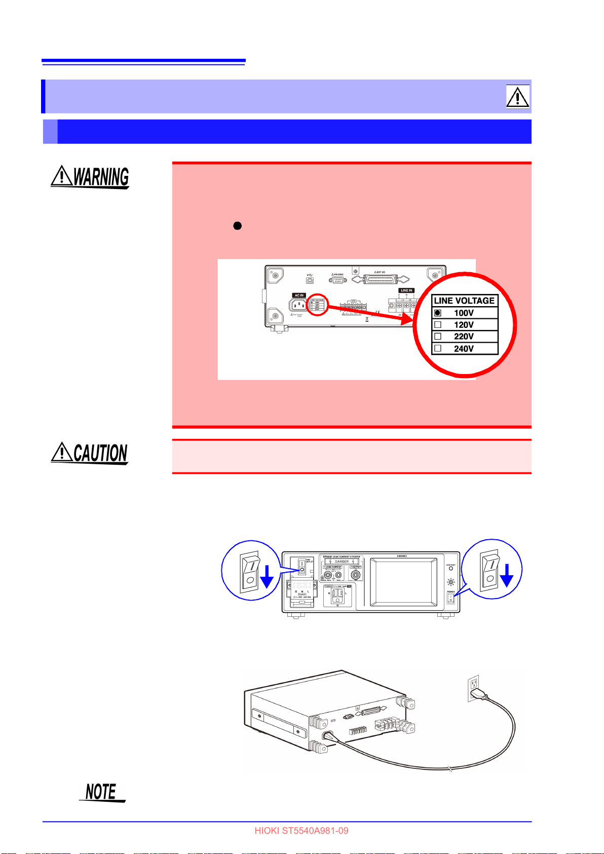
• Before turning on the instrument, confirm that the voltage of the power
source matches the voltage specification indicated on the instrument's
power connector ([AC IN]). (The voltage specification (100, 120, 220 or
240 V) ordered by the customer is marked with a black dot in the line
voltage column on the rear panel.)
Note that using the power supply with improper voltage may damage the
instrument and result in electrical hazards.
• To avoid electrical accidents and to maintain the safety specifications of
this instrument, connect the power cord provided only to a 3-contact
(two-conductor + ground) outlet.
Do not use excessive force on the touch panel, and do not use sharp objects that
could damage the touch screen.
6
HIOKI ST5540A981-09
Usage Notes
Fuse
Connection
• Replace the fuse only with one of the specified characteristics and
voltage and current ratings. Using a non-specified fuse or shorting
the fuse holder may cause a life-threatening hazard.
Measurement terminal section : 250 V F50 mAL
• To avoid electric shock, turn off the power switch and disconnect
the power cord and test leads before replacing the fuse.
• Since a blown fuse cannot be repaired or replaced by the cus-
tomer, contact your dealer or nearest Hioki sales office.
Use the VA check function for power supply fuse and blown fuse
check function for measurement circuit fuse to check for blown
fuses.
Measurement
• Always turn both devices OFF when connecting and disconnecting an inter-
face connector and test lead. Otherwise, an electric shock accident may
occur.
• To avoid damaging the power cord, grasp the plug, not the cord, when
unplugging it from the power outlet.
• To avoid breaking the test lead or enclosure probe, do not bend or pull them.
• When the power is turned off, do not apply voltage or current to the measurement terminals. Doing so may damage the instrument.
• L (Line), N (Neutral) and G (Ground) are indicated on the terminal block of the
instrument, and the contacts of the power cord of the device to be measured
are denoted L, N and E (Earth). If the power cord does not include an earth
(E) line, connect only the L and N terminals.
For details regarding the terminal block, refer to "3.3 Connecting equipment
under test to the instrument" (p. 36).
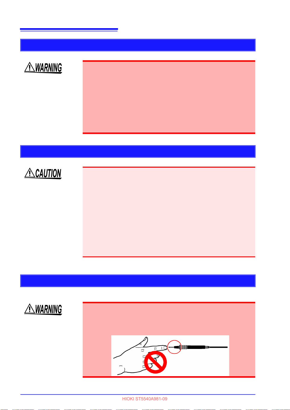
To avoid the risk of electric shock when test leads are connected to
the T1 - T3 terminals, do not touch the part of the test lead that is
beyond the finger barrier.
The terminals output high voltages in some measurement modes.
Do not touch any part of
the test lead beyond the
finger barrier

7
HIOKI ST5540A981-09
1.1 Instrument Overview
1
Overview Chapter 1
1.1 Instrument Overview
To ensure the safe use of electrical products, it is necessary to conduct electrical safety tests such as
insulation resistance, withstand voltage, ground resistance, and leakage current.
Complying with laws and standards regarding medical electrical equipment as well as non-medical electrical equipment, this instrument can be used to measure leakage current in all types of electrical products from computers to medical equipment. It consists of measurement networks that simulate the human
body and a high-frequency volt meter.
It is also capable of switching power supply polarities and making measurements under simulated singlefault conditions in equipment under test.
To simplify leakage current testing, all test operations can be selected and run from a touch panel on the
display screen.
Applicable lines of business and product applications
Manufacturers of medical electrical equipment Type approval testing, shipment inspection
Dealers of medical electrical equipment Maintenance, inspection
Service technicians for medical electrical equipment
(authorized service technicians)
Clinical engineers, hospitals Maintenance, inspection
Clinical engineering schools For educational purposes
Authorized electricians for operating rooms, ICUs,
and CCUs
Public organizations Type inspection
Manufacturers of general electrical equipment Type inspection, shipment inspection
Users of general electrical equipment Maintenance, inspection
General electrical equipment installers Maintenance, inspection
Service technicians for general electrical equipment Maintenance, inspection
Manufacturers of general electrical equipment parts Type inspection, shipment inspection
Manufacturers of power supply equipment Type inspection, shipment inspection
Manufacturers of electrical automobiles Type inspection, shipment inspection
Maintenance, inspection
Isolation transformer inspection
Chapter 1 Overview

8
HIOKI ST5540A981-09
1.2 Features
1.2 Features
Wide range of measurement networks in compliance with standards
and laws
To test electrical equipment for leakage current, it is necessary to use a measurement network that simulates the human body in compliance with applicable standards or laws.
The instrument includes the 8 measurement networks below.
1. Network A :For compliance with Electrical
Appliance and MaterialSafety Law
2. Network B1 :For JIS T0601-1:1999
IEC62353 (Some measurement modes require a separate power supply.)
3. Network B2 :IEC 60601-1:2005 3rd
Complies with JIS T 0601-1:2017
IEC62353 (Some measurement modes require a separate power supply.)
4. Network C :For IEC60990
5. Network D :For UL
6. Network E :For general-purpose 1
7. Network F :For general-purpose 2
8. Network G :For IEC 61010-1
The use of these networks enables instrument compliance with other standards.
* Unusable for the differential method defined in IEC 62353.
Leakage current measurement mode
Once a measurement network is selected, the instrument displays a leakage current measurement mode
corresponding to the applicable standard or law.
1. Earth leakage current
2. Touch current (Enclosure - Earth)
3. Touch current (Enclosure - Enclosure)
4. Touch current (Enclosure - Line)
5. Patient auxiliary current
6. Patient leakage current (Patient connection - Earth)
*
7. Patient leakage current (external voltage on a SIP/SOP
8. Patient leakage current (external voltage on a specific F-type applied part)
9. Patient leakage current
(external voltage on metal accessible part not protectively earthed)
10. Total patient leakage current (Patient connection - Earth)
11. Total patient leakage current (external voltage on a SIP/SOP
12. Total patient leakage current (external voltage on a specific F-type applied part)
13. Total patient leakage current
(external voltage on metal accessible part not protectively earthed)
14. Free current (Enclosure - Enclosure)
15. Enclosure - Earth leakage current
16. Enclosure - Enclosure leakage current
17. Enclosure - Line leakage current
18. Patient leakage current I
19. Patient leakage current II
20. Patient leakage current III
)
*
)
*
SIP(Signal Input Part)/SOP(Signal Output Part)
9
HIOKI ST5540A981-09
1.2 Features
Power on polarity switching function
This function makes it possible to continue testing without shutting down the equipment under test when
polarities are changed, which shortens the duration of the test.
(Be sure to use an isolation transformer when using power on polarity switching.)
Rated current 20 A
The instrument provides a rated current of 20 A and a rated voltage of 250 V.
Function for checking for blown fuses
The insutrument allows you to check for unintended blown fuses in networks.
Check for blown fuses before and after measurements to enable high-reliability measurements.
Ease of operation
All operations are performed using the touch panel. The display shows operable keys and the interactive
system guides you through measurement procedures.
1
Chapter 1 Overview
Interfaces
The RS-232C, EXT I/O and USB interfaces are provided as standard equipment to enable the easy
transfer of measurement data with a computer. The EXT I/O connector allows external control.
Printing (with optional printer)
Connect the optional 9442 Printer to print out measurement data and saved measurement data.
Monitor function
The instrument is equipped with a function to monitor the power supply voltage and current of equipment
under test.

10
HIOKI ST5540A981-09
1.3 What is Leakage Current?
1.3 What is Leakage Current?
High voltage is present in an electrical appliance that uses a commercial power supply as its main power
source. Touching such equipment may expose a person to an electrical shock when current passes
through the body to ground. This electrical shock is the result of "leakage current" or "touch current." Normally, electrical equipment is grounded to protect against electrical shocks. Current regularly flows
through the grounding wire, but should an abnormality (due to faulty design or fault) occur in equipment,
the resulting electrical shock may cause serious personal injury and sometimes lead to the death of the
*1
victim. For this reason, leakage current measurements including single-fault conditions
lated.
Leakage current measurements performed according to the applicable standard makes it possible to verify the safety of equipment.
*1
What is a single-fault condition?
This refers to when equipment has a fault in a safety protection measure, or a fault that may result in a
hazardous condition.
Leakage current testing includes the following three single-fault conditions.
are strictly regu-
1. Disconnected grounding wire (not applicable in current tests of leakage current)
2. One wire in the power cord is disconnected (neutral power supply wire)
*2
3. External equipment damage
(patient leakage current II and patient leakage current III)
*2
In JIS T0601-1:1999 classified as a single-fault condition.
Not a single-fault condition, the instrument is capable of switching polarity during measurements and
retaining a recording of the phase with the highest leakage current.

11
HIOKI ST5540A981-09
1.4 Leakage Current Measurement Complying with Standards
1.4 Leakage Current Measurement
Complying with Standards
Electrical safety standards and laws are enacted for electrical products according to fields of application.
Each standard and law specifies a circuit network for simulating the human body, and prescribes network
performance, as well as measuring locations, type (e.g., AC, DC) of current to be measured, allowable
values, and other characteristics.
Listed below are various standards that require leakage current measurement.
Standards requiring leakage current measurement
Electrical equipment
IEC 60065:2001 +A1:2005
IEC60335-1:2010
IEC 60950-1:2005 Safety of information technology equipment
IEC 60990:2016
UL2231-1, UL2231-2 Personnel Protection Systems for EV
Audio, video, and similar electronic apparatus - Safety
requirements
Safety of household and similar electrical appliances.
- Part 1: General requirements
Methods of measuring touch current and protective conductor current
1
Chapter 1 Overview
Electric measuring instruments
Safety requirements for electrical equipment used in mea-
IEC 61010-1:2010
Medical electrical equipment
JIS T 0601-1:1999
JIS T 0601-1:2017
IEC 60601-1:2005 3rd
Electric measuring instruments (maintenance)
IEC 62353:2014 2.0
surements, control and laboratories
Current measurement circuits for testing in damp conditions
Medical electrical equipment-Part1:General requirements
for basic safety and essential performace
Medical electrical equipment
Part 1: General requirements for safety
Medical electrical equipment
Recurrent test and test after repair of ME equipment
Method complying with IEC 61010-1

12
HIOKI ST5540A981-09
1.5 Types of Leakage Current
1.5 Types of Leakage Current
Leakage current can largely be classified as shown in the table below.
Types of
Leakage Current
Earth leakage
current
Touch current
Enclosure
leakage current
Patient leakage
current
Patient auxiliary
current
Total patient
leakage current
Protective
conductor current
Overview
This refers to electric current that flows through a protective earth conductor to
the ground.
Touch current is electric current that flows through a person who touches an
ungrounded enclosed section of equipment. It does not include current that
flows to the human body in contact with an applied part.
Patient leakage current flows through the body of someone connected to the
applied part.
Test items vary based on the type of applied part.
Electric current that flows between applied parts and through a patient during
normal operation of medical equipment that is not intended to have any physiological effect.
When multiple applied parts are attached to a patient, the total leakage current
must be measured.
The sum of patient leakage current of applied parts is total patient leakage cur-
rent.
Electric current that flows through a protective earth conductor (grounding
wire) during normal operating conditions
Refer-
ence
Page
P.13
P.14
P.15
P.15
P.19
P.20
13
HIOKI ST5540A981-09
1.6 Types of Leakage Current Measurement
1.6 Types of Leakage Current Measurement
Earth leakage current measurement
Class-II equipment does not require the measurement of Earth leakage current since it has no protective
earth conductor.
Earth leakage current is measured by inserting a resistance equivalent to the human body in the protec-
tive earth conductor. Using a clamp (Clamp On HiTester) for measuring current does not satisfy the standard.
1
Chapter 1 Overview

14
HIOKI ST5540A981-09
1.6 Types of Leakage Current Measurement
Touch current measurement
Class-I equipment does not require the measurement of enclosure leakage current since metal enclosures must be grounded for electrical protection.
disconnected (single fault), the enclosure is no longer grounded for protection and must be measured.
For Class-II equipment, all enclosures are ungrounded for electrical protection and must be tested.
Ungrounded equipment are often made of plastics and other insulated materials. Since leakage current
flows through the human body, the standard stipulates that a probe is applied to metal foil the size of a
hand pressed against the insulated material. Use the 9195 enclosure probe supplied with the instrument
for measurements involving this instrument.
There are two paths for touch current to flow: "enclosure
human body enclosure." Note that for "enclosure human body enclosure" to occur a person
must touch two electrically isolated (separate) enclosure sections not two sections on the same enclosure.
However, when the protective earth conductor becomes
human body earth" and "enclosure

15
HIOKI ST5540A981-09
1.6 Types of Leakage Current Measurement
Patient auxiliary current
Patient auxiliary current is current that flows through an "applied part human body applied part" path.
Regardless of the medical equipment class, type of applied parts, and signal input/output selection, all
medical equipment with multiple applied parts must undergo this measurement.
Make both AC and DC measurements for this type of leakage current.
1
Chapter 1 Overview
Patient leakage current measurement (Patient connection - Earth)
This is electric current that flows through an "applied part
Regardless of medical equipment class, type of applied parts and signal input/output section, all medical
equipment with patient connections must undergo this measurement.
Make both AC and DC measurements for this type of leakage current.
human body ground" path.

16
HIOKI ST5540A981-09
1.6 Types of Leakage Current Measurement
Patient leakage current measurement (external voltage on a SIP/SOP)
This is electric current that flows through an "applied part human body ground" path.
Measure medical instruments with a signal input/output section and applied parts other than F-type. Mea-
sure assuming that medical equipment with a broken signal input/output section is connected. Instead of
connecting damaged medical equipment to generate a single-fault condition, input a voltage that is 110%
of the rated voltage.
(Use the T3 terminal on the instrument)
IEC 60601-1:2005 3rd Edition stipulates that the connection of damaged medical equipment does not
constitute a single-fault condition, but handles it as a normal condition.
JIS T0601-1:1999 treats patient leakage current II as patient leakage current I plus a
single fault condition.
17
HIOKI ST5540A981-09
1.6 Types of Leakage Current Measurement
Patient leakage current measurement
(external voltage on a specific F-type applied part)
This is electric current that flows through an "applied part of malfunctioning medical equipment human
F-type applied part" path.
body
The measurement of this leakage current is required only for medical devices with an F-type applied part.
Instead of connecting damaged medical equipment to generate a single-fault condition, input a voltage
that is 110% of the rated voltage.
1
Chapter 1 Overview

18
HIOKI ST5540A981-09
1.6 Types of Leakage Current Measurement
Patient leakage current measurement
(external voltage on metal accessible part not protectively earthed)
Additions to IEC 60601-1:2005 3rd Edition
Patient leakage current is current that takes the following route: "metal accessible part not protectively
earthed
patient connection of applied parts that are not protectively earthed (B-type or BF-type) and with metal
accessible parts that are not protectively earthed.
Instead of connecting damaged medical equipment to generate a single-fault condition, input a voltage
that is 110% of the rated voltage to metal accessible parts not protectively earthed. (Use the T3 terminal
on the instrument)
This test is not required for CF-type applied parts.
applied part human body Earth." Use this standard to measure medical equipment with

19
HIOKI ST5540A981-09
1.6 Types of Leakage Current Measurement
Total patient leakage current measurement
Total patient leakage current is the total of all leakage current to or from patient connections of all the
same type of applied parts (B-Type, BF-Type and CF-Type applied parts) simultaneously connected.
When there are two or more patient connections that go to different functions and are not electrically connected together, the total patient leakage current for B-Type applied parts must be measured.
If required, measure all patient leakage current components (patient connection - earth, external voltage
on an SIP/SOP, external voltage on an F-type applied part, external voltage on a metal accessible part
that is not protectively earthed.)
(The figure shows patient - earth.)
1
Chapter 1 Overview

20
HIOKI ST5540A981-09
1.6 Types of Leakage Current Measurement
Protective conductor current measurement
A protective conductor current measurement measures the electric current that flows through a protective
earth conductor (grounding wire) during normal operating conditions.
Like Earth leakage current, class II equipment does not have a protective earth wire and therefore does
not require measurement of protective conductor current.
To measure the protective conductor current, place a resistor with a resistance so small as to be negligible in the protective earth wire circuit.
Measurement
HIOKI ST5540A981-09
Touch current
Enclosure - Line
1.6 Types of Leakage Current Measurement
List of Leakage-Current Measurement Items
Normal
condition
Single-
fault
condition
(Description of fault) (Other conditions)
Situation other than touch current
(Enclosure - Line) is applicable
21
1
Chapter 1 Overview
Touch current
•Enclosure - Earth
•Enclosure - Enclosure
Earth leakage current
1. One wire in the power
cord is disconnected.
2. protective earth conductor is disconnected
1. One wire in the power
cord is disconnected.
1. Functional grounding wire is disconnected
2. Grounding wire for patient connection and power
*
supply circuit for measurement are disconnected
3. A voltage that is 110% of the rated voltage is ap-
plied between an isolated signal input/output
section and earth (Not medical equipment)
1. Functional grounding wire is disconnected
(Class I only)
2. Grounding wire for patient connection and power
supply circuit for measurement are disconnected (Class I only)
General electrical equipment
Patient leakage cur-
rent (Patient connec-
tion - Earth)/
(Patient leakage
current I)
Patient leakage
current
(external voltage on a
SIP/SOP)/
(Patient leakage
current II)
Patient leakage cur-
rent (external voltage
Medical electrical equipment
on a specific F-type
applied part)/
(Patient leakage
current III)
Patient leakage cur-
rent (external voltage
on metal accessible
part not protectively
earthed)
Patient auxiliary
current
*
Measurement with a disconnected protective earth conductor is applicable only to Class-I equipment.
1. One wire in the power
cord is disconnected.
2. The protective earth
conductor is disconnected.
1. One wire in the power
cord is disconnected.
2. The protective earth
conductor is disconnected.
1. The protective earth
conductor is disconnected.
1. One wire in the power
cord is disconnected.
2. The protective earth
conductor is disconnected.
1 Functional grounding wire is disconnected
2. Grounding wire for patient connection and power
supply circuit for measurement are disconnected
1. Functional grounding wire is disconnected
2. Metal accessible part not protectively earthed
and grounding wire is disconnected
3. A voltage that is 110% of the rated voltage is applied between an isolated signal input/output
section and earth
1. A voltage that is 110% of the rated voltage is applied between an F-applied part and earth.
(Does not qualify as a single fault condition under IEC 60601-1: 2005 3rd Edition.)
2. Metal accessible part not protectively earthed
and grounding wire is disconnected
3. Functional grounding wire is disconnected
1. Applied to metal accessible part not protectively
earthed
2. Functional grounding wire is disconnected
Functional grounding wire is disconnected
22
HIOKI ST5540A981-09
1.6 Types of Leakage Current Measurement
ST5540/ST5541 List of functions
item ST5540 ST5541
Network A
Network B1
Network B2
Network
Testing leakage current mode
Major functions
Total patient leakage current
Enclosure - Earth leakage current
Enclosure - Enclosure leakage current
Enclosure - Line leakage current
Patient leakage current I
Patient leakage current II
Patient leakage current III
Power on polarity switching function
Function for checking for blown fuses
Frequency band switching
110% voltage output terminal (T3 terminal)
S10, S12, S13, E terminal
Network C
Network D
Network E
Network F
Network G
Earth leakage current
Touch current
Patient auxiliary current
Patient leakage current
Free current
Rated current 20 A
–
–
–
–
–
–
–
–
–
–
–

Instrument Labels
HIOKI ST5540A981-09
23
and Screens
Chapter 2
2
Chapter 2 Instrument Labels and Screens

24
HIOKI ST5540A981-09
2.1 Instrument Labels and Functions
2.1 Instrument Labels and Functions
Front Panel
1
11
10
9
8
2
3
1. Circuit breaker
Detects overcurrent in the power line for equipment
under test and activates a protective device.
(Rated current : 20 A)
: ON (for normal measuring operation)
: OFF (idle condition or when overcurrent
protection device has been triggered)
See (p. 31)
2. Terminal block cover
Covers the terminal block to prevent electric shock.
Turn the circuit breaker off ( ) before opening the
cover.
See (p. 37)
3. Terminal block
Outputs voltage based on the power supplied to
[LINE IN] (p. 25).
Also used to connect the power cord of equipment
under test.
See (p. 36)
4. Liquid crystal display unit (LCD)
Five-inch liquid crystal display unit with a touch
panel function.
Also provided with input key functions.
The backlight (p. 139) can be set to turn OFF automatically.
5. Power switch
Turns the main instrument ON and OFF.
See (p. 38)
7
6
5
4
6. Buzzer
Generates a beep sound when a key is pressed, and
activates a warning buzzer.
See (p. 138)
7. Contrast adjustment dial
Used to adjust screen contrast.
Turning the dial to the right darkens the display; turning to the left lightens the display.
Use this dial when the display requires adjustment.
8. 110% voltage output terminal (terminal T3)
Insulates the voltage supplied to [LINE IN] (p. 25)
using the built-in transformer and outputs a 1:1 voltage from terminal T3. Effective only when B1 or B2
network is selected. (only ST5540)
See (p. 75)
Input 110% of the rated voltage to [LINE IN] (p.
25) using the isolation transformer to use the T3
terminal. The T3 terminal will only output a 110% of
the rated voltage when the same voltage is input to
[LINE IN].
9. Warning lamp
Lights when high volltage is generated at the T1 - T3
terminals.
10. Measuring terminals (terminals T1)
11. Measuring terminals (terminals T2)
Used to measure leakage current other than Earth
leakage current. The T2 terminal is provided with a
protective fuse.
(fuse rating : 250 V, F50 mAL)
See (p. 75), (p. 285)

Rear Panel
HIOKI ST5540A981-09
25
2.1 Instrument Labels and Functions
6
5
1
2
1. Power inlet [AC IN]
Used for input of the power supply to operate the
instrument.
Used to connect the power cord provided.
2. Power source rating
Marked with a black dot (
specification section.
3. Inlet for power line of equipment under test
[LINE IN]
Used for input of the power supply for equipment
under test.
Used to connect the power cord provided.
(Maximum rating: 250 V/20 A)
Correct measurements are not made when no
voltage is input to [LINE IN].
See (p. 33)
4. EXT I/O connector
Input/output terminal for external control.
(The proper connector is required for connection.)
See (p. 247)
5. RS-232C connector
Used to connect an RS-232C cable or 9444 Connection Cable (for the 9442 Printer).
(The 9442 Printer, 9444 Connection Cable,
and other accessories are optional products.)
See (p. 141)
6. USB connector
Used to connect a USB cable.
(The USB terminal provides communication functions but no storage capacity.)
See (p. 141)
) in the power line voltage
7
8
4
9
10
7. S10 terminal*
Terminal for connecting function ground terminal
and power supply system for measurement. Connect to E (earth) for [LINE IN].
Enables connection to earth during leakage current
measurements. (only ST5540)
See (p. 35)
8. S12 terminal*
Terminal for connecting patient connection to
ground for power supply circuit for measurement.
Connect to E (earth) for [LINE IN].
Enables connection to earth during leakage current
measurements. (only ST5540)
See (p. 35)
9. S13 terminal*
Terminal providing ground connection for metal
accessible part not protectively earthed. Connect to
E (earth) for [LINE IN]. Enables ground connection
during leakage current measurements. (only
ST5540)
See (p. 35)
10. E terminal
Connected to E (earth) of [LINE IN].
This is a permanent connection that cannot be
changed.
*
Setting enabled only when B1 or B2 network
is selected.
2
Chapter 2 Instrument Labels and Screens
3

26
HIOKI ST5540A981-09
2.1 Instrument Labels and Functions
Side Panel
1
2
1. Handle
Used to carry the instrument.
2. Stand
Used to tilt the instrument.
Take the following precautions to prevent electric shock accidents and damage
to the instrument.
• Use M3 screws to attach rack mount brackets after removing the feet.
• When the rack mount brackets are removed to restore the instrument to its
original condition, be sure to use the original screws.
• The screws used must not penetrate more than 5 mm below the metal panels.
• Do not apply heavy downward pressure with the stand extended. The stand
could be damaged.

2.2 Screen configuration outline
HIOKI ST5540A981-09
2.2 Screen configuration outline
The following example shows screens that appear after selecting network A. (Screens for networks C to
G look the same as the screen for network A only the network keys differ. Due to the larger number of
measurement mode keys, selecting network B1 opens three initial screens and selecting B2 opens four
initial screens.)
27
2
Chapter 2 Instrument Labels and Screens
Network select screen
Select network to use. (p. 48)
Network select screen 1
Network
key
measurement
mode keys
Network select
screen 2
Return to initial screen 1.
Initial screen 1
Setting screen of
equipment under test
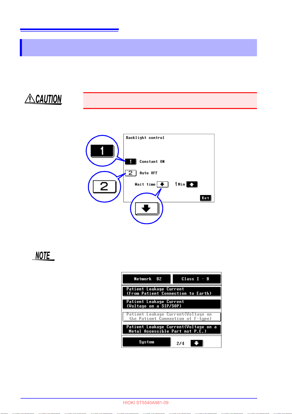
Set up equipment under test.(p. 49)
Return to initial screen 1.
Initial screen 2
Go between pages.
System screen
Press to set up the system. (p. 115)
Return to initial
screen 1.
Go between pages.
Measurement screen
Set measurement conditions for the
selected measurement mode. (p. 51)
Return to initial screen 1.

28
HIOKI ST5540A981-09
2.2 Screen configuration outline
Shared measurement screen displays
The following describes shared measurement screen displays.
(Screen example : Earth leakage current measurement screen)
Result of comparison between maximum value and
allowable value.
PASS
FAIL : Maximum value is greater than the Upper
LOW : Maximum value is equal to or less than
Range Up
Measurements exceed the guaranteed accuracy range.
(PASS or FAIL is not determined)
Range Down:
Measurements drop below the guaranteed accuracy
range. (PASS or FAIL is not determined)
Current measurement
mode
Maximum measurement
value in same
measurement item
Measurement conditions
at maximum value
acquisition
: Maximum value is equal to or less than
the Upper limit value.
limit value.
the Lower limit value.
:
Result of comparison between current measurement
value and allowable value.
PASS
FAIL
LOW : Current measurement value is equal to or
Range Up
Measurements exceed the guaranteed accuracy range.
(PASS or FAIL is not determined)
Range Down:
Measurements drop below the guaranteed accuracy range.
(PASS or FAIL is not determined)
: Current measurement value is equal to or
less than the Upper limit value.
: Current measurement value is greater than
the Upper limit value.
less than the Lower limit value.
:
Current measurement value
Current measurement value is
minus
Current measurement conditions
Currently set
allowable value
Selected network
Grounding class
Equipment name
Control number
Date
Measurement screen (manual measurement)

Key description
HIOKI ST5540A981-09
Shared keys
Clears the maximum value.
Unless this key is pressed, the maximum value is not cleared even if measurement conditions are changed in the same measurement mode.
Changing the measurement mode clears the maximum value.
Displays the allowable value setting screen.
See "4.6 Setting the Allowable Value" (p. 61)
The measurement condition setup screen appears.
See "4.8 Changing the Measurement Method (Auto/Manual)" (p. 67)
Displays the filter setting screen. (When a filter selection is available)
Used to turn the filter ON and OFF, or change the setting of the filter.
See "4.5 Setting the Filter" (p. 59)
Displays the screen for setting the target current.
(When an target current selection is available)
See "4.7 Selecting the Type of Target Current" (p. 64)
Displays the screen for setting the measurement range.
Switches the range between Auto and Hold.
See "4.4 Setting the Measurement Range (Auto/Hold)" (p. 54)
29
2.2 Screen configuration outline
2
Chapter 2 Instrument Labels and Screens
Displays the screen for selecting data to be saved.
See "6.4 Saving Measurement Data (As required)" (p. 102)
Starts transmitting data to the 9442 Printer (option).
This key is displayed only when the interface setting is set to "Printer".
See "6.6 Printing Measurement Data (as required)" (p. 108)
Exits the currently selected measurement mode, and returns to the system screen.
Specific keys (not displayed for some measurement method)
Applies a high voltage to a test lead connected to the T3 terminal.
See "6.3 Measurement examples" (p. 83)
Starts automatic measurements.
See "6.2 Making automatic measurements" (p. 82)
During automatic measurement : Stops automatic measurements.
During application : Stops output of high voltage.
During printing : Terminates printing.
See "6.2 Making automatic measurements" (p. 82)
See "6.3 Measurement examples" (p. 83)
See "Printing" (p. 111)
Displayed only when the frequency range is set from 0.1 Hz.
Press this key to adjust the measurement value.
(Measurement values are automatically adjusted when set from 15 Hz.)
Displayed when patient leakage current (patient - earth) and internally powered equipment
are selected.
See "Measuring the internally powered equipment 1" (p. 91)
See "Measuring the internally powered equipment 2" (p. 92)
30
HIOKI ST5540A981-09
2.3 About the Touch Panel
2.3 About the Touch Panel
The HiTESTER uses a touch panel for setting and changing all of the measurement conditions.
Gently touch the black keys on the screen to make settings and selections. A key turns white and has a
concave look when selected. In this manual, lightly touching a soft key area on the screen is termed
"pressing" a key.
Do not use excessive force on the touch panel, and do not use sharp objects that
could damage the touch screen.
Keys on screen
Selectable keys
(Black)
Selected keys
(indicated in white
and pushed in)
Non-selectable keys
(indicated in white and
protruding)
Keys whose key captions appear as dotted lines are keys for measurement
modes not required for the selected grounding class.

Setting
HIOKI ST5540A981-09
31
3.1 Power switch, breaker ON/OFF
Preparations
Chapter 3
3.1 Power switch, breaker ON/OFF
Circuit
ON
OFF
3
Chapter 3 Setting Preparations
Power switch
ON
OFF
32
HIOKI ST5540A981-09
3.2 Connecting the Power Cord
3.2 Connecting the Power Cord
Connecting the instrument power cord
• Before turning on the instrument, confirm that the voltage of the
power source matches the voltage specification indicated on the
instrument's power connector ([AC IN]). (The voltage specification
(100, 120, 220 or 240 V) ordered by the customer is marked with a
black dot in the line voltage column on the rear panel.)
Note that using the power supply with improper voltage may damage the instrument a
nd resu
lt in electrical hazards.
•
To avoid electrical accidents and to maintain the safety specifications of this instrument, connect the power cord provided only to
a 3-contact (two-conductor + ground) outlet.
To avoid damaging the power cord, grasp the plug, not the cord, when unplugging it from the power outlet.
Preparation items : Power cord for main instrument
1. Confirm that the main power switch on the front panel of the main instrument and the circuit
breaker are turned off.
2. Connect the power cord to the [AC IN] power inlet on the rear panel of the main instrument, and
insert the power cord plug into a power outlet that supplies the voltage specified for the instrument.
[AC IN]
The ground (G) for the power inlet [AC IN] is a protective earth conductor and is
connected to the enclosure of the instrument.

33
HIOKI ST5540A981-09
3.2 Connecting the Power Cord
Connecting the power cord of the equipment under test
Preparation items : Power cord for equipment under test
Isolation transformer (separately purchased)
1. Confirm that the main power switch on the front panel of the main instrument and the circuit breaker
are turned off.
2. Connect the supplied power cord of the equipment under test to the [LINE IN] line power terminal
block for equipment under test on the rear panel of the instrument.
3
Chapter 3 Setting Preparations
3. Connect the plug of the power cord to the isolation transformer.
4. Connect the isolation transformer plug to a power supply with the voltage specified by the equip-
ment under test.
2
E
LNE
Isolation
transformer
Use the screws
to secure
the connection
N
L
4
Secondary side of the
Isolation transformer
3
[LINE IN]
[AC IN]
• When the power on polarity switching function is used, be sure not to
connect the neutral wire on the secondary side of the isolation transformer to ground. If it is connected to ground, a ground fault will occur.
• Use a voltmeter or voltage detector to make sure that terminal E [LINE IN]
is at ground potential (approx. 0 V). Failure to make this confirmation
could lead to electric shock or damage the instrument or the equipment
under test.
• When connecting the power cord of the equipment under test to the
[LINE IN] terminal, use a cord suitable for the capacity of the equipment
under test. Using a power cord with another rating may result in fire.

34
HIOKI ST5540A981-09
3.2 Connecting the Power Cord
• Use of network B1 or B2 requires the connection of an isolation transformer
capable of outputting a voltage equivalent to 110% of the rated power supply
voltage of the equipment under test.
• When network C is selected, an isolation transformer is required.
However, when the power on polarity switching function is not used, connect
the neutral wire on the secondary side to ground. When the function is used,
not to connect the neutral wire to ground.
• The [LINE IN] and [AC IN] power supplies are isolated from each other.
• Use the cable supplied with the ST5540 and ST5541 instruments to connect
the equipment under test [LINE IN]. Do not connect any other electrical appliance to this inlet.
• The [LINE IN] terminal cannot be used to connect a single-phase three-wire
or center-grounded power supply (for example, a stabilized power supply).
• Nor will the input of 110% of a rated 250 V power supply voltage be a problem.
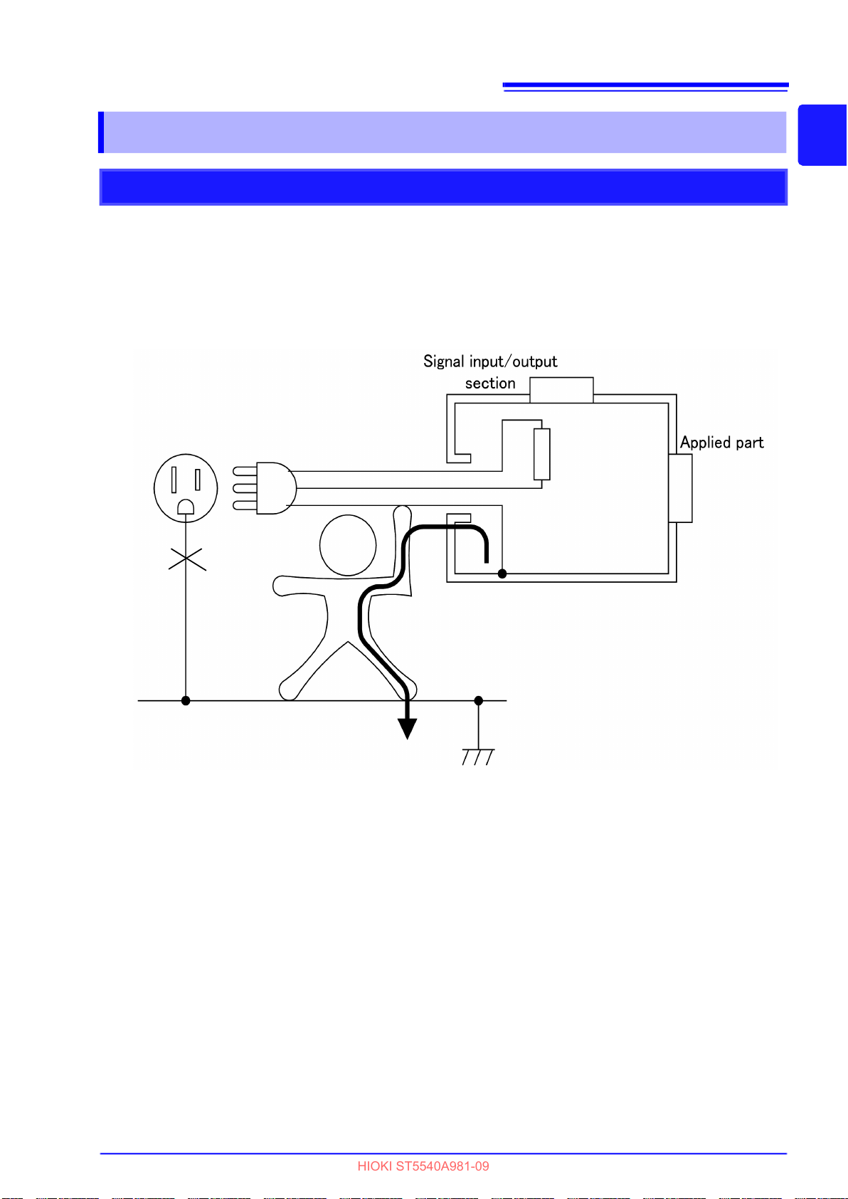
Description of isolation transformer
The standard requires that an isolation transformer is used for performing leakage current measurements.
Should the equipment under test break down during measurements, unforeseen current could be generated resulting in tripping the earth leakage breaker. Such an event could shut down other electrical equipment used in the same facility, which could cause a serious accident. Since an isolation transformer
isolates equipment under test from the earth leakage breaker, equipment breakdown will not have an
impact on the earth leakage breaker or on any other equipment.
Voltage fluctuations of ±10% from the rated supply voltage are taken into
account. Nor will the input of 110% of a rated 250 V power supply voltage be a
problem.

3.2 Connecting the Power Cord
HIOKI ST5540A981-09
Making connections to terminals S10, S12 and S13
1. Make sure that the connection to [LINE IN] is correct.
35
E
E
If the wrong connection has been made to [LINE IN], the E terminal may
output the power supply voltage. Since there is then a risk of electric
shock, make sure that the [LINE IN] connection is correct before making
connections to the S10, S12 and S13 terminals.
LN
N
L
2. Make connections to S10, S12 and S13 to prepare for a leakage current test.
S10 terminal
S12 terminal
S13 terminal For testing connection of metal accessible part not protectively earthed to ground
For testing connection of function ground terminal to ground of power supply system for measurement
For testing connection of patient connections to ground of power supply system
for measurement
Use the screws
to secure
the connection
3
Chapter 3 Setting Preparations
Example: Connecting S10 terminal to functional earth terminal
S10 terminal and
functional earth terminal
• S10, S12 and S13 are internally connected to the [LINE IN] E terminal (E terminal is permanently connected to the [LINE IN] E terminal) and correct measurements are not possible unless a power supply is connected to [LINE IN].
• When you do not know whether the S10, S12 or S13 terminal should be used,
refer to the documentation supplied with the equipment under test.

36
HIOKI ST5540A981-09
3.3 Connecting equipment under test to the instrument
3.3 Connecting equipment under test to
the instrument
The actual connection procedure will vary with the power supply of the equipment under test. A cord to
connect the instrument and the equipment under test is not supplied. Use a power cord that suits the
power supply of the equipment under test.
• To avoid electrical accidents, confirm that all connections are secure.
The increased resistance of loose connections can lead to overheating
and fire.
• To avoid electric shock or damage to the equipment, always observe the
following precautions when connecting to external terminals.
Always turn off the power to the instrument and to any devices to be connected before making connections.
Be careful to avoid exceeding the ratings of external terminals and connectors.
During operation, a wire becoming dislocated and contacting another
conductive object can be serious hazard. Make sure that connections are
secure and use screws to secure the external connectors.
he permissible current for the terminal block is 20 A. Current exceeding
• T
this limit will trip the breaker and shut down the power supply of the
equipment under test.
Connect the terminal
When connecting the HiTESTER to equipment under test with a power cord, use the terminal
block.
• L (Line), N (Neutral) and G (Ground) are indicated on the terminal block of the
instrument, and the contacts of the power cord of the device to be measured
are denoted L, N and G. Connect the wires as shown below. Other wiring configurations may cause electric shock or damage.
• If the power cord does not include an Ground (G) line, connect only the L and
N terminals.
Power cord (cable case)
HiTESTER
Terminal block
LNG
• When reinstalling the terminal block cover, hang the connected wires straight
down to prevent the wires from being pinched by the cover. Otherwise, the
wires may be disconnected when pinched by the cover.
• To avoid the risk of electric shock and short-circuiting, use the supplied power
cord to connect the measurement line and voltage input terminal.
E
N
L

3.3 Connecting equipment under test to the instrument
HIOKI ST5540A981-09
Connecting wires to the terminal block
37
Turn off the instrument and set the breaker to Off.
1
See "Turning Power Off" (p. 40)
See "3.1 Power switch, breaker ON/OFF" (p. 31)
2
Slide upwards
Turn on the HiTESTER.
6
See "3.4 Turning Power On and OFF" (p. 38)
3
Raise the cover.
(The cover will stay in
place when raised to a
certain height)
Fit the right and left projecting portions of the terminal block cover
into the panel slit. Slide the cover
downwards until it clicks into place
4
L
N
G
Check that the G, N and L terminals
are correctly connected and make
sure the wires are properly secured
Turn on the instrument.
G : For grounding wire connection
(Class-I equipment only)
N : For neutral wire connection
L : For live wire connection
5
Clicking
sound
3
Chapter 3 Setting Preparations
Using a wiring adapter
Obtain and use a wiring adapter as shown below.
Multi-connection adapter, etc.
• Turn off the circuit breaker connecting a wiring adapter or equipment.
• The terminal block continuously output the voltage based on the power sup-
plied to [LINE IN].
Leakage current will increase with the use of multi-connection adapters, etc.

38
HIOKI ST5540A981-09
3.4 Turning Power On and OFF
3.4 Turning Power On and OFF
Turning Power On
• Before turning on the instrument, confirm that the voltage of the power
source matches the voltage specification indicated on the instrument's
power connector ([AC IN]). (The voltage specification (100, 120, 220 or
240 V) ordered by the customer is marked with a black dot in the line
voltage column on the rear panel.)
Note that using the power supply with improper voltage may damage the
instrument and result in electrical hazards.
• T
o avoid electrical accidents and to maintain the safety specifications of
this instrument, connect the power cord provided only to a 3-contact
(two-conductor + ground) outlet.
• Before turning on the power switch, confirm that the circuit breaker is turned
off. Even if the instrument was turned off in fault mode (i.e., disconnection of
one wire in the power line) at last use, the instrument will be initialized to normal condition when the power switch is turned on. Therefore, the terminal
block outputs voltage.
• The instrument can operate continuously for 30 minutes at maximum load.
Measurements that continue for longer than 30 minutes may raise internal
temperature and thereby trip the circuit breaker.

39
HIOKI ST5540A981-09
3.4 Turning Power On and OFF
1
1. Confirm that the circuit breaker is turned off.
(If the instrument is turned on when the circuit breaker is
On, the circuit breaker may be triggered.)
2. Turn on the power switch (ON: ) on the front panel.
3. The LCD shows the opening message.Then the wiring
check screen appears.
4. Use the contrast adjustment dial to set the LCD for easy
viewing.
5. Turn the circuit breaker On and press to check
wires connected to LINE IN.( appears only when
4
Wiring check screen
Check again.
5
2
3
Chapter 3 Setting Preparations
6
wiring is incorrect. Press for advice.)
6. Press to open the fuse check screen.
See "7.5 Checking Fuses (During Earth leakage current and
protective conductor current measurements: Fuse on the
relay board )" (p. 124)
7. Pressing in the fuse check screen opens the
relay check screen.
See "Relay Check" (p. 41)
8. Pressing in the relay check screen,The network
select screen appears by default.
If the instrument was turned off with the LCD showing
the measurement screen at last use, that measurement
screen appears.
If the instrument was turned off with the LCD showing a
screen other than the measurement screen, the initial
screen appears.
9. After turning the power on, let the instrument warm up
for about 20 minutes before starting measurement oper-
When "Check at each power ON operation" is enabled on the connection/VA
check screen, the connection/VA check screen appears after the power switch is
turned on.
See ."Inspecting line power supply for the equipment under test" (p. 42)
(If the power on polarity switching function was on when the instrument was last
turned off, a message to check isolation transformer connection and precautions
appear before the wiring check screen.)
When the grounding class of the equipment under test is set to internally pow-
ered equipment, is displayed, and after the initial measurement, the voltage value will not be renewed as long as "Renew" is not pressed.
7
Fuse check screen
8
Relay check screen
40
HIOKI ST5540A981-09
3.4 Turning Power On and OFF
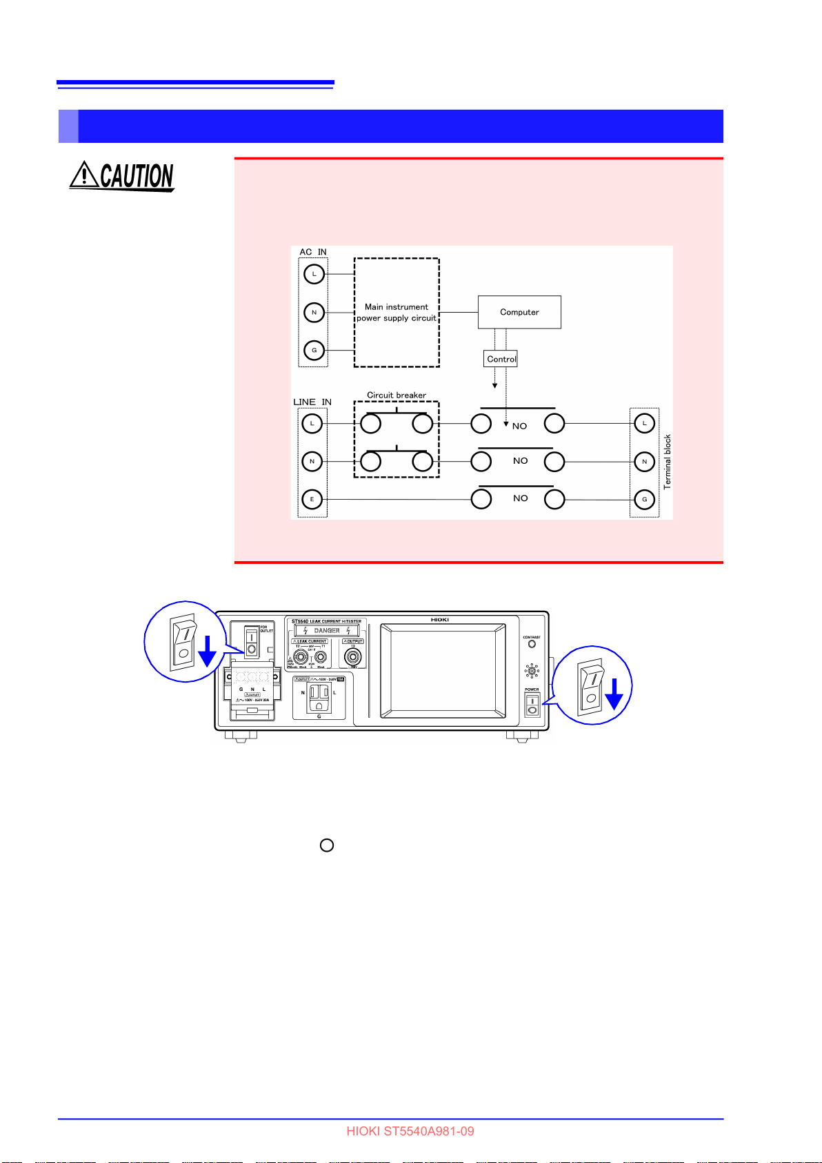
Turning Power Off
Always turn off the power switch of equipment under test before turning off
power of the instrument to avoid damaging the equipment under test. The instrument uses an internal relay for switching the power line to equipment under test
and turning off the power switch of the instrument opens all lines and turns off
the equipment under test.
NO:Normally open
Condition of power line for equipment under test with the main
instrument power switch turned OFF (schematic diagram)
2
1. Turn off the power switch of equipment under test connected to the terminal block.
2. Turn off the circuit breaker.
3. Turn off the power switch (OFF: ) on the front panel.
When the power switch is turned off, the measurement conditions are saved. In case of power
supply failure (e.g., power outage), the instrument restores the conditions held immediately
before power failure occurred.
3
41
HIOKI ST5540A981-09
3.5 Pre-Test Inspection
3.5 Pre-Test Inspection
Do not leave any equipment under test connected to the instrument
during the relay check and fuse check (when using any mode other than
earth leakage current mode or protective conductor current mode). The
equipment under test can be subjected to unexpected voltage due to the
internal circuit architecture, damaging the equipment under test.
Before using the instrument the first time, verify that it operates normally to ensure that no damage occurred
during storage or shipping. If you find any damage, contact your dealer or Hioki representative.
Pre-connection inspection
Does any cable insulation appear damaged,
or is bare metal exposed?
Is damage to the instrument evident?
Does the power supply use single-side-
grounded wiring?
Do not use if damage is present, as you could receive an electric shock. Contact your dealer or Hioki representative if you
find any damage.
When using a center-grounded wiring type power supply (for
example, a stabilized power supply), you may not be able to
perform all checks accurately.
3
Chapter 3 Setting Preparations
Power-on confirmation
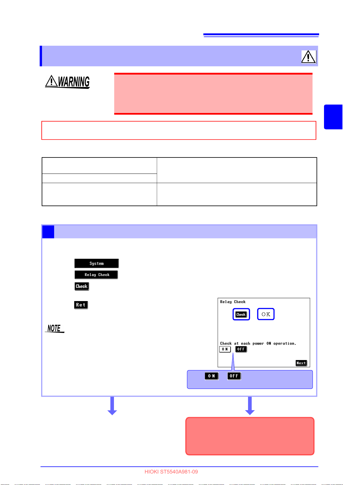
Relay Check
1
Enables the user to check whether the measurement network and internal circuit relays work normally.
(1) Press on the initial screen to display the system screen.
(2) Press to open the relay check screen.
(3) Press to start a relay check.
(4) An "OK" appears when the check ends without error.
(5) Press to return to the system screen.
3
Supply power via [LINE IN] and turn the circuit breaker
On as a relay check will otherwise not operate normally.
Always confirm this before performing a relay check.
Do not connect a device under test during a relay check.
Press or to select whether the check
is to be conducted each time power is turned.
Relay check screen
4
An "OK" is displayed
See next page.
A "NG" is displayed
A "NG" indication indicates that the measurement network or an internal relay does not work
normally. As the instrument is not in normal
working order, contact your dealer or nearest
Hioki sales office.

42
HIOKI ST5540A981-09
3.5 Pre-Test Inspection
Fuse inspection (when using modes other than Earth leakage current
2
and protective conductor current modes: T2-terminal fuse)
For details about the fuse check for the relay board, see "Checking Fuses (During Earth leakage current and
protective conductor current measurements:"7.5 Checking Fuses (During Earth leakage current and protective conductor current measurements: Fuse on the relay board )" (p.
124)
The current detection circuit in the instrument contains a fuse.
Should the fuse blow due to incorrect wiring or an over-current
condition, the instrument may no longer be able to detect current.
Before use, make sure that the fuse is not blown.
Required items
• A device for measuring impedance
(for example, a tester)
(1) Select network E in the Network Select screen and select
Enclosure - Enclosure leakage current.
(2) Use a tester to measure the impedance between
the T1 and T2 terminals on the front panel.
(Or place the tip of test leads connected to the T1 and T2 terminals on the tester to measure.)
(3) Check that an impedance value of 1015
10 is obtained.
Network E : Enclosure-Enclosure
leakage current measurement screen
When the tester is connected to the T1 and T2 terminals, the instrument measures the
leakage current going through the tester.
The impedance is not
1015 10 .
Remove the fuse from the T2 terminal, and directly measure the
fuse resistance.
The impedance is about 15 .
(The fuse is not blown.)
Inspecting line power supply for the equipment under test
3
Check the line power supply of the equipment under test.
(1) Press in the initial screen.
(2) Turn on the circuit breaker of the instrument. (p. 31)
(3) Press to display the connection/VA
check screen.
(4) The check is made automatically.
(5) Press to return to the system screen.
The impedance is
not about 15 .
The impedance is an
overflow
The fuse at the T2 terminal on the front of the
instrument may be blown, or a non-specified
fuse may be inserted. Replace the fuse.
See "11.3 Replacing Fuses" (p. 285)
Supply power via LINE IN and turn the circuit breaker On as a
connection / VA check will not otherwise operate normally.
Always confirm this before performing a connection / VA check.
(When network B2 is selected(p. 43))
Inspection complete
Press or to select
whether the check is to be conducted
each time power is turned.
An "NG" appears
Press to display the screen that shows advice concerning the present condition. According to the displayed
advice, check the current consumption, power cord connection, and other aspects of the equipment under test.
See "About the NG Indication" (p. 44)
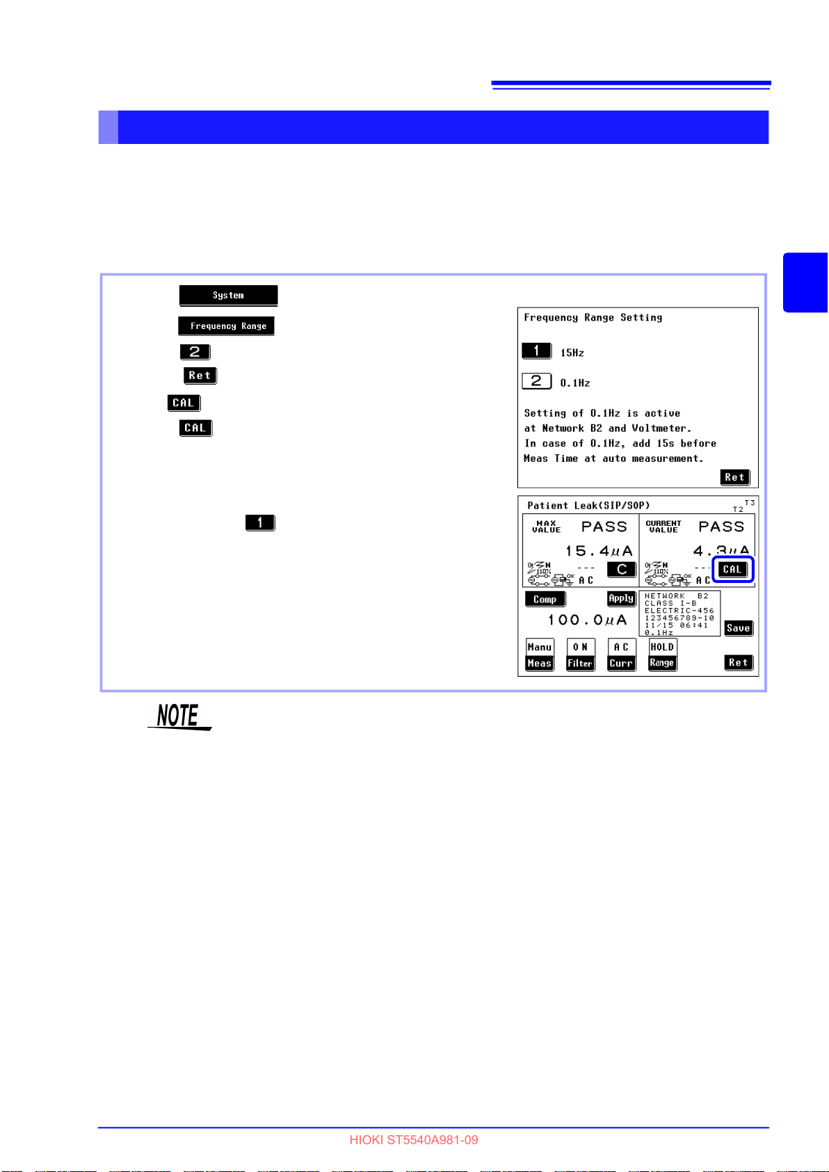
3.5 Pre-Test Inspection
HIOKI ST5540A981-09
Checking measurement frequency
When network B2 is selected
The frequency range setting of the instrument is 0.1 - 1 MHz allowing the user to select 0.1 Hz - 1 MHz or
15 Hz - 1 MHz. An 0.1 Hz - 1 MHz setting will slow down the response of internal circuits and increase
measurement time. Therefore perform the following tests to check the frequency range setting when
using a B2 network. (Default setting: 15 Hz - 1 MHz)
43
(1) Press in the initial screen.
(2) Press .
(3) Press and set a frequency range setting of 0.1 Hz.
(Press to confirm and return to the system screen.)
(4) The appears when 0.1 Hz frequency range is set.
Press and adjust the value
(5) Measure the leakage current of the equipment under test
and record the measured value.
(Perform this measurement for 1 or 2 minutes.)
(6) When recording ends, perform operations in step (1) and (2)
again and press and set a frequency range setting of
15 Hz.
(7) Measure the leakage current of the equipment under test
and compare this value with the value obtained in the 0.1 Hz
- 1 MHz setting.
Unless the two values differ substantially, the customer's
equipment under test does not produce any leakage current
and the 15 Hz - 1 MHz setting is enough for any subsequent
measurement.
3
Chapter 3 Setting Preparations
Check the frequency range setting at regular intervals.
• Use the 0.1 Hz setting only for measurements in the B2 network.
• Selecting a network other than the B2 network in an 0.1 Hz setting will invali-
date the 0.1 Hz setting. (The display does not change.)
• The auto range is not available when a 0.1 Hz frequency range setting is
made. Selecting auto range automatically sets the hold range. (during ACpeak
measurements: 1.000 mA range; during AC/DC/AC+DC measurements: 500.0
A range)
• Setting the frequency range to 0.1 Hz in voltmeter mode engages the hold
range (500.0 mV range).
• Setting the frequency range to 0.1 Hz when ACPeak is selected in leakage
current meter mode selects ACDC.
• The CAL key appears when 0.1 Hz frequency range is set.
See "Specific keys (not displayed for some measurement method)" (p. 29)

44
HIOKI ST5540A981-09
3.5 Pre-Test Inspection
Connection/VA check screen
Indicates the voltage of power supplied to [LINE IN].
Indicates the current consumption of the equipment
under test.
Indicates the power consumption.
Measures voltage between the terminals of [LINE IN]
to check the polarity.
Indicates the voltages between phase L and terminal
G and between phase N and terminal G on the terminal block.
Press or to select whether the check is to
be conducted each time power is turned.
Check again.
When the grounding class of the equipment under test is set to internally powered equipment, is displayed, and after the initial measurement, the volt-
age value will not be renewed as long as "Renew" is not pressed.
About the NG Indication
1. If the result of a check is judged not normal, an "NG" indication appears to the right of the corre-
sponding item, along with a key for the display of details.
(In the screen example shown on the below, the voltage is not normal (NG).)
2. Press to display the screen that shows advice concerning the present condition. According
to the displayed advice, check the current consumption, power cord connection, and other
aspects of the equipment under test.
The polarity check’s key may be displayed for uninterrupted polarity
switching wiring but does not indicate a problem with the wiring. When the uninterrupted polarity switching function has been enabled, an uninterrupted performance check (uninterrupted polarity switching wiring check) is performed before
measurement to check the wiring.
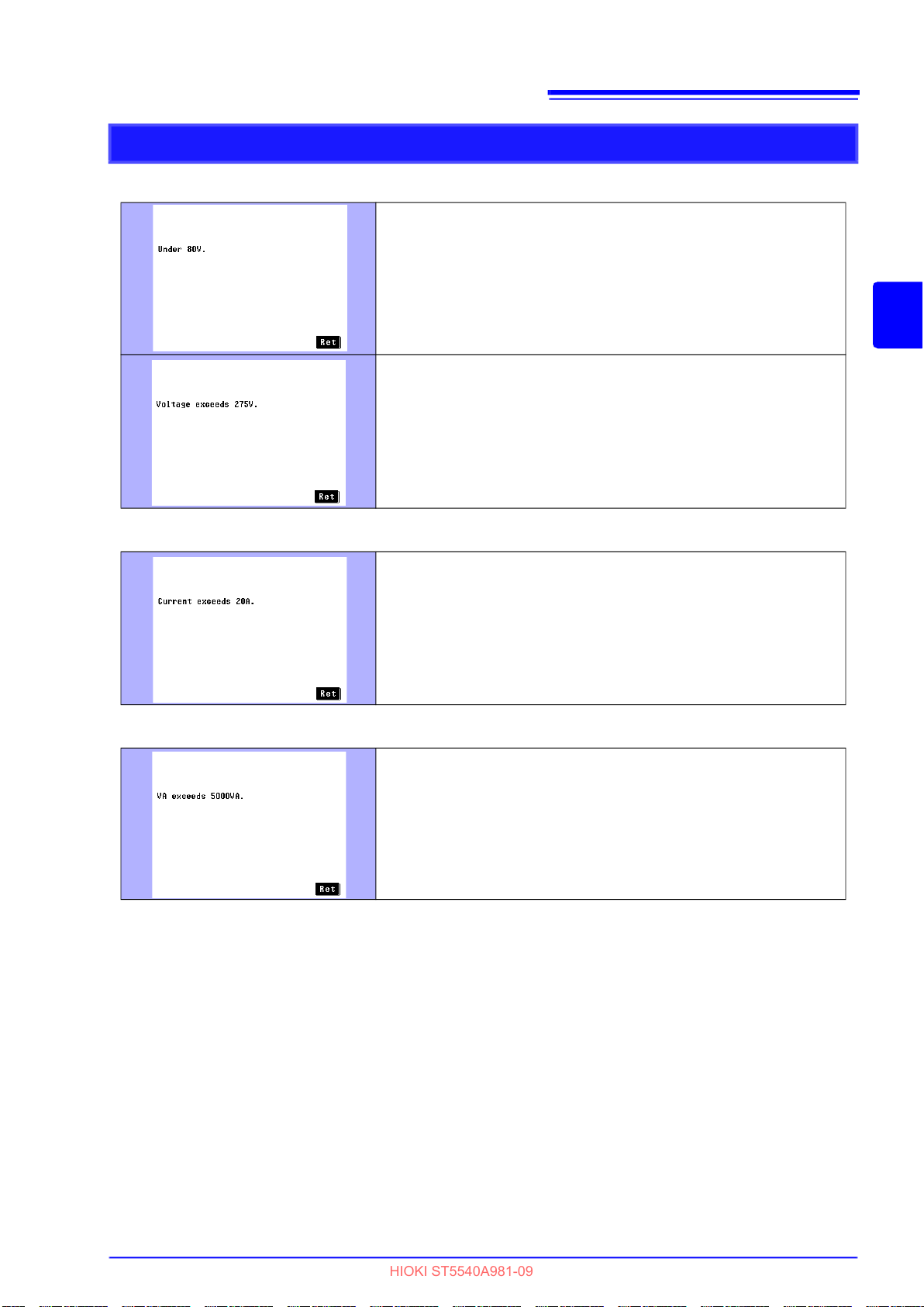
Check examples
HIOKI ST5540A981-09
(1) If the voltage check results in NG
• Check the voltage of the power supply.
• Check whether the circuit breaker is ON.
• The internal fuse (power) may be blown.
Check connections.
The maximum allowed power supply voltage is 275 V.
45
3.5 Pre-Test Inspection
3
Chapter 3 Setting Preparations
(2) If the current check results in NG
Reduce the current to 20 A or less.
(3) If the VA check results in NG
The VA (voltage x current) must be 5,000 VA or lower.

46
HIOKI ST5540A981-09
3.5 Pre-Test Inspection
(4) Polarity check results
The wiring may not be configured for uninterrupted polarity
switching. Check the wiring.
• The grounding wire may be disconnected.
• The power supply may be a floating power supply.
• The power supply may be a single-phase, 3-wire power
source.
The polarities of the power supply are reversed.
Reverse the L and N wire connections on [LINE IN].
See "Connecting the power cord of the equipment under test" (p. 33)

47
HIOKI ST5540A981-09
Settings Chapter 4
The setup procedure differs with the measurement method (Manual/Automatic).
Manual
measurement :
Perform the settings described from "4.1 Selecting a Network" (p. 48) to "4.8 Changing the Measurement
Method (Auto/Manual)" (p. 67).
3
Automatic
measurement :
Perform the settings described from "4.1 Selecting a Network" (p. 48) to "Setting the measuring time" (p. 73).
4
Chapter 4 Settings
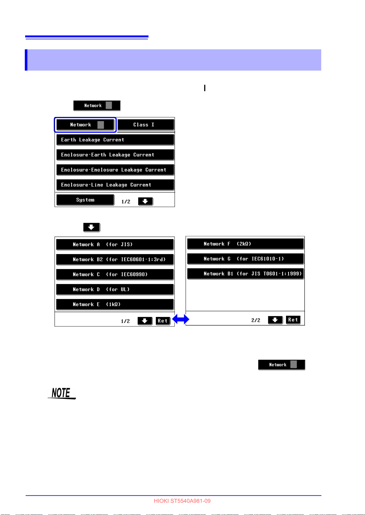
48
HIOKI ST5540A981-09
4.1 Selecting a Network
4.1 Selecting a Network
1. After the power switch of the HiTESTER is set to ON ( ), the initial screen appears.
2. Press and then display the network select screen.
Initial screen
Press the to switch the network selection screen.
Network select screen 1
Network select screen 2
3. After the desired network is selected, the initial screen appears.
To change the network, return to the network select screen by pressing the key.
• The instrument normally functions as an ammeter, but will operate as a volt-
meter when "voltmeter" is selected in the mode setting screen.
When the network configuration not supported by networks A to G is required,
your own network can be connected for testing by using the instrument as a
voltmeter.
See "7.1 Setting the Mode (Using the instrument as a voltmeter / measuring protective
conductor current)" (p. 117)
• Once a network is selected, the initial screen appears the next time power is
turned on. If turning the power switch off with the measurement screen displayed, the measurement screen is redisplayed the next time power is on.

4.2 Selecting the Grounding Class of Equipment Under Test
HIOKI ST5540A981-09
4.2 Selecting the Grounding Class of
Equipment Under Test
2
49
3
Initial screen
1
3
4
Setting screen of equipment under test
(when selecting network A, C, D, E, F or G)
2
3
4
Setting screen of equipment under test
(when selecting network B1 or B2)
4
Chapter 4 Settings
1. On the initial screen, press the key to display the setting screen of the equip-
ment under test.
2. Set the grounding class of the equipment under test.
Inspection of Class-I equipment
Inspection of Class-II equipment
Inspection of internally powered
equipment
Inspection of equipment with Type
B applied part
(when selecting network B1, B2)
Inspection of equipment with Type
BF applied part
(when selecting network B1, B2)
Inspection of equipment with Type
CF applied part
(when selecting network B1, B2)
3. To manage measurement data, register equipment name and control number.
See "Registering an Equipment Name/Control Number" (p. 50)
4. Press to return to the initial screen.The keys displayed indicate inspection items required
by the selected class.

50
HIOKI ST5540A981-09
4.2 Selecting the Grounding Class of Equipment Under Test
When the grounding class set for the equipment under test is changed, the condition settings on the measurement screen are initialized except for the allowable
value factor.
When the instrument is set to internally powered equipment, even if the breaker
is turned On, the power supply to the equipment under test will be interrupted
(grounding connection will also be interrupted).
Registering an Equipment Name/Control Number
An equipment name and a control number can be registered. The name and number registered are
included in the data that is printed or saved.
Once a name and number are registered, both are included in printed and saved data until the setting is
changed.
Up to 12 characters can be entered. Since the entered information is saved along with measurement
data, entering information can be useful.
1.
On the setting screen of the equipment under test,
press to display the alphabetic character
input screen.
The input screen shows "-----" by default.
2. Enter an equipment name.
Before entering, be sure to press to clear the
input box.
Clears the equipment name or control
number.
Backspace.
Switches between the alphabetic character input screen and numeric character input screen.
1
4
7
Setting screen of equipment under test
2
3
3. Press to register the input and return to the
setting screen of the equipment under test.
4. Press to display the numeric character input
screen.
5. Enter a control number.
6. Press to register the input and return to the
setting screen of the equipment under test.
7. Press to return to the initial screen.
Alphabetic character input screen
6
Numeric character input screen
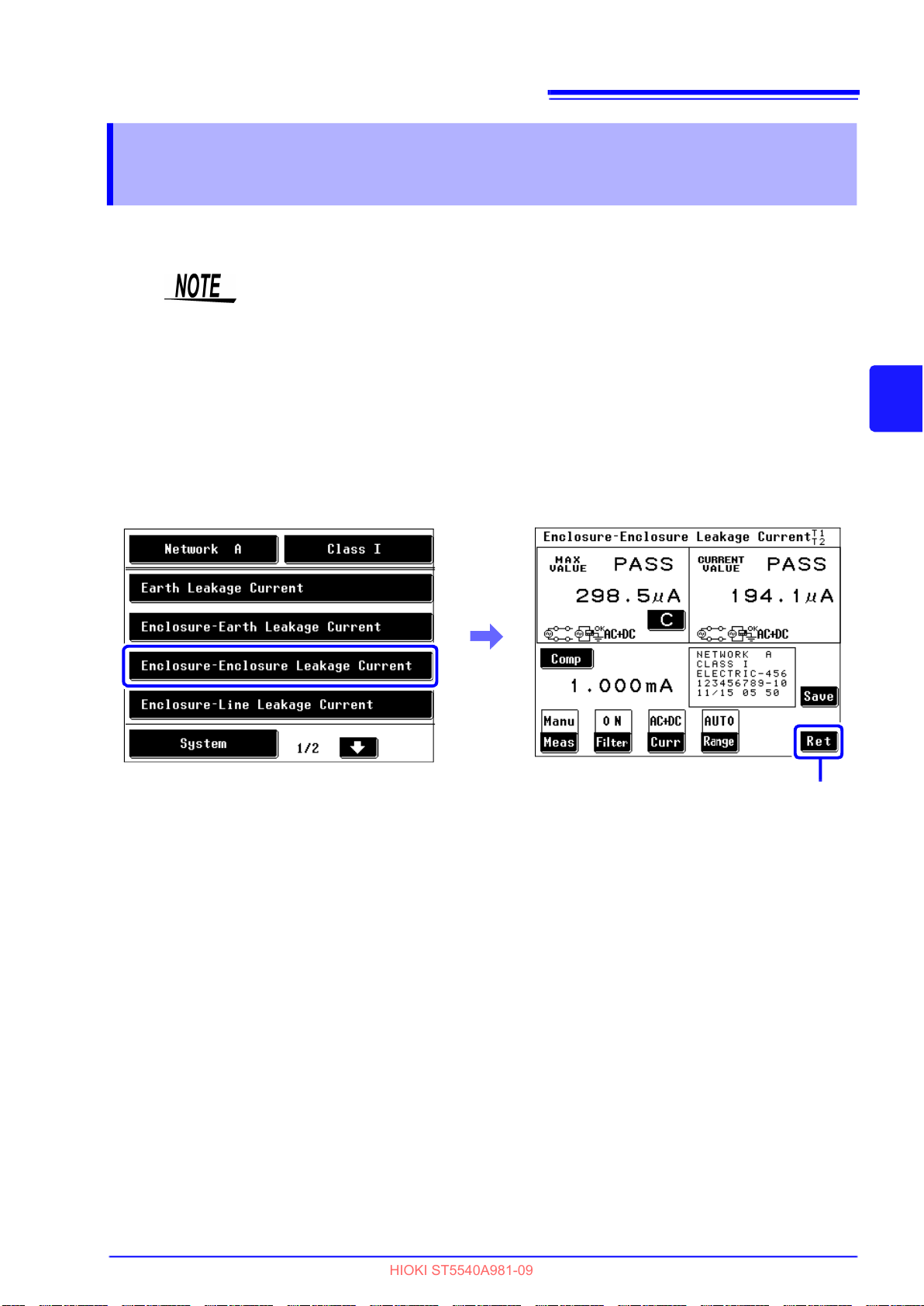
4.3 Selecting a Measurement Mode (opens the measurement screen)
HIOKI ST5540A981-09
4.3 Selecting a Measurement Mode
(opens the measurement screen)
To use the instrument as a voltmeter or measure protective conductor current, see "Chapter 7 Instrument
System Settings" (p. 115).
After a measurement mode is selected on the initial screen, the measurement screen appears.
• The number of measurement modes displayed on the screen varies depend-
ing on the network and class settings selected.
• Some measurement modes may not be available for selection depending on
the class and applied part settings.
• When power on polarity switching is set to On, a power on check is performed
before a measurement screen appears. If the result of the power on check is
NG, press “Yes” to return to the leakage current mode selection screen to
check connections again.
Example : Selecting measurement mode (Enclosure-Enclosure leakage current) in the initial screen.
(network A)
51
3
4
Chapter 4 Settings
Return to initial screen.
52
HIOKI ST5540A981-09
4.3 Selecting a Measurement Mode (opens the measurement screen)
Selectable measurement modes
When selecting network A
Grounding class
Measurement mode
Earth leakage current
Enclosure - Earth leakage current
Enclosure - Enclosure
leakage current
Enclosure - Line leakage current
Free current
Class-I equipment Class-ll equipment
When selecting network C or G
Grounding class
Measurement mode
Earth leakage current
Touch current (Enclosure - Earth)
Touch current
(Enclosure - Enclosure)
Touch current (Enclosure - Line)
Class-I equipment Class-ll equipment
Internally powered
equipment
– –
–
: Can be set, – : Cannot be set
Internally powered
equipment
– –
–
: Can be set, – : Cannot be set
When selecting network D, E or F
Grounding class
Class-I equipment Class-ll equipment
Measurement mode
Earth leakage current
Enclosure - Earth leakage current
Enclosure - Enclosure
leakage current
Enclosure - Line leakage current
Internally powered
equipment
– –
–
: Can be set, – : Cannot be set

4.3 Selecting a Measurement Mode (opens the measurement screen)
HIOKI ST5540A981-09
When selecting network B1
Grounding class
Class-I equipment Class-ll equipment
53
Internally powered
equipment
Measurement mode
applied part
Earth leakage current – – – – – –
Enclosure - Earth
leakage current
Enclosure - Enclosure
leakage current
Patient auxiliary current
Patient leakage current I
Patient leakage current II – – – – – –
Patient leakage current III – – –
Free current
Type BType BFType CFType BType BFType CFType BType BFType
: Can be set, – : Cannot be set
When selecting network B2
Grounding class
Measurement mode
Class-I equipment Class-ll equipment
Type BType BFType CFType BType BFType CFType BType BFType
applied part
Earth leakage current – – – – – –
Touch current (Enclosure - Earth)
Touch current (Enclosure - Enclosure)
Patient auxiliary current
Patient leakage current
(Patient connection - Earth)
Patient leakage current
(external voltage on a SIP/SOP)
Patient leakage current
(external voltage on a specific F-type
applied part)
Patient leakage current
(external voltage on metal accessible
part not protectively earthed)
Total patient leakage current
(Patient connection - Earth)
Total patient leakage current
(external voltage on a SIP/SOP)
Total patient leakage current
(external voltage on a specific F-type
applied part)
Total patient leakage current
(external voltage on metal accessible
part not protectively earthed)
Free current
– – –
– – –
– – –
– – –
Internally powered
equipment
CF
3
4
Chapter 4 Settings
CF
: Can be set, – : Cannot be set

54
HIOKI ST5540A981-09
4.4 Setting the Measurement Range (Auto/Hold)
4.4 Setting the Measurement Range
(Auto/Hold)
Select auto range for automatic range selection. Selecting hold range allows the user to specify one of
four ranges.
When using the Hold range, if you cannot have the faintest idea about the current type and size, please
measure it by "AC+DC" to have a rough idea and decide the measurement range.
Note that the instrument may be damaged if the applied current exceeds the
measurement range.
• Any input that exceeds the indication range is indicated as "OVER FLOW".
• The maximum indication value differs for network D,F and G.
(The range name indicated is the name of the representative network whose
basic element is 1 k
• The minimum indication value in the Hold range setting varies depending on
the network selected.
• The range configuration differs only when the target current is set to "ACPeak."
.)
• Caution on using the Hold range
When "!" is displayed and then a lower sensitivity range is chosen, the judgement result may be out of the guaranteed accuracy range.
See "About Peak Over "!"" (p. 58)
• As for ACPeak measurement, please set the allowable value to a bigger one
than the minimum indication value in the range.
Setting a value less than the minimum indication value disables any numeric
comparison,displayed "Comp Low, Range Down" and setting a value bigger
than the maximum indication value,displayed "Range Up."
See Range of indication:
"Ammeter mode/unit of indication : AUTO range of indication" (p. 55)
See "Ammeter mode/unit of indication : mA (HOLD) range of indication" (p. 57)
• The auto range is not available when a 0.1 Hz frequency range setting is
made. Selecting auto range automatically sets the hold range
(during AC peak measurements: 1.000 mA range; during AC/DC/AC+DC measurements: 500.0 A range).

4.4 Setting the Measurement Range (Auto/Hold)
HIOKI ST5540A981-09
1. On the measurement screen, press to display the measurement range setting screen.
Select a measurement range.
Sets the current range to the Auto
(automatic) range.
Sets the current range to the Hold
(fixed) range.
55
3
4
2. Selecting the Hold range displays a set of range setting keys.
Use these keys to select a range.
When setting the target current to
AC, DC, or AC+DC
Sets the fixed 50 mA range.
When setting the target current to
Sets the fixed 75 mA range.
Chapter 4 Settings
AC Peak
3. Press to return to the measurement screen.
Ammeter mode/unit of indication : AUTO range of indication
Sets the fixed 5 mA range.
Sets the fixed 500 A range.
Sets the fixed 50 A range.
The "fixed 500 A range" is selected in this
screen.
Sets the fixed 10 mA range.
Sets the fixed 1 mA range.
Sets the fixed 500 A range.
The "fixed 1 mA range" is selected in this
screen.
56
HIOKI ST5540A981-09
4.4 Setting the Measurement Range (Auto/Hold)
Range of indication depends on selected unit of indication.
See "7.1 Setting the Mode (Using the instrument as a voltmeter / measuring protective conductor current)" (p. 117)
See For details of accuracy guaranteed range: "10.4 Accuracy" (p. 260)
See "7.10 Setting Indication Unit" (p. 134)
When selecting network A, B1, B2, C, E, or G
(Measurement of AC, DC, or AC+DC)
Range 50.00 mA 5.000 mA 500.0 A 50.00 A
Maximum indication value
to
Minimum indication value
(In Hold range setting)
(Measurement of ACPeak)
Range 75.0 mA 10.00 mA 1.000 mA 500.0 A
Maximum indication value
to
Minimum indication value
(In Hold range setting)
50.00 mA
0.00 mA
(0.00 mA)
75.0 mA
0.0 mA
(0.0 mA
|
|
or less)
5.000 mA
0.000 mA
(0.000 mA)
10.00 mA
0.00 mA
(0.00 mA
|
|
or less)
500.0 A
0.0 A
(0.0 A)
1.000 mA
0.000 mA
(0.000 mA
|
|
or less)
50.00 A
|
1.01 A
(0.00 A)
500.0
A
|
1.1
A
(0.0
A)
When selecting network D
(Measurement of AC, DC, or AC+DC)
Range 50.00 mA 5.000 mA 500.0 A 50.00 A
Maximum indication value
to
Minimum indication value
(In Hold range setting)
33.00 mA
|
0.00 mA
(0.00 mA)
(Measurement of ACPeak)
Range 75.0 mA 10.00 mA 1.000 mA 500.0 A
Maximum indication value
to
Minimum indication value
(In Hold range setting)
50.00 mA
|
0.0 mA
(0.0 mA or less)
When selecting network F
(Measurement of AC, DC, or AC+DC)
Range 50.00 mA 5.000 mA 500.0 A 50.00 A
Maximum indication value
to
Minimum indication value
(In Hold range setting)
25.00 mA
|
0.00 mA
(0.00 mA)
3.300 mA
|
0.000 mA
(0.000 mA)
6.60 mA
|
0.00 mA
(0.00 mA or less)
2.500 mA
|
0.000 mA
(0.000 mA)
330.0 A
|
0.0 A
(0.0 A)
0.660 mA
|
0.000 mA
(0.000 mA or less)
250.0 A
|
0.0 A
(0.0 A)
33.00 A
|
1.01 A
(0.00 A)
330.0 A
|
1.1 A
(0.0 A)
25.00 A
|
1.01 A
(0.0 A)
(Measurement of ACPeak)
Maximum indication value
Minimum indication value
(In Hold range setting)
Range 75.0 mA 10.00 mA 1.000 mA 500.0 A
to
37.5 mA
|
0.0 mA
(0.0 mA or less)
5.00 mA
|
0.00 mA
(0.00 mA or less)
0.500 mA
|
0.000 mA
(0.000 mA or less)
250.0 A
|
1.1 A
(0.0 A)

4.4 Setting the Measurement Range (Auto/Hold)
HIOKI ST5540A981-09
Ammeter mode/unit of indication : mA (HOLD) range of indication
Sets the unit of current measurement to mA.
See "7.1 Setting the Mode (Using the instrument as a voltmeter / measuring protective conductor current)" (p. 117)
See For details of accuracy guaranteed range:"10.4 Accuracy" (p. 260)
See "7.10 Setting Indication Unit" (p. 134)
When selecting network A, B1, B2, C, E, or G
(Measurement of AC, DC, or AC+DC)
Range 50.00 mA 5.000 mA 500.0 A 50.00 A
Maximum indication value
to
Minimum indication value
(In Hold range setting)
50.00 mA
|
0.00 mA
(0.00 mA)
5.000 mA
|
0.000 mA
(0.000 mA)
0.500 mA
|
0.000 mA
(0.000 mA)
0.050 mA
|
0.002 mA
(0.000 mA)
57
3
(Measurement of ACPeak)
Range 75.0 mA 10.00 mA 1.000 mA 500.0 A
Maximum indication value
to
Minimum indication value
(In Hold range setting)
75.0 mA
|
0.0 mA
( 0.0 mA or less)
When selecting network D
(Measurement of AC, DC, or AC+DC)
Range 50.00 mA 5.000 mA 500.0 A 50.00 A
Maximum indication value
to
Minimum indication value
(In Hold range setting)
33.00 mA
|
0.00 mA
(0.00 mA)
(Measurement of ACPeak)
Range 75.0 mA 10.00 mA 1.000 mA 500.0 A
Maximum indication value
to
Minimum indication value
(In Hold range setting)
50.0 mA
|
0.0 mA
(0.0 mA or less)
10.00 mA
|
0.00 mA
(0.00 mA or less)
3.300 mA
|
0.000 mA
(0.000 mA)
6.60 mA
|
0.00 mA
(0.00 mA or less)
1.000 mA
|
0.000 mA
(0.000 mA or less)
0.330 mA
|
0.000 mA
(0.000 mA)
0.660 mA
|
0.000 mA
(0.000 mA or less)
4
Chapter 4 Settings
0.500 mA
|
0.002 mA
(0.000 mA)
0.033 mA
|
0.002 mA
(0.002 mA)
0.330 mA
|
0.002 mA
(0.000 mA)
When selecting network F
(Measurement of AC, DC, or AC+DC)
Maximum indication value
Minimum indication value
(Measurement of ACPeak)
Maximum indication value
Minimum indication value
Range 50.00 mA 5.000 mA 500.0 A 50.00 A
to
(In Hold range setting)
Range 75.0 mA 10.00 mA 1.000 mA 500.0 A
to
(In Hold range setting)
25.00 mA
|
0.00 mA
(0.00 mA)
37.5 mA
|
0.0 mA
(0.0 mA or less)
2.500 mA
|
0.000 mA
(0.000 mA)
5.00 mA
|
0.00 mA
(0.00 mA or less)
0.250 mA
|
0.000 mA
(0.000 mA)
0.500 mA
|
0.000 mA
(0.000 mA or less)
0.025 mA
|
0.002 mA
(0.000 mA)
0.250 mA
|
0.002 mA
(0.000 mA)

58
HIOKI ST5540A981-09
4.4 Setting the Measurement Range (Auto/Hold)
About Peak Over "!"
•
When measuring in Hold
(fixed) range setting, if a portion of measuring current goes
over the input allowable range
for the circuit, "!" together with
"
FAIL
" may be displayed on
the measuring screen. "!"
means that some of the instantaneous values go over the
input allowable range. In this
case, please select a lower
sensitivity range to measure.
• When measuring in Auto
(automatic) range, if some of the instantaneous values goes over the input
allowable range and then a lower sensitivity range is chosen, the judgement
result may be out of the guaranteed accuracy range.
•
"!" will be displayed only in ammeter mode and not in voltmeter mode. "!" information is not available for RS-232C or GP-IB communication or printers. In case
of displaying "!", "
• An error screen like the one
shown in the figure appears
when an excessive current input
is made to the instrument.
Check the equipment under test
and the wiring and press the
"Ret" key.
OVER FLOW
" and "
Range Up" will also be displayed.
!
You must press the to
start operation.

4.5 Setting the Filter
HIOKI ST5540A981-09
4.5 Setting the Filter
(when selecting network A, B1, B2 or C)
Turn the filter for the measurement network ON and OFF or change the setting of the filter.
In manual measurement, the measurement value can be checked while switching the filter ON and OFF.
When selecting network A , B1 or B2 :The filter is switched ON and OFF.
When selecting network C
When selecting network D, E, F or G
When selecting network A
:The filter is set to ON1-U2/ON1 -
U1/ON2-U3/ON2-U1 or OFF.
: No setting for filter.
59
3
4
Chapter 4 Settings
When selecting network B1, B2
1. On the measurement screen, press to
display the network filter setting screen.
2. Change the setting of the filter for the network.
Sets the multi-frequency network.
Sets the single-frequency network.
3. Press to return to the measurement screen.
1. On the measurement screen, press to dis-
play the network filter setting screen.
2. Change the setting of the filter for the network.
Sets the network with a frequency
characteristic.
Sets the network with only 1 k
non-inductive resistance.
3. Press to return to the measurement screen.

60
HIOKI ST5540A981-09
4.5 Setting the Filter
When selecting network C
1. On the measurement screen, press to
display the network filter setting screen.
2. Change the setting of the filter for the network.
Sets a network compatible with
perception/reaction.
Sets a network compatible with
abandonment.
Sets the body impedance network.
See "Network C (for IEC 60990)" (p. 274)
3. Press to return to the measurement screen.

4.6 Setting the Allowable Value
HIOKI ST5540A981-09
4.6 Setting the Allowable Value
Set the allowable value (upper-limit leakage current value) for the measurement value and maximum
value.
According to the status (normal condition, single-fault condition) of the equipment under test, two values
can be set.
The allowable value setting is based on "Numeric value x Factor."
Use the allowable value setting to provide a margin or compensate for measurement error.
The factor is set to "100%" by default. (Input range 1 to 100% )
Set a lower limit value when required.
• Setting a lower limit value for all measurement modes.
See "7.9 Setting Lower Limit Values (factor)" (p. 133)
• Setting a lower limit value for specific measurement modes.
See "Turning lower limit values on and off for specific leakage current measurements" (p. 63)
The instrument indicates the result (PASS/FAIL/LOW indication) of comparison between the measurement value and allowable value.
In automatic measurement, the judgement result is output from EXT I/O.
See "9.2 Connecting to the EXT I/O Terminal" (p. 249)
61
3
4
Chapter 4 Settings
The buzzer that sounds based on the judgement result can be disabled.
See "7.13 Setting the Beep Sound" (p. 138)

62
HIOKI ST5540A981-09
4.6 Setting the Allowable Value
2
3
1. On the measurement screen, press to
display the allowable value setting screen.
2. Press to activate the allowable value
setting condition for normal condition.
4
Allowable value setting screen
(Normal condition, numeric value setting mode)
5
6
7
Allowable value setting screen
(Normal condition, factor setting mode)
3. Enter a numeric value by using numeric keys
( through , and ).
To correct an input error, press the Clear
( ) key, then reenter the input.
4. Enter the unit of allowable value.
Pressing a Unit key ( , ) immediately confirms the numeric input.
5. Press to set factor setup status for set
allowable value.
6. Enter a numeric value by using numeric keys
( through ).
To correct an input error, press the Clear
( ) key, then reenter the input.
7. Pressing the Unit key ( ) immediately
confirms the factor input.
(fault condition, numeric value setting mode)
8
10
Allowable value setting screen
8. Press to activate the allowable value
setting condition for fault condition.
9. In the same way as for setting the normal con-
dition, make the necessary settings by following steps 3 through 7.
10. Press to return to the measurement
screen.

63
HIOKI ST5540A981-09
4.6 Setting the Allowable Value
• The allowable value setting range is from 5 A to 50 mA.
If a value less than 5 A is entered, the setting is automatically adjusted to "5
A."
If a value greater than 50 mA is entered, the setting is automatically adjusted
to "50 mA."
• If the screen is changed without pressing , or , the new
allowable value setting does not take effect.
• The Unit keys ( , , ) cannot be operated until a numeric key is
pressed.
About allowable value judgement
When the indication unit is fixed to "mA," FAIL judgement may result even if
the measurement value (or maximum value) and allowable value are the
same. This is because internally retained data contains lower-order digits
even if the unit is fixed to "mA," and judgement is made using the values with
lower-order digits.
An allowable value setting lower than the accuracy guarantee range, displayed "Comp Low".
Turning lower limit values on and off for specific leakage current
measurements
Use the functions below to turn the lower limit value on
or off for specific measurements.
Press to turn the lower limit value on.
Press to turn the lower limit value off.
3
4
Chapter 4 Settings
This screen allows you only to turn lower limit values On or Off.
Use the System settings (p. 133) to change coefficients for lower limit values or
turn on or off all lower limit values.
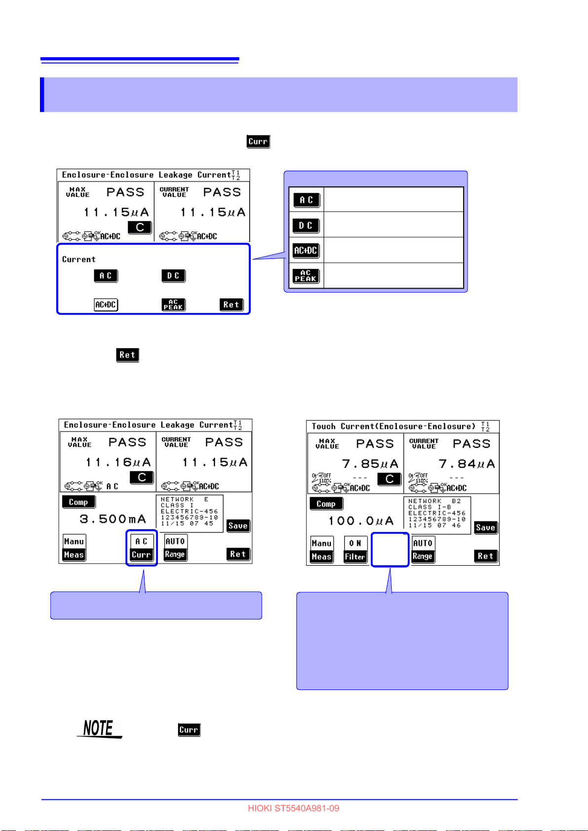
64
HIOKI ST5540A981-09
4.7 Selecting the Type of Target Current
4.7 Selecting the Type of Target Current
1. On the measurement screen, press to display the target current setting screen.
Select the type of target current.
For AC measurement
For DC measurement
For AC + DC measurement
For AC peak measurement
Auxiliary current setting screen
2. Press to return to the measurement screen.
Measurement screen
In the diagram, the target current is set to "AC"
(alternating current).
Measurement screen
(When selecting network B1 or B2)
When network B1 or B2 is selected, some
measurement modes do not permit measurement current settings and can therefore not
indicate current and current setting conditions.
Only measurement modes involving multiple
auxiliary currents are displayed to enable
selection of auxiliary current.
See "Selectable target currents" (p. 65)
appears on the measurement screen only when selection of auxiliary
current is enabled.

Selectable target currents
HIOKI ST5540A981-09
65
4.7 Selecting the Type of Target Current
Network
Measurement mode
Earth leakage current
Enclosure - Line
leakage current
Enclosure - Earth
leakage current
Enclosure - Enclosure
leakage current
Free current
Measurement mode
Earth leakage current
Touch current
(Enclosure - Line)
Touch current
(Enclosure - Earth)
Touch current
(Enclosure - Enclosure)
Patient auxiliary current
Patient leakage current
(Patient connection - Earth)
* B1:Patient leakage current I
Patient leakage current
(external voltage on a SIP/SOP)
* B1:Patient leakage current II
Patient leakage current
(external voltage on a specific
F-type applied part)
* B1:Patient leakage current III
Network
A D E F
AC
DC
AC+DC
AC
DC
AC+DC
AC
DC
AC+DC
AC
DC
AC+DC
AC
DC
AC+DC
ACPeak
AC
DC
AC+DC
ACPeak
AC
DC
AC+DC
ACPeak
AC
DC
AC+DC
ACPeak
AC
DC
AC+DC
ACPeak
– – –
:
B1 B2 C G
AC+DC
AC+DC
– –
AC+DC
AC+DC
AC
DC
AC
DC
AC+DC
AC+DC
AC+DC
AC+DC
AC
DC
AC
DC
AC
DC
AC+DC
AC
DC
AC+DC
ACPeak
AC
DC
AC+DC
ACPeak
AC
DC
AC+DC
ACPeak
AC
DC
AC+DC
ACPeak
Cannot be set –: Not applicable
AC
DC
AC+DC
ACPeak
AC
DC
AC+DC
ACPeak
AC
DC
AC+DC
ACPeak
AC
DC
AC+DC
ACPeak
– –
– –
– –
– –
AC
DC
AC+DC
ACPeak
AC
DC
AC+DC
ACPeak
AC
DC
AC+DC
ACPeak
AC
DC
AC+DC
ACPeak
AC
DC
AC+DC
ACPeak
AC
DC
AC+DC
ACPeak
AC
DC
AC+DC
ACPeak
AC
DC
AC+DC
ACPeak
3
4
Chapter 4 Settings
: Cannot be set –: Not applicable

66
HIOKI ST5540A981-09
4.7 Selecting the Type of Target Current
Network
Measurement mode
Patient leakage current
(external voltage on metal accessible part
not protectively earthed)
Total patient leakage current
(Patient connection - Earth)
Total patient leakage current
(external voltage on a SIP/SOP)
Total patient leakage current
(external voltage on
a specific F-type applied part)
Total patient leakage current
(external voltage on metal accessible part
not protectively earthed)
Free current
B1 B2 C G
–
–
–
–
–
AC+DC
AC
DC
AC
DC
AC+DC
AC+DC
– –
– –
– –
– –
– –
×
AC
DC
AC+DC
ACPeak
AC
DC
AC+DC
ACPeak
– –
Cannot be set –: Not applicable
:

4.8 Changing the Measurement Method (Auto/Manual)
HIOKI ST5540A981-09
4.8 Changing the Measurement Method
(Auto/Manual)
(1) Manual measurement
The measurement value can be checked while changing the target current, filter setting, power
supply polarity, and equipment status.
(2) Automatic measurement
The power supply polarity and equipment status are automatically switched during measurement.
The item to be switched automatically can be selected and the measuring time set.
67
3
1. On the measurement screen, press to display the manual/auto measurement setting
screen.
1
2. Select a measurement mode.
For manual measurement
For automatic measurement
4
Chapter 4 Settings
Setting screen
(Manual measurement)
Measurements start when measurement is set to "Manual" in the measurement screen. Measurement
conditions can be changed during ongoing measurements. Continue to "Chapter 5 Measurement Preparations" (p. 75).
Make the following settings to make automatic measurements.
Return to
measurement
screen.
Setting screen
(Automatic measurement)
Return to
measurement
screen.

68
HIOKI ST5540A981-09
4.8 Changing the Measurement Method (Auto/Manual)
Setting automatic measurement items
The selected network, class and measurement mode determine what measurement items will appear.
See Appendix2 "List of instrument status, other test condition and special test condition"(p.A4)
1. On the automatic measurement setting screen, press to display the automatic measure-
ment item setting screen.
2. Turn automatic measurement for each measurement item ON or OFF.
Each time a key is pressed, the indication switches between ON and OFF.
ON : Sets automatic
1
2
measurement item.
OFF : Does not set
automatic measurement item.
Return to setting screen.
1. Power supply polarity
Indicates "positive phase."
Indicates "negative phase."
Equipment with an internal power supply cannot be set.
See "Line phase in leakage current measurement
between enclosure and line" (p. 69)
2.Condition of equipment under test
(power supply)
Sets "Normal condition."
Sets a "Single fault condition"
(power supply lead is disconnected).
Sets a "Single fault condition"(protective
earth terminal is disconnected).
Other conditions
Applies a voltage to the L line.
Applies a voltage to the N line.
Sets application of 110% of voltage,
1
*
positive phase.
(When selecting network B1.)
Sets application of 110% of voltage,
1
*
negative phase.
(When selecting network B1.)
Automatic measurement item setting screen
Other test condition (Other applied voltages)*
1
Sets application of 110% of voltage,
*
positive phase.
1
Sets application of 110% of voltage,
*
negative phase.
Sets application of 110% of voltage, OFF.
See "Measurement with 110% voltage application (Other
test condition)" (p. 69)
2
Special test condition
(Specific applied voltage)*
1
Sets application of 110% of voltage,
*
positive phase.
1
Sets application of 110% of voltage,
*
negative phase.
See "Measurement with 110% voltage application (Special
test condition)" (p. 69)
2
Target current
Measurement current can be selected when automatic
measurement item is selected only when network B1 or B2
is selected and patient leakage current I mode, patient leakage current (Patient connection - Earth) or patient auxiliary
current is also selected. (In any other mode, AC + DC is
automatically selected and cannot be changed)
Sets AC measurement.
Sets DC measurement.
1
*
The "N" key indicates positive phase and "R" negative
phase.
2
*
When selecting network B2.
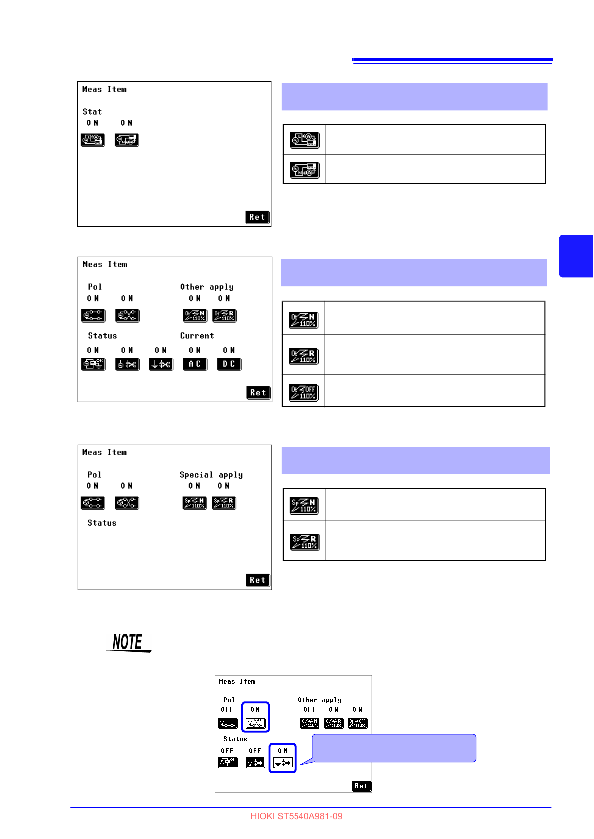
4.8 Changing the Measurement Method (Auto/Manual)
HIOKI ST5540A981-09
EX.:Automatic measurement item setting
measurement between enclosure and line
69
Line phase in leakage current measurement between
enclosure and line
Shown when network A, C, D, E, F or G is selected.
Measurement with 110% voltage application
(Other test condition)
Shown when network B2 is selected
*
Conducts measurement with voltage of the L
(live) side of power supplied to [LINE IN].
Conducts measurement with voltage of the N
(neutral) side of power supplied to [LINE IN].
Conducts measurement with voltage that is in
*
the same phase as power supplied to [LINE IN].
3
4
Chapter 4 Settings
EX.:Automatic measurement item setting
screen for network B2 and patient leakage
current (SIP/SOP) measurement
EX.:Automatic measurement item setting
screen for network B2 and patient leakage
current (Metal accessible part) measurement
Conducts measurement with voltage that is in
*
the reversed phase of power supplied to [LINE
IN].
Conducts measurement turning off power supply
*
connected to [LINE IN].
These two settings cannot be set to OFF at the same time.
Measurement with 110% voltage application
(Special test condition)
Shown when network B2 is selected
Conducts measurement with voltage that is in
*
the same phase as power supplied to [LINE IN].
Conducts measurement with voltage that is in
*
the reversed phase of power supplied to [LINE
IN].
These two settings cannot be set to OFF at the same time.
*The "N" key indicates positive phase and "R" negative
phase.
All measurement items cannot be turned off.
At least one item must be on.
(An attempt to turn off all items, will cause one item to go on.)
At least 1 item will be on.
It is not possible to turn off all items.
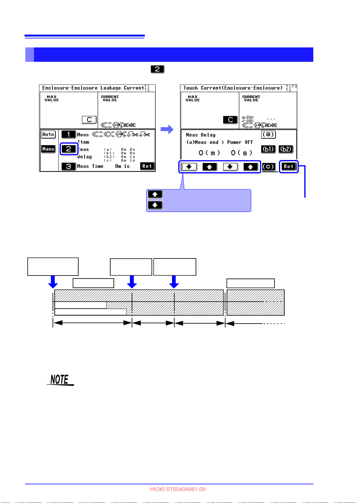
70
HIOKI ST5540A981-09
4.8 Changing the Measurement Method (Auto/Manual)
Setting the measurement delay (delay time)
On the automatic measurement screen, press to display the measurement delay time setting screen.
Automatic measurement item setting screen
Increments the numeric value.
Decrements the numeric value.
Measurement delay time setting screen
Return to Automatic
measurement item
setting screen
Delay times
The figure below shows the relationship between delay times (a), (b1), (b2) and (c) and measurement time.
Start of automatic
measurement
First test item
Auto range operation
15 sec (at a setting of 0.1 Hz)
Delay (b1)+(b2)
or Delay (c)
Start of
measurements
Measurement
End of
measurements
time
Delay (a)
Next test item
Next test item
Delay (b1)+(b2)
or Delay (c)
In the following cases, delay b2 and delay c may last longer than the set delay
time.
• When auto range is set and auto range does not stabilize during the set delay
time, the delay time is extended as required.
• The time-out for auto range is 5 seconds. If the range does not stabilize within
5 seconds, operation is terminated.
• When the frequency range is set to start from 0.1 Hz, 15 sec is added before
measurements start so a measurement setting of less than 15 sec will still
include a 15 sec delay. (Includes a 15 sec delay time)
However, if the delay time is set to 15 sec or longer, that setting will have priority.

4.8 Changing the Measurement Method (Auto/Manual)
HIOKI ST5540A981-09
(a): Setting the time for disconnecting one wire
Use this function to set the time of disconnection of one wire
after the previous measurement ends and before continuing
with the next one when the next measurement is "disconnection of one wire in power cord."
(This time setting gives a connected computer enough time to
shut down before "disconnection of one wire in power cord"
occurs as a sudden shutdown could damage it.)
Press and set Delay (a).
(0 sec. to 30 min. (in 1 sec. increments))
71
3
4
(b1), (b2): Setting polarity switching time
When power on polarity switching is used, the power is not turned off even
during polarity switching and a delay (b1 and b2) need not be set.
Start of polarity
switching
Power off period
Power returns
Delay b1
Delay b1
The power is momentarily turned off when polarity is switched.
Set this delay to prevent damaging equipment by power being
turned off and then immediately being turned back on.
Press and set Delay (b2).
(0 sec. to 30 min. (in 1 sec. increments))
Polarity is
switched
Chapter 4 Settings
Start of
measurements
Delay b2
Delay b2
The power is momentarily turned off when polarity is switched.
Set this delay in turning the power on again after equipment
under test has been turned off.
Press and set Delay (b2).
(1 sec. to 30 min. (in 1 sec. increments))

72
HIOKI ST5540A981-09
4.8 Changing the Measurement Method (Auto/Manual)
(c): Setting the time to start measurements not involving polarity switching
Use this function to set the time for the start of the next measurement under conditions other than (a) and (b).
Set a delay for measurements that does not involve polarity
switching.
Press and set Delay (c).
(1 sec. to 30 min. (in 1 sec. increments))

4.8 Changing the Measurement Method (Auto/Manual)
HIOKI ST5540A981-09
Setting the measuring time
1. On the automatic measurement screen, press to display the measurement time setting
screen.
2. Set the measuring time. (1 sec. to 5 min. (in 1 sec. increments))
73
3
4
Chapter 4 Settings
Automatic measurement item setting screen
If measurement values do not stabilize due to abrupt input fluctuations in the
auto range during automatic measurements, measurements are terminated and
no further measurements are made.
Measuring time setting screen
Increments the numeric value.
Decrements the numeric value.
Status indication of instrument during automatic measurements
During automatic measurements, the item above the
Stop key indicates instrument status.
Displayed items
Time until transition to disconnection of one
wire in power cord
Time until power supply polarity is switched
Time until transition to measurements other
than polarity switching
During measurements

74
HIOKI ST5540A981-09
4.8 Changing the Measurement Method (Auto/Manual)

L
HIOKI ST5540A981-09
Measurement
75
5.1 Connecting the Test Lead
Preparations
Chapter 5
5.1 Connecting the Test Lead
When a measurement mode is selected, the measuring terminals (T1, T2, and T3) to be used for measurement are indicated at the top of the screen.
Connect the test leads based on the indications displayed.
To avoid breaking the test leads, do not bend or pull them.
5
Chapter 5 Measurement Preparations
The list of the measuring terminals to be used
When selecting network A, D, E or F
Class-I equipment Class-II equipment
Earth leakage current
Enclosure - Earth leakage current T2 T2 T2
Enclosure - Enclosure leakage current T1, T2 T1, T2 T1, T2
Enclosure - Line leakage current
(Selected line Internal)
Enclosure - Line leakage current
(Selected line External)
Free current
*
– – –
T2 T2
T1, T2 T1, T2
T1, T2 T1, T2 T1, T2
*
Only network A provides free current
When selecting network C, G
Class-I equipment Class-II equipment
Earth leakage current
Touch current (Enclosure - Earth) T2 T2 T2
Touch current (Enclosure - Enclosure) T1, T2 T1, T2 T1, T2
Touch current (Enclosure - Line)
(Selected line Internal)
Touch current (Enclosure - Line)
(Selected line External)
– – –
T2 T2
T1, T2 T1, T2
Internally powered
Internally powered
equipment
–
–
equipment
–
–

76
HIOKI ST5540A981-09
5.1 Connecting the Test Lead
When selecting network B1
Class-I equipment Class-II equipment
Type B Type BF Type CF Type B Type BF Type CF Type B Type BF Type CF
Earth leakage current
Enclosure - Earth
leakage current
Enclosure - Enclosure
leakage current
Patient auxiliary current T1,T2 T1,T2 T1,T2 T1,T2 T1,T2 T1,T2 T1,T2 T1,T2 T1,T2
Patient leakage current I T2 T2 T2 T2 T2 T2 T1,T2 T1,T2 T1,T2
Patient leakage current II T2,T3
Patient leakage current III
Free current
Normal T2 T2 T2 T2 T2 T2 T2 T2 T2
Fault/
Apply
Normal T1,T2 T1,T2 T1,T2 T1,T2 T1,T2 T1,T2 T1,T2 T1,T2 T1,T2
Fault/
Apply
T2,T3 T2,T3 T2,T3 T2,T3 T2,T3 T2,T3 T2,T3 T2,T3 T2,T3
T1,T2,T3 T1,T2,T3 T1,T2,T3 T1,T2,T3 T1,T2,T3 T1,T2,T3 T1,T2,T3 T1,T2,T3 T1,T2,T3
–
Normal T1,T2 T1,T2 T1,T2 T1,T2 T1,T2 T1,T2 T1,T2 T1,T2 T1,T2
Fault/
Apply
T1,T2,T3 T1,T2,T3 T1,T2,T3 T1,T2,T3 T1,T2,T3 T1,T2,T3 T1,T2,T3 T1,T2,T3 T1,T2,T3
– – –
– –
T2 T2
T2,T3
–
– –
T2 T2
Internally powered equip-
ment
T2,T3
–
– –
T2 T2
When selecting network B2
Class-I equipment Class-II equipment
Type B Type BF Type CF Type B Type BF Type CF Type B Type BF Type CF
Earth leakage current
Touch current
(Enclosure - Earth)
Touch current
(Enclosure - Enclosure)
Patient auxiliary current T1,T2 T1,T2 T1,T2 T1,T2 T1,T2 T1,T2 T1,T2 T1,T2 T1,T2
Patient leakage current
(Patient connection - Earth)
Patient leakage current
(external voltage on a SIP/SOP)
Patient leakage current
(external voltage on a specific
F-type applied part)
Patient leakage current
(external voltage on metal accessi-
ble part not protectively earthed)
Total patient leakage current
(Patient connection - Earth)
Total patient leakage current
(external voltage on a SIP/SOP)
Total patient leakage current
(external voltage on a specific
F-type applied part)
Total patient leakage current
(external voltage on metal accessi-
ble part not protectively earthed)
Free current
Normal T2 T2 T2 T2 T2 T2 T2 T2 T2
Fault/
Apply
Normal T1,T2 T1,T2 T1,T2 T1,T2 T1,T2 T1,T2 T1,T2 T1,T2 T1,T2
Fault/
Apply
T2,T3 T2,T3 T2,T3 T2,T3 T2,T3 T2,T3 T2,T3 T2,T3 T2,T3
T1,T2,T3 T1,T2,T3 T1,T2,T3 T1,T2,T3 T1,T2,T3 T1,T2,T3 T1,T2,T3 T1,T2,T3 T1,T2,T3
T2 T2 T2 T2 T2 T2
T2,T3 T2,T3 T2,T3 T2,T3 T2,T3 T2,T3 T2,T3 T2,T3 T2,T3
– T2 T2 – T2 T2 – T2 T2
T2,T3 T2,T3
T2 T2 T2 T2 T2 T2 T1,T2 T1,T2 T1,T2
T2,T3 T2,T3 T2,T3 T2,T3 T2,T3 T2,T3 T2,T3 T2,T3 T2,T3
–
T2,T3 T2,T3
Normal T1,T2 T1,T2 T1,T2 T1,T2 T1,T2 T1,T2 T1,T2 T1,T2 T1,T2
Fault/
T1,T2,T3 T1,T2,T3 T1,T2,T3 T1,T2,T3 T1,T2,T3 T1,T2,T3 T1,T2,T3 T1,T2,T3 T1,T2,T3
Apply
– – –
T2,T3 T2,T3
T2 T2
–
–
–
T2,T3 T2,T3
T2 T2
–
–
Internally powered
equipment
T1,T2
or T2
T2,T3 T2,T3
T2,T3 T2,T3
T1,T2
or T2
–
T2 T2
T1,T2
or T2
–
–

5.1 Connecting the Test Lead
HIOKI ST5540A981-09
Using L2200 Test Lead
To avoid the risk of electric shock, do not touch the tips of test leads connected to terminals T1, T2, and T3.
In some measurement modes, high voltage is output from the terminals.
Do not touch any part of
the test lead beyond the
finger barrier
Connect the L2200 Test Lead to a measuring terminal (T1, T2, or T3).
The terminal to be used varies depending on the measurement mode.
See"5.1 Connecting the Test Lead" (p. 75)
To apply 110% of rated voltage, use an isolation transformer to supply the voltage to [LINE IN].
The voltage applied to [LINE IN] is also output from the T3 terminal.
77
5
Chapter 5 Measurement Preparations
Using the 9195 Enclosure Probe
(for measuring enclosure leakage current)
When measuring enclosure leakage current, position the surface contact probe on the enclosure of the
equipment under test, then set the test lead on the surface contact probe.
Ensure full contact of the surface contact probe on the enclosure by applying about 0.5 N/cm2 of pressure.
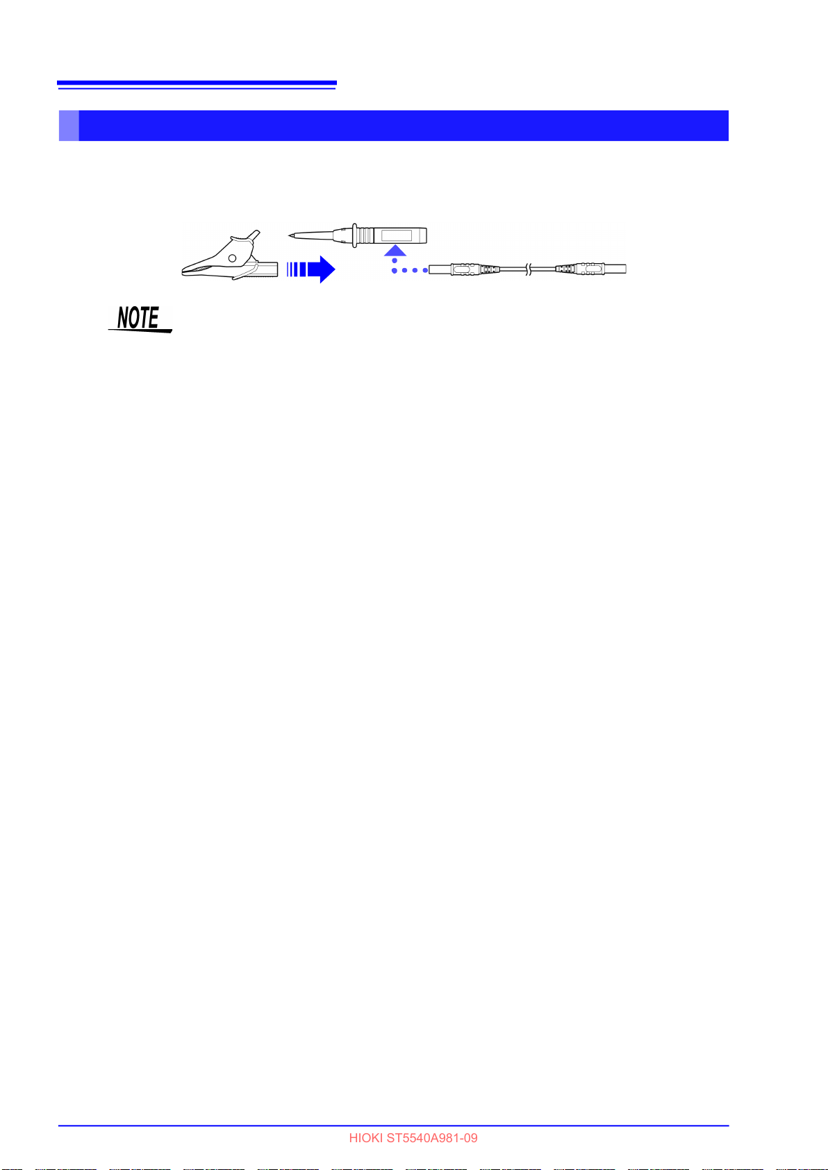
78
HIOKI ST5540A981-09
5.1 Connecting the Test Lead
Using Alligator Clips (when using two or three test leads)
Position the test lead on the enclosure or terminal of the equipment under test to measure leakage current. When using two or three lead wires, alligator clips may be used to ensure a secure connection.
Detach the pin lead from the tip of each L2200 Test Lead and insert the included alligator clip.
]
Pin leads and alligator clips can be connected to either end of the connection
cord.
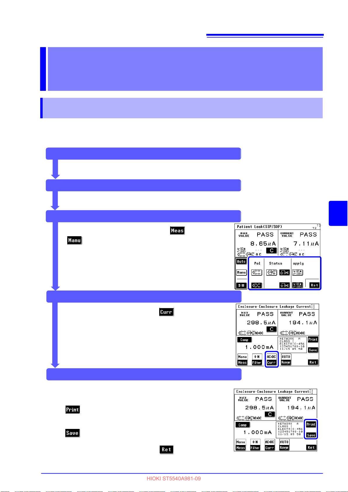
6.1 Making manual measurements
HIOKI ST5540A981-09
Measurements Chapter 6
6.1 Making manual measurements
Free-run measurements start when measurement is set to "Manual" in the measurement screen.
Measurement conditions can be changed during ongoing measurements.
(Manual measurements cannot be made when an internal class is selected.)
Pre-test inspection
Perform a pre-test inspection.
See "3.5 Pre-Test Inspection" (p. 41)
Setup
79
Set up the instrument.
See "Chapter 4 Settings" (p. 47)
During measurements (switching manual measurement item)
On the measurement screen, press and then
to display the manual measurement setting screen.
This allows the user to change power supply polarity and
equipment condition.
The measurement items that appear depend on the
selected network, class and measurement mode.
See "Changing manual measurement items" (p. 80)
During measurements (switching auxiliary current)
On the measurement screen, press to display the target
current setting screen.
This setting allows the user to change the target current.
See "Changing manual measurement items" (p. 80)
The CAL key appears when 0.1 Hz frequency range is set.
See (p. 43)
6
Chapter 6 Measurements
When measurements end, print or save the measurements as
required.
On the measurement screen,
press
See "6.6 Printing Measurement Data (as required)" (p. 108)
On the measurement screen,
press
See "6.4 Saving Measurement Data (As required)" (p. 102)
To repeat automatic measurements, press .
When measurements end
to print the measurement data.
to store the measurement data in internal memory.
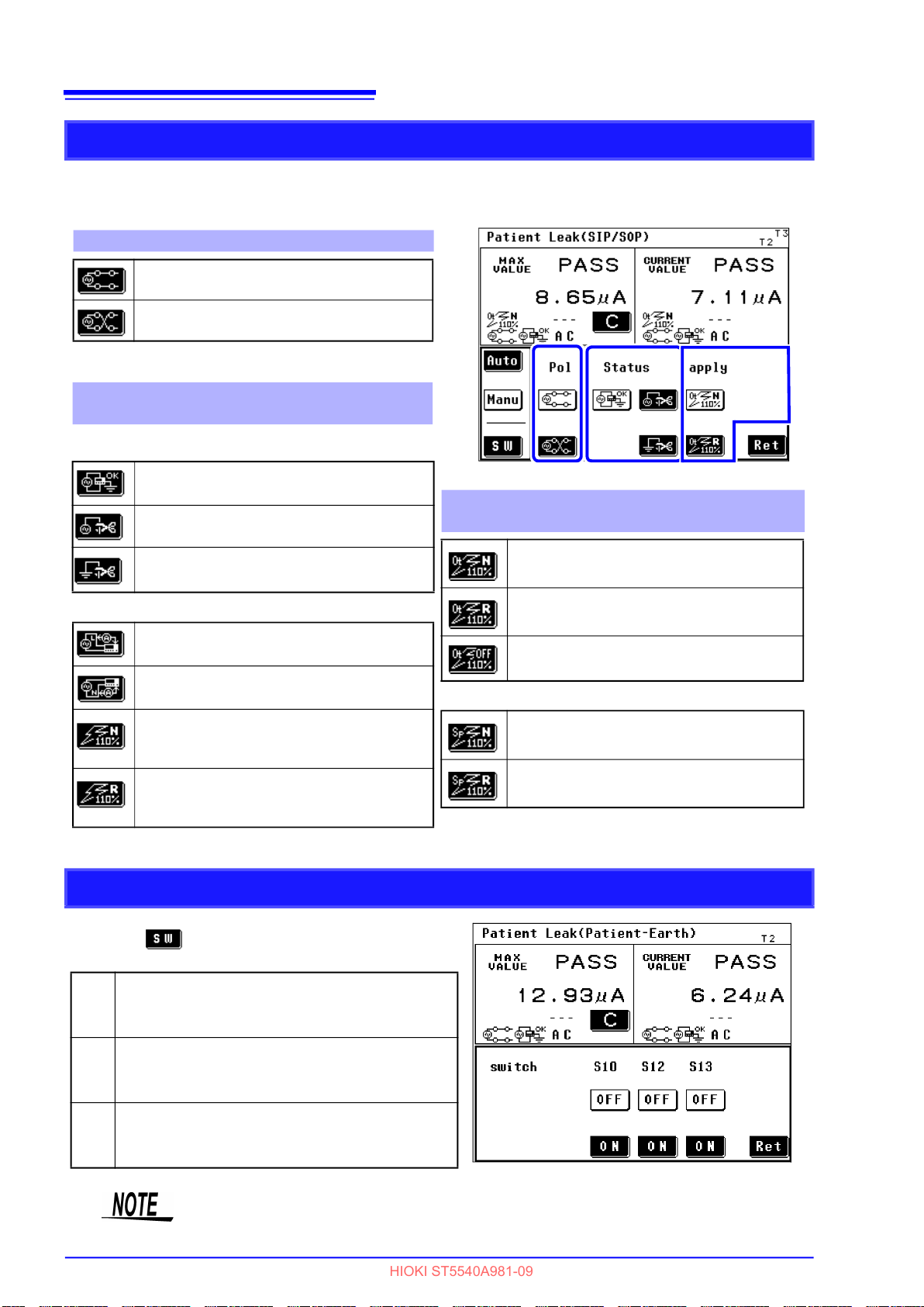
80
HIOKI ST5540A981-09
6.1 Making manual measurements
Changing manual measurement items
The indication varies depending on the network, class setting, and measurement mode selected.
See Appendix2 "List of instrument status, other test condition and special test condition"
(p. A4)
1. Power supply polarity
Indicates "positive phase."
Indicates "negative phase."
Equipment with an internal power supply cannot be
set.
2. State of equipment under test
(power supply)
No equipment whose grounding class is internal can
be set.
Sets "Normal condition."
Sets a "Single fault condition"
(power supply lead is disconnected).
Sets a "Single fault condition"(protective
earth terminal is disconnected).
Other conditions
Sets application of 110% of voltage,
positive phase.
1Sets application of 110% of voltage,
negative phase.
Sets application of 110% of voltage,
*
positive phase.
(When selecting network B1.)
Sets application of 110% of voltage,
*
negative phase.
(When selecting network B1.)
Special test condition (Specific applied voltage)
*
SW status (only network B2 on ST5540)
1
2
3
3. Other test condition (Other applied voltages)
(When selecting network B2.)
*
Sets application of 110% of voltage,
positive phase.
*
Sets application of 110% of voltage,
negative phase.
Sets application of 110% of voltage, OFF.
*
Sets application of 110% of voltage,
positive phase.
*
Sets application of 110% of voltage,
negative phase.
The "N" key indicates positive phase and "R" negative phase.
Pressing in the manual measurement setting
screen opens the switch setting screen.
SW for connecting functional earth terminal and
S10
power supply system for measurement. Set to
On to connect to the LINE IN E terminal.
SW for connecting patient connection to ground
S12
of power supply circuit for measurement. Set to
On to connect to the LINE IN E terminal.
Terminal providing ground connection for metal
S13
accessible part not protectively earthed. Set to
On to connect to the LINE IN E terminal.
For information on connection procedures, refer to (p. 35).
Only manual measurements can be set.

6.1 Making manual measurements
HIOKI ST5540A981-09
Changing measurement current
The indication varies depending on the network, class setting, and measurement mode
selected.
See Appendix2 "List of instrument status, other test condition and special test condition"
(p. A4)
On the measurement screen, press to display
the auxiliary current setting screen.
The following changes can be made.
Target current
Conducts AC measurement.
Conducts DC measurement.
Conducts AC+DC measurement.
(When selection is enabled)
81
Conducts ACPeak measurement.
(When selection is enabled)
6
Chapter 6 Measurements
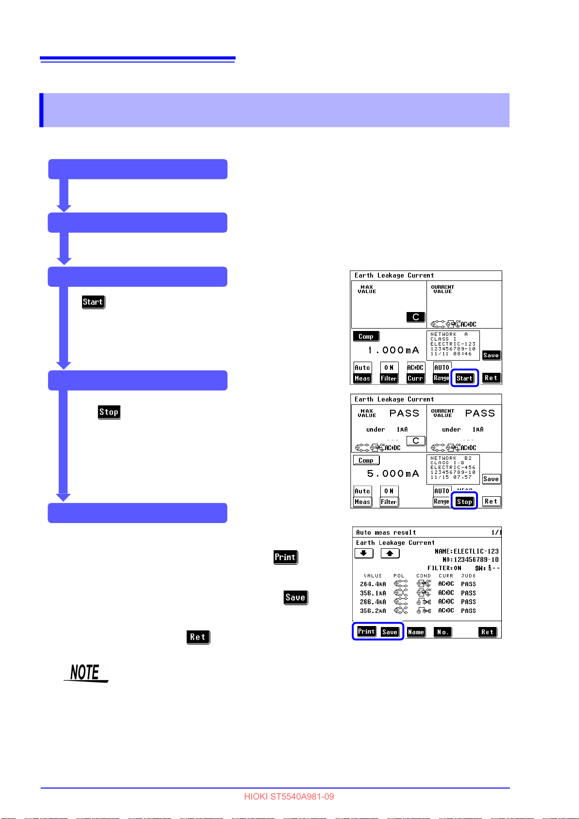
82
HIOKI ST5540A981-09
6.2 Making automatic measurements
6.2 Making automatic measurements
Power supply polarity and equipment status are automatically switched during measurements.
The user can select the measurement items that should be switched and set the measurement time.
Pre-test inspection
Perform a pre-test inspection.
See "3.5 Pre-Test Inspection" (p. 41)
Setup
Set up the instrument.
See "Chapter 4 Settings" (p. 47)
Starting measurements
becomes available in the measurement screen
that appears after settings are completed.
Press to automatically start measurements.
During measurements
Only is available during automatic measurements.
An intermittent beep sound during status measurements. No
beep sound is output at this time when the beep setting for
"key input" is turned off.
See "7.13 Setting the Beep Sound" (p. 138)
When measurements end
When measurements end, print or save the measurements as
required.
On the Automatic measurement result screen, press
measurement data.
See "6.6 Printing Measurement Data (as required)" (p. 108)
On the Automatic measurement result screen, press to store
the measurement data in internal memory.
See "6.4 Saving Measurement Data (As required)" (p. 102)
To repeat measurements, press .
to print the
If measurement values do not stabilize due to abrupt input fluctuations in the
auto range during automatic measurements, measurements are terminated and
no further measurements are made.

6.3 Measurement examples
HIOKI ST5540A981-09
6.3 Measurement examples
Earth leakage current measurement
1. Connect the instrument and the equipment under test.
See "3.3 Connecting equipment under test to the instrument" (p. 36)
2. During manual measurements, Earth leakage current measurement starts upon returning to the
measurement screen.
Measurement conditions can be changed during measurement.
See "6.1 Making manual measurements" (p. 79)
During automatic measurements, becomes available upon return to the measurement
83
screen. Press to start
See "Chapter 4 Settings" (p. 47)
Only is available during automatic measurements.
Earth leakage current measurement.
2
1
6
Chapter 6 Measurements
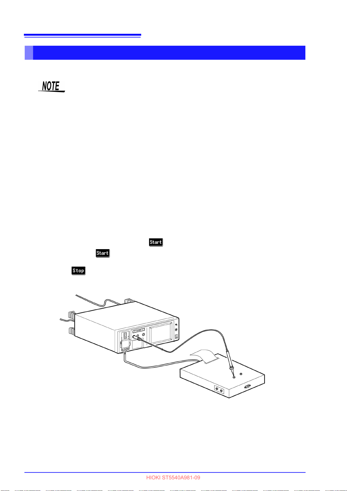
84
HIOKI ST5540A981-09
6.3 Measurement examples
Touch current measurement
Enclosure - Earth measurement
• Conduct leakage current measurement between enclosure and enclosure
using two ungrounded locations on the enclosure.
• The terminal block is not used for internally powered equipment, although
power must be supplied to [LINE IN] by a grounded two-plug power cord.
• When the protective earth conductor is disconnected (single fault), a protec-
tively earthed enclosure is handled as a non-protectively earthed enclosure.
1. Connect the instrument and the equipment under test.
See "3.3 Connecting equipment under test to the instrument" (p. 36)
2. Connect a test lead to terminal T2.
See "5.1 Connecting the Test Lead" (p. 75)
3. Position the tip of the test lead on the enclosure of the equipment under test.
4. During manual measurements, touch current (enclosure - earth) measurement starts upon
returning to the measurement screen.
Measurement conditions can be changed during measurement.
See "6.1 Making manual measurements" (p. 79)
During automatic measurements, becomes available upon return to the measurement
screen. Press to start leakage current measurement between enclosure and earth.
Only is available during automatic measurements.
2
Terminal T2 and enclosure
4
1
3

85
HIOKI ST5540A981-09
6.3 Measurement examples
When network B1 or B2 (Other test condition, Special test condition) is
selected and measurement conducted with 110% voltage application
( , )
• Note that when is pressed in automatic measurement mode, the instru-
ment generates high voltage without displayed on the screen.
• To avoid the risk of electric shock when a test lead is connected to the T3 ter-
minal, do not touch the part of the test lead that is beyond the finger barrier.
The T3 terminal outputs high voltages.
Do not touch any part of
the test lead beyond the
finger barrier
The terminal block is not used for internally powered equipment, although power
must be supplied to [LINE IN] by a grounded two-plug power cord. Also, high
voltage occurring at Terminal T3 depends on this power source.
When the instrument is set to internally powered equipment, do not connect the
equipment under test to an outlet or the terminal block since power is supplied
from an outlet during a 110% voltage application test.
1. Connect the instrument and the equipment under test.
See "3.3 Connecting equipment under test to the instrument" (p. 36)
2. Connect test leads to terminals T2 and T3.
See "5.1 Connecting the Test Lead" (p. 75)
3. Position the tip of the test lead connected to terminal T2 on an ungrounded enclosure section of
the equipment under test.
4. Position the tip of the test lead connected to terminal T3 on an ungrounded signal input section
or signal output section of the equipment under test.
5. During manual measurement, is available upon return to the measurement screen. Press
to start touch current (enclosure - earth) measurement during a single-fault condition.
Pressing applies a high voltage to the test lead connected to the T3 terminal.
Press to terminate output of high voltage.
During automatic measurements, becomes available upon return to the measurement
screen. Press to start touch current (enclosure - earth) measurement under the singlefault condition.
Only is available during automatic measurements.
6
Chapter 6 Measurements
Terminal T3 and I/O terminal
2
5
Terminal T2 and
enclosure
1
3
4

86
HIOKI ST5540A981-09
6.3 Measurement examples
Enclosure - Enclosure measurement
• Conduct leakage current measurement between enclosure and enclosure
using two ungrounded locations on the enclosure.
• The terminal block is not used for internally powered equipment.
• When the protective grounding wire is disconnected (single fault), a protec-
tively earthed enclosure is handled as a non-protectively earthed enclosure.
1. Connect the instrument and the equipment under test.
See "3.3 Connecting equipment under test to the instrument" (p. 36)
2. Connect test leads to terminals T1 and T2.
See "5.1 Connecting the Test Lead" (p. 75)
3. Position the tips of test leads on the enclosure of the equipment under test.
4. During manual measurement, touch current (enclosure - enclosure) measurement starts upon
return to the measurement screen.
Measurement conditions can be changed during measurement.
See "6.1 Making manual measurements" (p. 79)
During automatic measurements, becomes available upon return to the measurement
screen. Press to start touch current (enclosure - enclosure) measurement.
Only is available during automatic measurements.
Terminals T1, T2, and enclosure
2
4
1
3
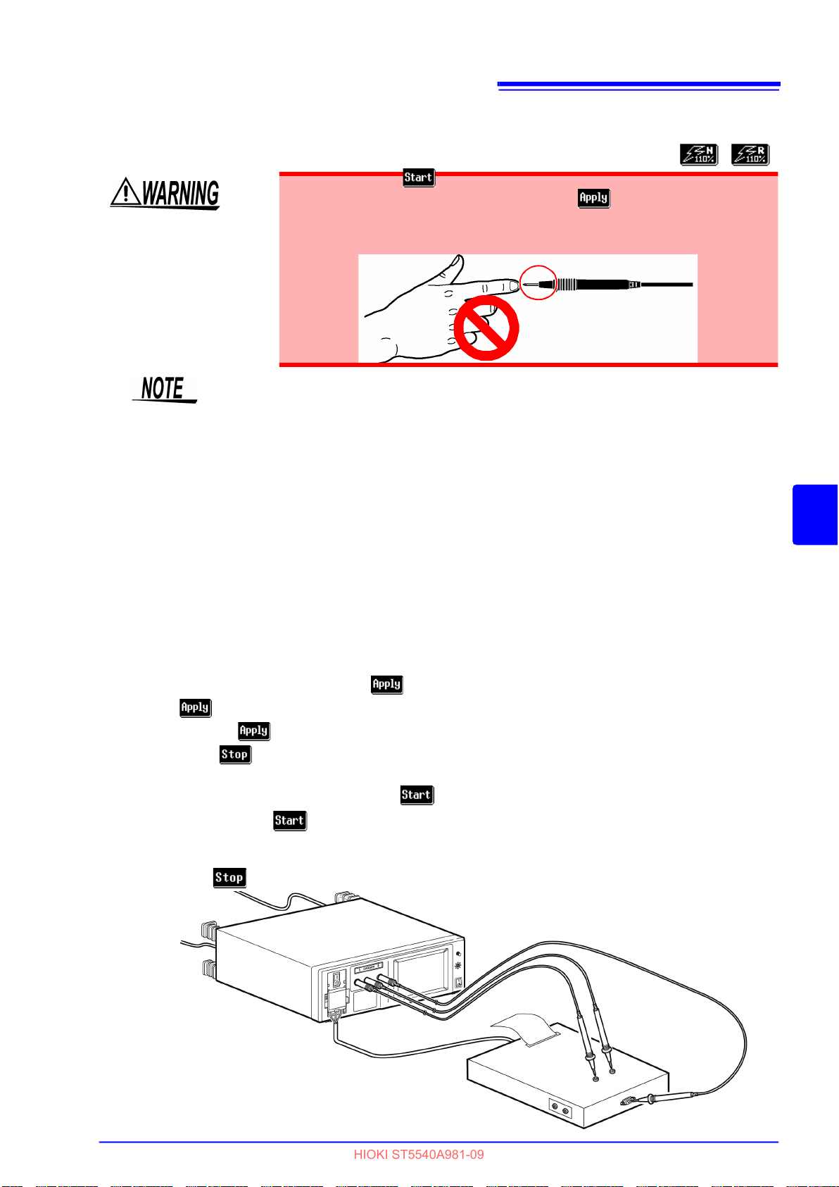
87
HIOKI ST5540A981-09
6.3 Measurement examples
When network B1 or B2 (Other test condition, Special test condition) is
selected and measurement conducted with 110% voltage application
( , )
• Note that when is pressed in automatic measurement mode, the
instrument generates high voltage without displayed on the screen.
• To avoid the risk of electric shock when a test lead is connected to the T3
terminal, do not touch the part of the test lead that is beyond the finger
barrier. The T3 terminal outputs high voltages.
Do not touch any part of
the test lead beyond the
finger barrier
The terminal block is not used for internally powered equipment. However,
power must be supplied to this instrument’s [LINE IN] connector to obtain high
voltage from Terminal T3.
Do not connect the equipment under test to an outlet or the terminal block since
power is supplied from an outlet during a 110% voltage application test.
1. Connect the instrument and the equipment under test.
See "3.3 Connecting equipment under test to the instrument" (p. 36)
2. Connect test leads to terminals T1, T2 and T3.
See "5.1 Connecting the Test Lead" (p. 75)
3. Position the tip of the test lead connected to terminal T1 and T2 on the enclosure of the equip-
ment under test.
4. Position the tip of the test lead connected to terminal T3 on an ungrounded signal input section
or signal output section of the equipment under test.
5. During manual measurement, is available upon return to the measurement screen. Press
to start touch current (enclosure - enclosure) measurement during a single-fault condition.
Pressing applies a high voltage to the test lead connected to the T3 terminal.
Press to terminate output of high voltage.
During automatic measurements, becomes available upon return to the measurement
screen. Press to start touch current (enclosure - enclosure) measurement under the sin-
gle-fault condition.
Only is available during automatic measurements.
6
Chapter 6 Measurements
2
1
Terminal T3 and I/O terminal
5
Terminals T1, T2,
and enclosure
3
4
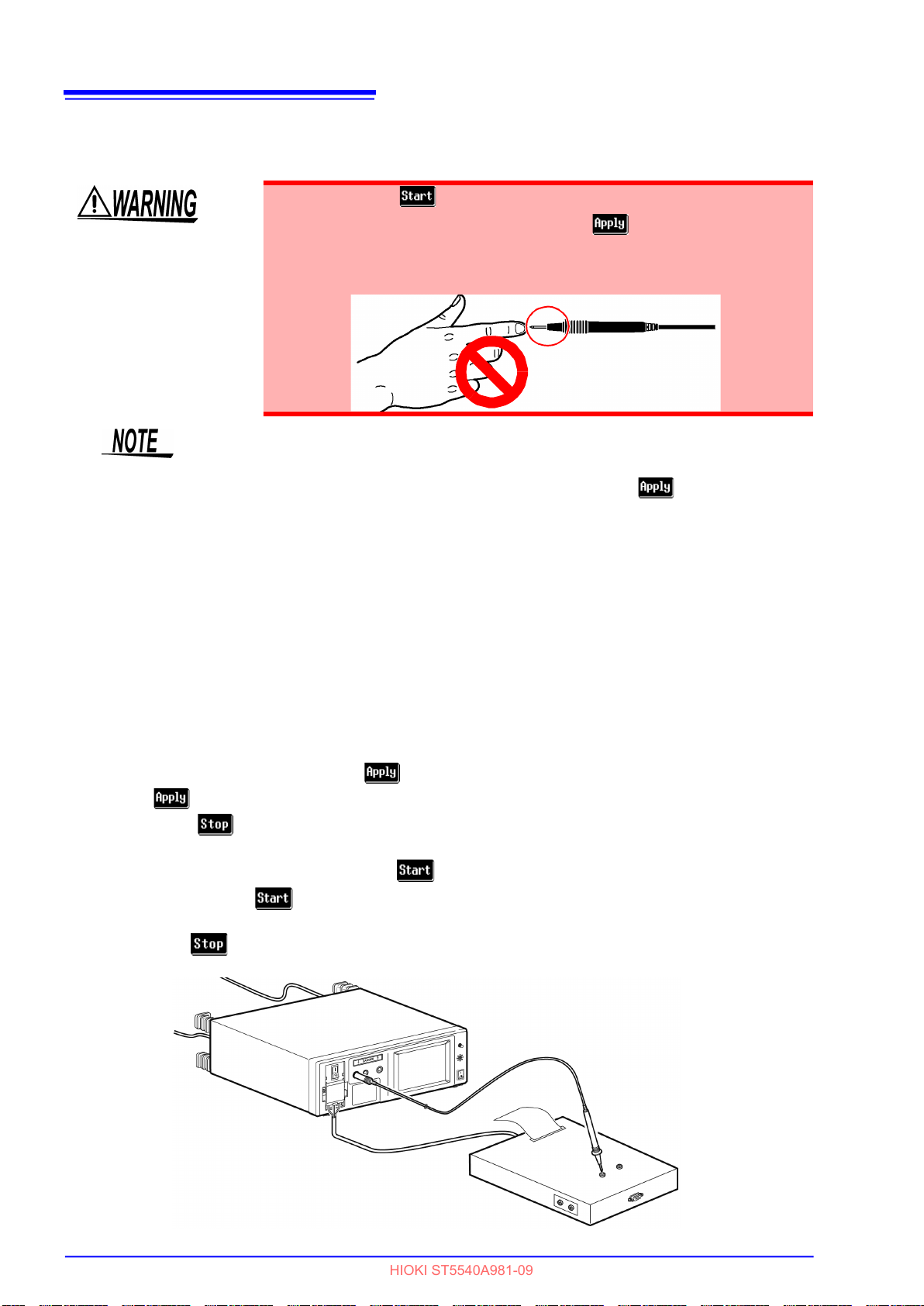
88
HIOKI ST5540A981-09
6.3 Measurement examples
Enclosure - Line measurement*
• Note that when is pressed in automatic measurement mode, the
instrument generates high voltage without displayed on the screen.
• To avoid the risk of electric shock when a test lead is connected to the T2
terminal, do not touch the part of the test lead that is beyond the finger
barrier. The T2 terminal outputs high voltages.
• Conduct leakage current measurement between enclosure and enclosure
using two ungrounded locations on the enclosure.
• A pre-check is made to prevent a ground fault when is pressed.
Measurement ends if the check determines a ground fault has occurred.
• If the probe is brought into contact with protective ground after the pre-check,
a ground fault will occur and the measurement fuse is blown.
• When the protective grounding wire is disconnected (single fault), a protec-
tively earthed enclosure is handled as a non-protectively earthed enclosure.
*
only when selecting a network other than B1 or B2
Do not touch any part of
the test lead beyond the
finger barrier
1. Connect the instrument and the equipment under test.
See "3.3 Connecting equipment under test to the instrument" (p. 36)
2. Connect a test lead to terminal T2.
3. Position the tip of the test lead on the enclosure of the equipment under test.
4. During manual measurement, is available upon return to the measurement screen. Press
to start touch current (enclosure - line) measurement.
Press to terminate output of high voltage.
During automatic measurements, becomes available upon return to the measurement
screen. Press to start touch current (enclosure - line) measurement.
Only is available during automatic measurements.
2
Terminal T2 and enclosure
4
1
3

89
HIOKI ST5540A981-09
6.3 Measurement examples
Application of leakage current measurement between enclosure and line
An equipment under test generating a voltage that exceeds rated capacity* cannot be connected to the
outlet of the instrument (or the terminal block), but the T1 and T2 terminals can be used to measure touch
current (enclosure - line).
*
Rated current : 20 A, rated voltage : 250 V
• Automatic measurement mode cannot be selected.
• The pre-check function is not activated automatically. Therefore, be extra
careful to ensure proper connections. Testing a grounded enclosure section of
the equipment under test will result in a ground fault and blown fuse for measuring operation.
• and are switched for managing saved measurement data.
When data is not saved, measurement may be conducted with either of the
settings described in 4 and 5 above.
• T2 becomes a Hi terminal; T1 becomes a Lo terminal.
1. On the measurement screen, press and
select . The screen for line selection then
appears.
2. Press to set [Use of T1/T2].
3. Connect test leads to terminals T1 and T2.
4. Press to return to the measurement screen.
Connect the tip of the test lead connected to terminal T2 to the L (live) terminal of the power line
for equipment under test.
Connect the tip of the test lead connected to terminal T1 to an ungrounded enclosure section of
the equipment under test.
Read (or save) the measurement data.
5. When is selected, same as 4 above, con-
nect the tip of the test lead connected to terminal
T2 to the N (neutral) terminal of the power line for
equipment under test, then connect the tip of the
test lead connected to terminal T1 to an
ungrounded enclosure section of the equipment
under test.
Read (or save) the measurement data.
6
Chapter 6 Measurements
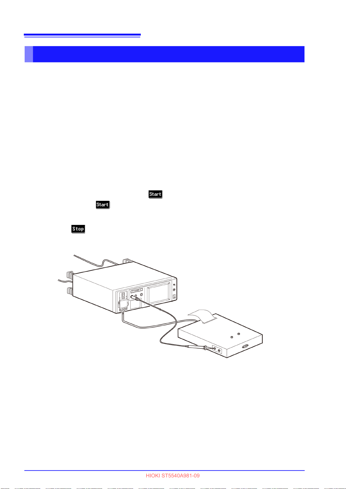
90
HIOKI ST5540A981-09
6.3 Measurement examples
Patient leakage current measurement* (Patient connection - Earth)
*
only when selecting a network B1 or B2 (B1 selected, patient leakage current I)
Measuring the class-I equipment and class-II equipment
1. Connect the instrument and the equipment under test.
See "3.3 Connecting equipment under test to the instrument" (p. 36)
2. Connect a test lead to terminal T2.
3. Position the tip of the test lead on the applied part of the equipment under test.
4. During manual measurement, patient leakage current (patient connection - earth)/patient leak-
age current I measurement starts upon return to the measurement screen.
Measurement conditions can be changed during measurement.
See "6.1 Making manual measurements" (p. 79)
During automatic measurements, becomes available upon return to the measurement
screen. Press to start patient leakage current (patient connection - earth)/patient leakage
current I measurement.
Only is available during automatic measurements.
2
4
1
3
Terminal T2 and applied part
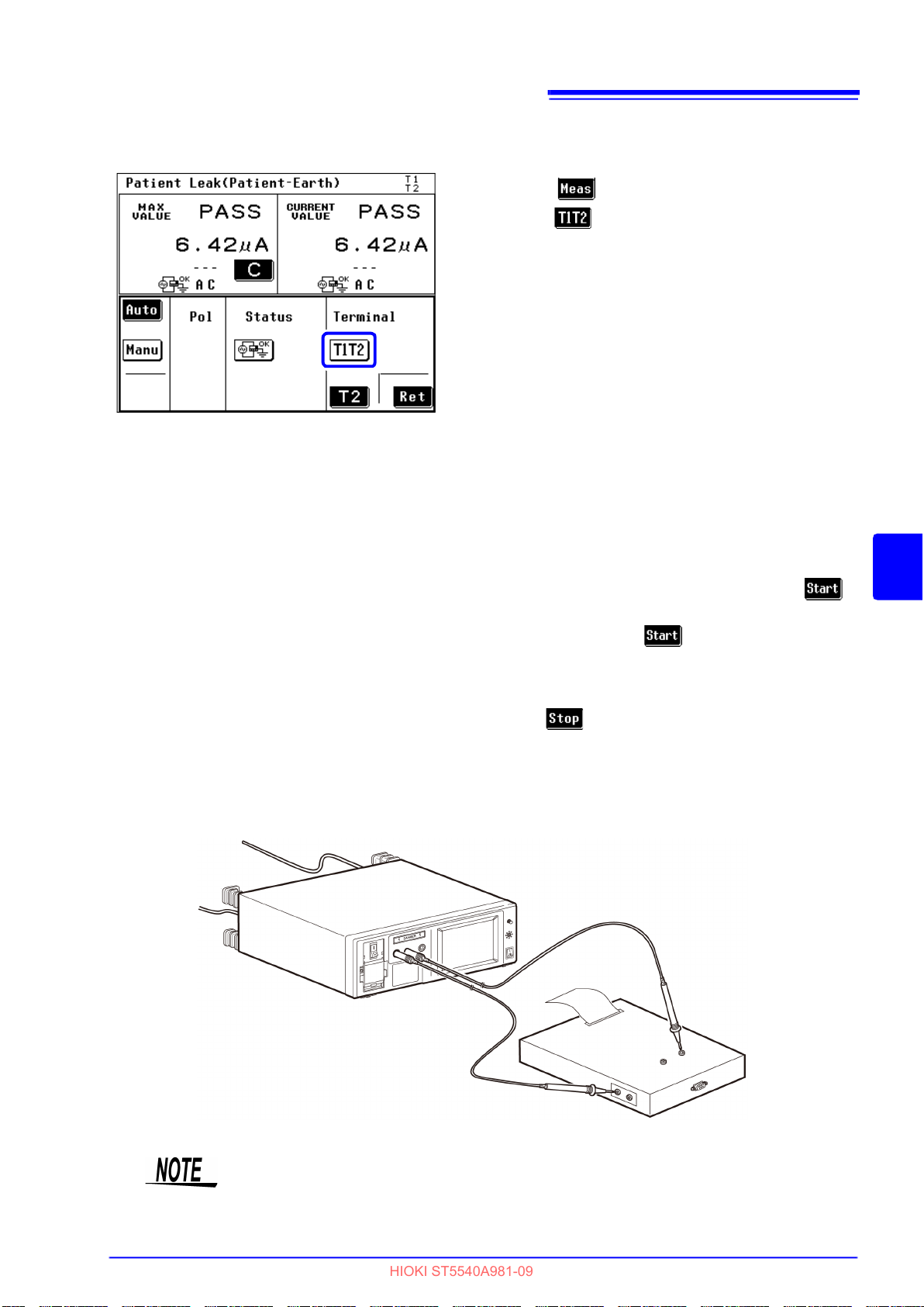
Measuring the internally powered equipment 1
HIOKI ST5540A981-09
1. Press in the measurement screen and
select under measured terminal.
2. Connect test leads to terminals T1 and T2.
3. Place the tip of test lead connected to the T1 ter-
minal on the enclosure of the equipment under
test.
1
4. Position the tip of the test lead connected to ter-
minal T2 on the applied part of the equipment
under test.
5. During manual measurement, patient leakage
current (patient connection - earth) measurement
starts upon return to the measurement screen.
Measurement conditions can be changed during
measurement.
See "6.1 Making manual measurements" (p. 79)
91
6.3 Measurement examples
2
During automatic measurements,
becomes available upon return to the measure-
ment screen. Press to start patient leakage
current (patient connection - earth) measurement.
Only is available during automatic measurements.
Terminal T1 and enclosure
1
6
Chapter 6 Measurements
4
Terminal T2 and applied part
When the instrument is set to internally powered equipment, even if the breaker
is turned On, the power supply to the equipment under test will be interrupted
(grounding connection will also be interrupted).
3

92
HIOKI ST5540A981-09
6.3 Measurement examples
Measuring the internally powered equipment 2
1. Press in the measurement screen and
select under measured terminal.
2. Connect test leads to terminals T2.
3. Position the tip of the test lead connected to termi-
nal T2 on the applied part of the equipment under
test.
4. During manual measurement, patient leakage cur-
1
rent (patient connection - earth) measurement
starts upon return to the measurement screen.
Measurement conditions can be changed during
measurement.
See "6.1 Making manual measurements" (p. 79)
2
During automatic measurements, becomes
available upon return to the measurement screen.
Press to start patient leakage current
(patient connection - earth) measurement.
Only is available during automatic measurements.
1
3
Terminal T2 and applied part
When the instrument is set to internally powered equipment, even if the breaker
is turned On, the power supply to the equipment under test will be interrupted
(grounding connection will also be interrupted).
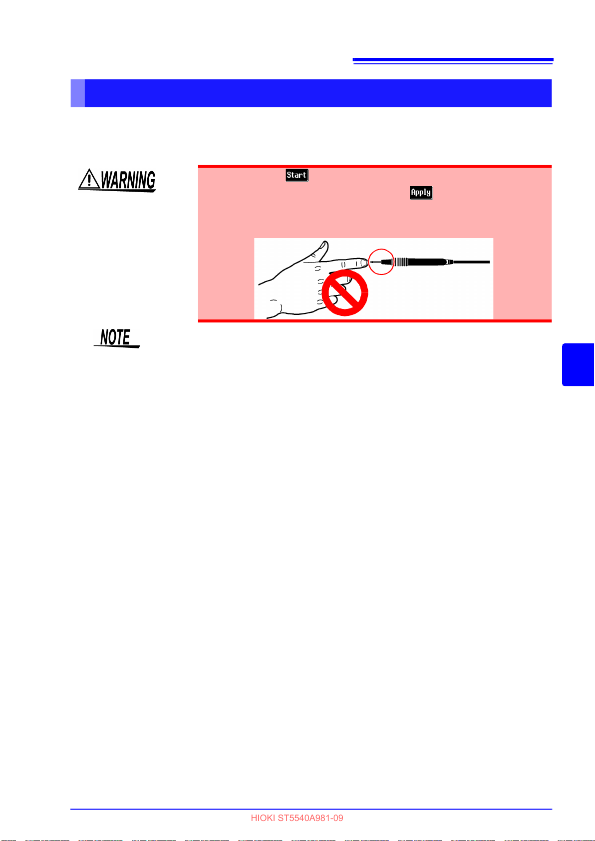
6.3 Measurement examples
HIOKI ST5540A981-09
Patient leakage current measurement* (external voltage on a SIP/SOP)
*
only when selecting network B1 or B2 and providing equipment with a Type B
applied part (B1 selected, patient leakage current II)
• Note that when is pressed in automatic measurement mode, the
instrument generates high voltage without displayed on the screen.
• To avoid the risk of electric shock when a test lead is connected to the T3
terminal, do not touch the part of the test lead that is beyond the finger
barrier. The T3 terminal outputs high voltages.
Do not touch any part of
the test lead beyond the
finger barrier
93
• If insulation of the signal input/output section and applied part is low due to
the output impedance (22.5 k ± 3 k) of the 110% voltage application function, a value at or below the allowable value may be detected. Take this into
consideration when setting the allowable value.
• The terminal block is not used for internally powered equipment. However,
power must be supplied to this instrument’s [LINE IN] connector to obtain high
voltage from Terminal T3. Do not connect the equipment under test to an outlet or the terminal block since power is supplied from an outlet during a 110%
voltage application test.
6
Chapter 6 Measurements

94
HIOKI ST5540A981-09
6.3 Measurement examples
1. Connect the instrument and the equipment under test.
See "3.3 Connecting equipment under test to the instrument" (p. 36)
2. Connect test leads to terminals T2 and T3.
3. Position the tip of the test lead connected to terminal T2 on the applied part of the equipment
under test.
4. Position the tip of the test lead connected to terminal T3 on an ungrounded signal input section
or signal output section of the equipment under test.
5. During manual measurement, is available upon return to the measurement screen. Press
to start patient leakage current (external voltage on a SIP/SOP)/patient leakage current II
measurement.
Pressing applies a high voltage to the test lead connected to the T3 terminal.
Press to terminate output of high voltage.
During automatic measurements, becomes available upon return to the measurement
screen. Press to start patient leakage current (external voltage on a SIP/SOP)/patient
leakage current II measurement.
Only is available during automatic measurements.
Terminal T3 and I/O terminal
2
red
5
1
black
3
Terminal T2 and applied part
4
 Loading...