

SP3000-01
NO
Instruction Manual
SP3000
NON-CONTACT AC VOLTAGE PROBE
SP9001
AC VOLTAGE PROBE
Feb. 2017 Edition 1
Printed in Japan
SP3000A961-00 17-02H
Warranty
Warranty malfunctions occurring under conditions of normal use in
conformity with the Instruction Manual and Product Precautionary
Markings will be repaired free of charge. This warranty is valid for
a period of one (1) year from the date of purchase. Please contact
the distributor from which you purchased the product for further
information on warranty provisions.
Introduction
Thank you for purchasing the Hioki SP3000-01, SP3000 NonContact AC Voltage Probe and SP9001 AC Voltage Probe. To obtain
maximum performance from the device, please read this manual
rst, and keep it handy for future reference.
Verifying Package Contents
When you receive the device, inspect it carefully to ensure that
no damage occurred during shipping. In particular, check the
accessories and connectors. If damage is evident, or if it fails to
operate according to the specications, contact your authorized
Hioki distributor or reseller.
Inspection Before Use
Verify that the device operates normally to ensure that no damage
occurred during storage or shipping. If you nd any damage, contact
your authorized Hioki distributor or reseller.
Precautions when transporting the device
During shipment of the device, handle it carefully so that it is not
damaged due to a vibration or shock.
Calibrations
The calibration period varies depending on the status of the device
or installation environment. We recommend that the calibration
period be determined in accordance with the status of the device
or installation environment. Please contact your Hioki distributor to
have your device periodically calibrated.
EN
Overview
The SP3000 Non-Contact AC Voltage Probe and the SP9001 AC
Voltage Probe are voltage probes that can make measurements
in a non-contact manner from outside cable insulation.
The SP3000 and SP9001 cannot be used alone. Instead, the two
units must be used together.
The model (order code) SP3001-01 Non-Contact AC Voltage
Probe indicates a package that includes both the SP3000 and
the SP9001.
Safety Information
This device is designed to conform to IEC 61010 Safety
Standards, and has been thoroughly tested for safety prior to
shipment. However, using the device in a way not described in
this manual may negate the provided safety features. Before
using the device, be certain to carefully read the following safety
notes:
DANGER
Mishandling during use could damage to the device.
Be certain that you understand the instructions and
precautions in the manual before use.
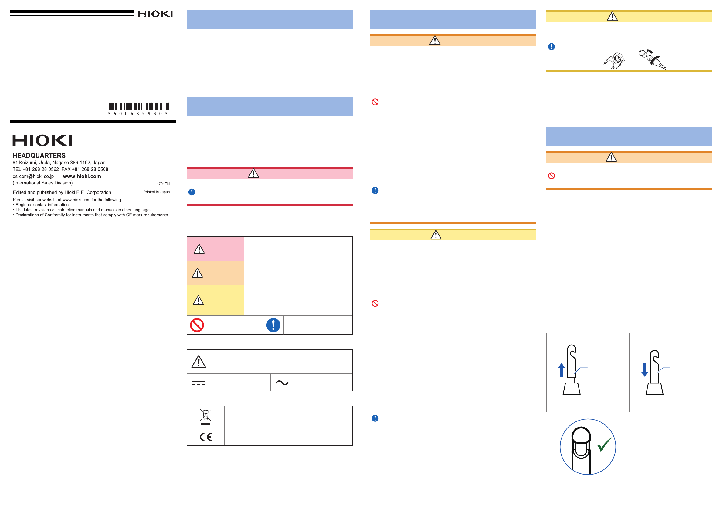
Notation
I
n this document, the risk seriousness and the hazard levels
are classied as follows
DANGER
WARNING
CAUTION
Indicates prohibited
actions.
Symbols on the device
Indicates cautions and hazards. When the symbol is
printed on the device, refer to a corresponding topic in
the Instruction Manual.
Indicates DC
(Direct Current)
Symbols for various standards
Indicates the Waste Electrical and Electronic
Equipment Directive (WEEE Directive) in EU
member states.
Indicates that the product conforms to regulations
set out by the EC Directive.
.
.
Indicates an imminently hazardous
situation that will result in death or serious
injury to the operator.
Indicates a potentially hazardous situation
that may result in death or serious injury to
the operator.
Indicates a potentially hazardous situation
that may result in minor or moderate injury
to the operator or damage to the device or
malfunction.
Indicates the action which
must be performed.
Indicates AC
(Alternating Current)
Operating Precautions
WARNING
•
Installing the device in inappropriate locations
may cause a malfunction of device or may give
rise to an accident. Avoid the following locations:
• Exposed to direct sunlight or high temperature
• Exposed to corrosive or combustible gases
• Exposed to a strong electromagnetic eld or
electrostatic charge
• Susceptible to vibration
• Exposed to water, oil, chemicals, or solvents
• Exposed to high humidity or condensation
• Exposed to high quantities of dust particles
• To avoid injury or damage to the device, do not
attempt to measure AC voltage, or DC voltage
exceeding 30 V
•
Use only the Model Z1013 AC Adapter. AC
adapter input voltage range is 100 V to 240 V
AC at 50 Hz/60 Hz. To avoid electrical hazards
and damage to the device, do not apply voltage
outside of this range.
• To avoid electrical accidents and to maintain the
safety specications of this device, connect the
power cord provided only to an outlet.
• Do not place foreign objects between the hookclip or
insert foreign objects into the gaps of the sensor head.
Doing so may worsen the performances of the sensor
or interfere with clamping action. Exercise caution due
to the potential for injury if a nger is pinched by the
hookclip.
• Be careful to avoid dropping the device or otherwise
subjecting them to mechanical shock, which could
damage the hookclip and adversely affect measurement.
• If you connect to metal BNC connector, the output
terminal (BNC connector) of the device may be
damaged.
• Do not use the probe in temperatures that exceed
the temperature at which the insulation on the cable
being measured softens. Doing so may result in cable
damage if the probe is connected to cable above that
temperature.
Before turning the device on, make sure the supply
•
voltage matches that indicated on its power connector.
Connection to an improper supply voltage may damage
the device and present an electrical hazard.
• Do not connect the supply voltage improperly. Doing so
may damage the device’s internal circuitry.
• This device is not drip-proof. Water droplets on the
device may result in malfunctions.
• To avoid damage to the device, protect it from physical
shock when transporting and handling. Be especially
careful to avoid physical shock from dropping.
• The cable of the device is hardened under the 0°C
or colder environment. Do not bend or pull it to avoid
tearing its shield or cutting cable
.
CAUTION
.
CAUTION
• To prevent damage to the BNC connector or junction, be
sure to unlock the connector and then pull it out while
gripping the BNC connector itself (rather than the cable)
• Displayed values can frequently uctuate due to induction
potential even when no voltage is applied. This, however, is not
a malfunction.
• Unplugging the USB cable kills power to the device. Be sure to
provide enough unobstructed space to unplug the USB cable
immediately in an emergency.
.
Maintenance and Service
WARNING
Customers are not allowed to modify, disassemble,
or repair the device. Doing so may cause re,
electric shock, or injury
• To prevent damage to terminals from repeatedly connecting
and disconnecting them, leave the USB cable, AC voltage
probe, and GND connection cable connected when storing the
device in a container such as its carrying case.
• To clean the device, wipe it gently with a soft cloth moistened
with water or mild detergent.
• Use a soft, dry cloth to lightly wipe away any dirt or other
material on the metal portion of the hookclip as it may affect
measurement.
• If the device seems to be malfunctioning, conrm that the AC
adapter, the UCB cable, the AC voltage probe and the GND
connection cable are connected properly before contacting
your authorized Hioki distributor or reseller.
Replacing the protective sleeve of hookclip
Protective sleeve of the SP9001 AC Voltage Probe can be
replaced. Replacement sleeves can be purchased via authorized
Hioki distributor or reseller.
Remove Attach
Protective
sleeve
Grip the protective sleeve at its
base and pull up to remove.
OK
.
Protective
sleeve
Push the protective sleeve down
securely all the way to attach.
Exercise care not to tear the
protective sleeve on the opening
of the hookclip when attaching it.
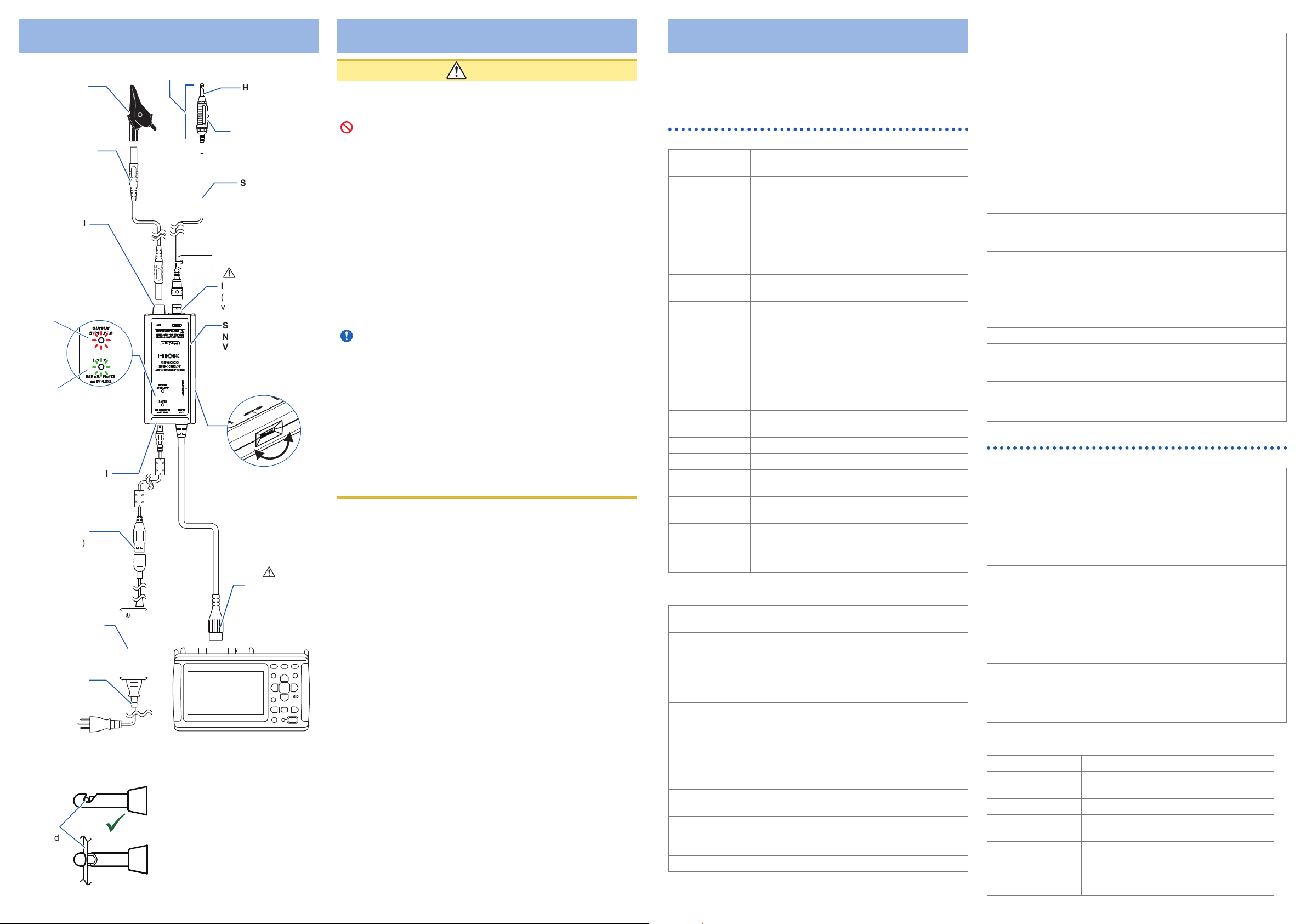
Parts Names, Connection Example
NO
4
Alligator clip
GND connection
cable (1.5 m)
,
5
Probe's tip
6
Hookclip
Open and close
lever
SP9001
AC Voltage Probe
3
GND terminal
OUTPUT OVERLOAD
Lights up or blinks when
the device’s output voltage
waveform might be saturated.
POWER
Lights up when power is being
supplied.
11
1
,
USB power terminal
(USB-mini B)
USB cable
(1.5 m)
Input terminal
(For use with AC
voltage probe only)
SP3000
Non-Contact AC
Voltage Probe:
amplier box
7
Dial for zero
adjustment (0 ADJ)
2
Output terminal
(BNC connector)
Z1013 AC Adapter
Power cord
To commercial power
Connected device (example
How to properly connect the probe to the cable being
measured
• If the cable being measured is
dirty, wipe away the dirt before
Cable
being
measured
OK
connecting the probe.
• Insert the cable all the way into
the tip of the probe.
• Proper measurement is not
possible if the cable is inserted
partway or at an angle.
Accuracy specications
Measurement Procedure
CAUTION
• Do not connect the device’s output terminal (BNC
connector) to an instrument with an input resistance of
or less. Doing so may damage the device. The
10 k
Ω
device’s signal output circuit includes an output resistor.
When monitoring the device’s output signal with a digital
multimeter or similar instrument, use an instrument with
a high input resistance (recommended input resistance:
or greater).
1 M
Ω
• GND terminal of the SP3000, USB power terminal GND
pin, and output terminal (BNC connector) GND pin are
not insulated (i.e., they share a common ground). In
the event there were a potential difference between
any of these ground signals, a current could ow
through the ground circuit of the SP3000, damaging the
measurement object and device.
• Although the measurement waveform’s zero point
may exhibit wobble at low frequencies, this is a normal
characteristic of the device and does not indicate a
problem. When using a Memory HiCorder, oscilloscope,
or other waveform measuring instrument, this wobbling
characteristic can be improved by selecting the
instrument’s AC coupling setting. (The AC coupling
characteristics will affect the waveform, so be sure that
you have a thorough understanding of AC coupling
before using this feature.)
• Do not connect the probe to a bare conductor with
exposed metal or a measurement cable with damaged
insulation. Doing so may damage the device as well as
the connected instrument.
• Be sure to wipe the cable to remove any dirt before
connecting the probe and ensure that no dirt gets
onto the probe. In particular, any dirt that gets onto the
hookclip may adversely affect the sensor characteristics
or damage the device.
• The probe is affected by nearby conductors (cables).
Exercise care as this effect becomes more pronounced
the closer a conductor is to the opening in the hookclip.
Supply power to the device.
1
This can be accomplished by either of the following two
methods:
• Use the Z1013 AC Adapter to supply power from commercial
power.
• Connect the device to a USB receptacle that has USB bus
power functionality.
Connect the output terminal (BNC connector) to the
2
input terminal on the instrument to which you wish
to connect the device.
Connect the GND connection cable to the GND
3
terminal.
Connect the alligator clip to the GND connection
4
cable.
Connect the alligator clip to the measurement
5
object’s GND contact.
Connect the voltage probe (the SP9001) to one (and
6
only one) cable.
Execute zero adjustment.
)
7
Rotate the zero adjustment dial (labeled “0 ADJ”) on the right
side of the device to set the zero point for the waveform.
Start the measurement.
8
After measurement is complete, disconnect
9
the alligator clip and voltage probe from the
measurement object. (See the lower left gure.)
Disconnect the device from the instrument.
10
Disconnect the USB cable that is supplying power
11
to the device from the AC adapter or the host
device’s USB receptacle.
Specifications
f.s. : The rated measurement voltage.
rdg.: The value currently being measured and indicated on the
measuring instrument.
SP3000 Non-Contact AC Voltage Probe
General Specications
Operating
environment
Operating
temperature and
humidity
Storage
temperature and
humidity
Standards Safety: EN 61010
Power supply USB bus power USB-mini B terminal
Maximum rated
power
Dimensions Approx. 120W × 25H × 55D mm (4.72″W × 0.98″H
Mass Approx. 160 g (5.6 oz.) (including the cable)
Cable length Approx. 1.5 m
Product warranty
period
Accessories GND connection cable (1.5 m), Alligator clip,
Options SP9001 AC Voltage Probe
Input / Output / Measurement Specications
Basic specications
Probe signal input
terminal
GND input
terminal
Output terminal Insulated BNC terminal
Rated measured
voltage
Maximum imput
voltage
Output rate 1 V/V
Rising time
(10% to 90%)
Frequency range 10 Hz to 100 kHz (−3 dB band)
Measurement
method
OUTPUT
OVERLOAD
detection
Output resistance 50
Indoor use, pollution degree 2,
altitude up to 2000 m (6562 ft.)
Temperature: −10°C to 50°C (14°F to 122°F)
Humidity: −10°C to 40°C (14°F to 104°F),
80% RH or less (no condensation)
40°C to 50°C (104°F to 122°F), 60% RH or less
(no condensation)
−20°C to 60°C (−4°F to 140°F), 80% RH or less
(no condensation)
EMC: EN 61326
5 V ±0.25 V DC
Z1013 AC Adapter: (5 V DC, 2.6 A)
Rated supply voltage: 100 V to 240 V AC
Rated supply frequency: 50 Hz/60 Hz
Anticipated transient overvoltage: 2500 V
When using USB bus power: 1.5 VA
When using Z1013 AC Adapter: 7.5 VA (including
AC Adapter)
× 2.17″D) (excluding protrusions)
1 year
USB cable (1.5 m), Instruction manual
Z1013 AC Adapter
C1011 Carrying Case
9804-02 Magnet Adapter
BNC terminal
Banana input terminal
5 V rms (14.14 V p-p)
RMS: 30 V rms or less
Peak value: 42.4 V peak or less
4.5 µs or less
Coupling capacitance cancelation method
(cannot be used with bare conductors)
Detected when the peak value including offset
exceeds the next voltage value
±7 V±0.5 V
±5%
Ω
Conditions of
guaranteed
accuracy
Voltage
measurement
accuracy
Effect of measured
wire
Temperature
coefcient
Output noise 100 mV rms (as a referential)
Effect of radiated
radio-frequency
electromagnetic eld
Effect of conducted
radio-frequency
electromagnetic eld
Guaranteed accuracy period: 1 year
Guaranteed accuracy period from adjustment
made by Hioki: 1 year
Temperature and humidity for guaranteed
accuracy: 23°C±5°C (73°F±9°F), 80% RH or
less
Using SP9001 and Z1013 in combination
Using wire with PVC insulation, a standard
nished outer diameter of φ1.75 mm ±0.15 mm,
and a standard insulator thickness of 0.40 mm
±0.05 mm
After zero adjustment, not including various
effects
50 Hz/60Hz sinusoidal input
With a measuring instrument with an input
resistance of at least 1 M
±2.5% rdg.±1 % f.s. (0.5 V rms to 5 V rms)
±5% rdg. (using UL1007-/UL1015-/AV-/AVS-/
AVSS-compliant wire with a nished outer
diameter of φ1.0 to 2.5 mm)
In the operating temperature range, add
0.1% rdg./°C (at temperatures other than
23°C±5°C)
±5% f.s. at 10 V/m
±5% f.s. at 10 V
Ω
SP9001 AC Voltage Probe
General Specications
Operating
environment
Operating
temperature and
humidity
Storage
temperature and
humidity
Standards Safety: EN 61010
Dimensions Approx. 15.0W × 13.9H × 77.4D mm (0.59″W ×
Mass Approx. 52g (1.8 oz.) (including the cable)
Cable length Approx.1.0 m
Product warranty
period
Accessory Instruction manual
Input / Output / Measurement Specications
Basic specications
Output terminal BNC terminal with protective sleeve
Maximum imput
voltage
Measurable wire Insulated wire
Measurable wire
outer diameter
Measurement
method
Opening and closing
of the probe
Indoor use, pollution degree 2,
altitude up to 2000 m (6562 ft.)
Temperature: −10°C to 50°C (14°F to 122°F)
(Probe’s tip: −10°C to 80°C (14°F to 176°F)
Humidity: −10°C to 40°C (14°F to 104°F),
80% RH or less (no condensation)
40°C to 80°C (104°F to 176°F), 60% RH or less
(no condensation)
−20°C to 60°C (−4°F to 140°F), 80% RH or less
(no condensation)
0.55″H × 3.05″D) (excluding protrusions)
1 year
RMS: 30 V rms or less
Peak value: 42.4 V peak or less
1.0 mm to φ2.5 mm
φ
Coupling capacitance cancelation method
(cannot be used with bare conductors)
10,000 times
 Loading...