

SM7860
SM7860-51
SM7860-52
SM7860-53
SM7860-54
SM7860-55
SM7860-56
SM7860-57
SM7860-58
SM7860-61
SM7860-62
SM7860-63
SM7860-64
SM7860-65
SM7860-66
SM7860-67
SM7860-68
Instruction Manual
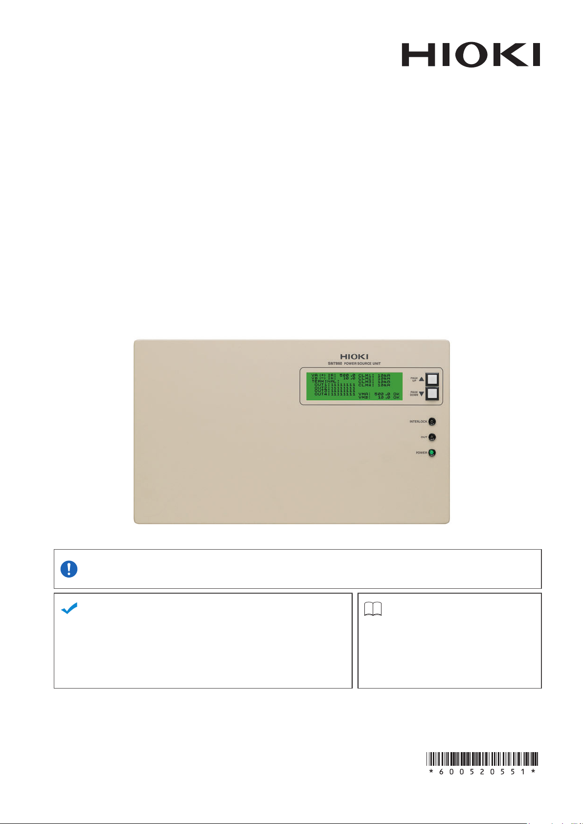
POWER SOURCE UNIT
Be sure to read this manual
before using the device
When using the device for the rst time Troubleshooting
Part Names and Functions
Screen Conguration
Installation and Connection Procedures
July 2018 Revised edition 1
SM7860J961-01 18-07H
p.
p.
p.
10
13
15
Safety Information
Troubleshooting
Error Display
p.
p.
p.
4
53
55
EN


Contents
Introduction
Notation
Verifying Package Contents
Safety Information
Operating Precautions
........................................................1
..............................................................2
............................3
............................................4
.....................................4
1 Overview 9
1.1 Product Overview and Features
1.2 Part Names and Functions
1.3 ScreenConguration
...........................13
...........9
.................10
2 Preparation and Supply
Power
2.1 Installation and Connection
Procedures
2.2 Connecting the Power Cord
2.3 Connecting the Device to the
Measuring Instrument
2.4 Inspection Before Operation
2.5 Turn ON/OFF the power
2.6 Operating Conditions Setting
2.7 Output Setting for the Device
Interlocked
15
............................................15
................16
..........................17
...............18
......................19
..............20
.............................................21
4 External Control 37
4.1 EXT I/O Connector and Signals
Connector Type and Signal Pinouts
Signal Functions
4.2 Timing Chart
4.3 Internal Circuitry
.......................................39
..........................................40
....................................44
.........37
...........38
5 Specications 45
5.1 GeneralSpecications
5.2 BasicSpecications
Graph description and operating
precautions
...............................................50
5.3 Input / Output Functions
.........................45
.............................46
......................52
6 Maintenance and Service 53
6.1 Troubleshooting
6.2 Error Display
6.3 Repairs, Inspections, and Cleaning
6.4 Replacing the Power Fuse
Warranty Certicate
....................................53
.........................................55
...55
..................56
3 Changing the Interface 23
3.1 Overview and Features of the
Interfaces
3.2 InterfaceSpecications
3.3 Connecting the Interface
Using the GP-IB Interface
Using the RS-232C Interface
3.4 ConguringtheCommunications
Protocol
ConguringGP-IBInterface
Communications
ConguringRS-232CInterface
Communications
3.5 Communication Method
Status Byte Register
Event Register
Error Register
3.6 Message List
3.7 ListenerSpecicationPrecautions
Input buffer size
Reading from the output buffer
...............................................23
.......................24
.....................26
GP-IB
..................................................27
GP-IB
...........................27
RS-232C
.................................30
..........................................31
...........................................33
.........................................34
........................................36
..............26
RS-232C
.......................28
.......................28
..................36
.....26
.....36
SM7860J961-01
i

Contents
ii
Introduction
Introduction
Thank you for purchasing the Hioki Model SM7860 series Power Source Unit.
To obtain maximum performance from the device over the long term, be sure to read this manual carefully
and keep it handy for future reference.
Target audience
This manual has been written for use by individuals who use the product in question or who teach
others to do so. It is assumed that the reader possesses basic electrical knowledge (equivalent to that of
someone who graduated from the electrical program at a technical high school).
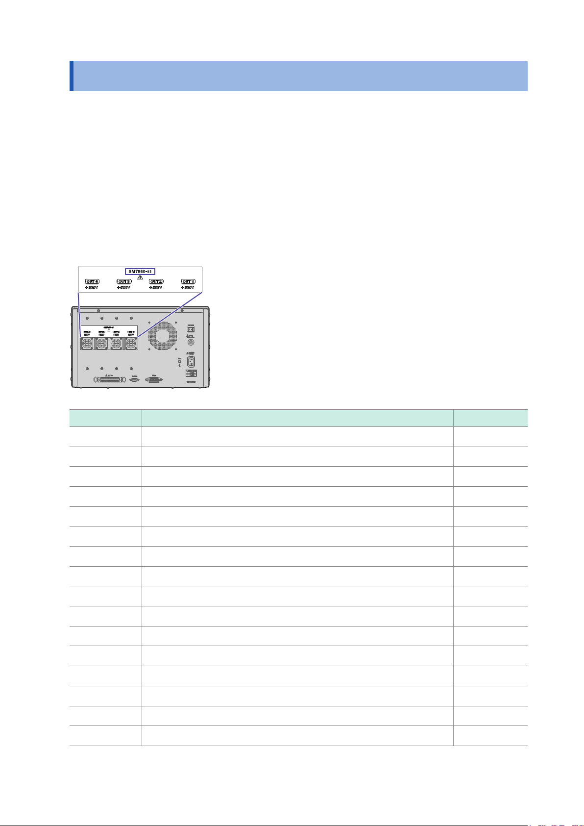
Finding the product’s model number
You can nd the model number on the rear of the device.
Model Overview Supply voltage
SM7860-51 500 V × 32 channels 100 V to 110 V
SM7860-52 1000 V × 32 channels 100 V to 110 V
SM7860-53 500 V × 16 channels, −500 V × 16 channels 100 V to 110 V
SM7860-54 1000 V × 16 channels, −1000 V × 16 channels 100 V to 110 V
SM7860-55 500 V × 8 channels, −500 V × 8 channels, discharge × 16 channels 100 V to 110 V
SM7860-56 1000 V × 16 channels, −1000 V × 16 channels, discharge × 16 channels 100 V to 110 V
SM7860-57 10 V × 24 channels, discharge × 8 channels 100 V to 110 V
SM7860-58 500 V × 24 channels, discharge × 8 channels 100 V to 110 V
SM7860-61 500 V × 32 channels 220 V
SM7860-62 1000 V × 32 channels 220 V
SM7860-63 500 V × 16 channels, −500 V × 16 channels 220 V
SM7860-64 1000 V × 16 channels, −1000 V × 16 channels 220 V
SM7860-65 500 V × 8 channels, −500 V × 8 channels, discharge × 16 channels 220 V
SM7860-66 1000 V × 16 channels, −1000 V × 16 channels, discharge × 16 channels 220 V
SM7860-67 10 V × 24 channels, discharge × 8 channels 220 V
SM7860-68 500 V × 24 channels, discharge × 8 channels 220 V
1
Notation
Notation
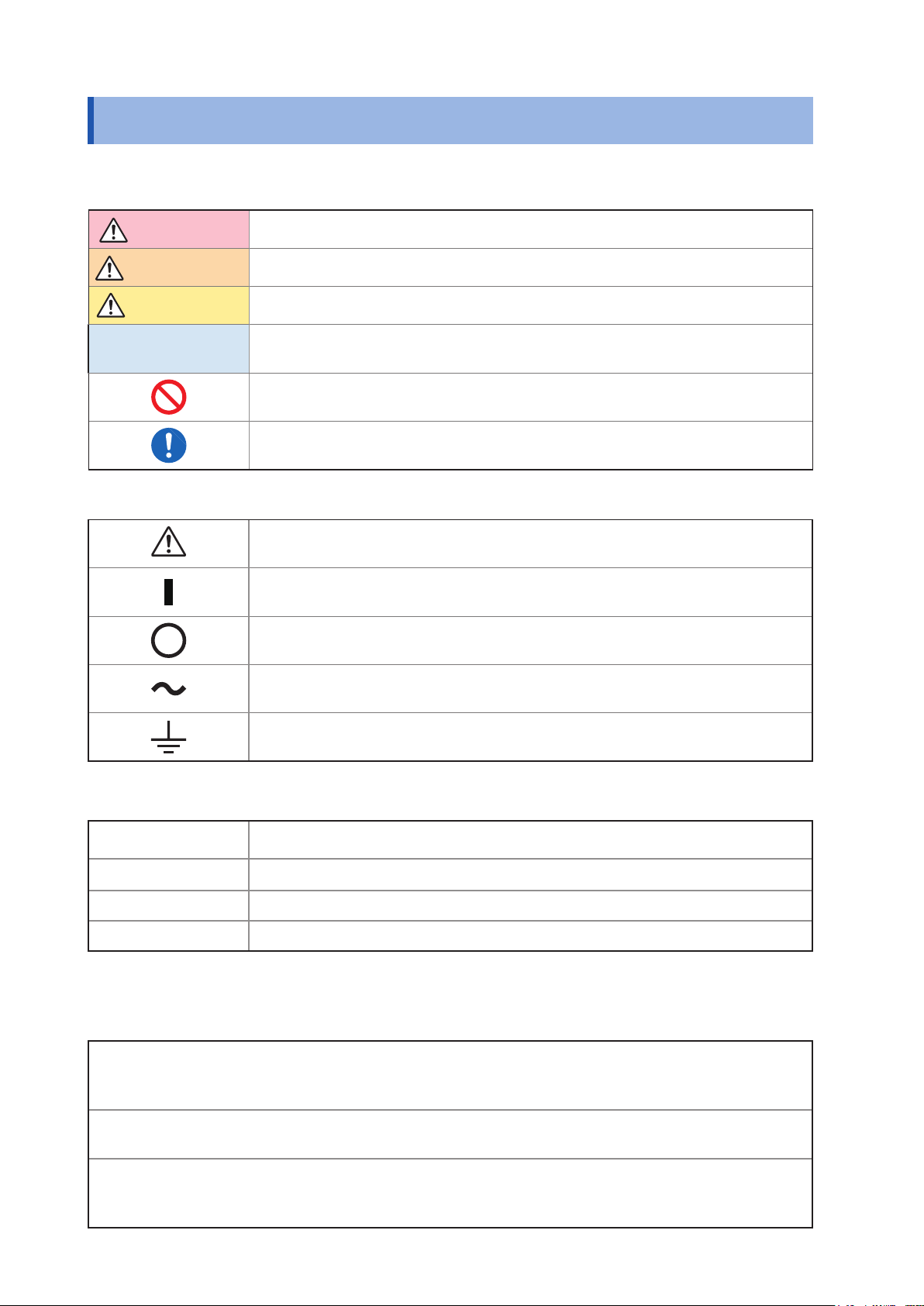
Concerning Safety
In this document, the risk seriousness and the hazard levels are classied as follows.
DANGER
WARNING
CAUTION
IMPORTANT
Imminent risk of operator death or serious injury
Potential for operator death or serious injury
Potential for minor operator injury or device damage or malfunction
Indicates information related to the operation of the device or maintenance tasks
with which the operators must be fully familiar.
Prohibited actions
Actions that must be performed
Symbols Afxed to the Device
Precaution or hazard (See “Operating Precautions”.)
ON side of the power switch
OFF side of the power switch
AC (alternating current)
Grounding terminal
Others
*
p.
[ ]
ON
Additional information is presented below.
Indicates the location of reference information.
Key names are indicated in brackets.
Names and keys on the screen are shown in boldface.
Accuracy
We dene measurement tolerances in terms of f.s. (full scale), rdg. (reading), and dgt. (digit) values, with
the following meanings:
f.s. (maximum display value)
f.s.
rdg.
The maximum displayable value. This is usually the name of the currently
selected range.
rdg. (reading or displayed value)
The value currently being measured and indicated on the measuring device.
dgt. (resolution)
dgt.
The smallest displayable unit on a digital measuring device, i.e., the input value
that causes the digital display to show a “1” as the least-signicant digit.
2
Verifying Package Contents
Verifying Package Contents
When you receive the device, inspect it carefully to ensure that no damage occurred during shipping.
In particular, check the accessories, panel switches, and connectors. If damage is evident, or if it fails to
operate according to the specications, contact your authorized Hioki distributor or reseller.
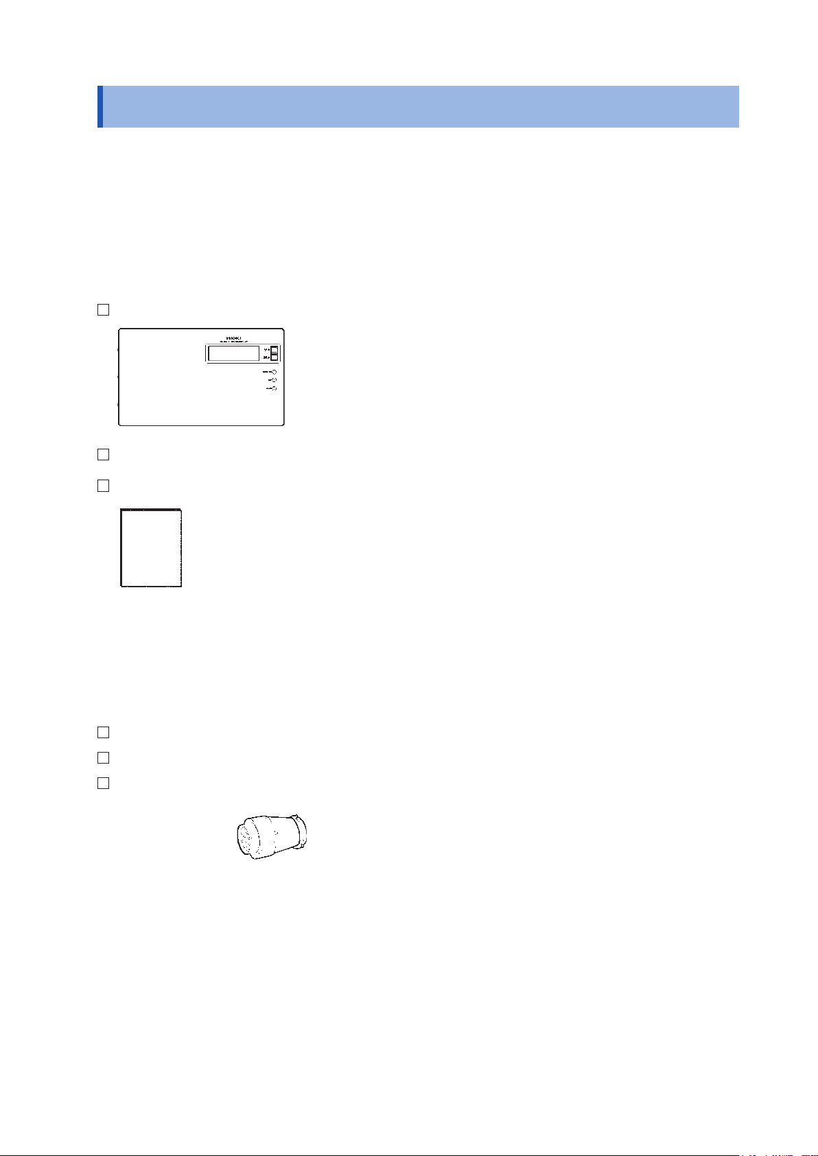
Device and Accessories
Conrm that you have received the following items:
Model SM7860 series Power Source Unit
Power cord
Instruction Manual (This document)
Options
The following options are available for the device. Contact your authorized Hioki distributor or reseller
when ordering.
Model 9637 RS-232C Cable (9pin-9pin/1.8 m) Cross
Model 9151-02 GP-IB Connector Cable 2 m
Model L2221 Connector Voltage output
3
Safety Information
Safety Information
Before using the device, be certain to carefully read the following safety notes.
DANGER
Mishandling during use could result in injury or death, as well as damage to the
device. Be certain that you understand the instructions and precautions in the
manual before use.
WARNING
• With regard to the electricity supply, there are risks of an electric shock,
heat generation, re, and arc ash due to a short-circuit. Individuals using
an electrical measuring device for the rst time should be supervised by a
technician who has experience in electrical measurement.
• Protective gear
This device is measured on a live line. To prevent an electric shock, use
appropriate protective insulation and adhere to applicable laws and regulations.
Operating Precautions
Follow these precautions to ensure safe operation and to obtain the full benets of the various functions.
Checks before use
DANGER
If the connection cord or the device is damaged, there is a risk of an electric
shock. Perform the following inspection before using the device:
• Check that the coatings of the connection cords are neither ripped nor torn and
that no metal parts are exposed. Using the device under such conditions could
result in an electric shock. Replace the connection cords with those specied
by our company.
• Verify that the device operates normally to ensure that no damage occurred
during storage or shipping. If you nd any damage, contact your authorized
Hioki distributor or reseller.
WARNING
To prevent an electric shock, conrm that the white or red portion (insulation
layer) inside the cable is not exposed. If a color inside the cable is exposed, do
not use the cable.
4
Installing the device
• Ventilation holes for heat radiation are provided on the side and rear panels of
the device. Leave sufcient space around the ventilation holes and install the
device with the holes unobstructed. Installation of the device with the ventilation
holes obstructed may cause a malfunction or a re.
• Unplugging the power cord kills power to the device. Be sure to provide enough
unobstructed space to unplug the power cord immediately in an emergency.
Installing the device in inappropriate locations may cause a malfunction of device
or may give rise to an accident. Avoid the following locations:
• Exposed to direct sunlight or high temperature
• Exposed to corrosive or combustible gases
• Exposed to a strong electromagnetic eld or electrostatic charge
• Near induction heating systems (such as high-frequency induction heating
systems and IH cooking equipment)
• Susceptible to vibration
• Exposed to water, oil, chemicals, or solvents
• Exposed to high humidity or condensation
• Exposed to high quantities of dust particles
Operating Precautions
WARNING
CAUTION
Failure to observe the following precaution may result in bodily injury.
• The device weighs approx. 47 kg (Model SM7860-57 and SM7860-67: approx. 34 kg).
It should be moved by at least two people, who should grip it using the handles on the
left and right sides. The center of gravity is located on the front side of the device.
• The device is heavy. When transporting it, follow your company’s workplace safety
standards to assure safety (for example, by wearing non-slip gloves and protective
footwear).
Do not place the device on an unstable table or inclined place. Dropping or knocking
down the device can cause injury or damage to the device.
5
Operating Precautions
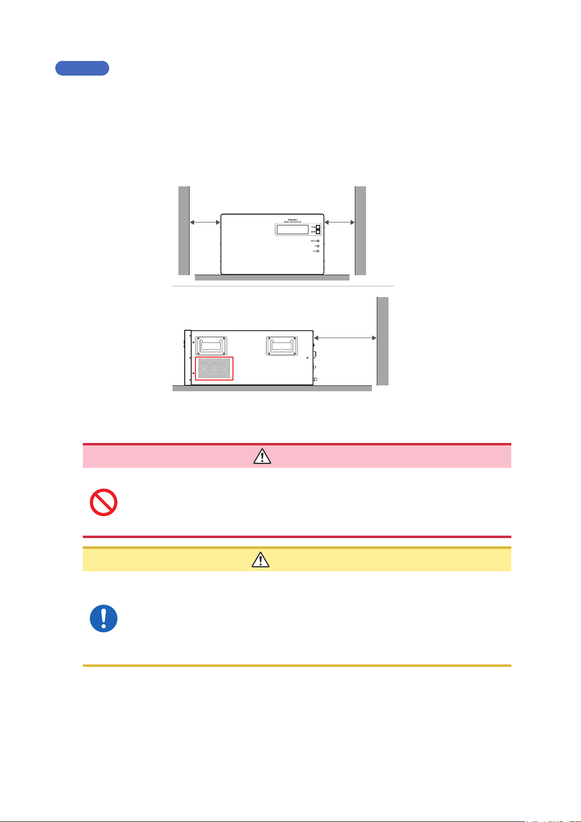
Installing
Prolonged operation in hot temperatures will shorten the device’s service life. Keep the ambient temperature
as low as possible.
• Avoid obstructing the ventilation holes.
• To prevent overheating, be sure to leave the specied clearances around the device.
• When rack-mounting the device, fans must be installed above or on top of the rack to ensure proper
ventilation. Be sure that the rack is adequately ventilated so that the internal temperature remains at or
below 40°C.
Handling the Device
• Do not use the device with circuits that exceed its ratings or specications.
Doing so may damage the device or cause it to become hot, resulting in a bodily
injury.
• Do not short-circuit two wires to be measured by bringing the cable into contact
with them. Arcs or such grave accidents are likely to occur.
50 mm or more
Prevent from
blocking
50 mm or more
100 mm or more
DANGER
CAUTION
Failure to observe the following precaution may result in bodily injury.
• The device weighs approx. 47 kg (Model SM7860-57 and SM7860-67: approx. 34 kg).
It should be moved by at least two people, who should grip it using the handles on the
left and right sides. The center of gravity is located on the front side of the device.
• The device is heavy. When transporting it, follow your company’s workplace safety
standards to assure safety (for example, by wearing non-slip gloves and protective
footwear).
6
Handling the Cords
If the insulation on a cord melts, the metal conductor may be exposed. Do not use
any cord whose metal conductor is exposed. Doing so could result in an electric
shock, burn, or other hazards.
To avoid damaging the power cord, grasp the plug, not the cord, when unplugging it
from the outlet or device.
To prevent cord damage, do not step on cords or pinch them between other objects. Do
not bend or pull on cables at their base.
IMPORTANT
Use only the specied connection cords. Use of any cable not specied by our company may
result in incorrect measurements due to poor connection or other reasons.
Operating Precautions
WARNING
CAUTION
To ensure accurate measurements
• Warm up the device an hour or more before use.
• The device should be calibrated once a year.
Transporting Precautions
• To ensure safe handling, when transporting the device, please use the original box and packing
materials, but do not use if the box is damaged or warped, or if the packing materials are in poor
condition or incomplete.
• When packing the device, make sure to disconnect power supply cords from the main device.
• When transporting, avoid dropping or other excessive impacts.
7

Operating Precautions
8

1
Overview
1.1 Product Overview and Features
The SM7860 series Power Source Unit is a power source designed for use with the SM7420 Super
Megohm Meter and SM7810‑20 Super MΩ HiTester. When used in conjunction with the SM7420 or
SM7810‑20, the SM7860 serves as an ideal power source for automatic testing and measurement of
capacitors.
Positive- and negative-polarity output / Multi-channel output
• The device supports multichannel systems with up to 32 channels.
• The output voltage can be set separately for two circuits, each consisting of 8 or 16 channels.
• The device provides both positive‑ and negative‑polarity power sources.
• It can be used to create an optimal testing line with the minimum necessary number of power sources.
Independent on/off output switching and current limitations for all channels
• Since each channel has its own output on/off switch, it is possible to control voltage application
without an external circuit (allowing charging and discharging).
• Use of semiconductor switches eliminates the need for maintenance.
• Ability to limit current for individual channels means the measurement of other channels won’t be
affected when a target workpiece has a short.
Variable output current limit value
• 500 V output model: The output current limit can be set as desired from 2 mA per channel to 50 mA
per channel.
• 1000 V output model: The output current limit can be set as desired from 2 mA per channel to 10 mA
per channel.
1000 V output voltage model
• The line includes a model that can generate output of up to ±1000 V.
High-current output at 50 mA/channel*
• The device can quickly charge high‑capacity MLCC (multi‑layer ceramic capacitor). Number of
charges can be reduced.
* For the 1000 V model, limited to 10 mA/channel.
Standard interfaces
• Devices ship standard with EXT. I/O, GP‑IB, and RS‑232C interfaces for sequencing. Interfaces are
used to congure and power the device.
Interlock function
• Since the device outputs measurement and charging voltages when measurement starts, erroneous
operation poses the risk of electric shock. An interlock function is used to ensure safe measurement.
Settings can be congured by sending signals via the device’s external I/O interface.
9
Part Names and Functions
1 2
3
4
5
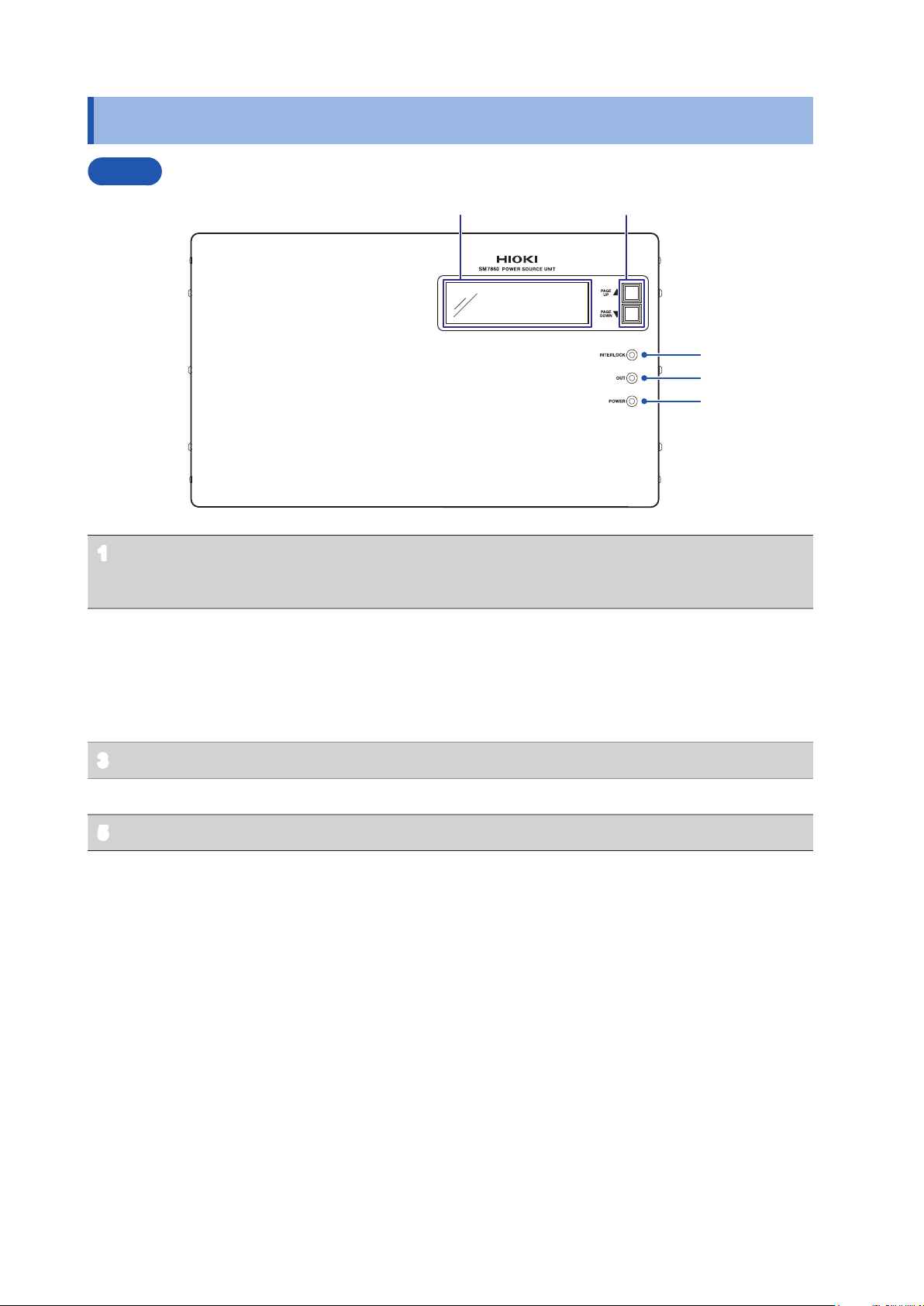
1.2 Part Names and Functions
Front
Display (LCD) The screen uses a 2‑page layout to display setting values
1
and setting status information.
Refer to “1.3 Screen Conguration” (p. 13)
Scroll keys
2
[PAGE UP▲], [PAGE DOWN▼]
Interlock indicator (INTERLOCK) Lights up when the interlock is on.
3
Voltage output indicator (OUT) Lights up when a voltage is being output.
4
Power indicator (POWER) Lights up when the device is on.
5
• Use to scroll the display (LCD).
Refer to “1.3 Screen Conguration” (p. 13)
• Used to assign the GP-IP address and to congure the
output setting for the device interlocked.
Refer to “Conguring GP-IB Interface Communications
GP-IB” (p. 27)
10
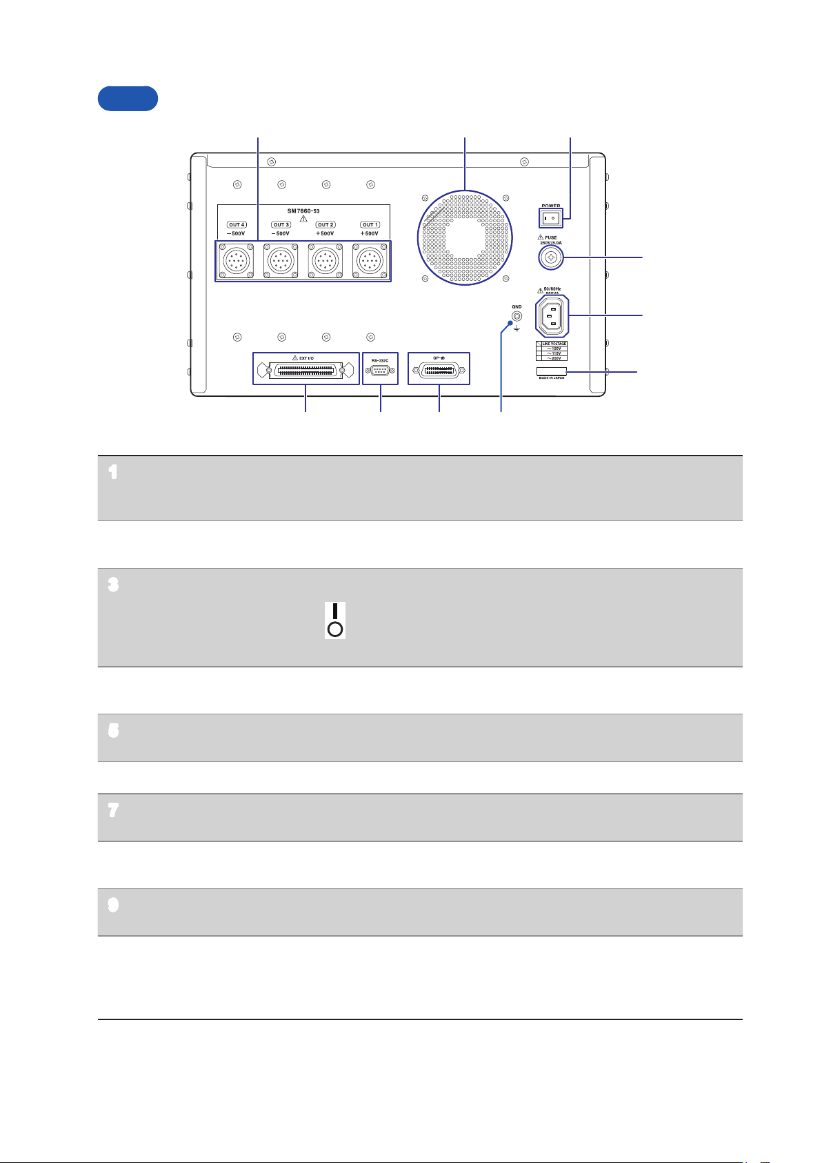
Rear
1 32
4
5
6 789
10
Part Names and Functions
Voltage output terminal Voltage is output. Connect the optional Model L2221 Connector.
1
Ventilation holes Keep clear of obstructions.
2
Power switch (POWER) Turns the device on and off.
3
Fuse holder (FUSE) Fuse can be replaced.
4
Power inlet Connect the supplied power cord.
5
GND terminal Serves as the ground terminal. Connects to the device’s enclosure.
6
GP‑IB connector Connect to a PC when using the GP‑IB interface.
7
RS‑232C connector Connect to a PC when using the RS‑232C interface.
8
Refer to “2.3 Connecting the Device to the Measuring Instrument”
(p. 17)
Refer to “Installing” (p. 6)
: Power ON
: Power OFF
Refer to “2.5 Turn ON/OFF the power” (p. 19)
Refer to “6.4 Replacing the Power Fuse” (p. 56)
Refer to “2.2 Connecting the Power Cord” (p. 16)
Refer to “Using the GP-IB Interface GP-IB” (p. 26)
Refer to “Using the RS-232C Interface RS-232C” (p. 26)
EXT I/O connector The EXT I/O connector can be used to control the device.
9
Refer to “4 External Control” (p. 37)
Serial number The serial number consists of 9 digits. The rst two (from the left)
10
indicate the year of manufacture, and the next two indicate the
month of manufacture.
Required for production control. Do not peel off the label.
11
Part Names and Functions
1
2
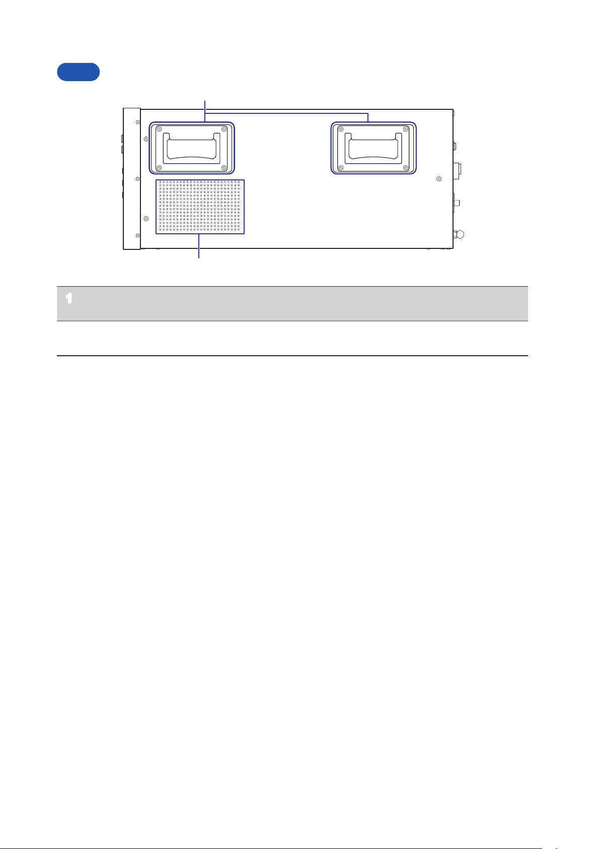
Side
Handle (total of 4, located on the
1
left and right sides of the device)
Ventilation holes Keep clear of obstructions.
2
It should be moved by at least two people, who should grip
it using the handles on the left and right sides.
Refer to “Installing” (p. 6)
12
Screen Conguration
1
3 4 5 6
27
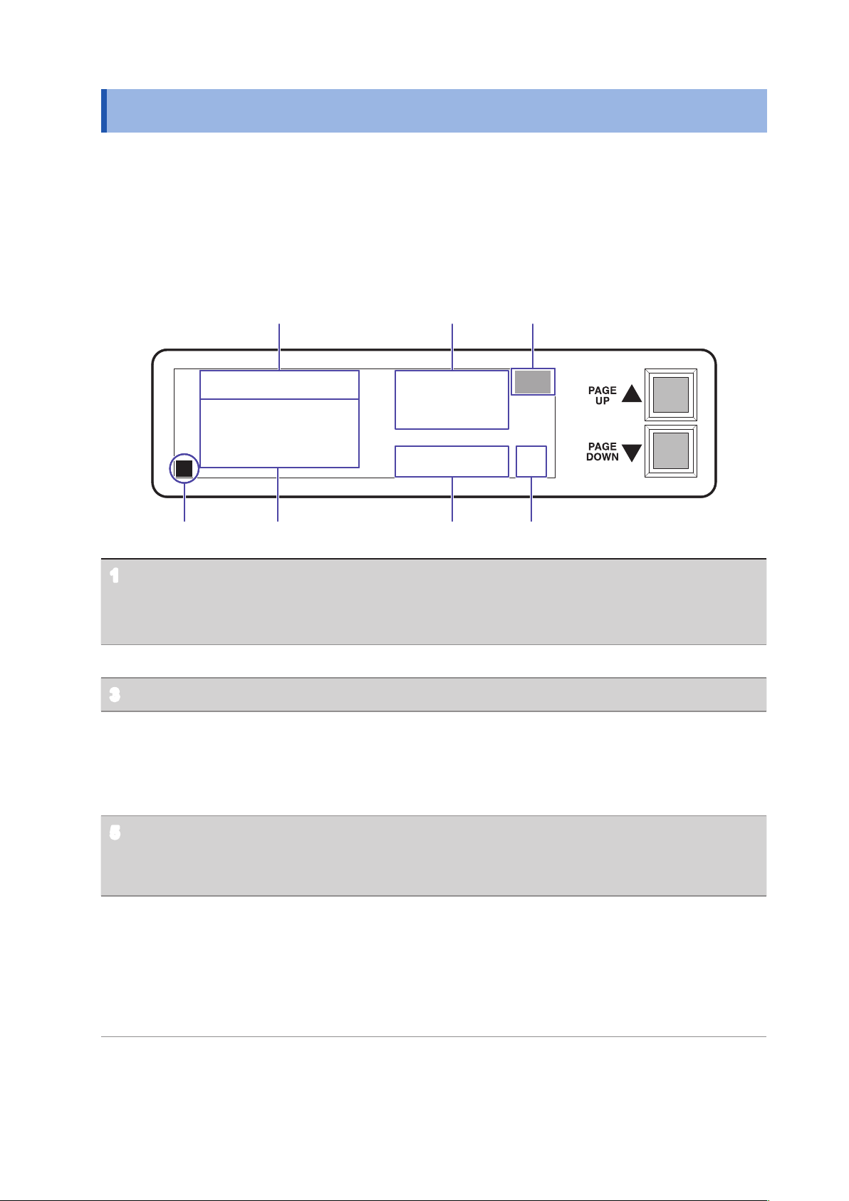
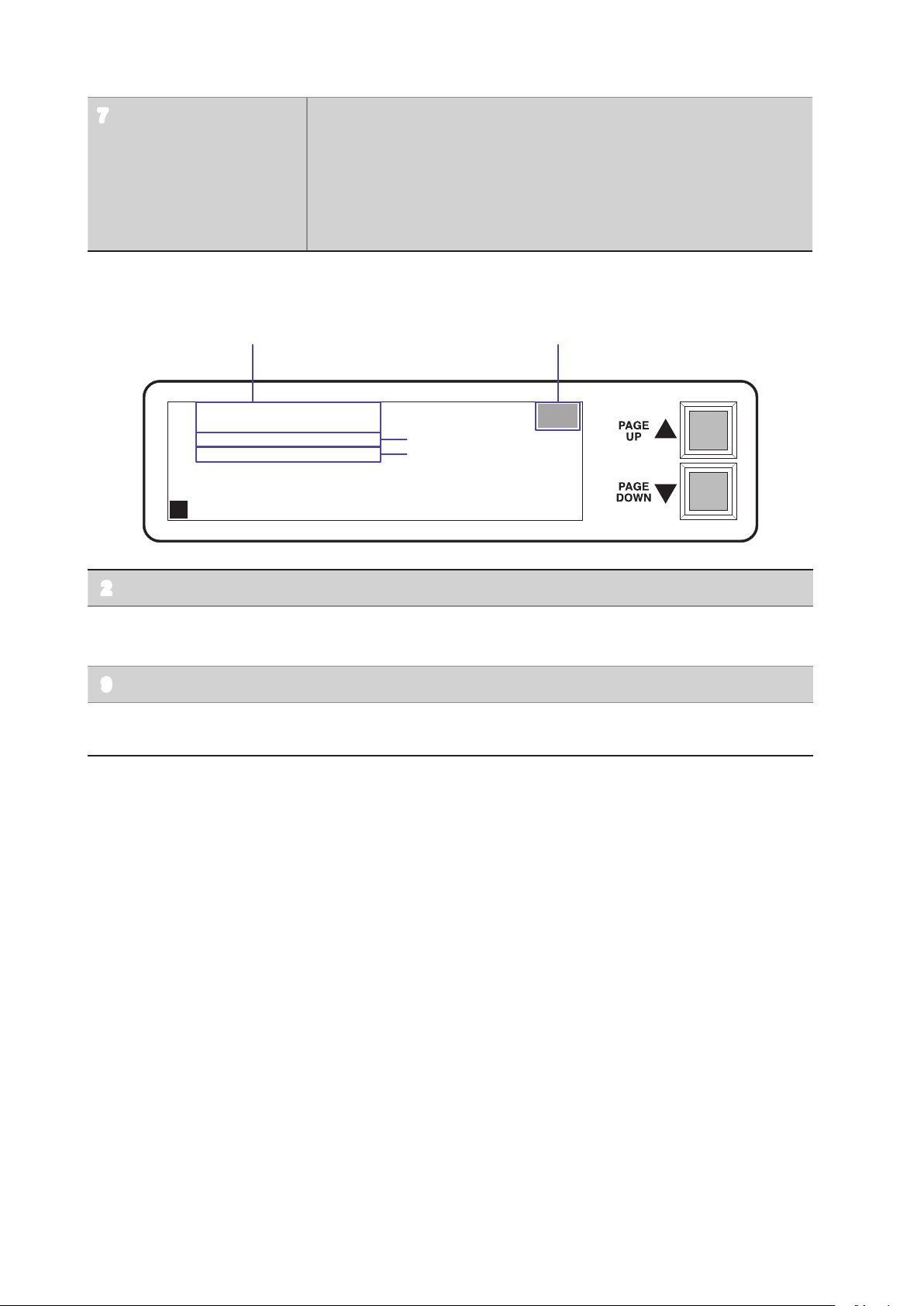
1.3 Screen Conguration
The display (LCD) consists of two display pages (Screen P1, Screen P2).
• Screen P1 is displayed when the device is turned on.
• The display pages can be scrolled using the scroll keys ([PAGE UP▲], [PAGE DOWN▼]) to the right of
the screen.
• You can select a display page directly by sending a “
interface. Refer to “3.6 Message List” (p. 34)
Screen P1: Displays output voltage settings
P1
PAG
” command from the GP-IB or RS-232C
VA (+) IR:1000.0
VB (+) IR: 250.0
TERMINAL:
OUT1:11100000
OUT2:11100000
OUT3:11100000
OUT4:11100000
L
Output voltage setting VA : Displays the power supply A circuit voltage setting.
1
VB : Displays the power supply B circuit voltage setting.
( Display example: VA (+) IR: 1000.0
Indicates that the power source’s A circuit is set to 1000.0 V.)
Temperature error display When a temperature error is detected, TEMP blinks.
2
Key lock display When the keys are locked, L is displayed.
3
Terminal output setting
4
state
Displays rows 1 through 8 of OUTn (where n indicates a value from 1
to 4), from left to right.
The setting is 0 or 1.
0 : High‑impedance
1 : ON
CLM1: 10mA
CLM2: 10mA
CLM3: 10mA
CLM4: 10mA
VMA: 1000.0
VMB: 250.0
TEMP
TEMP
OK
OK
Monitor voltage value VMA : Voltage monitor value for the power supply A circuit.
5
VMB : Voltage monitor value for the power supply B circuit.
The zero decimal point’s position is xed using zero suppression.
Voltage error alarm results
6
OK: The monitor voltage (5) error relative to the output voltage setting
(1) falls within the normal range relative to the voltage error alarm
setting (8, p. 14).
NG: The monitor voltage (5) error relative to the output voltage setting
(1) indicates an error relative to the voltage error alarm setting (8,
p. 14).
13
Screen Conguration
8
2
P2
Output current limit value CLM1 : OUT1 output current limit value setting display
7
CLM2 : OUT2 output current limit value setting display
CLM3 : OUT3 output current limit value setting display
CLM4 : OUT4 output current limit value setting display
The digit following CLM corresponds to OUT1 to 4.
( Display example: CLM1: 10mA
Indicates that the current output from OUT1 is limited to 10 mA.)
Screen P2: Displays alarms, the GP-IP address, and output setting for the device interlocked.
VA ALARM : 19
VB ALARM : 19
GPIB ADDR: 1
ILOCK DCHG: OFF
9
10
TEMP
TEMP
L
Temperature error display When a temperature error is detected, TEMP blinks.
2
Voltage error alarm setting VA ALARM : Power supply A circuit voltage error alarm setting ± (%)
8
VB ALARM : Power supply B circuit voltage error alarm setting ± (%)
GP‑IB address Refer to “Using the GP-IB Interface GP-IB” (p. 26)
9
Output setting for the
10
device interlocked
Refer to “2.7 Output Setting for the Device Interlocked” (p. 21)
14

2
Preparation and Supply Power
2.1 Installation and Connection Procedures
Be sure to read the “Operating Precautions” (p. 4) before installing and connecting the device.
3
4
6
Front Rear
Install the device. (p. 5)
1
Connect the power cord. (p. 16)
2
Connect the device to the measuring instrument. (p. 17)
3
Connect the external interface.
4
• Using the GP-IB or RS-232C interface (p. 23)
• Using the EXT I/O (p. 37)
Complete the pre-use inspection. (p. 18)
5
Be sure to inspect the device prior to use.
2
Turn the power on. (p. 19)
6
Make device settings. (p. 20)
7
(via the external interface)
Activate the power source.
8
15

Connecting the Power Cord
2.2 Connecting the Power Cord
WARNING
• Before turning the device on, make sure the supply voltage matches that indicated
on its power connector. Connection to an improper supply voltage may damage the
device and present an electrical hazard.
• To prevent an electric shock and to maintain the safety specications of this device,
connect the power cord provided only to an outlet.
• Before using the device, make sure that the insulation on the power cord is
undamaged and that no bare conductors are improperly exposed. Using the device in
such conditions could cause an electric shock, so replace the power cord with those
specied by our company.
CAUTION
To avoid damaging the power cord, grasp the plug, not the cord, when unplugging it from the
outlet or device.
Turn off the power before disconnecting the power cord.
Connection Method
1
Power inlet
2
Conrm that the device is turned off.
1
Conrm that the supply voltage
2
matches the device, and connect the
power cord to the power inlet on the
device.
Plug the power cord into the outlet.
3
This completes the process of
connecting the power cord.
16
 Loading...