


Instruction Manual
SM7860-01 to -07
SM7860-21 to -27
POWER SOURCE UNIT
February 2012 Revised edition 1 SM7860A981-01 12-02H


Contents
Introduction.................................................................................1
i
Contents
1
Confirming Packa g e Co n te n ts.............. .. ... .. ... ..................... ... .. ..1
Safety Informa tion ............. .. ... .. .. ...................... .. ... .. ...................2
Operating Precautions................................................................3
Chapter 1
Overview___________________________________ 7
1.1 Product Overview and Features .........................................7
1.2 Names and Functions of Parts ............................................8
1.3 Screen Layout ...................................................................10
Chapter 2
Preparing to Use the Device and
Supplying Power ___________________________ 11
2.1 Installation & Connection Procedures ...............................11
2.2 Connecting the Power Cord ..............................................12
2.3 Connecting the Device to the Measuring Instrument ........13
2
3
4
5
6
7
2.4 Pre-Operation Inspection ..................................................14
2.5 Turning the Power On and Off ..........................................15
2.6 Setting the Operating Conditions ......................................16
Chapter 3
Communication (GP-IB/RS-232C Interface)______ 17
3.1 Overview and Features .....................................................17
3.2 Specifications ............................................................ ........ 18
3.3 Connect a cable to the GP-IB
connector or RS-232C connector 19
3.4 Configuring the Communications Protocol ........................21
3.5 Communication Methods ..................................................22
Status Byte Register .........................................................................24
Eve n t R e g is te rs ..... ... ..................................... ...................................2 6
Error Registers ..................................................................................28
3.6 Message List .....................................................................29
3.7 Listener Specification Precautions ....................................32
Input buffer size ................................................................................32
Reading from the output buffer .........................................................32
8
9
10
11
12
付
録
索
引

ii
Contents
Chapter 4
External Control ____________________________33
4.1 External Input/Output Connector and Signals ..................33
Connector Type and Signal Pinouts .................................................34
Signal Descriptions ..........................................................................35
4.2 Timing Chart .....................................................................36
4.3 Internal Circuitry ................................................................38
Chapter 5
Specifications______________________________39
5.1 General Specifications ......................................................39
5.2 Basic Specifications ..........................................................40
5.3 Input / Output Functions ...................................................44
Chapter 6
Maintenance and Service ____________________45
6.1 Troubleshooting ................................................................ 45
Inspection and Repair ......................................................................45
6.2 Replacing the Power Fuse ................................................47
6.3 Error Displays ...................................................................48
6.4 Cleaning .................................................... ........................48
Introduction
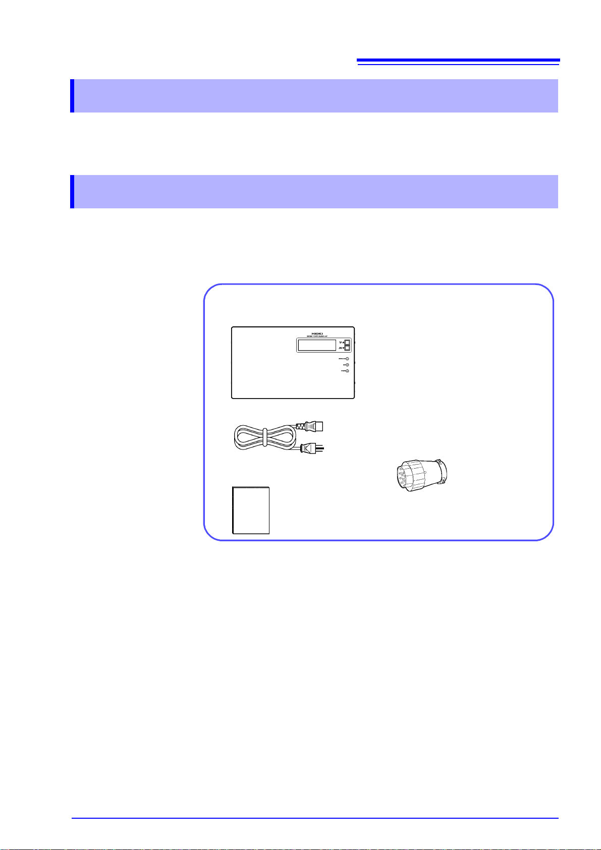
Confirm that th e se contents are provided.
□ SM7860 series Power Source Unit (1)
□ Power Cord (1)
□ Instruction Manual (1)
□ Voltage output connector
SM7860-01, -02, -21, -22.............2
SM7860-03, -04, -05, -06, -07,
-23, -24, -25, -26, -27 ......4
Thank you for purchas ing the HIOKI Model SM7860 series Power Source Unit.
To obtain maximum performance from the devic e, please read this manu al first,
and keep it handy for future reference.
Confirming Package Contents
When you receive the device, inspect it carefully to ensure that no damage
occurred during shipp ing. In particular, check the accessor ies, panel switches,
and connectors . If damage is evident, or if it fa ils to operate according to the
specifications, contact your dealer or Hioki representative.
1
Introduction
Options □ Model 9637 RS-232C Cable (9pin-9pin/Cross/1.8m)
Transportation
Notes on
□ Model 9638 RS-232C Cable (9pin-25pin/Cross/1.8m)
□ Model 9151-02 GP-IB Connector Cable (2 m)
• To ensure safe handling, when transporting the device, please use the original
box and packing materials, but do not use if the box is damaged or warped, or
if the packing materials are in poor condition or incomple te.
• When packing the device, m ake sure to disconnec t the power c ords from t he
main device.
• When transporting, avoid dropping or other excessive impact.

2
Safety Information
Safety Information
This device is des igned to comply with IEC 61010 Safety Standards, and
has been thoroughly tested for safety prior to shipment. However, mishandling during use could result in injury or death, as well as damage to the
device. Using the device in a way not described in this manual may negate
the provided safety features.
Be certain that you understand the instructions and precautions in the
manual before use. We disclaim any responsibility for accidents or injuries
not resulting directly from device defects.
This manual contain s information and warnings essential for safe operation of
the device and for maintaining it in safe operati ng condition. Be fore using it, b e
sure to carefully read the following safety precautions.
Safety Symbols
In the manual, the symbol indicates particularly important information that
the user should read before using the device.
The symbol printed on the device indicates that the user should refer to a
corresponding topic in the manual (marked with the symbol) before using
the relevant function.
Indicates a grounding termi nal.
Indicates DC (Direct Current).
Indicates AC (Alternating Current).
Indicates the ON side of the power switch.
Indicates the OFF side of the power switch.
The following symbols in this manual indicate the relative importance of cautions
and warnings.
Indicates that incorrect operation presents an extreme hazard that
could result in serious injury or death to the user.
Indicates that incorrect operation presents a significant hazard that
could result in serious injury or death to the user.
Indicates that incor rect operatio n presen ts a po ssib ility of injury to the
user or damage to the device.
Indicates advisory items related to performance or correct operation
of the device.
Other symbols
*
PA GE UP
(Bold)
( p. )
Indicates a prohibited action.
Indicates that descriptive information is provided below.
Bold characters within the text indicate operating key labels.
Indicates the location of reference information.
Operating Precautions
Follow these precaut ions to ensure s afe ope ration an d to obta in the fu ll bene fits
of the various functions.
Preliminary Checks
Before using the device for the first time, verify that it operates normally to
ensure that no damage occurred during storage or shipping. If you find any damage, contact your dealer or Hioki representative.
Device Installation
Operating temperature and humidity
Temperature and humidity range for guaranteed accuracy
3
Operating Precautions
: 0 to 40°C at 80%RH or less (non-condensing)
: 23±5°C, 80%RH or less (non-condensing)
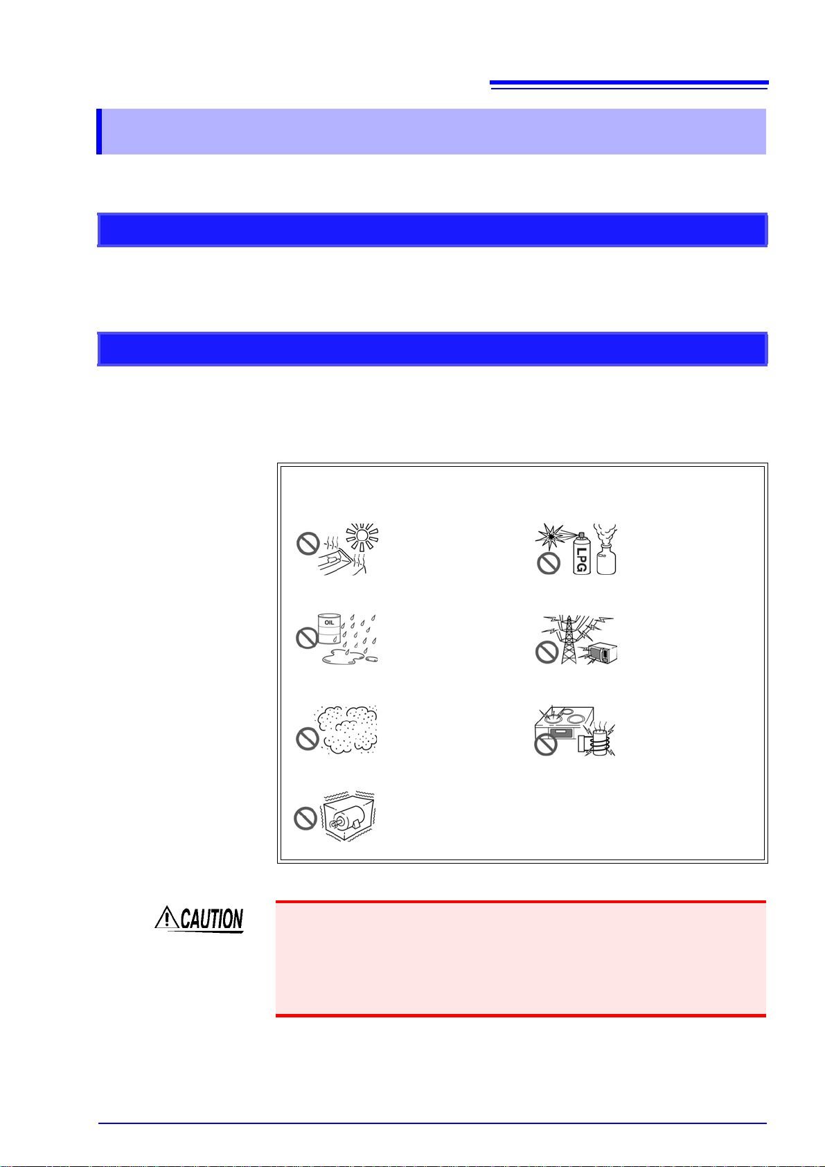
Avoid the following locations that could cause an accident or damage
to the device.
Exposed to direct sunlight
Exposed to high temperature
Exposed to water, oil,
other chemicals, or
solvents
Exposed to high humidity or condensation
Exposed to high levels of particulate dust
Subject to vibration
In the presence of corrosive or explos ive gas es
Exposed to strong electromagnetic fields
Near electromagnetic
radiators
Near electromagnetic
radiators (e.g., high-frequency induction heating systems and IH
cooking utensils)
• Do not slant the device or place it on top of an uneven surfa ce. Dropping or
knocking down the device can cause injury or damage to the device.
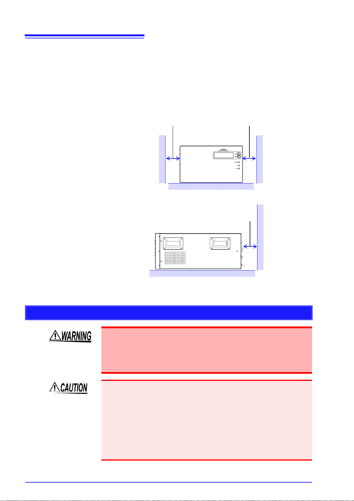
• Ventilation holes for heat radiation are provided on the si de and re ar panels of
the device. Leave sufficient space aroun d the ventilation holes and install t he
device with the holes unobstructed. Installation o f the device with the venti lation holes obstructed may cause a malfunction or fire.
4
100 mm or more
50 mm or more
50 mm or more
Operating Precautions
Installing To prevent overheating, be sure to leave the specified clearances around the
unit.
• Vents must not be obstructed.
• When rack-mounting the dev i ce, fans must be in stalle d abov e or on top of the
rack to ensure proper ventila tion. Be sure that the rack is adequately ven tilated so that the i nternal temperature remains at o r below 40°C. Continued
use of the device in a high-temperature envir onment will shorten its servic e
life. Keep the temperature as low as possible.
Handling the Device
• Do not allow the device to get wet, and do not take measurements with
wet hands. This may cause an electric shock.
• Touching any of the high-voltage points inside the device is very danger-
ous. Do not attempt to modify, disassemble or repair the device; as fire,
electric shock and injury could result.
• To avoid damage to the device, protec t it from physic al shock whe n transport-
ing and handling. Be especially careful to avoid physical shock from dropping.
Failure to observe the following precaution may result in bodily injury.
• The device weighs approxi mately 45 kg (SM7860-07, -27: approximately 32
kg). It should be move d by at least two people, who should grip it using the
handles on the left and right sides.
• The device is he avy. When transporting it, foll ow your company's workplace
safety standards to assure safety (for example, by wearing non-slip gloves and
protective footwear).

Handling the Cords
5
Operating Precautions
Before using the device, make sure that the insulation on the Connection
Cable is undamaged and that no bare conductors are improperly exposed.
Using the de v i ce i n s u c h conditions could cause an e lec t r i c shock, so con tact your dealer or Hioki representative for replacements.
• Avoid stepping on or pinching cab les, which could damage the cable insulation.
• To avoid breaking the cables, do not bend or pull them.
• To avoid damaging the power cord, grasp the plug, not the cord, when unplugging it from the power outlet.
• Keep the cables we ll away from heat sources, as bare c onductors could be
exposed if the insulation melts.
Use only the specified connection cables. Using a non-specified cable may
result in incorrect measurements due to poor connection or other reasons.
Before Connecting
• Before turning the device on, make sure the supply voltage matches that
indicated on its power connector. Connection to an improper supply voltage may damage the device and present an electrical hazard.
• To avoid electrical accidents and to maintain the safety speci ficat ion s of
this device, connect the power cord only to a 3-contact (two-conductor +
ground) outlet.
T o ensure measurements are accurate,
• Warm up the device an hour or more before use.
• The device should be calibrated once a year.

6
Operating Precautions

1.1 Product Overview and Features
Overview Chapter 1
1.1 Product Overview and Features
The SM7860-01 to -07 and SM786 0-21 to -27 ar e power supp ly units d esigned
for use with the Model SM7810 or SM7810-20 Super MΩ HiTester. They support
bipolar, multi-channel output and are compatible with multi-channel systems.
Used in combination with the Model SM7810 or SM7810-20 Super MΩ HiTester,
they are ideal for use in automated testing and measurement of capacitors.
Bipolar, multi-channel output
The device delive rs an 8-channel, positive/negative power supply, allowing an
optimized test ing line to be built using th e smallest possible number of power
supplies.
7
Independent on/off output switching and current limitations
for all channels
Since each channel has its own output on/off switch, it is possible to control voltage application without an external circuit (allowing charging and dis charging).
Use of semiconduc tor switches elimina tes the need for mainten ance. Additionally, the ability to limit current (to 50 mA) for individual channels means the measurement of other channe ls won't be affected when a target workpiece has a
short.
Output current capacity: 50 mA/channel
High-capacity capacitors can be charged rapidly, and the number of charges can
be reduced.
Output voltage: 1,000 V/channel
Devices are available with output voltages of up to ±1,000 V.
Standard interfaces
Devices ship standard with external I/O, GP-IB, and RS-232C interfaces for
sequencing. Interfaces are used to configure and power the devices.
Inter-lock Function

8
LCD screen
The screen uses a 2-page
layout to display setting values and setting status inf ormation.
"1.3 Screen Layout" (p.10)
Front Panel
Scroll keys (PAGE UP▲/ PAGE DOWN▼)
Used to scroll through the display pages.
"1.3 Screen Layout" (p.10)
The scroll keys are also used to se t the GP-IB add ress.
(p.21)
Inter-lock indicator
Lights up when the interlock is
on.
V oltage output indicator
Lights up when a voltage is being output.
Power indicator
Lights up when the d evi ce is on.
Rear Panel
Power inlet
Connect the supplied power cord
here. (p.12)
Fuse holder
Allows the fuse to be replaced.
(p.47)
RS-232C connector
Connect to a compute r when
using the RS-232C interface.
(p.19)
EXT I/O connector
The external I/O connector
can be used to control the
device.
(p.33)
Voltage output terminal
Connect the included voltage
output connector.
(p.13)
Vent
Keep clear of obstructions.
POWER switch
Turns the device o n and off .
: Power On
: Power Off
(p.15)
GP-IB connector
Connect to a compu ter whe n using the
GP-IB interface.
(p.19)
GND terminal
Serves as the ground terminal.
The GND terminal is connected
to the device’s enclosure.
1.2 Names and Functions of Parts
1.2 Names and Function s of Parts
9
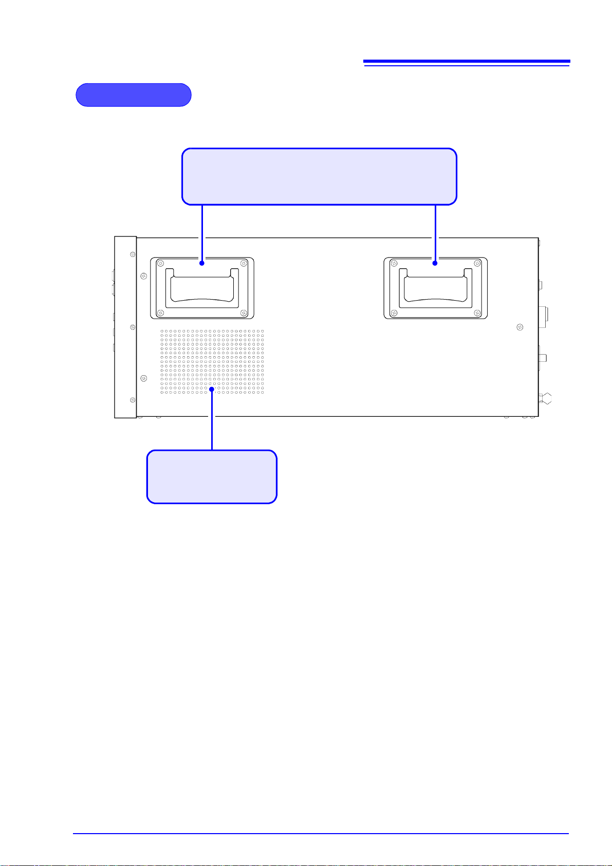
Side Panel
Handle
It should be moved by at least two p eople, who shoul d grip it using
the handles on the left and right sides.
Vent
Keep clear of obstructions.
1.2 Names and Functions of Parts

10
VA (+) IR:1000.0
VB (+) IR: 250.0
TERMINAL:
OUT1:11100000
OUT2:11100000
OUT3:11100000
OUT4:11100000 VMA:1000.0 OK
VMB: 250.0 OK
■ Screen P1 : Displays output voltage settings.
■ Screen P2: Alarm/GP-IB address setting display
Output voltage setting
VA: Displays the power supply A circuit voltage setting.
VB: Displays the power supply B circuit voltage setting.
Temperature error display
When a temperature error is d ete cte d,
"TEMP" flashes in reverse video.
Terminal output setting state
The setting is 0 or 1.
From left to right, OUTn row 1 → row 8
0: High-impedance
1: ON
Monitor voltage value
VMA: Displays the voltage
monitor value for the
power supply A circuit.
VMB: Displays the voltage
monitor value for the
power supply B circuit.
*Fixed-po int, zero-suppr essed.
Voltage error alarm results
VA ALARM: 19
VB ALARM: 19
GPIB ADDR: 1
Voltage error alarm setting
VA: Power supply A circ uit voltage error alar m setting ± (% )
VB: Power supply B circ uit voltage error alar m setting ± (% )
OK: The monitor voltage error
relative to the output voltage setting falls with in the
normal range relative to
the voltage error alarm
setting.
NG: The monitor voltage error
relative to the output voltage setting indicates an
error relative to the voltage
error alarm setting.
Temperature error display
When a temperature error is
detected, "TEMP" flashes in reverse video.
GP-IB address
L
Key lock display
When the keys are
locked, flashes
in reverse video.
L
TEMP
TEMP
L
TEMP
TEMP
1.3 Screen Layout
1.3 Screen Layout
The LCD screen cons ists of two dis play pa ges. W hen th e SM78 60 i s turne d on,
page 1 is shown.
The scroll keys on th e front of the device (PA GE UP ▲/ PAG E D OW N▼) are
used to scroll among the di splay pages, which can also be selected directly by
sending the “
See: Message List "PAG" (p.30)
PAG” command from the GP-IB or RS-232C interface.

11
8
Install this device (p.3)
1
Rear PanelFront Panel
Turn the power on (p.15)
6
Connect the external interface
4
• Using the GP-IB or RS-232C interface
(p.17)
• Using the EXT I/O (p.33)
Connect the power cord (p.12)
2
Make device settings (p.16)
(via the external interface)
7
Connect the device to the measuring instrument. (p.13)
3
Be sure to complete the pre-operation inspection (p.14) before
using the device
5
Activate the power source
2
4
6
3
2.1 Installation & Connection Procedures
Preparing to Use the Device
and Supplying
Power Chapter 2
2.1 Installation & Connection Procedures
Be sure to read the "Operating Precautions" (p.3) befo re installing and connecting
this device.
12
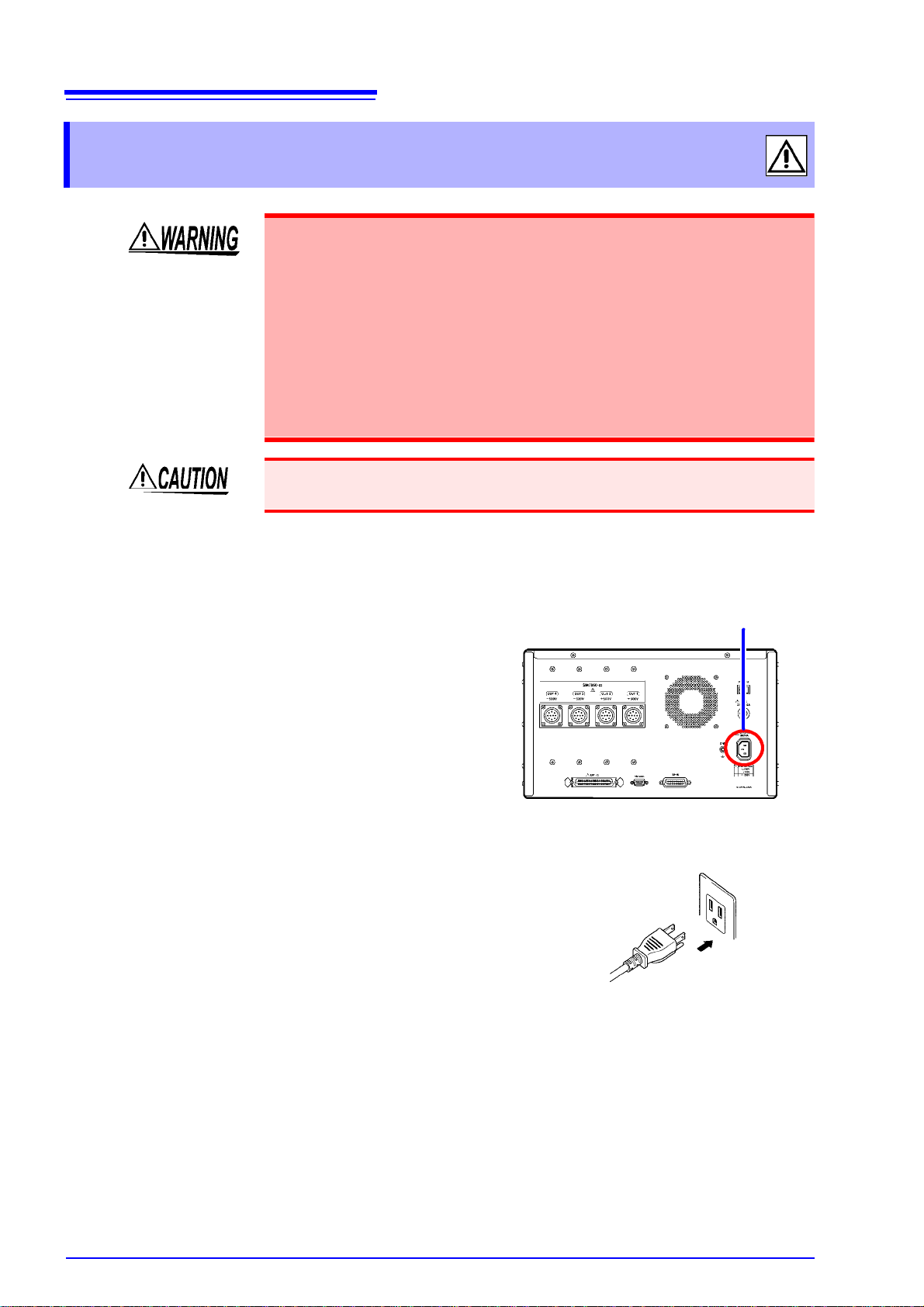
Rear Panel
1 Confirm that the device is turned off.
2 Confirm that the mains supply voltage
matches the device, and connect the
power cord to the power inlet on the
device.
3 Plug the power cord into the mains outlet.
Power inlet
2.2 Connecting the Power Cord
2.2 Connecting the Power Cord
• Before turning the device on, make sure the supply voltage matches that
indicated on its power connector . Connection to an improper supply voltage may damage the device and present an electrical hazard.
• To avoid electrical accidents and to maintain the safety specific at ion s of
this device, connect the power cord only to a 3-contact (two-conductor +
ground) outlet.
• Before using the device, make sure that the insulation on the power cord
is undamaged and that no bare conductors are improperly exposed.
Using the device in such conditions could cause an electric shock, so
contact your dealer or Hioki representative for replacements.
To avoid damaging the po wer cord, grasp the plug, not the cord, wh en unplugging it from the power outlet.
Turn off the power before disconnecting the power cord.
Connection Methods

2.3 Connecting the Device to the Measuring Instrument
Rear Panel
1 Confirm that the device is turned off.
2 Connect the included voltage output con-
nector to the voltage output terminal on
the rear of the device.
Voltage output terminal
6 5 47
3
2
10
8
9
1
Voltage output pin assignments
(View of terminal on device)
*1 On the SM7860-05, -06, -2 5, an d - 26, ser v es as t he di s ch argin g
terminal.
*2 On the SM7860-05, -06, -07, -25, -26 and -27, serves as the dis-
charging terminal.
Pin No. OUT1
Circuit A
OUT2
*1
Circuit A
OUT3
Circuit B
OUT4
*2
Circuit B
1 CH1 CH1 CH1 CH1
2 CH2 CH2 CH2 CH2
3 CH3 CH3 CH3 CH3
4 CH4 CH4 CH4 CH4
5 CH5 CH5 CH5 CH5
6 CH6 CH6 CH6 CH6
7 CH7 CH7 CH7 CH7
8 CH8 CH8 CH8 CH8
9 NC NC NC NC
10 COM COM COM COM
2.3 Connecting the Device t o the Measuring
Instrument
To avoid electric shock or damage to the equ ipment, always observe the
following precautions when connecting to voltage output terminal.
• Always turn off the power to the device and to any dev ices to be con-
nected before connecting the voltage output connectors.
To avoid damaging the device, be sure to observe the following precautions:
• Do not connect the device to a load with a charge in exc ess of the output v oltage range.
• Do not connect the device to a load with a charge that has the opposite polarity
of the output voltage range.
• Do not connect the device to a load that has a charge when the device's power
supply is turned off.
13
Connection Methods
Specifications
 Loading...