

Page 1
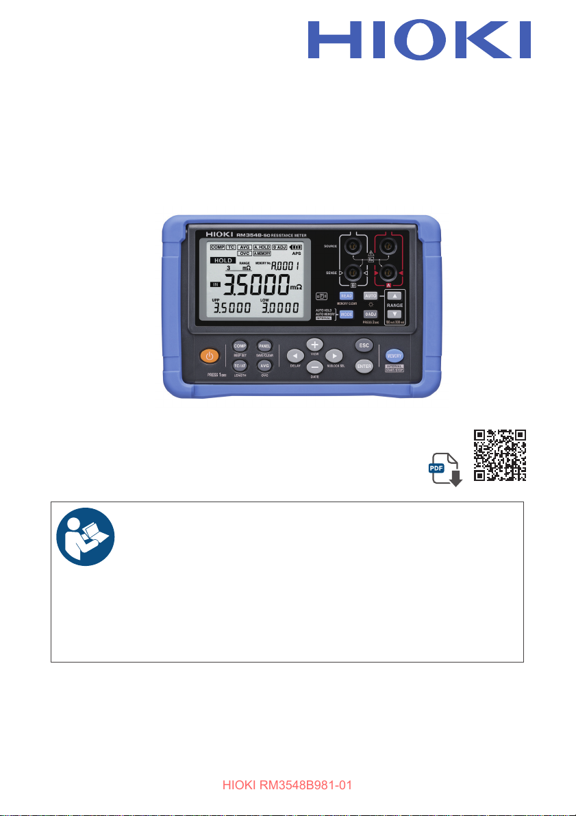
RM3548-50
HIOKI RM3548B981-01
Instruction Manual
RESISTANCE METER
Check for the latest edition and
other language versions.
Safety Notes
Component Names and
Operation Overview
Basic Measurement
Oct. 2024 Revised edition 1
RM3548B981-01
Read carefully before use.
Keep for future reference.
X
p.4 Troubleshooting
X
p.16
X
p.41
Error display and
actions
[600667291]
X
X
p.126
p.132
EN
Page 2
How to use the Instruction Manual
HIOKI RM3548B981-01
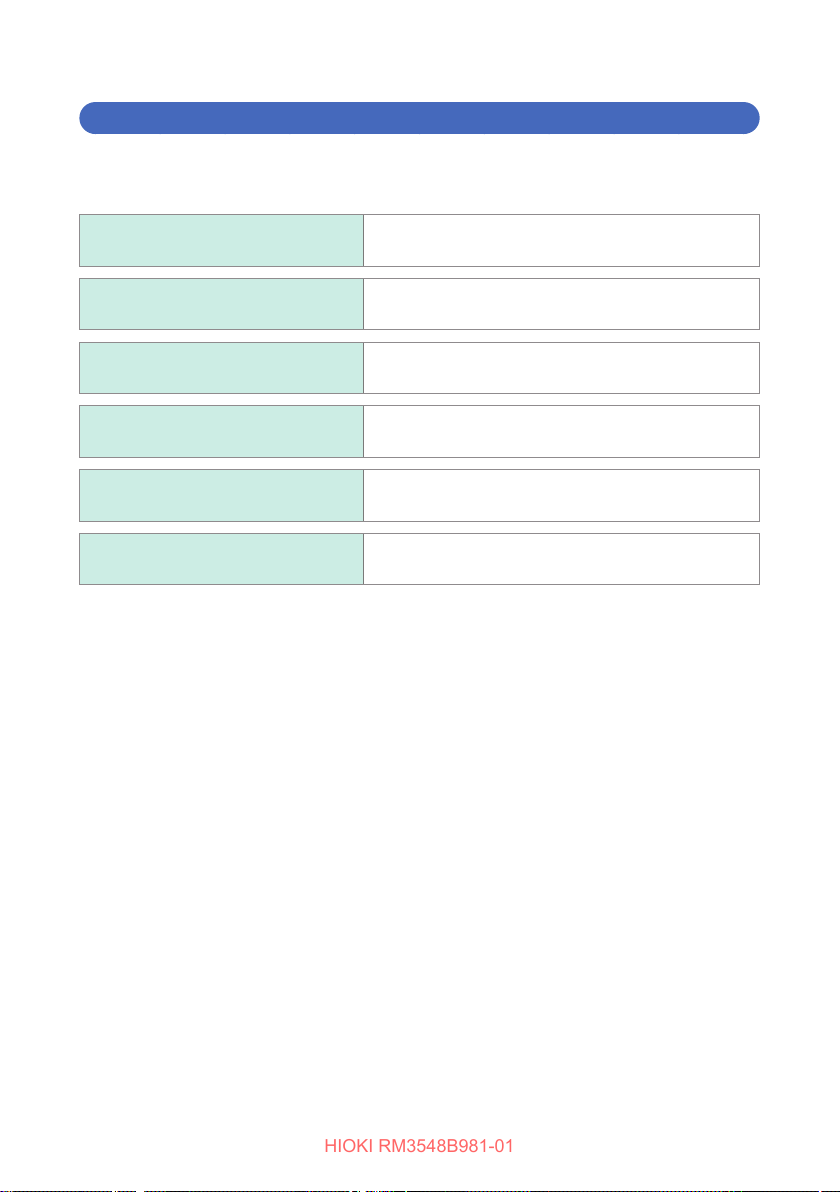
See below, as appropriate:
Be sure to always read the
following sections.
When you wish to use the
instrument immediately
When you need further information
on the various functions
To nd out about instrument
specications
If the instrument does not operate
as intended or expected
For detailed information related to
resistance measurement
“Safety Notes” (p. 4)
“Usage Notes” (p. 7)
“Overview” (p. 15)
Refer to the “Contents” (p. i) and/or “Index”
(p. Ind.1) to nd the desired function.
“Specications” (p. 111)
“Troubleshooting” (p. 126)
“Appendix” (p. Appx.1)
1
2
3
4
5
6
7
RM3548B981-01
8
9
10
Page 3

HIOKI RM3548B981-01
Page 4

Contents
HIOKI RM3548B981-01
Introduction ........................................................................................1
Verifying Package Contents .............................................................2
Options ....................................................................................... 3
Safety Notes ....................................................................................... 4
Usage Notes ....................................................................................... 7
1 Overview 15
1
2
1.1 Overview and Features .................................................15
1.2 Component Names and Operation Overview ............. 16
Power-on settings ....................................................................21
1.3 Flow of Measurement ...................................................22
1.4 Screen Layout ...............................................................23
1.5 Checking the Measurement Target .............................26
2 Preparing for Measurement 29
2.1 Loading or Replacing the Batteries ............................30
2.2 Connecting the Z3210 Wireless Adapter (Option) .....32
2.3 Attaching the Z5041 Protector ..................................... 33
2.4 Attaching the Strap ....................................................... 34
2.5 Connecting the Test Leads ..........................................35
2.6 Connecting the Z2002 Temperature Sensor
(When Using TC or ΔT) ................................................. 36
2.7 TurningthePowerOn/O .............................................37
Turning the power on ...............................................................37
Turning the power o ...............................................................37
Automatic power o with auto power save (APS) .................... 38
Disabling auto power save (APS) ............................................38
2.8 Pre-measurement Inspection .......................................39
3
4
5
6
7
8
9
3 Basic Measurement 41
3.1 Setting the Measurement Range .................................42
3.2 Connecting the Test Leads to the Measurement
10
Appx. Ind.
Target .............................................................................44
i
Page 5

Contents
HIOKI RM3548B981-01
3.3 Reading the Measured Value .......................................45
Switching the display................................................................45
Verifying measurement errors ..................................................46
Holding a measured value .......................................................48
Memorizing a measured value ................................................. 48
4 Customizing Measurement Conditions 49
4.1 Using Zero Adjustment.................................................50
4.2 Stabilizing Measured Values (Averaging Function) ...55
4.3 CompensatingforThermalEects
(Temperature Correction (TC)) ..................................... 56
4.4 CompensatingforThermalEMFOset(Oset
Voltage Compensation Function: OVC Function) ...... 58
4.5 Setting the Delay Time for Measurement
(Delay Function) ............................................................ 60
4.6 Switching the Measurement Current
(In the 300m
Range) ................................................... 62
Ω
5 Judgment and Conversion Functions 65
5.1 Judging Measured Values (Comparator Function) ....66
5.2 Performing Temperature Rise Test (Temperature
5.3 Measuring the Length of a Conductor
ii
Judging based on upper and lower limit values (ABS mode) .. 69
Judging based on a reference value and allowable range
(REF% mode) ..........................................................................70
Conrming judgment results with the red backlight and
sound (judgment sound function) ............................................. 71
Verifying a judgment on a handheld device
(L2105 LED Comparator Attachment option) ..........................72
ConversionFunction(∆T)) ........................................... 73
(Length Conversion Function) ..................................... 76
Page 6

6 Panel Save and Load (Saving and Loading
HIOKI RM3548B981-01
Measurement Conditions) 79
6.1 Saving Measurement Conditions
(Panel Save Function) ..................................................80
6.2 Loading Measurement Conditions
(Panel Load Function) ..................................................81
6.3 Clearing the Contents of a Panel .................................82
Contents
1
2
7 Communications Function 83
7.1 Communicating With a Mobile Device ........................84
Enabling/disabling the wireless communications function ....... 86
7.2 Z3210-to-Excel Direct Data Entry Function
(Excel Direct Input Function, HID Function) ...............87
Enabling/disabling the HID function ......................................... 88
8 Memory Function (Saving and Exporting
Measurement Data to a PC) 91
8.1 SavingDataatSpeciedTime(ManualMemory) ......93
8.2 Saving Data Automatically When Measured
Values Stabilize (Auto-Memory) ..................................94
8.3 Saving Data at Fixed Intervals
(Interval Memory Function) .......................................... 95
8.4 Displaying Saved Measurement Data
(Memory Display Function) .......................................... 97
8.5 Clearing Measurement Data (Memory Clear) .............98
8.6 Exporting Saved Measurement Data to a PC
(USB Mass Storage Mode) .........................................102
9 System Settings 105
9.1 DisplayingtheDateandTimeVericationScreen ..105
9.2 Setting the Clock ......................................................... 106
9.3 Backlight ...................................................................... 107
Turning on/o the backlight .................................................... 107
Enabling/disabling automatic backlighing shuto ................... 107
9.4 Initializing (Reset) .......................................................108
Default settings ......................................................................109
3
4
5
6
7
8
9
10
Appx. Ind.
iii
Page 7

Contents
HIOKI RM3548B981-01
10 Specications 111
10.1 GeneralSpecications ............................................... 111
10.2 MeasurementSpecications ..................................... 112
Accuracy ................................................................................ 115
10.3 FunctionSpecications ............................................. 116
10.4 Interface ....................................................................... 124
11 Maintenance and Service 125
11.1 Troubleshooting ..........................................................126
Q&A (frequently asked questions and answers) ....................126
Error display and actions........................................................132
11.2 Repair and Inspection ................................................134
11.3 Replacing Fuses .........................................................135
11.4 Disposing of the Instrument ......................................136
Appendix Appx.1
Appx. 1 Block Diagram ...............................................Appx.1
Appx. 2 Four-Terminal (Voltage-Drop) Method .........Appx.2
Appx. 3 DC Method and AC Method ..........................Appx.3
Appx. 4 Temperature Correction Function (TC) .......Appx.4
Appx. 5 Temperature Conversion (ΔT) Function ......Appx.7
Appx.6 EectofThermoelectromotiveForce
(Thermal EMF) ................................................Appx.8
Appx. 7 Zero Adjustment .......................................... Appx.11
Appx. 8 Unstable Measurement Values ...................Appx.17
Appx. 9 Locating Short-Circuits on a PC Board ..... Appx.27
Appx. 10 Test Lead Options .......................................Appx.28
Appx. 11 Calibration .................................................... Appx.31
Index Ind.1
iv
Page 8
Introduction
HIOKI RM3548B981-01
Introduction
Thank you for purchasing the HIOKI RM3548-50 Resistance Meter.
To obtain maximum performance from the instrument, please read this manual rst,
and keep it handy for future reference.
Product registration
Register your product in order to receive important product
information.
https://www.hioki.com/global/support/myhioki/registration/
Trademarks
• Excel is a trademark of the Microsoft group of companies.
• The Bluetooth® word mark and logos are registered trademarks owned by Bluetooth
SIG, Inc. and any use of such marks by Hioki E.E. Corporation is underlicense.
Other trademarks and trade names are those of their respective owners.
• IOS is a registered trademark of Cisco Systems, Inc. and/or itsaliates in the
United States and certain other countries.
• Android, Google Play, and Google Chrome are trademarks of Google,Inc.
1
Page 9
Verifying Package Contents
電池
電池
HIOKI RM3548B981-01
Verifying Package Contents
• When you receive the instrument, inspect it carefully to ensure that no damage
occurred during shipping. In particular, check the accessories, panel switches,
and connectors. If damage is evident, or if it fails to operate according to the
specications, contact your authorized Hioki distributor or reseller.
• When transporting the instrument, use the same packaging materials used for the
delivery to you.
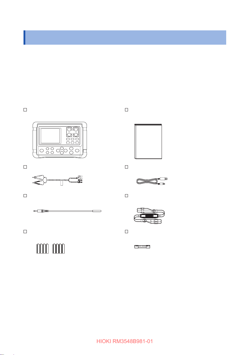
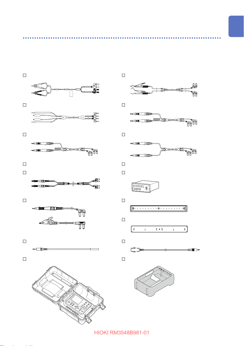
Check the package contents as follows.
RM3548-50 Resistance Meter Instruction Manual
L2107 Clip Type Leads (p. 35) USB Cable (A-miniB type)
Z2002 Temperature Sensor (p. 36) Strap
LR6 Alkaline battery × 8
2
Spare fuse (F2AH/250 V)
Page 10
Verifying Package Contents
JAPAN
HIOKI RM3548B981-01
Options
The options listed below are available for the instrument. To order an option, please
contact your authorized Hioki distributor or reseller. Options are subject to change.
Please check Hioki’s website for the latest information. (p. Appx.28)
L2107 Clip Type Leads 9467 Large Clip Type Lead
9453 Four Terminal Lead 9772 Pin Type Lead
9465-10 Pin Type Lead 9465-11 Pin Type Lead
9465-90 Tip Pin (for 9465-10, 9465-11) 9772-90 Tip Pin (for 9772)
L2141, L2142 Pin Type Lead Z3210 Wireless Adapter
L2140 Test Lead 9454 Zero Adjustment Board
Z2002 Temperature Sensor L2105 LED Comparator Attachment
C1015 Carrying Case Z5041 Protector
Z5038 0 Adjustment Board
3
Page 11
Safety Notes
HIOKI RM3548B981-01
Safety Notes
The instrument is designed to conform to IEC 61010 Safety Standards, and has been
thoroughly tested for safety prior to shipment. However, using the instrument in a way
not described in this manual may negate the provided safety features.
Before using the instrument, be certain to carefully read the following safety notes.
DANGER
Mishandling during use could result in injury or death, as well
as damage to the instrument. Be certain that you understand the
instructions and precautions in the manual before use.
WARNING
With regard to the electricity supply, there are risks of electric shock,
heatgeneration,re,andarcdischargeduetoshortcircuits.If
persons unfamiliar with electricity measuring instruments are to use
the instrument, another person familiar with such instruments must
supervise operations.
This manual contains information and warnings essential for safe operation of
the instrument and for maintaining it in safe operating condition. Before using the
instrument, be certain to carefully read the following safety notes.
4
Page 12
Safety Notes
HIOKI RM3548B981-01
Notation
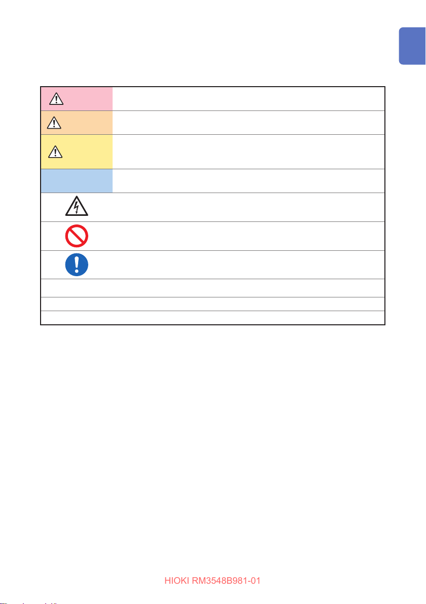
In this manual, the risk seriousness and the hazard levels are classied as follows.
DANGER
WARNING
CAUTION
IMPORTANT
*
p. Indicates the location of reference information.
[ ] An item enclosed by [ ] indicates a key name.
Indicates an imminently hazardous situation that will result in death or
serious injury to the operator.
Indicates a potentially hazardous situation that may result in death or
serious injury to the operator.
Indicates a potentially hazardous situation that may result in minor
or moderate injury to the operator or damage to the instrument or
malfunction.
Indicates information related to the operation of the instrument or
maintenance tasks with which the operators must be fully familiar.
Indicates a high voltage hazard. Failure to verify safety or improper
handling of the instrument could lead to an electric shock, burn, or death.
Indicates prohibited actions.
Indicates the action which must be performed.
Additional information is presented below.
5
Page 13
Safety Notes
HIOKI RM3548B981-01
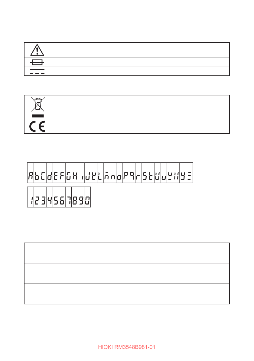
Symbolsaxedtotheinstrument
Indicates cautions and hazards. When the symbol is printed on the instrument,
refer to a corresponding topic in the Instruction Manual.
Indicates a fuse.
Indicates DC (Direct Current).
Symbols for various standards
Indicates that the product is covered by the Directive on Waste Electrical and
Electronic Equipment (WEEE) in EU member nations. Dispose of the product by
local regulations.
Indicates that the instrument conforms to regulations required by the EU Directive.
Screen display
The instrument uses the following screen displays.
A B C D E F G H I J K L M N O P Q R S T U V W X Y Z
1 2 3 4 5 6 7 8 9 0
Accuracy
We dene measurement tolerances in terms of f.s. (full scale), rdg. (reading) and dgt.
(digit) values, with the following meanings:
f.s.
rdg.
dgt.
See: “Accuracy calculation examples” (p. 115)
6
(Maximum display value)
This is usually the maximum display value. In the instrument, this indicates the
currently used range.
(Reading or displayed value)
The value currently being measured and indicated on the measuring
instrument.
(Resolution)
The smallest displayable unit on a digital measuring instrument, i.e., the input
value that causes the digital display to show a “1”.
Page 14
Usage Notes
HIOKI RM3548B981-01
Usage Notes
Follow these precautions to ensure safe operation and to obtain the full benets of
the various functions.
Use of the instrument should conrm not only to its specications, but also to the
specications of all accessories, options, batteries, and other equipment in use.
Checking before use
Before using the instrument the rst time, verify that it operates normally to ensure
that no damage occurred during storage or shipping. If you nd any damage, contact
your authorized Hioki distributor or reseller.
DANGER
Before using the instrument, check that the coating of the test leads
or cables are neither ripped nor torn and that no metal parts are
exposed. Using the instrument under such conditions could result
inelectrocution.Replacethetestleadswiththosespeciedbyour
company.
Installation
Installing the instrument in inappropriate locations may cause a malfunction of
instrument or may give rise to an accident. Avoid the following locations.
• Exposed to direct sunlight or high temperature
• Exposed to corrosive or combustible gases
• Exposed to water, oil, chemicals, or solvents
• Exposed to high humidity or condensation
• Exposed to a strong electromagnetic eld or electrostatic charge
• Exposed to high quantities of dust particles
• Near induction heating systems (such as high-frequency induction
heating systems and IH cooking equipment)
• Susceptible to vibration
IMPORTANT
Accurate measurement may be impossible in the presence of strong magnetic
elds, such as near transformers and high-current conductors, or in the presence of
strong electromagnetic elds such as near radio transmitters.
CAUTION
7
Page 15
Usage Notes
HIOKI RM3548B981-01
Handling precautions
WARNING
• Do not allow the instrument to get wet, and do not use it with wet
hands. This may cause electric shock accident.
• Do not modify, disassemble, or repair the instrument. This may
resultinre,electricshockaccident,orinjury.
CAUTION
• Do not place the instrument on an unstable or slanted surface. It may
drop or fall, causing injury or instrument failure.
• To avoid any damage to the instrument, avoid any vibration or shock
during transport or handling. Especially, be careful not to drop or fall the
instrument which will cause shock.
• To avoid any damage to the instrument, do not input voltage or current to
any measurement, TEMP.SENSOR, or COMP.OUT terminals.
Precautions during shipment
Observe the following during shipment.
Hioki cannot be responsible for damage that occurs during shipment.
• During shipment of the instrument, handle it carefully so that it is not
damaged due to a vibration or shock.
• To avoid damage to the instrument, remove the accessories and optional
equipment from the instrument during shipment.
If the instrument is not used for an extended period of time
IMPORTANT
To avoid corrosion and/or damage to the instrument due to battery leakage, remove
the batteries from the instrument if it is to be kept in storage for an extended period.
8
CAUTION
Page 16
Handling leads and cables
HIOKI RM3548B981-01
To avoid electrical shock accident, do not short test leads where
voltage is applied.
• Avoid stepping on or pinching the leads, which could damage the lead
insulation.
• To avoid damaging the cables, do not bend or pull the base of cables and
the leads.
• When removing a connector, hold its plug portion, not its cable, to prevent
a wire disconnection.
• The ends of pin type leads are sharp. Be careful to avoid injury.
• Melted lead wire is dangerous because its metal part is exposed.
Be careful not to allow contact between the lead wire and the heat
generating portion.
• The Z2002 Temperature Sensor is precision-machined. Excessively high
voltage pulses or static electricity may damage the sensor.
• Do not apply an excessive impact to the tip of the Z2002 Temperature
Sensor or bent the lead wire. It may cause failure or wire disconnection.
Usage Notes
DANGER
CAUTION
IMPORTANT
• Do not use any test lead or temperature sensor other than the ones specied by
our company. It may result in inaccurate measurement due to poor contact or
other reasons.
• If the jack of a test lead or the temperature sensor is dirty, wipe it o. Otherwise,
the contact resistance will increase, aecting the temperature measurement.
• Be careful so that the temperature sensor connector does not come o. (The
temperature correction or conversion function will not work if the connector
comes o.)
Before attaching the strap
Use the four attachment points on the instrument to attach the strap
securely. Otherwise, the instrument may drop during carrying, damaging
the instrument.
CAUTION
9
Page 17
Usage Notes
HIOKI RM3548B981-01
Batteries
Poor performance or damage from battery leakage could result. Observe
the cautions listed below.
WARNING
• Do not short circuit, charge, disassemble, or incinerate batteries. Doing
so may cause an explosion and is dangerous.
• Remove any test leads before replacing batteries.
• After the replacement, be sure to reattach the cover.
CAUTION
• Do not use both new and old batteries or dierent types of batteries
together.
• Be careful to observe battery polarity. Otherwise, poor performance or
damage from battery leakage could result.
• Do not use batteries after their recommended expiry date.
• Do not allow used batteries to remain in the instrument.
• To avoid corrosion and/or damage to the instrument due to battery
leakage, remove the batteries from the instrument if it is to be kept in
storage for an extended period.
IMPORTANT
• When
possible. When
Replace the batteries.
• Be sure to turn the power o after using it.
• In this manual, the “batteries” are those used to power the instrument.
• Do not use any batteries other than the specied type (LR6 Alkaline batteries,
HR6 Nickel-metal hydride batteries).
• Dispose of batteries in accordance with local regulations.
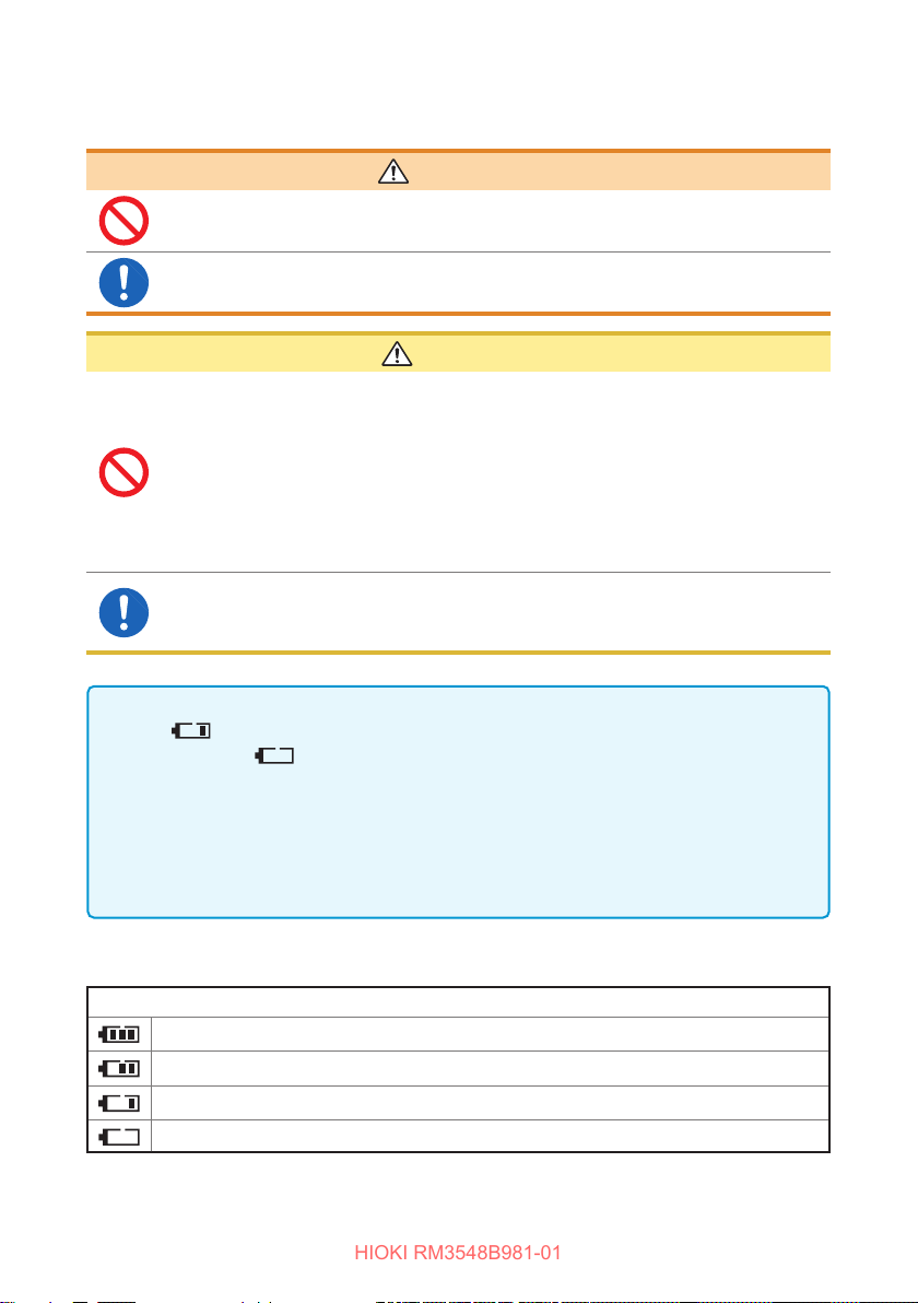
Remaining battery level indicator
The battery is fully charged.
As the remaining amount of batteries becomes low, the bars disappear from the left.
The battery becomes low. Replace the batteries as soon as possible.
(Blinking) There is no battery remaining. Replace the batteries with new ones.
10
is lit, the battery becomes low. Replace the batteries as soon as
is blinking, the battery becomes too low for measurement.
Indication
Page 18
Before connecting test leads
HIOKI RM3548B981-01
DANGER
To avoid electric shock or short-circuit accident, turn any
measurementtargetobeforeconnectingtestleads.
Before connecting the L2105 LED Comparator Attachment
CAUTION
• To prevent the instrument and the L2105 LED Comparator Attachment
from breaking down, turn the power o before connecting the L2105 LED
Comparator Attachment.
• The COMP.OUT terminal is for the L2105 only. Do not connect any
terminal other than the L2105.
• Connect the temperature sensor securely. Otherwise, the specications
may not be met.
• When a tie band is used, do not tighten the test lead excessively.
It could damage the test lead.
• Do not perform the following as they could damage the core or coating of
a cable.
Twisting or pulling the cable
Connecting the cable around the L2105 LED Comparator Attachment
by bending it compactly
Usage Notes
Before connecting the Z2002 Temperature Sensor
Connect the Z2002 Temperature Sensor securely. Otherwise,
specicationsmaynotbemetorafailuremayoccur.
• To prevent the instrument and the Z2002 Temperature Sensor from
breaking down, turn the power o before connecting the Z2002
Temperature Sensor.
• Insert the Z2002 Temperature Sensor all the way into the TEMP.SENSOR
terminal. Otherwise, the measurement may have a large error.
IMPORTANT
If the jack of the Z2002 Temperature Sensor is dirty, wipe it o. Otherwise, the
temperature measurement may have an error.
WARNING
CAUTION
11
Page 19
Usage Notes
HIOKI RM3548B981-01
Measurement precautions
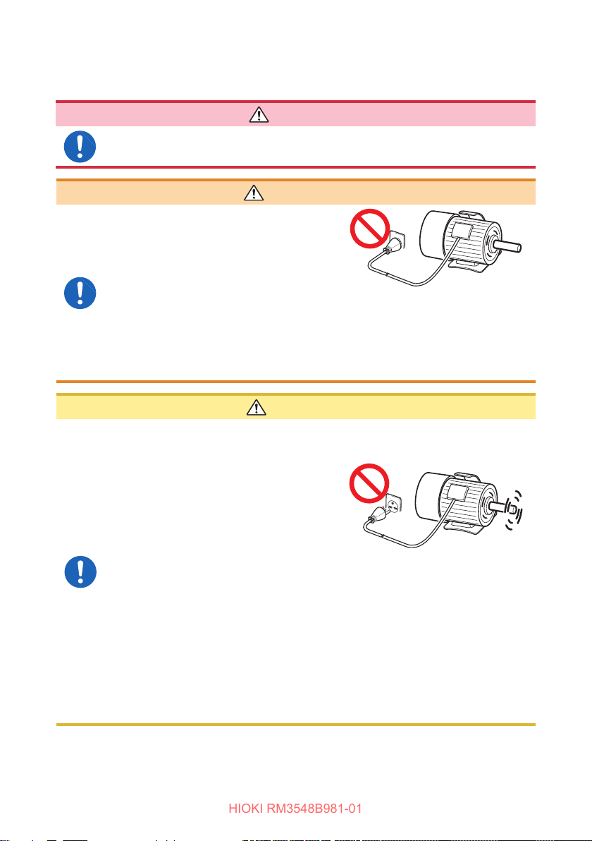
To avoid electrical shock accident, do not short test leads where
voltage is applied.
• To prevent electric shock accident
or damage to the instrument, do not
apply voltage to any measurement
terminal. To avoid electrical accident,
remove power from the measurement
target before measurement.
• Electrical sparks may occur at the moment of connecting/disconnecting
the power cable to/from the measurement target. Do not use the
instrument where combustible gases are generated.
• Do not measure a point where
voltage is applied. When a motor
is turned o, the motor does not
stop immediately and is rotating
inertially. And, in such a state, a
large electromotive force is still being
generated.
If a transformer or motor is measured
immediately after a voltage withstand
test, the instrument will be damaged
due to induced voltage or residual
charge.
• When measuring a transformer or coil with an inductance of 5 H or more
and with a resistance of 1
in which a measurement current of 1 A ows. The instrument may be
damaged.
• Do not attempt to measure the internal resistance of a battery. The
instrument will be damaged. To measure internal resistance of a battery,
use a HIOKI BT3554, BT3562, BT3563, or 3561 Battery HiTESTER.
DANGER
WARNING
The measurement target is connected
to power.
CAUTION
Rotating inertially
or less, do not use the 3mΩ or 30mΩ range
Ω
12
Page 20
Usage Notes
HIOKI RM3548B981-01
IMPORTANT
• The SOURCE terminals are protected with a fuse. If the fuse is broken, “FUSE”
appears, and resistance cannot be measured. In such a case, replace the fuse.
(p. 135)
• Since the instrument uses DC current for measurement, it may be aected by
thermal EMF (thermoelectromotive force), resulting in a measurement error. If so,
use the Oset Voltage Compensation function.
“4.4 Compensating for Thermal EMF Oset (Oset Voltage Compensation
Function: OVC Function)” (p. 58)
“Appx. 6 Eect of Thermoelectromotive Force (Thermal EMF)” (p. Appx.8)
• When a power transformer or open solenoid coil with a high inductance, or the
like is measured, the measured value may not stabilize. If so, connect a lm
capacitor of 1 µF or so between the SOURCE A and B terminals.
• Ensure that the SOURCE-A, SENSE-A, SENSE-B, and SOURCE-B terminal
connections are isolated from each other. If a core or shield wire touches
another, the instrument will become unable to perform accurate four-terminal
measurement, resulting in a measurement error.
Using the Z2002 Temperature Sensor
CAUTION
The Z2002 Temperature Sensor does not have a waterproof construction.
Do not put the sensor into water or any other liquid.
IMPORTANT
• When using the temperature correction function, wait until the measurement
target and Z2002 Temperature Sensor come close enough to ambient
temperature for the measurement. Otherwise, it may result in a large
measurement error.
• Do not hold the Z2002 Temperature Sensor with a bare hand. It may cause
enough noise pickup to destabilize the measurement.
• The Z2002 Temperature Sensor is designed for ambient temperature
measurement. The temperature of a measurement target cannot be measured
correctly even if the Z2002 Temperature Sensor is attached to its surface or other
portion.
• Insert the Z2002 Temperature Sensor all the way into the TEMP.SENSOR
terminal. Otherwise, the measurement may have a large error.
13
Page 21

Usage Notes
HIOKI RM3548B981-01
14
Page 22
1
HIOKI RM3548B981-01
Overview
1.1 Overview and Features
The Hioki RM3548-50 employs the four-terminal method to highly accurately measure
the DC resistance of measurement targets including motor and transformer windings,
and welding, PC board patterns, fuses, resistors, and materials such as conductive
rubber. The instrument allows temperature correction and so is especially suitable for
measurement targets whose resistance values change with temperature.
Highlyreliablespecicationsimplementedinacompact,light-weightbody
• With a display range of 35,000 dgt. and a resolution of 0.1μ
• Maximum measurement current: 1 A
Neither a warm-up time nor zero adjustment is required before starting
measurement
Simple temperature rise test (for temperature estimation during power stop)
• Temperature conversion and interval measurement functions
• Supports copying of measurement data le from the instrument memory to the PC
Well-designed instrument shaped for measuring without taking your hands
andeyesothetarget,makingitidealformaintenanceandlargeproduct
measurement
• Strap-attachable portable type
• Standard auto-memory and auto-hold, and optional L2105 LED Comparator Attachment
• Support for the Z3210 Wireless Adapter (optional), which enables the RM3548-50 to
communicate with various devices, such as PCs, smartphones, and tablets
• Drop and impact protection with the protector
Ω
15
Page 23
Component Names and Operation Overview
HIOKI RM3548B981-01
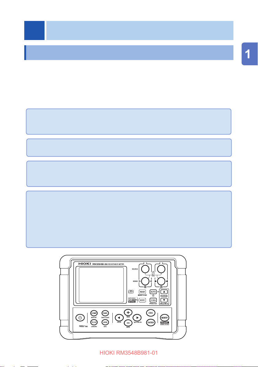
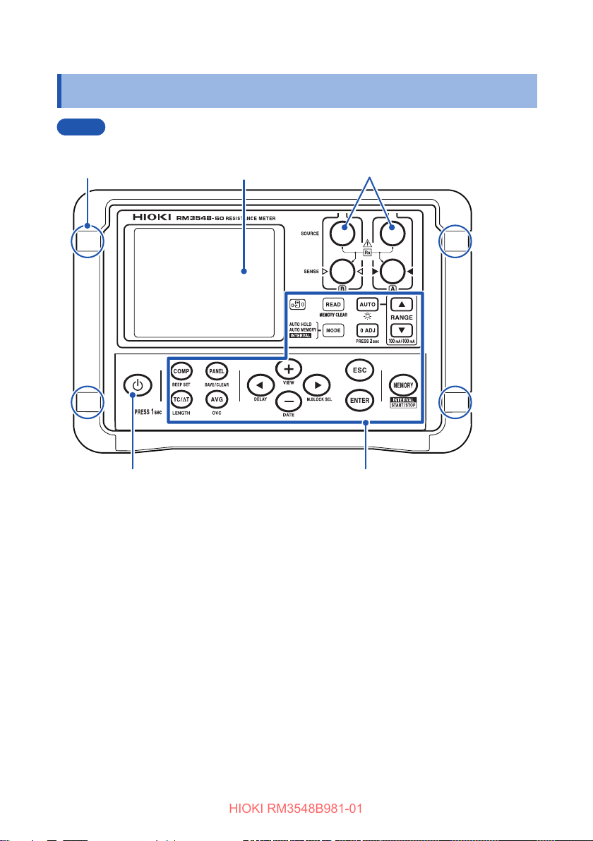
1.2 Component Names and Operation Overview
Front
Strap attachment
holes (four) (p. 34)
Turns the power on/o. (p. 37)
Display (p. 23)
Measurement
terminals (p. 35)
Operation keys (p. 18)[POWER] key
16
Page 24
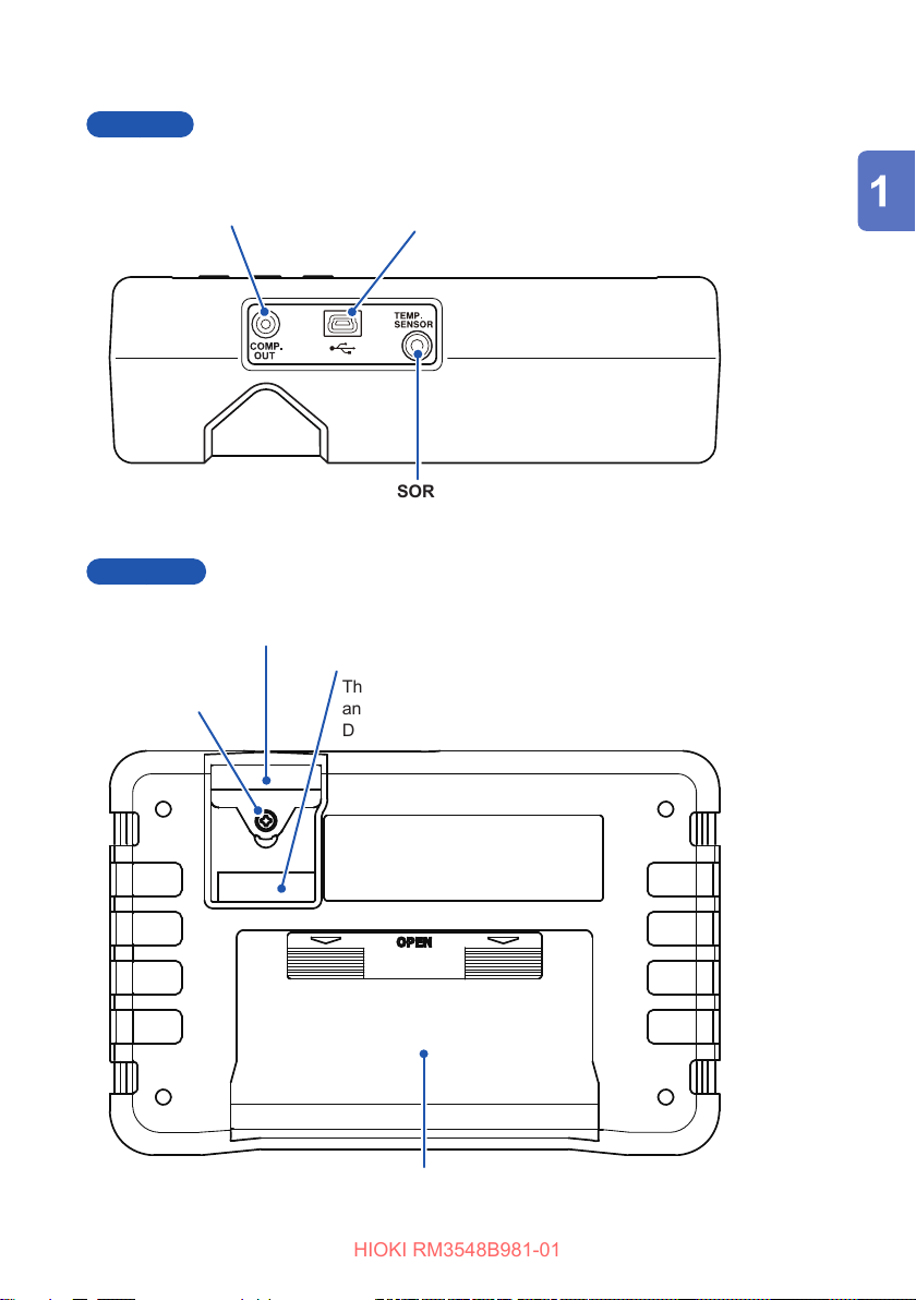
Top view
HIOKI RM3548B981-01
COMP. OUT terminal
Connect an optional L2105 LED Comparator
Attachment. (p. 72)
TEMP.SENSOR terminal
Connect the included Z2002 Temperature Sensor. (p. 36)
Back view
Fuse cover
Contains a fuse for measurement circuit protection. (p. 135)
Serial number
Set screw
The 9-digit serial number indicates the year (rst two digits)
and themonth of manufacture (next two digits).
Do not remove this sticker as the number is important.
Component Names and Operation Overview
USB terminal
Connect a USB cable. (p. 102)
Battery cover
Contains eight LR6 Alkaline batteries or
HR6 Nickel-metal hydride batteries. (p. 30)
17
Page 25
Component Names and Operation Overview
HIOKI RM3548B981-01
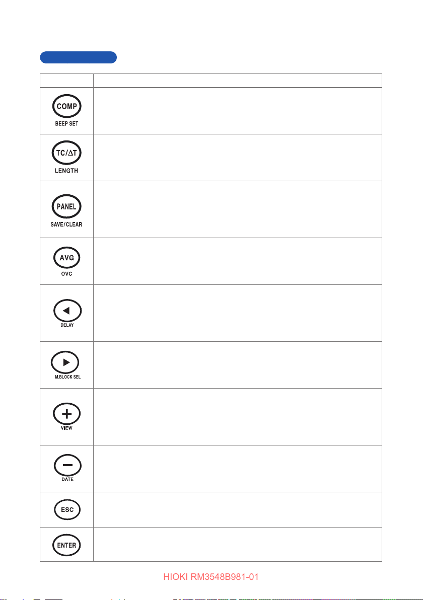
Operation keys
Key Description
[COMP] key (p. 68)
• Comparator: oFF → ON (ABS mode) → ON (REF% mode)
[BEEPSET] key (press and hold) (p. 71)
• Judgment sound: oFF → Hi → in → Lo → Hi-Lo → ALL1 → ALL2
[TC/∆T] key (p. 56) (p. 73)
• Temperature correction/conversion function: oFF → TC → ΔT
[LENGTH] key (press and hold) (p. 76)
• Length conversion function: oFF → ON
[PANEL] key (p. 81)
• Panel load: Changes the panel No. “PrSEt” initializes the measurement
conditions.
[SAVE/CLEAR] key (press and hold) (p. 80, p. 82)
• Saves and clears panels: SAvE → CLr
[AVG] key (p. 55)
• Averaging function: oFF → 2 → 5 → 10 → 20
[OVC] key (press and hold) (p. 58)
• Oset voltage compensation (OVC) function: oFF → on
[] key
• Moves to a dierent digit of the setting
[DELAY] key (press and hold) (p. 60)
• Delay function: PrSEt (factory default) → 10 ms → 30 ms → 50 ms →
100 ms → 300 ms → 500 ms → 1000 ms
[] key
• Moves to a dierent digit of the setting
[M.BLOCK SEL] key (press and hold) (p. 92)
• Selects a memory block: A → b → C → d → E → F → G → H → J → L
[+] key
• Changes values and items
[VIEW] key (press and hold) (p. 45)
• Toggles the display: Temperature → no indicator → memory number
(MEMORY No.)
[−] key
• Changes values and items
[DATE] key (press and hold) (p. 105)
• Displays the date and time conrmation screen.
[ESC] key
• Cancels the setting (when in the setting screen)
• Releases a HOLD state (if in a HOLD state)
18
[ENTER] key
Applies the setting
Page 26
Component Names and Operation Overview
HIOKI RM3548B981-01
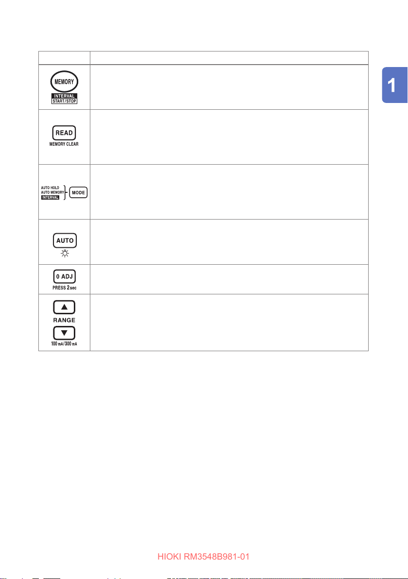
Key Description
[MEMORY] key (p. 93)
• Saves the measured values (manual memory)
[START/STOP] key (press and hold) (p. 95)
• Starts/stops interval measurement (when in interval mode)
[READ] key (p. 97)
• Displays saved measurement data
[MEMORY CLEAR] key (press and hold) (p. 98)
• Clears memory: LASt (Latest data from the selected block) → bLoC (Selected
block) → ALL (All data)
[MODE] key (p. 48, p. 94, p. 95)
• Switches memory hold mode: oFF → A.HOLD (auto-hold)
→ A.HOLD,A.MEMORY (auto-memory) → INTERVAL (interval function)
[MODE] key (press and hold) (p. 94)
• Turns on/o the wireless communications function
[AUTO] key (p. 43)
• Turns on/o the auto range: AUTO lit → not lit
[AUTO]key(pressandhold)(p. 107)
• Turns on and o the backlight
[0 ADJ] key (press and hold) (p. 50)
Zero adjustment
[RANGE] key () (p. 42)
• Measurement range:
3mΩ ↔ 30mΩ ↔ 300mΩ ↔ 3Ω ↔ 30Ω ↔ 300Ω ↔ 3kΩ ↔ 30kΩ ↔ 300kΩ ↔ 3M
[100mA/300mA] key () (press and hold)
• Switches between the measuring currents of the 300 m
range
Ω
Ω
19
Page 27
Component Names and Operation Overview
HIOKI RM3548B981-01
Operation overview
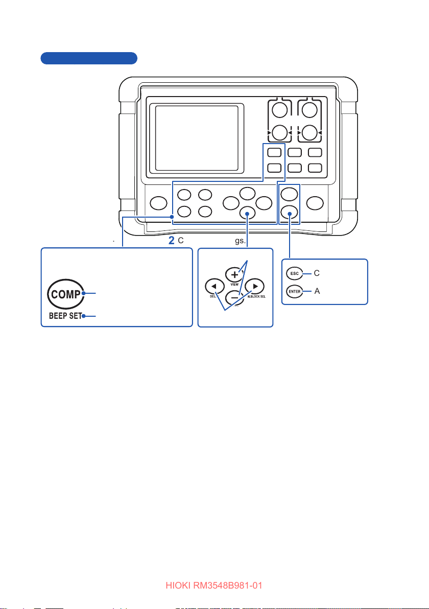
Select a function.
The function shown below each key can be
selected by pressing and holding the key.
Name of the key that turns ON
when it is pressed
Name of the key that turns ON
when it is pressed and held
Congure settings.
Changes items/values.
Moves digits.
Apply settings.
Cancel
Apply
20
Page 28
Component Names and Operation Overview
HIOKI RM3548B981-01
Power-on settings
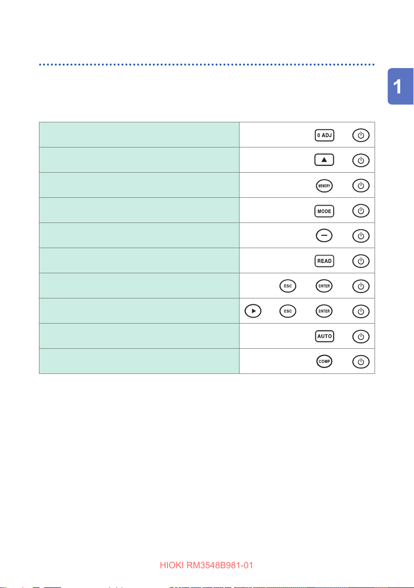
To perform one of the following settings, it is necessary to turn the power from o to
on while holding-down a particular key.
For details, see the indicated page.
Clearing zero adjustment (p. 54)
Switching to a dierent measurement current (p. 62)
Disabling auto power save (APS) (p. 38)
Changing the decimal point character or delimiter
character for a CSV le (p. 104)
Setting the date and time (p. 106)
Clearing all measurement data saved (p. 101)
Resetting the current measurement conditions (p. 108)
Resetting the system (p. 108)
Automatic backlight o setting ON/OFF (p. 107)
The HID function setting ON/OFF (p. 88)
+
+
+
+
+
+
+ +
+ + +
+
+
21
Page 29
Flow of Measurement
HIOKI RM3548B981-01
1.3 Flow of Measurement
Before using the instrument, be sure to see “Usage Notes” (p. 7).
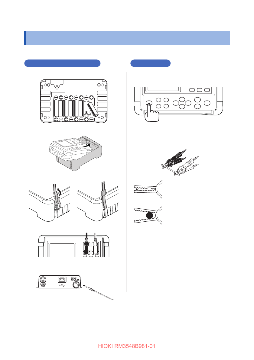
Preparing for measurement
Measurement
Load or replace the batteries. (
1
Attaching the Protector (p. 35)
2
Attach the strap. (p. 34)
3
Connect the test leads. (p. 35)
4
Connect a Z2002 Temperature
5
Sensor. (p. 36)
p. 30
)
Turnthepoweronandcongure
1
settings.* (p. 37)
Connect the test leads to the
2
measurement target. (p. 44)
Clipping a thin wire (with
the edge portion of the
jaws)
Clipping a thick wire
(with the base, nonserrated portion of the
jaws)
Read the measured value. (p. 45)
3
Remove the test leads from the
4
measurement target and turn the
powero.(p.37)
* In the following cases, perform zero adjustment:
• The display is not cleared due to thermal EMF or other factors. → The display will be changed to zero
(Accuracy is not aected by whether or not the zero adjustment is performed.)
Thermal EMF can also be canceled by using OVC. (p. 58)
• Four-terminal connection (called Kelvin connection) is dicult.
→ The residual resistance of the two-terminal connection wires will be canceled.
For zero adjustment procedures, see (p. Appx.11).
22
.
Page 30
Screen Layout
HIOKI RM3548B981-01
1.4 Screen Layout
Display (when the entire display is lit)
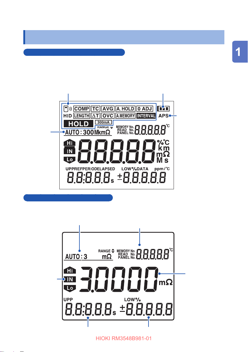
Displays measurement conditions, settings, measured values, memory numbers
(MEMORY No.), panel numbers, comparator settings, judgment results, etc. For
information on the error display, see “Error display and actions” (p. 132).
Remaining battery
Indicators(p. 25)
Range
indicator
indicator (p. 10)
APS indicator
(p. 38)
Resistance measurement screen
Comparator
judgment
result
(p. 66)
Range (p. 42)
Using the [VIEW] key to switch the indicator
display (p. 45)
(Temperature, no indicator, memory number
(MEMORY No.))
Measured
value (p. 45)
Comparator lower limit (p. 66)Comparator upper limit (p. 66)
23
Page 31
Screen Layout
HIOKI RM3548B981-01
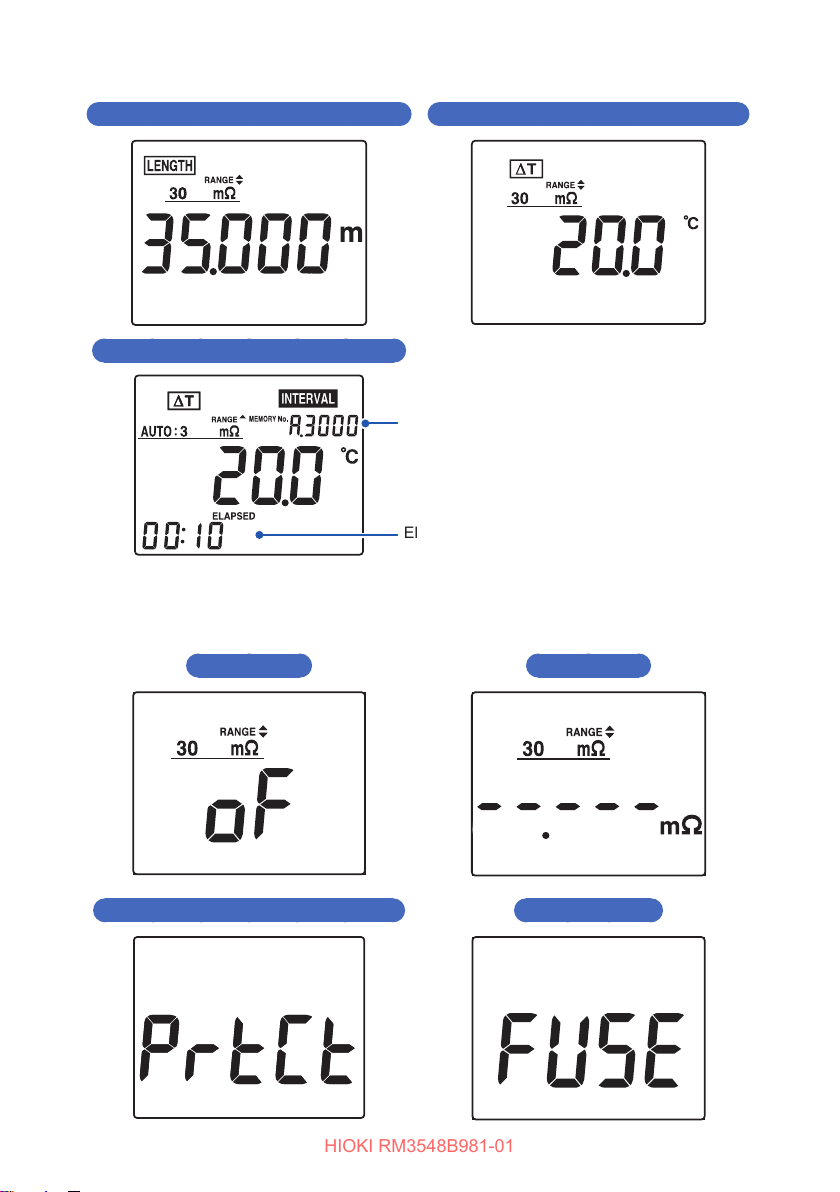
Length conversion measurement screen (p. 76)
Temperatureconversion(∆T)measurementscreen(p.73)
Interval measurement screen (p. 95)
Memory No.
Elapsed time
(The screen shows when ∆T is ON.)
Non-measured value display (see “Verifying measurement errors” (p. 46) for
details)
Out-of-range Current fault
The protection function is working Fuse blown out
24
Page 32
Screen Layout
HIOKI RM3548B981-01
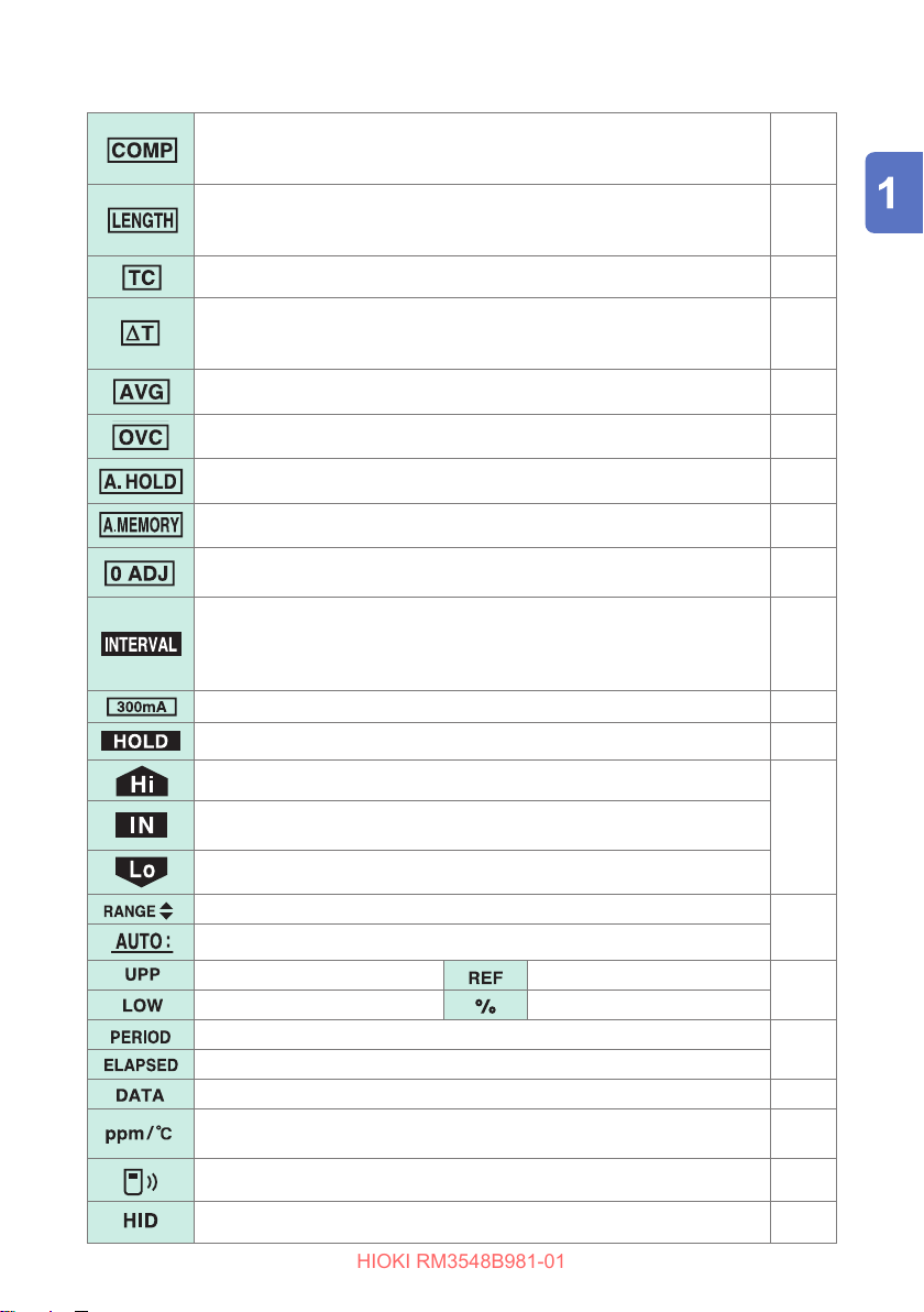
Lit: The comparator function is enabled.
Blinking: The processing of the key pressed cannot be performed
because the comparator function is enabled.
Lit: The length conversion function is enabled.
Blinking: The processing of the key pressed cannot be performed
because the length conversion function is enabled.
The temperature correction function is enabled. (p. 56)
Lit: The temperature conversion function is enabled.
Blinking: The processing of the key pressed cannot be performed
because the temperature conversion function is enabled.
The measured value averaging function is enabled. (p. 55)
The OVC function is enabled. (p. 58)
The auto-hold function is enabled. (p. 48)
The auto-memory function is enabled. (p. 94)
Lit: The zero adjustment function is enabled.
Blinking: Zero adjustment is in progress.
Lit: The interval measurement function is enabled.
Blinking: The processing of the key pressed cannot be performed
because interval measurement is being performed or the
interval measurement function is enabled.
The measurement current is set to Hi (300 mA) at the 300mΩ range. (p. 62)
The measured value is being held. (p. 48)
(p. 68)
(p. 76)
(p. 73)
(p. 50)
(p. 95)
The comparator judgment result shows “measured value > upper limit”.
The comparator judgment result shows “lower limit ≤ measured value ≤
upper limit”.
The comparator judgment result shows “measured value < lower limit”.
The range can be changed.
The auto range function is enabled.
Comparator upper limit value Comparator reference value
Comparator lower limit value Comparator allowable range
Retainable period of time (when in interval mode)
Measurement elapsed time (when in interval mode)
Number of data items that can be retained (p. 92)
Temperature coecient for temperature correction (when temperature
correction is enabled)
The wireless communication function is enabled. (p. 86)
The HID function is enabled. (p. 88)
(p. 66)
(p. 42)
(p. 66)
(p. 95)
(p. 56)
25
Page 33
Checking the Measurement Target
HIOKI RM3548B981-01
1.5 Checking the Measurement Target
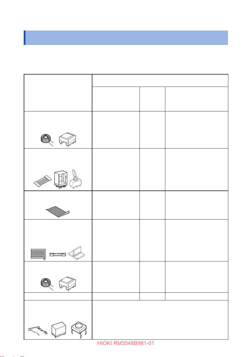
To carry out proper resistance measurement, change the measurement conditions
appropriately according to the measurement target. Before starting measurement,
use the examples recommended in the following table to congure the instrument.
Recommended settings
(Bold indicates a change from the factory default.)
Measurement target
Motor, solenoid,
choke coil, transformer, wiring
harness
For power
Contact, wiring harness,
connector, relay contact, switch
Temperature
correction (p. 56)/
Temperature
conversion (p. 73)
TC
*1
OVC
(p. 58)
OFF Lo
Measurement current at
300mΩ range (p. 62)
ON
Lo
Conductive coating material,
conductive rubber
General resistance
measurement
Fuse, resistor, heater, wiring,
welding
Temperature rise test
(Motor, choke coil, transformer)
Automobile ground wire *1
For signal
Contact, wiring harness,
connector, relay contact, switch
26
-
*1
∆T*
2
OFF Lo
ON
OFF Lo
Lo
ON Hi (300mA)
If the instrument is used to measure the resistance of a signal
contact, the contact status will be changed, because its opencircuit voltage and measurement current are both high.
To measure a signal contact, use the RM3545.
Page 34
Checking the Measurement Target
HIOKI RM3548B981-01
*1
When the measurement target signicantly depends on temperature, use the temperature
correction function.
*2
The interval measurement function allows you to save a measured value every xed interval.
(p. 95)
IMPORTANT
If a measurement fails with the PrSEt (preset) delay setting, set a long enough
delay time. (p. 60)
27
Page 35

Checking the Measurement Target
HIOKI RM3548B981-01
28
Page 36
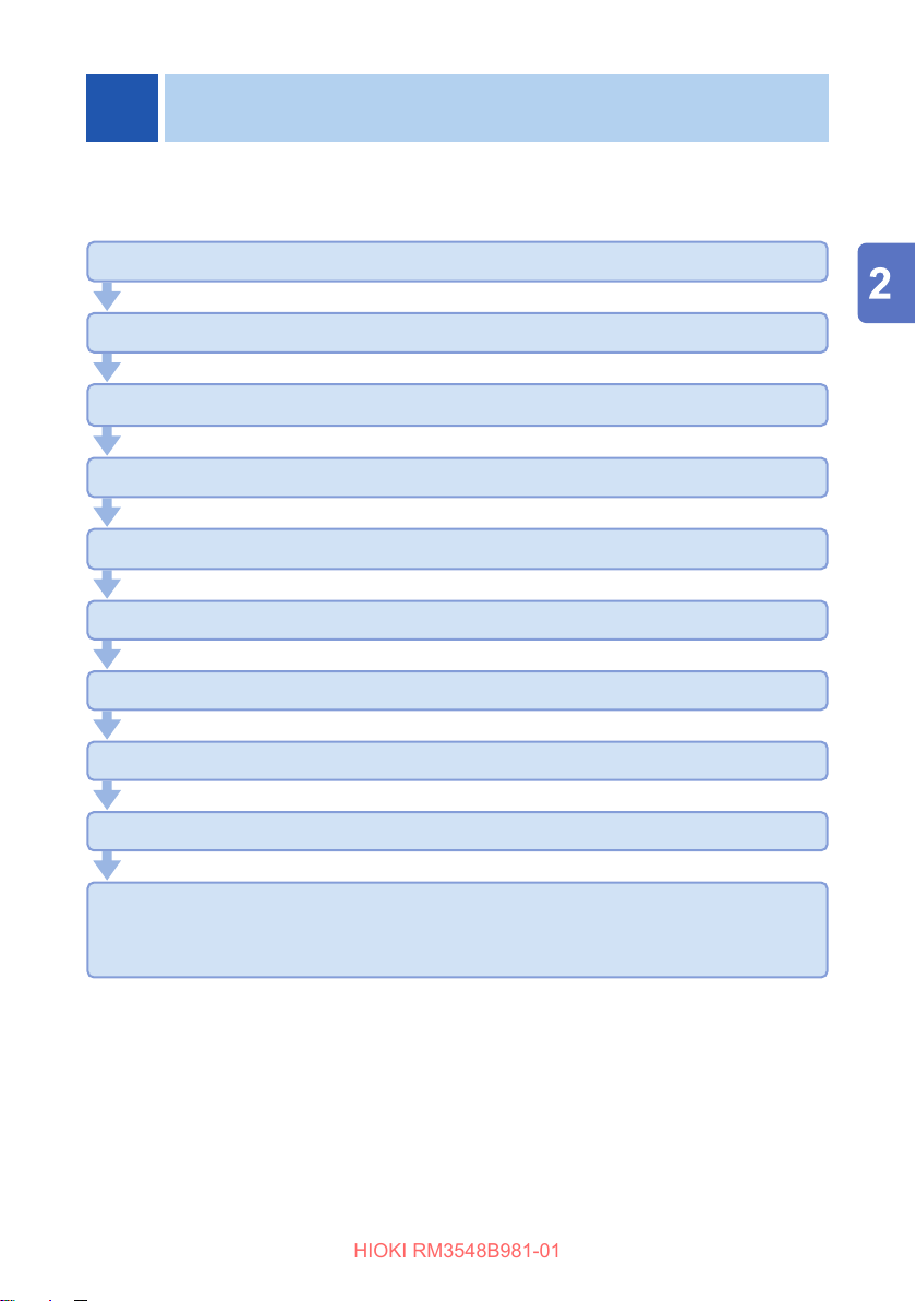
2
HIOKI RM3548B981-01
Before using the instrument, be sure to see “Usage Notes” (p. 7).
Loading or replacing the batteries (p. 30)
InstallingtheZ3210WirelessAdapter(optionalequipment)(p. 32)
AttachingtheZ5041Protector(p. 33)
Attaching the strap (p. 34)
Connecting the test leads (p. 35)
Connecting a Z2002 Temperature Sensor (p. 36)
Inspecting the instrument (p. 39)
Preparing for Measurement
Turning the power on (p. 37)
Measurement
Turningthepowero(p.37)
If the instrument is not operated for a while, it will turn o automatically. (APS
function) (p. 38)
29
Page 37
Loading or Replacing the Batteries
HIOKI RM3548B981-01
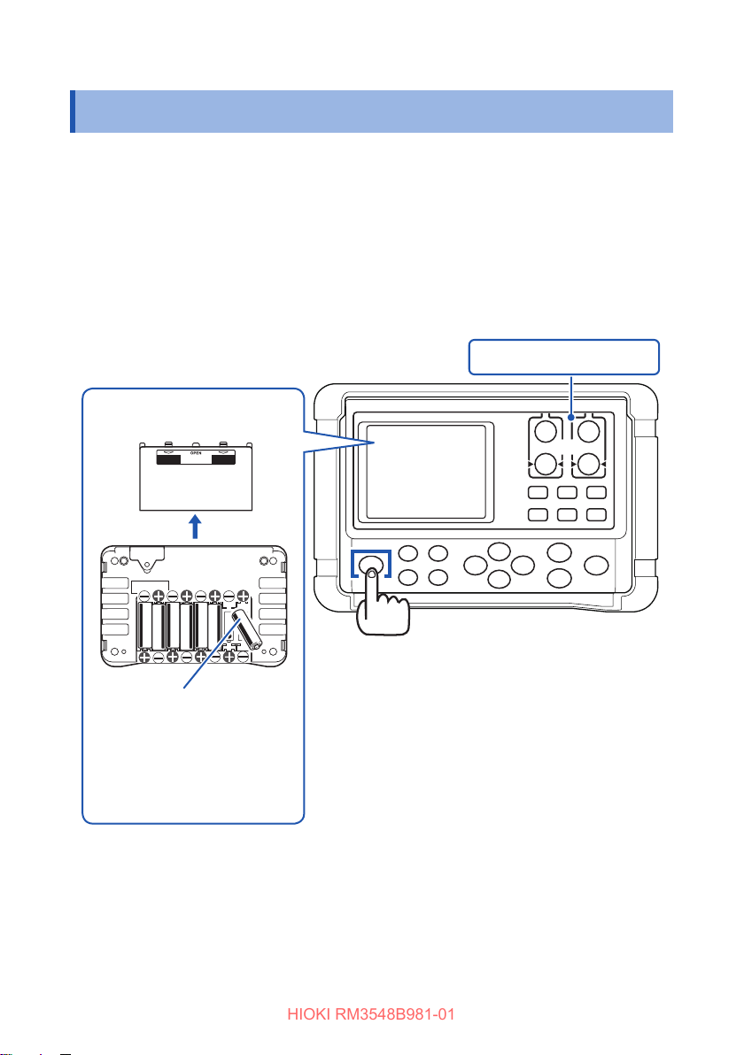
2.1 Loading or Replacing the Batteries
Before using the instrument for the rst time, insert eight LR6 Alkaline batteries or
HR6 Nickel-metal hydride batteries. Before measurement, check that the instrument
has sucient remaining battery power. If the remaining battery level is low, replace
the batteries. See the battery indicator to check the remaining battery level. (p. 10)
Preparations
• Fresh LR6 Alkaline battery ×8 or
fully charged HR6 Nickel-metal hydride battery ×8
Remove the test leads.
Remove the battery cover on
the back of the instrument.
Insert eight batteries (LR6
or HR6).
(Be careful of their polarity.)
Reattach the battery
cover on the back of the
instrument.
30
Turn the power o.
(Press the [POWER] key to turn the entire
display o.)
Page 38
Loading or Replacing the Batteries
HIOKI RM3548B981-01
Nickel-metal hydride batteries
CAUTION
When using the instrument, insert eight LR6 Alkaline batteries or four fully
charged HR6 Nickel-metal hydride batteries.
The instrument powered by nickel-metal hydride batteries will indicate an inaccurate
remaining-battery level; however, it can be used without any other trouble even with
such batteries inserted.
See the continuous operating time below (for reference purposes only).
When eight LR6 Alkaline batteries or eight HR6 Nickel-metal hydride batteries (1900 mAh
capacity) are used
Approx. 10 hours
When making measurements using the 3 mΩ range for 1 s per 10 s, backlight o
Visit an FAQ page on Hioki’s global website for more information about nickel-metal
hydride batteries that Hioki has guaranteed to work.
31
Page 39
Connecting the Z3210 Wireless Adapter (Option)
HIOKI RM3548B981-01
2.2 Connecting the Z3210 Wireless Adapter (Option)
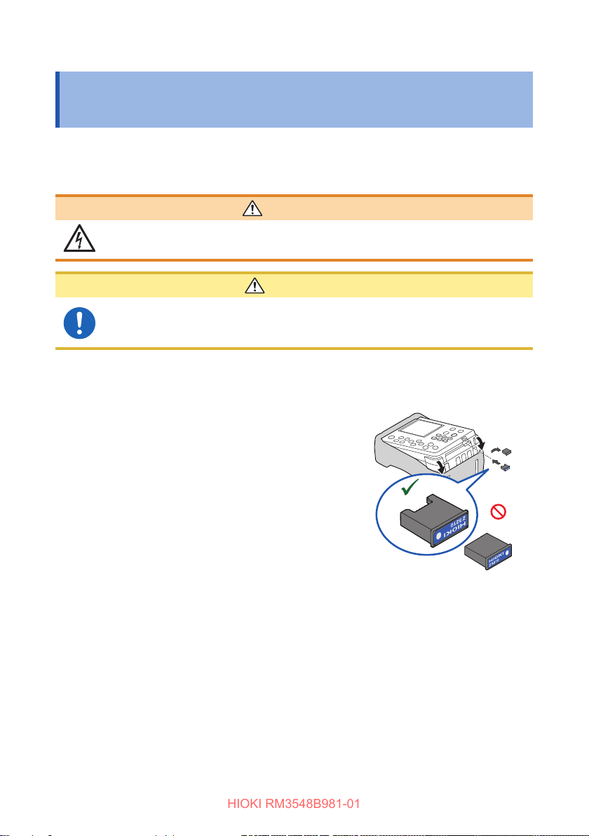
Installing the Z3210 Wireless Adapter (option) in the instrument lets you use the
wireless communications function.
See “7.1 Communicating With a Mobile Device” (p. 84)
WARNING
Turnotheinstrumentandremovethetestlead.
Failure to do so could cause an electric shock.
CAUTION
Before handling the Z3210, eliminate static electricity from your body
by touching any metallic part, such as a doorknob.
Failure to do so could cause static electricity to damage the Z3210.
Turnotheinstrumentandremovethetest
1
lead.
Remove the Z5041 Protector while pressing
2
down it as shown.
Removetheprotectivecapwithaathead
3
screw driver.
Insert the Z3210, observing the correct
4
orientation, as far as it will go.
Attach the Protector.
5
• Store the removed protective cap.
• When removing the Z3210, install the protective cap.
32
OK
NO
Page 40
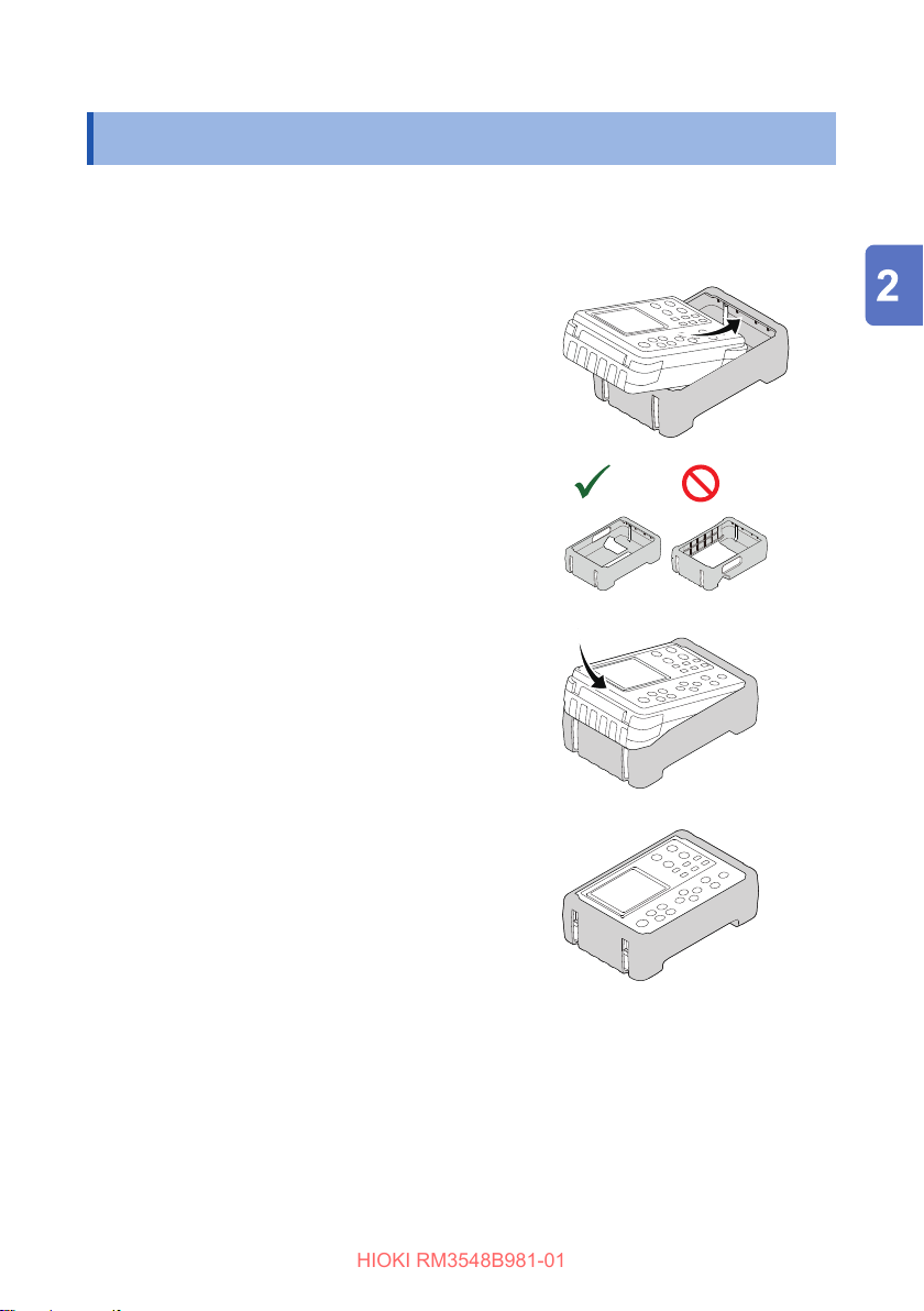
Attaching the Z5041 Protector
NO
HIOKI RM3548B981-01
2.3 Attaching the Z5041 Protector
If the Z5041 Protector has been removed from the instrument,attach it by following
the instruction below.
Turnotheinstrumentandremovethetest
1
lead.
Insert the instrument into the Z5041
2
Protector.
Observe the proper orientation.
Push the instrument into the Protector in
3
the direction of the arrow.
OK
NO
33
Page 41
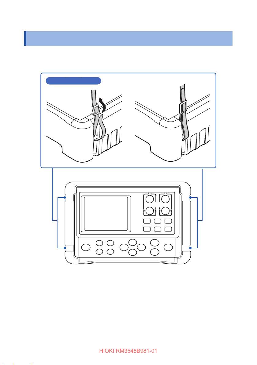
Attaching the Strap
HIOKI RM3548B981-01
2.4 Attaching the Strap
Attaching the strap to the instrument allows you to use it with the strap around your
neck. Follow the procedure below to attach the strap.
Attaching the strap
スススススススススススス
34
Page 42
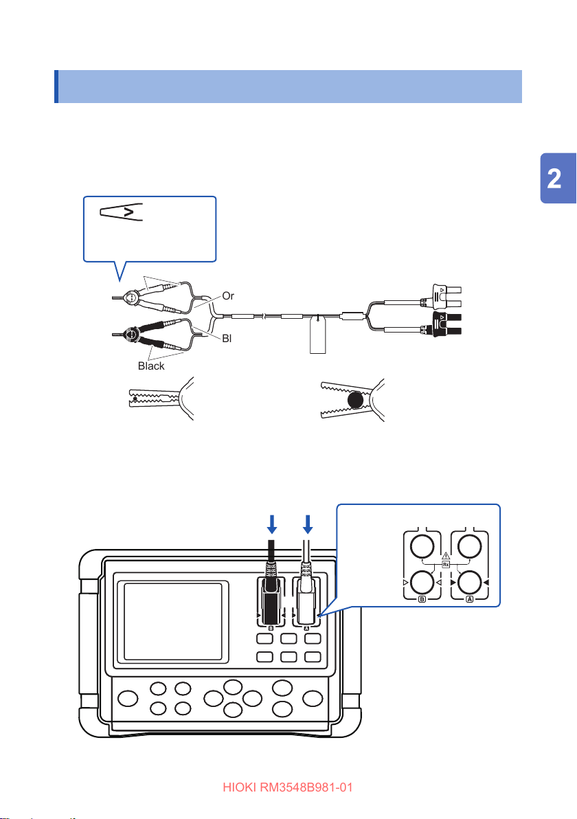
Connecting the Test Leads
HIOKI RM3548B981-01
2.5 Connecting the Test Leads
Use the included L2107 Clip Type Leads or select from our wide range of optional
test leads. For more information on the lead options, see “Options” (p. 3).
Test leads
(Example: L2107 Clip Type Leads)
The V mark indicates a
SENSE lead.
SENSE
SOURCE
SOURCE
SENSE
Red
Orange
Blue
Black
Red
SENSE
SOURCE
SENSE
SOURCE
Black
To clip a thin wire
(Use the edge portion of the jaws.)
Connect the test leads to the instrument.
Connect the four terminals: SOURCE (A and B) and SENSE (A and B).
To clip a thick wire
(Use the base, non-serrated portion of the jaws.)
Black Red
SOURCE
SENSE
RedBlack
35
Page 43
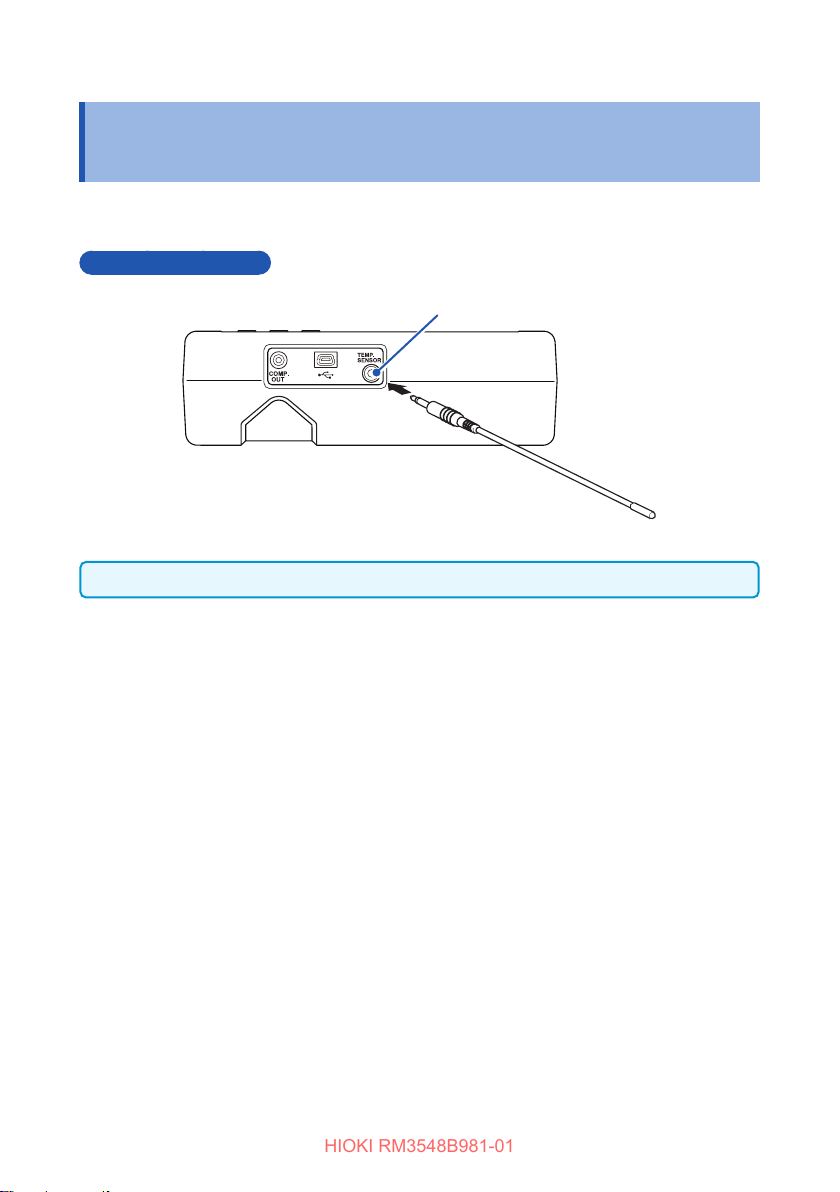
Connecting the Z2002 Temperature Sensor (When Using TC or ΔT)
HIOKI RM3548B981-01
2.6 Connecting the Z2002 Temperature Sensor (When Using TC or ΔT)
Connect the Z2002 Temperature Sensor to the TEMP.SENSOR terminal.
Connection method
TEMP.SENSOR terminal
Fully insert the jack.
36
Page 44
Turning the Power On/O
HIOKI RM3548B981-01
2.7 TurningthePowerOn/O
Turning the power on
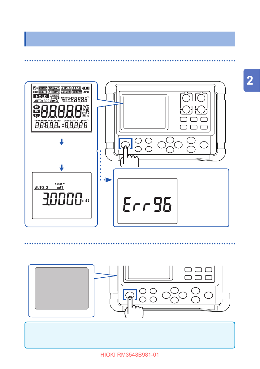
Press the [POWER] key to turn the power on. Hold the key down until the entire
display turns on.
Entire display lit
A self-test is started.
The model name and version
number are displayed during
the self-test.
If an error occurs during the self-test
[POWER] key
Measurement screen
Turningthepowero
Press the [POWER] key to turn the power o. Hold the key down until the entire
display turns o.
Entire display o
IMPORTANT
When the instrument is turned on again, it starts up with the previous state used
immediately before turning it o.
The error is
displayed. (p. 132)
[POWER] key
37
Page 45
Turning the Power On/O
HIOKI RM3548B981-01
Automaticpowerowithautopowersave(APS)
When the instrument is not being used, the APS function automatically turns it o to
reduce battery consumption.
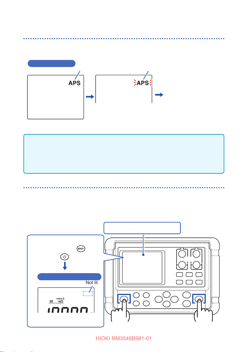
APS function ON
Lit Blinking
If no key is operated for 10 minutes
or the instrument is in a measurement
error state continuously, the APS
indicator starts blinking.
Then, when a specic
time elapses after the start
of blinking, the instrument
automatically turns o.
IMPORTANT
• During an interval measurement, the APS function automatically turns OFF. When
the interval measurement ends, the APS function automatically turns ON.
• When the USB is connected, the APS function automatically turns OFF. When the
USB is disconnected, the APS function automatically turns ON.
Disabling auto power save (APS)
To disable the APS function, press the [POWER] key while holding the [MEMORY]
key down when the power is o.
The setting of the APS function is not saved. When the instrument is turned on again,
the APS function is enabled again.
When the power is o, while
holding down the
press the
The APS function is OFF
(The power is on and the
APS indicator turns o.)
38
key.
key,
Not lit
Turn the power o (if it is on).
[POWER] key
[MEMORY] key
Page 46
Pre-measurement Inspection
HIOKI RM3548B981-01
2.8 Pre-measurement Inspection
Before using the instrument, inspect it to verify that no damage has occurred during
storage or transportation and it operates normally. If you nd any damage, contact
your authorized Hioki distributor or reseller.
Instrument and peripheral checking
Inspection item Action
Is there any damage or a crack in the
instrument? Are the internal circuits exposed?
Is there any dust or contamination, such as
pieces of metal, on any terminals?
Is the test lead coating broken or is the metal
exposed?
Power-on checking
Inspection item Action
Is the remaining battery power sucient? The
Is anything missing from the screen? Turn the power on to make sure that the entire
When you turn the power on, does the entire
display turn on and then the model name and
a measurement screen appear on the screen?
If any damage is found, do not use it. Return it
for repair.
If dust or contamination is adhered to a
terminal, clean the terminal with a swab or the
like.
If the coating of a test lead is broken, the
measured value may become unstable or
have an error.
Replace the damaged test lead.
indicator at the upper right of the
display indicates the current status. If the
indicator changes to , the remaining
battery level is low. Replace the batteries as
early as possible. If the battery level becomes
too low to continue with measurement, the
starts blinking. Replace the batteries.
display turns on. (p. 23)
If there is anything missing, return the
instrument for repair.
If the screen does not behave like this, the
instrument may be damaged internally. Return
it for repair.
See: “11.1 Troubleshooting” (p. 126)
“Error display and actions” (p. 132)
39
Page 47

Pre-measurement Inspection
HIOKI RM3548B981-01
40
Page 48
3
HIOKI RM3548B981-01
Before measurement, be sure to see “Measurement precautions” (p. 12).
This chapter describes the basic operations for using the instrument.
• “3.1 Setting the Measurement Range” (p. 42)
• “3.2 Connecting the Test Leads to the Measurement Target” (p. 44)
• “3.3 Reading the Measured Value” (p. 45)
For information on how to customize measurement conditions, see “Customizing
Measurement Conditions” (p. 49).
Basic Measurement
41
Page 49
Setting the Measurement Range
HIOKI RM3548B981-01
3.1 Setting the Measurement Range
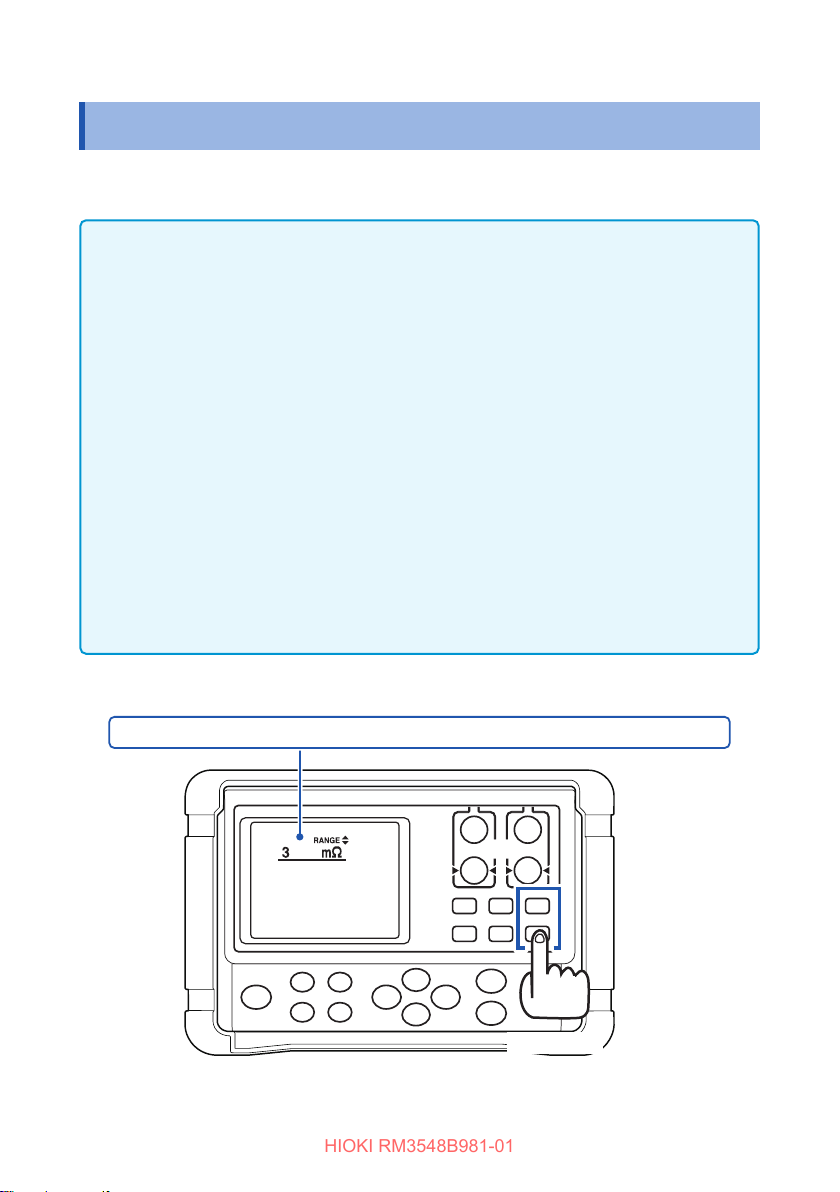
Select a measurement range. Automatic range selection (the auto range) is also
available.
IMPORTANT
When the auto range is used or the measurement range is set to 30mΩ or less, a
maximum current of 1 A may constantly ow through the measurement target, and
a maximum power of approximately 2 W may be applied*.
If there are any of the following concerns, depending on the level of the
measurement current, select a range using a lower measurement current.
• The measurement target may melt (such as a fuse or inator).
• The measurement target may heat up, causing a change in resistance.
• The measurement target may be magnetized, causing a change in inductance.
Within each of the measurement ranges, the power for the measurement target can
be expressed by “resistance × (measurement current)
is deviated, the power may reach the value of “open-circuit voltage × measurement
current” at maximum.
Before connecting the measurement target, be sure to check the measurement
range.
* At the moment of connecting the measurement target, a maximum inrush current
of 5 A ows.
(Convergence time: Approximately 1 ms for pure resistance)
2
”. If the measurement range
Using the manual range
3mΩ ↔ 30mΩ ↔ 300mΩ ↔ 3Ω ↔ 30Ω ↔ 300Ω ↔ 3kΩ ↔ 30kΩ ↔ 300kΩ ↔ 3M
42
Ω
[][] key
Page 50
Setting the Measurement Range
HIOKI RM3548B981-01
Using the auto range
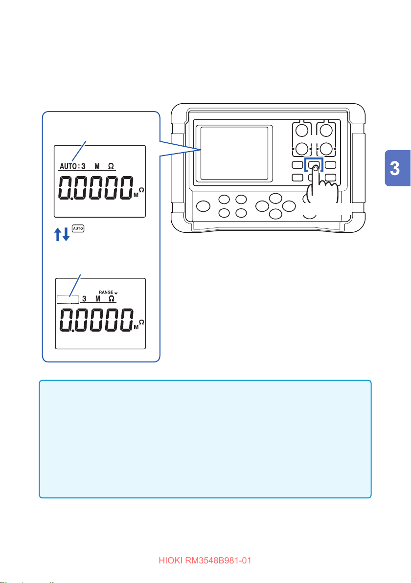
Use the [AUTO] key to switch to the auto range. (The default setting is AUTO.)
When the instrument is in the auto range mode, AUTO is lit.
(The auto range)
AUTO lit
[AUTO] key
Toggles the auto
range ON and OFF.
(The manual range)
Not lit
IMPORTANT
• When the range is manually changed in the auto range mode, the auto range is
automatically disabled and the manual range is enabled.
• If the comparator function is turned ON, the range is xed and cannot be
changed. To change the range, turn the comparator function OFF or change the
range in the comparator setting.
• Depending on the measurement target, the auto range may become unstable. In
such a case, specify the range manually or increase the delay time. (p. 60)
For the measurement accuracy of each range, see “(2) Resistance measurement
specications” (p. 112).
43
Page 51
Connecting the Test Leads to the Measurement Target
HIOKI RM3548B981-01
3.2 Connecting the Test Leads to the Measurement Target
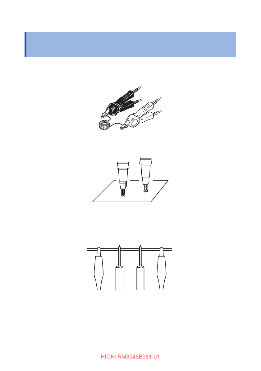
Example: Using the L2107
Example: Using the 9772
Example: Using the 9453
The SENSE terminals should be located inside the SOURCE terminals.
44
(Press)
SOURCE A SOURCE B
SENSE A SENSE B
Page 52
Reading the Measured Value
HIOKI RM3548B981-01
3.3 Reading the Measured Value
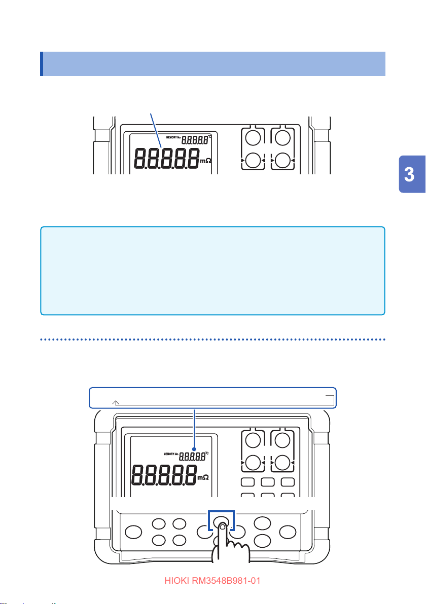
The instrument displays a resistance value.
If a non-resistance value is displayed, see “Verifying measurement errors” (p. 46).
To convert the measured resistance value, see the following pages:
• “5.2 Performing Temperature Rise Test (Temperature Conversion Function (∆T))”
(p. 73)
• “5.3 Measuring the Length of a Conductor (Length Conversion Function)” (p. 76)
IMPORTANT
If the measured value has a negative sign (-), check the following:
• The SOURCE and SENSE lead connections are reversed.
→ Connect the leads correctly.
• After zero adjustment for a two-terminal measurement, the contact resistance
has decreased.
→ Perform zero adjustment again.
Switching the display
Press and hold the [+] (VIEW) key to switch the type of information displayed on the
upper right of the screen. (Temperature, no indicator, memory number (MEMORY No.))
The type of information displayed during measurements can be selected.
Temperature → no indicator → memory number (MEMORY No.)
Press the [+] (VIEW) key to display a selection screen.
Press and hold
45
Page 53
Reading the Measured Value
HIOKI RM3548B981-01
Verifying measurement errors
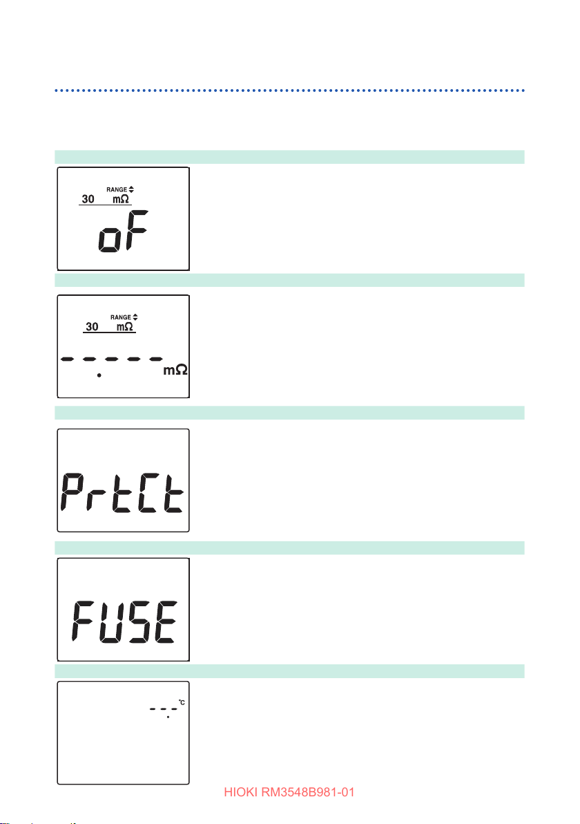
If a measurement is not performed correctly, the measurement error is displayed on
the screen.
Out-of-range*
Current fault or not measured yet
The protection function is working
Fuse blown out
1
Indicates that the measurement or display range has been
exceeded.
If oF is displayed, the comparator judgment is “Hi”, and if -oF is
displayed, the comparator judgment is “Lo”.
In the same manner, oF is displayed when the temperature
exceeds the measurement range during temperature
measurement.
This screen is displayed in the following two cases.
If “-----” is displayed, comparator judgment is not performed.
1. Measurement current fault*
Current cannot be supplied to the SOURCE A or SOURCE B
terminals.
2. No measurement has been performed after changing a
measurement condition.
If an overvoltage is applied to the measurement terminals of
the instrument, the protection function of the internal circuit
is activated, and the backlight turns red. If an overvoltage is
accidentally applied, remove the test leads from the measurement
target immediately. Measurement cannot be performed while the
protection function is activated. In order to cancel the protection
function, contact test lead A (red) to B (black) or turn the power o
and on. The red backlight turns o when the protection function is
deactivated.
2
Z2002 Temperature Sensor not connected
46
Each SOURCE terminal of the instrument is equipped with a
fuse to protect against overvoltage input. If an overvoltage is
accidentally applied and a fuse is blown, replace the fuse. (p. 135)
Temperature cannot be measured as the Z2002 Temperature
Sensor is not connected. When TC or ∆T is not used, it is not
necessary to connect the Z2002 Temperature Sensor. If the
temperature is not to be displayed, switch the display by pressing
the [+] (VIEW) key.
Page 54
Reading the Measured Value
HIOKI RM3548B981-01
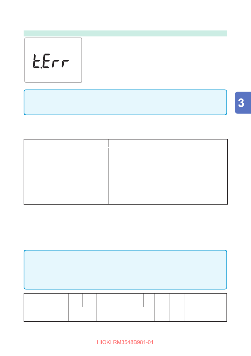
Temperature calculation error
The Z2002 Temperature Sensor is not connected even when TC
or ∆T is ON, or oF is displayed for the temperature.
Check the connection of the Z2002 Temperature Sensor.
IMPORTANT
If the measurement target is connected to the SOURCE terminal, but a SENSE
terminal has a bad contact, the displayed measured value may be unstable.
*1 Out-of-range detection function
Examples detected as out-of-range
Out-of-range detection Measurement examples
The measurement range is exceeded. 40m
The relative display (% display) of a
measured value exceeds the display
range (999.99%).
The A/D converter input range is
exceeded during a measurement.
The calculation result cannot be
displayed.
is measured in the 30mΩ range.
Ω
(+2400%) is measured with a reference value of
500
Ω
20Ω.
Such an error occurs, for example, if a high resistance
is measured in an environment with external noise.
The calculation result for the length conversion
function exceeds 999.99 km.
*2 Current fault detection function
Current fault examples
• The SOURCE A or SOURCE B probe is open.
• The measurement target has a broken wire (open-circuit work).
• The SOURCE A or SOURCE B wiring has a broken wire or a bad connection.
IMPORTANT
A wiring resistance exceeding the following value in each range causes a current
fault, making the measurement impossible. In the 1 A measurement current range,
reduce the resistance of the wiring and contact between the measurement target
and test leads.
Range [Ω] 3m 30m 300m
Wiring and contact
resistance [
The values listed above, which is for reference, indicate resistance values between the
SOURCE B and SOURCE A, not including the measurement target.
300m
(300mA)
]
Ω
0.5 3 10 100 2k 800 2k
(100mA)
3 30 300 3k 30k to 3M
47
Page 55
Reading the Measured Value
HIOKI RM3548B981-01
Holding a measured value
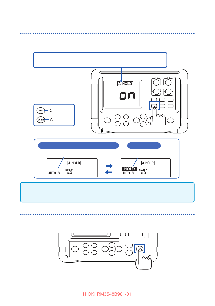
The auto-hold function helps to verify a measured value. When the measured value
becomes stable, the value is automatically held.
oFF → Auto-hold (A.HOLD) → Auto-memory (A.HOLD, A.MEMORY)
→ Interval (INTERVAL) → oFF
Cancel
Apply
[MODE] key
During measurement (during release from HOLD)
Not lit
Release the test leads from the measurement target and contact the leads to the target again.
The HOLD is released. You can also release the HOLD by changing the range or pressing the
[ESC] key.
During HOLD
Lit
Memorizing a measured value
The memory function helps to verify a measured value later.
It saves the displayed measured value.
[MEMORY] key
For more details about the memory function, see “8.1 Saving Data at Specied Time
(Manual Memory)” (p. 93).
48
Page 56
Customizing Measurement
HIOKI RM3548B981-01
4
Conditions
Before measurement, be sure to see “Measurement precautions” (p. 12).
This chapter describes the functions useful to perform more sophisticated and
accurate measurement.
• “4.1 Using Zero Adjustment” (p. 50)
• “4.2 Stabilizing Measured Values (Averaging Function)” (p. 55)
• “4.3 Compensating for Thermal Eects (Temperature Correction (TC))” (p. 56)
• “4.4 Compensating for Thermal EMF Oset (Oset Voltage Compensation
Function: OVC Function)” (p. 58)
• “4.5 Setting the Delay Time for Measurement (Delay Function)” (p. 60)
• “4.6 Switching the Measurement Current (In the 300m
Range)” (p. 62)
Ω
49
Page 57

Using Zero Adjustment
HIOKI RM3548B981-01
4.1 Using Zero Adjustment
In the following cases, perform zero adjustment:
(A resistance of up to ±3%f.s. can be canceled for any range.)
• The measurement value is not cleared due to thermal EMF or other factors.
→ The measurement value will be changed to zero.
Accuracy is not aected by whether or not the zero adjustment is performed.
The thermal EMF can also be canceled by using OVC. (p. 58)
• Four-terminal connection (called Kelvin connection) is dicult.
→ The residual resistance of the two-terminal connection wires will be canceled.
(p. Appx.24)
For instructions on how to perform zero adjustment correctly, see “Appx. 7 Zero
Adjustment” (p. Appx.11).
Before zero adjustment
IMPORTANT
• When the ambient temperature changes or the test leads are replaced after zero
adjustment, perform zero adjustment again.
However, there are no zero adjustment boards dedicated for the L2140, L2141,
or L2142. Use the L2107 Clip Type Leads, which come standard, to perform
zero adjustment, then replace them with leads to be used before making
measurements.
• Perform zero adjustment for each range used. In the manual range mode, only
the current range is adjusted to zero. In the auto range mode, all ranges are
adjusted to zero.
• Zero adjustment values are held internally even if the instrument is power o, but
they are not saved in the panel.
• When the oset voltage compensation (OVC) function is turned from ON to OFF
or from OFF to ON, the zero adjustment is cleared. Perform zero adjustment
again.
• When the measurement current is changed from Lo to Hi or from Hi to Lo, the
zero adjustment is cleared. Perform zero adjustment again.
• When a lower resistance is measured after zero adjustment, the measured value
will be negative.
Example: 2m
is connected in the 300mΩ range and then zero adjustment is
Ω
performed.
→If 1m
is measured, -1mΩ is displayed.
Ω
50
Page 58
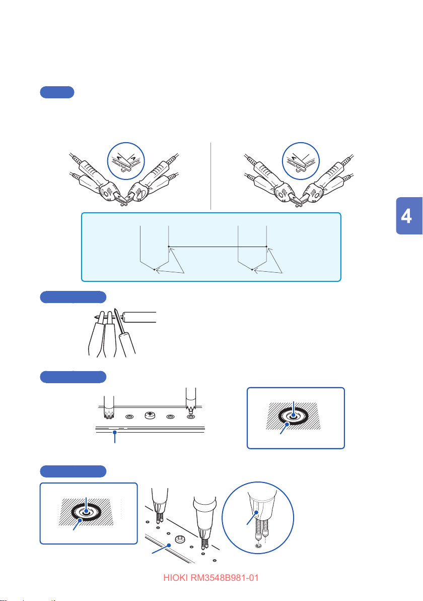
Performing zero adjustment
HIOKI RM3548B981-01
Short the test leads.
1
L2107
Using Zero Adjustment
Correct
Align the V symbols on the clips.
SENSE
SOURCE
Red Black
9453 (Option)
9465 (Option)
Incorrect
SENSE
SOURCE
Connect Connect
Perform zero adjustment while the alligator clips are
located outside and the lead bar is located inside.
SENSE
SOURCE SENSE
Red Black
SOURCE-BSENSE-A SENSE-B SOURCE-A
Contact to SENSE terminal
SOURCE
9454 Zero Adjustment Board (Option)
9772 (Option)
Contact to SENSE terminal
Contact to SOURCE terminal
9454 or Z5038 Zero
Adjustment Board (Option)
Contact to SOURCE terminal
For the pin on the
SENSE side, a line is
attached to the base
section.
Line
When performing zero
adjustment, be sure
that this line faces the
same direction on all of
the pins.
51
Page 59
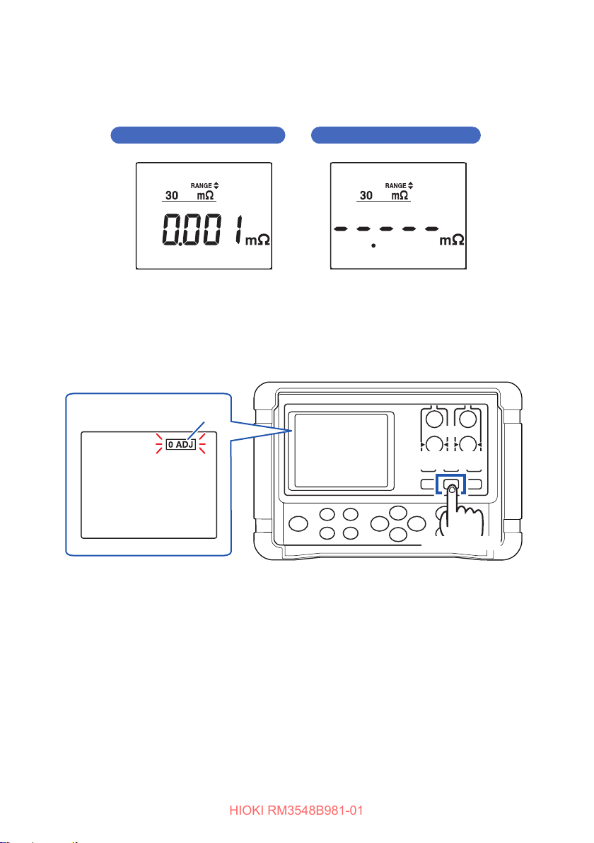
Using Zero Adjustment
HIOKI RM3548B981-01
Conrmthatthemeasuredvalueiswithin±3%f.s.
2
If no measured value is displayed, make sure that the test leads are connected
correctly.
If the connection is correct If the connection is wrong
Press and hold the [0 ADJ] key to perform zero adjustment.
3
If it is dicult to press the key as the Zero Adjustment Board is used, press
the [0 ADJ] key before shorting the measurement lead. Zero adjustment is
automatically performed after the measured value is stabilized.
(Zero adjustment in
progress)
Blinking
[0 ADJ] key
Press and hold
52
Page 60
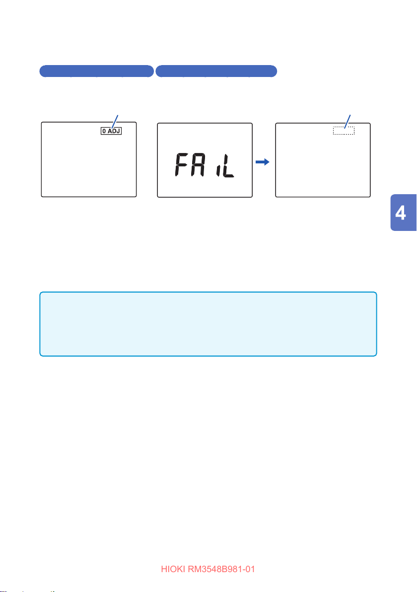
Using Zero Adjustment
HIOKI RM3548B981-01
After zero adjustment
4
Zero adjustment has succeeded
The buzzer sounds and the
measurement screen appears.
Indicator ON Indicator OFF
Zero adjustment has failed
The buzzer sounds and [FAIL] appears.
Then, the measurement screen appears.
Zero adjustment failed
When zero adjustment cannot be performed, the measured value before zero
adjustment already exceeds ±3% of the full scale of each range or the instrument is in
a measurement error state. Perform zero adjustment with the correct wire connection
again. If the resistance is too high (e.g., due to a self-made cable), zero adjustment
cannot be performed. In such a case, try to minimize the wiring resistance. (p. 47)
IMPORTANT
• If zero adjustment fails in the auto range mode, the zero adjustment is cleared for
all ranges.
• If zero adjustment fails in the manual range mode, the zero adjustment is cleared
for the current range.
53
Page 61
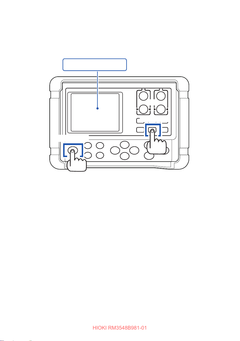
Using Zero Adjustment
HIOKI RM3548B981-01
Clearing zero adjustment
When the power is o, while holding the [0 ADJ] key, press the [POWER] key to
clear the zero adjustment for all ranges.
Turn the power o (if it is on).
[0 ADJ] key
[POWER] key
54
Page 62
Stabilizing Measured Values (Averaging Function)
HIOKI RM3548B981-01
4.2 Stabilizing Measured Values (Averaging Function)
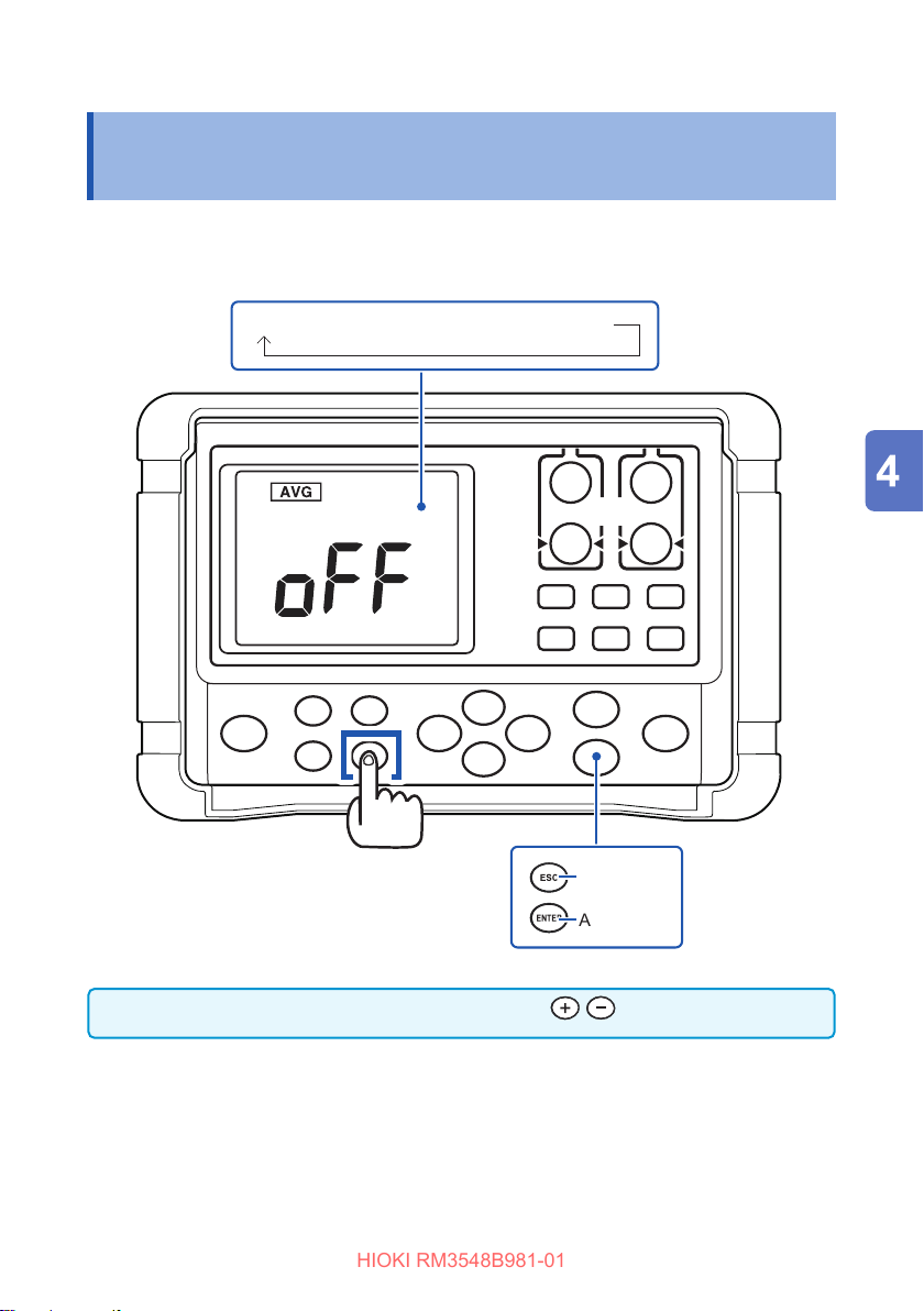
This function averages the measurement values in order to display a single value. It
helps to stabilize uctuations in the measured values.
oFF (factory default) → 2 → 5 → 10 → 20
The averaging frequency can also be changed with .
Changes the
averaging frequency.
([AVG] key)
Cancel
Apply
55
Page 63

Compensating for Thermal Eects (Temperature Correction (TC))
HIOKI RM3548B981-01
4.3 CompensatingforThermalEects
(Temperature Correction (TC))
This function converts a measured resistance value, based on the reference
temperature, to display the converted value. For the principles of temperature
correction, see “Appx. 4 Temperature Correction Function (TC)” (p. Appx.4).
56
Page 64
Compensating for Thermal Eects (Temperature Correction (TC))
HIOKI RM3548B981-01
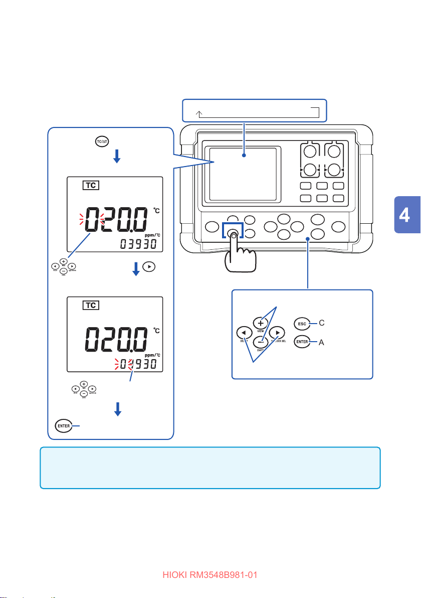
To perform temperature correction, connect the Z2002 Temperature Sensor to the
TEMP.SENSOR terminal on the side of the instrument. Before connecting the sensor,
be sure to read “2.6 Connecting the Z2002 Temperature Sensor (When Using TC or
T)” (p. 36).
Δ
oFF (factory default) → TC → ∆T
Use the key to select TC.
(Reference temperature setting)
Reference
temperature
setting
(Temperature coecient setting)
[TC/∆T] key
Changes values.
Apply and move to the
measurement screen.
IMPORTANT
If “t.Err” is displayed, the Z2002 Temperature Sensor may not be connected, or oF is
displayed for the temperature. Check the connection of the Z2002 Temperature Sensor.
Cancel
Apply
Moves digits.
Temperature
coecient setting
57
Page 65
Compensating for Thermal EMF Oset (Oset Voltage Compensation Function: OVC Function)
HIOKI RM3548B981-01
4.4 CompensatingforThermalEMFOset
(OsetVoltageCompensationFunction:
OVC Function)
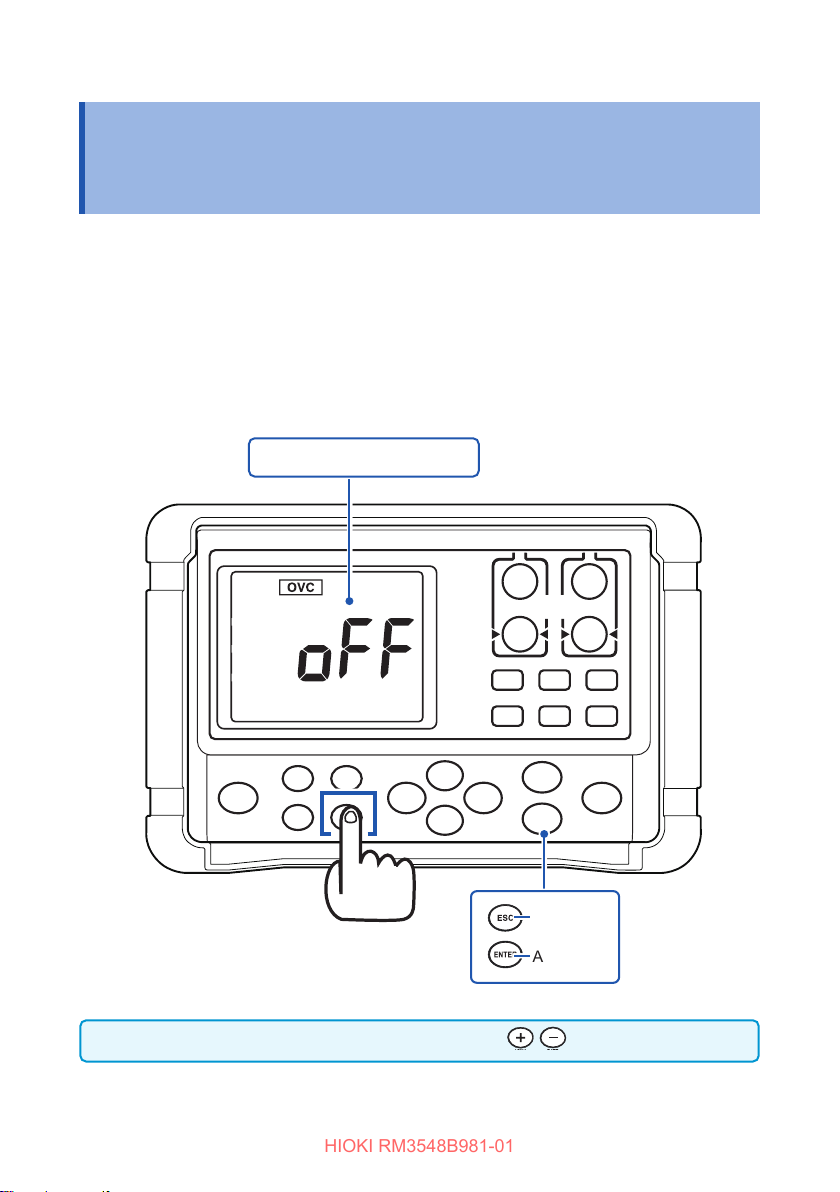
This function automatically compensates for an oset voltage caused by thermal EMF
or an internal oset voltage.
(OVC: Oset Voltage Compensation)
See: “Appx. 6 Eect of Thermoelectromotive Force (Thermal EMF)” (p. Appx.8)
The function uses the resistance value measured when a measurement current ows,
R
and that measured when no measurement current ows,
P
resistance value
R
-
R
.
P
Z
oFF (factory default) ↔ on
R
, to display the actual
Z
The OVC function can also be toggled ON/OFF with .
58
Press and hold
Toggles the OVC function ON/OFF.
([AVG (OVC)] key)
Cancel
Apply
Page 66
Compensating for Thermal EMF Oset (Oset Voltage Compensation Function: OVC Function)
HIOKI RM3548B981-01
IMPORTANT
• When the oset voltage compensation function is ON (the OVC indicator is lit),
the measured value will be slow to refresh.
• The OVC function cannot be used in the 3k
automatically turned OFF.
• When the oset voltage compensation function is changed, the zero adjustment
function is cancelled.
• When the measurement target has a high inductance, it is necessary to adjust
the delay time. (p. 60)
Start with a longer delay time than necessary, and decrease the time gradually,
watching the measured value.
• If the measurement target has a low heat capacity, the oset voltage
compensation function may have no eect.
range or higher. The function is
Ω
59
Page 67
Setting the Delay Time for Measurement (Delay Function)
HIOKI RM3548B981-01
4.5 Setting the Delay Time for Measurement (Delay Function)
This function adjusts the time for measurement to stabilize by inserting a waiting
period after use of the OVC or the auto range function to change the measurement
current. When this function is used, the instrument waits for its internal circuitry to
stabilize before starting measurement, even if the measurement target has a high
reactance component.
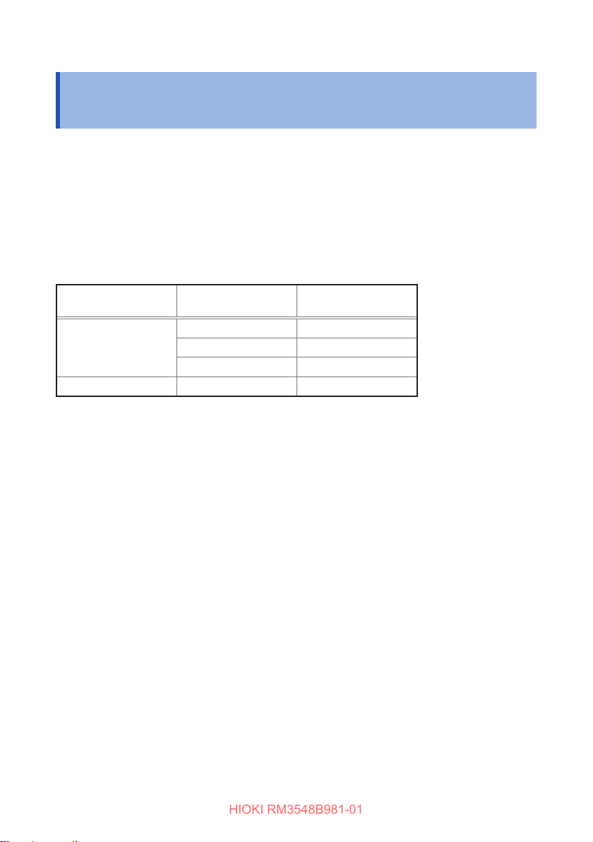
The PrSEt (preset value) depends on the range used and the oset voltage
compensation function.
Preset OVC delay value (factory default) (Unit: ms)
Measurement
current
Lo
Hi 300m
Range Delay time
3m
to 30m
Ω
300m
30
Ω
to 3
Ω
to 300
Ω
Ω
Ω
Ω
200
50
30
200
60
Page 68
Setting the Delay Time for Measurement (Delay Function)
−−=
V
O
IR
n
R
L
t 1l
HIOKI RM3548B981-01
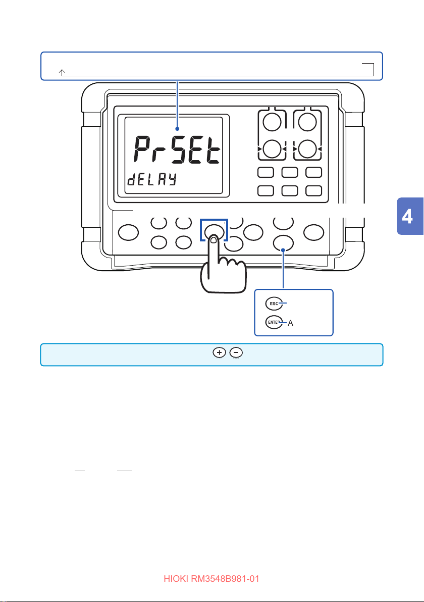
PrSEt (preset) → 10 ms → 30 ms → 50 ms → 100 ms → 300 ms → 500 ms → 1000 ms
Press the [] (DELAY) key to display a selection screen.
The delay time can also be specied with .
Delay time guideline
• If the measurement target, for example, is an inductor that takes longer to stabilize
after applying a measurement current, and it cannot be measured with the initial
delay (preset), adjust the delay. Set the delay time to approximately ten times the
following calculation so that the reactance component (inductance or capacitance)
does not aect the measurement.
• Start with a longer delay time, and decrease the time gradually, watching the
measured value.
• As the delay is longer, the measured value display is slower to refresh.
Press and hold
L
: Measurement target inductance
Measurement target resistance + lead wire resistance +
R
:
contact resistance
I
: Measurement current (see: “Accuracy” (p. 113))
V
: Open-circuit voltage (see: “Accuracy” (p. 113))
O
Cancel
Apply
61
Page 69
Switching the Measurement Current (In the 300mΩ Range)
HIOKI RM3548B981-01
4.6 Switching the Measurement Current (In the
300m
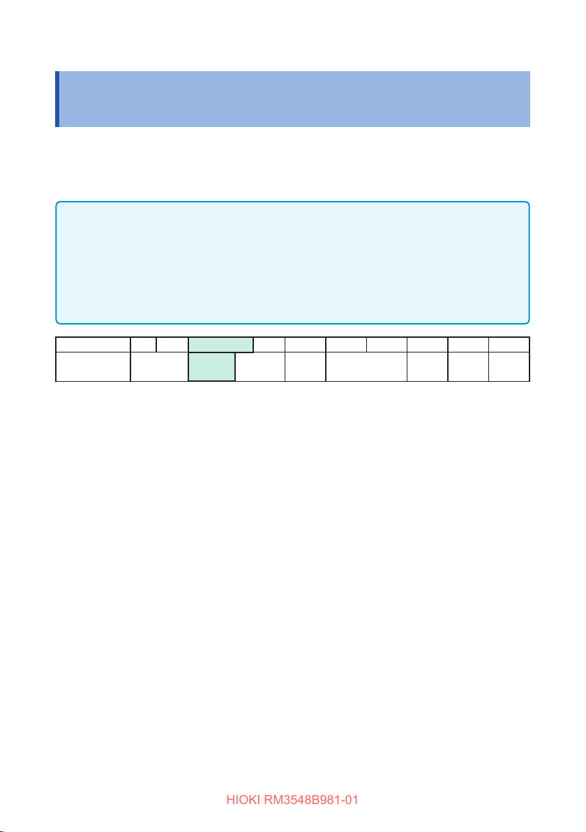
With this instrument, the measurement current for the 300mΩ range can be changed to 300
mA (100 mA at the time of shipment from the factory). This makes it possible to measure large
current wiring under conditions that are similar to the actual usage conditions. It is also useful
when performing measurement in an environment with external noise.*
IMPORTANT
• When the measurement current is set to 300 mA, a larger amount of power is
consumed for the measurement target.
• If highly accurate measurement is required, use a measurement current of 100
mA.
• When the measurement current is changed, the zero adjustment values are
cleared.
Range [Ω] 3m 30m 300m 3 30 300 3k 30k 300k 3M
Measurement
current [A]
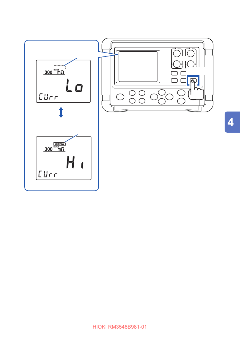
Press and hold the
and 300 mA.
Holding the
normal state.
key causes either Lo/Hi [CUrr] to display, and then the display reverts to the
[▼]
Range)
Ω
1
1 300 m 100 m 10 m 1 m 100 µ 5 µ 500 n
key to switch between the two measurement currents:100 mA
[▼]
62
Page 70
Switching the Measurement Current (In the 300mΩ Range)
HIOKI RM3548B981-01
When Lo is selected
(100 mA)
Not lit
[▼] key
When Hi is selected
(300 mA)
Blinking
When measurement is performed with the 300 mA measurement current, the 300 mA
indicator lights up.
*1 When measuring resistance for connection sections (e.g., connector contact,
welded section, caulked section, screw-secured section) through which large
current ows, such as power supply cables and ground cables, it is desirable that
measurement be performed using the maximum current, as far as possible, that
can actually ow through those sections. The following explains the reasons:
• Even in a connection completely free from abnormality, a relatively high resistance
may be indicated at a lower measurement current.
This is due to an oxide lm that is generated around the contact while it is not used.
• Even when it is judged that no abnormality is found using a small current, the
connection sections are occasionally melted when a large current ows.
This problem occurs due to the Joule heat generated by a large current when a
high resistance area is created locally.
63
Page 71

Switching the Measurement Current (In the 300mΩ Range)
HIOKI RM3548B981-01
64
Page 72
Judgment and Conversion
HIOKI RM3548B981-01
5
Functions
This chapter describes the measured value judgment and conversion functions.
“5.1 Judging Measured Values (Comparator Function)” (p. 66)
“5.2 Performing Temperature Rise Test (Temperature Conversion Function (∆T))”
(p. 73)
“5.3 Measuring the Length of a Conductor (Length Conversion Function)” (p. 76)
65
Page 73
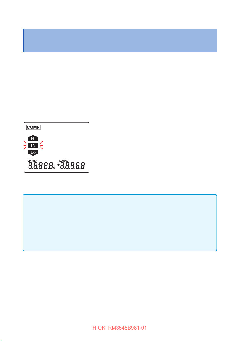
Judging Measured Values (Comparator Function)
HIOKI RM3548B981-01
5.1 Judging Measured Values (Comparator Function)
This function judges a measured value to be Hi (measured value > upper limit), IN
(upper limit ≥ measured value ≥ lower limit), or Lo (lower limit > measured value)
against the set reference value, or upper or lower limit values.
You can check the judgment results by using the followings:
• Display
• Red backlight (default setting: o)
• Buzzer (default setting: o)
• L2105 LED Comparator Attachment (optional)
• There are two dierent judgment methods available: ABS mode and REF% mode.
IMPORTANT
• If ΔT or length conversion function is turned ON, the comparator function
automatically turns OFF.
• If the comparator function is set to ON, it becomes impossible to change the
range (including the auto range). To use the auto range or change the range, set
the comparator function to OFF, and then use the [AUTO] key or [][] keys.
• If the comparator function is set to ON, the interval memory function becomes
unavailable.
66
Page 74
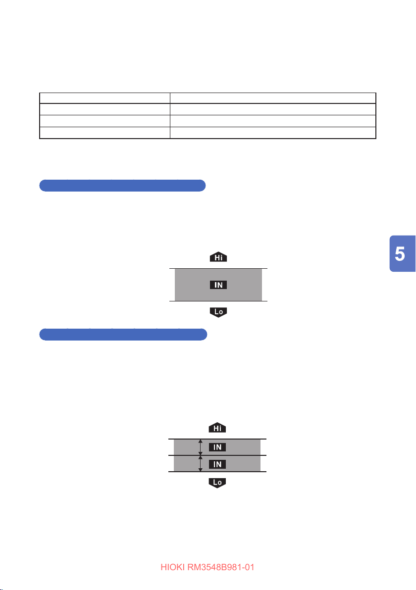
Judging Measured Values (Comparator Function)
HIOKI RM3548B981-01
Before using the comparator function
• If no measured value appears, the comparator judgment is displayed as follows:
If a measurement error occurs, judgment is not performed. (p. 46)
Display Comparator judgment display (COMP lamp)
oF Hi
-oF Lo
----- No judgment
• If the power is turned o during a setting process, any setting changes are lost and
the previous values remain valid. To apply the changes, press the [ENTER] key.
ABS (absolute value judgment) mode
Set the upper and lower limit values for judgment, as absolute values.
Example: Upper limit value ......100.00m
Lower limit value ......80.00m
Upper limit value [Ω]
Lower limit value [
]
Ω
Ω
Ω
(100.00m
(80.00m
)
Ω
)
Ω
REF% (relative value judgment) mode
Set the allowable % of a reference value to determine the upper and lower limit
values for judgment. In REF% mode, the upper and lower limit values cannot be set
separately.
Example: Reference value.........................12.000k
Ω
Upper and lower limit values......±1.00%
Upper limit value [%]
Reference value [
Lower limit value [%]
Ω
]
(12.120k
(12.000k
(11.880k
)
Ω
)
Ω
)
Ω
67
Page 75
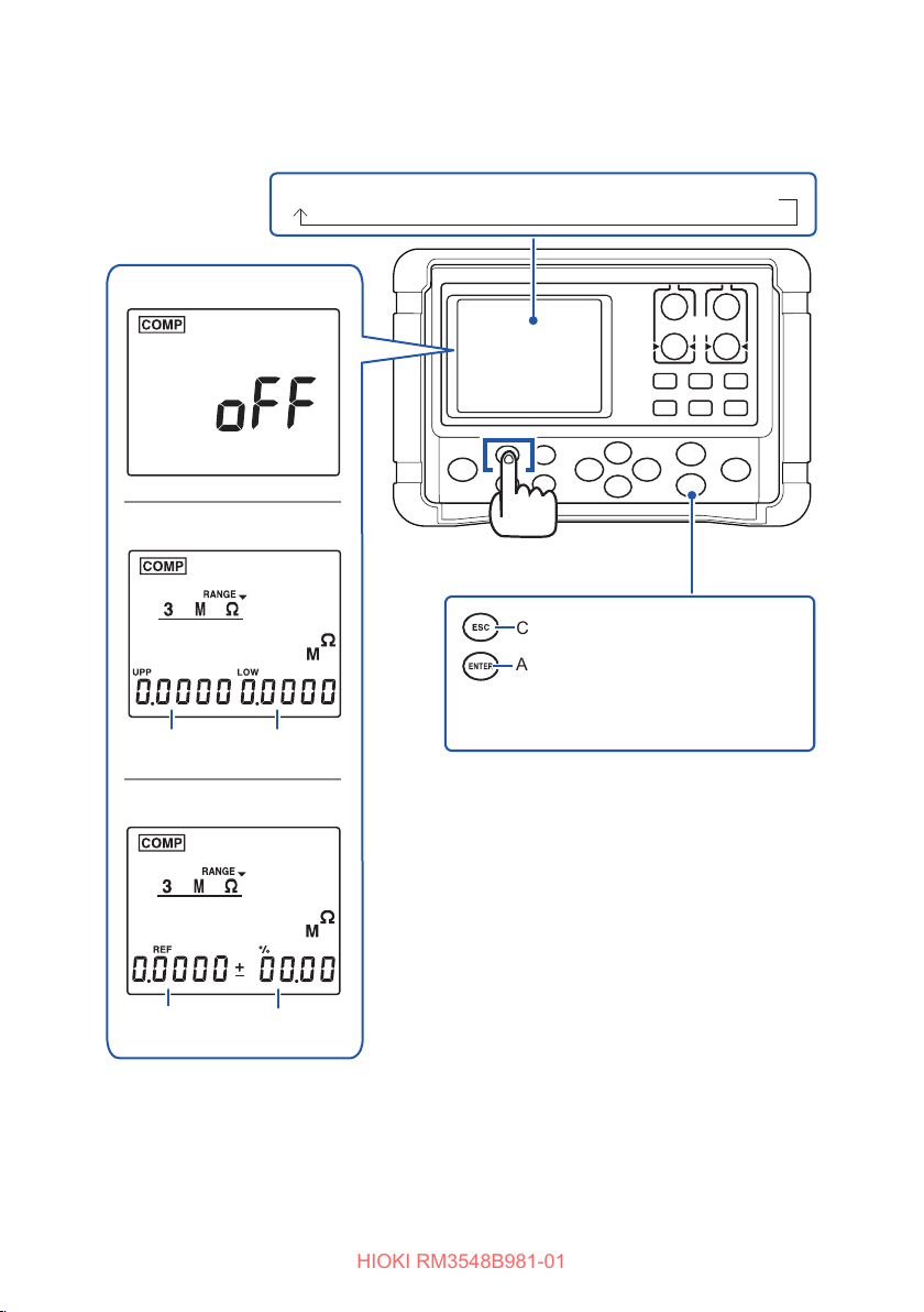
Judging Measured Values (Comparator Function)
HIOKI RM3548B981-01
Turning the comparator function ON/OFF
oFF (factory default) → ON (ABS mode) → ON (REF% mode)
oFF
ABS mode (p. 69)
[COMP] key
Upper limit
value
Lower
limit value
Cancel
Apply (To continue with the reference
value and upper and lower limit
setting process, do not press this
key.)
REF% mode (p. 70)
Reference
value
68
Allowable %
Page 76
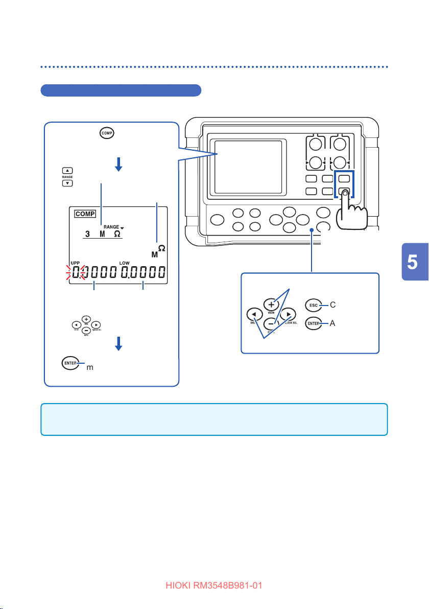
Judging Measured Values (Comparator Function)
HIOKI RM3548B981-01
Judging based on upper and lower limit values (ABS mode)
Upper and lower limit value setting
Use the key to change
the comparator to ABS mode
(p. 68).
Change the range.
Unit of upper and
lower limit values
Change the
range
([][] keys)
Changes values.
Upper limit
value
Apply the setting and
move to the measurement
screen.
Lower limit
value
Upper and lower
limit value setting
Cancel
Apply
Changes settings, digits.
IMPORTANT
Any setting changes cannot be applied when: upper limit value < lower limit value.
69
Page 77
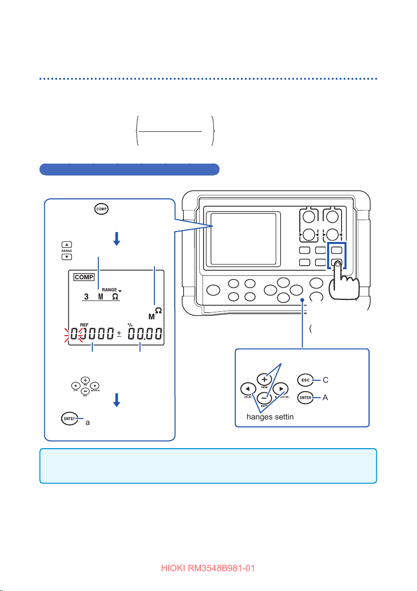
Judging Measured Values (Comparator Function)
HIOKI RM3548B981-01
Judging based on a reference value and allowable range (REF% mode)
In REF% mode, a measured value is displayed as a relative value. The upper and
lower limit values cannot be set separately.
Relative value =
Measured value
Reference value
Reference value and allowable % setting
Use the key to change
the comparator to REF%
mode. (p. 68)
Change the range.
Unit of reference value
Reference
value
Apply the setting
and move to the
measurement screen.
Upper and
lower limit (%)
Value setting
-1 × 100[%]
Change the
range.
([][] keys)
Changes values.
Cancel
Apply
Changes settings, digits.
IMPORTANT
The settings cannot be conrmed when the reference value is set to 0.
70
Page 78
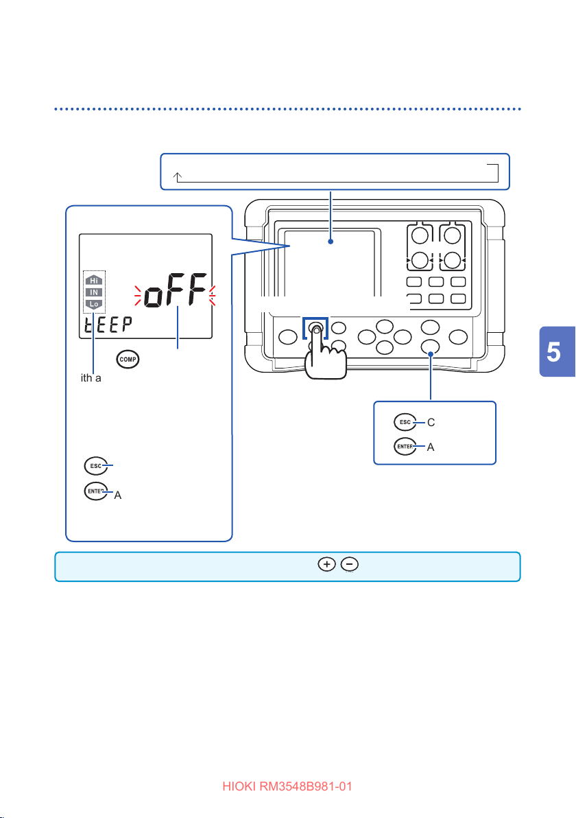
Judging Measured Values (Comparator Function)
HIOKI RM3548B981-01
Conrmingjudgmentresultswiththeredbacklightand
sound (judgment sound function)
The red backlight turns on and the buzzer sounds according to comparator judgment
results.
oFF (factory default) → Hi → in → Lo → Hi-Lo → ALL1 → ALL2
(Beep sound setting)
[COMP] (BEEP SET) key
Changes beep sound.
With a comparator setting
other than OFF selected, when
judgments are provided, the
corresponding judgment mark
is displayed, the red backlight
turns on, and a tone sounds.
Cancel
Press and hold
Cancel
Apply
Apply the setting
and move to the
measurement screen.
The judgment sound can also be selected with .
71
Page 79
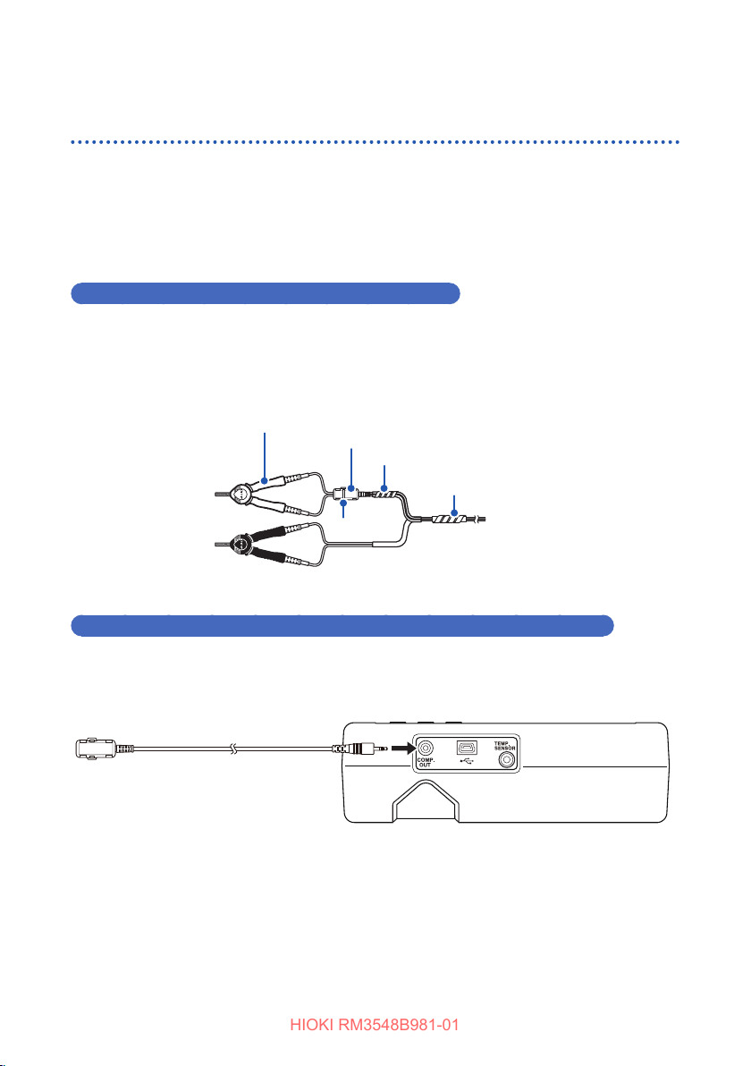
Judging Measured Values (Comparator Function)
JAPAN
HIOKI RM3548B981-01
Verifying a judgment on a handheld device (L2105 LED Comparator Attachment option)
By connecting an L2105 LED Comparator Attachment to the COMP.OUT terminal,
you can obtain the judgment result on a handheld device. The lamp lights up in green
for the IN judgment, and it lights up in red for either Hi or Lo judgment.
Before connecting the L2105 LED Comparator Attachment, be sure to read “Usage
Notes” (p. 7).
Installing the L2105 LED Comparator Attachment
Install the L2105 LED Comparator Attachment wherever you desire.
Example: Install the L2105 LED Comparator Attachment to the test lead, by using the tie band
or spiral tube attached with it.
L2107 Clip Type Leads
L2105 LED Comparator Attachment
Spiral tube (small)
Spiral tube (large)
Tie band
Connecting the L2105 LED Comparator Attachment to the instrument
Connect the L2105 LED Comparator Attachment to the COMP.OUT terminal.
Insert the lamp all the way to the back.
72
Page 80
Performing Temperature Rise Test (Temperature Conversion Function (∆T))
HIOKI RM3548B981-01
5.2 Performing Temperature Rise Test
(TemperatureConversionFunction(∆T))
This function converts the change in the winding resistance into a temperature rise
value, based on the temperature conversion principle (p. Appx.7). It can be used to
estimate the temperature of the motor or the inside of the coil while the power is cut
o based on the change in the winding resistance.
IMPORTANT
• To perform temperature conversion, connect the Z2002 Temperature Sensor to
the TEMP.SENSOR terminal on the side of the instrument. Before connecting the
sensor, be sure to read the following.
See: “2.6 Connecting the Z2002 Temperature Sensor (When Using TC or ΔT)” (p. 36)
• When ΔT is set to ON, the comparator function cannot be turned ON. If length
conversion function is set to ON, ΔT automatically turns OFF.
• If “t.Err” is displayed, the Z2002 Temperature Sensor may not be connected,
or oF is displayed for the temperature. Check the connection of the Z2002
Temperature Sensor.
After the motor and coil are stabilized at room temperature, measure the
1
resistance (
thesevaluestotheinstrument.(p. 75)
Disconnect the test lead from the measurement target.
2
Afterturningothepower,reconnectthetestleadtothemeasurement
3
targetandthenmeasurethetemperaturerisevalue(∆
preset intervals.
(It can be measured easily if the interval memory function is used.) (p. 95)
R
) and instrument ambient temperature (
1
t
), and then input
1
t
to∆
t
) at the
1
n
73
Page 81
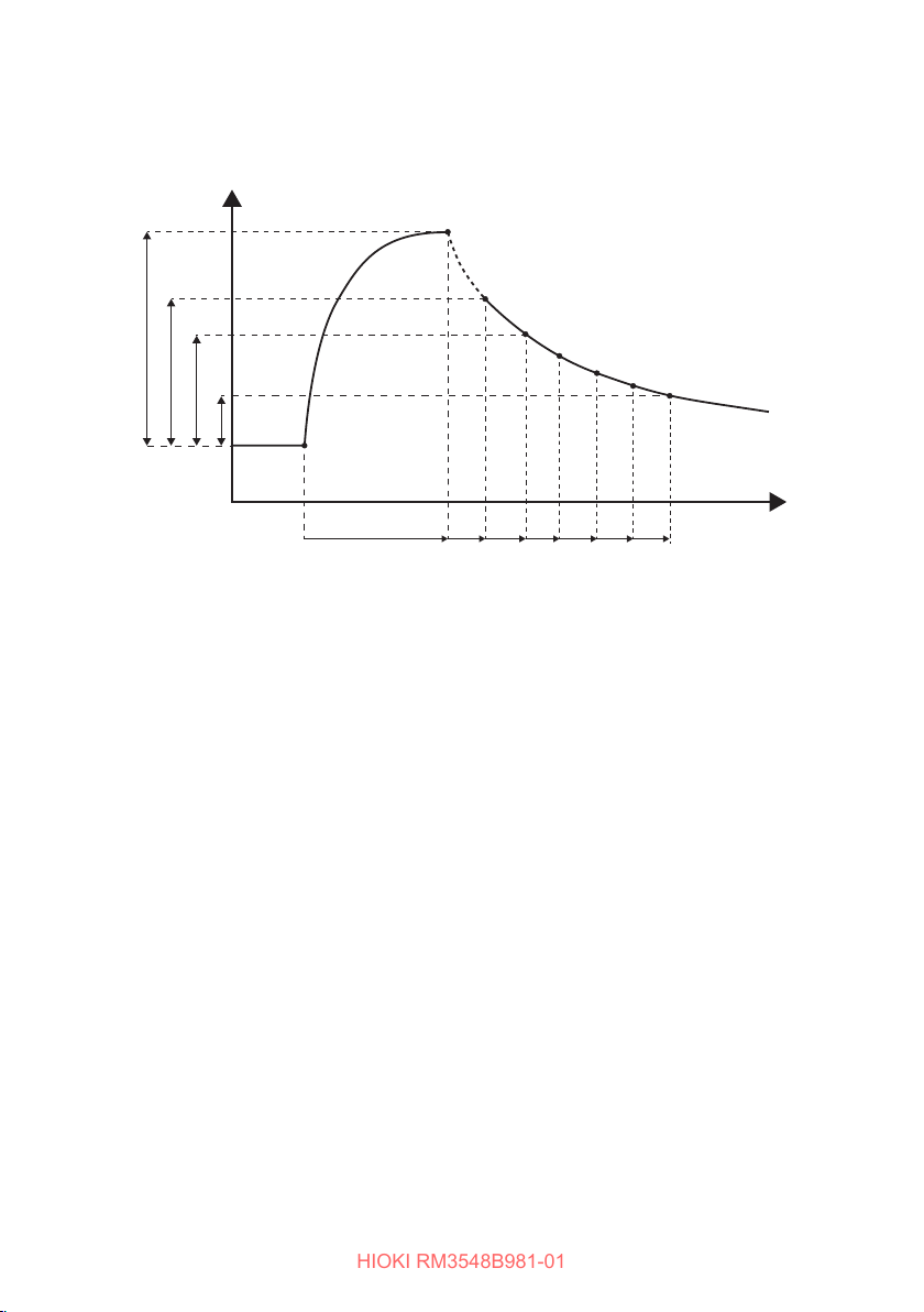
Performing Temperature Rise Test (Temperature Conversion Function (∆T))
HIOKI RM3548B981-01
Drawalinebyconnectingthecollectedtemperaturedata(∆
4
estimatethemaximumtemperaturerisevalue(∆
t
∆
1
t
∆
2
t
∆
Initial temp.
Temp.
n
t
∆
(1) (2)
On
Power
O
(4)
1 2 3
t
(3)
. . . . . . . . . . .
t
to∆
t
), and
1
n
).
Time
n
74
Page 82
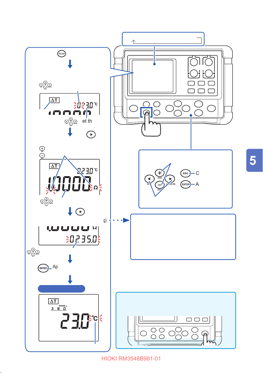
Performing Temperature Rise Test (Temperature Conversion Function (∆T))
HIOKI RM3548B981-01
Use the key to select ∆T.
oFF (factory default) →TC→∆T
(Initial temperature
Set the temperature plus/minus sign
+ (displayed as 0) / -.
Lit
(Initial resistance value
Changes decimal point position, units.
Set the initial resistance value.
(Temperature coecient reciprocal
Set the reciprocal (k) of the temperature
coecient.
Apply the setting and move to
the measurement screen.
t
setting)
1
Set the initial
temperature.
R
setting)
1
k
setting)
[TC/∆T] key
Changes values.
Cancel
Apply
Changes settings, digits.
Guideline for
IEC 60034 recommends the following:
• Copper: k = 235
• Aluminum: k = 225
Reference: “Appx. 5 Temperature
Conversion (ΔT) Function” (p. Appx.7)
k
Measurement screen
(∆T ON)
°C display
If you press the [MEMORY] key during
setting,
t
1
and
R
are set to the values
1
measured immediately before setting.
75
Page 83
Measuring the Length of a Conductor (Length Conversion Function)
HIOKI RM3548B981-01
5.3 Measuring the Length of a Conductor (Length Conversion Function)
This function converts a resistance value to a length to display the length of the
measurement target (such as a conductor).
Press and hold the [TC/∆T](LENGTH) key to display the ON/OFF setting screen for
the length conversion function.
Length [m] =
Example: When the measured resistance is 15
Length [m] =
IMPORTANT
When length conversion function is set to ON, the comparator cannot be turned
ON. If ΔT is set to ON, length conversion function automatically turns OFF.
Measured resistance [
Per meter resistance [Ω/m]
15 [
]
Ω
0.2 [Ω/m]
= 75 [m]
]
Ω
and per meter resistance is 200mΩ/m
Ω
76
Page 84
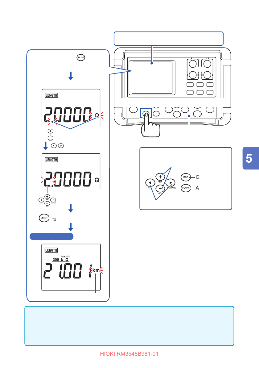
Measuring the Length of a Conductor (Length Conversion Function)
HIOKI RM3548B981-01
Press and hold the (LENGTH)
key to select LENGTH.
(Per meter resistance value setting)
Changes decimal point
position, units.
Move to the value setting.
oFF ↔ ON (per meter resistance value setting)
Press the [TC/∆T](LENGTH) key to display a selection screen.
Press and hold
• Changes decimal point position, units.
• Changes values.
Cancel
Apply
Apply the setting and move
to the measurement screen.
Measurement screen
IMPORTANT
The display format (decimal point position and unit) automatically changes depending
on the range and setting. For details, see the instrument specications (p. 120).
For some ranges, oF is always displayed, because the display range is exceeded,
depending on the setting.
Value setting
(Length conversion
function ON)
Meter display
Moves digits.
77
Page 85

Measuring the Length of a Conductor (Length Conversion Function)
HIOKI RM3548B981-01
78
Page 86
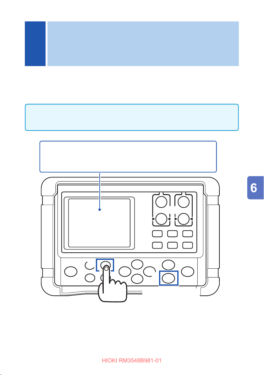
Panel Save and Load
HIOKI RM3548B981-01
6
(Saving and Loading
Measurement Conditions)
The panel save function can save up to nine sets of measurement conditions
displayed at the time of the panel save operation, and the panel load function can
load any set of the measurement conditions at any time. The panel data is retained
even if the instrument is turned o.
• Press the [PANEL] key to display the panel load screen. (p. 81)
• Press and hold the [PANEL] (SAVE/CLEAR) key to display the setting screen for
the panel save/clear function. (p. 80, p. 82)
Conditions that can be saved by panel save:
Resistance measurement range, averaging, delay, comparator, judgment
sound, temperature conversion (ΔT), measurement current change, length
conversion, temperature correction (TC), OVC, and memory mode
Panel load setting ([PANEL] key)
Panel save setting (Press and hold the [PANEL] (SAVE/CLEAR) key)
Apply ([ENTER] key)
79
Page 87
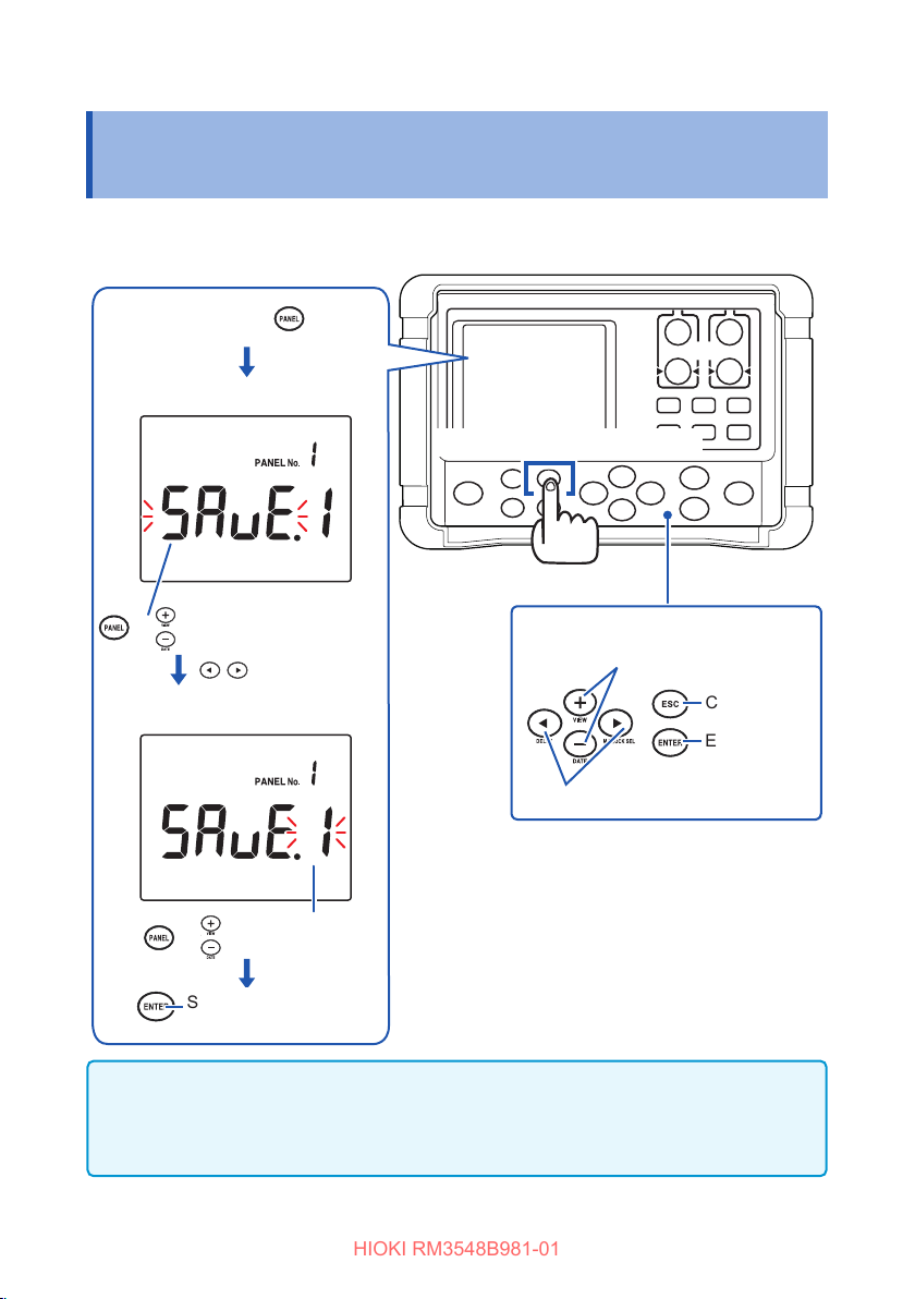
Saving Measurement Conditions (Panel Save Function)
HIOKI RM3548B981-01
6.1 Saving Measurement Conditions (Panel Save Function)
This function saves the set of current measurement conditions.
Press and hold the (SAVE/
CLEAR) key.
Select SAVE.
[PANEL] (SAVE/CLEAR) key
Press and hold
or
SAVE ↔ CLEAR toggle
Moves items.
Select a panel number.
• Select SAVE.
• Select a panel number.
Cancel
Execute
or
Save and move to the
measurement screen.
IMPORTANT
• If the already saved panel number is selected and the [ENTER] key is pressed,
the existing contents are overwritten.
• Zero adjustment values are not saved.
80
Moves items.
Change the panel
number. (1 to 9)
Page 88
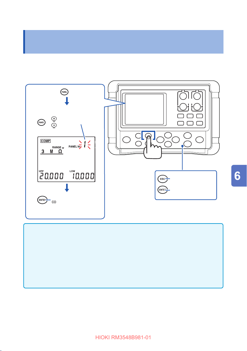
Loading Measurement Conditions (Panel Load Function)
HIOKI RM3548B981-01
6.2 Loading Measurement Conditions (Panel Load Function)
This function replaces the current measurement conditions with a saved set of
measurement conditions.
Press the key.
Select a panel number.
Change the panel
or
number.
(1 to 9)
[PANEL] key
Cancel
Apply and move to the
The measurement
conditions are loaded and
move to the measurement
screen.
measurement screen.
IMPORTANT
• If the number of a panel that is not saved is selected and the [ENTER] key is
pressed, a warning sound is output.
• Zero adjustment values are not read. Zero adjustment can be performed both
before and after panel loading.
• If PANEL No.PrSEt is selected, the measurement conditions are initialized. (Preset
load)
Also see “9.4 Initializing (Reset)” (p. 108) for initialization.
• The panel number is not displayed on the measurement screen.
81
Page 89

Clearing the Contents of a Panel
HIOKI RM3548B981-01
6.3 Clearing the Contents of a Panel
Press and hold the (SAVE/
CLEAR) key.
Select CLEAR.
[PANEL] (SAVE/CLEAR) key
Press and hold
SAVE ↔ CLEAR toggle
Moves items.
Select a panel number.
Moves items.
Change the panel number.
(1 to 9)
Delete the panel and
then move to the
measurement screen.
IMPORTANT
Once deleted, the contents of the panel cannot be restored.
• Select CLEAR.
• Select a panel number.
Cancel
Execute
82
Page 90
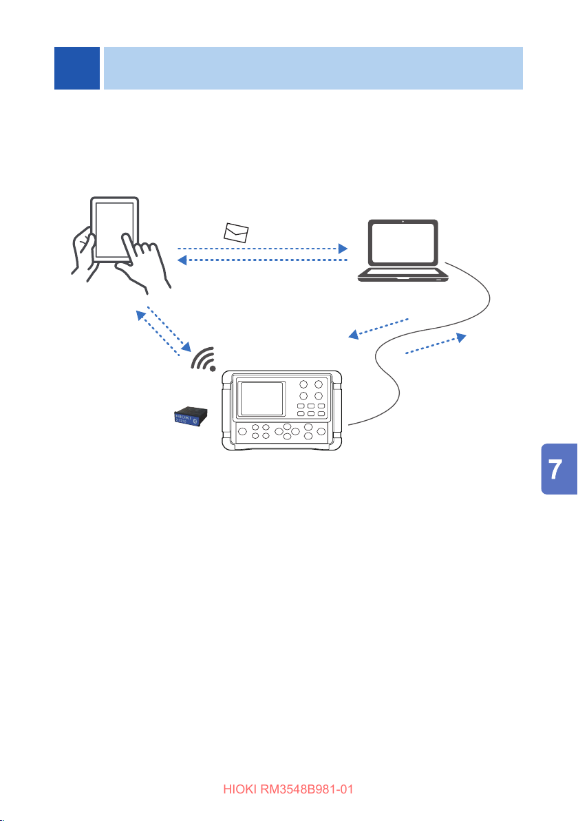
HIOKI RM3548B981-01
7
Using the USB cable enables the instrument to communicate with your computer.
Installing the Z3210 Wireless Adapter (option) enables the instrument to communicate
wirelessly with your smart phone or tablet.
Measured data
(After measurement,
in real time)
Communications Function
GENNECT Cross
Smart phone,
Tablet
Email
Measured data les
(such as .hok and .csv)
Setting threshold values, Registering
and sending prole information
(Before measurement)
Model Z3210
GENNECT One
Computer
Measured data
(After measurement)
USB cable (accessory)
Hioki can deliver application software for each mobile devices and computers.
For details, please visit the GENNECT website.
83
Page 91
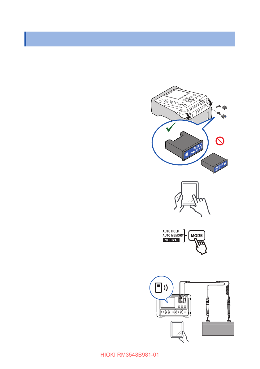
Communicating With a Mobile Device
HIOKI RM3548B981-01
7.1 Communicating With a Mobile Device
Enabling the wireless communications function lets you use your mobile device to do
various works, such as browsing measured data saved in the instrument and creating
reports.
For details, see User Manual on GENNECT Cross (free-of-charge application).
Connect the Z3210 Wireless Adapter
1
(option)intotheinstrument.(p. 32)
OK
NO
Install GENNECT Cross on your mobile
2
device.
Turn on the instrument.
3
Enable the wireless communications
4
function.
When the instrument is turned on for
thersttimeaftertheinstallationofthe
Z3210, the wireless communications
function will be enabled.
Run GENNECT Cross on your mobile
5
communication device and register the
instrument to pair with.
Select various functions to perform
6
measurement.
84
Hold down for at least 1 s.
Page 92
Communicating With a Mobile Device
HIOKI RM3548B981-01
• The communication distance is about 10 m with a clear line of sight. The
communicatable distance may greatly vary depending on the presence of an
obstruction (walls or metallic shielding object) and the distance between the oor
(ground) and the instrument. To ensure stable measurement, make sure that the
radio-wave intensity is sucient.
• GENNECT Cross is free of charge. However, the customer is responsible for the
cost to download the application software and connect to the Internet when using
the software
• GENNECT Cross may not properly operate depending on the mobile device.
• For the rst time (before being paired with any instrument), the app will launch with
the paring setup screen.
• GENNECT Cross’s paring setup screen will automatically pair with the instrument
(up to eight instruments).
• Allow about 5 to 30 s for the instrument to pair with the app after turning on. If the
instrument fails to pair even if one minute has elapsed, relaunch GENNECT Cross
and cycle the instrument.
• The Z3210 uses the 2.4 GHz band wireless technology. When there is a device that
uses the same frequency band such as a wireless LAN (IEEE 802.11.b/g/n) near
your mobile device, the communication may not be established.
IMPORTANT
Placing the instrument on the oor or the ground will cause the communications
distance to decrease. To keep the instrument away from the oor or the ground, it
is recommended to place the instrument on a desktop or a workbench or hang the
instrument from your neck using the neck strap.
85
Page 93
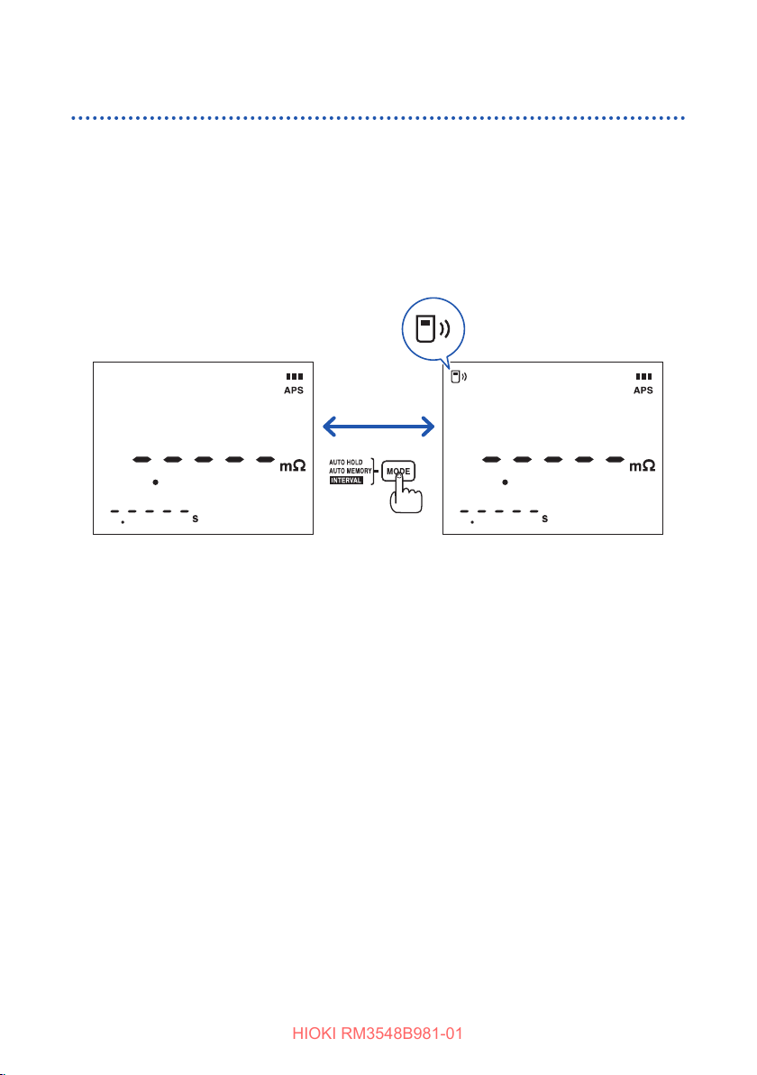
Communicating With a Mobile Device
HIOKI RM3548B981-01
Enabling/disabling the wireless communications function
Holding down the [MODE] key for at least 1 s can enable/disable the wireless
communications function.
When the instrument is turned on for the rst time after the installation of the Z3210,
the wireless communications function will be enabled.
On: Wireless communications function enabled
Blinking: Now communicating
O: Wireless communications function disabled
Hold down for at
Wireless communications
function disabled
least 1 s.
Wireless communications
function enabled
86
Page 94
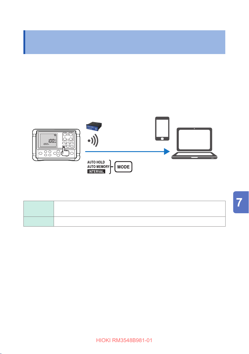
Z3210-to-Excel Direct Data Entry Function (Excel Direct Input Function, HID Function)
HIOKI RM3548B981-01
7.2 Z3210-to-Excel Direct Data Entry Function (Excel Direct Input Function, HID Function)
The human interface device (HID) prole, with which the Z3210 Wireless Adapter is
equipped, is a prole same as that wireless keyboards use.
Preparatory to data entry, open an Excel le on your mobile device or computer and
choose a cell. Freezing the instrument’s display can enter the measured values on
the cells.
The use of this function with the automatic hold function enabled comes in handy.
See “Holding a measured value ”(p. 48)
Enter measured values.
HID ON Choose this option to enter measured values in a Excel le or a text le.
HID OFF Choose this option to use GENNECT Cross.
The setting whether the HID function has been enabled or disabled will not be saved
in the instrument but in the Z3210.
The instrument cannot communicate with GENNECT Cross.
87
Page 95
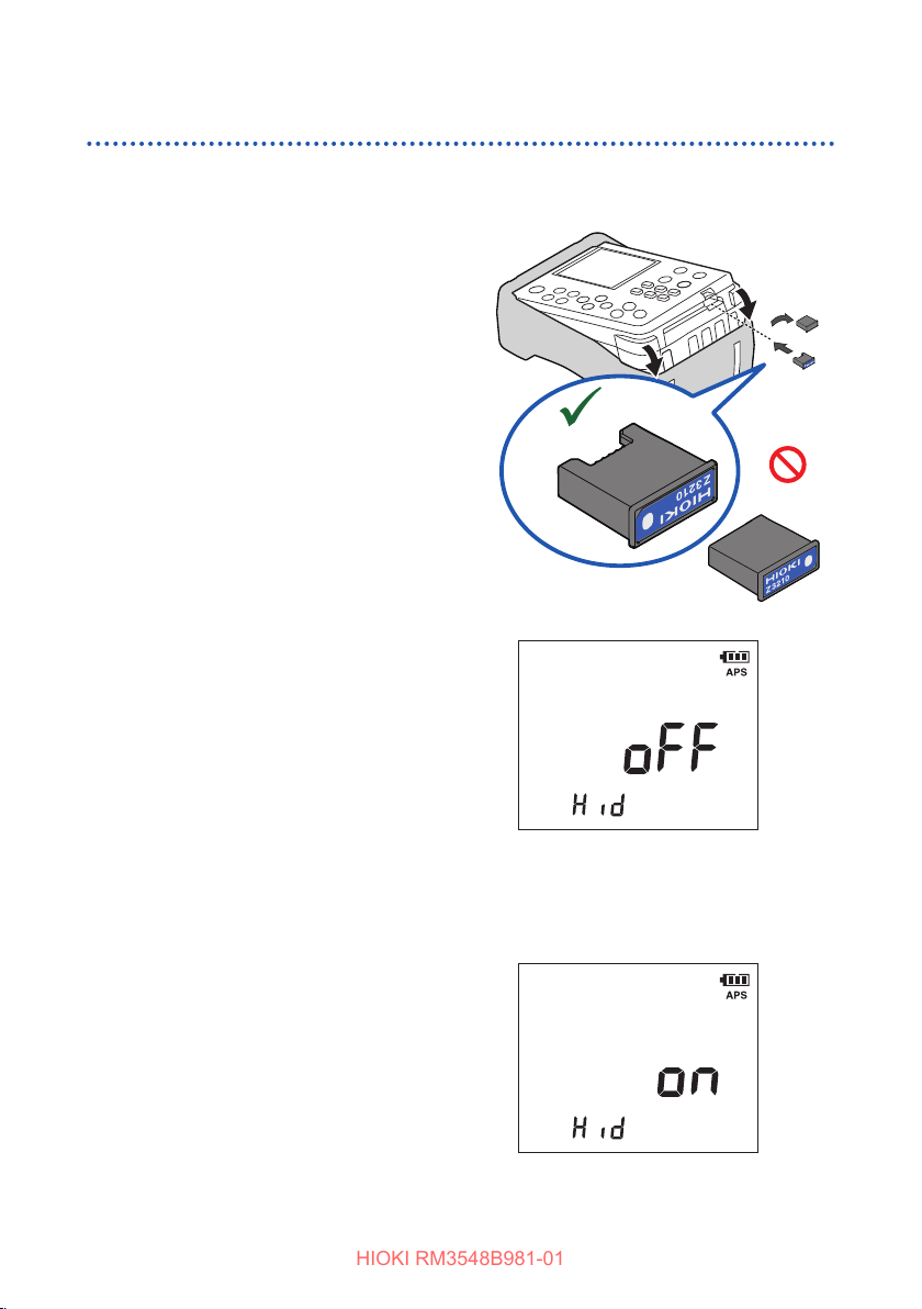
Z3210-to-Excel Direct Data Entry Function (Excel Direct Input Function, HID Function)
HIOKI RM3548B981-01
Enabling/disabling the HID function
Turnotheinstrument.
1
Connect the Z3210 Wireless Adapter
2
(option)intotheinstrument.(p. 32)
OK
While holding down the [COMP] key,
3
press the [POWER] key to display
theHIDsettingconrmationscreen.
The instrument will display the HID
setting saved in the Z3210.
NO
If the[−−−]strings is displayed, an
oldversionofthermwarehasbeen
installed in the Z3210.
Update it to the latest version. Use
version 1.8 or later of GENNECT
Cross to update.
Choose between [oFF] and [on].
4
Conrmyourentry.
5
The display will return to
measurement mode.
88
(When enabled)
Page 96
Z3210-to-Excel Direct Data Entry Function (Excel Direct Input Function, HID Function)
HIOKI RM3548B981-01
IMPORTANT
To switch over from the HID function to GENNECT Cross
If you start GENNECT Cross without canceling the paring between the mobile
device and the instrument, GENNECT Cross
may not be able to recognize the instrument as a connectible device. Follow the
procedure below to reconnect the instrument to GENNECT Cross.
1.Use the Bluetooth
®
setting of your mobile device to delete the instrument.
2.Disable the Z3210’s HID function. (p. 88)
3.
Use the Instrument Setting of GENNECT Cross to reconnect the instrument.
For detail information, please visit the Z3210’s website.
https://z3210.gennect.net
89
Page 97

Z3210-to-Excel Direct Data Entry Function (Excel Direct Input Function, HID Function)
HIOKI RM3548B981-01
90
Page 98
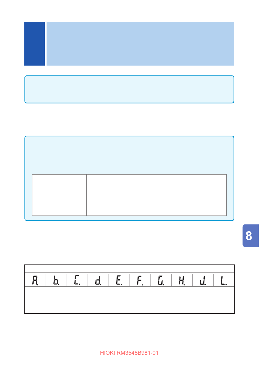
Memory Function (Saving and
HIOKI RM3548B981-01
8
Exporting Measurement Data to a
PC)
IMPORTANT
The memory function cannot operate when the Z3210 communications function is
turned on.
What the memory function does
This function can save a value currently being measured. The saved data is held
even if the instrument is turned o. There are three dierent saving methods:
• Manual memory (up to 1,000 entries) (p. 93)
• Auto memory (up to 1,000 entries) (p. 94)
• Interval memory (up to 6,000 entries) (p. 95)
• Data to be saved in the memory (Some items cannot be displayed only with the
instrument.)
Manual memory, auto
memory
Interval memory
Date and time, measurement value, temperature, resistance
measurement range, averaging, comparator, changed
measurement current, temperature correction (TC), and OVC
Start date and time, measurement value, temperature,
resistance measurement range, averaging, temperature
correction (TC), temperature conversion (∆T), and interval
There are two dierent methods to view saved data.
• Displaying on the instrument (memory display function) (p. 97)
• Exporting to a PC (in USB mass storage mode) (p. 102)
Memory layout
(Maximum number of entries)
Manual or auto memory: 100 entries per block, a total of 1,000 entries for all blocks
Interval memory: A total of 6,000 entries for all blocks
To save up to the maximum amount of memory shown above, all blocks should be used for the
manual or auto-memory, or for the interval memory only. If both types of memory blocks exist,
saving up to the maximum is not possible.
Memory block (10 blocks)
(The number of memory in each block is not xed.)
91
Page 99
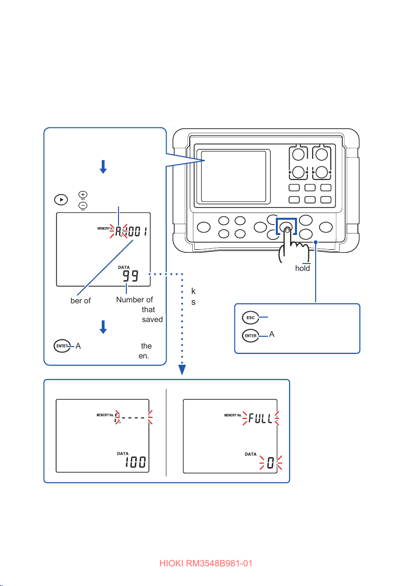
HIOKI RM3548B981-01
Memory blocks
In manual or auto memory mode, the block to save data can be selected. In interval
mode, data is saved in an available free block when the interval starts. In interval
mode, the memory block to save data cannot be specied.
Changing the memory block
Press and hold the []
(M.Block SEL) key.
Select a block.
or
Number of
saved entries
Apply and move to the
measurement screen.
Changes blocks.
Number of
entries that
can be saved
Press and hold
Press the [](M.Block SEL)
key to display a selection
screen.
Cancel
Apply and move to the
measurement screen.
No free memory availableNo data saved
92
Page 100
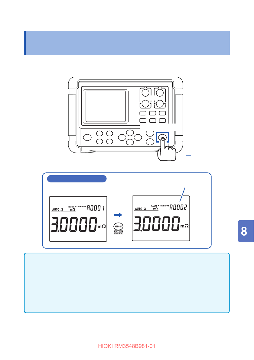
Saving Data at Specied Time (Manual Memory)
HIOKI RM3548B981-01
8.1 SavingDataatSpeciedTime(Manual
Memory)
Press the [MEMORY] key to save the displayed measured value.
[MEMORY] key
During measurement
IMPORTANT
• If a measurement value being held is saved, the memory number to be used
is displayed. When the hold is released, the next available memory number
appears.
• The memory number is incremented by one each time data is saved, and cannot
be specied. If data is accidentally saved, clear the last data item saved (latest
data).
See: “8.5 Clearing Measurement Data (Memory Clear)” (p. 98)
The memory No. blinks (during saving
of data), and the next available memory
number is displayed.
93
 Loading...