


MR8847A
HIOKI MR8847G961-07
MR8847-51
MR8847-52
MR8847-53
Instruction Manual
MEMORY HiCORDER
Be sure to read this manual before using the instrument.
When using the instrument for the
rst time
Part Names and Functions
Preparing for Measurement
Oct. 2022 Revised edition 7
MR8847G961-07 22-10H
p.18
p.27
Troubleshooting
Maintenance and Service
Error Messages
Video
Scan this code to watch the
instructional video(s).
Carrier charges may apply.
[600460807]
p.4
p.431
p.437
EN

Contents
HIOKI MR8847G961-07
Contents
Usage Index ............................................... 1
Introduction ................................................ 2
Verifying Package Contents ..................... 3
Safety Information ..................................... 4
Operation Precautions .............................. 7
1 Overview 17
1.1 Product Overview ......................... 17
1.2 Part Names and Functions .......... 18
1.3 ScreensConguration ................. 21
Explanation of screen contents ................22
1.4 Basic Key Operation .................... 23
1.4.1 Using the HELP Key .................................. 24
1.4.2 Using Mouse to Enable Key Operation ...... 25
2 Preparing for
Measurement 27
2.1 Installing and Removing
Modules ......................................... 28
Channel conguration ...............................29
2.2 Attaching Connection Cables ..... 30
2.3 Preparing Storage Devices .......... 47
2.3.1 Available Storage Devices (Inserting a
CF Card and a USB Flash Drive) ............... 47
2.3.2 Formatting Storage Devices ......................49
2.4 Loading Recording Paper ............ 49
2.5 Supplying Power .......................... 51
2.5.1 Connecting the Power Cord ....................... 51
2.5.2 Connecting an Earthing Wire to the
GND Terminal (Functional Earth Terminal) .. 51
2.5.3 Turning On and Off the Instrument ............. 52
2.6 Setting the Clock .......................... 53
2.7 Adjusting the Zero Position
(zero-adjustment) ......................... 54
2.8 Performing Calibration (When
Model MR8990 is Installed) .......... 55
3 Measurement 57
3.1 Measurement Procedure ............. 57
3.2 Inspecting the Instrument
Before Measurement .................... 59
3.3 Setting Measurement Conditions 60
3.3.1 Measurement Functions ............................ 60
3.3.2 Timebase and Sampling Rate .................... 62
3.3.3 Setting the Recording Length
(Number of Divisions) ................................ 66
3.3.4 Setting Screen Layout ............................... 69
3.4 ConguringInputChannels
Settings ......................................... 70
3.4.1 Channel Setting Procedure ........................ 71
3.4.2 Conguring Analog Channels Settings ....... 73
3.4.3 Conguring Logic Channel Settings ........... 76
3.4.4 Display Sheet ............................................78
3.5 Starting and Stopping
Measurement ................................ 79
3.6 Measurement in Automatic
Range Setting (Auto-Range
Function) ....................................... 82
4 X-Y Recorder 85
4.1 Measurement procedure .............. 86
4.2 Setting Measurement Conditions 87
4.3 Starting and Stopping
Measurement ................................ 88
4.4 Observing X-Y Composite
Curves ........................................... 90
5 Saving/Loading Data
and Managing Files 91
5.1 Data That Can Be Saved and
Loaded ........................................... 93
5.2 Saving Data ................................... 95
5.2.1 Save Types and Setting Procedure ............ 95
5.2.2 Automatically Saving Waveforms ............... 96
5.2.3 Saving Data Selectively (SAVE Key) ........ 103
5.2.4 Saving Waveform Outputting Data to a
Storage Device ........................................ 109
5.3 Loading Data ................................110
5.4 Automatically Loading Settings
(Auto-setup Function) .................113
5.5 Managing Files ............................114
5.5.1 Saving Data ..............................................115
5.5.2 Checking the Contents in a Folder
(Opening a Folder) ....................................118
5.5.3 Creating New Folders ...............................118
5.5.4 Deleting Files and Folders.........................119
5.5.5 Sorting Files ............................................ 120
5.5.6 Renaming Files and Folders .................... 121
5.5.7 Copying a File Into a Specied Folder ...... 122
5.5.8 Printing the File Table...............................123
6 Printing Data 125
6.1 Print Type and Procedure .......... 126
6.2 Setting Auto-printing .................. 127
1
2
3
4
5
6
MR8847G961-07
i

Contents
HIOKI MR8847G961-07
6.3 Manually Printing Data by
Pressing the PRINT Key
(Selection Print) .......................... 130
6.4 Setting the Print Density of the
Waveform .................................... 132
6.5 ConguringthePrinterSettings 133
6.6 Advanced Print Functions ......... 136
6.6.1 Printing the Screenshot ............................ 136
6.6.2 Printing Reports (A4-Sized Print) ............. 136
6.6.3 Printing a List ........................................... 138
6.6.4 Printing the Text Coments ........................ 138
7 Monitoring and
Analyzing Waveforms
on the Waveform
Screen 139
7.1 Reading Measured Values
(Using Cursors A and B) ............ 140
7.2 Specifying the Waveform
Range (Cursors A and B) ........... 145
7.3 Moving the Waveform Display
Position ....................................... 146
7.3.1 Display Position ....................................... 146
7.3.2 Scrolling the Waveforms With the Jog
Dial and Shuttle Ring ............................... 146
7.3.3 Changing Position (Jump Function) .......... 147
7.4 Plotting X-Y Composite Curves 148
7.5 Magnifying and Demagnifying
Waveforms .................................. 150
7.5.1 Magnifying and Demagnifying Waveforms
Horizontally (in the Time Axis Direction)
7.5.2 Zoom Function (Horizontally Magnifying
a Part of Waveforms [in the time axis
direction]) ................................................. 151
7.5.3 Magnifying/demagnifying the
Waveforms Vertically (in the Voltage
Axis Direction) .........................................153
7.6 Monitoring Input Levels
(Level Monitor) ............................ 154
7.6.1 Level Monitor ........................................... 154
7.6.2 Numerical Value Monitor .......................... 155
7.7 Switching the Waveform
Screen Display (Display Menu) . 156
7.7.1 Displaying Upper and Lower Limits on
the Waveform Screen .............................. 156
7.7.2 Displaying Comments on the Waveform
Screen ..................................................... 156
7.7.3 Switching the Waveform Display Width .... 156
7.7.4 Switching Channel Information (U8975,
U8977, and U8978 only) .......................... 157
7.7.5 Switching the Sheet to Be Displayed........ 157
.... 150
7.8 Viewing Waveforms Divided
Into Blocks .................................. 157
8 Advanced Functions 159
8.1 Adding Comments ..................... 160
8.1.1 Adding, Displaying, and Printing the Title
Comment................................................. 160
8.1.2 Adding, Displaying, and Printing the
Channel Comments ................................. 161
8.1.3 Entering Alphanumeric Characters ........... 163
8.2 Displaying Waveforms During
the Writing in the Memory
Simultaneously (Roll Mode) ...... 167
8.3 Overlaying New Waveforms
With Past Waveforms ................. 168
8.4 Setting Channels to Be Used
(Extending the Recording
Length) ........................................ 170
8.5 Converting Input Values
(Scaling Function) ...................... 171
8.5.1 Example of Scaling Settings .................... 174
8.6 Setting the Waveform Position
(Variable Function) ..................... 178
8.7 Fine-Adjusting Input Values
(Vernier Function) ....................... 181
8.8 Inverting the Waveform (Invert
Function) ..................................... 182
8.9 Copying Settings to Other
Channels (Copy Function) ......... 183
8.10 Setting Details of Modules ........ 184
8.10.1 Setting the Anti-aliasing Filter (A.A.F) ....... 186
8.10.2 Setting the Probe Voltage Dividing Ratio .. 186
8.10.3 Setting Model 8967 Temp Unit ................. 187
8.10.4 Setting Model 8969 and U8969 Strain
Unit .......................................................... 188
8.10.5 Setting Model 8970 Freq Unit .................. 189
8.10.6 Setting Model 8971 Current Unit ............. 192
8.10.7 Setting Model 8972 DC/RMS Unit ............ 192
8.10.8 Setting Model MR8990 Digital Voltmeter
Unit .......................................................... 193
8.10.9 Setting Model U8974 High Voltage Unit ... 194
8.10.10 Setting Model U8977 3CH Current Unit .... 195
8.10.11 Setting Model U8979 Charge Unit ............ 196
8.10.12 Setting MR8790 Waveform Generator
Unit .......................................................... 199
8.10.13 Setting MR 8971 Pulse Generator Unit .... 201
8.10.14 Setting U8793 Arbitrary Waveform
Generator Unit ......................................... 203
8.11 Registering Waveforms in the
U8793 Arbitrary Waveform
Generator Unit ............................ 206
ii

Contents
HIOKI MR8847G961-07
8.12 Saving Waveforms Registered
in Model U8793 onto a Storage
Device .......................................... 209
8.13 Setting Output Waveform
Parameters on the Waveform
Screen ......................................... 209
9 Setting the Trigger 211
9.1 Setting Procedure ...................... 212
9.2 Setting the Trigger Mode ........... 213
9.3 Triggering the Instrument
Using Analog Signals ................. 214
9.4 Triggering the Instrument
Using Logic Signals (Logic
Trigger) ........................................ 220
9.5 Triggering the Instrument
attheSpeciedTimeorat
Regular Intervals (Timer
Trigger) ........................................ 222
9.6 Triggering the Instrument
Externally (External Trigger) ..... 226
9.7 Triggering the Instrument
Manually (Manual Trigger) ......... 226
9.8 Setting the Pre-trigger ............... 227
9.8.1 Setting the Trigger Start Point
(Pre-trigger) ............................................. 227
9.8.2 Setting the Trigger Acceptance
(Trigger Priority) ....................................... 229
9.9 Setting the Trigger Timing ......... 230
9.10 Setting the Trigger Logical
Connective (AND/OR) Among
the Trigger Sources .................... 232
9.11 Searching the Measured Data
Using the Trigger Settings ......... 233
10 Numerical Calculation
Functions 235
10.1 Numerical Calculation
Procedure .................................... 236
10.2 Setting the Numerical Value
Calculation .................................. 238
10.2.1 Displaying the Numerical Calculation
Results .................................................... 242
10.3 Judging the Calculation
Results ........................................ 243
10.3.1 Displaying the Judgment Results and
Outputting the Signals .............................. 245
10.4 Saving the Numerical
Calculation Results .................... 246
10.5 Printing the Numerical
Calculation Results .................... 248
10.6 Numerical Calculation Types
and Descriptions ........................ 249
11 Waveform Calculation
Function 253
11.1 Waveform Calculation
Workow ..................................... 254
11.2 Waveform Calculation
Settings ....................................... 256
11.2.1 Displaying the Waveform Calculation
Results .................................................... 258
11.2.2 Setting Constants .................................... 260
11.2.3 Change the Display Method for
Calculated Waveforms ............................. 261
11.3 Waveform Calculation
Operators and Results ............... 264
12 Memory Division
Function 267
12.1 ConguringtheRecording
Settings ....................................... 269
12.2 ConguringtheDisplay
Settings ....................................... 270
13 FFT Function 273
13.1 Overview and Features .............. 273
13.2 OperationWorkow(Reference
Data) ............................................ 274
13.3 Setting the FFT Analysis
Conditions ................................... 275
13.3.1 Selecting the FFT Function ...................... 275
13.3.2 Setting the Data Source for Analysis
(Reference Data) ..................................... 276
13.3.3 Setting the Frequency Range and
Number of Analysis Points. ...................... 277
13.3.4 Decimating and Calculating Data ............. 279
13.3.5 Setting the Window Function ...................280
13.3.6 Conguring the Analysis Result Peak
Value Setting ........................................... 281
13.3.7 Averaging Analysis Results (Waveform
Averaging) ............................................... 282
13.3.8 Highlighting Analysis Results (Phase
Spectra Only) ..........................................285
13.3.9 Conguring the Analysis Mode Settings ... 286
13.3.10 Setting the Display Range of the
Vertical Axis (Scaling) .............................. 290
13.3.11 Setting and Changing Analysis
Conditions on the Waveform Screen ........ 291
11
12
13
6
7
8
9
10
Appx. Ind.
iii

Contents
HIOKI MR8847G961-07
13.4 ConguringtheChannel
settings ........................................ 292
13.5 ConguringtheScreenDisplay
Settings ....................................... 293
13.5.1 Displaying the Running Spectrum ............ 295
13.6 Saving Analysis Results ............ 298
13.7 Printing Analysis Results .......... 299
13.8 Analyzing Waveforms on the
Waveform Screen ....................... 300
13.8.1 Calculating After Specifying the
Calculation Starting Point ......................... 300
13.9 FFT Analysis Modes ................... 302
13.9.1 Analysis Modes and Display Examples .... 302
13.9.2 Analysis Mode Functions ......................... 320
14 Waveform Evaluation
Function 321
14.1 Evaluating Waveforms and
Giving GO/NG Judgments
(MEM, FFT Function) .................. 321
14.2 Setting the Evaluation Area ....... 324
14.3 ConguringtheWaveform
Evaluation Setting ...................... 326
14.4 Setting the Waveform
Evaluation Stopping conditions 327
14.5 Creating the Evaluation Area .... 329
14.6 Details About the Editor
Commands .................................. 330
16.2.2 Connecting the Computer to the
Instrument With the Internet Browser ....... 349
16.2.3 Operating the Instrument With the
Internet Browser ...................................... 350
16.3 Accessing Files on the
Instrument From the computer
(Using the FTP) ........................... 355
16.3.1 Setting the FTP With the Instrument ........356
16.3.2 Connecting the Computer to the
Instrument Using the FTP ........................ 357
16.3.3 Managing Files With the FTP ................... 358
16.4 Transferring Data to the
computer ..................................... 359
16.5 Wave Viewer (Wv) ....................... 360
16.6 ConguringtheUSBSettings
and Connecting the Instrument
to the Computer
Performing Command
Communications) ....................... 361
16.6.1 Conguring the USB Settings With the
Instrument ............................................... 361
16.6.2 Installing the USB Driver .......................... 361
16.7 Controlling the Instrument with
Command Communications
(LAN/USB) ................................... 365
16.7.1 Setting the Instrument .............................. 366
16.8 Operating the Instrument
Remotely and Acquiring Data
Using the Model 9333 LAN
Communicators .......................... 367
(Before
15 Setting the System
Environment 335
16 Connecting the
Instrument to a
Computer 341
16.1 Setting LAN and Connecting
the Instrument to the LAN
Network (Before Using FTP/
Internet Browser/Command
Communications) ....................... 342
16.1.1 Conguring the LAN Settings With the
Instrument ...............................................342
16.1.2 Connecting the Instrument to the
Computer With the LAN Cable ................. 346
16.2 Controlling the Instrument
Remotely (Using an Internet
Browser) ...................................... 348
16.2.1 Setting HTTP With the Instrument ............ 348
17 Controlling the
Instrument Externally 369
17.1 Connection of the External
Control Terminals ....................... 370
17.2 External I/O ................................. 371
17.2.1 External Input (START/EXT.IN1) (STOP/
EXT.IN2) (PRINT/EXT.IN3) ....................... 371
17.2.2 External Output (GO/EXT.OUT1) (NG/
E X T.OU T 2 ) .............................................. 373
17.2.3 External Sampling (EXT.SMPL)................375
17.2.4 Trigger Output (TRIG OUT) .....................377
17.2.5 External Trigger Terminal (EXT.TRIG) ...... 378
18 Specications 379
18.1 GeneralSpecicationsofthe
Instrument ................................... 379
18.2 Common Functions .................... 382
18.3 Measurement Functions ............ 384
18.3.1 Memory Function ..................................... 384
18.3.2 Recorder Function ................................... 385
iv

18.3.3 X-Y Recorder Function ............................386
HIOKI MR8847G961-07
18.3.4 FFT Function ........................................... 387
18.4 Other Functions .......................... 388
18.5 File ............................................... 393
18.6 SpecicationsofModules ......... 395
18.6.1 Model 8966 Analog Unit ........................... 395
18.6.2 Model 8967 Temp Unit ............................. 397
18.6.3 Model 8968 High Resolution Unit ............. 399
18.6.4 Model 8969 Strain Unit, U8969 Strain Unit 401
18.6.5 Model 8970 Freq Unit .............................. 403
18.6.6 Model 8971 Current Unit .......................... 405
18.6.7 Model 8972 DC/RMS Unit ........................ 407
18.6.8 Model 8973 Logic Unit ............................. 409
18.6.9 Model MR8990 Digital Voltmeter Unit ....... 410
18.6.10 Model U8974 High Voltage Unit ............... 412
18.6.11 Model U8979 Charge Unit........................ 414
18.6.12 Model U8793 Arbitrary Waveform
Generator Unit ......................................... 417
18.6.13 Model MR8790 Waveform Generator Unit 420
18.6.14 Model MR8791 Pulse Generator Unit ....... 422
Specications of output connector ..........424
18.6.15 Model U8975 4CH Analog Unit ................425
18.6.16 Model U8977 3CH Current Unit Current
Unit .......................................................... 427
18.6.17 Model U8978 4CH Analog Unit ................429
Contents
13
14
15
19 Maintenance and
Service 431
19.1 Troubleshooting ......................... 432
19.2 Resetting the Instrument ........... 435
19.2.1 Resetting System Settings ....................... 435
19.2.2 Resetting Waveform Data ........................ 436
19.3 Error Messages .......................... 437
19.4 Self-Test (Self-Diagnostics) ....... 442
19.4.1 ROM/RAM Check .................................... 442
19.4.2 Printer Check ...........................................443
19.4.3 Display Check ......................................... 443
19.4.4 Key Check ............................................... 444
19.4.5 System Conguration Check ...................444
19.5 Cleaning the instrument ............ 446
19.6 Disposing of the Instrument
(Removing Lithium Battery) ...... 448
Appendix Appx.1
Appx. 1 Default Values for Major
Settings ............................. Appx.1
Appx. 2 For Reference ................... Appx.2
Appx. 3 About Options ................ Appx.15
Appx.4 FFTDenitions ............... Appx.24
16
17
18
19
Appx. Ind.
Index Ind.1
v

Contents
HIOKI MR8847G961-07
vi

Usage Index
HIOKI MR8847G961-07
Basic measurement procedure
Usage Index
1 Installing the instrument
(p. 27)
Installing the instrument
Installing modules
Connecting cables
Loading the recording paper
Turning on the instrument
2 Setting the instrument
(p. 57)
Selecting a function
Selecting measurement settings
Performing measurement in the automatic
range setting (
Monitoring changes in input signals (p. 211)
Manually triggering the instrument (p. 226)
Entering comments (p. 160)
Freely setting the waveform display (p. 70)
Converting input values (p. 171)
Copying settings to other channels (p. 183)
Eliminating noise (Low-pass lter) (p. 76)
Plotting X-Y composite curves (p. 148)
Locking the operation keys (p. 19)
Formatting a CF Card (p. 49)
p. 82
)
1
2
3
4
5
6
Selecting input channels
3 Measuring input signals (p. 79)
Starting measuring input signals
Completing the measurement
4 Analyzing (
Saving/printing results
5 Completing the measurement (p. 52)
Turning off the instrument
p. 139
Performing analysis
(optionally)
), saving (
Scaling measured values obtained with current
clamp sensors (p. 174)
p. 91
), and printing data (
p. 125
7
8
)
9
10
Appx. Ind.
1
Introduction
HIOKI MR8847G961-07
Introduction
Thank you for purchasing the Hioki MR8847A Memory HiCorder (MR8847-51, MR8847-52, MR8847-53).
To obtain maximum performance from the instrument, please read this manual rst, and keep it handy for
future reference.
The latest edition of the instruction manual
The contents of this manual are subject to change, for example as a result of product
improvements or changes to specications.
The latest edition can be downloaded from Hioki’s website.
https://www.hioki.com/global/support/download/
Product registration
Register your product in order to receive important product information.
https://www.hioki.com/global/support/myhioki/registration/
The optional clamps (p. Appx.15) collectively mean “clamp sensors.”
The following instruction manuals are available for this instrument. Refer to the relevant manual as usage.
Type Contents Printed CD-stored
Read this booklet rst.
Measurement Guide
Instruction Manual
(This document)
Communication Command
Instruction Manual
U8793, MR8790, MR8791
Instruction Manual
Contains basic operating procedures for those
who use this instrument for the rst time.
Contains details and specications regarding the
functions and operations of this instrument.
Contains a list of the communication commands
and their explanations to control the instrument
with a computer.
Contains specications and explanations of
functions/operations of Models U8793 Arbitrary
Waveform Generator Unit, MR8790 Waveform
Generator Unit, MR8791 Pulse Generator Unit,
and SF8000 Waveform Maker.
–
–
Trademarks
• Microsoft, Windows, Excel and Internet Explorer are either registered trademarks or trademarks of
Microsoft Corporation in the United States and other countries.
• CompactFlash is a registered trademark of SanDisk Corporation (USA).
• Sun, Sun Microsystems, Java, and any logos containing Sun or Java are trademarks or registered
trademarks of Oracle Corporation in the United States and other countries.
–
–
2

Verifying Package Contents
HIOKI MR8847G961-07
Verifying Package Contents
When you receive your instrument, inspect it carefully to ensure that no damage occurred during shipping.
In particular, check the accessories, panel switches, and connectors. If damage is evident, or if it fails to
operate according to the specications, contact your authorized Hioki distributor or reseller.
Store the packaging in which the instrument was delivered, as you will need it when transporting the
instrument.
1
Instrument and accessories
Conrm that you received the following items: (One each)
MR8847A Memory HiCorder
(MR8847-51, MR8847-52, MR8847-53)
Accessories
Measurement Guide
Instruction Manual (this
document)
Input cable label USB cable
Model 9231 Recording Paper Paper Roll Axle ×2
Ferrite clamp-on choke
(for LAN/USB cable)
*1
2
3
4
Power cord
5
6
Application disc*2 (CD) (p. 360)
• Model SF8000 Waveform Maker
• Wave Viewer (WV)
• Communication Command Instruction Manual
• U8793, MR8790, MR8791 Instruction Manual
Other options as specied in your order “Appx. 3.1 Options” (p. Appx.15)
*1: When one or more pieces of Model 8967 Temp Unit are installed in the instrument, two ferrite clamp-
on chokes (small) are supplied per module.
*2: The latest version can be downloaded from our website.
7
8
9
10
Appx. Ind.
3

Safety Information
HIOKI MR8847G961-07
Safety Information
This instrument and modules are designed to conform to IEC 61010 Safety Standards, and has been
thoroughly tested for safety prior to shipment. However, using the instrument in a way not described in
this manual may negate the provided safety features.
Before using the instrument, be certain to carefully read the following safety notes:
DANGER
Mishandling during use could result in injury or death, as well as damage to the
instrument. Be certain that you understand the instructions and precautions in
the manual before use.
WARNING
With regard to the electricity supply, there are risks of electric shock, heat
generation, re, and arc discharge due to short circuits. Individuals using an
electrical measuring instrument for the rst time should be supervised by a
technician who has experience in electrical measurement.
Protective Gear
WARNING
This instrument measures live lines. To prevent electric shock, use appropriate
protective insulation and adhere to applicable laws and regulations.
Notation
In this document, the risk seriousness and the hazard levels are classied as follows.
DANGER
WARNING
CAUTION
IMPORTANT
Indicates an imminently hazardous situation that will result in death or serious injury
to the operator.
Indicates a potentially hazardous situation that may result in death or serious injury to
the operator.
Indicates a potentially hazardous situation that may result in minor or moderate injury
to the operator or damage to the instrument or malfunction.
Indicates information related to the operation of the instrument or maintenance tasks
with which the operators must be fully familiar.
Indicates a high voltage hazard.
If a particular safety check is not performed or the instrument is mishandled, this may
give rise to a hazardous situation; the operator may receive an electric shock, may
get burnt or may even be fatally injured.
4
Indicates prohibited actions.
Indicates the action which must be performed.
*
Additional information is presented below.

Symbols Afxed to the Instrument
HIOKI MR8847G961-07
Indicates cautions and hazards. When the symbol is printed on the instrument, refer to the
corresponding topic in the Instruction Manual.
Safety Information
Indicates the ON side of the power switch.
Indicates the OFF side of the power switch.
Indicates a fuse.
Indicates a grounding terminal.
Indicates DC (Direct Current).
Indicates AC (Alternating Current).
Indicates a burn hazard if touched directly.
Standards Symbols
Indicates the Waste Electrical and Electronic Equipment Directive (WEEE Directive) in EU
member states.
Indicates that the product conforms to regulations set out by the EU Directive.
1
2
3
4
5
6
Other Symbols
This manual uses the following symbols to indicate specic information for operating the instrument.
(p. ) Indicates the location of reference information.
CURSOR
(Bold-faced)
[ ]
Names of settings, buttons, and other screen elements are written in bold blue text.
Unless otherwise specied, “Windows” represents Windows 7, Windows 8, or Windows
10.
Menus, commands, dialogs, buttons in a dialog, and other names on the screen and keys
are indicated in brackets.
Indicates that the memory function supports the function.
Indicates that the recorder function supports the function.
Indicates that the X-Y recorder function supports the function.
Indicates that the FFT recorder function supports the function.
Click: Press and quickly release the left button of the mouse.
Right-click: Press and quickly release the right button of the mouse.
Double-click: Quickly click the left button of the mouse twice.
7
8
9
10
Appx. Ind.
5

Safety Information
HIOKI MR8847G961-07
Accuracy
We dene measurement tolerances in terms of f.s. (full scale), rdg. (reading), and setting values
with the following meanings:
f.s. (maximum display value
or scale length)
rdg. (reading or displayed
value)
Setting Indicates the value set as the output voltage, current, or other quantity.
The maximum displayable value or scale length.
For this instrument, the maximum displayable value equals the numerical
number of a presently set range (unit: V/div) multiplied by the number of
divisions (20) on the vertical axis.
Example: When the range is set to 1 V/div, f.s. = 20 V
The value currently being measured and indicated on the measuring
instrument.
Measurement Categories
To ensure safe operation of measuring instruments, IEC 61010 establishes safety standards
for various electrical environments, categorized as CAT II to CAT IV, and called measurement
categories.
DANGER
• Using a measuring instrument in an environment designated with a higher-
numbered category than that for which the instrument is rated could result in a
severe accident, and must be carefully avoided.
• Never use a measuring instrument that lacks category labeling in a CAT II to
CAT IV measurement environment. Doing so could result in a serious accident.
CAT II: When directly measuring the electrical outlet receptacles of the primary electrical
circuits in equipment connected to an AC electrical outlet with a power cord (portable
tools, household appliances, etc.)
CAT III: When measuring the primary electrical circuits of heavy equipment (xed installations)
connected directly to the distribution panel, and feeders from the distribution panel to
outlets
CAT IV: When measuring the circuit from the service drop to the service entrance, and to the
power meter and primary overcurrent protection device (distribution panel)
Distribution Panel
Service Entrance
Service Drop
CAT IV
Power Meter
Fixed Installation
Internal Wiring
CAT III
CAT II
T
Outlet
The applicable measurement category is determined based on the module being used.
Refer to “18.6 Specications of Modules” (p. 395).
6

Operation Precautions
HIOKI MR8847G961-07
Operation Precautions
Before Use
Follow these precautions to ensure safe operation and to obtain the full benets of the various
functions.
DANGER
1
If the connection cables or the instrument are damaged, there is a risk of an
electric shock. Perform the following inspection before using the instrument:
• Before using the instrument, check that the coatings of the connection cables
are neither ripped nor torn and that no metal parts are exposed. Using the
instrument under such conditions could result in an electric shock. Replace the
connection cables with those specied by our company.
• Verify that it operates normally to ensure that no damage occurred during
storage or shipping. If you nd any damage, contact your authorized Hioki
distributor or reseller.
Installing the instrument and modules
Installing the instrument and modules in inappropriate locations may cause a
malfunction of the instrument or may give rise to an accident. Avoid the following
locations:
• Exposed to direct sunlight or high temperatures
• Exposed to corrosive or combustible gases
• Exposed to a strong electromagnetic eld or electrostatic charge
• Near induction heating systems (such as high-frequency induction heating
systems and IH cooking equipment)
• Susceptible to vibration
• Exposed to water, oil, chemicals, or solvents
• Exposed to high humidity or condensation
• Exposed to high quantities of dust particles
WARNING
2
3
4
5
6
7
CAUTION
Do not place the instrument on an unstable table or an inclined place. Dropping or
knocking down the instrument can cause injury or damage to the instrument.
Installing the instrument
To prevent overheating, be sure to leave the specied clearances around the instrument.
• The instrument should be operated only with the bottom or rear side downwards.
• Vents must not be obstructed.
• Do not install the instrument at an angle.
Left side
Vents
At least 5 cm
on all sides
8
9
10
Appx. Ind.
7

Operation Precautions
HIOKI MR8847G961-07
Handling the Instrument and Modules
• Do not use the modules or the cables with circuits that exceed those ratings or
specications.
Doing so may damage the instrument or cause it to become hot, resulting in
bodily injury.
Even including any devices, such as an attenuator, in the input terminal will
never increase the maximum rated voltage to earth. Take care of the connection
not to allow any input voltage to exceed the maximum rated voltage to earth.
• To avoid an electric shock, do not remove the instrument’s cover and the
modules’ cases.
The internal components of the instrument carry high voltages and may
become very hot during operation.
• It is recommended to measure the secondary side of a distribution panel with
the U8974 High Voltage Unit. Do not connect the connection cords on the
primary side of the distribution panel because an unrestricted current ow can
damage the connection cords and facilities if a short-circuit occurs.
DANGER
WARNING
• Each channel of Model U8979 Charge Unit has the BNC terminal and miniature
connector terminal with the common ground. Do not connect cords with each
of the terminals simultaneously to avoid a short-circuit.
• To avoid an electric shock, before removing or replacing an input module,
conrm that the instrument is turned off and that the connection cords are
disconnected.
• To avoid the danger of an electric shock, never operate the instrument with an
input module removed. To use the instrument with a module removed, install a
blank panel over the opening of the removed module.
• To prevent the instrument damage or an electric shock, use only the screws
that are originally installed for securing the module in place.
If you have lost any screws or nd that any screws are damaged, please contact
your Hioki distributor for a replacement.
• Setting the measurement mode to [PreAmp] allows Model U8979 Charge Unit
to constantly provide power (3.0 mA, 22 V) to sensors. Set any measurement
mode other than [PreAmp] or tum off the instrument before connecting a
sensor or probe with a BNC terminal to avoid an electric shock or damage to
the measurement target.
8
Operation Precautions
HIOKI MR8847G961-07
CAUTION
• To avoid damaging modules, do not touch the connectors, installed in the instrument,
to which the modules are connected.
• Model U8979 Charge Unit has miniature connectors with the maximum input charge
of ±500 pC (for six higher-sensitivity range) or ±50,000 pC (for six lower-sensitivity
range). Inputting a charge that exceeds these value causes damage to the instrument.
• Use an acceleration sensor with a built-in pre-amplier that conforms to the
specication of Model U8979 (3.0 mA, 22 V). Using a inapplicable sensor may cause
damaging itself.
• To avoid damage to the instrument, protect it from physical shock when transporting
and handling it. Be especially careful to avoid physical shock due to dropping it.
• The mounting screws must be rmly tightened or the module may not perform to
specications, or may even fail.
• Before carrying the instrument, disconnect all cables and remove the CF card, USB ash drive,
and the recording paper.
• Displayed waveforms can frequently uctuate due to induction potential even when no voltage
is applied. This, however, is not a malfunction.
• This instrument may cause interference if used in residential areas. Such use must be avoided
unless the user takes special measures to reduce electromagnetic emissions to prevent
interference to the reception of radio and television broadcasts.
1
2
3
4
5
6
7
8
9
10
Appx. Ind.
9

Operation Precautions
HIOKI MR8847G961-07
Handling the printer and the recording paper
WARNING
The print head and surrounding metal parts can become hot. Be careful to avoid
touching these parts.
CAUTION
Be careful not to cut yourself with the paper cutter.
• Please use only the specied recording paper. Using non-specied paper may not only result in
faulty printing, but printing may become impossible.
• If the recording paper is skewed on the roller, paper jams may result.
• Always use the paper cutter to cut the printed paper. Excessive paper dust can accumulate on
the roller if the paper is cut with the print head, which may result in paper jams or white streaks
in the printing.
Storing data recordings
The recording paper is thermally sensitive. Observe the following precautions to avoid paper discoloration
and fading.
• To avoid paper discoloration, do not expose it to direct sunlight. Store the paper at no more than 40°C
and 90% RH.
• Store the paper away from dew and damp places.
• Make photocopies of recording printouts that are to be handled or stored for legal purposes.
• If the thermal paper is exposed to an organic solvent such as alcohol or ketone, it may no longer
develop properly, and recorded data may fade. Keep the printer papers away from exible PVC lms
and pressure sensitive tapes including scotch tapes because they contain organic solvents.
• Also, the thermal recording paper is ruined by contact with wet diazo copy paper.
Avoid exposure to direct
sunlight.
Do not store the paper at
more than
40°C (104°F) and 90%
RH.
Avoid exposure to volatile
organic solvents like
alcohol, ethers, and
ketones.
Avoid contact with exible
PVC lms or adhesive
tapes such as scotch
tapes.
Storing recording paper
• Store thermal paper where its temperature will not exceed 40°C.
• The paper will deteriorate if exposed to light for a long time; thus, do not remove the wrapping paper
from the roll until it is ready to be used.
10
Avoid stacking with wet
Diazo copy paper.
Handling storage devices
HIOKI MR8847G961-07
•
Do not remove the storage device while it is being accessed by the instrument (while
the SAVE key is lit in blue). Data saved on the device could be lost.
• Do not turn off the instrument while it is accessing the storage device (while the SAVE
key is lit up in blue). Data saved on the device could be lost.
•
Do not carry the instrument with a USB ash drive left connected. Damage could
result.
•
Exercise care when using such products because static electricity could damage the
storage device or cause a malfunction of the instrument.
•
Do not subject the SSD to extreme shock or vibration. Shock can cause it to be
damaged.
Operation Precautions
CAUTION
1
2
3
IMPORTANT
• No compensation is available for loss of data stored on the built-in drive (SSD) or a removable
storage device, regardless of the content or cause of damage or loss. Be sure to back up any
important data saved on the built-in drive (SSD) or the removable storage device.
• Use only CF cards (no adapter is required to insert a CF card into the instrument.) or USB ash
drive sold by Hioki.
• Compatibility and performance are not guaranteed for PC cards or USB ash drive made by
other manufacturers. You may be unable to read from or save data to such cards.
■Hioki optional CF cards (with an adapter accompanying) and USB ash drive
Model 9728 PC Card 512M, Model 9729 PC Card 1G, Model 9830 PC Card 2G
Model Z4006 USB Drive
• With some external storage device, the instrument may not start up if it is turned on while the
external storage device is inserted. In such a case, turn on the instrument rst, and then insert
the external media. Prior testing is recommended.
• The instrument does not support particular kind of USB ash drives, such as those that require
ngerprint authentication or a password.
• When saving or loading data, insert the storage device before selecting data to be saved.
When the storage device is not inserted, no devices are not displayed in the le list.
• All storage devices (built-in drive [SSD], USB ash drive, and CF card) have a limited service
life. After extensive use for a long period, saving and loading data may be disabled. In that
case, replace the device with a new one.
• The built-in drive (SSD) is a consumable part. When the saved data reaches the capacity (about
60 TB), no further data can be recorded. In such a case, the SSD should be replaced with a
new one.
• When the instrument is left powered off for a one year or more, the data saved on the built-in
drive (SSD) may be lost. Be sure to back up the data if the instrument is left powered off for a
long time.
• Devices the automatic data saving supports are the built-in drive (SSD), a USB ash drive, and
a CF card.
4
5
6
7
8
9
10
Appx. Ind.
11
Operation Precautions
HIOKI MR8847G961-07
Before connecting cables
When measuring power line voltage
• Connect the connecting cables to only the secondary side of a breaker. Even
if a short-circuit occurs on the secondary side of the breaker, the breaker will
interrupt a short-circuit current. Do not connect them to the primary side of the
breaker because an unrestricted current ow could damage the instrument and
facilities if a short circuit occurs.
• To prevent an electrical shock and a bodily injury, do not touch any input
terminals on the VT (PT), CT or the instrument when they are in operation.
• Do not leave the measurement cables connected to the instrument in an
environment where voltage surges exceeding the maximum input voltage may
occur. Subjecting the instrument to such a voltage may result in damage to the
instrument or a serious accident.
• Do not short-circuit two wires to be measured by bringing the connection
cables into contact with them. Arcs or such grave accidents are likely to occur.
• To avoid a short-circuit or an electric shock, do not touch the metal parts of the
connecting cable clips.
• To avoid electrical shock, be careful to avoid shorting live lines with the
connection cable chips.
DANGER
WARNING
To avoid an electric shock and a short-circuit accident, use only the specied test
leads to connect the instrument input terminals to the circuit to be tested.
• To avoid an electric shock, do not exceed the lower of the ratings shown on the
instrument and connection cords.
To prevent an electric shock, conrm that the white or red portion (insulation
layer) inside the cable is not exposed. If a color inside the cable is exposed, do
not use the cable.
CAUTION
• The cable is hardened in the freezing temperatures. Do not bend or pull it to avoid
tearing its shield or cutting cable.
• Connecting cables to the BNC jacks on modules
• Do not use any cable terminated with a metal BNC connector. If you connect a metal
BNC cable to an insulated BNC connector, the insulated BNC connector and the
instrument may be damaged.
To prevent cable damage, do not step on cables or pinch them between other objects.
Do not bend or pull on cables at their base.
12
IMPORTANT
• Use only the specied connection cables. Use of any cable not specied by our company does
not allow safe measurements due to poor connection or other reasons.
• For detailed precautions and instructions regarding connections, refer to the instruction
manuals for your modules, connection cables, etc.

Before connecting a logic probe to the measurement object
Functional Earth
HIOKI MR8847G961-07
DANGER
To avoid an electric shock, a short-circuit, and damage to the instrument, observe
the following precautions:
• The ground pin in the logic connector (plug) of Model 9320-01 Logic Probe and
Model 9327 Logic Probe are not isolated from the instrument’s ground (common
ground).
Supply power to the instrument with the provided power cord and measurement
objects from a single mains circuit.
Connecting the instrument and a measurement object to different mains circuits
from one another or using a non-grounding power cord may cause damage to
the measurement object or the instrument because of current owing through
the logic probes resulting from the potential difference between the grounds of
the different wiring systems.
To avoid that, we recommend the following connection procedure:
Connect the provided power cord
to the instrument and supply
power from the same outlet as the
measurement object.
Measurement
Object
Logic probe
Operation Precautions
Memory
HiCorder
1
2
3
4
Connect the measurement object’s
ground to the GND terminal
(functional earth terminal) of the
instrument.
(Always supply power from the
single mains circuit.)
Refer to
Wire to the GND Terminal (Functional
Earth Terminal)” (p. 51).
Before turning on the instrument
• To avoid electrical accidents and to maintain the safety specications of this
instrument, connect the power cord provided only to an outlet.
• Before turning the instrument on, make sure the supply voltage matches that
indicated on its power connector. Connection to an improper supply voltage
may damage the instrument and present an electrical hazard.
“2.5.2 Connecting an Earthing
Measurement
Object
GND
WARNING
CAUTION
Logic probe
Memory
HiCorder
Terminals
5
6
7
8
9
Avoid using an uninterruptible power supply (UPS), DC/AC inverter with rectangularwave or pseudo-sine-wave output to power the instrument. Doing so may damage the
instrument.
10
Appx. Ind.
13

Operation Precautions
HIOKI MR8847G961-07
Before connecting the instrument to an external device
DANGER
To avoid electrical hazards and damage to the instrument, do not apply voltage
exceeding the rated maximum to the external control terminals.
I/O terminals Maximum input voltage
Instrument START/EXT.IN1 −0.5 V to 7 V DC
STOP/EXT.IN2 −0.5 V to 7 V DC
PRINT/EXT.IN3 −0.5 V to 7 V DC
GO/EXT.OUT1 50 V DC, 50 mA DC, 200 mW
NG/EXT.OUT2 50 V DC, 50 mA DC, 200 mW
EXT.SMPL −0.5 V to 7 V DC
TRIG OUT 50 V DC, 50 mA DC, 200 mW
EXT.TRIG −0.5 V to 7 V DC
U8793
Arbitrary Waveform
Generator Unit
IN −0.5 V to 7 V DC
OUT 30 V DC, 50 mA DC
WARNING
To avoid an electric shock or damage to the equipment, always observe the
following precautions when connecting the cables to external control terminals.
• Always turn off the instrument and any devices to be connected before making
connections.
• Be careful to avoid exceeding the ratings of the external control terminals and
the external connectors.
• The external control terminals use the same GND as the instrument. Ensure
that devices and systems to be connected to the external control terminals are
isolated from one another as required.
CAUTION
To avoid equipment failure, do not disconnect the USB cable while communications are
in progress.
• Use a common ground for both the instrument and the connection equipment. Using
different ground circuits will result in a potential difference between the instrument’s
ground and the connected equipment’s ground. If the cable is connected while such a
potential difference exists, it may result in equipment malfunction or failure.
• Before connecting or disconnecting any cable, always turn off the instrument and
the device to be connected. Failure to do so may result in equipment malfunction or
damage.
• After connecting the communications cable, tighten the screws on the connector
securely. Failure to secure the connector could result in equipment malfunction or
damage.
Disc precautions
14
• Exercise care to keep the recorded side of discs free of dirt and scratches. When writing text on a
disc’s label, use a pen or marker with a soft tip.
• Keep discs inside a protective case and do not expose to direct sunlight, high temperatures, or
high humidity.

• Hioki is not liable for any issues your computer system experiences in the course of using this
HIOKI MR8847G961-07
disc.
When the instrument is not used for a long period
• To avoid straining some parts of the printer, and to prevent dirt adhering to the print head, close
the printer cover.
• Perform test prints (printer check) three or four times before using the printer that has been in
storage and has left unused for a long period.
Operation Precautions
1
Precautions during shipment
Store the packaging in which the instrument was delivered, as you will need it when transporting
the instrument.
2
3
4
5
6
7
8
9
10
Appx. Ind.
15

Operation Precautions
HIOKI MR8847G961-07
16

1
HIOKI MR8847G961-07
Overview
1.1 Product Overview
This instrument enables you to measure and analyze various waveforms with simple methods.
You can use this instrument mainly for facility diagnosis, preventive maintenance, and troubleshooting.
Sturdy body with easy-to-grasp
handle installed
You can install this portable instrument anywhere.
1
Overview
Logic modules can measure
signals input on 64 channels
Easy loading of recording paper
High-speed printing
High-speed sampling
at 20 MS/s
Arbitrary Waveform Generator Unit
can output waveforms simulating
measured signals
You can take multiple measurements simultaneously.
You can load the recording paper through one-touch
operation.
You can conduct reliable response evaluation.
You can have the instrument output realistically simulated
waveforms.
17

Part Names and Functions
HIOKI MR8847G961-07
1.2 Part Names and Functions
Left side
Vents
Right side
11
22
33
Printer
(p. 10)
66
77
Front side
Handle
Screen
USB connector (Type B)
11
Connect the USB cable to
operate the instrument with a
computer.
(p. 361)
USB connector (Type A)
22
Connect a USB ash drive or
a mouse. (p. 47)
CF card slot
Operation keys (p. 19)
External control terminals
66
Input an external sampling
signal.
(p. 369)
Connect signal cables to
operate the instrument
externally.
Standard LOGIC
77
terminals
Connect optional Hioki logic
probes.
(p. 30)
44
55
18
88
99
1010
100BASE-TX connector
33
Connect a LAN cable.
(p. 341)
Power switch (p. 52)
44
Flip the switch to turn on and
off the instrument.
: Power-on
: Power-off
GND terminal (Functional
55
earth terminal)
Connect a grounded
conductor.
(p. 51)
Various modules
88
(p. 28), (p. 30)
For details, refer to “8.10
Setting Details of Modules” (p.
184) or “18.6 Specications
of Modules” (p. 395).
Power inlet
99
Connect the provided power
cord. (p. 51)
Serial number
1010
The serial number consists
of 9 digits. The rst two (from
the left) indicate the year of
manufacture, and the next
two indicate the month of
manufacture.
Required for production
control. Do not peel off the
label.
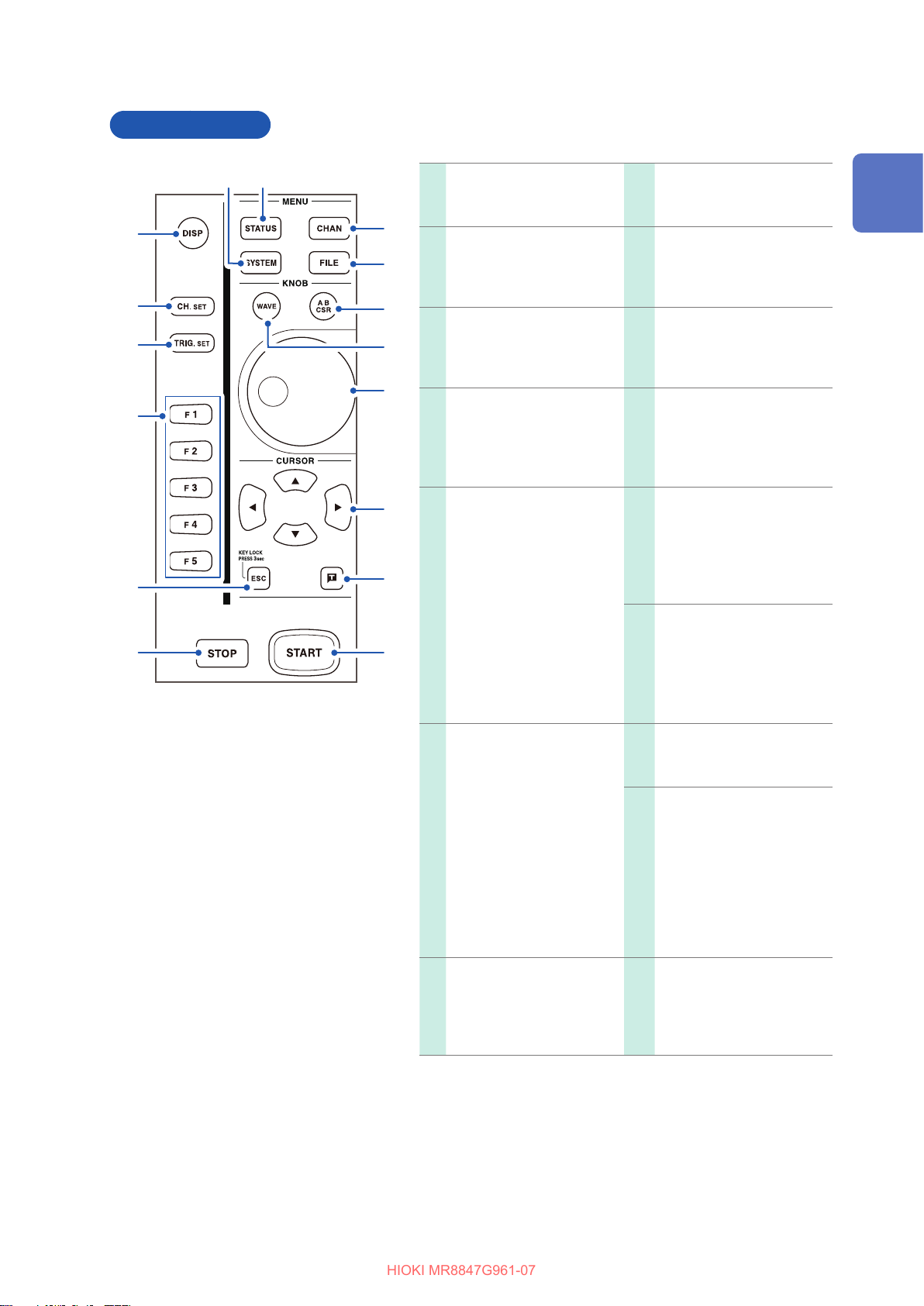
Operation keys
HIOKI MR8847G961-07
Part Names and Functions
8877
11
99
1010
22
33
1111
1212
1313
44
1414
55
66
1515
1616
DISP key
11
Displays the waveform
screen.
CH.SET key
22
Displays the channel
settings window on the
waveform screen (p. 70).
TRIG.SET key
33
Displays the trigger settings
window on the waveform
screen (p. 211).
F key
44
Selects setting items.
ESC key
55
Cancels the last action.
Closes the displayed dialog
and window.
KEY LOCK:
Press and hold the ESC
key for 3 seconds to
engage the key lock
function, which prevents
accidental operation.
Press and hold this key for
3 seconds to disengage
the key lock function.
STATUS key
88
Displays the status screen.
CHAN key
99
Displays the channel
screen.
FILE key
1010
Displays the File screen.
(p. 114)
AB CSR key
1111
(Lights up in red when
selected.)
Sets Cursors A and B. (p.
140)
WAVE key
1212
(Lights up in red when
selected.)
Assigns waveform scrolling
to the jog dial and shuttle
ring. (p. 146)
Inner: Jog dial
1313
Outer: Shuttle ring
Scrolls waveforms display.
(p. 146)
Increases and decreases a
setting value.
(p. 23)
1
Overview
STOP key
66
Stops the measurement in
progress.
Press the key once:
Stops the measurement
in progress after the
instrument records the
specied recording length
of waveforms.
Press the key twice:
Immediately stops the
measurement in progress.
(p. 338)
SYSTEM key
77
Displays the system
screen.
(p. 335)
CURSOR key
1414
Moves the cursor up, down,
left, and right on the screen.
Manual trigger key
1515
Manually trigger the
instrument.
(p. 226)
START key
1616
Starts measurement.
(Lights up in green during
measurement.)
(p. 338)
19

Part Names and Functions
HIOKI MR8847G961-07
1717 1818 1919 2020 2121 2222 2323
PRINT key
1717
Prints waveforms and lists. (p. 125)
COPY key
1818
Prints a screenshot. (p. 136)
FEED key
1919
Feeds paper.
SAVE key (Lights up in blue while the instrument is
2020
accessing a storage device.)
Saves data to a storage device. (p. 91)
The dialog box can be switched between visible and
invisible during auto-saving.
HELP key
2121
Displays help information. (p. 24)
AUTO key
2222
Starts measurement in the auto-range setting.
(p. 82)
TIME/DIV key
2323
Sets the timebase.
20
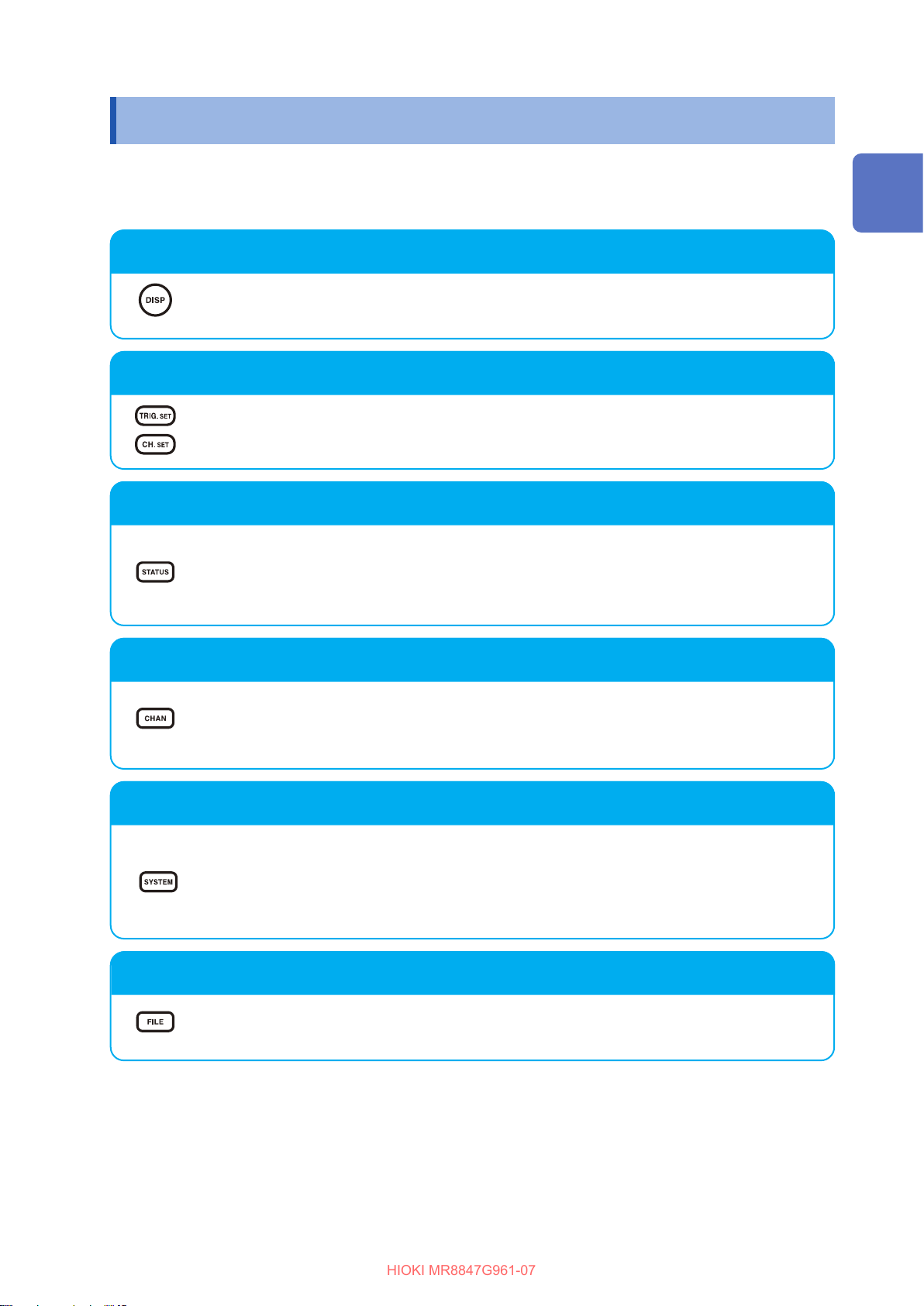
Screens Conguration
HIOKI MR8847G961-07
1.3 Screens Conguration
The screens are congured as listed below. Pressing each of the keys listed below displays a
corresponding screen or window.
The waveform screen can display the trigger settings window, and the channel settings window.
Waveform screen
The display used to observe waveforms.
Congure measurement conditions using the settings window on the right.
Trigger settings window, channel settings window
The display used to congure the trigger settings
The display used to congure the settings of analog channels and logic channels
1
Overview
Status screen
The window used to congure the measurement methods and numerical calculation
settings.
Pressing the STATUS key switches the sheets to be displayed in the following order:
[Status] sheet, [Num Calc] sheet, [Memory Div] sheet, and [Wave Calc] sheet.
Channel screen
The screen used to congure the channel, the scaling, and the comment settings
Pressing the CHAN key switches the sheets to be displayed in the following order:
[Unit List] sheet, [Each Ch] sheet, [Scaling] sheet, and [Comment] sheet.
System screen
The screen used to congure the environment, the le saving, the le printing, and the
interface settings, and to initialize data.
Pressing the SYSTEM key switches sheets to be displayed in the following order:
[Environment] sheet, [File Save] sheet, [Printer] sheet, [Interface] sheet, and [Init]
sheet.
File screen
The screen used to view saved data les in storage devices (a CompactFlash card, the
built-in drive, a USB ash drive, the internal memory).
21
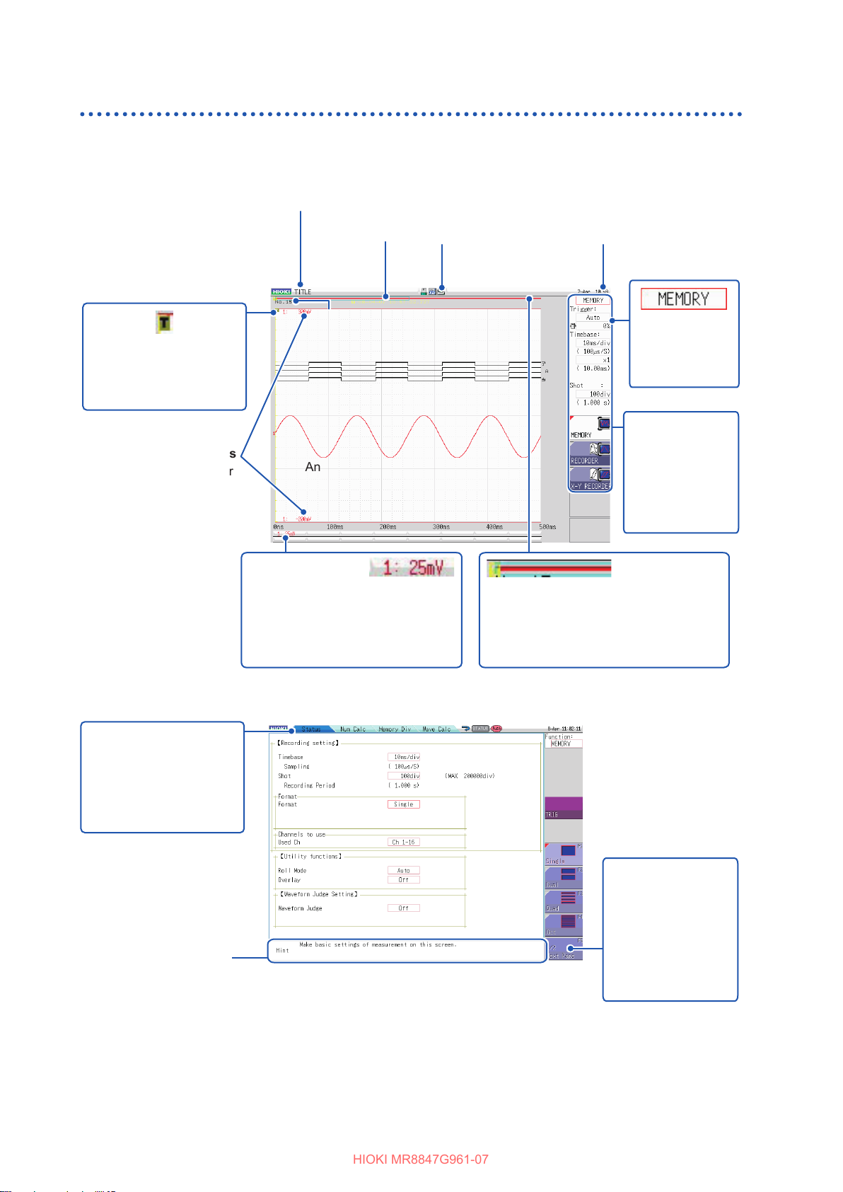
Screens Conguration
HIOKI MR8847G961-07
Explanation of screen contents
Waveform screen
Title comment
Shows a previously
entered title
comment.
(p. 160)
Trigger marker
Indicates the point when
the instrument triggered.
(p. 211)
Upper and lower limits
Shows upper and lower
limit values for each
channel. (p. 156)
Trigger time
Shows the date
and time when
the instrument
triggered.
(p. 211)
Storage counter
Shows the number of times the
instrument triggered. (p. 80)
Logic waveform (p. 76)
Analog waveform (p. 73)
Vertical axis display
Shows a value per division for each
channel linked to the range settings
of the vertical axis (voltage axis).
(p. 73)
Storage device icon
Displays the status of
storage devices.
(p. 47)
Current date and time
Shows the current date
and time in the manner
previously congured.
(p. 53)
Settings cursor
The present
cursor position
ashes.
Settings window
The window
used to congure
measurement
conditions.
(p. 60)
Scroll bar
The red bar indicates the waveform range
written in the memory. The blue frame
indicates the displayed waveform range.
(p. 146)
Items common to the Status, Channel, System, and File screens
Sheet tabs
Shows names of sheets
that can be selected.
Pressing each of the
MENU keys switches a
sheet to another.
Hint
Shows details about the item at the present settings cursor
position.
Messages such as “Online,” “Key Lock active.,” and error
messages also appear here.
Next Page button
Appears when more
than ve setting
items are available.
Pressing this button
switches other
groups of items to be
displayed.
22

1.4 Basic Key Operation
HIOKI MR8847G961-07
Press the CURSOR key and move the cursor to an item to be changed.
1
Cursor
GUI
Basic Key Operation
1
Overview
2
Check the illustrations on the GUI and press the function key (F key) to change the
settings.
The function assigned to the F key varies depending on the setting items.
To select an item to be set
Press the F key to change settings.
When there are more than six setting items, press the
F5 [Next Page] key to switch to the next page.
To increase and decrease a setting value
Increases a
numerical value at an
accelerated rate.
Decreases a numerical
value at an accelerated
rate.
Press the F key to change the setting value.
(Turning the jog dial or shuttle ring enables you
to change values.)
3
For some settings, press the CH.SET key to select [Exec], and press the TRIG.SET key
to select [Cancel].
To enter characters and numbers
See “8.1.3 Entering Alphanumeric Characters” (p. 163).
23
 Loading...