


LR8512
LR8513
LR8514
Instruction Manual
LR8515
WIRELESS PULSE LOGGER
WIRELESS CLAMP LOGGER
WIRELESS HUMIDITY LOGGER
WIRELESS VOLTAGE/TEMP LOGGER
Sept. 2018 Revised edition 6
LR8512B980-06 18-09H
EN


Contents
Introduction ........................................................................................1
Trademark ..........................................................................................1
Verifying Package Contents .............................................................2
Options ................................................................................................ 3
Safety Notes ....................................................................................... 5
Usage Notes ....................................................................................... 8
For customers who are using the LR8410 Wireless Logging
Station ..............................................................................................21
Instrument Version ..........................................................................22
1 Overview 23
1.1 Overview and Features .......................................................... 23
1.2 Parts Names and Functions .................................................. 24
1.3 DisplayCongurationExample ............................................26
2 Preparation for Measurements 29
2.1 Inspection Before Use ...........................................................29
2.2 Inserting/Replacing Batteries ...............................................30
Installation (Replacement)...............................................................31
Battery indicator display .................................................................32
Battery life indication ....................................................................... 33
2.3 Connecting the AC Adapter ...................................................35
2.4 Installing the Strap (optional) ...............................................36
2.5 Connecting Cables ................................................................. 37
Connecting the L1010 Connection Cable (LR8512) ...................... 37
Connecting the clamp sensor (LR8513) ......................................... 38
Connecting the temperature and humidity sensor (LR8514) ....... 48
LR8512B980-06
i

Contents
3 Using the LR8410 as a Unit 49
3.1 Real-time Measurement Using the LR8410 .......................... 49
Performing Real-time Measurement Using a Windows® PC
3.2
..50
4 Collecting Measurement Data Using a
®
Windows
4.1 SoftwareSpecications ......................................................... 51
System requirements ....................................................................... 51
Functionspecications ................................................................... 52
4.2 MeasurementWorkow .........................................................53
4.3 Installing the Software ........................................................... 55
Installation ........................................................................................55
Startup procedure ............................................................................ 56
Termination procedure ....................................................................56
Uninstallation ....................................................................................57
4.4 DisplayConguration ............................................................ 58
4.5 Basic Operation Procedure ................................................... 59
Operationow .................................................................................. 59
Selecting multiple wireless loggers ...............................................60
4.6 Registering/Deleting a Wireless Logger ..............................61
Registering a wireless logger .........................................................61
Deleting a wireless logger ............................................................... 64
Grouping wireless loggers .............................................................. 65
4.7 Setting Measurement Conditions .........................................67
Setting measurement ....................................................................... 68
Setting the channel .......................................................................... 70
Setting scaling (as needed) ............................................................. 81
Setting the alarm function (as needed) .......................................... 85
Setting the power saving function (as needed) .............................88
Setting the environment .................................................................. 89
Communications .............................................................................. 90
Copying the settings ........................................................................ 92
Initializing the settings .....................................................................93
PC 51
ii

Contents
4.8 Sending/Receiving the Setting Conditions .......................... 94
Sending the settings ........................................................................ 94
Receiving the settings ..................................................................... 95
4.9 Starting and Stopping Measurement and Monitoring ........96
Starting and stopping measurement .............................................. 96
Starting and stopping status monitoring ....................................... 97
Starting and stopping value monitoring ........................................ 98
4.10 Collecting Measurement Data ............................................... 99
Starting and stopping data collection ............................................ 99
4.11 Browsing/Analyzing Measurement Data ............................ 100
Browsing measurement data ........................................................ 100
Exportingmeasurementdata ........................................................ 101
Deleting measurement data ..........................................................103
4.12 Performing Wireless Logger Maintenance ........................104
Setting the clock.............................................................................104
Self-diagnosis ................................................................................. 105
Checking the version number ....................................................... 106
Updatingthermwareversion......................................................107
4.13 Convenient Functions .........................................................108
5 Collecting Measurement Data Using an
TM
Android
5.1 SoftwareSpecications ....................................................... 111
System requirements ..................................................................... 111
Functionspecications ................................................................. 111
5.2 MeasurementWorkow ....................................................... 112
5.3 Installing the Software ......................................................... 115
Installation ...................................................................................... 115
Startup procedure .......................................................................... 116
Uninstallation .................................................................................. 116
5.4 DisplayConguration .......................................................... 117
5.5 Registering/Deleting a Wireless Logger ............................122
Registering a wireless logger .......................................................122
Deleting a wireless logger ............................................................. 123
Terminal 111
iii

Contents
Grouping wireless loggers ............................................................ 124
5.6 Setting Measurement Conditions .......................................126
Setting measurement ..................................................................... 127
Setting the channel ........................................................................ 128
Advance settings............................................................................129
Initializing the settings ...................................................................130
5.7 Sending/Receiving the Setting Conditions ........................ 131
Sending the settings ...................................................................... 131
Receiving the settings ................................................................... 132
5.8 Starting and Stopping Measurement and Monitoring ......133
Starting and stopping measurement ............................................ 133
Starting and stopping monitoring ................................................134
5.9 Collecting Measurement Data ............................................. 136
Starting and stopping data collection .......................................... 136
5.10 Browsing/Analyzing Measurement Data ............................ 137
Browsing measurement data ........................................................ 137
Exportingmeasurementdata ........................................................ 139
Deleting measurement data ..........................................................142
5.11 Performing Wireless Logger Maintenance ........................143
Setting the clock.............................................................................144
Checking the version number ....................................................... 144
6 Specications 145
6.1 LR8512 Wireless Pulse Logger ........................................... 145
6.2 LR8513 Wireless Clamp Logger .........................................150
6.3 LR8514 Wireless Humidity Logger .....................................156
6.4 LR8515 Wireless Voltage/Temp Logger .............................161
6.5 Z2010, Z2011 Humidity Sensor ...........................................167
7 Maintenance and Service 169
7.1 Repair, Inspection, and Cleaning ........................................169
7.2 Troubleshooting ...................................................................171
7.3 ErrorDisplay ......................................................................... 173
iv

Contents
7.4 Disposal ................................................................................174
Removing lithium batteries ........................................................... 174
Appendix Appx.1
Measurement value recording ................................................Appx.1
Recording interval and recording time ..................................Appx.4
Target collection time ..............................................................Appx.4
Initial setting list ....................................................................... Appx.5
v

Contents
vi

Introduction
Introduction
Thank you for purchasing the HIOKI LR8512 Wireless Pulse Logger, LR8513 Wireless
Clamp Logger, LR8514 Wireless Humidity Logger, or LR8515 Wireless Voltage/Temp
Logger. To obtain maximum performance from the product, please read this manual
rst, and keep it handy for future reference.
In this manual, the name of each instrument is indicated as follows.
Product name Name indicated in the manual
LR8512 Wireless Pulse Logger
LR8513 Wireless Clamp Logger
LR8514 Wireless Humidity Logger
LR8515 Wireless Voltage/Temp Logger
There are the following instruction manuals available for this instrument. Please refer
to the appropriate manuals for the intended usage.
Read this rst.
Measurement Guide
For customers who use this instrument for the rst time, this
manual describes the basic operation procedures.
Instrument
Instruction Manual
(this manual)
Describes details of the functions, operations, and specications
of this instrument.
Trademark
• Microsoft and Windows, Windows Vista, Microsoft Excel are either registered
trademarks or trademarks of Microsoft Corporation in the United States and other
countries.
• Bluetooth
The trademark is used by HIOKI E.E. CORPORATION under license.
• Adobe and Adobe Reader are either trademarks or registered trademarks of Adobe
Systems Incorporated in the United States and other countries.
• Android and Google Play are trademarks of Google, Inc.
®
is a registered trademark of Bluetooth SIG, Inc. (USA).
1
Verifying Package Contents
Verifying Package Contents
• When you receive the instrument, inspect it carefully to ensure that no damage
occurred during shipping. In particular, check the accessories, panel keys,
and connectors. If damage is evident, or if it fails to operate according to the
specications, contact your authorized Hioki distributor or reseller.
Check the package contents as follows.
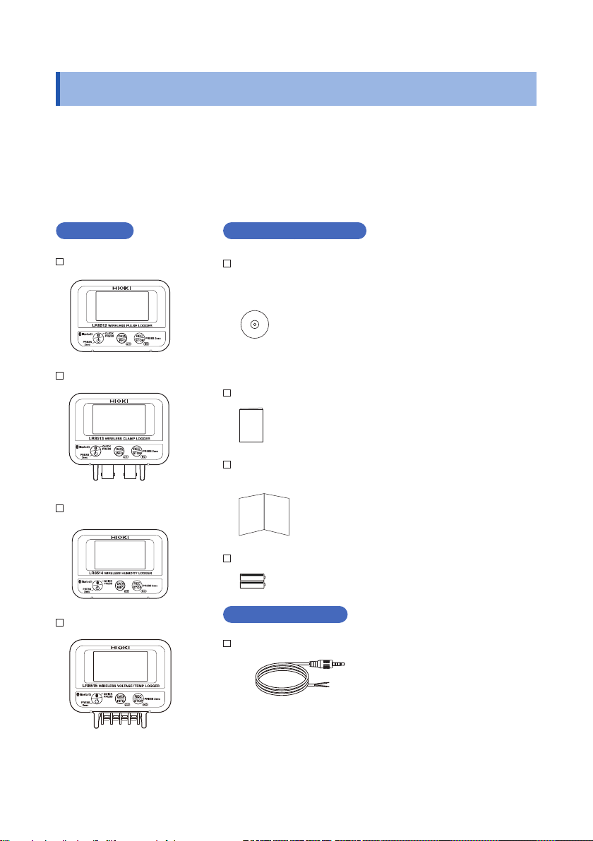
Instrument
LR8512 × 1
LR8513 × 1
LR8514 × 1
LR8515 × 1
Common accessories
CD × 1
[Instruction Manual (PDF), Application Software (Logger
Utility, Wireless Logger Collector)]
The latest version of the application software can be
downloaded from our website.
Measurement Guide
Precautions Concerning Use of Equipment That Emits
Radio Waves
LR6 Alkaline battery × 2
LR8512 Accessory
L1010 Connection Cable (length approx. 1.5 m) × 2
2

Verifying Package Contents
Options
The following options are available for the LR8512, LR8513, LR8514, and LR8515.
Contact your authorized Hioki distributor or reseller when ordering.
Common options
Z2003 AC Adapter (power cord attached)
Z5004 Magnetic Strap
Z5020 Magnetic Strap
LR8512 Option
L1010 Connection Cable (length approx. 1.5 m)
LR8513 Option
9669 Clamp On Sensor
9695-02 Clamp On Sensor
CT6500 Clamp On Sensor
9657-10 Clamp On Leak Sensor
9675 Clamp On Leak Sensor
CT9691-90 Clamp On AC/DC Sensor
CT9692-90 Clamp On AC/DC Sensor
CT9693-90 Clamp On AC/DC Sensor
9219 Connection Cable (for 9695-02 connection)
CT7631 AC/DC Current Sensor
CT7636 AC/DC Current Sensor
CT7642 AC/DC Current Sensor
CT7731 AC/DC Auto-Zero Current Sensor
CT7736 AC/DC Auto-Zero Current Sensor
CT7742 AC/DC Auto-Zero Current Sensor
CT9667-01 AC Flexible Current Sensor
CT9667-02 AC Flexible Current Sensor
CT9667-03 AC Flexible Current Sensor
CT7044 AC Flexible Current Sensor
CT7045 AC Flexible Current Sensor
CT7046 AC Flexible Current Sensor
CM7290 Display Unit
For the CT7631,CT7636,CT7642,CT7731,CT7736,CT7742,CT7044,CT7045,CT7046
CM7291 Display Unit
For the CT7631,CT7636,CT7642,CT7731,CT7736,CT7742,CT7044,CT7045,CT7046
L9095 Output Cord (for CM7290/CM7291 connection)
3

Verifying Package Contents
LR8514 Option
Z2010 Humidity Sensor (Length including the sensor: Approx. 50 mm)
Z2011 Humidity Sensor (Cable length: Approx. 1.5 m)
Supported instrument
LR8410 Wireless Logging Station
(Supported for software version 1.30 and later)
4

Safety Notes
Safety Notes
This instrument is designed to conform to IEC 61010 Safety Standards, and has been
thoroughly tested for safety prior to shipment. However, using the instrument in a way
not described in this manual may negate the provided safety features.
Before using the instrument, be certain to carefully read the following safety notes.
DANGER
Mishandling during use could result in injury or death, as well as damage
to the instrument. Be certain that you understand the instructions and
precautions in the manual before use.
WARNING
If you do not have knowledge or experience of electrical measurements,
use this instrument under supervision of experienced personnel.
Notation
In this manual, the risk seriousness and the hazard levels are classied as follows.
DANGER
WARNING
CAUTION
IMPORTANT
Windows
Dialog Windows dialog boxes are referred to as dialogs.
[ ]
Indicates an imminently hazardous situation that will result in death or
serious injury to the operator.
Indicates a potentially hazardous situation that may result in death or
serious injury to the operator.
Indicates a potentially hazardous situation that may result in minor
or moderate injury to the operator or damage to the instrument or
malfunction.
Indicates information related to the operation of the instrument or
maintenance tasks with which the operators must be fully familiar.
Indicates a strong magnetic-eld hazard.
The effects of the magnetic force can cause abnormal operation of
heart pacemakers and/or medical electronics.
Indicates prohibited actions.
Indicates an action that must be performed.
Additional information is presented below.
Windows XP, Windows Vista, Windows 7, Windows 8 and Windows
10 are referred to as ″Windows″, otherwise specied.
The names and keys on the screen including menus, commands,
dialogs, dialog button names, etc. are enclosed in brackets [ ].
5
Safety Notes
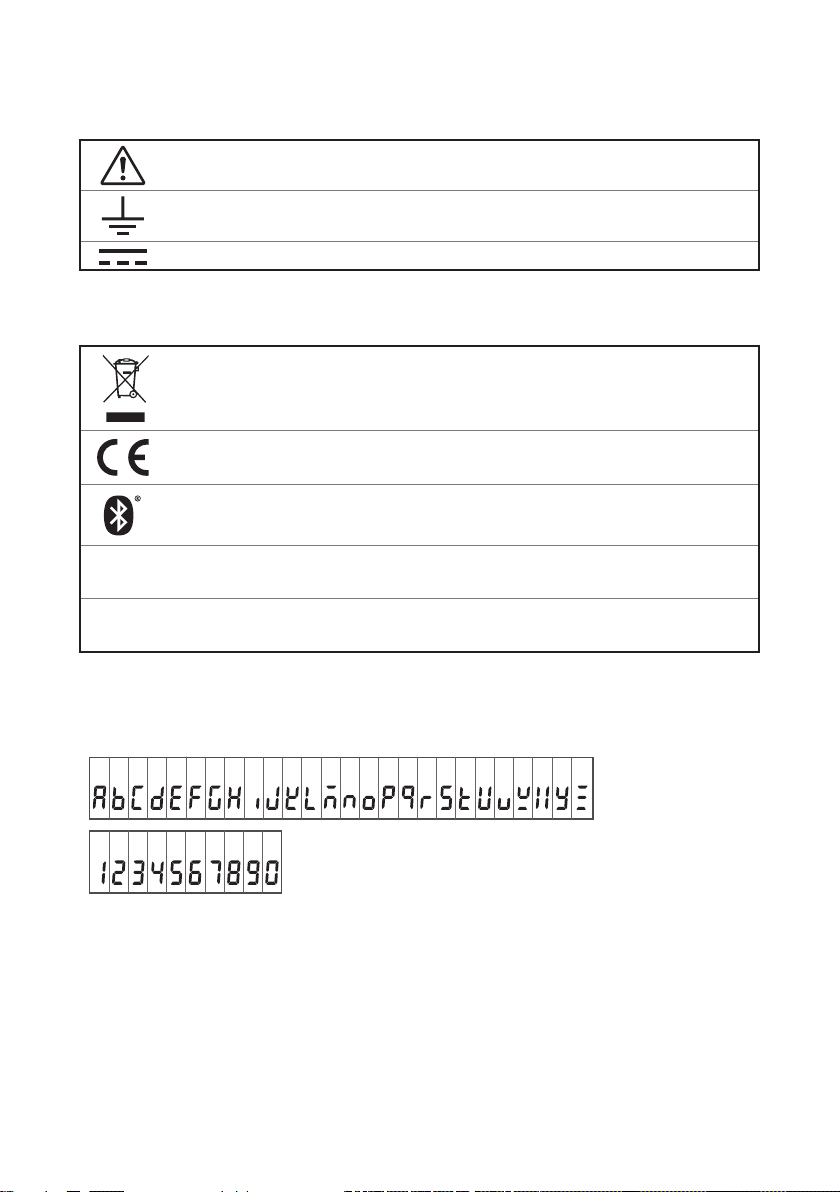
Symbols afxed to the instrument
Indicates cautions and hazards. When the symbol is printed on the instrument,
refer to a corresponding topic in the Instruction Manual.
Indicates a grounding terminal.
Indicates DC (Direct Current).
Symbols for various standards
Indicates the Waste Electrical and Electronic Equipment Directive (WEEE
Directive) in EU member states.
Indicates that the product conforms to regulations set out by the EU Directive.
Indicates that the product incorporates Bluetooth® wireless technology.
FCC ID
Indicates the ID number of the wireless module certied by the U.S. Federal
Communications Commission (FCC).
Indicates the identication number of a wireless module approved by Industry
IC
Canada (IC).
Screen display
The instrument screen displays the alphanumeric characters as follows.
A B C D E F G H I J K L M N O P Q R S T U V W X Y Z
1 2 3 4 5 6 7 8 9 0
6

Safety Notes
Accuracy
We dene measurement tolerances in terms of rdg. (reading) and dgt. (digit) values,
with the following meanings:
(Maximum display value or scale length/range)
f.s.
rdg.
dgt.
The maximum displayable value or scale length. This is usually the name of
the currently selected range.
(Reading or displayed value)
The value currently being measured and indicated on the measuring
instrument.
(Resolution)
The smallest displayable unit on a digital measuring instrument, i.e., the input
value that causes the digital display to show a “1” as the least-signicant digit.
Measurement categories
To ensure safe operation of measuring instruments, IEC 61010 establishes safety
standards for various electrical environments, categorized as CAT II to CAT IV, and
called measurement categories.
DANGER
• Using a measuring instrument in an environment designated with
a higher-numbered category than that for which the instrument
is rated could result in a severe accident, and must be carefully
avoided.
• Using a measuring instrument without categories in an environment
designated with the CAT II to CAT IV category could result in a
severe accident, and must be carefully avoided.
CAT II: When directly measuring the electrical outlet receptacles of the primary
electrical circuits in equipment connected to an AC electrical outlet by a
power cord (portable tools, household appliances, etc.)
CAT III: When measuring the primary electrical circuits of heavy equipment (xed
installations) connected directly to the distribution panel, and feeders from
the distribution panel to outlets
CAT IV: When measuring the circuit from the service drop to the service entrance,
and to the power meter and primary overcurrent protection device
(distribution panel)
Distribution panel
Service entrance
CAT III
CAT I I I
Internal wiring
CAT II
CAT I I
T
Outlet
Service drop
CAT IV
CAT I V
Power meter
Fixed installation
7

Usage Notes
Usage Notes
Follow these precautions to ensure safe operation and to obtain the full benets of
the various functions.
Bluetooth
This instrument and the LR8410 use radio waves of a band frequency of 2.4 GHz.
No radio station license is required to use this product, however, be aware of the
following.
®
WARNING
• Do not use this instrument in a system that requires high safety and
reliability.
• Do not use this instrument near any medical equipment, such as a
pacemaker, etc.
• Do not modify, disassemble, or repair the instrument.
CAUTION
• If this instrument is used near any equipment that uses the same
frequency band, such as wireless LAN equipment, etc., communications
may become unstable or other equipment may be affected.
• The line-of-sight distance between the instrument and the LR8410 is 30
m. If there is an obstacle (wall, metal screen, etc.), communications may
become unstable or the communications distance may become shorter.
• Communications between the instrument and the LR8410 are encrypted
by SSP, however, the condentiality of any information is not guaranteed.
We are not responsible for any leakage of measurement data by wireless
communications.
• This instrument and the LR8410 generate electric waves. Usage of
electric waves requires permission and authorization in each country.
Using electric waves in any country or region other than the ones listed
in the attached document “Precautions Concerning Use of Equipment
That Emits Radio Waves” is against the law and may be subject to
punishment.
When the instrument is positioned on a stand instead of directly on the oor,
communications can become more stable.
8

Usage Notes
Check before use
Verify that it operates normally to ensure that no damage occurred during storage or
shipping. If you nd any damage, contact your authorized Hioki distributor or reseller.
Installation
WARNING
Installing the instrument in inappropriate locations may cause a
malfunction of the instrument or may give rise to an accident. Avoid
the following locations.
• Exposed to direct sunlight or high temperature
• Exposed to corrosive or combustible gases
• Exposed to water, oil, chemicals, or solvents
• Exposed to high humidity or condensation
• Exposed to a strong electromagnetic eld or electrostatic charge
• Exposed to high quantities of dust particles
• Near induction heating systems (such as high-frequency induction
heating systems and IH cooking equipment)
• Susceptible to vibration
For details on the operating temperature and humidity, see the
specications.
CAUTION
• This instrument is not drip-proof. Water that drips on the connector could
cause a malfunction.
• Do not allow any condensation to form. Condensation can form
particularly in an environment where the temperature changes drastically.
• Do not allow the instrument to become wet or take measurements with
wet hands. Doing so may cause a malfunction.
• Do not position the instrument on an unstable table or inclined surface.
When the instrument falls or tips, an injury or malfunction can occur.
Install the LR8515 Wireless Voltage/Temp Logger with attention to the following:
• Take appropriate measures to prevent the ambient temperature near the terminal
block from changing. Install the instrument where it is not exposed to direct air
from a ventilation fan, air conditioner, etc. A measurement error can occur during
thermocouple input.
• When the instrument is moved to a location with a signicant temperature
change, wait for at least 60 minutes before starting measurement.
9

Usage Notes
Handling of this instrument
CAUTION
Avoid any vibration or impact to prevent damage to the instrument during
transportation and handling. Be especially careful regarding the impact by
a fall.
This instrument may cause interference if used in residential areas. Such use must
be avoided unless the user takes special measures to reduce electromagnetic
emissions to prevent interference to the reception of radio and television broadcasts.
Handling of cords and cables
WARNING
Make sure to use the specied power cord when using the instrument.
Otherwise, a re may be caused.
CAUTION
• Avoid stepping on or pinching the cables to prevent damage to the
cables. Do not bend or pull the cables.
• To prevent any wires from breaking, pull on the connector end, not the
cable, to disconnect the output connector.
• To prevent any wires from breaking, pull on the connector end, not the
cord, to disconnect the power cord from the outlet or the instrument.
• The cables become stiff below 0°C. If the cables are bent or pulled in this
condition, the cable insulation may be damaged or the wires may be cut.
•
When using the instrument, make sure to use the connection cable specied by our
company. When any other cable is used, it may not be possible to perform accurate
measurement due to a contact failure, etc.
• When a measurement cable that is longer than 3 m is connected, measurement
may be affected by factors in the EMC environment, such as exogenous noise.
• Position the measurement cable away from the power line or ground cable.
• When the measurement cable is connected in parallel to other equipment,
measurement values may vary. If the measurement cable is to be connected in
parallel, make sure to check the operation before use.
10

Usage Notes
Before turning on the power
CAUTION
• When operating the instrument using a UPS (uninterruptible power
supply) or DC-AC inverter, do not use any square-wave and pseudo sinewave UPS or DC-AC inverter. Doing so may damage the instrument.
• Make sure that the power voltage connection is correct. Connection
errors could damage the internal circuit.
The instrument and measurement unit will not fail due to a momentary power
failure under 40 ms. If the power failure is longer than 40 ms, the power may be
shut off temporarily. Install the instrument in consideration of power conditions at
the installation location.
Magnet of the optional strap
DANGER
Those with medical electronics such as pacemakers should not use
the Z5004/Z5020 Magnetic Strap. Nor should such persons approach
the Z5004 or Z5020. It is extremely dangerous. The electronics may
not operate properly and the life of the operator may be put at great
risk.
WARNING
Swallowing magnets could be life-threatening. Keep any magnets
out of reach, especially of small children. If you accidentally swallow
magnets, immediately seek medical attention.
CAUTION
• Do not use the Z5004 or Z5020 in locations where it may be exposed to
rainwater, dust, or condensation. In those conditions, the magnet may be
decomposed or deteriorated. The magnet adhesion may be diminished.
In such case, the instrument may not be hung in place and may fall.
• Do not bring the Z5004 or Z5020 near magnetic media such as oppy
disks, magnetic cards, pre-paid cards, or magnetized tickets. Doing so
may corrupt and may render them unusable. Furthermore, if the Z5004
or Z5020 is brought near precision electronic equipment such as PCs, TV
screens, or electronic wrist watches, they may fail.
• Keep magnets away from any impact by a fall. The magnets may chip or
crack due to impact.
11

Usage Notes
AC adapter
• Make sure to use the optional Z2003 AC Adapter. The rated power
voltage for the AC adapter is 100 V to 240 V AC and the rated
power frequency is 50 Hz/60 Hz. Do not use the AC adapter at any
voltage other than the above to avoid damage to the instrument and
electrical accidents.
• Before turning on the power, make sure that the power voltage
indicated on the AC adapter matches the power voltage to be used.
Using the AC adapter outside the specied power voltage range
could cause damage to the instrument or AC adapter or electrical
accidents.
• Connect the output plug to the instrument and then connect the plug to
an outlet. Connecting the energized output plug to the instrument may
damage the instrument.
• When connecting an external power supply, connect the output plug to
the instrument and then supply external power.
Handling of batteries
WARNING
CAUTION
12
WARNING
• Do not short circuit, disassemble, or incinerate batteries. Do not
charge alkaline batteries. Doing so may cause an explosion. Handle
and dispose of batteries in accordance with local regulations.
• In order to prevent electric shocks, remove measurement cables
and then replace the batteries.
• After battery replacement, reattach and screw down the battery
cover before use.
• To prevent damage to the instrument or electric shocks, make sure
to use the battery cover screw (screw with a spring) that is attached
at the time of shipment. If you lose the screw or spring or nd any
damage, contact your authorized Hioki distributor or reseller.

Usage Notes
CAUTION
Poor performance or damage from battery leakage could result. Observe
the cautions listed below.
• Do not mix new and old batteries, or different types of batteries.
• Be careful to observe the battery polarity during installation. Poor
performance or damage from battery leakage could result.
• Do not use batteries after their recommended expiry date.
• Do not allow used batteries to remain in the instrument.
• To avoid corrosion from battery leakage and/or damage to the instrument,
remove the batteries from the instrument if it is to be kept in storage for
an extended period.
IMPORTANT
The displayed remaining battery level may be different from the actual remaining
battery level due to the battery characteristics, settings during use, temperature or
consumption level. When a battery is used in a low temperature environment or
a weak and deteriorated battery is used, the power may shut off regardless of the
battery indicator display.
Batteries
The battery indicator display and battery life are based on the use of a new alkaline
battery.
Use of nickel-metal hydride batteries
When nickel-metal hydride batteries are used, the battery indicator display does
not operate correctly.
The battery life varies depending on the capacity, charging condition, deterioration
due to repeated use, etc. Use batteries in consideration of the factors above.
Use of manganese dioxide batteries
Do not use manganese dioxide batteries as the instrument may not be able to
measure or communicate.
13

Usage Notes
Wire connection
Do not permanently connect the instrument in an environment where
there is a possibility of surges exceeding the dielectric withstand voltage.
Doing so may damage the instrument and result in personal injury.
• Do not allow input that exceeds the maximum rating. Doing so may
cause heat to generate, which can cause damage to the instrument,
short circuits or electric shocks.
• Do not connect any equipment other than the specied clamp
sensor to the LR8513 Wireless Clamp Logger. Doing so may cause
electric shocks or damage to the instrument.
• Do not connect any equipment other than the specied temperature
and humidity sensor to the LR8514 Wireless Humidity Logger.
Doing so may cause electric shocks or damage to the instrument.
• A semiconductor relay is used to isolate between the input
terminals and channel of the LR8515 Wireless Voltage/Temp Logger.
When any voltage that exceeds the specied rating is applied, the
semiconductor relay can fail with a short-circuit. Never input any
voltage that exceeds the specied rating. Especially be aware of
lightning surges. If there is an error in measurement values, send
the instrument for repair.
• Do not connect the measurement cable to the instrument while it
is connected to the object to be measured. Doing so may cause
electric shocks.
• The analog input terminal maximum input voltage, maximum rated
voltage to earth, and maximum rated voltage between the input
terminals and channel of each logger is shown in the following
table. To avoid electric shocks and damage to the instrument, do
not input any voltage over the voltages shown below.
DANGER
WARNING
14
Model
LR8512 0 to 50 V DC
LR8515 ±50 V DC
Maximum
input voltage
Maximum rated voltage
to earth
30 V AC rms or 60 V DC
(between each analog
input channel and chassis)
30 V AC rms or 60 V DC
(between each analog
input channel and chassis)
Maximum rated
voltage between
input terminals
and channel
Non-isolated
(GND common)
60 V DC

Usage Notes
WARNING
The power supply ground and input terminals (-) are common and
not isolated. When using an external power supply, use an isolated
external power supply or connect the wires so that there is no
potential difference between the ground of the external power supply
and the object to be measured to prevent damage to the instrument or
electric shocks.
Handling of CD
• Do not allow any dirt or scratches on the disk recording surface. When writing on
the label face, use a pen with a soft tip.
• Store the disk in a protective case and do not expose the disk to direct sunlight
or high temperatures and humidity.
• We are not responsible for any trouble in the Windows
this disk is used.
®
computer system when
15

Usage Notes
Handling of clamp sensor
Connect the clamp sensor to the LR8513 and then to the live
measurement wire. Observe the following to avoid short circuits and
electric shocks.
• When the clamp sensor is opened, do not allow the metal part of
the clamp to short between the 2 wires, and do not use it over bare
conductors.
• Use the clamp sensor in a circuit below the following voltage values.
Do not use over bare conductors.
Model name Clamp sensor Clamp sensor
9669
9695-02 CAT III 300 V AC
CT6500 CAT III 600 V AC
9657-10
9675
CT9691-90
CT9693-90
CT7631
CT7636
CT7642
CT7731
CT7736
CT7742
CT9667-01
CT9667-02
CT9667-03
CT7044
CT7045
CT7046
DANGER
CAT III 600 V AC
Clamp On Sensor
Clamp On Leak Sensor CAT III 300 V AC
Clamp On AC/DC Sensor
AC/DC Current Sensor
AC/DC Auto-Zero
Current Sensor
AC Flexible Current Sensor
CAT III 600 V AC/DCCT9692-90
CAT IV 600 V AC/DC
CAT IV 600 V AC/DC
CAT III 1000 V AC/DC
CAT IV 600 V AC/DC
CAT IV 600 V AC/DC
CAT III 1000 V AC/DC
CAT IV 600 V AC/DC
CAT III 1000 V AC/DC
16

Usage Notes
DANGER
• Do not allow the clamp sensor to touch beyond a barrier.
• The maximum input current of the clamp sensor is as follows. (At 45
to 66 Hz)
Model name Clamp sensor Maximum input current
9669
9695-02 60 A
CT6500 600 A
9657-10
9675 10 A
CT9691-90
CT9692-90 200 A
CT9693-90 2000 A
CT7631
CT7636 600 A
CT7642 2000 A
CT7731
CT7736 600 A
CT7742 2000 A
CT9667-01
CT9667-02 10000 A
CT9667-03 10000 A
CT7044
CT7045
CT7046
Clamp On Sensor
Clamp On Leak Sensor
Clamp On AC/DC Sensor
AC/DC Current Sensor
AC/DC Auto-Zero
Current Sensor
AC Flexible Current Sensor
1000 A
30 A
100 A
100 A
100 A
10000 A
1000A(600A range)
10000A(6000A range)*
Supplying a current in excess of the maximum input may damage
the instrument and result in personal injury.
*Range changes are controlled from the CM7290/CM7291
• Make sure to connect the clamp sensor to the secondary side of
the breaker. The secondary side of the breaker is protected by
the breaker even if a short-circuit occurs. Do not measure on the
primary side as it has a large current capacity, and signicant
damage is caused when a short-circuit occurs.
17
Usage Notes
WARNING
• This instrument measures live wires. To avoid electric shocks when
measuring live wires, wear appropriate protective gear, such as
insulated rubber gloves, boots and a safety helmet.
• To avoid electric shocks, disconnect the clamp from the object to be
measured, open the cover, and then replace the batteries.
• After battery replacement, reattach and screw down the battery
cover before use.
• To avoid electric shocks, do not approach high-voltage equipment
or wiring when measuring the Class B ground cable for a
transformer. When the ground cable is close to a high-voltage live
part and it is difcult to measure, change the route of the ground
cable before measurement. (When the 9657-10, 9675 Clamp On Leak
Sensor is used)
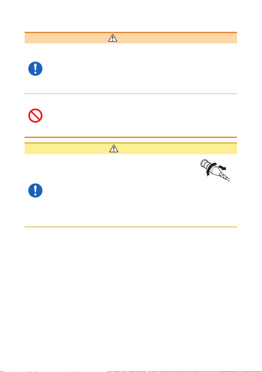
CAUTION
• To prevent damage to the BNC connector, make
sure to release the lock and then pull on the
connector end of the BNC connector.
• Close the clamp core when it is not used. When the clamp core remains
open, dust collects on the butt joint of the core, which can cause a
malfunction.
• If the screw of the output terminal for the 9695-02 Clamp On Sensor is
lost, purchase the “M3 screw with spring washer × 5”. Using any screw
other than the above can cause damage to the clamp sensor.
18
Usage Notes
CAUTION
• Do not excessively tighten the screw of the output terminal for the 9695-
02 Clamp On Sensor. The appropriate torque is 0.5 N•m.
• Do not input current exceeding the specied measurement range. Doing
so may damage the instrument.
• Avoid stepping on or pinching the cords to prevent damage to them. Do
not bend or pull the cord bases.
• Do not drop or hit the clamp sensor. Doing so can damage the core butt
joint and negatively affect measurement.
• Do not tuck foreign material into the joint of the clamp core tip and
instrument or insert an object into the gap of the core. Doing so may
deteriorate the sensor characteristics or cause an open/close operation
failure.
• To avoid damaging the instrument, do not connect any equipment other
than the clamp sensor to the BNC terminal.
• To avoid damaging the instrument, do not short the connector or input
voltage.
• When dust is attached to the clamp core tip butt joint, gently wipe it with a soft
cloth to prevent adverse effects on measurement.
• When connecting a cable to the output terminal of the 9695-02 Clamp On
Sensor, bring the cable as close to the terminal as possible to avoid the inuence
of an external magnetic eld.
• When connecting the 9695-02 Clamp On Sensor to the instrument, use the 9219
Connection Cable. (The 9219 connection is “Crimped terminal-BNC”.)
19
Usage Notes
Handling of temperature and humidity sensor
CAUTION
• The temperature and humidity sensor is not dustproof or waterproof. Do
not use the sensor in locations where it may be exposed to dust or water.
It may cause a malfunction of the instrument.
• The temperature and humidity sensor is not drip-proof. Water that drips
onto the connector could cause a malfunction.
• Sensor sensitivity and precision will degrade over time, even under normal
operating conditions. To maintain the instrument’s ability to make measurements
that conform to the accuracy specications, it is recommended to replace the
temperature and humidity sensor with a new unit once it has been used for one
year after being opened.
• When the sensor is used outside the specied operating (storage) environment,
the sensor accuracy may deteriorate even within the 1 year accuracy warranty
period and accurate measurement cannot be performed.
• In principle, the surface of the instrument’s temperature and humidity sensor
may become contaminated if exposed to an environment containing organic
gases (ketone, acetone, ethanol, toluene, etc.), increasing the error component
of humidity measurement.
• Do not expose the temperature and humidity sensor to any concentrated
chemical solvent for an extended period of time while it is used or stored.
• The sensor may become contaminated by organic gases released from some
types of vinyl chloride and packaging material.
• When the temperature and humidity sensor is not used, place it with a drying
agent in a plastic bag, seal the bag completely, and store it in a cool, dark place.
• Do not allow any condensation to form. Condensation can form particularly in
any environment where the temperature changes drastically.
• This instrument does not come with a guarantee against any problem when the
sensor is used outside the specied operating (storage) environment.
• Due to a humidity change (from low to high humidity or high to low humidity),
up to ±1% RH of change (hysteresis) occurs in the measured humidity value.
Precautions during shipment
• To avoid damaging the instrument, remove accessories and options from
the instrument.
• Avoid any vibration or impact to prevent damage to the instrument,
humidity sensor, and clamp sensor during transportation and handling.
Be careful especially with impact by a fall.
20
CAUTION
For customers who are using the LR8410 Wireless Logging Station
For customers who are using the LR8410
Wireless Logging Station
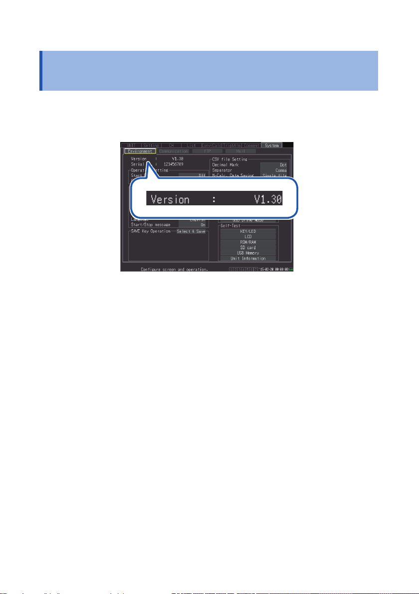
This instrument can be used on the LR8410 rmware version 1.30 or later.
The rmware version for the LR8410 is displayed on the system screen.
The latest version can be downloaded from our website.
For details on how to upgrade the software, see our website or check with your authorized Hioki
distributor or reseller.
21
Instrument Version
Instrument Version
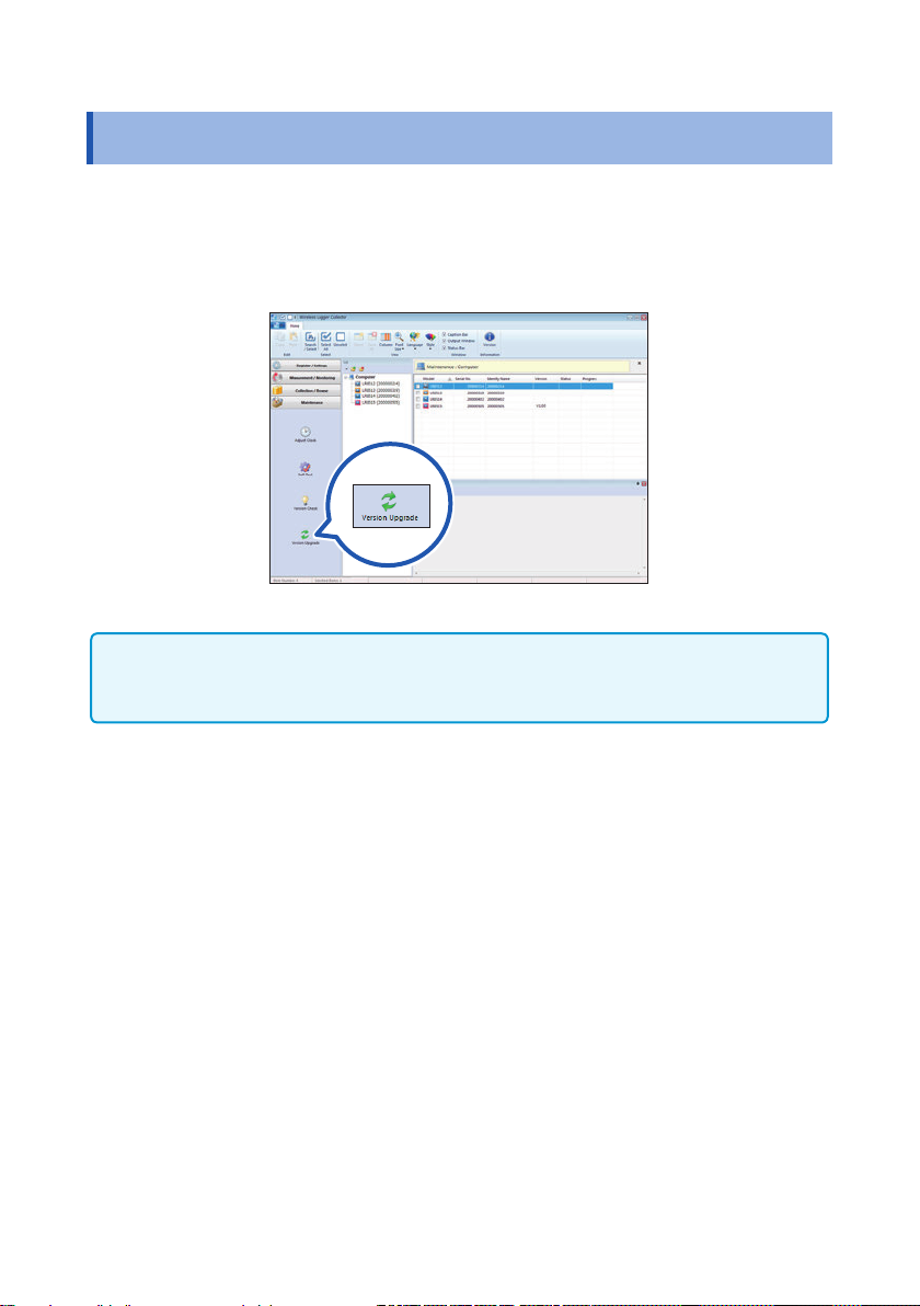
The Wireless Logger Collector can be used on the instrument software version 1.20
or later.
A version older than 1.20 needs to be updated. The software can be updated in
Wireless Logger Collector (Windows
If the software version is older than 1.20, a communication error (protocol error)
occurs in any communications attempted between the instrument and Wireless
Logger Collector.
®
PC version). (p. 107)
22
 Loading...