

Page 1
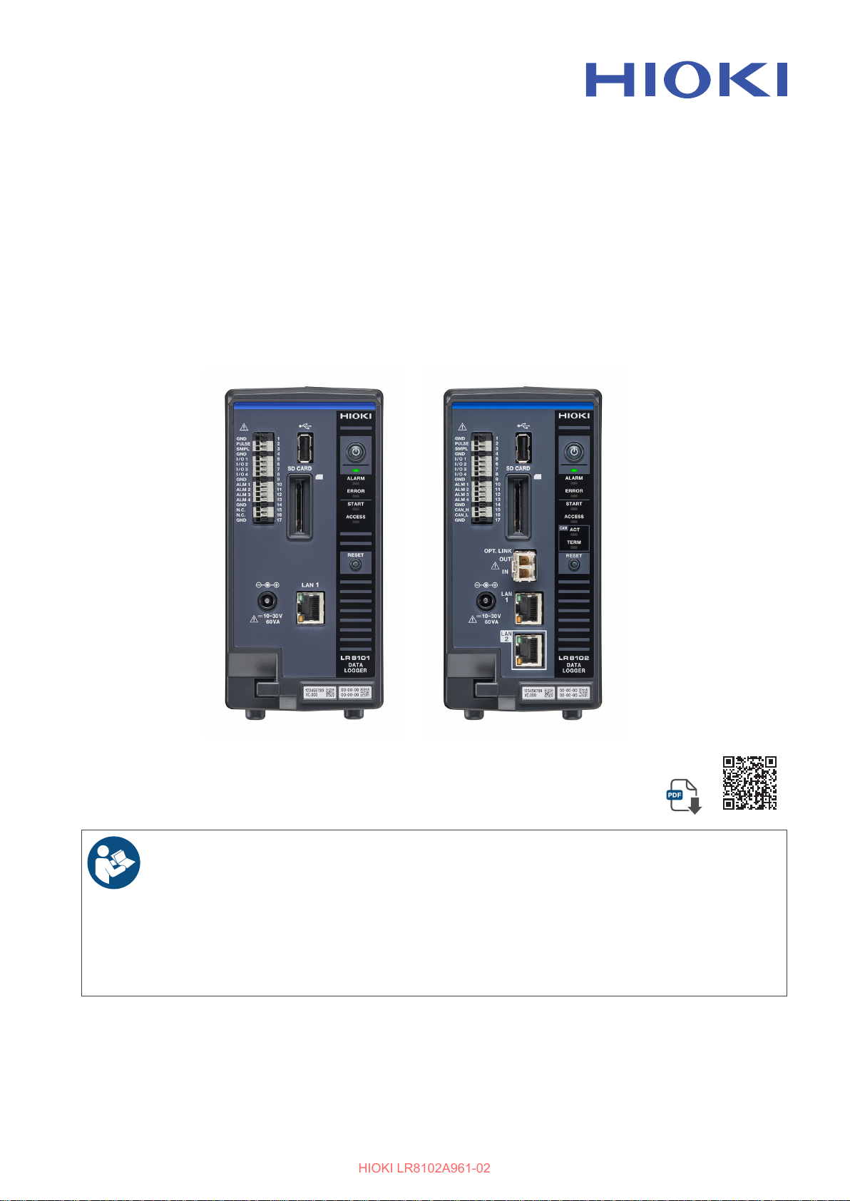
LR8101
HIOKI LR8102A961-02
LR8102
DATA LOGGER
Instruction Manual
Read carefully before use.
Keep for future reference.
Safety Information
Part Names and Functions
Settings and Operations
Feb. 2025 Revised edition 2
LR8102A961-02
Check for the latest edition and
other language versions.
p.11 Maintenance and Service p.455
p.32 Error messages
p.101
[600659722]
p.458
EN
Page 2

Page 3

Contents
HIOKI LR8102A961-02
Introduction
Symbols and Abbreviations
Checking Package Contents
Safety Information
Usage Notes
About This Manual
Communication Method
.................................................. 7
......................... 8
..................... 10
Options (sold separately)
........................11
......................................11
.............................................. 13
..................................... 19
............................. 20
Command
Message format
Command syntax
Header
Message terminator
Separator
Data part
Abbreviation of combined command
header
Output queue and input buer
Register
Items to be initialized to the default status
........................................... 20
................................... 21
................................. 22
............................................... 22
.............................. 23
............................................ 23
............................................ 24
................................................ 26
................ 27
.............................................. 27
29
1 Overview 31
1.1 Product Overview and Features
Both LR8101 and LR8102
LR8102 only
........................................ 31
..................... 31
1.2 Part Names and Functions
LR8101 and LR8102 Data Loggers
1.3 Options
M7100, M7102 Voltage/Temp Module
M7103 Power Measurement Module
M1100 AC Power Module
Other options
1.4 Measurement Workow
............................................. 35
...................... 38
....................................... 39
.................... 43
....... 31
............... 32
......... 32
...... 35
....... 36
2 Connection
(Preparation for
Measurements)
2.1 Inspection Before Use
2.2 Connecting the Measurement
Modules
2.3 Connecting the AC adapter
2.4 Connecting an External Power
Supply
............................................ 46
.............................................. 50
45
...................... 45
.............. 48
2.5 Connecting the AC Power Supply
Module
2.6 Connecting Cables
Wiring the voltage cable and
thermocouple
Wiring for the pulse input
Wiring for the alarm output
Wiring for external control
Wiring for the external sampling
Wiring the CAN cable (LR8102 only)
Wiring the optical connection cable
(LR8102 only)
Connecting the voltage cords
Connecting the current sensor (current
input)
When a value exceeds the
measurement range (VT/CT is used)
2.7 Turning ON and OFF the Power
............................................. 51
........................... 54
...................................... 56
....................... 59
..................... 60
...................... 61
.............. 62
....... 63
...................................... 65
................. 67
................................................. 68
....... 70
...... 71
2.8 SD Memory Card and USB Drive
Installing and removing an SD memory
card
................................................... 74
Installing and removing a USB drive
........ 75
2.9 Wiring the Power Measurement
Module to the Measurement Line
Setting the wiring mode and current
sensor
................................................ 76
Current sensor automatic detection
function
Current sensor phase compensation
Zero adjustment and degaussing (DMAG)
Wiring to the measurement line
Connection diagram
Checking connection
2.10 Setting and Connecting the LAN
Network settings on PC
Connecting the instrument and a PC via
LAN
Default connection settings for LAN1
.............................................. 77
....... 79
.............. 82
............................. 83
............................ 84
...... 85
......................... 88
................................................... 95
....... 97
3 Settings and
Operations
3.1 Controlling the Instrument Using
Communication Commands
Standard commands specied by IEEE
488.2
............................................... 102
3.2 Basic Operations and Queries
3.3 Setting Measurement Conditions
101
........... 101
....... 105
..... 72
..... 76
81
... 106
LR8102A961-02
3
Page 4

Contents
HIOKI LR8102A961-02
Normal sampling
External sampling
Common settings for the recording
modes
...............................................110
Set the synchronized terminal
Data refresh interval of the
measurement modules
................................ 106
............................... 109
...............113
.........................115
3.4 Setting the Voltage/Temp Module
Voltage measurement
Temperature (thermocouple)
measurement
.................................... 122
......................... 120
3.5 Setting the Power Measurement
Module
Setting the power measurement range
Synchronization source
Low-pass lter (LPF)
Zero cross lter and measurement lower
limit frequency (measurable frequency
range setting)
Rectication method
Scaling (when VT (PT) or CT is used)
Zero suppression
Count mode for integration
measurement
Enabling the harmonic measurement
Setting the details for harmonic
measurement
Averaging function
Delta conversion function
Power formula
Selecting the power calculation channel
Power calculation channel list
Status
Starting simple measurement (for the
M7103 Power Measurement Module)
........................................... 126
...................... 129
........................... 131
.................................... 132
........................... 133
............................... 135
.................................... 135
.................................... 139
.............................. 141
.................... 142
................................... 144
.............. 145
.............................................. 149
3.6 Conguring the Pulse Channel
and Logic Channel Settings
Pulse aggregation
Rotation speed measurement
Logic signal measurement
.............................. 152
3.7 Using the Scaling Function
3.8 Entering Comments
Title comment
Channel comment
Module identication name
.................................... 168
....................... 168
.............................. 168
3.9 Performing Zero Adjustment
........... 152
.............. 155
................... 159
............ 161
.................. 169
.......... 170
3.10 Starting and Stopping
Measurement
Forcing termination of measurement
................................. 171
..... 172
.. 120
.. 126
.... 134
.... 136
. 144
.... 151
Handling of data exceeding the
allowable measurement range
Measurement operation status change
.............. 173
.. 173
3.11 Checking Measurement Start Time
and Trigger Time
............................ 174
4 Acquiring
Measurement Data
4.1 Acquiring Measurement Data on
Internal Memory
4.2 Acquiring Realtime Data
4.3 Acquiring Hold Data
4.4 Conversion of Measurement Data
4.5 About Binary Data
4.6 Text (Physical Value)
4.7 Comparison of Realtime Data
Acquisition
............................. 176
....................... 182
.......................... 187
...................... 188
...................................... 189
175
................ 180
. 186
5 Trigger Function 191
5.1 Trigger Contents
5.2 Enabling the Trigger Function
Common settings
5.3 Analog Trigger, Pulse Trigger, and
Waveform Calculation Trigger
Level trigger
Window trigger
5.4 Logic Trigger (Pattern)
5.5 Power Trigger
Level trigger
Window trigger
5.6 Applying External Trigger
5.7 Applying Triggers at Constant
Intervals
.......................................... 215
5.8 Applying Trigger Forcibly
5.9 Trigger Setting Examples
............................. 192
........ 193
............................... 193
........ 197
...................................... 197
................................... 202
................... 207
................................. 208
...................................... 208
....................................211
............... 214
................ 217
............... 218
6 Saving and Loading
Data
6.1 Savable and Loadable Data
6.2 Formatting Media
6.3 Saving Data
Auto save (Realtime save)
221
........... 221
........................... 224
.................................... 225
................... 226
4
Page 5

Contents
HIOKI LR8102A961-02
Manual save operation
Common saving settings
6.4 Loading Data
Auto-setup function
6.5 Organizing Data
.................................. 242
........................ 235
..................... 240
............................ 244
............................. 245
7 Alarm (Alarm Output) 247
7.1 Setting Alarms
Alarm condition settings that apply to all
channels
Settings for each alarm channel
Alarm settings for each channel
7.2 Checking Alarm
........................................... 247
................................ 247
............ 251
............ 252
.............................. 266
8 Marking Function 267
8.1 Placing Event Marks During
Measurement
8.2 Placing Event Marks With External
Signals
8.3 Placing an Event Mark When an
Alarm is Issued
8.4 Checking Events in CSV Data
........................................... 268
................................. 267
............................... 269
....... 270
9 Numerical and
Waveform Calculation
9.1 Performing Numerical Calculation
Setting the numerical calculations
Numerical calculation formula
9.2 Performing Waveform Calculations
.............. 278
271
.. 271
......... 272
280
10 Setting System
Environment
10.1 Setting the Environment
Start backup
Language
Date format
Date delimiter
Beep sound
Horizontal (time) axis display
10.2 Operating the System
Time setting
Time synchronization
Initialization
...................................... 287
......................................... 288
....................................... 288
.................................... 289
....................................... 289
...................................... 291
....................................... 296
287
................. 287
................ 290
.................... 291
.......................... 294
Self-checks (Self-diagnosis)
Operation clock checks
Adjustment/calibration date checks
................. 297
....................... 300
....... 301
11 External Control (EXT.
I/O)
303
11.1 Setting the Alarm Output (ALARM)
11.2 Setting the External Input and
Output (I/O) Terminals
Starting multiple measurements
simultaneously using the external trigger
11.3 Setting the External Sampling
(SMPL)
........................................... 310
.................... 305
12 Communication with
PC (Computer)
12.1 Using Logger Utility
12.2 Remotely Operating the Instrument
through the HTTP Server
Connecting to the HTTP server
Starting and stopping measurement
Displaying the measured value
Comment entry
Error/warning display
LAN settings
Remote upgrade
Downloading A2L le
Acquisition of setting le information
Downloading Instruction Manual
12.3 Acquiring Data with the FTP Server
12.4 Sending Data Using the FTP Client
Setting auto send
File upload test
FTP communication status check
12.5 Sending Measurement Data Using
XCP on Ethernet
Setting the input channel
Creating the A2L le
Settings on ECU control software
12.6 Outputting the Measured Value
Using CAN
12.7 Setting and Connecting LAN2
12.8 Outputting the Measured Value
Using LAN2
Data format
.................................. 317
...................................... 319
................................ 320
............................... 332
.................................. 337
..................................... 342
.................................... 347
....................................... 350
311
.........................311
............... 313
............ 313
...... 315
............. 316
.......................... 318
......................... 321
...... 322
........... 323
.......... 338
............................ 339
..................... 339
........................... 340
......... 341
........ 343
303
309
324
326
5
Page 6

Contents
HIOKI LR8102A961-02
Power measurement module data format
Conversion method from data in the
INT32 format to physical quantities.
Measured value output function in
synchronization
Number of channels that can be output
during each recording interval
.................................. 353
.............. 353
352
....... 352
13 Specications 355
13.1 Specications of Data Logger
General Specications
Recording
File
Calculation
Trigger
Alarm
Pulse input, logic input
Synchronous operation (LR8102 only)
Other functions
Included accessories, options
......................................... 360
.................................................. 361
........................................ 362
.............................................. 362
............................................... 363
.................................. 365
........................ 355
........................ 363
13.2 Specications of Modules
M7100 Voltage/Temp Module
M7102 Voltage/Temp Module
M7103 Power Measurement Module
M1100 AC Power Module
.................... 402
........ 355
... 364
.............. 365
.............. 366
............... 366
............... 369
..... 373
14 Knowledge and
Information
14.1 Measuring Temperature
14.2 Digital Filter Characteristics
14.3 Noise Countermeasures
Mechanism of noise mixing
Examples of noise countermeasures
14.4 Timing of Scan
For M7100
For M7102
14.5 File Name
14.6 File Conguration for Text Format
14.7 File Size
14.8 Settings After Initialization (System
Reset)
14.9 Maxi Recording Time
14.10 Applied Measurement
Recording of instrumentation signal (420 mA)
........................................ 413
........................................ 414
....................................... 415
......................................... 418
............................................. 419
............................................. 423
403
................. 403
........... 405
................ 406
.................. 406
..... 408
............................... 412
.. 416
..................... 422
.................... 423
Measurement of power consumption
using pulse output of watt-hour meter
14.11 Conguration of Input Circuit
14.12 Data Handling
Measurement data special values
Calculation special values
Special value for measured value output
using LAN2
Special value for measured value output
using CAN
................................ 428
................... 430
....................................... 431
........................................ 432
14.13 Module-related Commands
.... 425
.......... 426
......... 428
............ 433
14.14 The Measured Data Realtime
Output
14.15 Command Samples
14.16 String Input Rules
............................................ 434
........................ 435
.......................... 437
14.17 Calculation of Combination
Accuracy
14.18 External View
LR8101
LR8102
M1100
M7100
M7102
M7103
Six M7100 units are connected
Ten M7100 units are connected
Four M7103 units are connected
Six M7100 units + four M7103 units +
M1100 are connected
14.19 Rack Mounting
Reference drawing of rack mounting hardware
Installation example of rack mounting hardware
14.20 Conventional Command System
........................................ 438
................................. 439
............................................ 439
............................................ 439
............................................. 440
.............................................. 440
.............................................. 441
.............................................. 441
............. 442
............ 443
........... 444
......................... 445
............................... 446
.. 446
.448
.... 450
15 Maintenance and
Service
15.1 Repair, Correction, and Cleaning
15.2 Troubleshooting
Before returning for repair
Error messages
Normalization process
15.3 Disposal
15.4 FAQ (Frequently Asked Questions)
15.5 Open-source Software
Command Index 471
455
... 455
.............................. 457
.................... 457
................................. 458
......................... 463
......................................... 465
467
................... 470
6
Page 7
Introduction
HIOKI LR8102A961-02
Thank you for choosing the HIOKI LR8101/LR8102 Data Logger. To obtain maximum performance
from this instrument over the long term, please read this manual carefully and keep it available for
future reference.
The LR8102 Data Logger is a model based on the LR8101 with additional functions as follows.
• Function to synchronize sampling between instruments
• Function to output measured values from LAN2 port
• Function to output measured values from CAN port
The latest edition of the instruction manual
The contents of this manual are subject to change, for example as a result of
product improvements or changes to specications.
The latest edition can be downloaded from Hioki’s website.
https://www.hioki.com/global/support/download/
Product registration
Register your product in order to receive important product information.
https://www.hioki.com/global/support/myhioki/registration/
Introduction
The following instruction manuals are provided. Refer to the appropriate manual for your specic
application.
Before using the instrument, make sure to carefully read the separate document titled “Operating
Precautions”.
Type Description
Operating Precautions Information for using the instrument safely
Startup guide
Instruction Manual
(this manual)
Logger Utility*
Instruction Manual
*1. For how to install and operate the PC application software, “Logger Utility”, refer to “Logger Utility
Instruction Manual” found on the provided DVD (Application Disc).
1
Operating precautions, connection method, and basic
operations
Detailed descriptions, specications, and information
about communications commands for controlling the
instrument, functions, and operations
How to install and operate the PC application
software
Printed
version
–
–
Target audience
This manual has been written for use by individuals who use the product or provide information
about how to use the product.
In explaining how to use the product, it assumes electrical knowledge (equivalent of the knowledge
possessed by a graduate of an electrical program at a technical high school).
DVD
version
–
7
Page 8
Symbols and Abbreviations
HIOKI LR8102A961-02
Trademarks
• Excel, Microsoft, Microsoft Edge, Visual Basic, and Windows are trademarks of the Microsoft
group of companies.
• SD and the SDHC logos are trademarks of SD-3C LLC.
• Intel, the Intel logo, and Intel Core are trademarks of Intel Corporation or its subsidiaries.
Symbols and Abbreviations
Safety
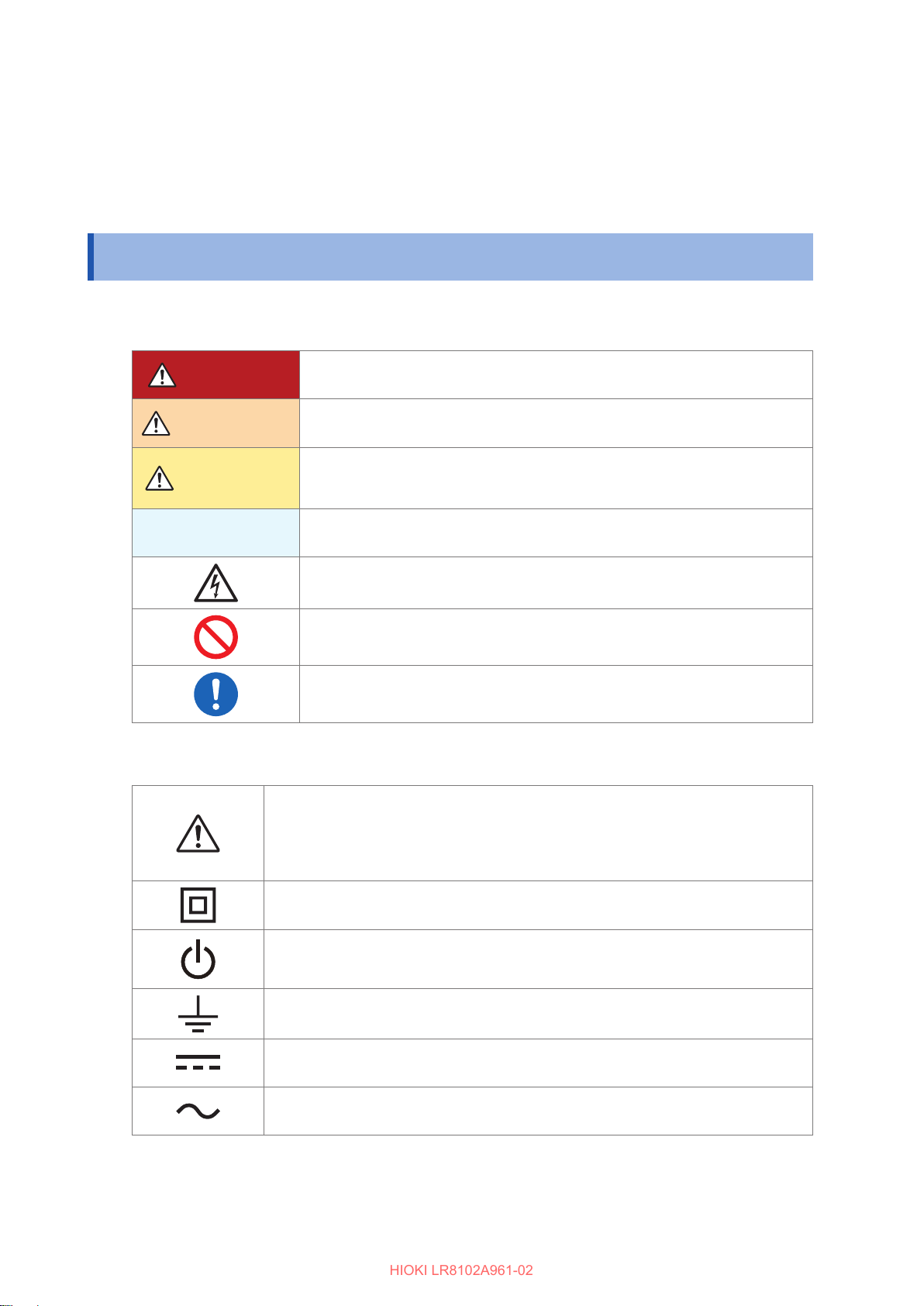
In this manual, the risk levels are classied as follows.
DANGER
WARNING
CAUTION
IMPORTANT
Symbols on the product
Indicates the presence of a potential hazard.
For more information about locations where this symbol appears on instrument
components, see “Usage Notes” (p. 13) of the Instruction Manual, warning
messages listed at the beginning of each set of operating instructions, and the
accompanying document entitled “Operating Precautions”.
Indicates an imminently hazardous situation that, if not avoided, will result in
serious injury or death.
Indicates a potentially hazardous situation that, if not avoided, could result in
serious injury or death.
Indicates a potentially hazardous situation that could result in minor or moderate
injury, or potential risks of damage to the supported product (or to other property),
if not avoided.
Indicates information related to the operation of the instrument or maintenance
tasks with which the operators must be fully familiar.
Indicates a high-voltage hazard. Failure to verify safety or improper handling of
the instrument could lead to an electric shock, burn, or death.
Indicates prohibited actions.
Indicates an action that must be performed.
8
Indicates that the entire device is protected with double or reinforced insulation.
Indicates the power push-button switch that toggles the instrument between on and o.
Indicates a grounding terminal.
Indicates DC (Direct Current).
Indicates alternating current (AC).
Page 9
Symbols for various standards
HIOKI LR8102A961-02
Others
Symbols and Abbreviations
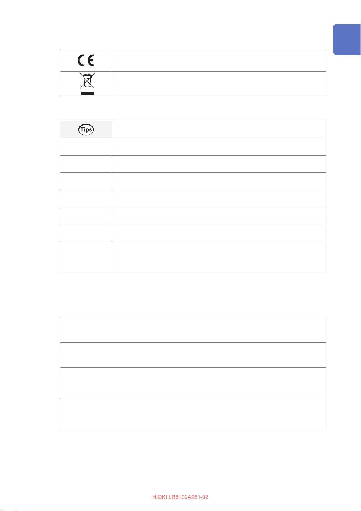
Indicates that the product complies with standards imposed by EU directives.
Indicates that the product is subject to the Waste Electrical and Electronic Equipment
(WEEE) Directive in EU member nations. Dispose of the product in accordance with
local regulations.
Indicates convenient functions and advice that are useful to know.
*
(p. ) Indicates the page number to refer to.
Bold letters Indicates the names of the elements and the keys on the screen.
[ ] Indicates the names of user interface elements on the screen.
Windows
S/s
Indicates additional information is provided below.
Indicates the default setting value. Initialization resets the setting to this value.
Unless otherwise noted, the term “Windows” is used generically to refer to Windows 7,
Windows 8, Windows 10, and Windows 11.
For this instrument, the number of times the analog input signal is digitized is indicated
in samples per second (S/s).
Example: 20 MS/s (20 megasamples per second) signies 20
second.
106 samples per
×
Accuracy labeling
The instrument accuracy is expressed by dening a limit value for errors in terms of the same unit
as the unit of reading, range, full scale, digits, and measured value.
Reading (display value)
% of reading
Indicates the value displayed by the instrument. Limit values for reading errors are
expressed as a percentage of the reading (“% of reading” or “% rdg”).
% of range
f.s.
digits
Range
Indicates the measurement range of the instrument. Limit values for range errors are
expressed as a percentage of the range (“% of range” or “% rng”).
Full scale (rated value)
This instrument mainly indicates the rated value of the current sensor.
Limit values for full-scale errors are expressed as a percentage of full scale (“% of full
scale” or “% f.s.”).
Digit (resolution)
Indicates the minimum display unit (in other words, the smallest digit that can have
a value of 1) for a digital measuring instrument. Limit values for digit errors are
expressed using digits (“dgt”).
9
Page 10
Checking Package Contents
HIOKI LR8102A961-02
Checking Package Contents
When you receive the instrument, inspect it to ensure that no damage occurred during shipment.
If you nd any damage or discover that the instrument does not perform as indicated in its
specications, please contact your authorized Hioki distributor or reseller.
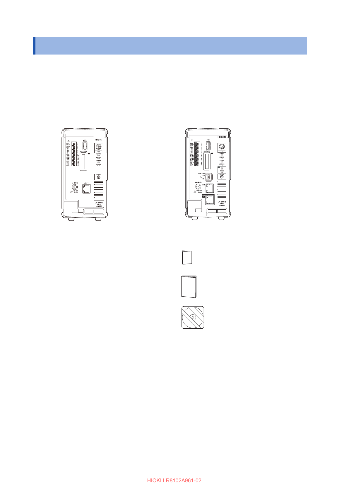
Check the package contents as follows.
Instrument
LR8101 Data Logger
Included accessories
Operating Precautions (0990A903)
Startup Guide
LR8102 Data Logger
Logger Application Disc (DVD) *
• Startup Guide
• Instruction Manual
• Logger Utility
• Logger Utility Instruction Manual
• CAN Editor
• CAN Editor Instruction Manual
• GENNECT One
*1. The latest edition can be downloaded from the Hioki website.
1
10
Page 11
Options (sold separately)
HIOKI LR8102A961-02
The options listed below are available for the instrument. See “1.3 Options” (p. 35).
To place orders, contact your authorized Hioki distributor or reseller.
Options are subject to change. Check Hioki’s website for the latest information.
M7100 Voltage/Temp Module (15 channels)
M7102 Voltage/Temp Module (30 channels)
M7103 Power Measurement Module (3 channels)
M1100 AC Power Module
Z1016 AC Adapter (2-pole grounding power cord included)
L1012 Power Cable (with unprocessed ends)
Z4001 SD Memory Card (2 GB)
Z4003 SD Memory Card (8 GB)
Z4006 USB Drive (16 GB)
9642 LAN cable
L6101 Optical Connection Cable (1 m)
L6102 Optical Connection Cable (10 m)
Safety Information
Safety Information
The instrument and measurement modules are designed in accordance with IEC 61010
International Standards, and have been thoroughly tested for safety prior to shipment. However,
failure to follow the guidelines outlined in this manual may compromise the safety of the instrument.
Before using the instrument and measurement modules, make sure to read the following safety
precautions carefully.
DANGER
Read the Instruction Manual carefully and ensure you understand its
contents before using the instrument.
Improper use of the instrument could result in serious bodily injury or damage to the
instrument.
WARNING
When using the electric measuring instrument for the rst time, perform
the measurement under supervision of experienced personnel.
Failure to do so could cause the operator to experience an electric shock.
In addition, heat generation, re, arc discharge due to short circuit, or other problems
could occur.
Wear insulating protective equipment.
This instrument measures live lines. Failure to wear the protective equipment could
cause the operator to experience an electric shock. It is stipulated in the law that
insulating protective equipment must be worn.
11
Page 12
Safety Information
HIOKI LR8102A961-02
Measurement categories
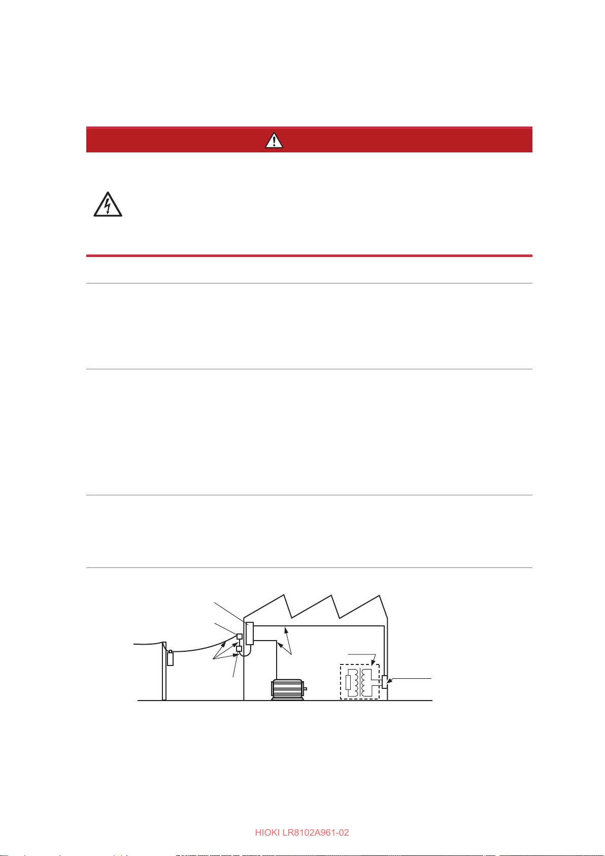
IEC 61010 denes measurement categories to facilitate safe use of measuring instruments. Test
and measurement circuits designed to be connected to a main power supply are classied into
three categories depending on the type of main power supply circuit.
DANGER
Do not use the measuring instrument to measure a main power supply
circuit that exceeds the instrument’s specied measurement category.
Do not use a measuring instrument without a specied measurement
category to measure a main power supply circuit.
Doing so may result in serious bodily injury or damage to the instrument or other
equipment.
Measurement
category II
(CAT II)
Measurement
category III
(CAT III)
Measurement
category IV
(CAT IV)
Applicable to test and measuring circuits connected directly to utilization points
(socket outlets and similar points) of a low-voltage MAINS installation.
Example: Measurements on household appliances, portable tools, and similar
equipment, and on the consumer side only of socket outlets in the
xed installation.
Applicable to test and measuring circuits connected to the distribution part of the
a building’s low-voltage MAINS installation.
Example: Measurements on distribution boards (including secondary meters),
photovoltaic panels, circuit breakers, wiring, including cables,
bus-bars, junction boxes, switches, and socket outlets in a xed
installation, as well as equipment for industrial use and some other
equipment such as stationary motors with permanent connection to
the xed installation.
Applicable to test and measuring circuits connected at the source of the a
building’s low-voltage MAINS installation.
Example: Measurements on devices installed before the main fuse or circuit
breaker in the building installation.
12
Distribution panel
Service entrance
Service drop
CAT IV
Power meter
Interior wiring
CAT III
Fixed equipment
CAT II
T
Outlet
Page 13
Usage Notes
HIOKI LR8102A961-02
Be sure to follow the precautions listed below in order to use the instrument safely and in a manner
that allows it to function eectively.
Use of the instrument should conform not only to its specications, but also to the specications of
all accessories, options, and other equipment in use.
Check before use
DANGER
Inspect the instrument and verify proper operation before use.
Use of the instrument while it is malfunctioning could result in serious bodily injury.
If you nd any malfunction or damage, contact your authorized Hioki distributor or
reseller.
See “2.1 Inspection Before Use” (p. 45) for information about inspections.
Usage Notes
Installing the instrument
Do not install the instrument in the following types of locations:
• Locations exposed to direct sunlight or high temperatures
• Areas where corrosive or explosive gases are present
• Near sources of strong electromagnetic elds or electrostatic charges
• Close to induction heating systems (such as high-frequency induction heaters
or IH cookers)
• Locations subject to mechanical vibrations
• Places where the instrument could be exposed to water, oil, chemicals, or
solvents
• High-humidity areas or places where condensation occurs
• Dusty environments
Doing so could damage the instrument or cause it to malfunction, resulting in bodily
injury.
Leave sucient space around the instrument, so that the power cord
can be unplugged.
Without sucient space around the instrument, the power supply cannot be shut
down immediately in emergency situations. Failure to do so may result in bodily
injury, re, or damage to the instrument.
WARNING
CAUTION
Do not place the instrument on an unstable stand or angled surface.
Doing so could cause the instrument to fall or overturn, resulting in bodily injury or
damage to the instrument.
Do not bend or pull the cables in environments below 0
The cables become sti in such an conditions. Bending or pulling the cables may
result in cable breakage or damaged insulation, posing a risk of electric shock to the
operator.
C.
°
13
Page 14
Usage Notes
HIOKI LR8102A961-02
IMPORTANT
• Take appropriate measures to prevent the ambient temperature near the terminal block of the
measurement module from changing. If the terminal block is exposed to air from a ventilation
fan, air conditioner, etc., a measurement error can occur during temperature measurement
using a thermocouple.
• When the environment temperature has changed signicantly, wait for at least 60 minutes
before starting the measurement after the temperature is stabilized.
CAUTION
Do not unplug the communication cable while the instrument is sending or
receiving data.
Doing so could damage the instrument.
Turn OFF the instrument and PC before connecting or disconnecting the
communication cable.
Failure to do so could damage the instrument being connected or cause it to
malfunction.
Use the same ground for the instrument and the PC.
When a communication cable is connected to the instrument with a potential
dierence between the ground circuits of the instrument and the PC, the instrument
may be damaged or malfunction.
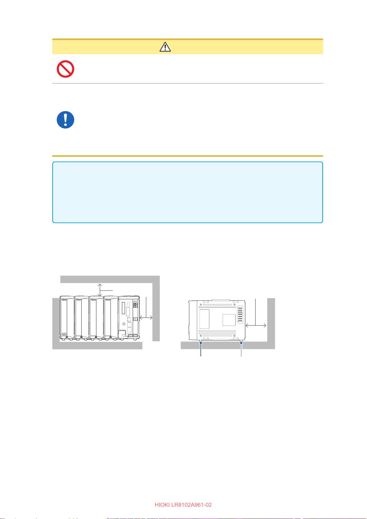
• Do not block the vents. (Leave at least 3 cm of space on the top and the right, and at least 10 cm
on the rear to keep the instrument’s temperature from rising.)
• Do not stack the instruments.
• Be sure to orient the feet so that they support the weight of the instrument as shown below.
3 cm or larger
Right side
10 cm or larger
Support foot Support foot
14
Page 15
Handling the instrument
HIOKI LR8102A961-02
Do not subject the instrument to vibration or mechanical shock while
transporting or handling it.
Do not drop the instrument on the oor or other surfaces.
Doing so could damage the instrument.
Precautions when transporting the instrument
The instrument will become heavy if numerous modules are connected. Failure to
observe occupational safety rules could lead to bodily injury or instrument damage.
Reference weights:
Usage Notes
CAUTION
• LR8102, M7103
• LR8102, M7100 × 10: approx. 14.5 kg
The instrument is classied as a Class A device under the EN 61326 standard. Use of the
instrument in a residential setting such as a neighborhood could interfere with reception of radio
and television broadcasts. In such cases, the operator should take appropriate measures to
address the issue.
4, M7100 × 6, M1100: approx. 17.4 kg
×
15
Page 16
Usage Notes
HIOKI LR8102A961-02
Precautions for measurement
Do not input voltage between the channels that exceeds the maximum
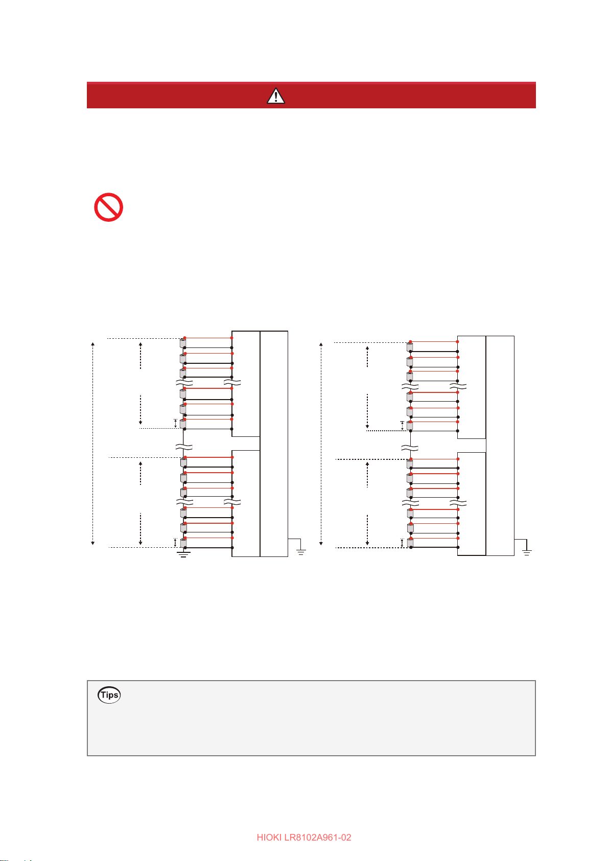
input voltage of the measurement modules, the maximum rated line-toground voltage, the maximum rated voltage between channels, or the
maximum rated voltage between modules.
• Maximum input voltage: Between the + and − inputs
• Maximum voltage between the channels: Between any channels of the same
module
• Maximum rated line-to-ground voltage: Between ground potential and the
input terminals
• Maximum rated voltage between the modules: Between channels of dierent
modules
Doing so could result in serious bodily injury or damage to the instrument. These
rated voltages vary depending on the measurement modules. See
“13 Specications” (p. 355) for these values.
Maximum voltage
between the channels
300 V
Maximum rated
line-to-ground
voltage
1500 V
(−1500 V to
+1500 V)
between the channels
Maximum input
voltage
100 V
Maximum voltage
300 V
Maximum input
voltage
100 V
Module 1 (M7100
Module
M
+
CH1
−
+
CH2
−
+
CH3
−
+
CH13
−
+
CH14
−
+
CH15
−
+
CH1
−
+
CH2
−
+
CH3
−
+
CH13
−
+
CH14
−
+
CH15
−
7100
DANGER
10
LR
)
LR81
8101
02
Maximum voltage
between the channels
300 V
Maximum
rated voltage
between the
modules
1500 V
(−1500 V to
+1500 V)
between the channels
Maximum input
voltage
100 V
Maximum voltage
300 V
Maximum input
voltage
100 V
Ungrounded
Module
Module 1 (M7100
+
−
+
−
+
−
+
−
+
−
+
−
+
−
+
−
+
−
+
−
+
−
+
−
7100
M
CH1
CH2
CH3
CH13
CH14
CH15
CH1
CH2
CH3
CH13
CH14
CH15
LR8101
10
LR8102
)
16
If you use modules with diering maximum rated voltages between modules for a
measurement target connected in series, such as a battery pack, the specications of
the module with the lower maximum rated voltage between modules will apply.
Example: Mixing the M7100, M7103, and M7102 to measure a battery pack
This combination cannot be used to measure a battery pack over 600 V,
because the maximum input voltage between the modules is limited to
600 V DC.
Supplementary explanation about maximum voltage between the channels
When the maximum voltage between the channels is 300 V, make sure that the potential
dierence between the adjacent channels, as well as among all the channels, is within 300 V.
For example, the potential dierence should be within 300 V between CH1 and CH2, and also
between CH1 and CH15.
Page 17
Usage Notes
HIOKI LR8102A961-02
DANGER
Do not touch any input terminals on the VT (PT), CT, or instrument when
they are in operation.
Doing so could result in serious bodily injury.
Do not use the instrument to measure circuits that exceed the ratings or
specications of the instrument.
Doing so could cause damage to the instrument or overheating, resulting in serious
bodily injury.
Do not use the instrument and measurement modules to measure a
main power supply circuit.
The voltages to earth of the M7100 and M7102 measurement modules are
compatible with CAT II. However, these modules cannot be used for a measurement
in CAT II, CAT III, or CAT IV.
Never input a voltage in CAT II, CAT III, or CAT IV between the measurement
terminals.
Failure to do so could cause the operator to experience an electric shock or damage
the instrument.
Do not short-circuit the two wires of the measurement line using the
metallic tips of the sensors.
Doing so can cause arc ash, resulting in serious bodily injury or damage to the
device or other equipment.
WARNING
Do not allow the instrument to become wet.
Do not operate the instrument with wet hands.
Doing so could cause the operator to experience an electric shock.
Securely connect the measurement cables to the input terminals.
Loose terminals could result in increased contact resistance, causing the product to
become hot or burn up or resulting in bodily injury or re.
When no measurement module is connected, install the connector
cover.
Failure to do so could cause the operator to experience an electric shock or damage
the instrument and measurement modules.
Eect of induced voltage
Due to induced voltage, the displayed value may become unstable when there is no input;
however, this is not a malfunction.
A physical phenomenon called short range ordering occurs in K and T thermocouples. This
phenomenon may prevent accurate measurement between 250°C and 600°C.
Select the sensor while referring to the manufacturer of the thermocouples to be used.
17
Page 18

Usage Notes
HIOKI LR8102A961-02
Shipping Precautions
• Store the packing materials after unpacking. When shipping the instrument, use the original
packing materials that were used when the instrument was delivered.
• To ship the instrument safely, use the box and cushioning material in which it was originally
shipped. However, do not use the original box or cushioning material if the box is torn or
deformed or the material is crushed. If you are unable to use the original box and cushioning
material, contact your authorized Hioki distributor or reseller.
• Before packing the instrument, be sure to disconnect the power cords.
• When transporting the instrument, exercise care to avoid dropping it or otherwise subjecting it to
rough handling.
Precautions related to disc usage
• Exercise care to keep the recording surface of the disc free of dirt and damage.
• If you need to label the disc, for example with text, use a marker with a soft tip.
• Store discs in protective cases. Avoid exposing the disc to direct sunlight, high temperatures, or
high humidity.
• We are not responsible for any issues that may arise in your computer system due to the use of
this disc.
18
Page 19
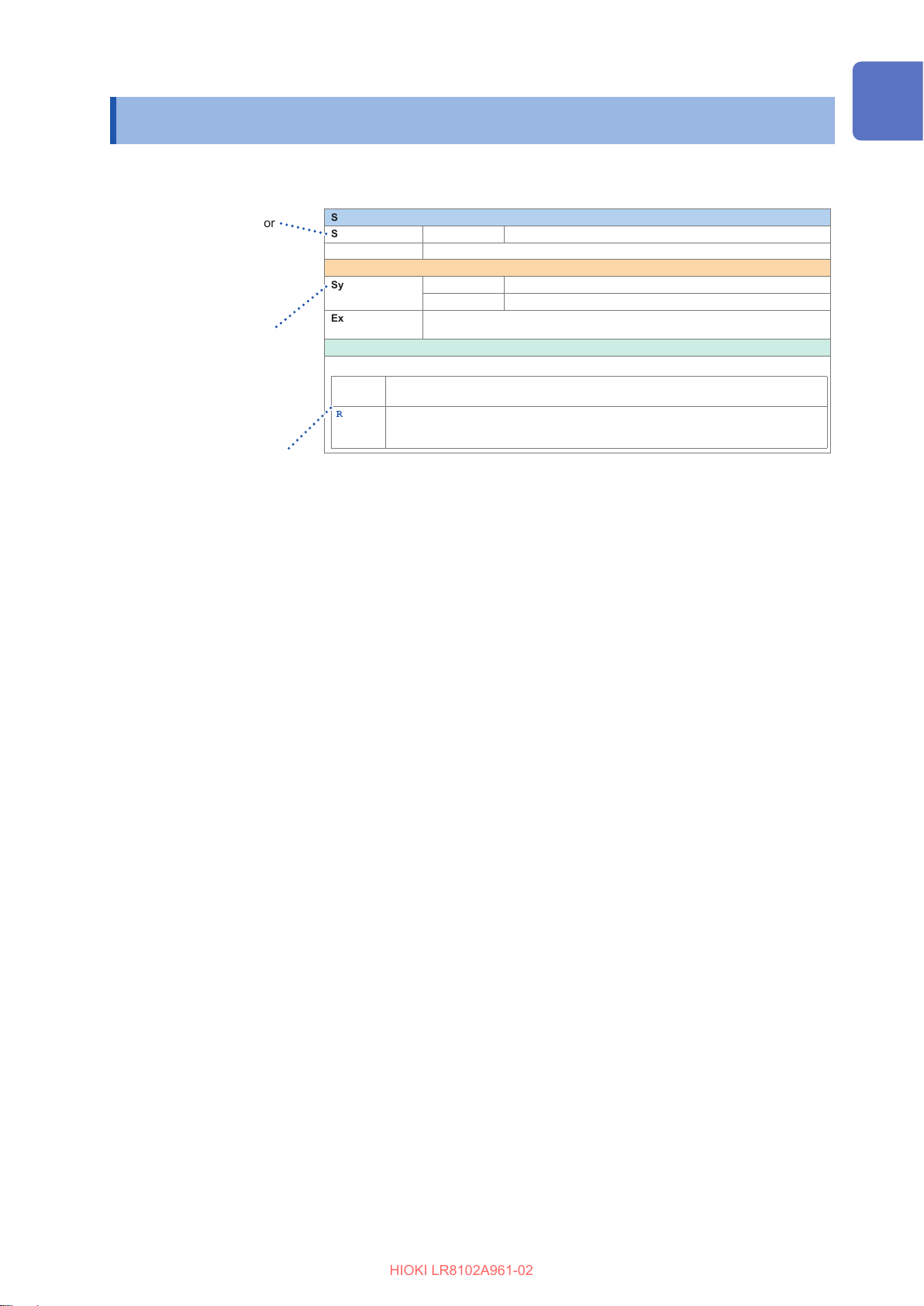
About This Manual
HIOKI LR8102A961-02
Set whether or not to repeat the recording operation.
5
The command is required for
the setting.
Sending the command as shown
in the example will update the
settings on the instrument.
The command is required
for inquiring about the setting.
Sending the command as
shown in the example allows
you to acquire the setting
and measured value in the
(Response) format.
Setting item and description
The congurable item and its
description.
Settings
Syntax Command
Example
Query
Syntax Query
Example
Parameter
A$
SINGle
REPEat
:TRIGger:MODE A$
:TRIGger:MODE REPEat
:TRIGger:MODE?
Response
:TRIGger:MODE?
(Response)
= SINGle, REPEat
Repetitive recording OFF
The measurement is completed with one recording.
Repetitive recording ON
The recording is repeated.
Executing the
STOP
A$
:TRIGGER:MODE REPEAT
command ends the measurement.
About This Manual
(When the header is ON)
19
Page 20
Communication Method
HIOKI LR8102A961-02
Communication Method
Command
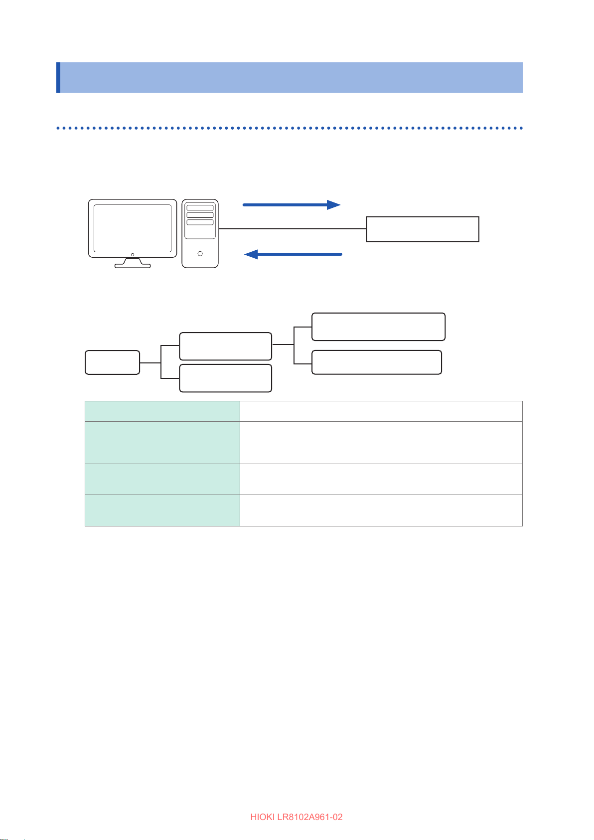
Various communication commands are available to control the instrument via the interface.
The communication commands include the program messages, which are sent from a PC to the
instrument, and the response messages, which are sent from the instrument to a PC.
PC
The data sent and received between communication devices is referred to as a message.
The messages are categorized as shown in the gure below.
Program messages
Instrument
Response messages
Command Program message
Program Message
Message
Response messages
Program messages These messages are sent from the controller to the instrument.
These messages are sent from the instrument to the controller. The
Response messages
Command program messages
Query program messages
message is created after a query program message is received and
its syntax is checked.
These messages are the commands to control the instrument, such
as setting or resetting the instrument.
These messages are the commands to query the results of
operations, measurements, and the setting status of the instrument.
Query Program message
The command program messages and the query program messages are collectively referred to as
the commands. (The commands are written in Hioki's proprietary SCPI language.)
20
Page 21
Communication Method
HIOKI LR8102A961-02
Message format
Program messages
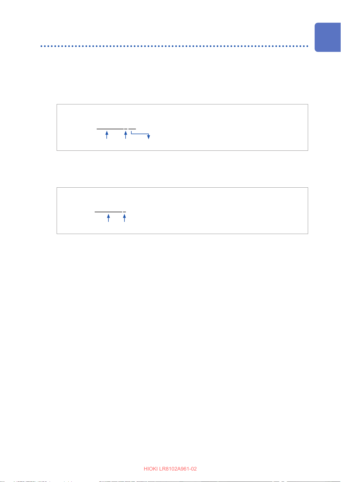
The program messages can be categorized into command program messages and query program
messages.
(1) Command program messages
Commands to control the instrument, such as setting or resetting the instrument
Example: Command to set the header
:HEADer ON
Header part Space Data part
(2) Query program messages
Commands to query the results of operations, measurements, and the setting status of the
instrument
Example: Command to query the current header settings
:HEADer?
Header part Question mark
See “Header” (p. 22), “Separator” (p. 23), and “Data part” (p. 24).
Response messages
The response message is created after a query message is received and its syntax is checked.
If any error occurs when a query message is received, no response message is created for the
query message.
21
Page 22
Communication Method
HIOKI LR8102A961-02
Command syntax
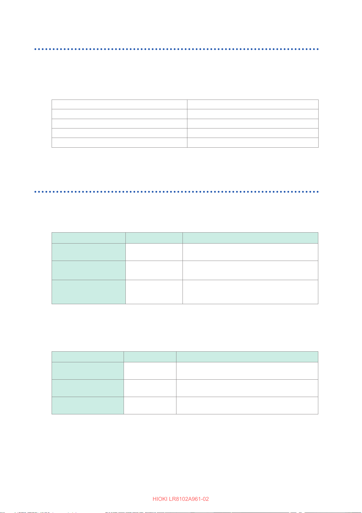
There are two command description formats as follows:
• Long form that can be associated with functions
• Abbreviated short form
In this manual, the short-form part is written in uppercase, while the remaining part is written in
lowercase. Commands with both uppercase and lowercase letters are accepted.
:SYSTem:COMMunicate:LAN:IPADdress
:SYSTEM:COMMUNICATE:LAN:IPADDRESS
:SYST:COMM:LAN:IPAD
:SYST:COMM:LAN:IPADD
:SYST:COMM:LAN:IPA
Description in this manual
OK (long form)
OK (short form)
Results in a command error.
Results in a command error.
The response messages from the instrument are returned in the long form with uppercase letters.
Header
The program messages require a header.
(1) Command program headers
There are the following three types:
Command type Example Description
Single command header
Combined command
header
:HEADer ON
:SYSTem:DATE
24,1,2
Header that consists of a single word starting with an
alphabetical character
Header that consists of multiple single command
headers separated with colons (:)
Standard command
header
*RST
Header that starts with an asterisk (*) indicating the
standard command header (as specied in IEEE
488.2)
(2) Query program header
This header is used to query the setting status of the instrument or query the measured values.
As shown in an example below, a program header ending with a question mark (?) is recognized as
a query.
Command type Example Description
Single command header
Combined command
header
Standard command
header
:HEADer?
:SYSTem:DATE?
*IDN?
Header that consists of a single word starting with an
alphabetical character
Header that consists of multiple single command
headers separated with colons (:)
Header that starts with an asterisk (*) indicating the
standard command header (as specied in IEEE 488.2)
22
Page 23
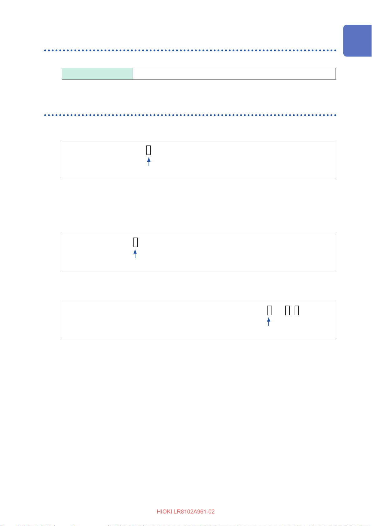
Communication Method
HIOKI LR8102A961-02
Message terminator
The instrument can accept the following as a message terminator.
LAN1 LF, CR+LF
The terminator for response messages is xed to CR+LF.
Separator
(1) Message unit separator
Multiple message can be described in a single line by connecting them using semicolons (;).
Example:
If a series of messages is described continuously and an error occurs in the sentence, the
messages after the error and before the terminator are not executed.
(2) Header separator
A message with a header and data can be separated into the header and data parts by using a
space (blank).
Example:
(3) Data separator
A message with multiple data sets requires commas (,) between the data sets.
Example:
:HEADer ON;*OPC?
Semicolon
:HEADer ON
Space
:SYSTem:COMMunicate:LAN:IPADdress 192,168,1,1
Comma
23
Page 24
Communication Method
HIOKI LR8102A961-02
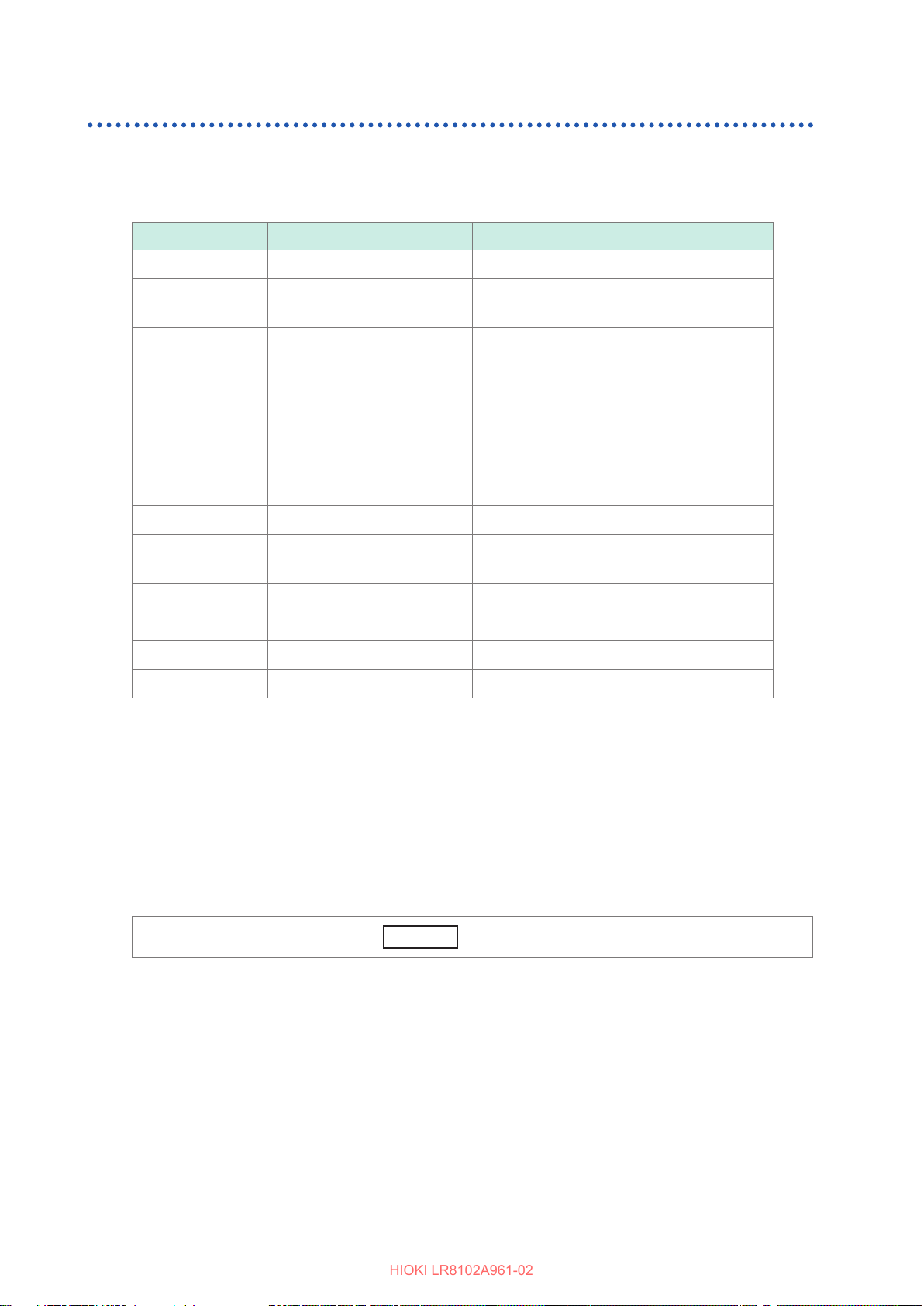
Data part
The instrument uses the character data or the decimal numerical value data for the data part
depending on the commands.
The data eld is expressed as follows.
Symbol Meaning Example
A$ Character string data OFF, ON
module$ Module data MODULE1 to MODULE10
PLS&ALM, CALC, CALC1, CALC2*
ch$ Channel data CH1_1 to CH10_30*
1
PLS1
LOG
ALM1 to ALM4
ALARM*
2
W1 to W30
M1URMS1 to M4HST3*
3
pls$ Pulse channel data PLS1
alm$ Alarm channel data ALM1 to ALM4
w$ Waveform calculation
W1 to W30
channel data
A, B, C,… Numerical value data 10, -20, 1.5E+05, 0.1
A<NR1> Integral number data +15, -20, 25
A<NR2> Fixed-point data +1.23, -4.57, 7.89
A<NR3> Floating-point data +10.0E-03, -2.3E+03, 5E+03
For the settings of numerical values, all of the <NR1 to 3> formats are accepted.
*1. Channel data of M7100 and M7102
*2. The alarm function itself is the target.
*3. Channel data of M7103 (p. 145)
*4. CALC1 groups together W1 through W15, while CALC2 groups together W16 through W30.
4
(1) Character data
The data always starts with an alphabetical character and consists of alphabetical and numerical
characters. For the character data, both uppercase and lowercase letters are accepted. However,
the response messages from the instrument are always returned with uppercase letters.
As with the command syntax, the long and short forms are available and both are accepted.
Example:
:TRIGger:MODE SINGle
(2) Decimal numerical value data
For the numerical value data, the NR1, NR2, and NR3 formats are available. Each format can
accept numerical values with and without a sign. Numerical values without a sign are treated as
positive numerical values.
In addition, if a numerical value is described to a decimal place that cannot be processed by the
instrument, the value is rounded o to the next higher decimal place.
• NR1 integral number data (example: +12, −23, 34)
• NR2 decimal fraction data (example: +1.23, −23.45, 3.456)
• NR3 oating-point exponential notation data (example: +1.0E-2, −2.3E+4)
The format including all of the three formats above is referred to as the “NRf” format.
24
Page 25
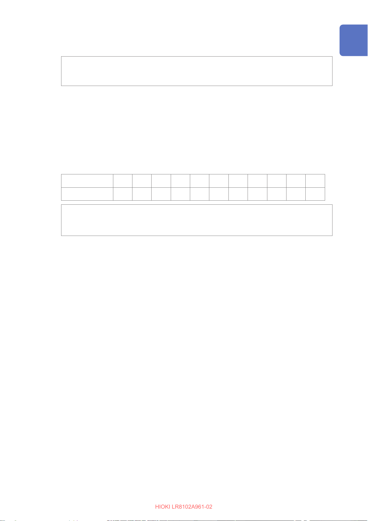
The instrument can accept numerical values in the NRf format.
HIOKI LR8102A961-02
The response data are sent in the format specied for each command.
Communication Method
Example of NR1 format:
Example of NR2 format:
Example of NR3 format:
(3) Character string data
• The character string data are placed between quotation marks.
• The data consists of 8-bit ASCII characters. However, some commands including the comment
setting are sent and received in Shift_JIS.
• A character that cannot be processed with the instrument is replaced with an underscore (_).
• As quotation marks, only double quotations (") can be sent. However, both double and single
quotations (') can be received.
• In the commands, a single quotation (') can be used instead of a double quotation (").
The special characters can be entered as follows.
PC
LR8101, LR8102
Example:
:COMMent:TITLe 'HIOKI'
:COMMent:TITLe "HIOKI"
:COMMent:TITLe "~o"
^2 ^3 ~u ~o ~e ~c ~+ ~, ~; ^^ ~~
2 3 µ
:SYSTem:THINOut 10
:CONFigure:SAMPle 0.1
:ALARm:ANALog:LEVEl ALM1,CH1_1,+1.0E-3
Ω
ε
° ±
'
"
^ ~
25
Page 26
Communication Method
HIOKI LR8102A961-02
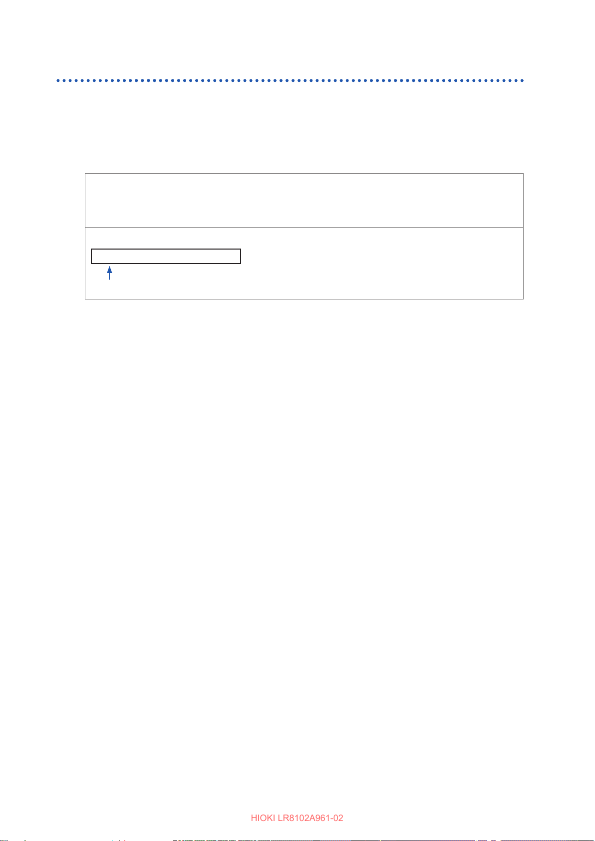
Abbreviation of combined command header
When the commands with a common leading part are combined, the repeated part can be omitted
as long as the commands are described continuously.
This common part is referred to as a “current path”. Until the current path is cleared, the subsequent
commands are analyzed assuming that the current path is omitted.
An example of using the current path is shown below.
Normal notation
:SYSTem:COMMunicate:LAN:IPADdress 192,168,1,1;:SYSTem:COMMunicate:
LAN:SMASk 255,255,255,0
Abbreviated notation
:SYSTem:COMMunicate:LAN:IPADdress 192,168,1,1;SMASk 255,255,255,0
This part denes a current path, which can be omitted in the subsequent commands.
The current path is cleared under the following situations.
• When the power is turned ON
• When a command starting with a colon (:) or an asterisk (*) is sent
• When a message terminator is detected
The single and combined command headers require no colon (:) at the beginning. However, it is
recommended to place a colon (:) at the beginning of a command in order to prevent confusion
with abbreviated forms and avoid malfunction.
26
Page 27
Output queue and input buer
HIOKI LR8102A961-02
(1) Output queue
The size of an output queue is 200 kilobytes.
The response messages are stored here and read out from the controller.
A response message exceeding 200 kilobytes results in a query error.
The output queue is cleared under the following situations.
• When the controller has read out a response message
• When the power is turned ON again
• When the instrument has received a message about the next target for processing.
(2) Input buer
The size of an input buer is 200 kilobytes.
Received messages are input in this buer and executed sequentially.
However, the
:ABORT
command is executed immediately when received.
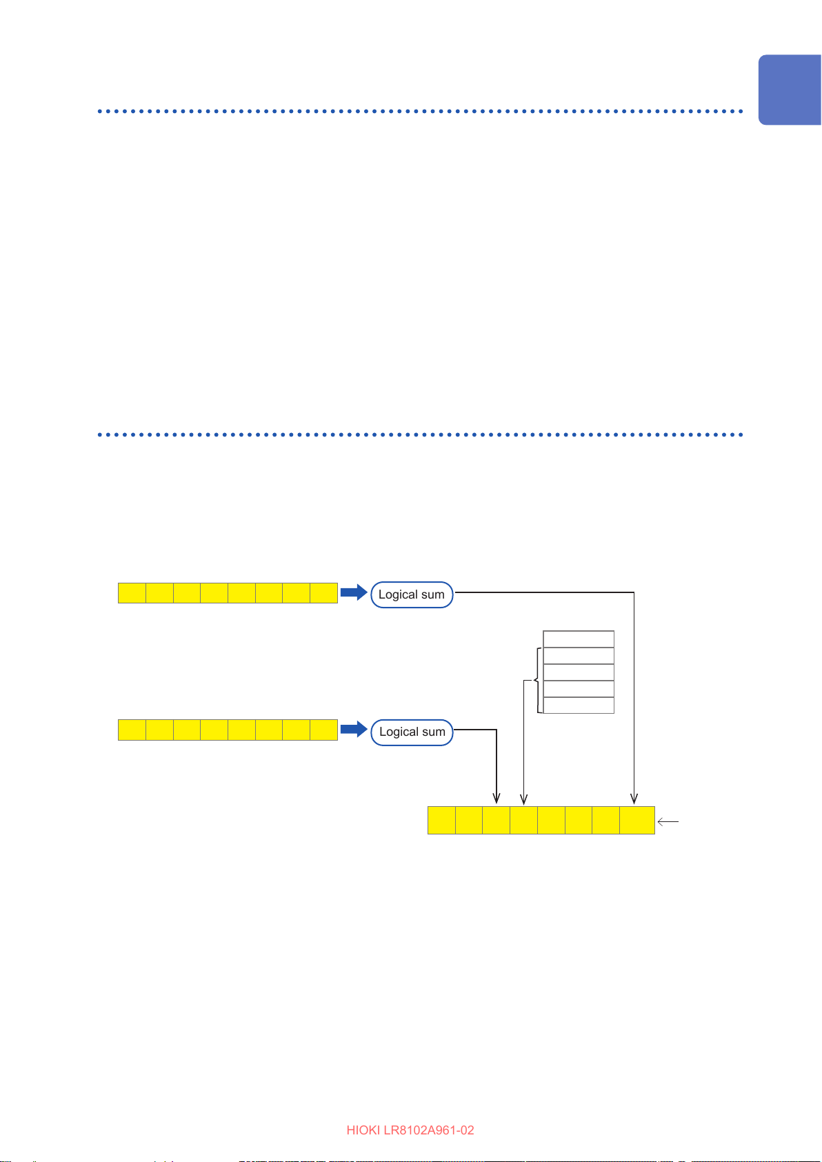
Register
Communication Method
The instrument is equipped with the following registers specied in IEEE 488.2 as shown in the
gure below.
• Standard Event Status Register
• Status Byte Register
• Event Status Register 0
Event Status Register 0 (read out with
7 6 5 4 3 2 1 0
Standard Event Status Register (read out with
7 6 5 4 3 2 1 0
:ESR0?
)
Logical sum
*ESR?
Logical sum
Data are stored in
the output queue
)
7 6
ESB MAV
NF (LF)
Data
Data
Data
Data
Output queue
Status Byte Register
3 2 1
ESBO
Read out
*STB?
with
27
Page 28
Communication Method
HIOKI LR8102A961-02
(1) Status byte
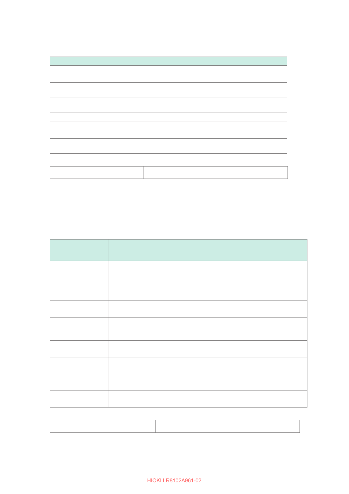
Each bit of the status byte is a summary (logical sum) of the event register corresponding to the bit.
Status Bar Description
Bit 7 Unused: 0
Bit 6 Unused: 0
Bit 5
(ESB)
Bit 4
(MAV)
Bit 3 Unused: 0
Bit 2 Unused: 0
Bit 1 Unused: 0
Bit 0
(ESB0)
To read out the status byte, use the following command.
Event summery bit
Represents a summary of the Standard Event Status Register.
Message available
Indicates that there is a message in the output queue.
Event summery bit 0
Represents a summary of Event Status Register 0
Reading out the status byte
*STB?
(2) Standard Event Status Register (SESR)
The summary of this register is set on bit 5 of the status byte.
The contents of the Standard Event Status Register is cleared under the following situations.
• When the
• When the content has been read out with the
*CLS
command is received
*ESR?
query
• When the power is turned ON again
Standard Event
Status Register
(SESR)
Bit 7
(PON)
Bit 6
(URQ)
Bit 5
(CME)
Bit 4
(EXE)
The power is turned ON again.
The power has been shut down after this register was read out for the last time. 1
when the power is turned ON.
User request
Unused (0)
Command error
The received command contains an error. Syntax error, semantic error.
Execution error
The command being executed by the instrument contains an error.
Range error, mode error.
Description
28
Bit 3
(DDE)
Bit 2
(QYE)
Bit 1
(RQC)
Bit 0
(OPC)
To read out the Standard Event Status Register, use the following command.
Standard Event Status Register
Device dependent error
Query error
Empty queue, lost data (queue overow)
Request of controller privilege (unused)
Unused (0)
Operation completed
Set only for the
*OPC
command.
*ESR?
Page 29
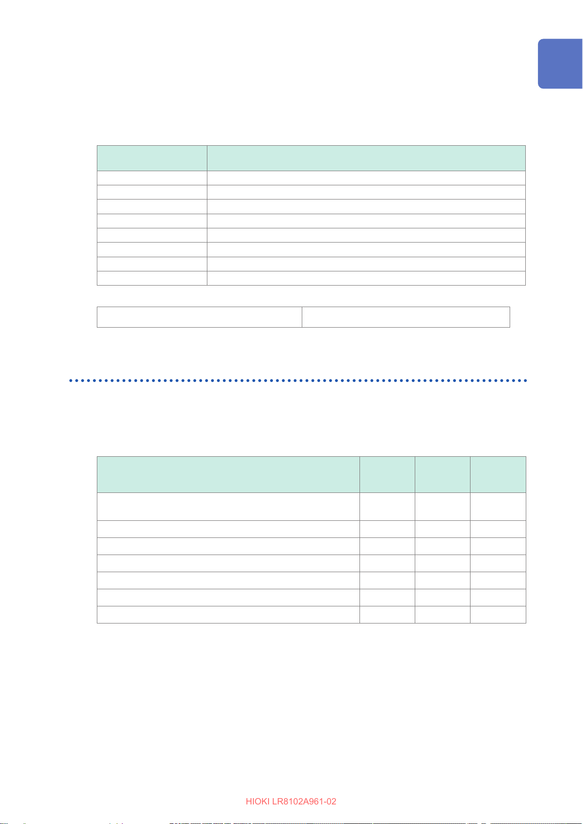
(3) Event Status Register 0 (ESR0)
HIOKI LR8102A961-02
The summary of this register is set on bit 0 of the status byte.
The contents of the Event Status Register is cleared under the following situations.
• When the
• When the content has been read out with the
*CLS
command is received
:ESR0?
query
• When the power is turned ON again
Communication Method
Event Status Register 0
(SESR0)
Bit 7 Unused: 0
Bit 6 Unused: 0
Bit 5 Unused: 0
Bit 4 Unused: 0
Bit 3 Unused: 0
Bit 2 Trigger standby end (set when the trigger is activated)
Bit 1 START process end (set when STOP is executed)
Bit 0 Error or warning occurred
To read out the status byte, use the following command.
Reading out Event Status Register
:ESR0?
Description
Items to be initialized to the default status
The following items are initialized to the default status when the instrument is initialized.
For the initialization of the device-specic functions, see “14.8 Settings After Initialization (System
Reset)” (p. 419).
Register
Device-specic functions (measurement conditions,
compensation value, etc.)
Output queue
Input buer
Status byte register
Event register
Enable register
Current path
*1. Other than the MAV bit are cleared.
*2. The PON bit (bit 7) is excluded.
When the
power is
turned ON
–
2
*
: Initialized, –: Not initialized
*RST
Command
– –
– –
–
–
– –
– –
*CLS
Command
–
*
1
29
Page 30

Communication Method
HIOKI LR8102A961-02
30
Page 31
1
HIOKI LR8102A961-02
Overview
1.1 Product Overview and Features
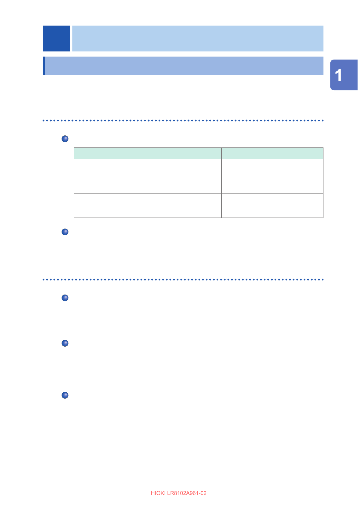
The instrument is a multichannel data logger that combines individual measuring modules. It is
used for recording physical readings, including temperatures and voltages.
Both LR8101 and LR8102
Choice of measurement modules according to applications
Features Modules
Maximum rated line-to-ground voltage is 1500 V and
voltage recording at intervals of 5 ms.
Temperature recording in 30 channels M7102 Voltage/Temp Module
High precision power recording
Up to ten measurement modules can be connected
Up to 10 measurement modules can be connected to a single instrument.
However, a single instrument can accommodate a maximum of four M7103 modules.
Each instrument can accommodate a single power supply module.
M7100 Voltage/Temp Module
M7103 Power Measurement Module
(Requires instrument rmware V1.50 or
later)
Overview
LR8102 only
Data output based on UDP
Measurement data are output for every sampling in real time. The fastest speed is achieved with
intervals of 5 ms.
This is useful when realtime processing is required, such as HILS.
Multiple instruments synchronized for measurement
Synchronized measurement is enabled with an optional L6101 Optical Connection Cable (1 m) or
L6102 Optical Connection Cable (10 m).
The measurement data from all of the synchronized instruments can be output from LAN2 of the
primary instrument.
Data output via CAN
The measured value can be output via a Controller Area Network (CAN).
The value can be used for data integration with the information of an in-vehicle device, such as the
battery management system (BMS).
31
Page 32
Part Names and Functions
HIOKI LR8102A961-02
1.2 Part Names and Functions
LR8101 and LR8102 Data Loggers
Front Rear
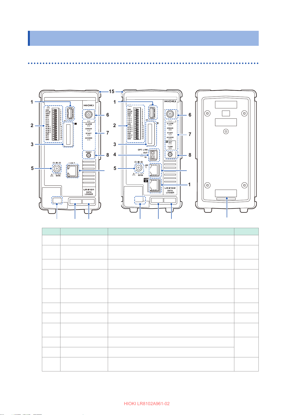
LR8101
LR8102
LR8101, LR8102
No. Name Function Reference
USB connector Optional USB drive can be connected. p. 75
External control
terminal
SD card slot Optional SD memory card can be inserted. p. 74
Optical
synchronization
connector*
Power supply
terminal
POWER key Allows you to turn ON and OFF the power. p. 71
LED See the next page p. 33
RESET key
LAN1 port LAN cable can be connected. (100BASE-TX/1000BASE-T)
LAN2 port*
MAC address
(LAN1)
1
1
Allows you to control the instrument with external signals.
Alarm signal can be output.
Optional optical connection cable can be connected. p. 65
Optional Z1016 AC Adapter can be connected.
External power supply can be connected (10 V to 30 V DC).
Allows you to initialize the settings.
Allows you to cancel the warning status.
LAN cable can be connected. (100BASE-TX/1000BASE-T)
Indicates the MAC address assigned to LAN1. Do not remove
it as the number is required for management.
p. 61
p. 48
p. 34
p. 85
−
32
*1. LR8102 only
Page 33
Part Names and Functions
HIOKI LR8102A961-02
No. Name Function Reference
For the latest information, check Hioki’s website.
Serial number
Do not remove it as the number is required for management.
Share this number when contacting your reseller.
−
*1. LR8102 only
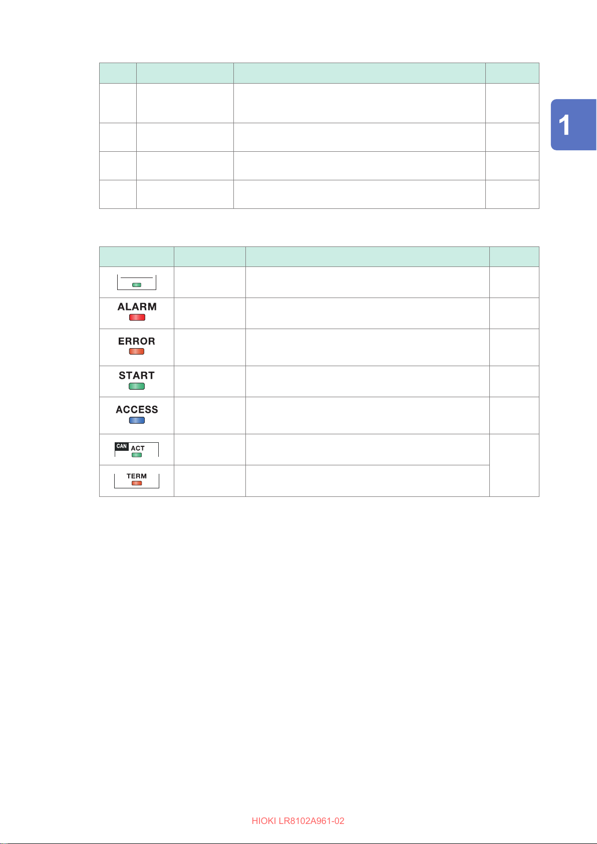
LED
Cable hook
MAC address
(LAN2)*
Connecting cover
LED Name Function Reference
1
POWER Lights up when the power is ON. p. 71
ALARM Lights up when an alarm is issued. p. 247
ERROR
START Lights up while measurement is performed. p. 171
ACCESS
To prevent the AC adapter from coming o, pass the AC
adapter cable through this hook.
Indicates the MAC address assigned to LAN2. Do not
remove it as the number is required for management.
When using the instrument without connecting a module,
install the cover.
Blinks when an error occurs. Lights up when a warning
occurs.
Lights up when the SD memory card or USB drive is
accessed.
p. 46
−
p. 46
p. 458
p. 72
Overview
1
ACT *
TERM *
Blinks when the CAN output is activated.
1
Lights up when the CAN terminator is ON.
p. 63
*1. LR8102 only
• The LEDs light up in sequence until the startup is completed.
ALARM → ERROR → START → ACCESS
• When the instrument is updated, the LEDs blink in sequence according to the progress.
ALARM → ERROR → START → ACCESS
• When the ROM and RAM of the instrument are checked, the LEDs blink in sequence according
to the progress.
ALARM → ERROR → START → ACCESS
33
Page 34
Part Names and Functions
HIOKI LR8102A961-02
Key operation on the instrument
Key Function Operation Reference
Side
POWER
key
RESET key Initialization (full
Shutdown
reset)
Warning status
clear
Alarm hold clear
LR8101, LR8102
Right side
When the key is pressed once, the LED starts blinking
(approx. 5 seconds). Pressing the key again while the LED
is blinking turns OFF the power.
Holding down the key during startup fully resets the
instrument. Keep holding down the key until the LED blinks
and a buzzer sounds.
Pressing the key once in the warning status (ERROR LED
is lit) cancels the warning status.
Pressing the key once during alarm hold cancels the hold
status.
−
p. 296
p. 461
p. 247
Left side
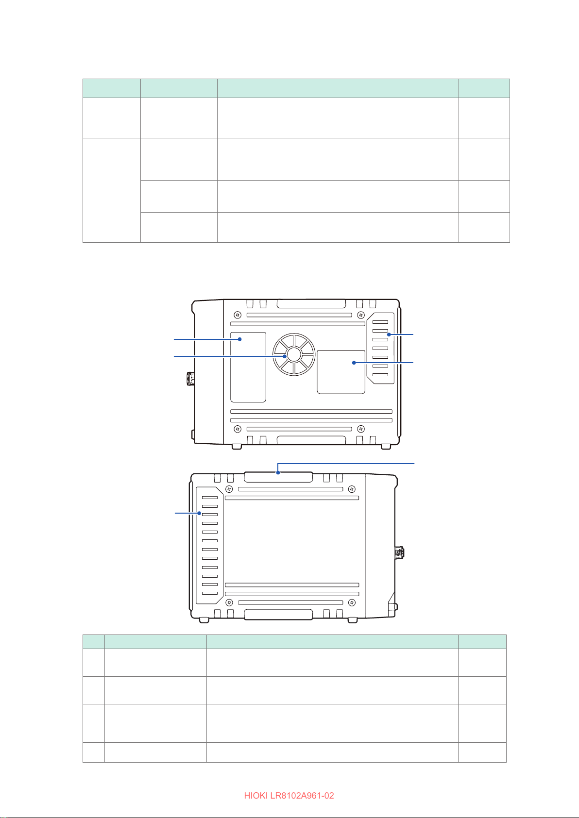
No. Name Function Reference
Description of the LED
Air vent
Connector cover
Warning Provides the important information of the instrument. −
Indicates the operation of the LED located at the front of the
instrument.
Ventilates the instrument to prevent the temperature of the
inside from going up excessively.
Under the cover, there is a connector to connect a module.
When using the instrument without connecting a module, install
the connector cover.
p. 33
p. 13
p. 46
34
Page 35
1.3 Options
HIOKI LR8102A961-02
Options
Product name Measurement target
M7100 Voltage/Temp Module Voltage, temperature (thermocouple) 15 5 ms*
M7102 Voltage/Temp Module Voltage, temperature (thermocouple) 30 10 ms*
M7103 Power Measurement Module Power (voltage, current) 3 5 ms*
*1. Only when the number of channels used in a module is eight or less and the voltage range is used.
*2. The number of channels used in a module is 15 or less.
*3. The harmonic calculation is excluded.
Number of
channels
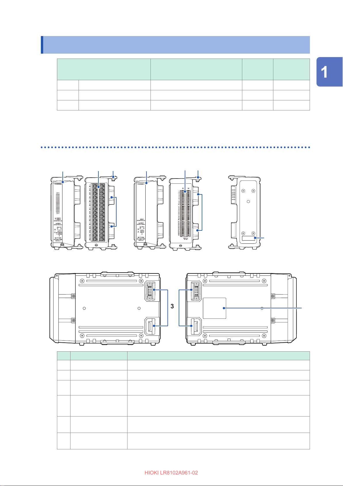
M7100, M7102 Voltage/Temp Module
Front
Rear
Shortest
sampling
interval
1
2
3
Overview
M7100
Right side
No. Name Function
Input terminal
Terminal block cover
Connector The connector for measurement module extension. Install the connector cover
Serial number For the latest information, check Hioki’s website.
Connecting plate The plate for connecting the measurement modules. After connecting the
The input terminal for each channel. The number represents the channel number.
The cover protects the terminal block. Close the cover during the measurement.
on the connector when it is not used.
Do not remove it as the number is required for management.
Share this number when contacting your reseller.
modules, x the plate using screws.
M7102
Left side
Warning label Provides the important information of the instrument.
35
Page 36
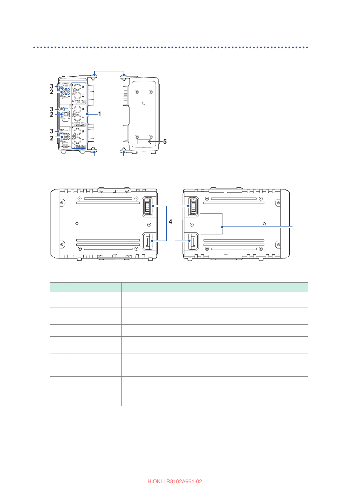
Options
HIOKI LR8102A961-02
M7103 Power Measurement Module
RearFront
Left sideRight side
No. Name Function
Voltage input
terminal
Current sensor
terminal
Status LED Indicates the operation status of the instrument. (p. 37)
Connector
Serial number
Connecting plate
Warning label
The optional voltage cords from Hioki can be connected.
A voltage output type sensor, such as the current probe and CT, can be
connected.
The connector for measurement module extension. Install the connector
cover on the connector when it is not used.
For the latest information, check Hioki’s website. Do not remove it as the
number is required for management. Share this number when contacting your
reseller.
The plate for connecting the measurement modules. After connecting the
modules, x the plate using screws.
Provides the important information of the instrument.
36
Page 37
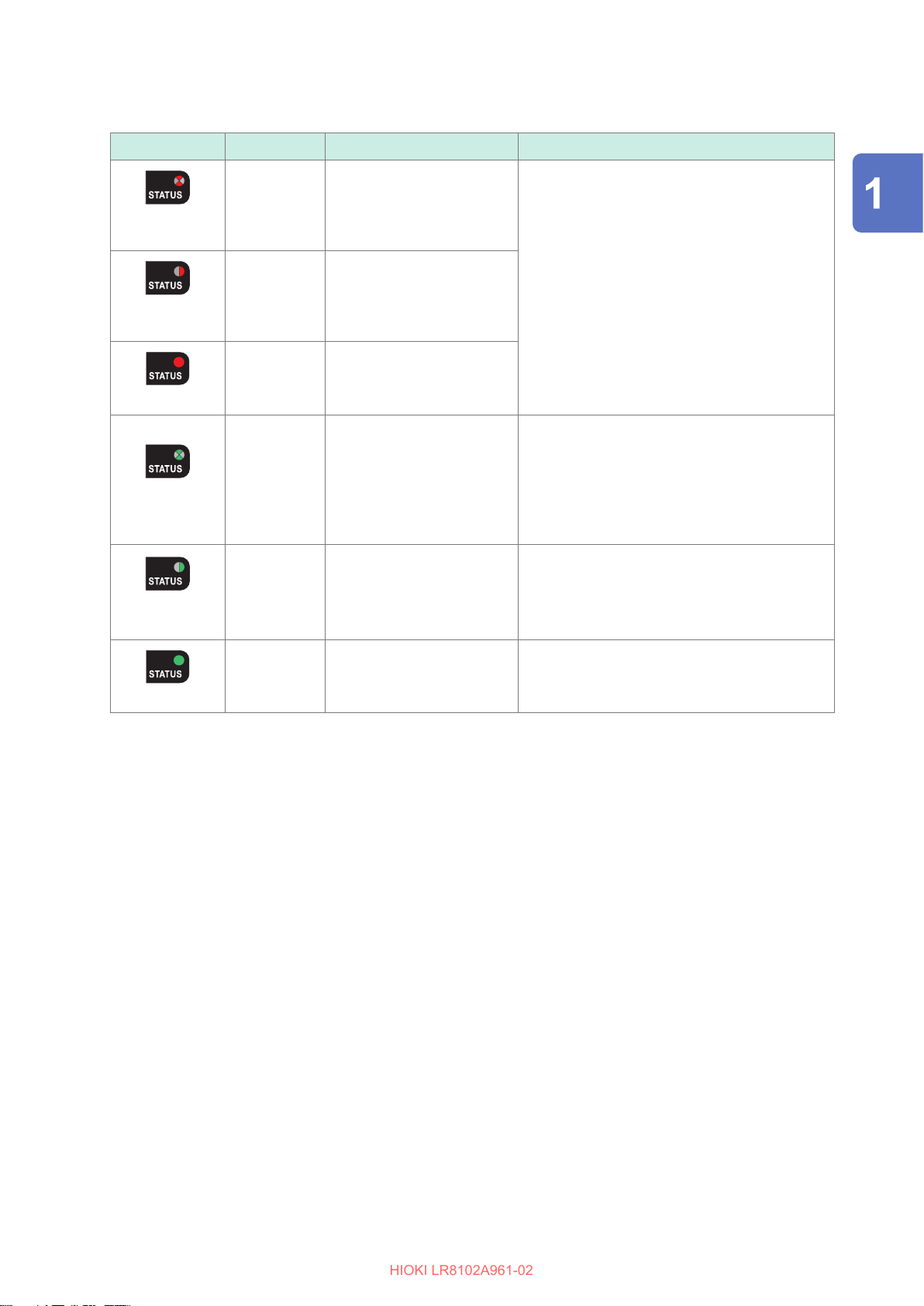
Status LED
HIOKI LR8102A961-02
LED status Target Notication summary Action
Options
Red, ashing
Red, ashing
rapidly*
slowly*
1
2
Red lamp lit
Green, ashing
Green, ashing
rapidly*
slowly*
1
1
All channels FAN error
Relevant
channel
Relevant
channel
Current sensor error
• Current/voltage over-peak
• Current/voltage overload
• Power overload
Harmonic measurement
items cannot be measured
Relevant
channel
accurately.
• Harmonic synchronization
unlock
• Outside of harmonic
frequency range
Relevant
Synchronization unlock
channel
Overview
Check the error message and warning message.
Reference: p. 460, p. 461
Check if the input signal frequency falls within
the spec range.
• Check the synchronous source setting.
• Check the voltage range and current range
settings
• Check the zero-cross lter setting
• Check the LPF setting
Relevant
channel
Normal −
Green lamp lit
*1. Repeatedly ashes 5 times per second.
*2. Repeatedly ashes 2 times per second.
37
Page 38
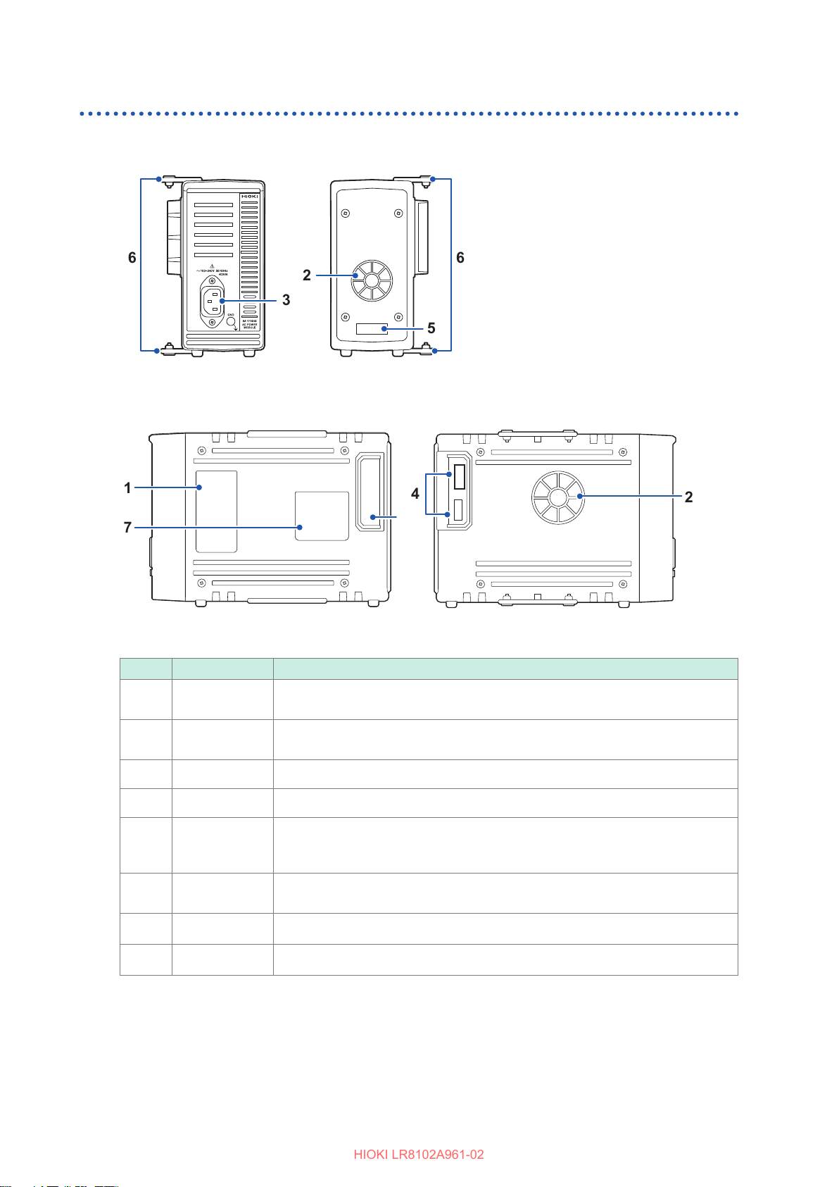
Options
HIOKI LR8102A961-02
M1100 AC Power Module
Front Rear
Right side
Left side
No. Name Function
Description of
the LED
Air vent
Power inlet The provided power cord can be connected.
Connector
Indicates the operation of the LED located at the front of the LR8101 or LR8102.
Ventilates the instrument to prevent the temperature of the inside from going up
excessively.
The connector for the instrument.
38
Serial number
Connecting
plate
Warning label
Opening
For the latest information, check Hioki’s website.
Do not remove it as the number is required for management.
Share this number when contacting your reseller.
The plate for connecting the measurement modules. After connecting the
modules, x the plate using screws.
Provides the important information of the instrument.
Ax the LR8101 or LR8102 connector cover.
Page 39
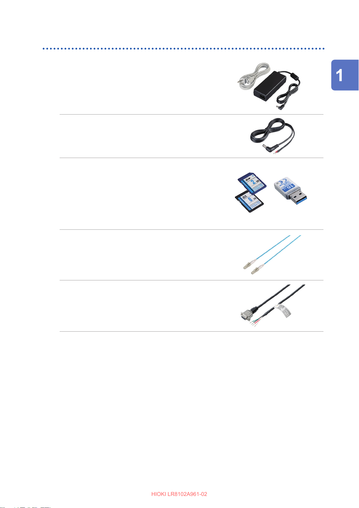
Other options
HIOKI LR8102A961-02
Z1016 AC Adapter
Allows you to drive the instrument using a commercial power
supply (AC driven).
• Rated supply voltage (100 V to 240 V AC)
• Rated power-supply frequency (50 Hz/60 Hz)
L1012 Power Cable
Allows you to drive the instrument using DC power supply.
Z4001 SD Memory Card (2 GB)
Z4003 SD Memory Card (8 GB)
Z4006 USB Drive (16 GB)
The measurement data and the setting conditions can be
stored in SD memory cards and USB drives. The operation
cannot be guaranteed if an SD memory card or USB drive
other than the optional one is used.
Options
Overview
L6101 Optical Connection Cable (1 m)
L6102 Optical Connection Cable (10 m)
The optical connection cable is required for synchronizing
multiple units of LR8102.
9713-01 CAN Cable
Option for LR8102.
The CAN Cable is used for CAN output.
Length: 2.0 m
39
Page 40
Options
HIOKI LR8102A961-02
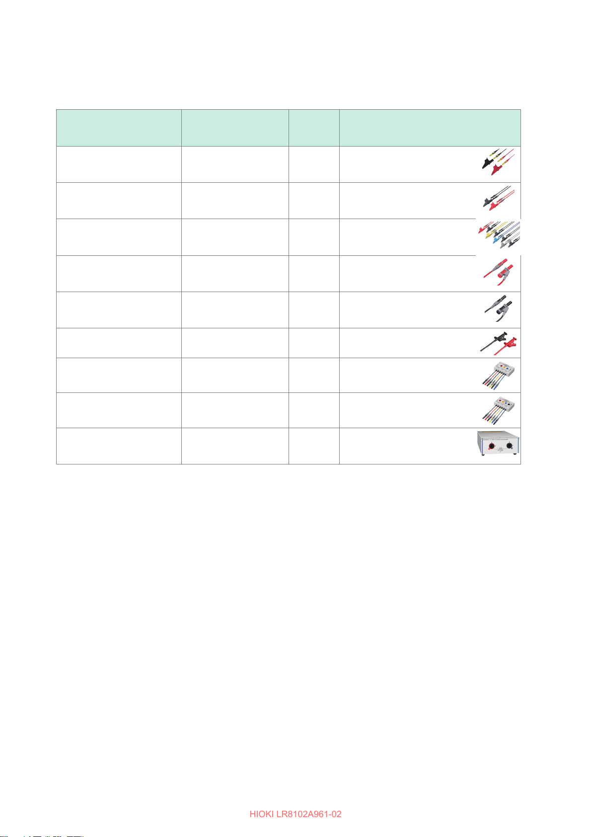
Voltage measurement options
A ø4 mm safety banana plug can be connected to the voltage input terminal of this instrument. Prepare the
appropriate voltage cords according to their intended usage.
Product name
L1025 Voltage Cord CAT II DC 1500 V,
L9438-50 Voltage Cord CAT III 1000 V, 10 A
L1000 Voltage Cord CAT III 1000 V, 10 A
L1021-01 Patch Cord CAT III 1000 V, 10 A
L1021-02 Patch Cord CAT III 1000 V, 10 A
L9243 Grabber Clip CAT II 1000 V, 1 A – Red and black ×1 each
PW9000 Wiring Adapter CAT III 1000 V, 1 A
PW9001 Wiring Adapter CAT III 1000 V, 1 A
Maximum rated voltage
Maximum rated current
AC 1000 V, 1 A
CAT III 1000 V, 1 A
CAT IV 600 V, 10 A
CAT IV 600 V, 10 A
CAT IV 600 V, 10 A
CAT IV 600 V, 10 A
CAT IV 600 V, 1 A
CAT IV 600 V, 1 A
Cable
length
(Approx.)
3 m Banana - banana (red and black
1 each)
×
Alligator clip included
3 m Banana - banana (red and black
1 each)
×
Alligator clip included
3 m Banana - banana (red, yellow,
blue, gray
Alligator clip included
0.5 m For voltage input branch
Branch-banana - banana (red
1)
×
0.5 m For voltage input branch
Branch-banana - banana (black
1)
×
– For 3P3W
– For 3P4W
Remarks
1 each, black ×4)
×
VT1005 AC/DC High
Voltage Divider
5000 V, ±7100 V peak
CAT III 1500 V
CAT II 2000 V
– For voltage measurement of
1000 V or above.
40
Page 41
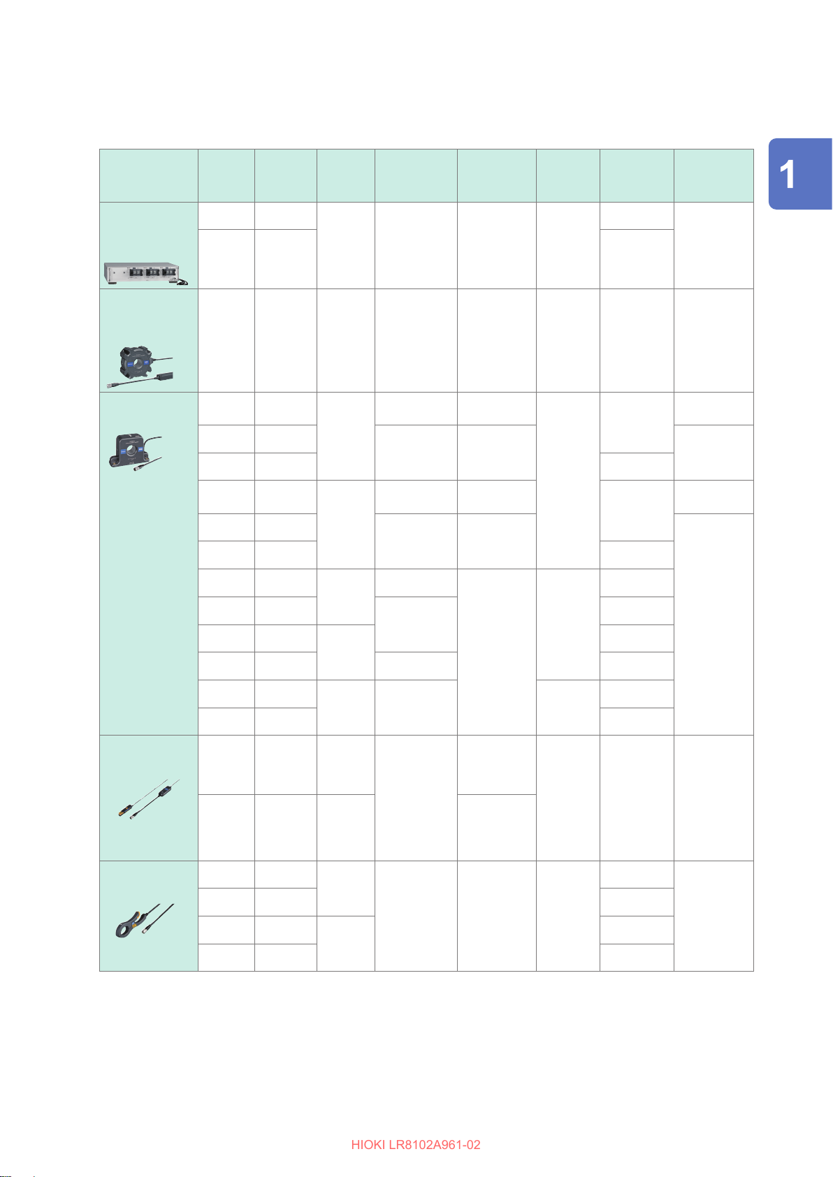
Current measurement options (ME15W connector)
HIOKI LR8102A961-02
For more details, see the instruction manual supplied with the current sensor.
Current sensor
Type
Ultra-high
accuracy direct
connection
Ultra-high
accuracy passthrough
High accuracy
pass-through
Automatic
detection
function
–
–
Product
model
PW9100A-3
PW9100A-4 4 channel
CT6904A 500 A DC to 4 MHz
CT6862-05
CT6872
CT6872-01 10 m
CT6863-05
CT6873
CT6873-01 10 m
Rated
current
rms
50 A DC to 3.5 MHz
50 A
200 A
Frequency
characteristics
DC to 1 MHz
DC to 10 MHz
DC to 500 kHz
DC to 10 MHz
Basic accuracy
(Amplitude)
0.02% rdg
±
0.005% f.s.
±
0.02% rdg
±
0.007% f.s.
±
0.05% rdg
±
0.01% f.s.
±
0.03% rdg
±
0.007% f.s.
±
0.05% rdg
±
0.01% f.s.
±
0.03% rdg
±
0.007% f.s.
±
: Yes -: No
Measurable
conductor
diameter
Measurement
terminal
M6 screw
32 mm 3 m -10°C to 50°C
ø
24 mm
ø
Number of
channels
Cable length
(Approx.)
3 channel
3 m
3 m
Operating
temperature
0
C to 40°C
°
-30
°
-40
°
-30
°
Options
range
Overview
C to 85°C
C to 85°C
C to 85°C
High accuracy
clamp
High accuracy
clamp
CT6875A
CT6875A-1
CT6876A
CT6876A-1 DC to 1.2 MHz 10 m
CT6877A
CT6877A-1 10 m
CT6830 2 A
CT6831 20 A
CT6833
CT6833-01 10 m
CT6834
CT6834-01 10 m
500 A
1000 A
2000 A DC to 1 MHz
200 A
500 A
DC to 2 MHz
DC to 1.5 MHz
DC to 100 kHz
DC to 50 kHz
0.04% rdg
±
0.008% f.s.
±
0.3% rdg
±
0.05% f.s.
±
0.3% rdg
±
0.01% f.s.
±
0.07% rdg
±
0.007% f.s.
±
36 mm
ø
80 mm
ø
5 mm
ø
20 mm
ø
3 m
10 m
3 m
3 m
Approx. 4 m
(Between
sensor and
relay box)
Approx. 0.2 m
(Between relay
box and output
connector)
5 m
5 m
-40
C to 85°C
°
Sensor:
-40
C to 85°C
°
Relay box:
-25
C to 50°C
°
Sensor and
cable:
-40
C to 85°C
°
Relay box:
-25
C to 50°C
°
41
Page 42
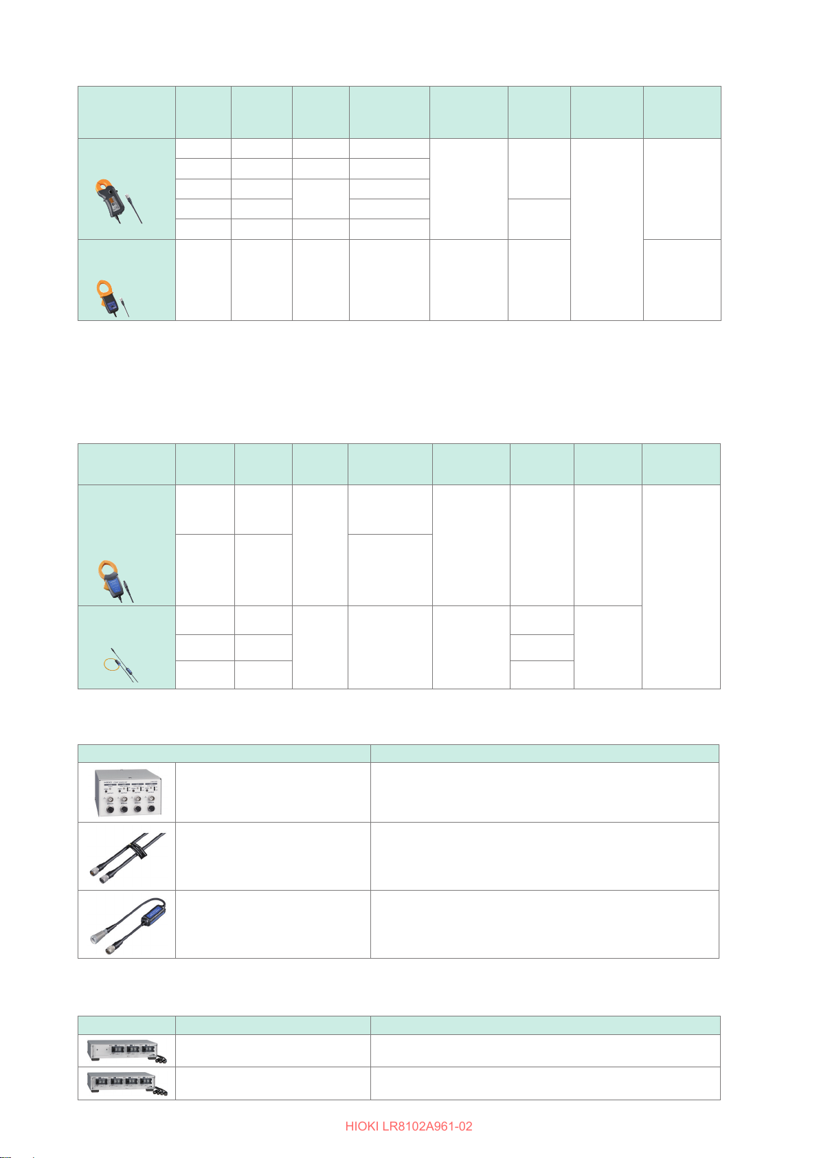
Options
HIOKI LR8102A961-02
Current sensor
Type
High accuracy
clamp
General-purpose
*1
clamp
Automatic
detection
function
–
Product
model
CT6841A 20 A DC to 2 MHz
CT6843A 200 A DC to 700 kHz
CT6844A
CT6845A DC to 200 kHz
CT6846A 1000 A DC to 100 kHz
9272-05
Rated
current
rms
500 A
20 A
200 A
Frequency
characteristics
DC to 500 kHz
1 Hz to 100 kHz
Basic accuracy
(Amplitude)
0.2% rdg
±
0.01% f.s.
±
0.3% rdg
±
0.01% f.s.
±
*1. For measurement of commercial frequency band
Current measurement options (PL14 connector)
For more details, see the instruction manual supplied with the current sensor.
To connect M7103, the CT9920 Conversion Cable is required.
Current sensor
Type
Current sensor
suitable for large
currents
Automatic
detection
function
–
–
Model
CT7742
CT7642 DC to 10 kHz
Rated
current
rms
2000 A
Frequency
characteristics
DC to 5 kHz
Basic
accuracy
(Amplitude)
1.5% rdg
±
0.5% f.s.
±
Measurable
conductor
diameter
20 mm
ø
50 mm
ø
46 mm 0°C to 50°C
ø
Measurable
conductor
diameter
55 mm 2.5 m
ø
Number of
channels
Cable length
(Approx.)
3 m
Cable length
(Approx.)
Operating
temperature
-40
°
: Yes -: No
Operating
temperature
-25
°
range
C to 85°C
range
C to 65°C
Flexible current
sensor
CT7044
–
CT7045
–
CT7046
–
6000 A 10 Hz to 50 kHz
Current measurement options (others)
Product name Remarks
CT9557 Sensor Unit 4-channel specication, addition function, power supply with RMS output
CT9904 Connection Cable
CT9920 Conversion Cable For conversion from current sensor connector PL14 to ME15W (12 pins)
The following are the made-to-order products.
100 mm
ø
1.5% rdg
±
0.25% f.s
±
ME15W (12 pins) - ME15W (12 pins) 1 m
For CT9557 connection
180 mm
ø
254 mm
ø
2.3 m
42
Product name Remarks
PW9100A-3 AC/DC Current Box 3-channel 5 A rated specication
PW9100A-4 AC/DC Current Box 4-channel 5 A rated specication
Page 43
Measurement Workow
HIOKI LR8102A961-02
1.4 Measurement Workow
The measurement procedure with the instrument is as follows.
For steps 4 to 6, the method for sending commands from a PC is explained in this manual.
For details about the command operations as well as other operations not related to the commands,
see “12 Communication with PC (Computer)” (p. 311).
1. Preparation of the instrument
See “2 Connection (Preparation for Measurements)” (p. 45).
• Install the measurement modules on the instrument.
• Connect the AC adapter.
2. Preparation of the instrument
See “2.6 Connecting Cables” (p. 54).
• Connect the LAN cable on the instrument.
• Connect the cables for the thermocouples, etc. to the terminal block of the
measurement modules.
Overview
3. Turn ON the power
See “2.7 Turning ON and OFF the Power” (p. 71).
• Pressing the POWER key turns ON the instrument.
4. Set and connect the LAN
See “2.10 Setting and Connecting the LAN” (p. 85)
5. Set the instrument
See “3.3 Setting Measurement Conditions” (p. 106).
• Before starting the measurement, set the measurement conditions using
communication commands.
See “3.1 Controlling the Instrument Using Communication Commands” (p. 101).
• Set the recording interval (sampling interval) and the recording time.
See “3.4 Setting the Voltage/Temp Module” (p. 120).
• Set the input types and ranges for the voltage, thermocouple, etc.
6. Start and stop the measurement
See “3.10 Starting and Stopping Measurement” (p. 171).
• Send the
• Send the
STARt
STOP
command to start the measurement.
command to stop the measurement.
7. Acquire the waveform data
43
Page 44
Measurement Workow
HIOKI LR8102A961-02
See “4 Acquiring Measurement Data” (p. 175).
See “4.2 Acquiring Realtime Data” (p. 180).
Select an appropriate data acquisition method according to the
application.
See “4.7 Comparison of Realtime Data Acquisition” (p. 189).
44
Page 45
Connection (Preparation for
HIOKI LR8102A961-02
2
Measurements)
This chapter explains preparation prior to starting a measurement.
For the power supply, use the AC adapter, an external power supply or M1100 AC Power Module.
Install and wire the modules and cables according to the measurement target.
An SD memory card or USB drive can be selected as a storage medium.
2.1 Inspection Before Use
DANGER
Before using the instrument, check the measurement cables to conrm
that the insulation is not worn and no metal parts are exposed.
Inspect the instrument and verify proper operation before use.
Using a damaged cable or instrument could result in serious bodily injury. Replace
with those specied by our company if you nd any damage.
Inspect the instrument before turning ON the power, and ensure that no damage occurred during
storage or shipping.
If you nd any damage, contact your authorized Hioki distributor or reseller.
Inspecting the peripheral devices
Inspect the measurement cables to conrm that the insulation is not worn and no metal parts are
exposed.
Do not use a measurement cable if you nd any damage. Failure to do so could cause the operator
to experience an electric shock. Replace with those specied by our company.
Connection (Preparation for Measurements)
Inspecting the instrument
• Conrm that the instrument is not damaged.
If you nd any damage, request repair.
• Turn ON the instrument and conrm that the POWER LED lights up.
If the LED does not light up, the power cord may be broken or the instrument may be damaged.
Request repair.
45
Page 46
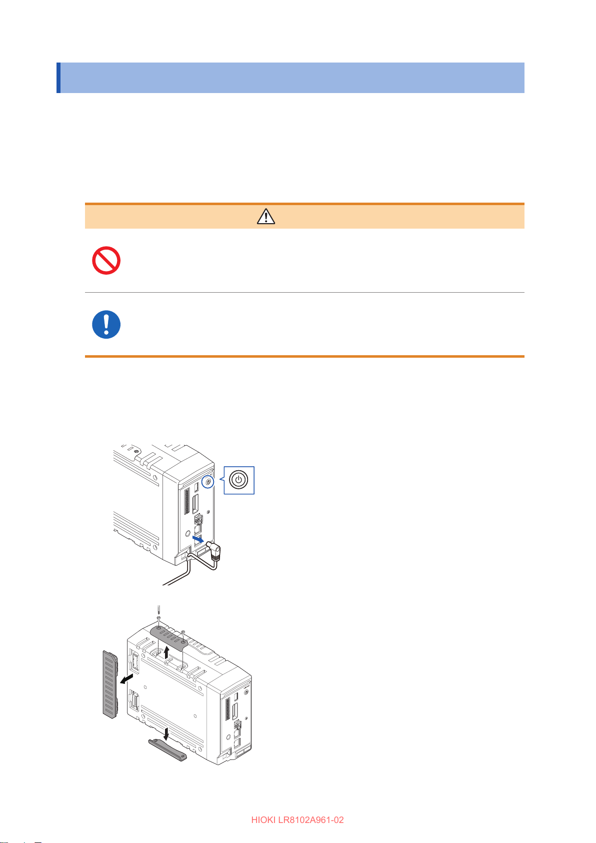
Connecting the Measurement Modules
HIOKI LR8102A961-02
2.2 Connecting the Measurement Modules
Up to ten optional measurement modules can be connected to one instrument.
Up to a total of ten M7100 or M7102 modules can be connected to a single instrument.
Up to four M7103 modules can be connected to a single instrument.
When using M7103, AC power supply module M1100 is required. ( p. 51).
Determine the number of measurement modules to be connected according to the number of
channels required for the measurement.
WARNING
When no measurement module is connected, do not remove the
connector cover.
Doing so could cause the operator to experience an electric shock or damage the
instrument and measurement modules.
Before connecting or disconnecting the measurement modules, turn
OFF the instrument and remove the cables.
Failure to do so could cause the operator to experience an electric shock or damage
the instrument and measurement modules.
Connecting the Measurement Modules to the Instrument
Applicable modules: M7100, M7102 or M7103
Required items: Phillips screwdriver (No. 2)
Turn OFF the instrument and remove the AC
1
adapter.
Remove the connector covers.
2
46
Page 47
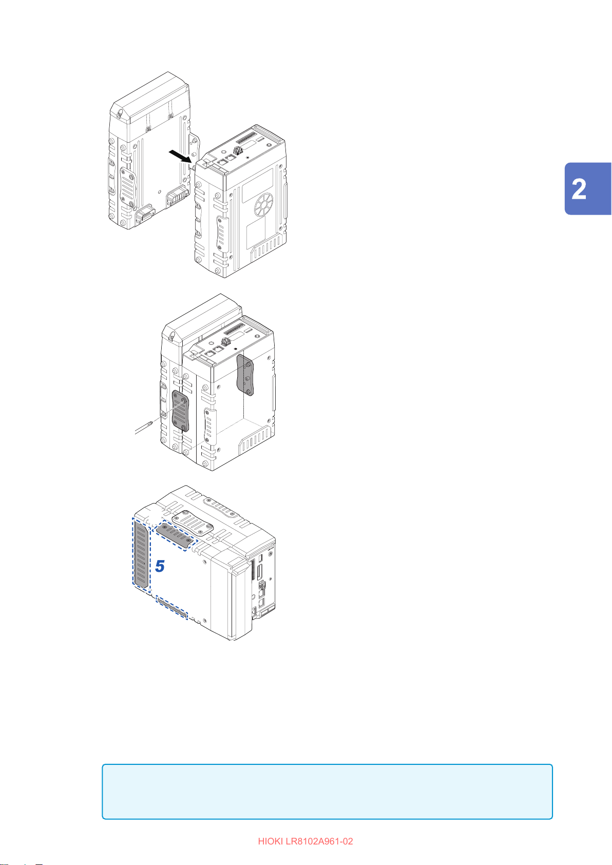
Connecting the Measurement Modules
HIOKI LR8102A961-02
Connect a measurement module to the
3
connector of the instrument.
Tighten the captive screws (4 locations).
4
Tighten the screws at 0.6 N•m.
Connection (Preparation for Measurements)
Reattach the connector covers removed in 2.
5
Tighten the screws at 0.6 N•m.
Connecting an additional measurement module
An additional measurement module can be installed on the left side of the rst measurement
module.
Connect the additional measurement module in the same way as you connected the rst
measurement module to the instrument.
Neither M7100 nor M7102 can be connected between M7103 and the instrument.
IMPORTANT
Channel settings may be initialized when there is a change in connected modules. Please check
settings.
47
Page 48
Connecting the AC adapter
HIOKI LR8102A961-02
2.3 Connecting the AC adapter
Connect the power cord to the AC adapter, and then connect the AC adapter to an outlet.
Make sure to use the optional Z1016 AC Adapter (2-pole grounding power cord included).
Before connecting, make sure to read “Handling of cords and cables” (p. 54).
In addition, turn OFF the instrument before connecting or disconnecting the AC adapter.
WARNING
When supplying the power from a commercial power supply to the
instrument, use the optional Z1016 AC Adapter (2-pole grounding power
cord included).
Use the AC adapter at the rated supply voltage and the rated powersupply frequency.
Rated supply voltage: 100 V AC to 240 V AC (voltage uctuation within ±10%)
Rated power-supply frequency: 50/60 Hz
Turn OFF the instrument before connecting the AC adapter to the
instrument and the commercial power supply.
Failure to do so could cause the operator to experience an electric shock.
Connect the power cord of the AC adapter to a 2-pole grounding outlet.
Connecting the power cord to an ungroundable outlet could cause the operator to
experience an electric shock.
CAUTION
When using the AC power supply module, do not use the AC adapter or
external power supply.
The instrument can be damaged.
Before connecting the plug to the outlet, connect the output plug of the AC
adapter to the instrument.
Failure to do so could damage the instrument.
When unplugging the power cord from the outlet or instrument, pull on the
plug (not the cord).
The cable may be broken or the output terminal may be damaged.
48
Page 49
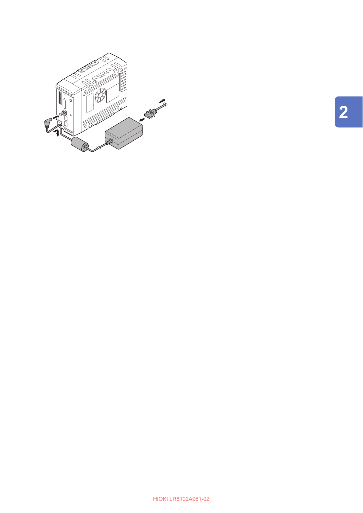
Connecting the AC adapter
HIOKI LR8102A961-02
Supply the power to the instrument using the AC adapter (AC driven)
Connect the power cord to the Z1016 AC
1
Adapter.
Connect the output plug of the AC adapter to
2
the power supply terminal of the instrument.
To prevent the plug from coming o, press the
3
output cord of the AC adapter cable into the
cable hook of the instrument.
Connect the plug of the power cord to the
4
outlet.
Connection (Preparation for Measurements)
49
Page 50
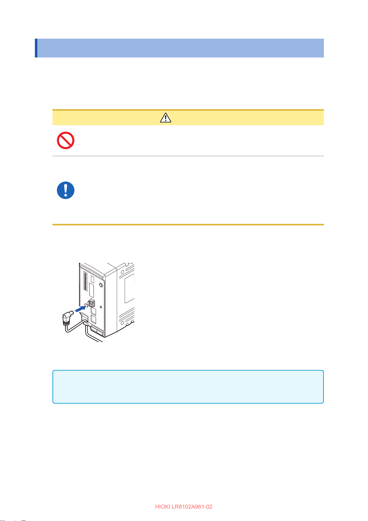
Connecting an External Power Supply
HIOKI LR8102A961-02
2.4 Connecting an External Power Supply
A DC power supply can be used as an external power supply for the instrument.
Be sure to use the optional L1012 Power Cable.
Before connecting, make sure to read “Handling of cords and cables” (p. 54).
In addition, turn OFF the instrument before connecting or disconnecting the power cable.
CAUTION
When using the AC power supply module, do not use the AC adapter or
external power supply.
The instrument can be damaged.
Use the external power supply at the rated supply voltage.
Rated supply voltage: 10 V DC to 30 V DC
Turn OFF the instrument before connecting the power cord.
Pay attention to the polarity and correctly connect the terminals of the power
cord.
Failure to do so could damage the instrument.
Supply the power to the instrument from an external power supply (DC driven)
Connect the plug of the power cord to the
1
power supply terminal of the instrument.
To prevent the plug from coming o, press
2
the power cord into the cable hook of the
instrument.
Pay attention to the polarity and connect the
3
terminals of the power cord to the DC power
supply.
IMPORTANT
When a power cord that is 3 m or longer is connected, the instrument may be aected by factors
in the EMC environment, such as exogenous noise.
50
Page 51
Connecting the AC Power Supply Module
HIOKI LR8102A961-02
2.5 Connecting the AC Power Supply Module
Install the optional AC power supply module M1100 onto the instrument.
The AC power supply module is required only when using the M7103 Power Measurement Module.
Before connecting, make sure to read “Handling of cords and cables” (p. 54).
Also, turn OFF the instrument before connecting the AC power supply module.
WARNING
Use the AC power supply module at the rated supply voltage and the
rated power-supply frequency.
Rated supply voltage: 100 V to 240 V AC (voltage uctuation within ±10%)
Rated power-supply frequency: 50 Hz/60 Hz
Turn OFF the instrument before connecting the AC power supply
module to the instrument and the commercial power supply.
Failure to do so could cause the operator to experience an electric shock.
Connect the power cord of the AC power supply module to a 3-prong
grounded-type (2-pole) power outlet.
Connection (Preparation for Measurements)
Connecting the power cord to an ungroundable outlet could cause the operator
to experience an electric shock.
CAUTION
When using the AC power supply module, do not use the AC adapter or
external power supply.
The instrument can be damaged.
Before connecting the plug to the outlet, connect the output plug of the AC
power supply module to the instrument.
Failure to do so could damage the instrument.
When unplugging the power cord from the outlet or instrument, pull on the
plug (not the cord).
The cable may be broken or the output terminal may be damaged.
51
Page 52
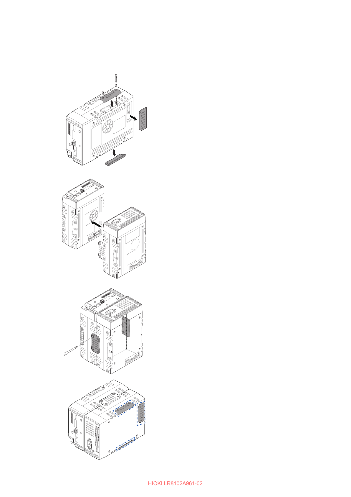
Connecting the AC Power Supply Module
HIOKI LR8102A961-02
Connecting the AC power supply module to the instrument
Applicable module: M1100
Required items: Phillips screwdriver (No. 2)
Remove the connector cover.
1
Loosen the captive screws. (4 locations)
2
Connect the AC power supply module to the
3
connector of the instrument.
Tighten the captive screws. (4 locations)
4
Tighten the screws at 0.6 N•m.
Reattach the connector cover removed in step
5
.
Tighten the screws at 0.6 N•m.
52
Page 53
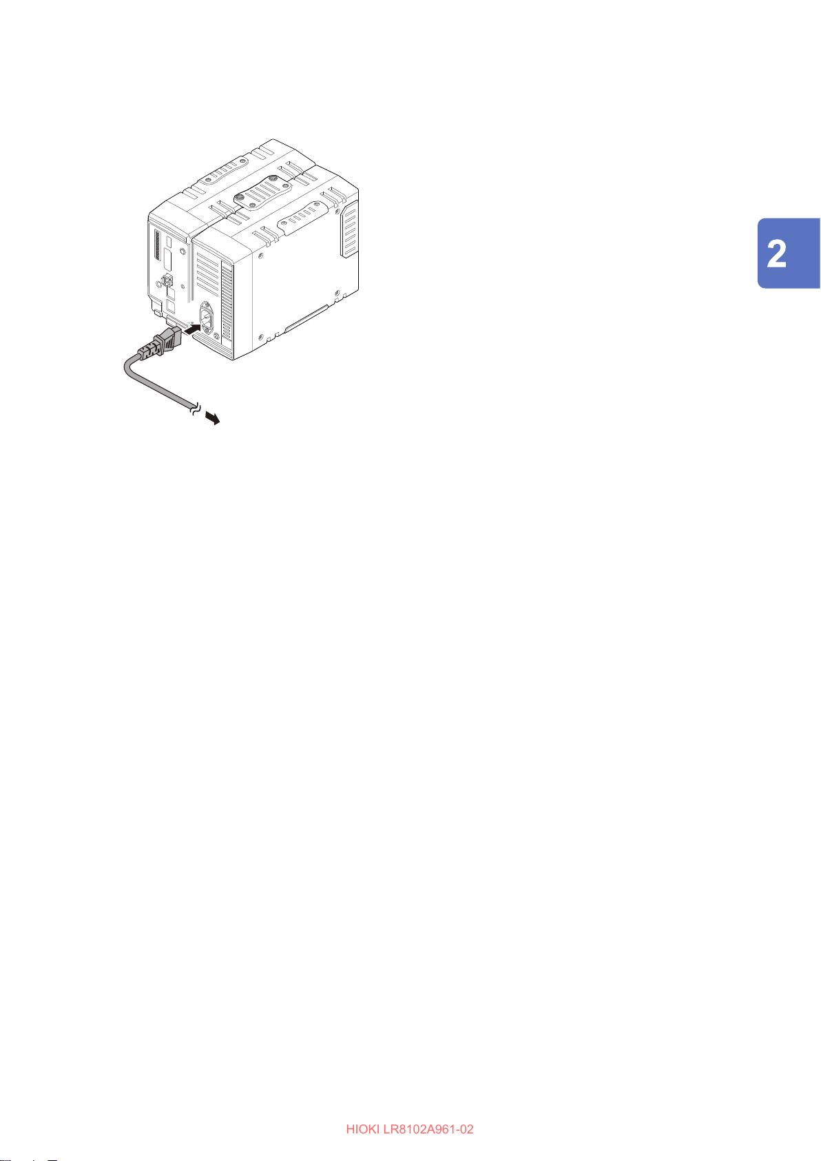
Connecting the AC Power Supply Module
HIOKI LR8102A961-02
Supplying the power to the instrument using the M1100 AC power supply module
(AC driven)
Connect the provided power cord to the power
1
inlet of the AC power supply module.
Connect the plug of the power cord to the
2
outlet.
Connection (Preparation for Measurements)
53
Page 54
Connecting Cables
HIOKI LR8102A961-02
2.6 Connecting Cables
Handling of cords and cables
Hang the measurement cables lower than the instrument.
Otherwise, water or liquid could enter the instrument along the measurement cables,
damaging the instrument and causing bodily injury.
Follow the procedure below before wiring the measurement terminals
or turning ON the instrument.
1. Shut down the power of the measurement line.
2. Turn OFF the instrument and other devices.
3. Remove the measurement target.
4. Close the terminal block cover.
Use the specied wiring materials. Alternatively, use wiring materials
with sucient dielectric strength and current capacity.
WARNING
Otherwise, accidents due to electric shock or short circuit may occur.
Securely connect the measurement cables to the input terminals.
Loose terminals could result in increased contact resistance, causing the product to
become hot or burn up or resulting in bodily injury or re.
CAUTION
Do not route cords between other objects or step on them.
Doing so could damage the insulation and cause the operator to experience an
electric shock.
Do not input voltage that exceeds the specied rating between the channels.
Semiconductor relays are used for the insulation between the channels of the
measurement module. When any voltage that exceeds the specied rating is applied,
such as lightning surges, the semiconductor relays can fail with a short-circuit.
IMPORTANT
• When a cable that is 3 m or longer is connected, measurement may be aected by factors in
the EMC environment, such as exogenous noise. Position the cable away from the power line
or ground cable.
• When the cable is connected in parallel to other equipment, measurement values may vary. If
the measurement cable is to be connected in parallel, make sure to check the operation before
use.
54
Page 55
Connecting Cables
HIOKI LR8102A961-02
When connecting to the input terminal
DANGER
Do not leave the input cables connected in an environment where there
is a possibility of surges exceeding the dielectric strength.
Doing so may damage the instrument, resulting in serious bodily injury.
WARNING
Follow the procedure below before wiring the input terminal.
1. Turn o the power of this instrument and the instrument to be connected.
2. Discharge static electricity from your body.
Failure to do so could cause the operator to experience an electric shock or damage
the instrument.
When wiring with a crimped terminal, use an insulation coated terminal with the following size for
M3 screws.
Connection (Preparation for Measurements)
6 mm or less 6 mm or less
When wiring the external control terminal
WARNING
Follow the procedure below before wiring the external control terminal.
1. Turn o the power of this instrument and the instrument to be connected.
2. Discharge static electricity from your body.
3. Check that the signal does not exceed the external input and output rating.
4. Properly isolate this instrument and the instrument to be connected to the EXT. I/O
connector terminal.
Failure to do so could cause the operator to experience an electric shock or damage
the instrument.
CAUTION
Do not short or input any voltage to the output unit.
The instrument can be damaged.
Ensure that there is no potential dierence between the ground of the external
control terminal and the ground of the connection target.
Failure to do so could damage the connection target and the instrument.
The ground of the external control terminal and the ground of the instrument are
common and they are not isolated from each other.
When using a twisted pair wire for the measurement cable, take care not to allow the measurement
cable to contact adjacent measurement cables or terminals.
55
Page 56
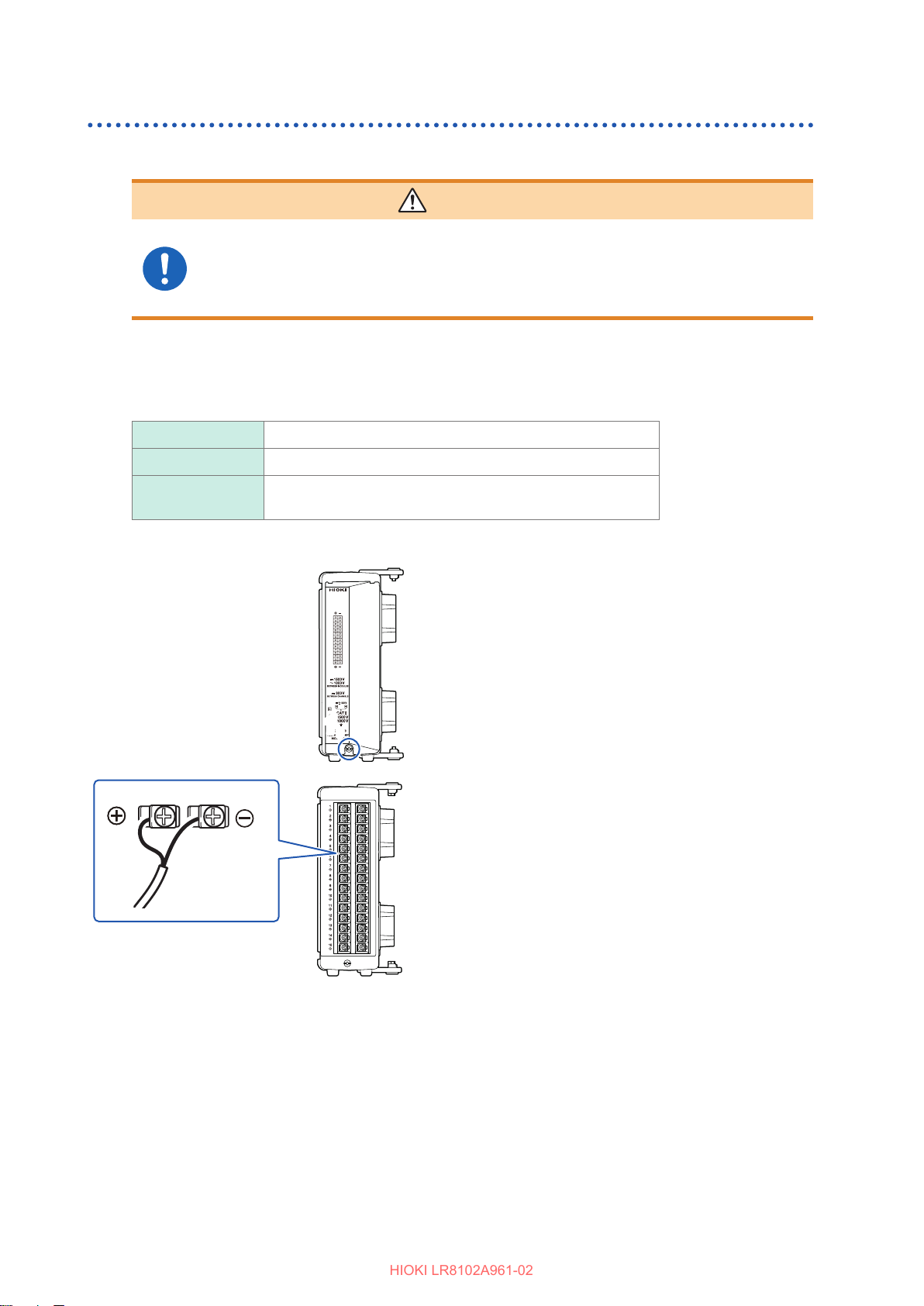
Connecting Cables
HIOKI LR8102A961-02
Wiring the voltage cable and thermocouple
Connection to a screw type terminal block
WARNING
Use the dedicated screws to x the wiring to a screw type terminal
block.
Using screws other than the dedicated ones could cause the operator to experience
an electric shock or damage the instrument.
Applicable module: M7100
Required items: Phillips screwdriver (No. 2), input cable or thermocouple
Recommended wire diameter
Solid ø0.2 mm to ø1.29 mm (AWG32-16)
2
Stranded 0.03 mm
to 1.38 mm2 (AWG32-16)
Standard stripped
wire length
10 mm
1
6
Remove the screw for the terminal block
1
cover.
Open the terminal block cover.
2
Loosen the terminal block screws. Insert the
3
wires of the cable as shown in the gure and
tighten the screws.
Tighten the terminal block screws at 0.5 Nm.
The color scheme for the cable sheath varies with
dierent countries and manufacturers. Conrm
the colors before connecting the cable.
Connect the cable to the measurement target.
4
Close the terminal block cover.
5
56
Tighten the screw for the terminal block cover.
6
Page 57
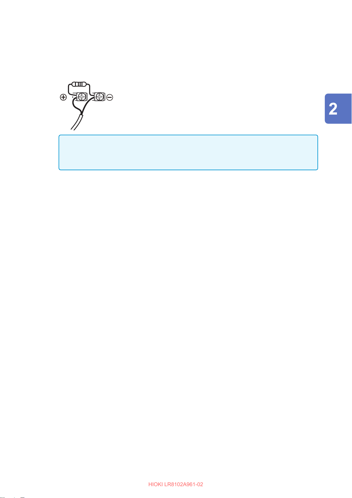
Connecting Cables
HIOKI LR8102A961-02
When measuring an instrumentation device (inputting a current of 4-20 mA), connect a 250 Ω shunt
resistor as shown in the gure below. For the measurement of instrumentation devices, see “When
measuring the output from an instrumentation device” (p. 121).
Shunt resistor
250
Ω
IMPORTANT
Be sure to x the terminal block cover using the screw.
If the terminal block cover is not closed, the measured values may be aected.
Connection (Preparation for Measurements)
57
Page 58
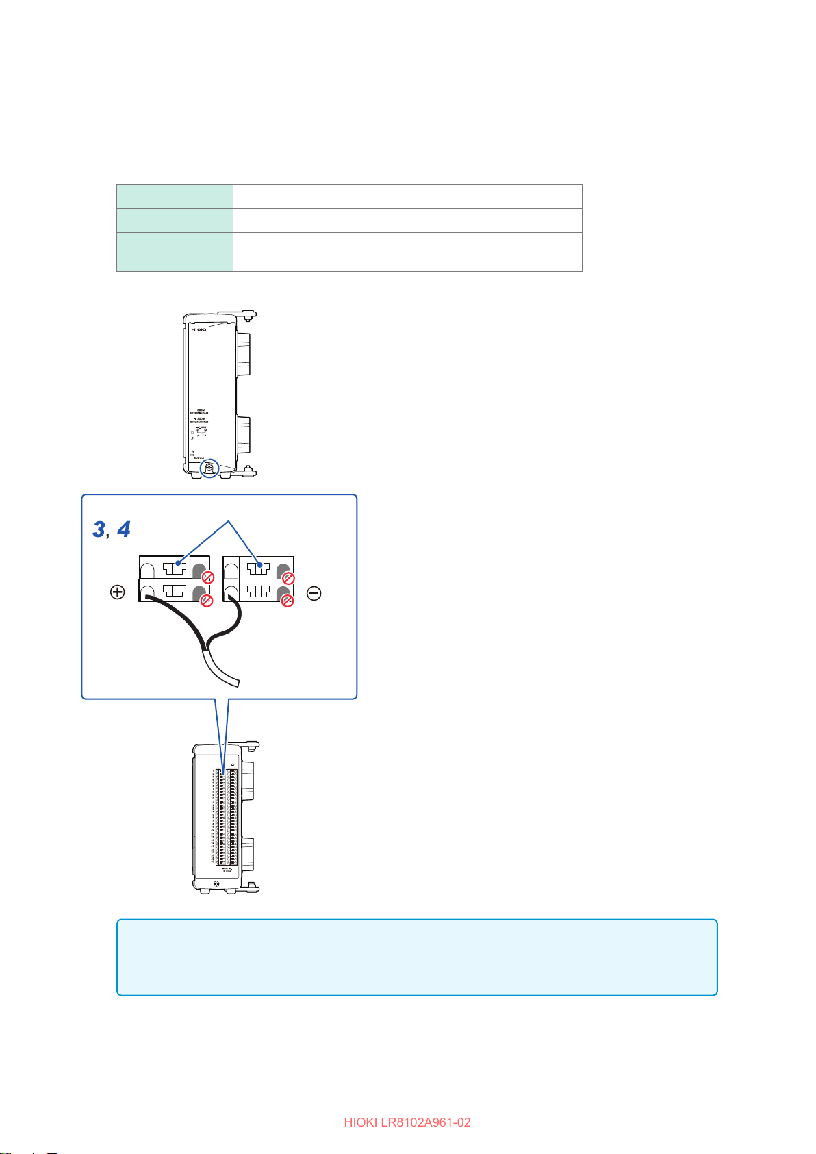
Connecting Cables
HIOKI LR8102A961-02
Connecting to a push-button type terminal block
Applicable module: M7102
Required items: Flat-head screwdriver (blade edge width 2.6 mm), input cable or thermocouple
Recommended wire diameter
Solid ø0.32 mm to ø1.29 mm (AWG26-16)
2
Stranded 0.2 mm
to 0.52 mm2 (AWG24-20)
Standard stripped
wire length
3
4
9 mm
Terminal button
Remove the screw for the terminal block
1
cover.
Open the terminal block cover.
2
Press the terminal button with a at-head
3
screwdriver and insert the wire of the cable
into the terminal hole.
The color scheme for the cable sheath varies with
dierent countries and manufacturers. Conrm
the colors before connecting the cable.
Remove the at-head screwdriver from the
4
button.
The cable is locked. Pull the cable gently and
conrm that the cable will not come out.
Connect the cable to the measurement target.
5
Close the terminal block cover.
6
Tighten the screw for the terminal block cover.
7
IMPORTANT
Be sure to x the terminal block cover using the screw.
If the terminal block cover is not closed, the measured values may be aected.
58
Page 59
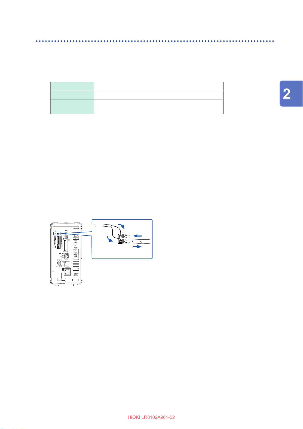
Connecting Cables
HIOKI LR8102A961-02
Wiring for the pulse input
Connect a cable to the external control terminal.
Required items: Flat-head screwdriver (blade edge width 2.6 mm), input cable (pulse measurement)
Recommended wire diameter
Solid ø0.32 mm to ø0.81 mm (AWG28-20)
2
Stranded 0.08 mm
to 0.32 mm2 (AWG28-20)
Standard stripped
wire length
Turn forward the external control terminal on the front of the instrument.
1
Press the button of the PULSE terminal with a at-head screwdriver.
2
While holding down the button, insert the plus (+) cable into the terminal hole.
3
Remove the at-head screwdriver from the button.
4
The cable is locked. Pull the cable gently and conrm that the cable will not come out.
Press the button of the GND terminal with a at-head screwdriver.
5
Five ground terminals are available. The cable can be connected to any of the ground terminals.
While holding down the button, insert the minus (-) cable into the terminal hole.
6
Remove the at-head screwdriver from the button.
7
The cable is locked. Pull the cable gently and conrm that the cable will not come out.
10 mm
Connection (Preparation for Measurements)
59
Page 60
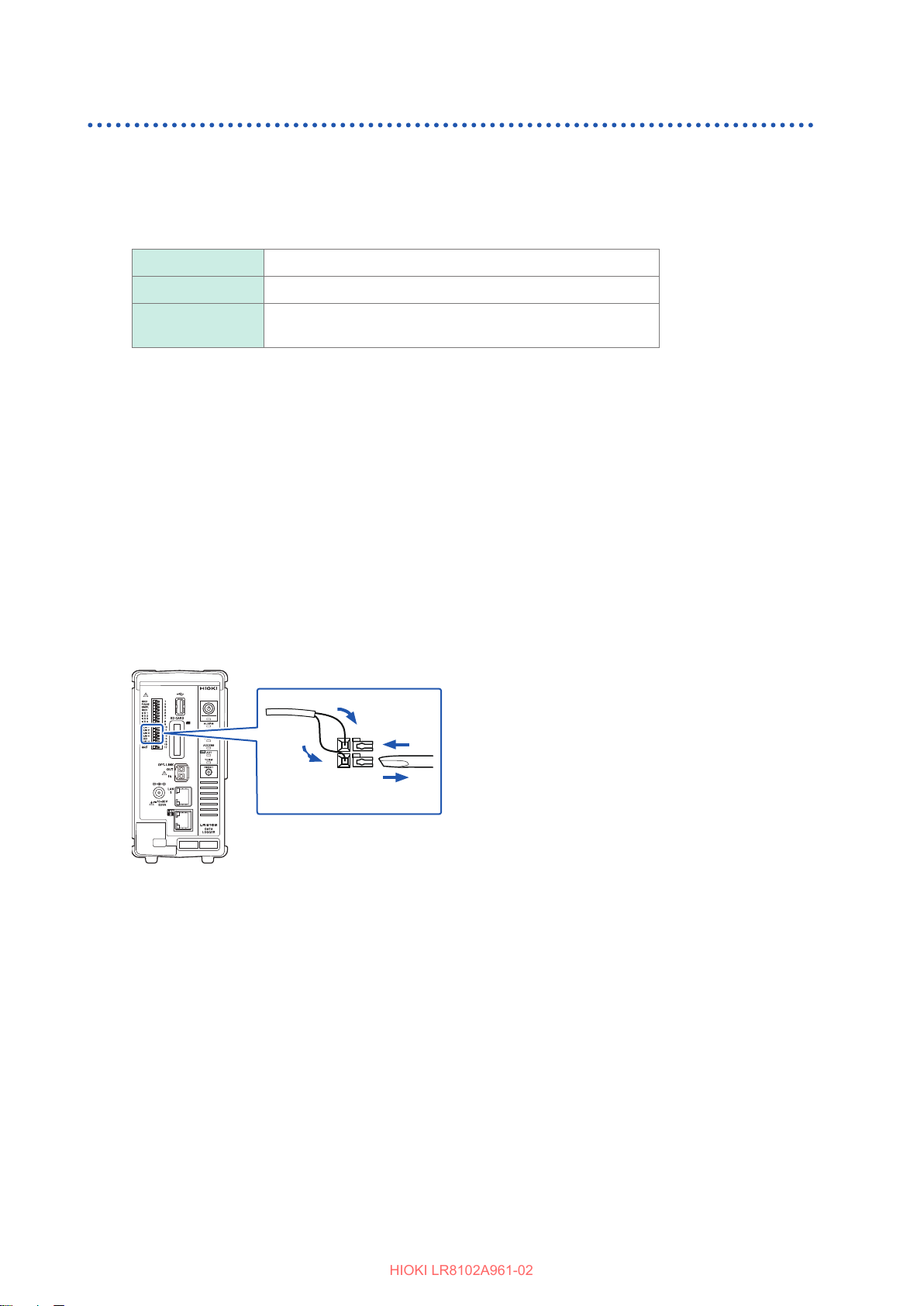
Connecting Cables
HIOKI LR8102A961-02
Wiring for the alarm output
Connect a cable to the external control terminal.
Required items: Flat-head screwdriver (blade edge width 2.6 mm), output cable (alarm output)
Recommended wire diameter
Solid ø0.32 mm to ø0.81 mm (AWG28-20)
2
Stranded 0.08 mm
to 0.32 mm2 (AWG28-20)
Standard stripped
wire length
Turn forward the external control terminal on the front of the instrument.
1
Press the button of the ALM 1 (or ALM 2 to ALM 4) terminal with a at-head screwdriver.
2
While holding down the button, insert the cable into the terminal hole.
3
Remove the at-head screwdriver from the button.
4
The cable is locked. Pull the cable gently and conrm that the cable will not come out.
Press the button of the GND terminal with a at-head screwdriver.
5
Five ground terminals are available. The cable can be connected to any of the ground terminals.
While holding down the button, insert the cable into the terminal hole.
6
Remove the at-head screwdriver from the button.
7
The cable is locked. Pull the cable gently and conrm that the cable will not come out.
10 mm
60
Page 61
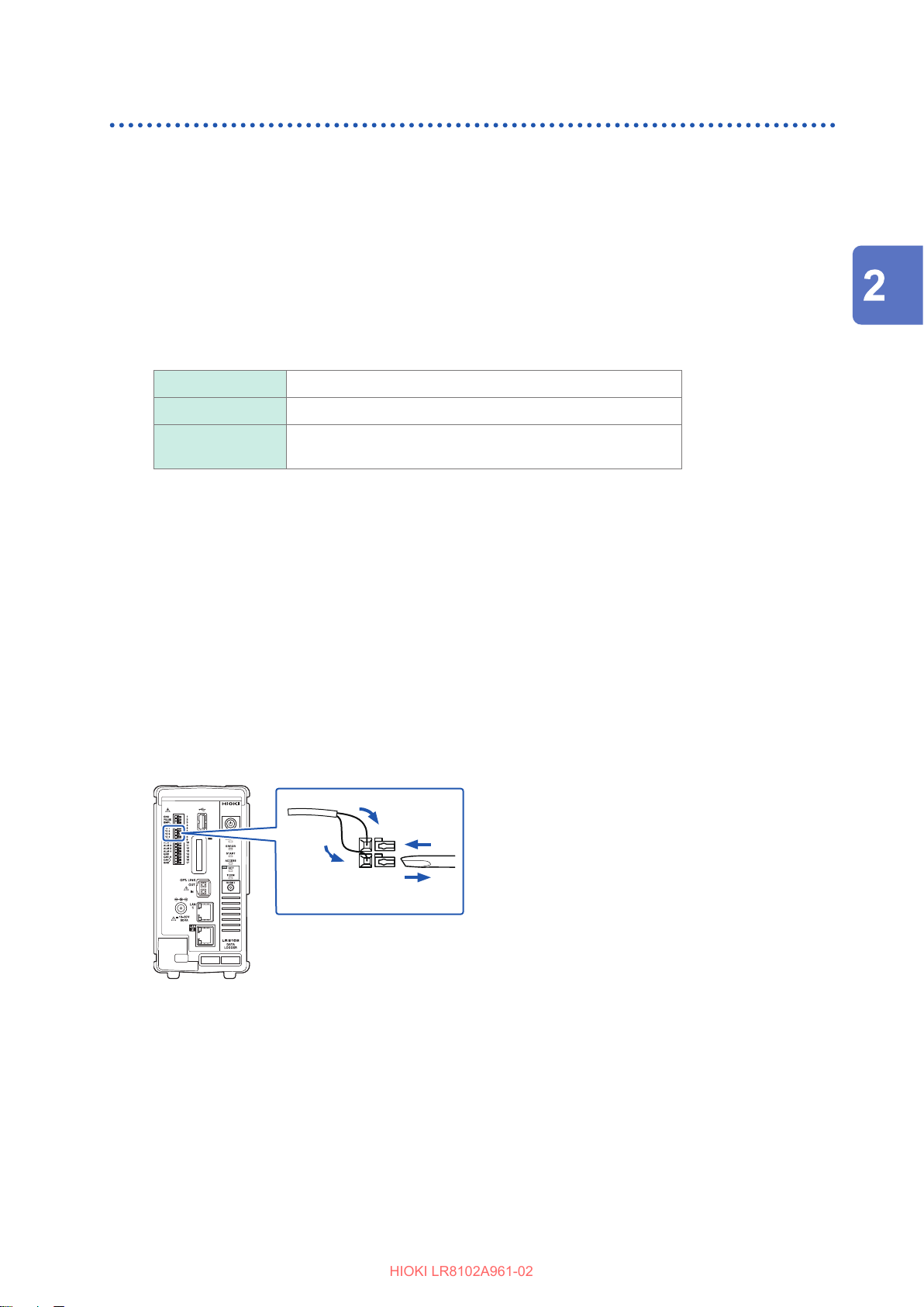
Wiring for external control
HIOKI LR8102A961-02
Connect a cable to the external control terminal.
• External input: Allows you to control the start and stop of the measurement and input the trigger
signals.
See “5.6 Applying External Trigger” (p. 214) and
“11.2 Setting the External Input and Output (I/O) Terminals” (p. 305).
• External output: Signals can be output when the trigger is activated.
See “11.2 Setting the External Input and Output (I/O) Terminals” (p. 305).
Connecting Cables
Required items: Flat-head screwdriver (blade edge width 2.6 mm), input cable (pulse measurement)
Recommended wire diameter
Solid ø0.32 mm to ø0.81 mm (AWG28-20)
2
Stranded 0.08 mm
Standard stripped
wire length
Turn forward the external control terminal on the front of the instrument.
1
Press the button of the I/O 1 (or I/O 2 to I/O 4) terminal with a at-head screwdriver.
2
While holding down the button, insert the cable into the terminal hole.
3
Remove the at-head screwdriver from the button.
4
The cable is locked. Pull the cable gently and conrm that the cable will not come out.
Press the button of the GND terminal with a at-head screwdriver.
5
Five ground terminals are available. The cable can be connected to any of the ground terminals.
While holding down the button, insert the cable into the terminal hole.
6
Remove the at-head screwdriver from the button.
7
The cable is locked. Pull the cable gently and conrm that the cable will not come out.
10 mm
to 0.32 mm2 (AWG28-20)
Connection (Preparation for Measurements)
61
Page 62
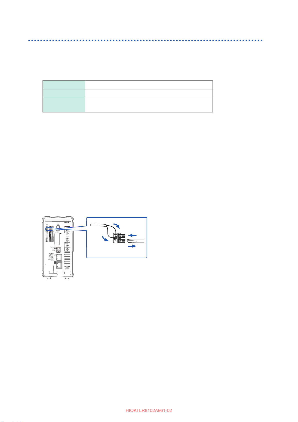
Connecting Cables
HIOKI LR8102A961-02
Wiring for the external sampling
Connect a cable to the external control terminal.
Required items: Flat-head screwdriver (blade edge width 2.6 mm), input cable (pulse measurement)
Recommended wire diameter
Solid ø0.32 mm to ø0.81 mm (AWG28-20)
2
Stranded 0.08 mm
to 0.32 mm2 (AWG28-20)
Standard stripped
wire length
Turn forward the external control terminal on the front of the instrument.
1
Press the button of the SMPL terminal with a at-head screwdriver.
2
While holding down the button, insert the plus (+) cable into the terminal hole.
3
Remove the at-head screwdriver from the button.
4
The cable is locked. Pull the cable gently and conrm that the cable will not come out.
Press the button of the GND terminal with a at-head screwdriver.
5
Five ground terminals are available. The cable can be connected to any of the ground terminals.
While holding down the button, insert the minus (-) cable into the terminal hole.
6
Remove the at-head screwdriver from the button.
7
The cable is locked. Pull the cable gently and conrm that the cable will not come out.
10 mm
62
Page 63
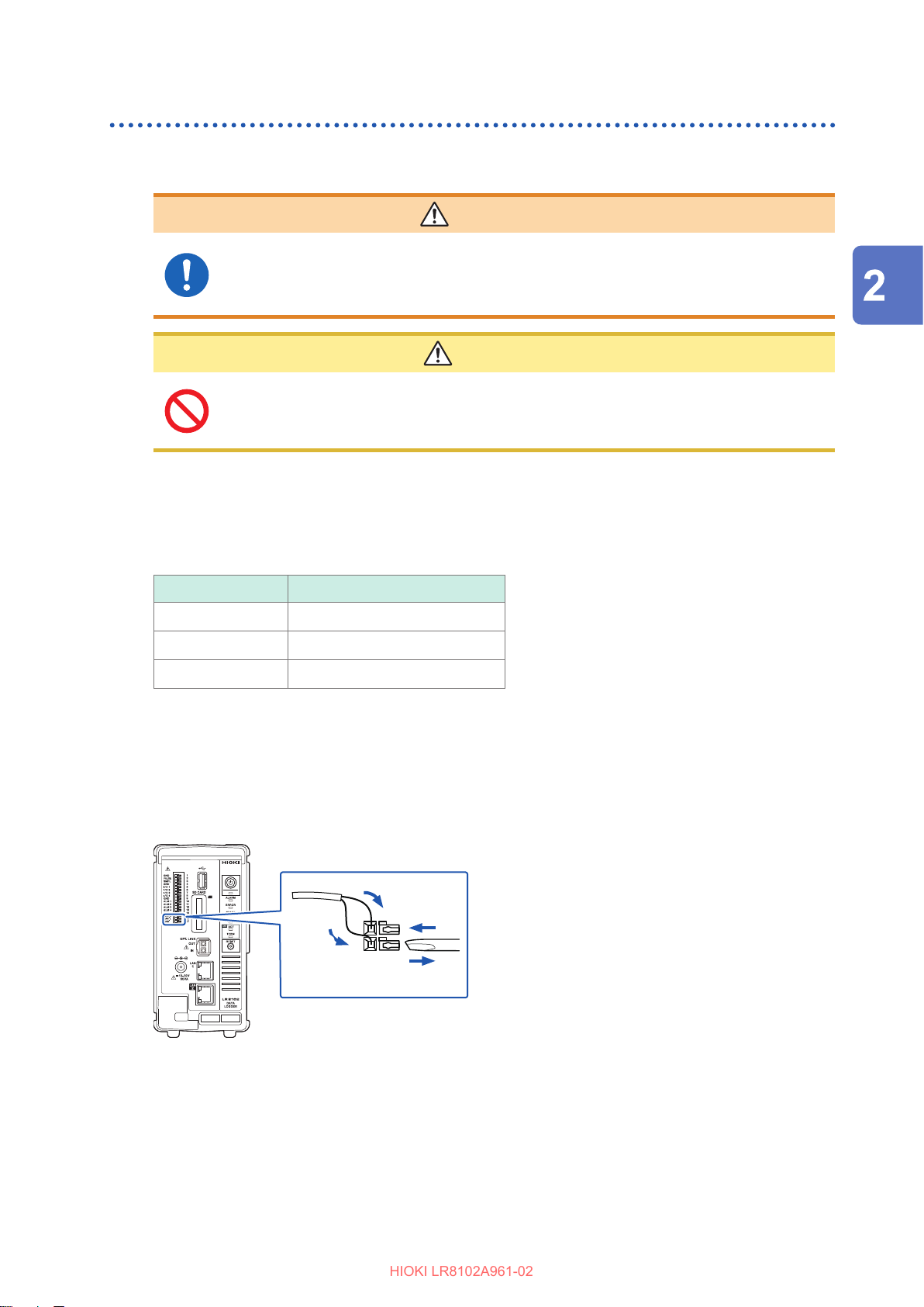
Wiring the CAN cable (LR8102 only)
HIOKI LR8102A961-02
Required items: Flat-head screwdriver (blade edge width 2.6 mm), 9713-01 CAN cable
WARNING
Turn OFF all devices before connecting or disconnecting interface
connectors.
Failure to do so could cause the operator to experience an electric shock.
CAUTION
Do not unplug the input cable while the instrument is sending or receiving
data.
Doing so could cause an unexpected error on the CAN bus.
Connecting Cables
Connection (Preparation for Measurements)
Turn forward the external control terminal on the front of the instrument.
1
Press the terminal button with a at-head screwdriver and insert the wire of the cable into
2
the terminal hole.
Terminal Cable
CAN_H CAN_H (red)
CAN_L CAN_L (green)
GND CAN_GND (black)
Five ground terminals are available. The cable can be connected to any of the ground terminals.
Remove the at-head screwdriver from the button.
3
The cable is locked.
Pull the cable gently and conrm that the cable will not come out.
4
63
Page 64
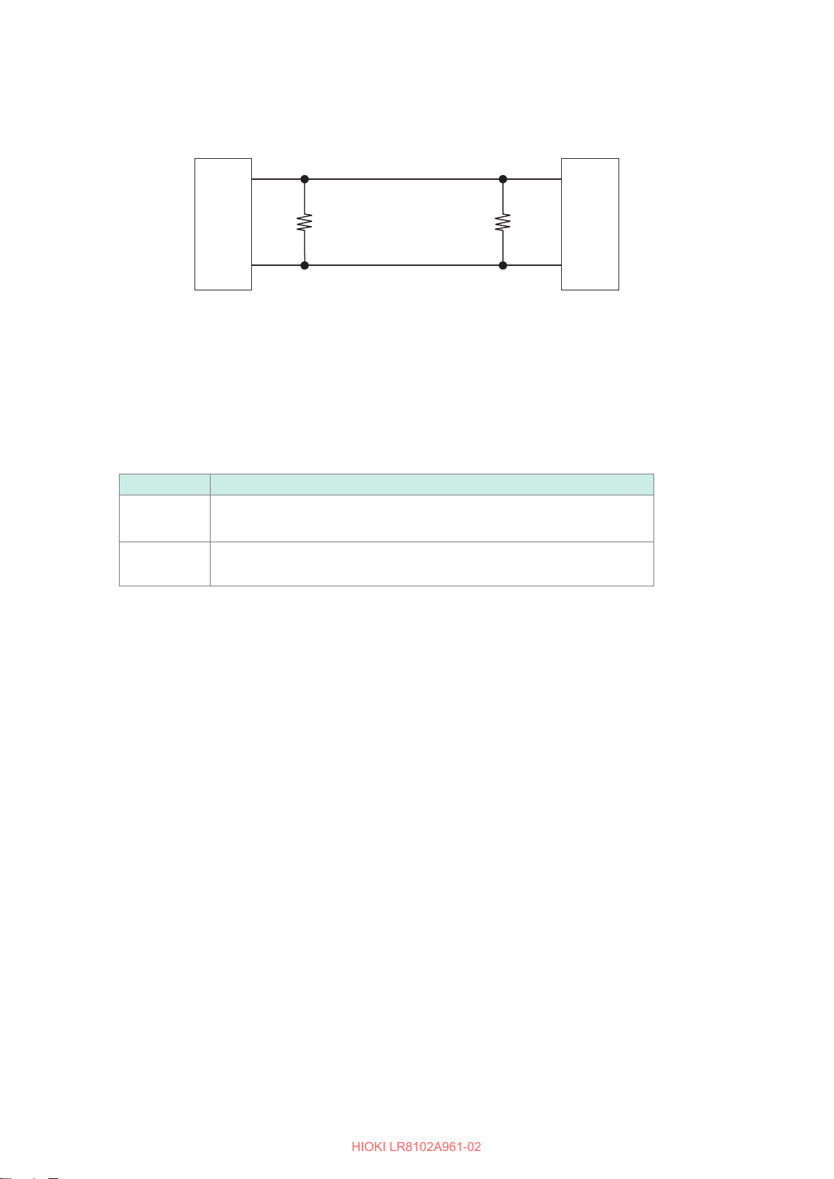
Connecting Cables
HIOKI LR8102A961-02
Terminator setting
• The CAN communication system requires 120 Ω terminators on both sides of the bus.
Device 1 Device 2
CAN_H
Ω
120
CAN_L
Ω
120
• If the terminator is set to ON, the 120 Ω resistors are inserted between the dierential signals of
the CAN bus inside the LR8102.
See “14.11 Conguration of Input Circuit” (p. 426).
Description of the LED operations
The operation status of the CAN can be checked with the LEDs.
LED Status
ACT LED • Blinking: When the output signal is received properly*
• Lamp OFF: When there is no output target*
TERM LED • Lit: When the terminator is ON
• Lamp OFF: When the terminator is OFF
*1. The LED blinks if any one of the set CAN communications is performed in accordance with the conditions.
See CAN Editor Instruction Manual“6.3 Receive CAN Data”.
*2. The conditions for the CAN communication may not be satised or the CAN port may not be connected
with the CAN bus correctly.
See CAN Editor Instruction Manual “5.4 Setting the Communication Method of the CAN Unit”.
Check that there is a channel for which the output is ON.
See CAN Editor Instruction Manual “7.5 Selecting the Channel to be Output”.
2
1
64
Page 65
Wiring the optical connection cable (LR8102 only)
HIOKI LR8102A961-02
CAUTION
Do not connect or disconnect connectors while the instrument is powered ON.
Doing so could damage the instrument.
• Do not bend or pull the optical connection cables.
Bending or pulling the cables may result in cable breakage or damaged insulation,
causing the instrument to malfunction.
Using the optional L6101 or L6102 Optical Connection Cable to connect instruments in a daisy
chain enables synchronized measurement with up to 10 units.
Since the units are synchronized using optic ber without electrical signals, instruments with
dierent ground potential can be connected without any problems.
IMPORTANT
• Up to 10 units can be synchronized. Eleven or more units cannot be synchronized.
• The cable can only be connected with the instrument. Connecting the cable with other devices
may cause a malfunction.
Connecting Cables
Connection (Preparation for Measurements)
Required items: Instruments (2 to 10 units), L6101 or L6102 Optical Connection Cable (the same
number of cables as the instruments)
Make sure that the instruments are turned o.
1
Connect the OUT terminal of the optical synchronization connector of the primary unit and
2
the IN terminal of the optical synchronization connector of the secondary unit using an
optical connection cable.
For multiple secondary units
3
Connect the OUT terminal of the optical synchronization connector of the secondary unit
and the IN terminal of the optical synchronization connector of another secondary unit using
an optical connection cable.
Repeat this step until all the IN terminals of the optical synchronization connectors of the secondary units are
connected.
65
Page 66
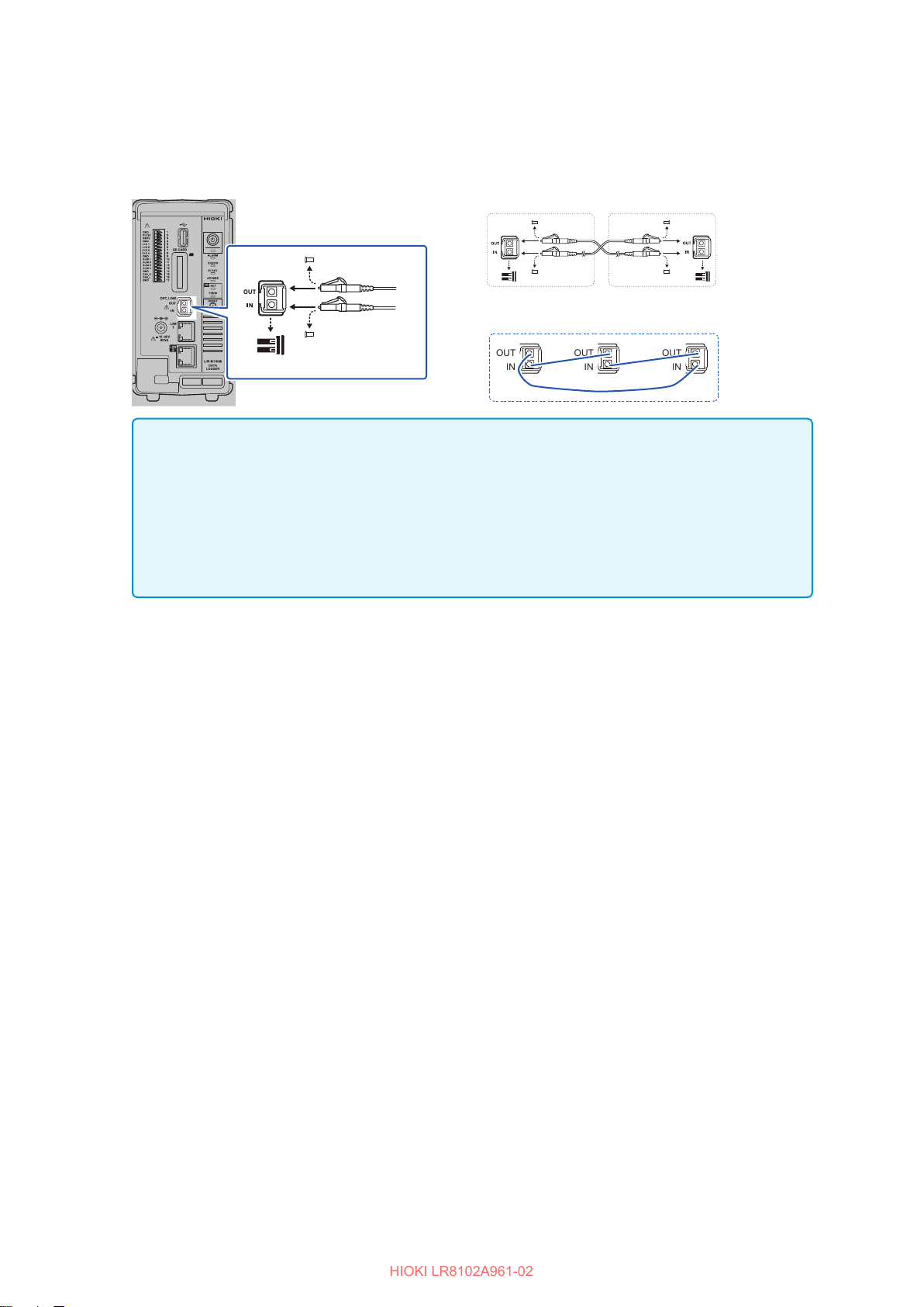
Connecting Cables
HIOKI LR8102A961-02
There is a secondary unit for which the OUT terminal of the optical synchronization
4
connector remains unconnected with an optical connection cable. Connect the unconnected
OUT terminal and the IN terminal of the optical synchronization connector of the primary
unit.
When two units are connected
When three units are connected
Remove the
protective caps
OUT
IN
OUT
IN
OUT
IN
IMPORTANT
• Never unplug the cable during the synchronization control. The synchronization may fail.
• A synchronization error occurs if either of the power supplies for the primary and secondary
units is turned OFF.
• Use primary and secondary units with the same version. Using dierent versions results in a
synchronization error.
• Even when connecting instruments with a synchronization cable, LAN cables must be
connected to all instruments to allow conguration of their settings.
66
Page 67
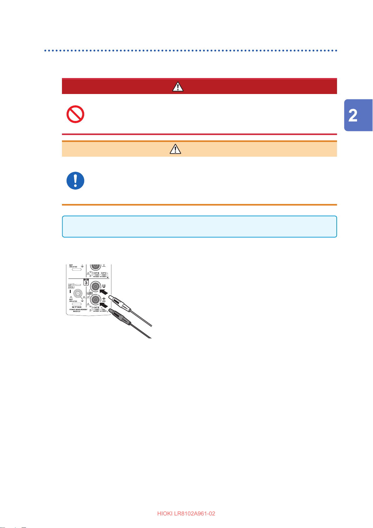
Connecting Cables
HIOKI LR8102A961-02
Connecting the voltage cords
Connect the voltage cords (option) to the voltage input terminals. Connect the necessary number of
cords for the lines to be measured and their wiring.
DANGER
Do not short-circuit the two wires of the measurement line using the
metallic part at the tip of the voltage cord clip.
Doing so can cause arc ash, resulting in serious bodily injury or damage to the
device or other equipment.
WARNING
When using the instrument, make sure to use the connection cord
specied by our company.
Using any cords other than that specied could result in serious bodily injury or short
circuit.
Reference: “Voltage measurement options” (p. 40)
Connection (Preparation for Measurements)
IMPORTANT
To ensure correct measurement, securely insert the voltage cords as far as they will go.
Turn OFF the instrument.
1
Insert the red voltage cord into voltage input terminal
2
“U”.
Insert the black voltage cord into voltage input
3
terminal “±”.
67
Page 68
Connecting Cables
HIOKI LR8102A961-02
Connecting the current sensor (current input)
Connect the current sensor to the
Do not use the current sensor for measuring any circuits that exceed
the maximum rated line-to-ground voltage *
Do not use over bare conductors.
Doing so could result in serious bodily injury or short circuit.
*1. For the maximum rated line-to-ground voltage of the current sensor, see the
instruction manual supplied with the current sensor.
Be sure to turn OFF each hardware before connecting the pass-through
type current sensor, such as CT6875.
Failure to do so could cause the operator to experience an electric shock or short
circuit.
Do not connect or disconnect connectors while the instrument is powered ON.
current sensor
DANGER
WARNING
CAUTION
terminal.
1
.
The sensor can be damaged.
When disconnecting the cable, be sure to release the lock rst, and then pull
on the connector end (not the cable).
Failure to do so could cause damage to the BNC connector or joint section.
68
Page 69
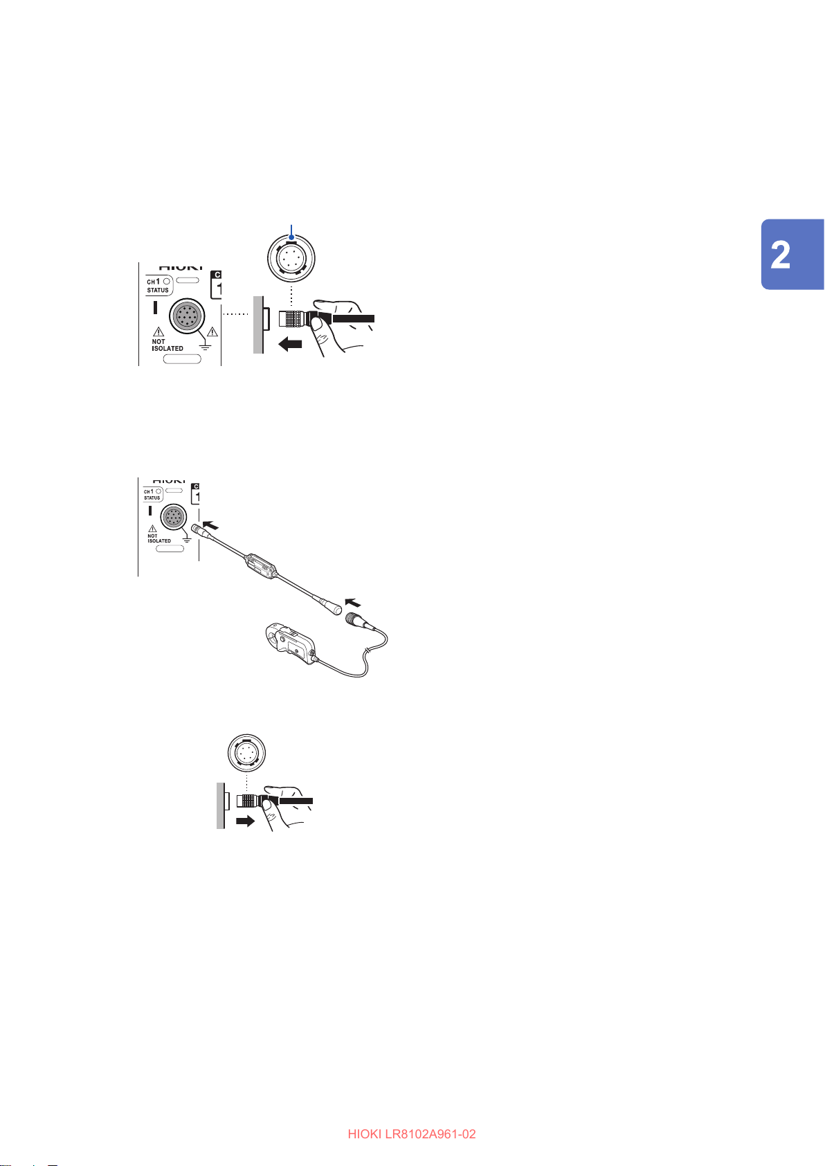
Connecting Cables
HIOKI LR8102A961-02
For metal connectors
Connectors of the 9709-05, CT6860-05 series, and CT6840-05 series can be directly connected to
the current sensor terminal.
Connectors for current sensors with “-05” in the product model are mode of metal.
Hold the connector
with the wide area
facing upward
For resin connectors
Connectors of the 9709, CT6860 series, and CT6840 series can be connected to the current sensor
terminal only when the optional CT9920 Conversion Cable is used.
CT9920
After turning OFF the instrument, align it with
1
the connector guide of the current sensor.
Hold the resin part of the connector and
2
insert it straight into the terminal until it
locks completely.
The instrument automatically detects the type of
current sensor.
After turning OFF the instrument, connect
1
the CT9920 conversion cable by aligning
it with the connector guide of the current
sensor.
Insert the CT9920 connector straight into the
2
terminal until it locks completely.
Connection (Preparation for Measurements)
How to detach the connector
While holding the metal part of the connector,
1
release the lock by sliding it to the cable side.
Pull out the connector.
2
69
Page 70
Connecting Cables
HIOKI LR8102A961-02
When a value exceeds the measurement range (VT/CT is used)
Use an externally installed converter VT (PT) and converter CT for the meter. Setting the VT and
CT ratios in the instrument allows you to directly read the input value on the primary side.
Reference: “Scaling (when VT (PT) or CT is used)” (p. 134)
DANGER
Do not touch any input terminals on the VT (PT), CT, or instrument when
they are in operation.
Doing so could result in serious bodily injury.
WARNING
Do not short-circuit the secondary side when an externally installed VT
(PT) is used.
Applying voltage to the primary side while it is short-circuited will cause a large
current to ow into the secondary side, potentially resulting in burning or re.
Do not release the secondary side when an externally installed CT is
used.
If current ows into the primary side while the secondary side is released, high
voltage will be generated on the secondary side, which could cause the user to
experience an electric shock.
IMPORTANT
The phase dierence for externally installed VT (PT) and CT may result in a signicant error
during power measurement. To ensure more accurate power measurement, use the VT (PT) and
CT that have less phase dierence in the frequency band of the circuit to be used.
70
Page 71
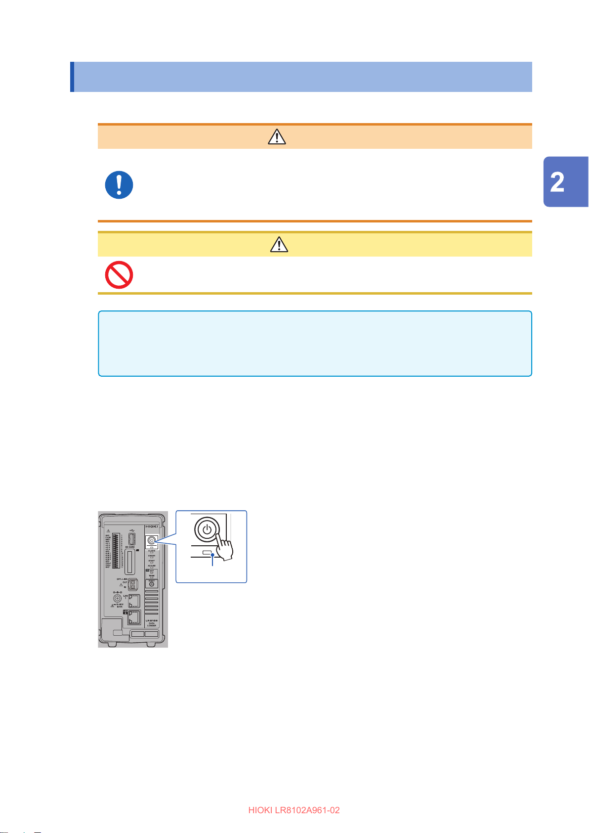
Turning ON and OFF the Power
HIOKI LR8102A961-02
2.7 Turning ON and OFF the Power
For M1100, also use the POWER key for LR8101 and LR8102 to turn ON/OFF the power.
WARNING
Before turning ON the power, make sure that the supply voltage you
plan to use falls within the specied supply voltage range.
Supplying a voltage that falls outside the specied range could damage the
instrument, causing bodily injury.
CAUTION
Do not input voltage to the input terminal while the instrument is powered OFF.
Doing so could damage the instrument.
Connection (Preparation for Measurements)
IMPORTANT
• Be sure to turn OFF the power after using the instrument.
• An instantaneous power failure longer than 40 ms could shut down the power supply, causing
the instrument to malfunction. Check the status of the power supply.
Procedure to turn on the instrument
Pressing the POWER key turns ON the instrument. The POWER LED lights up in green.
Procedure to turn o the instrument
When the POWER key is pressed, the LEDs blink for 5 seconds.
Pressing the POWER key again while the LEDs are blinking turns OFF the power.
The POWER LED is turned OFF.
POWER LED
71
Page 72
SD Memory Card and USB Drive
HIOKI LR8102A961-02
2.8 SD Memory Card and USB Drive
The measurement data and the setting conditions of the instrument can be stored in SD memory
cards and USB drives.
In addition, the stored data can be loaded and reproduced on the instrument.
For the data storage, use the following options.
Z4001 SD Memory Card (2 GB), Z4003 SD Memory Card (8 GB),
Z4006 USB Drive (16 GB)
WARNING
Do not modify, disassemble, or repair an SD memory card and USB
drive.
Doing so could result in serious bodily injury or re.
Keep these parts out of reach of children.
Children may accidentally swallow an SD memory card or USB drive.
CAUTION
Do not attach a label and the like to an SD memory card.
Doing so could cause the SD memory card to overheat, exposing the operator to a
risk of being burned or causing re.
Do not allow water to drip on the terminal of an SD memory card or USB drive.
Do not touch the terminal or contact surface of an SD memory card. Do not
allow a metal object to contact these areas.
Do not bend or drop an SD memory card. Do not subject an SD memory card to
mechanical shock.
While the instrument is accessing an SD memory card or USB drive, do not
subject the instrument to vibration or mechanical shock. Do not turn OFF
the instrument. Do not remove an SD memory card or USB drive from the
instrument.
Before formatting an SD memory card, make sure that no necessary
information, such as les, is stored on the card.
The internal data could be damaged or lost.
72
Do not forcefully insert an SD memory card or USB drive with the wrong side
up or in the wrong direction.
The SD memory card, the USB drive, or the instrument can be damaged.
Do not transport the instrument while it is connected to a USB drive.
The USB drive or the instrument can be damaged.
Page 73
SD Memory Card and USB Drive
HIOKI LR8102A961-02
CAUTION
Take measures to prevent static electricity from being applied to an SD memory
card or USB drive.
Failure to do so could damage the SD memory card or USB drive and cause the
instrument to malfunction.
Use a USB drive within the specied ranges of temperature and humidity.
The USB drive can be damaged.
Back up important data and store it in a safe place.
SD memory cards and USB drives have a service life because ash memory is used.
They lose the ability to store and load data after extended or frequent use. If you
encounter this issue, purchase a new drive. Hioki is not liable for data stored on SD
memory cards or USB drives, regardless of the nature or cause of the accident or
damage involved.
When formatting an SD memory card or USB drive with a PC, select the
FAT/FAT32.
The media formatted to other formats (NTFS, etc.) cannot be recognized with the
instrument.
Connection (Preparation for Measurements)
Discharge static electricity from your body before handling an SD memory card
or USB drive.
Turn ON the instrument before inserting an SD memory card or USB drive.
Failure to do so could damage the SD memory card or USB drive, or cause the
instrument to malfunction. The instrument may fail to start up if it is turned on while a
USB drive is inserted.
IMPORTANT
• The operation is guaranteed only for the optional SD memory cards and USB drives. The
operation of storage media other than the options is not guaranteed.
• Use the instrument to format a new SD memory card or USB drive. If the media are formatted
with a PC, the realtime saving may not be completed in time.
• Check that the write protect (write inhibit) of the SD memory card is disabled.
• Follow the procedure below to remove an SD memory card and USB drive from the instrument.
73
Page 74
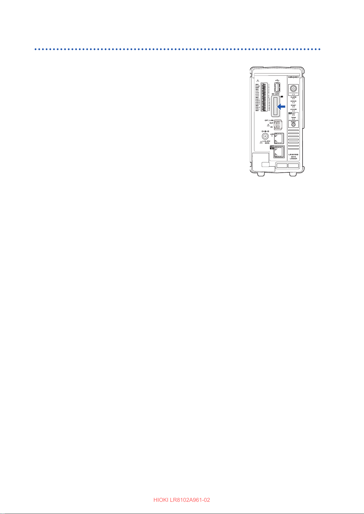
SD Memory Card and USB Drive
HIOKI LR8102A961-02
Installing and removing an SD memory card
Installing an SD memory card
Turn an SD memory card with the surface marked with “▲”
1
facing left, and insert the card into the SD card slot.
Insert the SD memory card until the card is locked with a
2
click.
Removing the SD memory card
Make sure that the instrument is not accessing (saving,
1
loading, etc.) the SD memory card.
Conrm that the ACCESS LED is turned OFF.
Press and release the SD memory card. When the card is
2
partially pushed out, pinch the card and pull it out.
74
Page 75
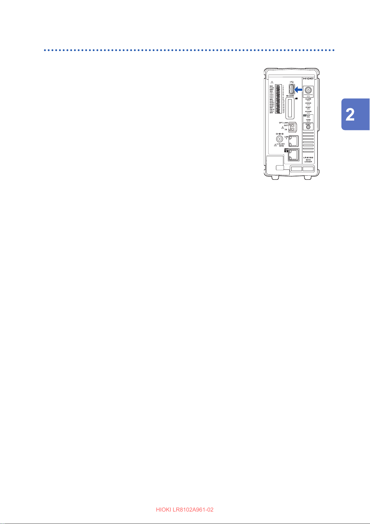
Installing and removing a USB drive
HIOKI LR8102A961-02
Installing a USB drive
Check the connection between the USB drive and the USB
1
connector.
Insert the USB drive completely.
2
SD Memory Card and USB Drive
Removing the USB drive
Make sure that the instrument is not accessing (saving,
1
loading, etc.) the USB drive.
Conrm that the ACCESS LED is turned OFF.
Pull out the USB drive.
2
Connection (Preparation for Measurements)
75
Page 76
Wiring the Power Measurement Module to the Measurement Line
HIOKI LR8102A961-02
2.9 Wiring the Power Measurement Module to the Measurement Line
Setting the wiring mode and current sensor
Set the wiring mode according to the measurement line.
When combining multiple channels for measurements (as in measuring a multi-phase system),
connect the same current sensor to all the channels involved.
Wiring setting is only available for those channels in the same module.
Select the wiring mode for each module.
When measuring the DC line, also select this wiring.
1P2W
(Single-phase 2-wire)
Measurement can be performed on both the source and ground connection sides
of the current sensor.
The connection diagram shows both of these two patterns.
Reference: “Connection diagram” (p. 83)
1P3W (Single-phase
3-wire)
3P3W2M
(3-phase 3-wire)
3V3A (3-phase 3-wire)
3P3W3M
(3-phase 3-wire)
3P4W
(3-phase 4-wire)
Settings
Syntax Command
Example
Query
Syntax Query
Example
Parameter
A$
= TYPE1,TYPE2,TYPE3,TYPE4,TYPE5,TYPE6
TYPE1
TYPE2 1P3W+1P2W
TYPE3 3P3W2M+1P2W
TYPE4 3V3A
TYPE5 3P3W3M
TYPE6 3P4W
Power channel settings included in measurement line combinations
• The TYPE2 and TYPE3 settings congured for CH1 are applied to CH2.
• The TYPE4, TYPE5, and TYPE6 settings congured for CH1 are applied to CH2 and CH3.
1P2W
−
This method uses two channels of the three-phase delta connection line to measure
power using the two-wattmeter method. It accurately measures the active power of
unbalanced and distorted waveforms.
The apparent, reactive power, and power factor values of an unbalanced line may vary
compared to other measuring instruments. In such a case, use 3V3A or 3P3W3M.
This method uses three channels of the three-phase delta connection line for
measurement with the two-wattmeter method. It is preferred when compatibility
with Hioki’s conventional power meters like the 3193 model is important.
It correctly measures not only the active power but also the apparent and reactive
power, and power factor, even on unbalanced lines.
This method uses three channels of the three-phase delta connection line to
measure power using the three-wattmeter method. This method is suitable for
measuring motor power in PWM inverter assessments, where high-frequency
component leakage currents are signicant. It ensures accuracy even when using
the 3V3A method, which might otherwise introduce errors.
This method involves using three channels of the three-phase Y (star) connection
line to measure using the three-wattmeter method.
:POWer:MODule[n:1 to 4]:WIRing A$
:POWer:MODule1:WIRing TYPE5
:POWer:MODule[n:1 to 4]:WIRing?
Response
:POWer:MODule1:WIRing?
(Response)
3
×
A$
:POWER:MODULE1:WIRING TYPE5 (When the header is ON)
76
Page 77
Wiring the Power Measurement Module to the Measurement Line
HIOKI LR8102A961-02
Current sensor automatic detection function
The M7103 Power Measurement Module automatically acquires the rated current and phase
compensation value of the connected current sensor.
It drastically reduces the time required for pre-measurement settings, and also enables power
measurement based on the accurate sensor information.
(Current sensor with memory only)
M7103 only detects the rated current of the connected current sensor in the following cases.
• When a current sensor without memory is connected to M7103
• When M7103 cannot read the phase compensation value, etc., of the current sensor
• When the current sensor is connected using the CT9920 conversion cable
Optional current sensors
Reference: “Current measurement options” (p. 374)
Acquire the sensor type, rating, and serial No.
1
Query
Syntax Query
Response <Sensor type>, <Sensor rating>, Sensor serial No.>
Example :POWer:MODule1:SENSor1:ID?
(Response)
Parameter
<Sensor type> = Sensor model, Probe1, Probe2
Sensor
model
Probe1 ME15W connector: Current sensor without memory
Probe2 PL14 connector: When the PL14 connector’s current sensor is connected with the CT9920
ME15W connector: Current sensor with memory
conversion cable
:POWer:MODule[n:1 to 4]:SENSor[ch:1~3]:ID?
:POWER:MODULE1:SENSOR1:ID CT6872,50A_ACDC,123456789
(When the header is ON)
:POWER:MODULE1:SENSOR1:ID Probe1,50A_ACDC,-
(When the header is ON)
:POWER:MODULE1:SENSOR1:ID Probe2,1mV/A,-
(When the header is ON)
Connection (Preparation for Measurements)
<Sensor rating>
Sensor model,
For Probe 1
For Probe 2 Current output rate (0.1 mV/A, 1 mV/A, 10 mV/A, 100 mV/A, 1 V/A)
<Sensor serial No.> = 9-digit NR1 numerical value
Note
If the serial No. cannot be acquired for the sensor, a hyphen (−) is returned.
If the Probe1 sensor is not connected, the sensor rating will be “50A ACDC”.
When Probe 2 is selected, the specied output rate is acquired, regardless of the sensor connection status.
The current sensor is automatically detected when the power is turned ON and measurement starts.
If the current sensor should be detected manually, execute “
(AC sensor)
1A_AC, 2A_AC, 5A_AC, 10A_AC, 20A_AC, 50A_AC,100A_AC, 200A_AC,
500A_AC, 1kA_AC, 2kA_AC, 5kA_AC,
(ACDC sensor)
1A_ACDC, 2A_ACDC, 5A_ACDC, 10A_ACDC, 20A_ACDC,50A_ACDC,
100A_ACDC, 200A_ACDC, 500A_ACDC, 1kA_ACDC, 2kA_ACDC, 5kA_ACDC
:POWer:SENSor:CHECk
”.
77
Page 78
Wiring the Power Measurement Module to the Measurement Line
HIOKI LR8102A961-02
Acquire the sensor adjustment date.
2
Query
Syntax Query
Response
Example
Parameter
YYYY<NR1>
MM<NR1>
DD<NR1>
Note
The current sensor is automatically detected when the power is turned ON and measurement starts.
If the current sensor should be detected manually, execute “
Acquire the sensor calibration date.
3
Query
Syntax Query
Example
Parameter
YYYY<NR1>
MM<NR1>
DD<NR1>
Note
The current sensor is automatically detected when the power is turned ON and measurement starts.
If the current sensor should be detected manually, execute “
Year 2021 to 2037
Month 1 to 12
Day 1 to 31
Year 2021 to 2037
Month 1 to 12
Day 1 to 31
:POWer:MODule1:SENSor1:ADATE?
(Response)
ON)
Response
:POWer:MODule1:SENSor1:CDATE?
(Response)
ON)
:POWer:MODule[n:1 to 4]:SENSor[ch:1 to 3]:ADATE?
YYYY,MM,DD
:POWER:MODULE1:CURRENT1:ADATE 2024,6,28
:POWer:MODule[n:1~4]:SENSor[ch:1~3]:CDATE?
YYYY,MM,DD
:POWER:MODULE1:CURRENT1:CDATE 2024,6,28
:POWer:SENSor:CHECk
:POWer:SENSor:CHECk
(When the header is
”.
(When the header is
”.
Current sensor detection
This command detects the types of current sensors connected to the M7103 Power Measurement
Module.
Use it when you wish to detect current sensors manually. Current sensors are detected
automatically when the instrument is powered on and at the start of measurement.
Settings
Syntax Command
Example
:POWer:SENSor:CHECk
:POWer:MODule1:SENSor1:ID?
:POWer:MODule1:SENSor2:ID?
:POWer:MODule1:SENSor3:ID?
:POWer:SENSor:CHECk
78
Page 79
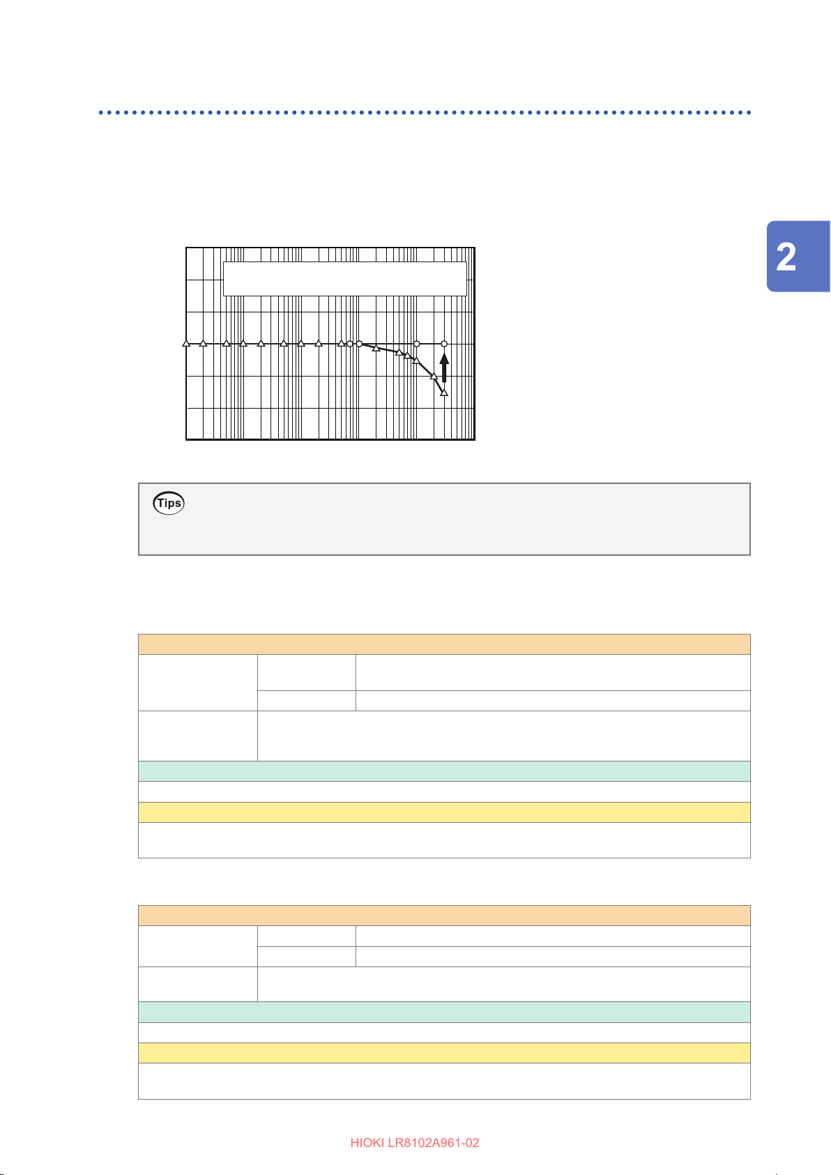
Wiring the Power Measurement Module to the Measurement Line
HIOKI LR8102A961-02
Current sensor phase compensation
In general, current sensor phase errors are more likely to increase gradually in the high-frequency
area within the frequency band. It is possible to reduce power measurement errors in the highfrequency domain by correcting the measurement values using the phase characteristics
information specic to the sensor.
Image view
30
○
20
10
)
°
0
Phase (
10
−
20
−
30
−
: Phase characteristics after compensation
△
: Phase characteristics before compensation
100 1 k 10 k 100 k
Frequency (Hz)
1 M10
Connection (Preparation for Measurements)
Phase compensation of current sensor with memory
When the current sensor with memory is used, the phase of the current sensor is automatically
corrected.
How to check the phase compensation value
Acquiring the current sensor phase compensation frequency
Query
Syntax Query
Response
Example
:POWer:MODule1:CURRent1:FREQuency?
(Response) :
Parameter
A
= 0.1 and above
Note
The current sensor is automatically detected when the power is turned ON and measurement starts.
If the current sensor should be detected manually, execute “
Acquiring the phase dierence for current sensor phase compensation
:POWer:MODule[n:1 to 4]:CURRent[ch:1 to
3]:FREQuency?
A<NR2>
POWER:MODULE1:CURRENT1:FREQUENCY 100000
(When the header is ON)
:POWer:SENSor:CHECk
”.
Query
Syntax Query
Response
Example
:POWer:MODule1:CURRent1:DEGRee?
(Response)
:POWer:MODule[n:1 to 4]:CURRent[ch:1 to 3]:DEGRee?
A<NR2>
:POWER:MODULE1:CURRENT1:DEGREE -1.41
(When the header is ON)
Parameter
A
= −180.0 to 180.0
Note
The current sensor is automatically detected when the power is turned ON and measurement starts.
If the current sensor should be detected manually, execute “
:POWer:SENSor:CHECk
”.
79
Page 80
Wiring the Power Measurement Module to the Measurement Line
HIOKI LR8102A961-02
Setting the output rate
Settings
Syntax Command
Example
Query
Syntax Query
Example
Parameter
A$ = 0.1mV/A, 1mV/A, 10mV/A, 100mV/A, 1V/A
0.1mV/A
1mV/A
10mV/A
100mV/A
1V/A
Note
Changing the settings will also aect the settings of other channels included in the measurement line
combination.
400 A, 800 A, 2 kA, 4 kA, 8 kA, 20 kA range conguration
40 A, 80 A, 200 A, 400 A, 800 A, 2 kA range conguration
4 A, 8 A, 20 A, 40 A, 80 , 200 A range conguration
0.4 A, 0.8 A, 2 A, 4 A, 8 A, 20 A range conguration
0.04 A, 0.08 A, 0.2 A, 0.4 A, 0.8 A, 2 A range conguration
:POWer:MODule1:CURRent1:RATE 1mV/A
Response
:POWer:MODule1:CURRent1:RATE?
(Response)
:POWer:MODule[n:1 to 4]:CURRent[ch:1 to 3]:RATE A$
:POWer:MODule[n:1 to 4]:CURRent[ch:1 to 3]:RATE?
A$
:POWER:MODULE1:CURRENT1:RATE 1mV/A
(When the header is ON)
80
Page 81
Wiring the Power Measurement Module to the Measurement Line
HIOKI LR8102A961-02
Zero adjustment and degaussing (DMAG)
Before wiring, execute zero adjustment while no voltage and current are input. Zero adjustment is
executed for all ranges of all input channels simultaneously. Also, when the current sensor available
for AC/DC measurement is connected to the M7103 Power Measurement Module, degaussing
(DMAG) of the current sensor is also executed at the same time.
When the power is ON, allow at least 30 minutes for the instrument to warm up.
1
Connect the current sensor and voltage cords to M7103.
2
When the current measurement value is corrected, the current sensor should be included.
When the current sensor connected to the instrument is available for zero adjustment,
3
perform zero adjustment on the current sensor side.
There are some current sensor models that allow you to perform zero adjustment using a knob.
Set the wiring mode and current sensor.
4
Execute zero adjustment.
5
Settings
Syntax Command
Example
Query
Syntax Query
Example
Parameter
A$
= NONE, BUSY, OK, ERROR
:POWer:DEMAg
Response
:POWer:DEMAg?
(Response)
:POWer:DEMAg
:POWer:DEMAg?
A$
:POWER:DEMAG OK
(When the header is ON)
Connection (Preparation for Measurements)
NONE
BUSY
OK
ERROR
It takes approximately 15 seconds to complete the execution of zero adjustment.
Once the “OK” or “ERROR” response for [:POWer:DEMAg?] is returned, send the next command.
When the beep sound is enabled, a beep sound is issued once in the case of a success, or it is
issued twice in the case of a failure.
Reference: “Beep sound” (p. 289)
Perform wiring to the measurement line.
6
After startup before execution of zero adjustment
Zero adjustment is being executed
Normal end
Zero adjustment failed
81
Page 82
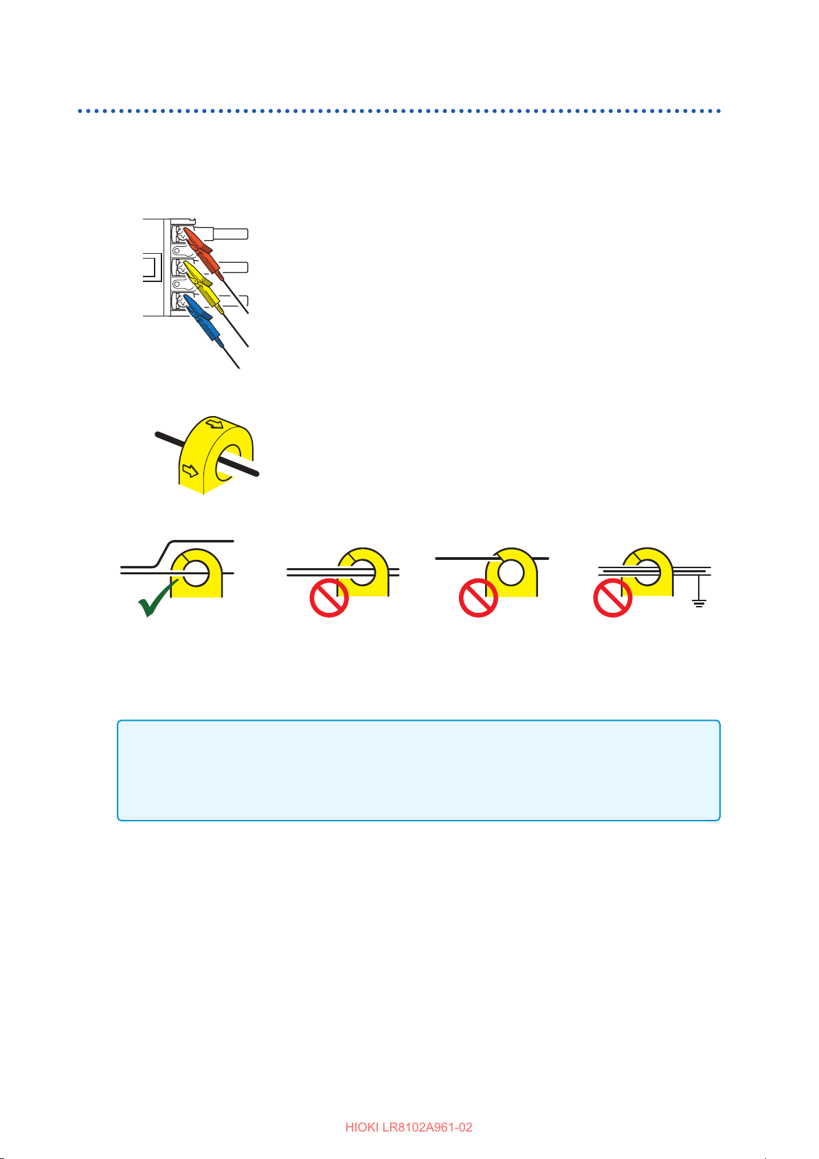
Wiring the Power Measurement Module to the Measurement Line
HIOKI LR8102A961-02
Wiring to the measurement line
After executing zero adjustment, connect the voltage cords and current sensor to the measurement
line according to the connection diagram.
To ensure correct measurement, perform wiring as indicated in the connection diagram (p. 83).
Voltage cords
Securely clip the voltage cords to the relevant metal part, such as the screw
and wiring bar on the power supply side.
Current sensor
Source
Clamp the current sensor onto the wire with the current direction arrow
pointing towards the load side.
Load
OK
IMPORTANT
• In the connection diagram, the phase names are indicated as “A, B, C”. When wiring, use the
appropriate labels such as “R, S, T” or “U, V, W”, etc., according to the designated names.
• Clamp the sensor around only one conductor. The current cannot be measured if the clamp
encompasses two or more wires together, whether in a single-phase or three-phase setup.
NO
No clamping on 2 or more lines No pinching of line No clamping on
NONO
shielded line
82
Page 83
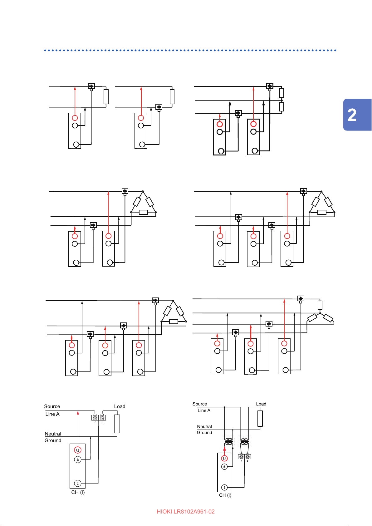
Connection diagram
CH 2 CH 1
HIOKI LR8102A961-02
Wiring the Power Measurement Module to the Measurement Line
Single-phase 2-wire (1P2W)
Source
Line A
Neutral
Ground
U
I
CH (i)
Load
Source
Neutral
Ground
3-phase 3-wire (3P3W2M)
Source
Line A
Line B
Line C
U
U
±
I
CH 2 CH 1
±
I
Line A
U
±±
I
CH (i)
(i): Measurement power
channel
Load
Load
Single-phase 3-wire (1P3W)
Source
Line A
Neutral
Line B
U
±
I
3-phase 3-wire (3V3A)
Source
Line A
Line B
Line C
U
±
I
Load
U
±
I
Connection (Preparation for Measurements)
Load
U
±
I
CH 2 CH 1CH 3
U
±
I
3-phase 3-wire (3P3W3M)
Source
Line A
Line B
Line C
U
±
I
U
±
I
CH 2 CH 1CH 3
U
±
I
Load
Normal connections when using the PW9100A
PW9100A
3-phase 4-wire (3P4W)
Source
Line A
Neutral
Line B
Line C
U
±
I
CH3
U
±
I
CH2
U
±
I
CH1
Load
When using the PW9100A with a PT and CT
PW9100A
83
Page 84
Wiring the Power Measurement Module to the Measurement Line
HIOKI LR8102A961-02
Checking connection
Check the measured values to conrm that the voltage cords and current sensor are connected
appropriately.
In the 3P3W2M and 3V3A congurations, the measured active power P for each channel may
sometimes be negative.
Situation Cause
The measured voltage value is
too high.
The measured voltage value is
too low.
The measured current value is
not valid.
The active power measurement
value is a negative value.
• The voltage cords are not securely inserted into the voltage input
terminal on the instrument.
• The voltage cords are not connected properly.
• The current sensor is not securely inserted into the current input
terminal on the instrument.
• The current sensor is not connected properly.
• The voltage cords are not connected properly.
• When wiring, the arrow that indicates the current ow direction of
the current sensor does not point to the load side.
Reference: “Wiring to the measurement line” (p. 82)
84
Page 85
Setting and Connecting the LAN
HIOKI LR8102A961-02
2.10 Setting and Connecting the LAN
The instrument and a PC can be connected using a LAN cable.
You can perform the following with LAN1
• Record and observe the settings of the instrument and the measurement data with Logger Utility.
(p. 311)
• Remotely operate the instrument (setting, data acquisition, screen monitoring, etc.) using a
standard browser, such as Microsoft Edge (HTTP server). (p. 313)
• Download les from the media (SD memory card and USB drive) to the PC (FTP server). (p. 324)
• Automatically send waveform data saved in the media of the instrument to the network or the FTP
server of the remote PC (FTP client). (p. 326)
• Control the instrument using communication commands. (p. 101)
• Control the instrument using XCP on Ethernet (TCP). (p. 339)
You can perform the following with LAN2 (LR8102 only)
• Output the measurement data based on the UDP. (p. 347)
• Control the instrument using XCP on Ethernet (UDP). (p. 339)
Connection (Preparation for Measurements)
IMPORTANT
Be sure to congure the LAN settings before connecting the instrument to the network. If you
change the settings while the instrument is connected to a network, the instrument may have the
same IP address as another device on the LAN, causing incorrect address information to be sent
to the LAN.
85
Page 86
Setting and Connecting the LAN
HIOKI LR8102A961-02
Checking before connection
The settings are dierent when connecting the instrument to an existing network and when
connecting one instrument to one PC.
When connecting the instrument to an existing network
You must rst have the network system administrator (department) allocate the following
parameters. Ensure that the instrument uses a unique IP address that is not being used by any
other device on the network.
DHCP server DHCP server: Used/not used
Host name
IP address
Subnet mask
Port LAN1
Host name
IP address
Subnet mask: ___.___.___.___
(IP address and subnet mask are not required when using DHCP server)
TCP/IP port number to be used: ___X (default 880x)
Specify at least the rst 3 digits of the 4 or 5 digits. The last digit is used and
reserved for the instrument
(The last digit: 0 for Logger Utility, 2 for the communication commands, 5 for
XCP on Ethernet)
Specify when the default setting (8800 to 8809) is not available
Example of port number (with 880x default setting)
Communication command: 8802 (Use this port for command control)
Logger Utility: 8800
XCP on Ethernet: 8805
LAN2
UDP/IP port number to be used: ___X (default 880X)
Specify at least the rst 3 digits of the 4 or 5 digits. The last digit is used and
reserved for the instrument
(The last digit: 1 for the measurement data output, 5 for XCP on Ethernet)
Specify when the default setting (8800 to 8809) is not available
Example of port number (with 880x default setting)
Measurement data output: 8801
XCP on Ethernet: 8805
Gateway Gateway: Used/not used
IP address (when used): ___.___.___.___
(Setting is not required when using DHCP server, because the address is
obtained from the server.)
DNS DNS: used/not used
IP address (when used): ___.___.___.___
(Setting is not required when using DHCP server, because the address is
obtained from the server.)
86
Page 87
Setting and Connecting the LAN
HIOKI LR8102A961-02
When connecting one instrument and one PC (local network without external connection)
The following address is recommended if there is no administrator or the setting is discretionary.
Setting example
DHCP server OFF
Host name Discretionary setting (must be a unique name)
IP address PC 192.168.1.1
Logger 1 192.168.1.2
Logger 2 192.168.1.3 (numbered consecutively)
Subnet mask 255.255.255.0
Port 880X
Gateway OFF
DNS OFF
Parameter
DHCP server (Dynamic
Host Conguration
Protocol) is used
Host name This name represents the instrument on the network. Ensure that the
IP address The IP address is used to identify individual devices that are connected to the
↓ ↓
Connection (Preparation for Measurements)
DHCP is a method by which devices can automatically acquire and congure
themselves with an IP address and other information.
When the DHCP server is enabled and the server is operating on the same
network as the instrument, the instrument can automatically acquire and
congure the IP address, subnet mask, and gateway.
instrument uses a unique name that is not being used by any other device on
the network.
Since the instrument does not support dynamic DNS, the host name setting is
not registered in the DNS.
network.
Ensure that the instrument uses a unique name that is not being used by any
other device on the network. If the DHCP server is enabled, the setting will be
congured automatically using the server.
Subnet mask The subnet mask is used to separate the IP address into the portion that
indicates the network and the portion that indicates the device.
Ensure that the instrument uses the same subnet mask that is being used by
other devices on the same network. If the DHCP server is enabled, the setting
will be congured automatically using the server.
Gateway
IP address
DNS
(Domain Name System)
• When connecting the instrument to a network
When the PC to be used (communicating device) is on a dierent network
than the network with which the instrument is connected, set this parameter
to [ON] and specify the device that serves as the gateway.
When the PC is on the same network, generally use the same setting as the
default gateway setting of the PC.
• When connecting one instrument and one PC
Set this parameter to [OFF] when they are connected to the same hub.
If the DHCP server is enabled, the setting will be obtained from the server.
If the DNS is enabled, the communication partner can be specied with its
name instead of the IP address. (The IP addresses are dicult to remember
because they are a series of numbers. It is easier if devices can be specied
with their names instead of the IP addresses.)
If a server that allows you to obtain the IP addresses using the names is
operating on the network, the IP address of the communication partner can
be looked up from the name by querying the server. If the DHCP server is
enabled, the setting will be obtained from the server.
87
Page 88
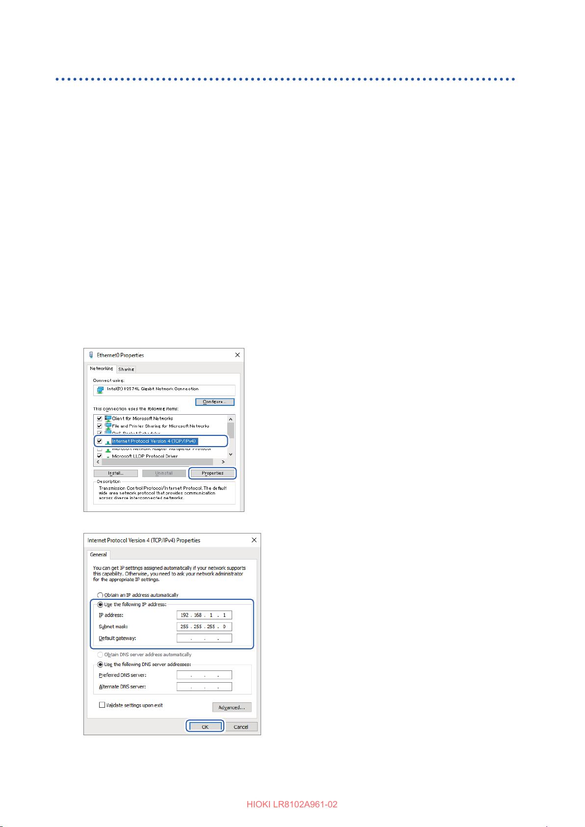
Setting and Connecting the LAN
HIOKI LR8102A961-02
Network settings on PC
The setting method is the same for the case when connecting one instrument and one PC and the
case when connecting one PC and multiple instruments via a hub.
The following network is assumed here.
• IP address: 192.168.1.0/24 (network address)
or 192.168.1.1 (private IP address*1)
• Subnet mask: 255.255.255.0
*1. You may set the IP address as desired. However, a private IP address is recommended.
For Windows 10 or Windows 11
Display the network connections from
1
[Control Panel] > [Network and Sharing
Center] > [Change adapter settings].
Right-click the icon of the adapter to be
2
used for communications (named [Local
Area Connection], [Ethernet], etc.), and then
select [Properties].
Select [Internet Protocol Version 4 (TCP/
3
IPv4)], and then click [Properties].
Enter [IP address] and [Subnet mask], then
4
click [OK].
88
Page 89
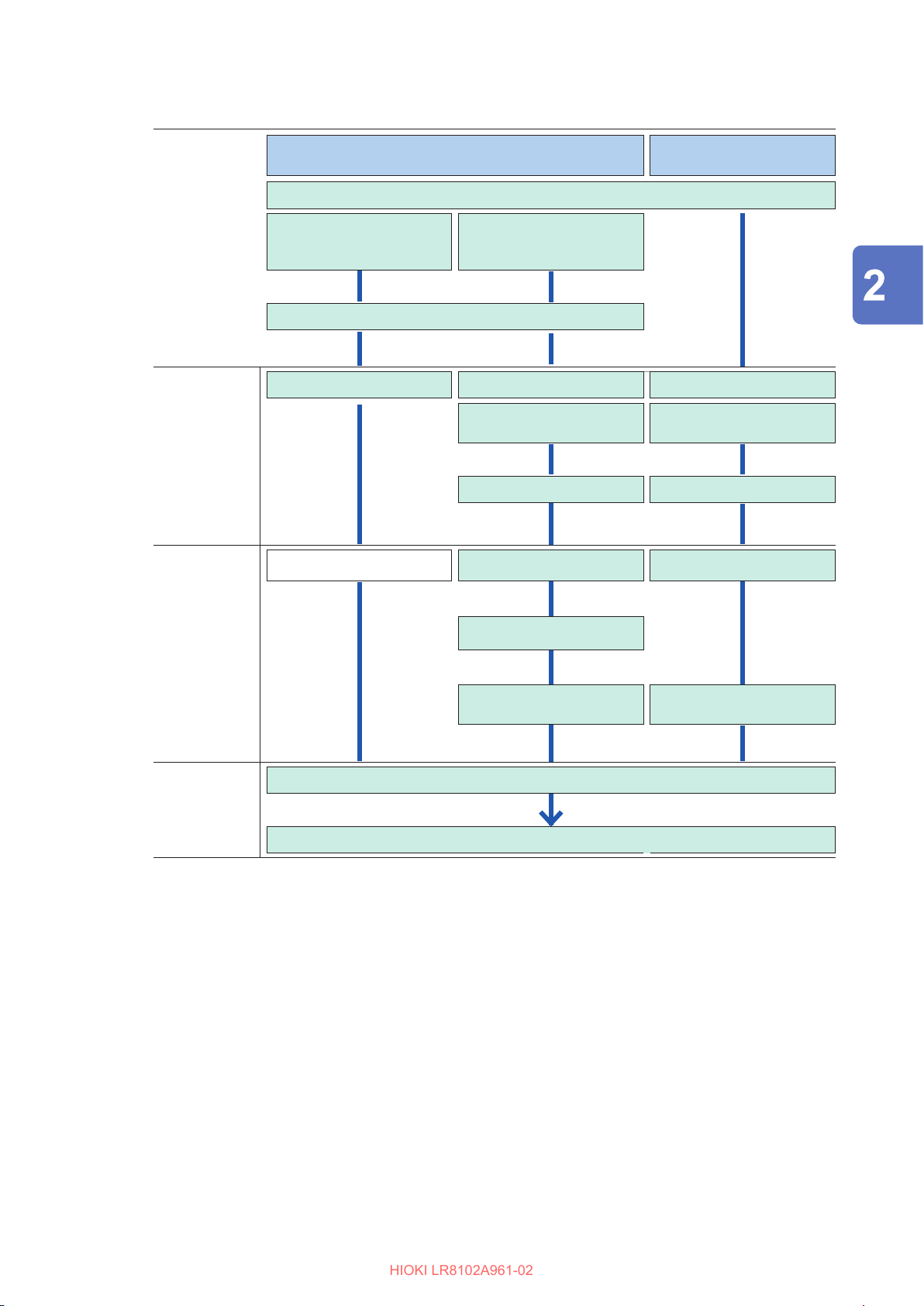
Workow for LAN settings
HIOKI LR8102A961-02
Setting and Connecting the LAN
Intended use Use the instrument connected to an existing network
Input the host name.
Obtain the IP address
automatically and connect
to the network
(To allocate a name to the instrument) [Host name]
[DHCP server]: [ON] [DHCP server]: [OFF] [DHCP server]: [OFF]
Settings within
the same
network
(Automatically set) [Gateway]: [ON] [Gateway]: [OFF]
Use the prescribed IP
address to connect to the
network
[IP address] of this
instrument
[Subnet mask] [Subnet mask]
Use one instrument and
one PC
Connection (Preparation for Measurements)
[IP address] of this
instrument
Settings for
connecting
to another
network as
well (using a
gateway)
Connection
*1. LAN1 only
[Gateway IP]
[DNS]: [ON]
[DNS IP]*
Update the settings
Connect a LAN cable
1
[DNS]: [OFF]*
1
89
Page 90
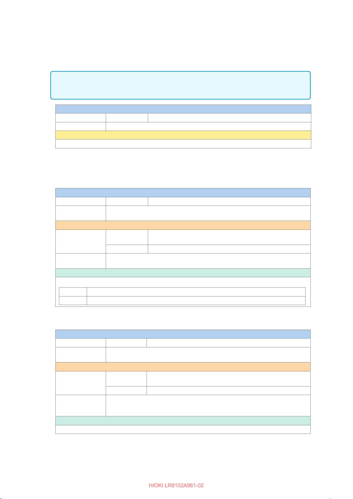
Setting and Connecting the LAN
HIOKI LR8102A961-02
Conguring the settings for LAN1
Congure the following settings to perform the LAN communications. (p. 101)
Update the LAN1 settings.
IMPORTANT
The LAN1 settings will not be updated until this command is executed.
Execute the command after completing the LAN1 settings.
Settings
Syntax Command
Example
Note
The ongoing LAN communications are disconnected.
:SYSTem:COMMunicate:LAN:UPDate
DHCP server
When the DHCP server is set to ON, the IP address and the subnet mask can be obtained automatically.
PREParation?
For
, the setting made before the update of the LAN1 settings is returned.
:SYSTem:COMMunicate:LAN:UPDate
Settings
Syntax Command
Example
Query
Syntax Query
Example
Parameter
A$ =
OFF,ON
OFF
ON
Disables the DHCP function.
Enables the DHCP function.
:SYSTem:COMMunicate:LAN:DHCP ON
:SYSTem:COMMunicate:LAN:UPDate
Response
:SYSTem:COMMunicate:LAN:DHCP?
(Response)
Host name
PREParation?
For
Settings
Syntax Command
Example
Query
Syntax Query
Example
Parameter
A$ =
Character string of host name (up to 12 single-byte characters)
, the setting made before the update of the LAN1 settings is returned.
:SYSTem:COMMunicate:LAN:HOSTname "LOGGER"
:SYSTem:COMMunicate:LAN:UPDate
Response
:SYSTem:COMMunicate:LAN:HOSTname?
(Response)
:SYSTem:COMMunicate:LAN:DHCP A$
:SYSTem:COMMunicate:LAN:DHCP?
:SYSTem:COMMunicate:LAN:DHCP:PREParation?
A$
:SYSTEM:COMMUNICATE:LAN:DHCP ON
:SYSTem:COMMunicate:LAN:HOSTname "A$"
:SYSTem:COMMunicate:LAN:HOSTname?
:SYSTem:COMMunicate:LAN:HOSTname:PREParation?
"A$"
:SYSTEM:COMMUNICATE:LAN:HOSTNAME "LOGGER"
(When the header is ON)
(When the header is ON)
90
Page 91
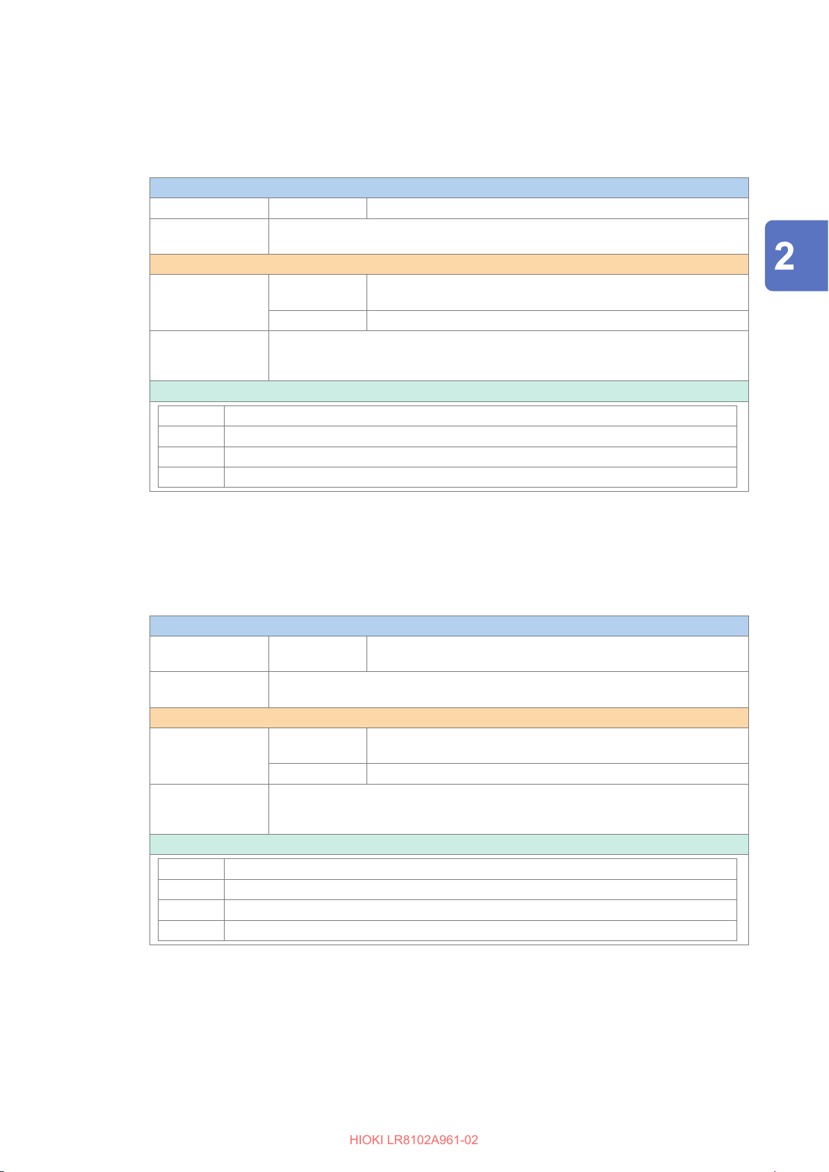
Setting and Connecting the LAN
HIOKI LR8102A961-02
IP address
The IP address is used to identify individual devices that are connected to the network. Ensure that the
instrument uses a unique name that is not being used by any other device on the network. If the DHCP server
is enabled, the setting will be congured automatically using the server.
PREParation?
For,
Settings
Syntax Command
Example
Query
Syntax Query
Example
Parameter
, the setting made before the update of the LAN1 settings is returned.
:SYSTem:COMMunicate:LAN:IPADdress ip1,ip2,ip3,ip4
:SYSTem:COMMunicate:LAN:IPADdress 192,168,1,100
:SYSTem:COMMunicate:LAN:UPDate
:SYSTem:COMMunicate:LAN:IPADdress?
:SYSTem:COMMunicate:LAN:IPADdress:PREParation?
Response
:SYSTem:COMMunicate:LAN:IPADdress?
(Response)
ip1<NR1>,ip2<NR1>,ip3<NR1>,ip4<NR1>
:SYSTEM:COMMUNICATE:LAN:IPADDRESS 192,168,1,100
(When the header is ON)
Connection (Preparation for Measurements)
ip1
ip2
ip3
ip4
0 to 255
0 to 255
0 to 255
0 to 255
Subnet mask
The subnet mask is used to separate the IP address into the portion that indicates the network and the portion
that indicates the device.
Ensure that the instrument uses the same subnet mask that is being used by other devices on the same
network. If the DHCP server is enabled, the setting will be congured automatically using the server.
PREParation?
Settings
Syntax Command
Example
Query
Syntax Query
Example
Parameter
, the setting made before the update of the LAN1 settings is returned.
:SYSTem:COMMunicate:LAN:SMASk
mask1,mask2,mask3,mask4
:SYSTem:COMMunicate:LAN:SMASk 255,255,255,0
:SYSTem:COMMunicate:LAN:UPDate
:SYSTem:COMMunicate:LAN:SMASk?
:SYSTem:COMMunicate:LAN:SMASk:PREParation?
Response
:SYSTem:COMMunicate:LAN:SMASk?
(Response)
mask1<NR1>mask2<NR1>,mask3<NR1>,mask4<NR1>
:SYSTEM:COMMUNICATE:LAN:SMASK 255,255,255,0
(When the header is ON)
mask1
mask2
mask3
mask4
0 to 255
0 to 255
0 to 255
0 to 255
91
Page 92
Setting and Connecting the LAN
HIOKI LR8102A961-02
Port
The last digit is used by the LAN1 system.
Example: No matter which number between 8800 and 8809 is specied, 8802 is the communication command
port.
(The last digit: 0 for Logger Utility, 2 for the communication commands, 5 for XCP on Ethernet)
PREParation?
For
Settings
Syntax Command
Example
Query
Syntax Query
Example
Parameter
no =
1020 to 65520
Note
For example, if a number between 8800 and 8809 is specied, the setting will always return 8800.
, the setting made before the update of the LAN1 settings is returned.
:SYSTem:COMMunicate:LAN:CONTrol no
:SYSTem:COMMunicate:LAN:CONTrol 8800
:SYSTem:COMMunicate:LAN:UPDate
:SYSTem:COMMunicate:LAN:CONTrol?
:SYSTem:COMMunicate:LAN:CONTrol:PREParation?
Response
:SYSTem:COMMunicate:LAN:CONTrol?
(Response)
no
:SYSTEM:COMMUNICATE:LAN:CONTROL 8800
(When the header is ON)
Gateway IP
If the DHCP server is set to ON, the setting will be congured automatically.
Setting 0,0,0,0 disables the use of the Gateway.
PREParation?
For
Settings
Syntax Command
Example
Query
Syntax Query
Example
Parameter
ip1
ip2
ip3
ip4
, the setting made before the update of the LAN1 settings is returned.
:SYSTem:COMMunicate:LAN:GATeway ip1,ip2,ip3,ip4
:SYSTem:COMMunicate:LAN:GATeway 192,168,1,100
:SYSTem:COMMunicate:LAN:UPDate
:SYSTem:COMMunicate:LAN:GATeway?
:SYSTem:COMMunicate:LAN:GATeway:PREParation?
Response
:SYSTem:COMMunicate:LAN:GATeway?
(Response)
0 to 255
0 to 255
0 to 255
0 to 255
ip1<NR1>,ip2<NR1>,ip3<NR1>,ip4<NR1>
:SYSTEM:COMMUNICATE:LAN:GATEWAY 192,168,1,100
(When the header is ON)
92
Page 93
DNS
HIOKI LR8102A961-02
Setting 0,0,0,0 disables the use of the DNS.
PREParation?
For
Settings
Syntax Command
Example
Query
Syntax Query
Example
Parameter
, the setting made before the update of the LAN1 settings is returned.
:SYSTem:COMMunicate:LAN:DNS ip1,ip2,ip3,ip4
:SYSTem:COMMunicate:LAN:DNS 192,168,1,100
:SYSTem:COMMunicate:LAN:UPDate
:SYSTem:COMMunicate:LAN:DNS?
:SYSTem:COMMunicate:LAN:DNS:PREParation?
Response
:SYSTem:COMMunicate:LAN:DNS?
(Response)
ip1<NR1>,ip2<NR1>,ip3<NR1>,ip4<NR1>
:SYSTEM:COMMUNICATE:LAN:DNS 192,168,1,100
(When the header is ON)
Setting and Connecting the LAN
Connection (Preparation for Measurements)
ip1
ip2
ip3
ip4
0 to 255
0 to 255
0 to 255
0 to 255
93
Page 94
Setting and Connecting the LAN
HIOKI LR8102A961-02
Setting example
• When connecting one instrument and one PC
Setting Instrument PC
DHCP server OFF OFF
Host name LOGGER PC
IP address 192.168.1.2 192.168.1.1
Subnet mask 255.255.255.0 255.255.255.0
Port 880X *1
Gateway OFF 192.168.1.200
DNS OFF OFF
*1. When the setting of the instrument is [880X], set [8802] for the PC connection destination port.
• When connecting one PC and multiple instruments via a hub.
A case of involving a local network without an external connection is explained here.
A private IP address is recommended.
Congure as follows to ensure that the instrument uses a unique host name and IP address that
are not being used by any other device on the network.
Instrument unit 1
Host name LOGGER
IP address 192.168.1.2
Instrument unit 2
Host name LOGGER2
IP address 192.168.1.3
Instrument unit 3
Host name LOGGER3
IP address 192.168.1.4
DHCP server OFF
Subnet mask 255.255.255.0
Port 880X
Gateway OFF
94
Page 95
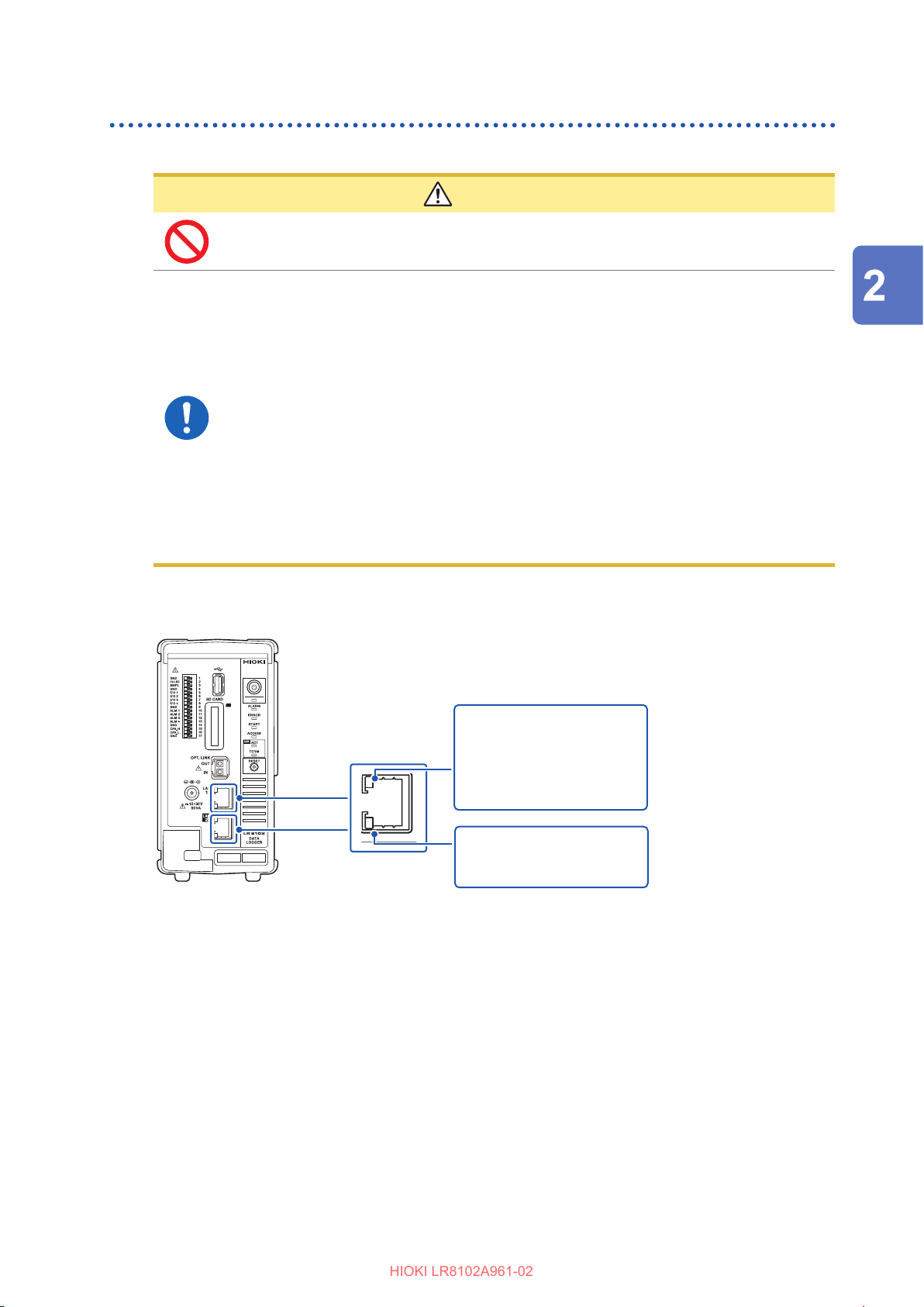
Connecting the instrument and a PC via LAN
HIOKI LR8102A961-02
Connect the instrument and a PC with a LAN cable.
CAUTION
Do not unplug the LAN cable while the instrument is sending or receiving data.
Doing so could damage the instrument and the PC.
Turn OFF the instrument and PC before connecting or disconnecting a LAN
cable.
Failure to do so could damage the instrument and the PC being connected or cause
them to malfunction.
Use the same ground for the instrument and the PC.
When a LAN cable is connected to the instrument with a potential dierence between
the ground circuits of the instrument and the PC, the instrument and PC may be
damaged or malfunction.
If routing a LAN cable outdoors or using a LAN cable longer than 30 m, attach
a LAN surge protector or other suitable protective device.
Setting and Connecting the LAN
Connection (Preparation for Measurements)
Failure to do so could cause damage to the instrument due to increased susceptibility
to the eects of induced lightning.
LAN port of the instrument
LINK LED (green)
RJ-45 connector
The LINK LED lights up when the instrument is properly connected to the network and available.
If the LED does not light up, the instrument or connected devices may have a problem or the LAN
cable may be broken.
• Lit: Connection
established
• Lamp
o:
ACT LED (orange)
Blinking: Sending/receiving
Connection not
established
data
95
Page 96
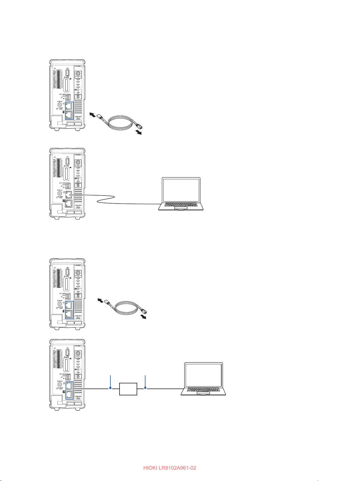
Setting and Connecting the LAN
HIOKI LR8102A961-02
When connecting one instrument and one PC
Required item: 9642 LAN Cable (1 piece)
9642 LAN Cable
1
To PC
2
Connect the 9642 LAN Cable
1
to the LAN1 or LAN2 port of
the instrument.
Connect the 9642 LAN Cable
2
to the PC’s LAN connector.
9642 LAN Cable
When connecting one PC and multiple instruments via a hub.
Required items: 9642 LAN Cable (2 pieces), hub
Connect the 9642 LAN Cable
1
to the LAN1 or LAN2 port of
the instrument.
Connect the 9642 LAN Cable
2
9642 LAN Cable
to the hub’s LAN connector.
1
2
To hub
96
9642 LAN Cable
Hub
Page 97
Setting and Connecting the LAN
HIOKI LR8102A961-02
Default connection settings for LAN1
The default IP address of the instrument on LAN1 is 192.168.1.2.
There are three methods to change the IP address on LAN1 and the communication settings of the
instrument as follows.
• Use the HTTP server
• Use the communication commands.
• Use Logger Utility.
To change the settings using the HTTP server
See “12.2 Remotely Operating the Instrument through the HTTP Server” (p. 313).
To change the settings using the communication commands.
Example: Connecting one instrument and one PC with the minimum settings required
Required items: 9642 LAN Cable (1 piece), PC with congurable IP address
Change the IP address of the PC to 192.168.1.1
Send the following communication commands from the PC (communication command port 8802)
Connection (Preparation for Measurements)
Set the IP address of the instrument.
1
The IP address is used to identify individual devices that are connected to the network. Ensure that
the instrument uses a unique name that is not being used by any other device on the network. If the
DHCP server is enabled, the setting will be congured automatically using the server.
Settings
Syntax Command
Example
Query
Syntax Query
Example
Parameter
ip1
ip2
ip3
ip4
0 to 255
0 to 255
0 to 255
0 to 255
:SYSTem:COMMunicate:LAN:IPADdress 192,168,1,100
:SYSTem:COMMunicate:LAN:UPDate
Response
:SYSTem:COMMunicate:LAN:IPADdress?
(Response)
:SYSTem:COMMunicate:LAN:IPADdress ip1,ip2,ip3,ip4
:SYSTem:COMMunicate:LAN:IPADdress?
ip1<NR1>,ip2<NR1>,ip3<NR1>,ip4<NR1>
:SYSTEM:COMMUNICATE:LAN:IPADDRESS 192,168,1,100
(When the header is ON)
97
Page 98
Setting and Connecting the LAN
HIOKI LR8102A961-02
Set the subnet mask of LAN1.
2
The subnet mask is used to separate the IP address into the portion that indicates the network and the portion
that indicates the device.
Ensure that the instrument uses the same subnet mask that is being used by other devices on the same
network. If the DHCP server is enabled, the setting will be congured automatically using the server.
Settings
Syntax Command
Example
Query
Syntax Query
Example
Parameter
:SYSTem:COMMunicate:LAN:SMASk 255,255,255,0
:SYSTem:COMMunicate:LAN:UPDate
Response
:SYSTem:COMMunicate:LAN:SMASk?
(Response)
:SYSTem:COMMunicate:LAN:SMASk mask1,mask2,mask3,
mask4
:SYSTem:COMMunicate:LAN:SMASk?
mask1<NR1>,mask2<NR1>,mask3<NR1>,mask4<NR1>
:SYSTEM:COMMUNICATE:LAN:SMASK 255,255,255,0
(When the header is ON)
mask1
mask2
mask3
mask4
Updates the settings of LAN1.
3
Settings
Syntax Command
Example
Change the PC to be used or change the IP address of the PC (as needed).
4
0 to 255
0 to 255
0 to 255
0 to 255
:SYSTem:COMMunicate:LAN:UPDate
:SYSTem:COMMunicate:LAN:UPDate
• If the intended use of the PC is only to set the IP address of the instrument, replace the PC as
needed.
• Change the IP address of the PC as well if it becomes necessary as a result of setting the IP
address of the instrument.
Changing the settings using Logger Utility
Required items: 9642 LAN Cable (1 piece), PC on which Logger Utility can be installed
Install Logger Utility on the PC.
1
Refer to the “Logger Utility Instruction Manual” (PDF le) on the provided DVD.
Start up Logger Utility.
2
Click [All Programs] > [HIOKI] > [Logger Utility].
98
Page 99
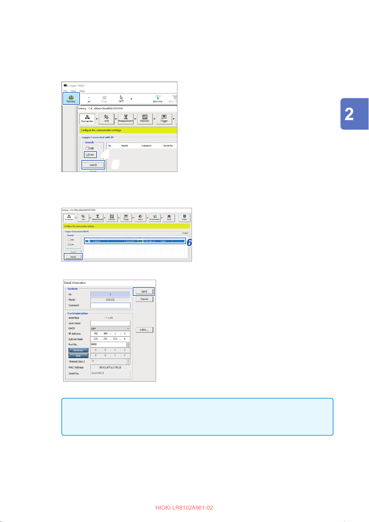
Click [Setting].
HIOKI LR8102A961-02
3
The settings screen is displayed.
Check the [LAN] checkbox.
4
Click [Search].
5
Select the target instrument.
6
Click [Details].
7
The [Detail Information] dialog box is displayed.
Setting and Connecting the LAN
Connection (Preparation for Measurements)
Congure the network settings and click [Send].
8
Change the IP address of the PC. (as needed).
9
IMPORTANT
If the DHCP setting for the instrument is set to ON in an environment where the DHCP server is
not operating, the instrument cannot be searched for with Logger Utility. Connect the instrument
in an environment with the DHCP server operating, or fully reset the instrument.
99
Page 100

Setting and Connecting the LAN
HIOKI LR8102A961-02
When the LAN communications cannot be established.
The cable is not connected properly
• There may be a contact failure in the connector. Disconnect and then connect the cable again.
• When the cable is connected properly, the LINK LED of the LAN1 or LAN2 port of the instrument
lights up.
The IP address of the PC is not correct
The IP address, subnet mask, and gateway address of the network interface of the PC can be
checked.
Press the Windows and R keys simultaneously.
1
The [Run] dialog box is displayed.
Enter “CMD” and press the Enter key.
2
The [CMD.exe] window will open.
After the cursor starts blinking, enter [ipcong/all] and press the Enter key.
3
The communications between the instrument and the PC cannot be established
If the IP addresses of the instrument and the PC are set correctly, you can use the ping protocol to
check whether the transmission from the PC reaches the instrument.
Press the Windows and R keys simultaneously.
1
The [Run] dialog box is displayed.
Enter “CMD” and press the Enter key.
2
The [CMD.exe] window will open.
After the cursor starts blinking, enter [ping XXX.XXX.X.X] (IP address of the host to be
3
checked) and press the Enter key.
The host name can also be used in an environment where the DNS is functioning normally.
For example, enter [ping 192.168.1.2] if the IP address of the instrument is [192.168.1.2].
Check the contents displayed on the PC screen.
4
The communications are normal if the following is displayed on the PC screen. “Time”
represents the time spent for the communications.
Pinging 192.168.1.2 with 32 bytes of data:
Reply from 192.168.1.2: bytes=32 time<10ms TTL=32
Reply from 192.168.1.2: bytes=32 time<10ms TTL=32
Reply from 192.168.1.2: bytes=32 time<10ms TTL=32
Reply from 192.168.1.2: bytes=32 time=1ms TTL=32
The communications are not normal if the following is displayed on the PC screen. Check the
cable connection.
Pinging 192.168.1.2 with 32 bytes of data:
Reply from 192.168.1.2: Host is down.
Reply from 192.168.1.2: Host is down.
Reply from 192.168.1.2: Host is down.
Reply from 192.168.1.2: Host is down.
100
 Loading...