

Page 1
LR5041
HIOKI LR5041B980-06
LR5042
LR5043
VOLTAGE LOGGER
Instruction Manual
Read carefully before use.
Keep for future reference.
When using the instrument for the
rst time
Part Names/Functions
and Display Indicators
Settings List
p.12
p.29 Error Displays
June 2022 Revised edition 6
LR5041B980-06 22-06H
Troubleshooting
Maintenance and Service
Troubleshooting
[600329176]
p.91
p.92
p.94
EN
Find Quality Products Online at: [email protected]
www.GlobalTestSupply.com
Page 2

Contents
Introduction ..............................................................................1
HIOKI LR5041B980-06
Verifying Package Contents....................................................3
Safety Information....................................................................5
Operating Precautions.............................................................6
Measurement Preparation to Data Analysis ..........................8
Chapter 1
Overview__________________________________ 11
1.1 Product Overview and Features .............................11
1.2 Part Names/Functions and Display Indicators .....12
1.3 Display Organization ...............................................14
Chapter 2
Measurement Preparations___________________17
2.1 Installing (or Replacing) the Battery ......................17
2.2 Connecting a Connection Cable ............................20
2.3 Installing the PC Application Program ..................23
i
Contents
Chapter 3
Settings___________________________________29
3.1 Settings List .............................................................29
3.2 Making Settings on the Logger ..............................31
3.3 Making Settings from the LR5000 Utility
Program ............................. .......................... ............. 36
Chapter 4
Measurement and Analysis___________________ 43
4.1 Pre-Measurement Inspection .................................43
4.2 Installing the Logger ...............................................44
4.3 Starting and Stopping Recording ..........................46
4.4 Confirming Currently Measured Values and Data
Recording .......................... .......................... ............. 49
LR5041B980-06
Find Quality Products Online at: [email protected]
www.GlobalTestSupply.com
Page 3

ii
HIOKI LR5041B980-06
Contents
4.5 Automatically Importing (Saving) Recorded Data
to a Computer, and Graph Display ........................ 49
4.6 Manually Importing (Saving) Recorded Dat a to a
Computer, and Graph Display ........ ....................... 59
4.7 Displaying a Graph of Saved Recording Data ..... 62
4.8 Printing Recorded Data .......................................... 64
Chapter 5
Processing Recorded Data ___________________65
5.1 Scaling ................................................................ ..... 67
5.2 Calculating Electric Power ......... .. ... ....................... 68
5.3 Calculating Energy Cost ........................................ 69
5.4 Calculating Operating Rate .................................... 70
5.5 Integration ............................................................... 71
5.6 Calculating Dew-Point Temperature ..................... 72
5.7 Two-Data-Item Arithmetic Calculations ................ 73
5.8 Converting Over-Threshold Data Values .............. 74
Chapter 6
Organizing Data ____________________________75
6.1 Copying and Moving Data ...................................... 76
6.2 Deleting Data ....................... ... ................................. 77
6.3 Combining Data ...................................................... 78
6.4 Extracting Data ....................................................... 79
Chapter 7
Options Settings (LR5000 Utility Program) ______81
7.1
Changing the Saving Method for Imported Data
7.2 Changing the Connection Monitoring Method,
and Logger Settings Displays ............................... 83
... 82
Chapter 8
Specifications______________________________85
8.1 Measurement Specifications ................................. 85
8.2 Functional Specifications ...................................... 86
Find Quality Products Online at: [email protected]
www.GlobalTestSupply.com
Page 4

8.3 Miscellaneous ..........................................................87
HIOKI LR5041B980-06
8.4
LR5091 Communication Adapter Specifications
...88
Chapter 9
Maintenance and Service ____________________91
9.1 Cleaning ...................................................................92
9.2 Disposing of the Logger .........................................92
9.3 Troubleshooting ......................................................92
9.4 Error Displays ...... ... .................................................94
Appendix_________________________________ A 1
Appendix 1 About Recording Modes.............................. A 1
Appendix 2 Recording Intervals and Maximum
Recording Times....................... ... ... .............A 2
Appendix 3 Battery Life Approximation......................... A 2
Index _________________________________Index 1
iii
Contents
Find Quality Products Online at: [email protected]
www.GlobalTestSupply.com
Page 5
Introduction
HIOKI LR5041B980-06
Introduction
Thank you for purchasing the HIOKI Model LR5041, LR5042, LR5043 Voltage Logger. To obtain maximum performance from the logger, please read this manual
first, and keep it handy for future reference.
The latest edition of the instruction manual
1
The contents of this manual are subject to change,
result of product improvements or changes to specifications.
The latest edition can be downloaded from Hioki’s website.
for example as a
Trademarks
Microsoft and Excel are either registered trademarks or trademarks of Microsoft Corporation in the United States and other countries.
Notation
Indicates a prohibited action.
(p. ) Indicates the location of reference information.
Indicates the location of reference information.
* Indicates that descriptive information is provided below.
[ ]
SET
(Bold charac-
ters)
Menus, commands, dialogs, buttons in a dialog, and other
names on the screen and the keys are indicated in brackets.
Bold characters within the text indicate operating button
labels.
Windows
Unless otherwise specified, “Windows” represents Windows 7 or Windows 10.
Find Quality Products Online at: [email protected]
www.GlobalTestSupply.com
Page 6
2
HIOKI LR5041B980-06
Introduction
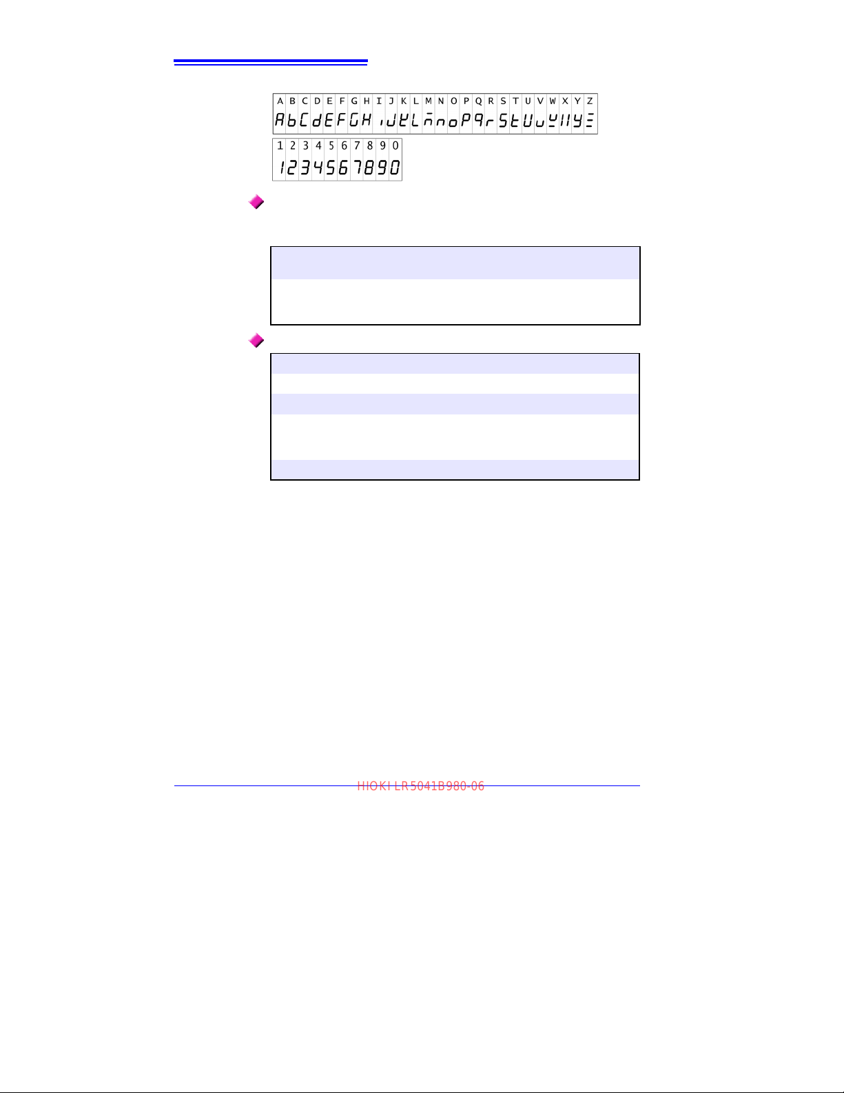
The screen of this logger displays characters in the following manner.
Accuracy
We define measurement tolerances in terms of rdg. (reading) and dgt.
(digit) values, with the following m
rdg.
(reading or displayed value)
dgt.
(resolution)
The value currently being measured and indicated
on the measuring instrument.
The smallest displayable unit on a digital measuring
instrument, i.e., the
tal display to show a "1" as the least-significant digit.
eanings:
input value that causes the digi-
Mouse Operation
Click Press and quickly release the left button of the mouse.
Right-click
Double click Quickly click the left button of the mouse twice.
Drag
Activate Click on a window on the screen to activate that window.
Press and quickly release the right button of the mouse.
While holding down the left button of the mouse, move the
mouse and then release the left button to deposit the chosen
item in the desired position.
Find Quality Products Online at: [email protected]
www.GlobalTestSupply.com
Page 7
Verifying Package Contents
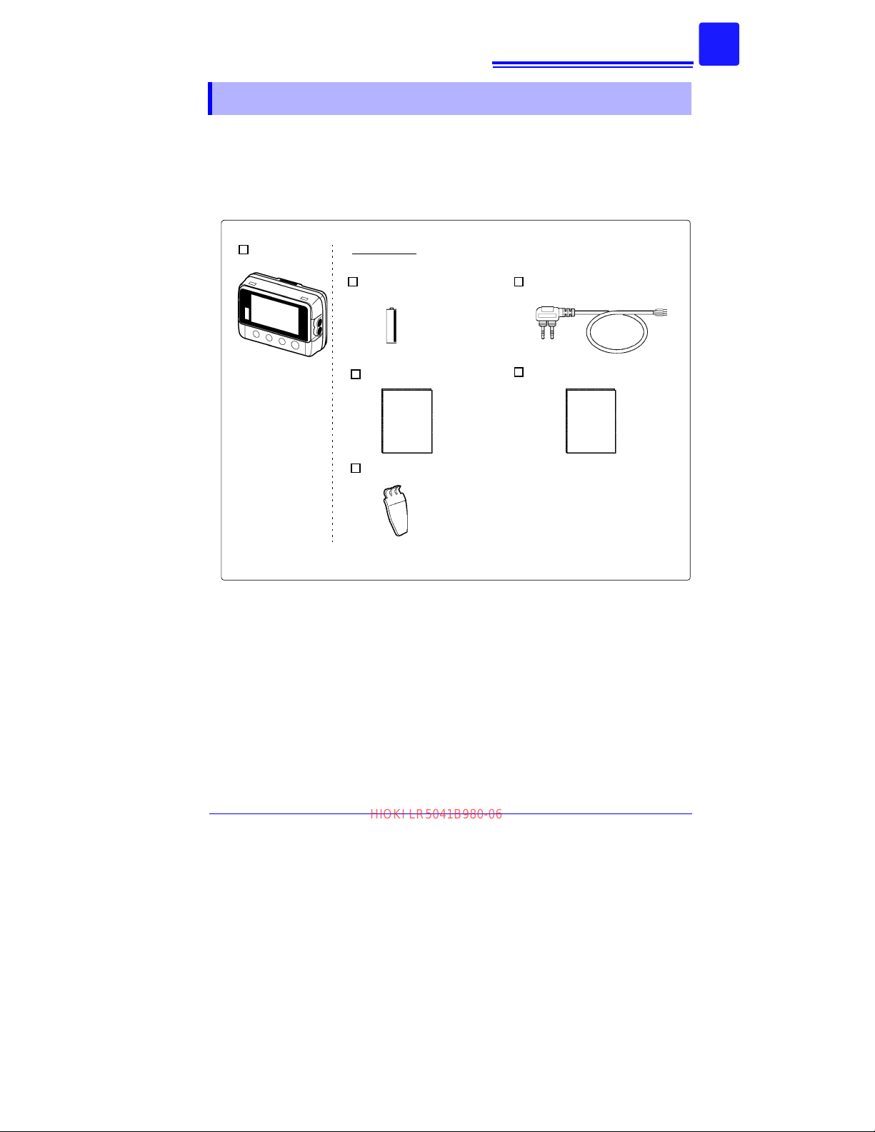
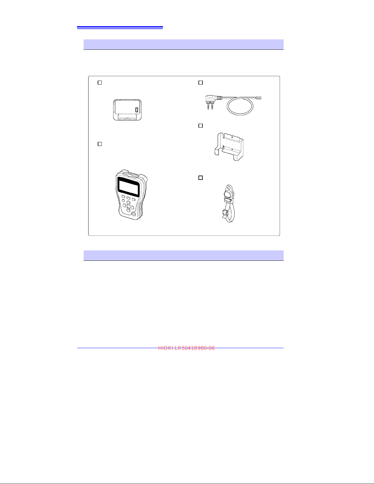
Logger (1)
LR6 alkaline battery (1)
(Pre-installed in the logger.)
Accessories
See: Other specified options:"Options" (p.4)
LR9802 Connection Cable (1)
Instruction Manual (1)
Operation Manual (1)
Stand (1)
HIOKI LR5041B980-06
Verifying Package Contents
When you receive the logger, inspect it carefully to ensure that no damage
occurred during shipping. In particular, check the accessories, pa nel swit ches, and
connectors. If damage is evident, or if it fails to operate according to the specifications, contact your dealer or Hioki representative.
Quantities in parentheses ( ).
3
Find Quality Products Online at: [email protected]
www.GlobalTestSupply.com
Page 8
4
LR5092-20 Data Collector
(Includes LR5000 Utility Program* CD [PC
application software], LR03 alkaline battery
x2, Instruction manual, Operation manual,
and USB Cable)
LR9802 Connection Cable
(Cable length: Approx. 1 m)
LR5091 Communication Adapter(1)
(Includes LR5000 Utility Program* CD [PC
application software] and USB Cable)
* :The latest version can be downloaded
from our web site.
See: LR5091 spec ificati on: (p.88)
LR9901 Wall-Mounted Holder
Z5004 Magnetic Strap
See: Method of mounting: (p.45)
See: Method of mounting: (p.45)
HIOKI LR5041B980-06
Verifying Package Contents
Options
The options listed below are available for the instrument. To order an option, please
contact your authorized Hioki distributor or reseller. Options are subject to change.
Please check Hioki's website for the latest information.
Transporting Precautions
Use the original packing mater ials when transporting the logger, if possible.
Pack the lo
description of existing damage. We do not take any responsibility for damage incurred
during shipping.
gger so that it will not sustain damage during shipping, and include a
Find Quality Products Online at: [email protected]
www.GlobalTestSupply.com
Page 9
Safety Information
HIOKI LR5041B980-06
Safety Information
This manual contains information and warnings essential for safe operation of the
logger and for maintaining it in safe operating condition. Before using it, be sure to
carefully read the following safety precautions.
This logger is designed to comply with IEC 61010 Safety Standards, and
has been thoroughly tested for safety prior to shipment. However, mishandling during use could result i n injury or death, as
the logger.
manual may negate the provided safety features.
Be certain that you understand the instr
manual
ries not resulting directly from logger defects.
However, using the lo gge r in a way not described in this
before use. We disclaim any responsibility for accidents or inju-
Safety Symbols
Markings on the logger have the following meanings.
In the manual, the symbol indicates particularly important i nformation that the user should read before using the logger.
The symbol printed on the logger ind icates that the user should
refer to a corresponding topic in the manual (marked with the
symbol) before using the relevant function.
Indicates DC (Direct Current).
uctions and precautions in the
well as damage to
5
Symbols for Various Sta ndards
Markings on the logger have the following meanings.
Indicates that the product conforms to regulations set out by the EU
Directive.
This symbol indicates that the product conforms to safety r egulations set out by the EC Directive.
Danger Levels
The following symbols in this manual indicate the rela tive importance of cautio ns and warnings.
Indicates that incorrect operation presents an extreme hazard
that could result in serious injury or death to the user.
Indicates that incorrect operation p
that could result in serious injury or death to the user.
Indicates that incorrect operation pre
injury to the user or damage to the logger.
Indicates advisory items related to performance or correct
operation of the
logger.
resents a significant hazard
sents a possibility of
Find Quality Products Online at: [email protected]
www.GlobalTestSupply.com
Page 10
6
HIOKI LR5041B980-06
Operating Precautions
Operating Precautions
Follow these precautions to ensure safe operation and to obtain the full benefits of the various fun
Installation Precautions
Operating temperature and humidity: -20 to70°C (-4.0 to 158.0°F), 80%RH or less
Storage temperature and humidity : -20 to70°C (-4.0 to 158.0°F), 80%RH or less
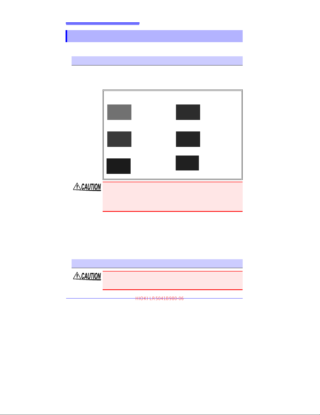
Avoid the following locations that could cause an accident or damage to the logger.
ctions.
(non-condensating)
(non-condensating)
Exposed to direct
sunlight
Exposed to high temperature
Exposed to oil, other
chemicals, or sol
Exposed t
humidity or condensa-
on
ti
Subject to vibration
vents
o high
In the presence of
corrosive or explosive
gases
Exposed to strong
romagnetic
elect
fi
elds
Near electromagnetic
radiators
Near induction heating systems
(e.g., high-frequency
ction heating sys-
indu
t
ems and IH cooking
utensils)
• The protection rating for the enclosure of this device (based on
EN60529) is *IP54.
• Although this logger is designed to resist the ingress of dust and
water, it is not entirely water- or dust-proof, so to avoid shock or damage, do not use it in a wet or dusty environment.
*IP54 :This indicates the degree of protection provided by the enclosure of the
device against use in hazardous locations, entry of solid foreign objects,
and the ingress of water.
5 : Protected against access to hazard
mm in diameter. Dust-proof type (The penetration of dust cannot be prevented completely, but quantities of dust that may hin
eration of equipment or safety cannot pene
4 : The equipment inside the enclosure is protected against the harmful ef-
fects of water splashed against the enclosure from any direction.
ous parts wi
th wire measuring 1.0
der the stated op-
trate the encl
osure.Åj
Avoiding Logger Damage
To avoid damage to the logger, protect it from physical shock when
transporting and handling. Be especially careful to avoid physical shock
from dropping.
Find Quality Products Online at: [email protected]
www.GlobalTestSupply.com
Page 11
Operating Precautions
HIOKI LR5041B980-06
CD Handling
• Always hold the disc by the edges, so as not to make fingerprints on
the disc or scratch the printing.Never touch the recorded side of the
disc. Do not place the disc directly on anything hard.
• Do not wet the disc with volatile alcohol or water, as there is a possibility of the label printing disappearing.
• To write on the disc label surface, use a spirit-based felt pen. Do not
use a
ball-point pen or hard-tipped pen, because there is a danger of
scratching the surface and corrupting the data. Do not use adhesive
labels.
• Do not expose the disc directly to the sun's rays, or keep it in conditions of high temperature or humidity, as there is a danger of warping,
with
consequent loss of data.
• To remove dirt, dust, or fingerprints from the disc, wipe with a dry
cloth, or use a CD cleaner. Always wipe from the inside to the outside,
and do no wipe with circular movements. Never use abrasives or solvent cleaners.
• Hioki shall not be held liable for any problems with a computer system
th
at arises
purchase of a Hioki product.
from the use of this CD, or for any problem related to the
Preliminary Checks
Before using the logger the first time, verify that it operates normally to ensure that the
no damage occurred during storage or shipping. If you find any damage, contact your
dealer or Hioki representative.
7
Before using the logger, make sure that the insulation on the connection cables is undama
improperly exposed. Using the logger in such conditions could
cause an electric shock, so contact your dealer or Hioki representative for replacements.
ged and that no bare conductors are
Find Quality Products Online at: [email protected]
www.GlobalTestSupply.com
Page 12
8
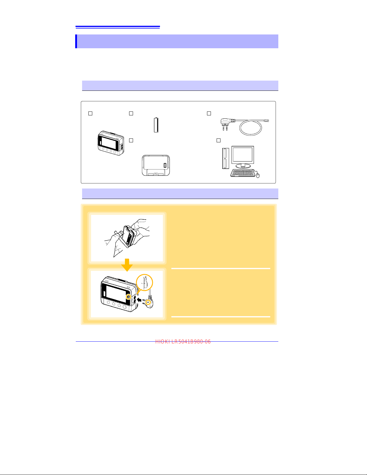
Logger (1) LR6 alkaline battery (1) LR9802 Connection Cable (1)
LR5091 Communication Adapter (1)
(LR5000 Utility Program* CD [PC application software] and USB Cable)
Computer (1)
1
Install the battery in the logger.
See: "2.1 " (p.17)
2
Connect the LR9802 Connection Cable to
the logger.
See: "2.2 " (p.20)
1
2
HIOKI LR5041B980-06
Measurement Preparation to Data Analysis
Measurement Preparation to Data Analysis
The steps from measurement preparation to data analysis are illustrated with a typical measurement example.
Example Case: Record a factory flow sensor output signal (1-5
intervals for one month, and store the data on a computer.
Required Items:
Quantities in parentheses ( ).
V) at one-minute
Procedure:
Find Quality Products Online at: [email protected]
www.GlobalTestSupply.com
Page 13
Measurement Preparation to Data Analysis
3
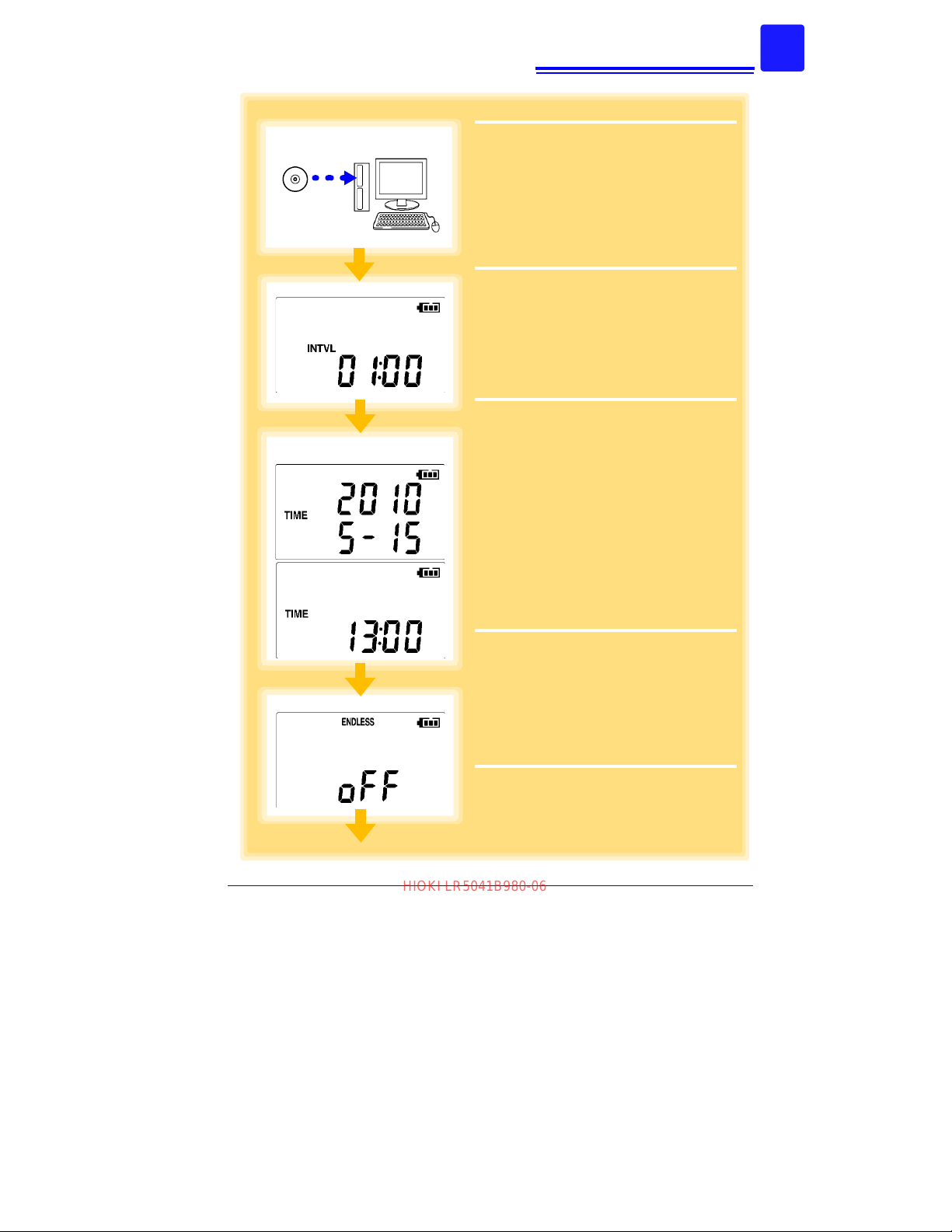
Install the LR5000 Utility Program on the
computer.
See: "2.3" (p.23)
4
Select the recording interval for the logger
(in this case, 1 minute).
See: "Recording Interval Setting" (p.31)
(The setting can be made also from the
LR5000 Utility Program.) (p.39)
5
Set the logger to the correct date and time
(in this case, 15 May 2010, 13:00).
See: "Real-Time Clock Setting" (p.32)
(With the LR5000 Utility Program, the logger can be set to the computer time.)
(p.42)
6
Set the stop method to [OFF].
(This setting provides one-time measurement:
recording stops when memory becomes full.)
See:
"Stop Method Setting (for when
memory becomes full)" (p.33)
(The setting can be made also from the
LR5000 Utility Program.) (p.39)
5
4
3
6
HIOKI LR5041B980-06
9
Find Quality Products Online at: [email protected]
www.GlobalTestSupply.com
Page 14
10
7
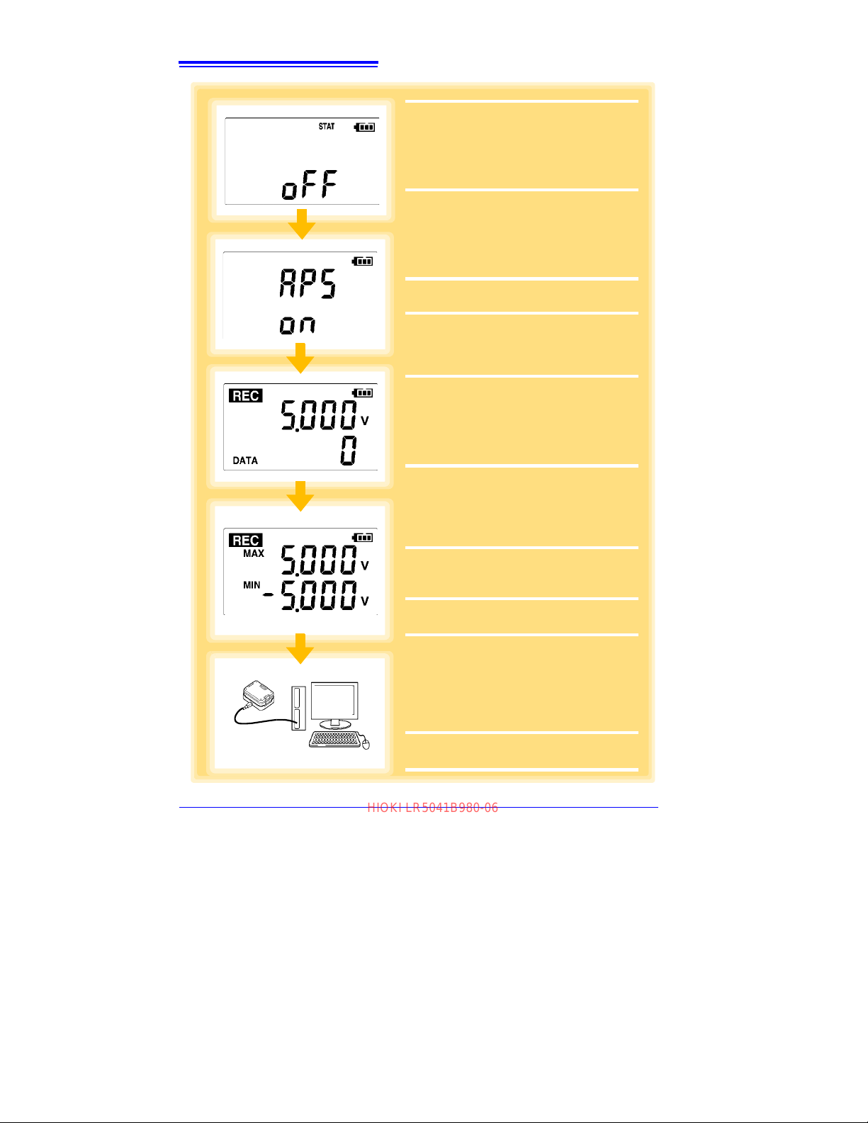
Set the recording mode to [OFF].
(This setting provides instantaneous measurement.)
See:
"Recording Mode Setting" (p.34)
(The setting can be made also from the
LR5000 Utility Program.) (p.39)
8
Set the power save setting to [ON].
(The on (enabled) setting is recommended
for long-term recording.)
See:
"Power Save Setting" (p.34)
(The setting can be made also from the
LR5000 Utility Program.) (p.38)
9
Pre-measurement inspection (p.43)
10
Install the logger at the measurement
site in the factory.
See: "4.2" (p.44)
(It can be wall-mounted.)
11
Hold REC/STOP on the logger for two
seconds to start recording.
(Confirm that the recording data count is
incrementing and that recording is actually
occurring.)
See:
"4.3" (p.46)
12
Switch the logger display by pressing the
(+) and (-) buttons to check maximum
and minimum recorded values.
(Confirm that recording is actually occurring.)
See:
"4.4" (p.49)
13
After a month, hold REC/STOP on the logger again for two seconds to stop recording.
See: "4.3" (p.46)
14
Retrieve the logger from the measurement site.
15
Import recorded data from the logger to
a connected computer. For analysis, display the data in a graph.
See: "4.5" (p.49)
(The data is automatically saved when
imported to the computer. By default, it is
also automatically displayed in a graph.)
16
Print recorded data as needed.
See: "4.8" (p.64)
8
11
7
15
12
(LR5042 Example)
HIOKI LR5041B980-06
Measurement Preparation to Data Analysis
Find Quality Products Online at: [email protected]
www.GlobalTestSupply.com
Page 15
11
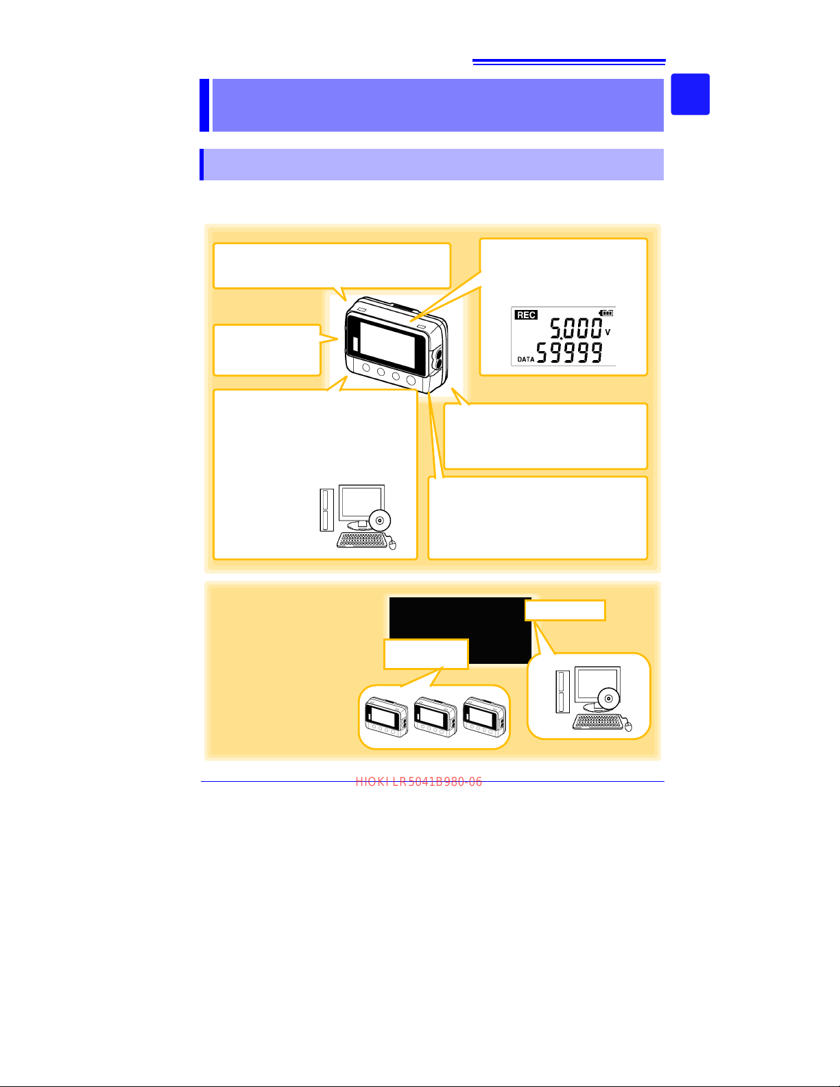
Advanced functions included
• Record statistical values(p.33), (p.39)
• Scaling (p.40), (p.67)
• Alarm display (p.41)
• Preheat output (p.35)
• Data can be imported while recording.
• Records up to 60,000 measurements
Splash-proof
ingress protection
(IP54)
Large display shows measured DC voltage value and
recorded data count
Measures DC voltage (one channel).
Browse and manage data with
LR5000 Utility Program on a PC.
The LR5000 Utility Program PC application is very easy to install.
After installation, data management and
browsing is easy with auto-start, data display and saving.
• Data is preserved independently
of battery state
• Recording continues (for approx.
30 s) during battery replacement
Measurement
Sites
Analysis Site
Measures the output of various sensors in the factory
Suitable for ESCO, ISO, and similar measurement applications.
HIOKI LR5041B980-06
1.1 Product Overview and Features
Overview Chapter 1
1.1 Product Overview and Features
This instrument is a compact portable data logger for measuring, displaying, and
recording DC voltage.
1
Chapter 1 Overview
3
Find Quality Products Online at: [email protected]
www.GlobalTestSupply.com
Page 16
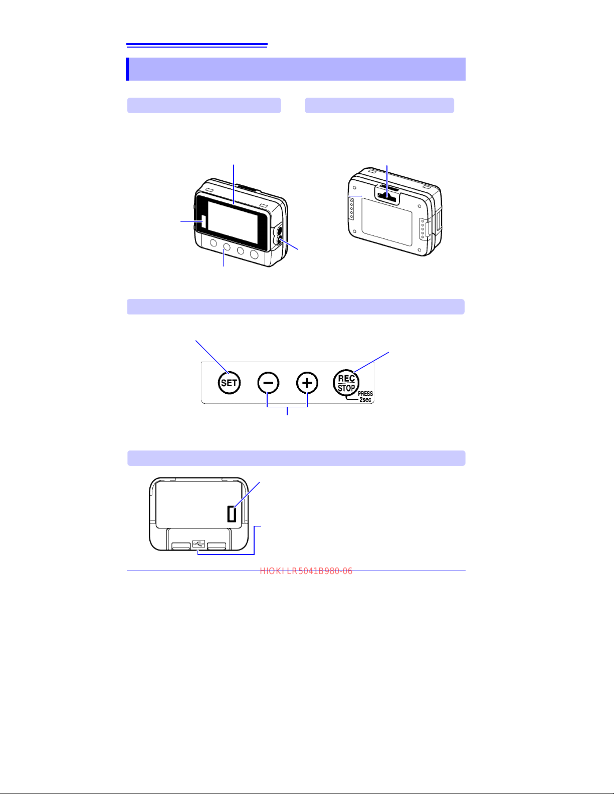
12
IR Port
(p.49)
Communicates
with the LR5091
Communication
Adapter or
LR5092-20 Data
Collector
Front
LCD (p.13)
The display blanks after 30 seconds of operator inactivity (auto power save).The display
reappears by pressing a button.
When the display is visible, it refreshes about
once per second.
Battery Cover
(p.17)
SET button
Displays settings.
Back
Operation Buttons
(-) button, (+) button
Changes Measurement display contents.
Changes setting values on the Settings display.
Connection cable Jacks
(p.20)
Connect a connection cable.
Operation buttons
LR5091 Communication Adapter
IR Port (p.49)
Communicates with the logger.
USB Port (p.36)
Connect a USB cable here to communicate with a computer.
(Mini-B receptacle)
Stand/Strap Attachment Hole (p.44)
Attach the logger to a wall or other surface by
hanging it on a screw. (Supported screw head
dimensions: up to approx. 6.8 mm in diameter
and approx. 2.5 mm in thickness)
REC/STOP button
Hold for two seconds to start/stop recording.
From a setting display, switches to measurement
display.
HIOKI LR5041B980-06
1.2 Part Names/Functions and Display Indicators
1.2 Part Names/Functions and Display Indicators
Find Quality Products Online at: [email protected]
www.GlobalTestSupply.com
Page 17
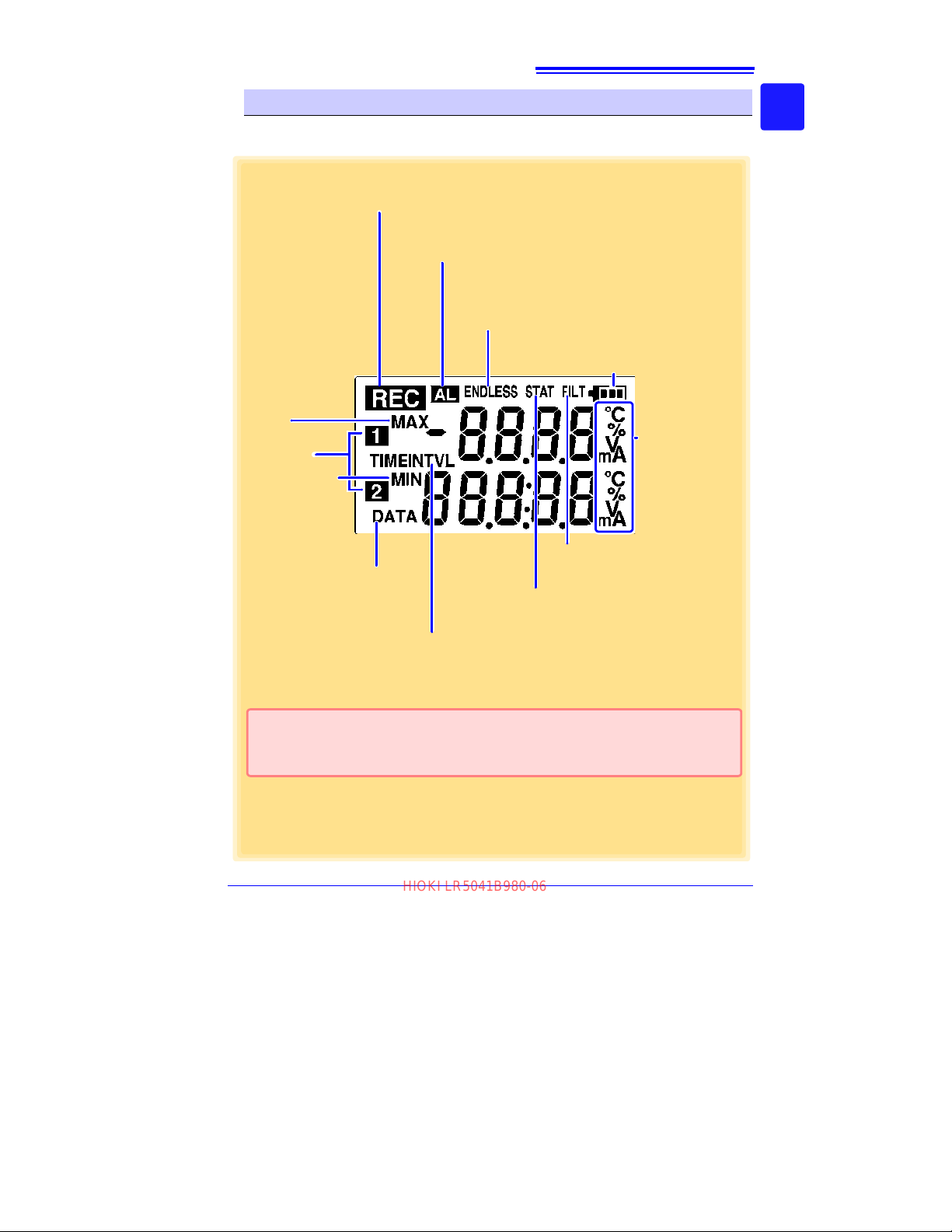
13
ENDLESS indicator
Indicates the Stop Method Setting display.
Also appears on the Measurement display to indicate
endless recording (p.33) is enabled.
STAT indicator
Indicates the Recording Mode Setting display.
Also appears on the Measurement display to
indicate statistic recording (p.34) is enabled.
Not used by the logger.
Battery Status Indicator
Indicates the battery charge status. (p.18)
* Setting is available from the LR5000 Utility Program or via the LR5092-20 Data Col-
lector.
See: "3.3 Making Settings fro m the LR 5000 Utility Program" (p.36),
LR5092-20 Data Collector Instruction Manual
REC Indicator
Indicates recording in progress. (Blinks when waiting to record.)
AL indicator
When the alarm* function is enabled, this indicates when a measured value is outside of the specified (upper/lower value*) range.
Measurement
Channel
MAX indicator
Indicates that the
value displayed at
the right is the maximum.
MIN indicator
Indicates that the
value displayed
at the right is the
minimum.
DATA indicator
Indicates that the value displayed
at the right is the data count.
TIME indicator
Indicates the Date-Time Setting display.
INTVL indicator
Indicates the Recording Interval Setting display.
Units
Indicates the unit of
measurement on
each channel.
(not displayed when
scaling* is enabled)
HIOKI LR5041B980-06
1.2 Part Names/Functions and Display Indicators
Display Indicators
The display indicators provide the following information.
1
Chapter 1 Overview
3
Find Quality Products Online at: [email protected]
www.GlobalTestSupply.com
Page 18
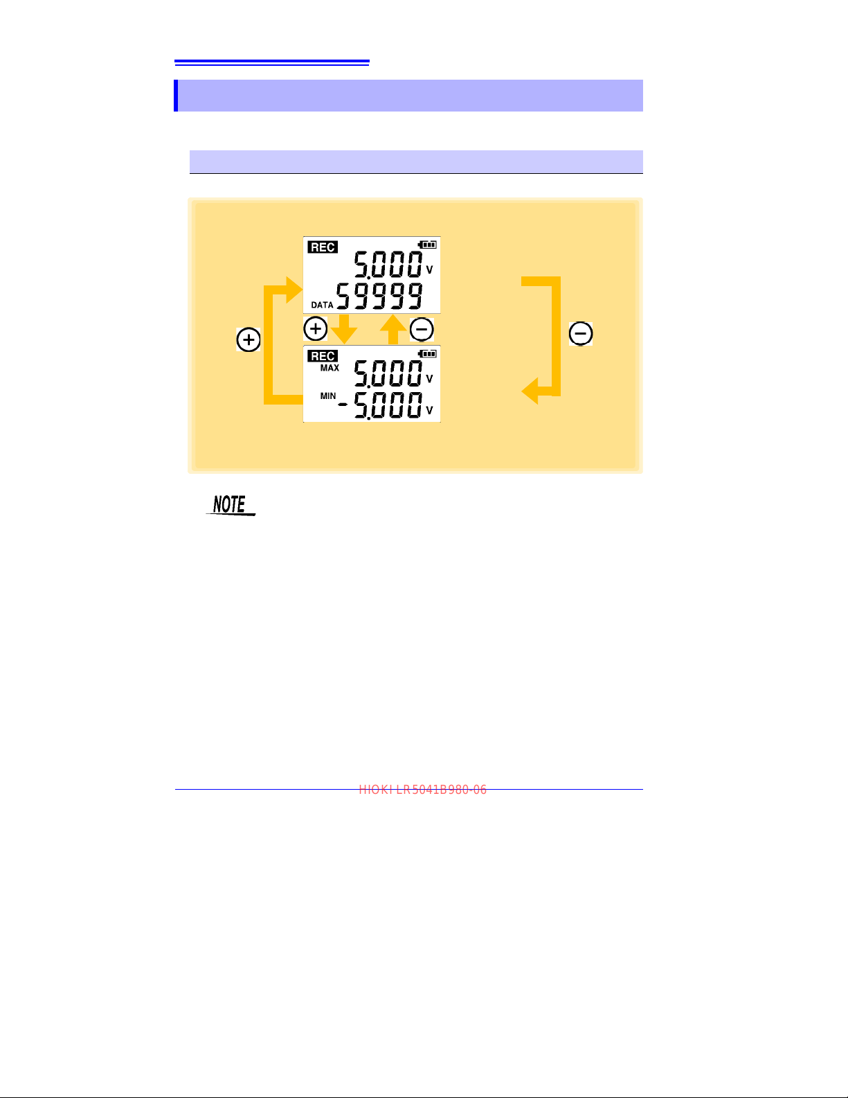
14
Measured value
Recorded data
count
Maximum value
Minimum value
(LR5042 Display Example)
HIOKI LR5041B980-06
1.3 Display Organization
1.3 Display Organization
The logger has two general display types: Measurement and Settings.
Measuring display
The (+) and (-) buttons switch the display type.
• For instantaneous recording, the maximum and minimum values are
obtained from all the data measured at each recording interval.
• For statistical recording, the maximum and minimum values are
obtained from all the data measured every second.
• The maximum and minimum values are not displayed when the
recorded data count is 0.
Find Quality Products Online at: [email protected]
www.GlobalTestSupply.com
Page 19
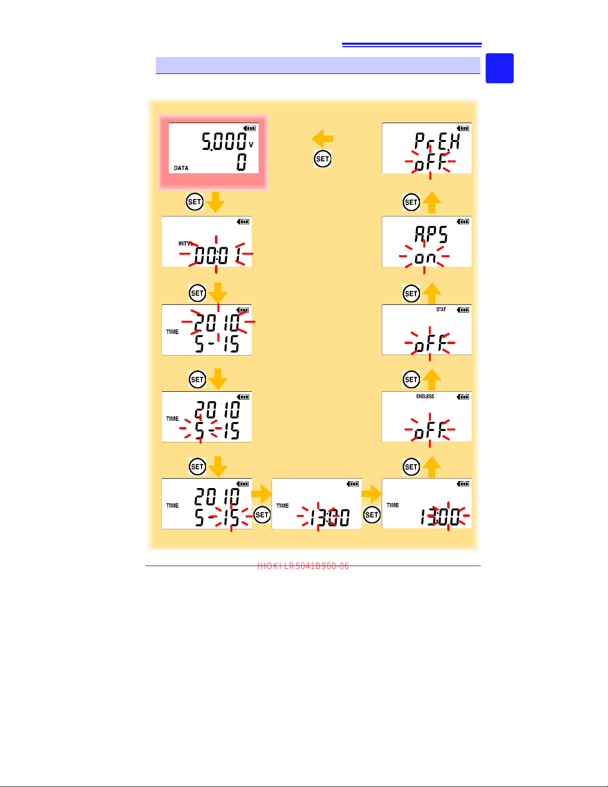
15
Recording Interval Setting
(p.31)
Month Setting (p.32)
Day Setting (p.32)
Minute Setting (p.32)
Measuring display
Battery life is extended when on
(enabled).
(Default is on.)
See:
"Appendix 3 Battery
Life Approximation"
(p.A2)
When on (statistical recording), instantaneous, maximum, minimum,
and average values are recorded at
each interval. Battery life is shorter.
(Default is off.)
(Record instantaneous values)
See:
"Appendix 3 Battery Life
Approximation" (p.A2)
Select what happens when memory
becomes full.
When on, the oldest data is overwritten, and when off, recording stops.
(Default is on.)
(LR5042 Display Example)
Power Save Setting (p.34)
Preheat Time Setting (p.35)
Recording Mode Setting
(p.34)
Stop Method Setting (p.33)
Hour Setting (p.32)
Year Setting (p.32)
HIOKI LR5041B980-06
1.3 Display Organization
Setting display
Select the display with the SET button. Press (+) and (-) to change a setting.
Press the REC/STOP button to switch to the Measurement display from any other.
1
Chapter 1 Overview
3
Find Quality Products Online at: [email protected]
www.GlobalTestSupply.com
Page 20

16
HIOKI LR5041B980-06
1.3 Display Organization
• When no operation occurs for 30 seconds with the Settings display,
automatically switches to Measurement display.
• When the battery indicator appears, settings cannot be changed
(although they can still be displayed).
• Settings cannot be changed while recording. However, settings can
still be displayed by pressing the SET button from the Measurement
display.
Find Quality Products Online at: [email protected]
www.GlobalTestSupply.com
Page 21
Measurement
1. All segments
2. Model name 3. Firmware version
4. Year Setting display
HIOKI LR5041B980-06
17
2.1 Installing (or Replacing) the Battery
Preparations
Chapter 2
2.1 Installing (or Replacing) the Battery
• After replacing the battery, replace the cover before using the logger.
• Be sure to insert them with the correct pola
performance or damage from battery leakage could result.
Replace batteries only with the specified type.
• Battery may explode if mistreated. Do not short-circuit, recharge,
disassemble or dispose of in fire.
• Handle and dispose of batteries in accordance with local regulations.
• Data and settings stored in the logger are retained even when the battery is depleted, and during battery replacement.
• The clock can keep good time for several minutes even when the battery is removed during a battery change.
• Once the battery indicator appears, operation can still continue for
about 30 seconds when the battery is removed during recording.
• Testing monitor batteries installed in the unit may possibly be weak.
Replace batteries before extended measurement usage.
• Use only LR03 Alkaline batteries. Using manganese batteries may not
result in accurate measurements or proper communication with the
LR5091 Communication Adapter and LR5092-20 Data Collector.
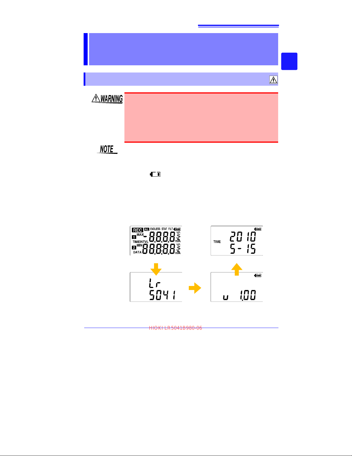
• After installing the batteries, the following displays appear, and the
date and time need t
o be set. (p.32)
rity. Otherwise, poor
2
Chapter 2 Measurement Preparations
3
Find Quality Products Online at: [email protected]
www.GlobalTestSupply.com
Page 22
18
HIOKI LR5041B980-06
2.1 Installing (or Replacing) the Battery
• When the battery indicator appears, settings cannot be changed
(although they can still be displayed).
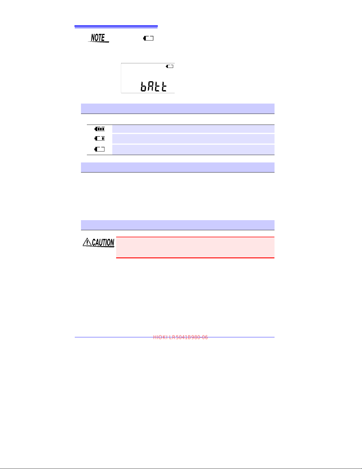
• When battery voltage is too low to operate the logger, the following
appears. Replace the battery to restore normal operation.
Battery Status Indicator
This indicator is displayed at the top right corner.
Battery charge remains. Fewer blocks within the indicator signify weaker battery charge.
Replace the discharged battery as soon as possible. (Even when the battery is removed
during recording, operation can continue for about 30 seconds.)
In this state, recording and communication with the LR5091 Communication Adapterr
and LR5092-20 Data Collector are not possible.
Using a NiMH Battery
The battery status indicator does not accurately show the remaining battery capacity
when usin
ity, charging conditions and repeated uses. Please take note of these points when
using it.
The device's battery status display and battery life are based on the usage of a brandnew alkaline battery.
g a NiMH battery. Moreover, the battery life will vary greatly with the capac-
When the logger will not be used for long time
To avoid corrosion and damage to this instrument from battery leakage,
remove the batteries from the instrument if it is to be stored for a long
time (1 week).
Find Quality Products Online at: [email protected]
www.GlobalTestSupply.com
Page 23
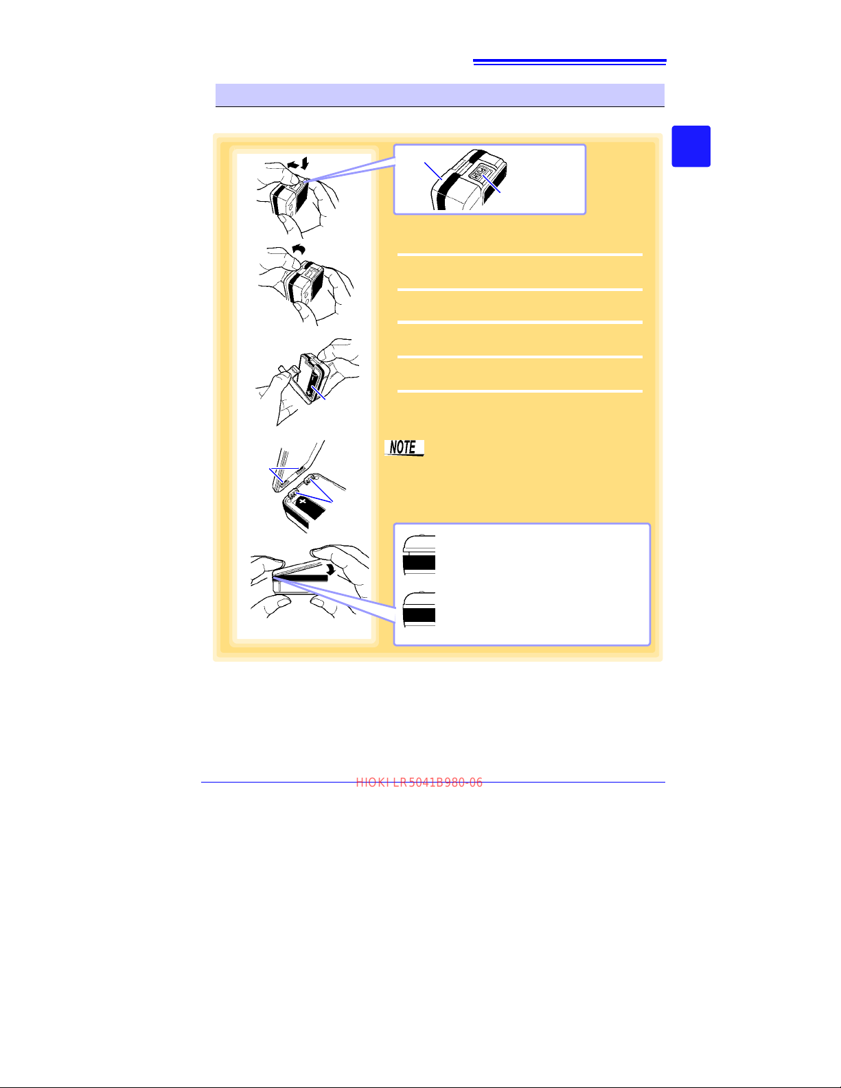
Battery Replacement
1
3
The cover will not close correctly if
there are any gaps.
Never attempt to force the battery
cover closed when not aligned
properly. Doing so could cause
damage.
NG
Battery
4
Projections
Holes
OK
Push the tab
Battery cover
2
5
1
Press the PUSH tab as shown, and pull the
battery cover back.
2
Hold the battery cover while separating it from
the logger.
3
Install the battery as shown.
4
Align the holes in the battery cover with the
projections on the back of the logger.
5
While confirming that there are no gaps, press
with your fingers to close the battery cover.
When the battery is installed, the logger turns
on.
(there is no power switch)
Note that the battery cover is designed to
seal tightly to preserve dust- and drip-resistance.
When the holes in the battery cover are
properly aligned with the projections, the
battery cover should close smoothly.
HIOKI LR5041B980-06
Required Items: LR6 alkaline battery (1)
19
2.1 Installing (or Replacing) the Battery
2
Chapter 2 Measurement Preparations
3
Find Quality Products Online at: [email protected]
www.GlobalTestSupply.com
Page 24
20
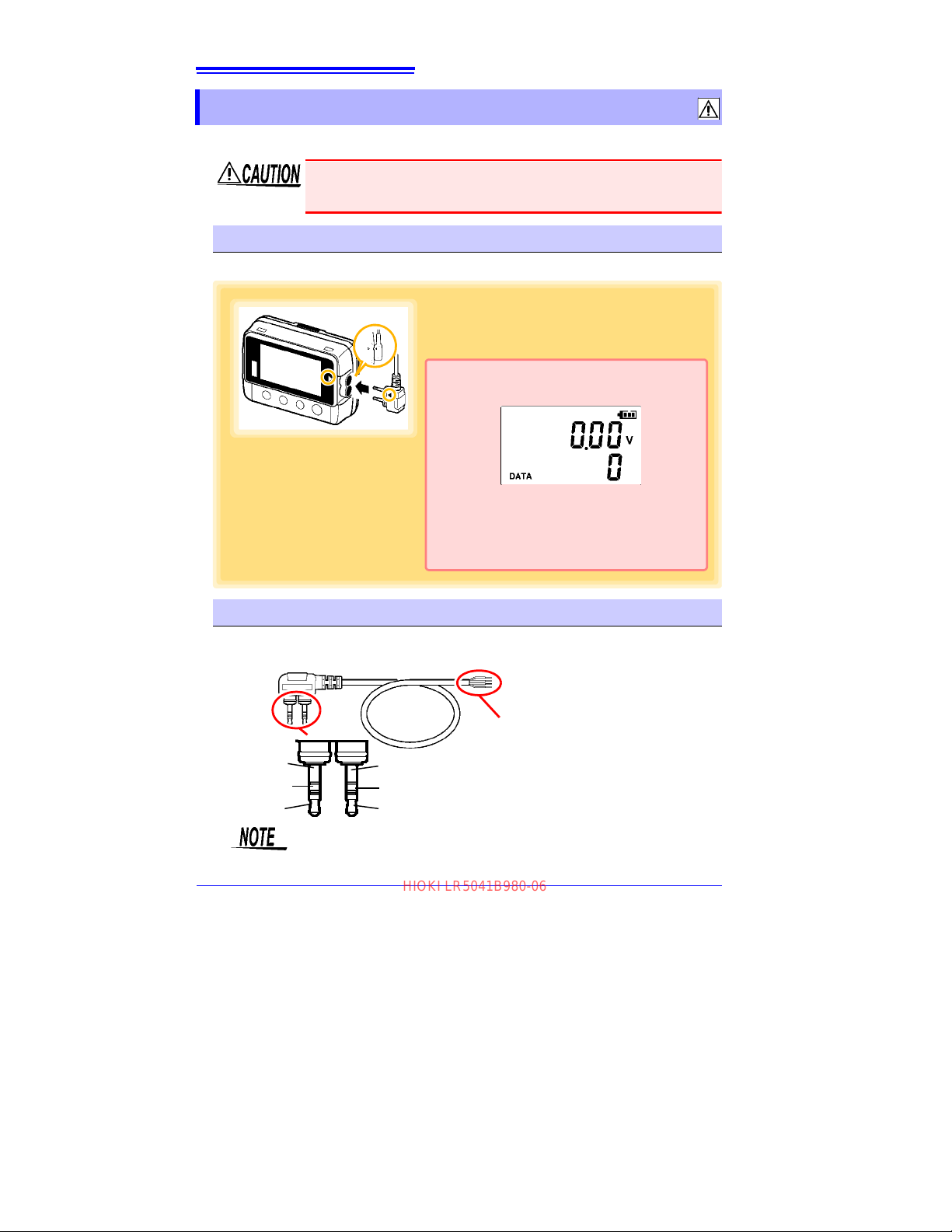
Align the triangles on the plug body and in front of
the connection cable jacks, and insert the plug
securely.
Correct values are not displayed unless the plug is
inserted all the way in.
If values are not displayed correctly even when the
plug is inserted properly, the logger or cable may
be damaged. Repair may be necessary.
See: "Requesting repairs" (p.91)
(LR5043 Example)
Voltage Input (-)
Preheat Signal
Cable length: Approx. 1000 mm
Red Wire: Voltage Input (+)
Black Wire: Voltage Input (-)
Yellow Wire: Preheat Signal
White Wire: Preheat Ground
Preheat
Ground
Unused
Voltage Input (+)
Unused
HIOKI LR5041B980-06
2.2 Connecting a Connection Cable
2.2 Connecting a Connection Cable
Connect a connection cable to the logger's connection cable jacks.
• To avoid breaking the cable, do not bend or pull it.
• Avoid stepping on or pinching cables, which could damage the cable
insulation.
Connection Method
Required Items: Hioki LR9802 Connection Cable
Connection Cable
LR9802 Connection Cable
When the preheat signal is not used, insulate the preheat signal wire
(yellow) and the preheat ground wire (white) with a insulating tape not to
touch mistakenly each other.
Find Quality Products Online at: [email protected]
www.GlobalTestSupply.com
Page 25
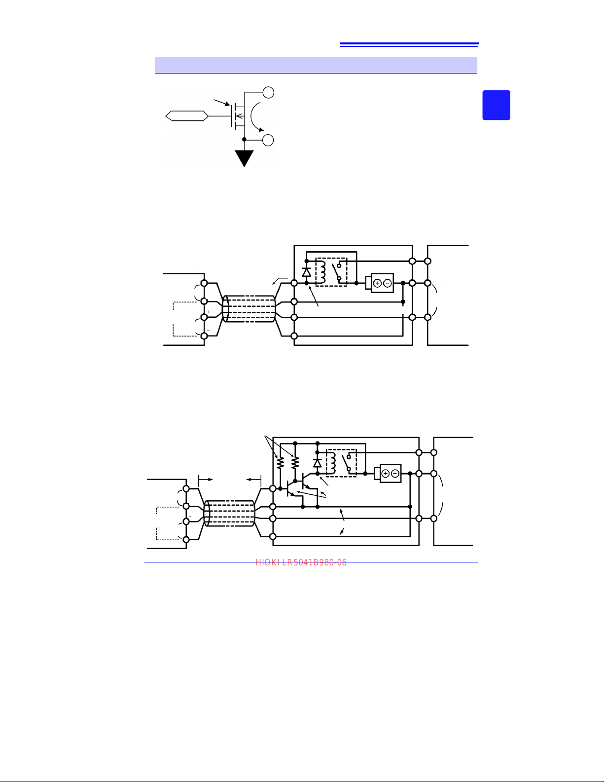
About the Preheat Signal
Open-Drain Output
∗
Max. Rating: 30 V @50 mA
(Allowable Power Dissipation: 200 mW)
GND
FET
Current Flow Direction
Preheat Signal
Logger
Preheat
Sensor
Preheat Connection Circuit
Current i
LR9802 Connection Cable
Relay
Back-emf Protection Diode
Power In
GND
Voltage
output
Power supply
GND
Signal
Signal
Voltage
input
Common
Logger
Sensor
Preheat Connection Circuit
Relay
Back-emf Protection Diode
Power In
GND
Relay Switching Transistors
Wire as
short as
possible
10 kΩ Pull-Up Resistors
Power supply
Voltage
output
Signal
Wire as short as possible
LR9802 Connection Cable
Preheat
GND
Signal
Voltage
input
Common
HIOKI LR5041B980-06
Internal Preheat Signal Circuit
21
2.2 Connecting a Connection Cable
2
Chapter 2 Measurement Preparations
* The FET switch between the preheat signal and ground is turned on during preheating.
Connect to allow preheat signal current flow to ground.
Preheat Signal Connection Circuit Example
The preheat signal switches power to the sensor on and off. Connect the logger, sensor, power supply, and re
lay as shown below.
< Typical Circuit >
< When Sensor Output Volta
ge Is Low >
In the above circuit, if relay current (i) is large and sensor output voltage is low, measurement values may be affected by current flow in the connection cable. The amplitude of the effect is determined by cable resistance (about 0.2Ω) and relay current (i).
For example, if the relay current is 10 mA, the effect is 10 mA × 0.2 Ω=2 mV. When
the sensor output voltage is low, this 2 mV results in erroneous measurements. In
such cases, the effect can be minimized using the circuit on the next page.
3
Find Quality Products Online at: [email protected]
www.GlobalTestSupply.com
Page 26
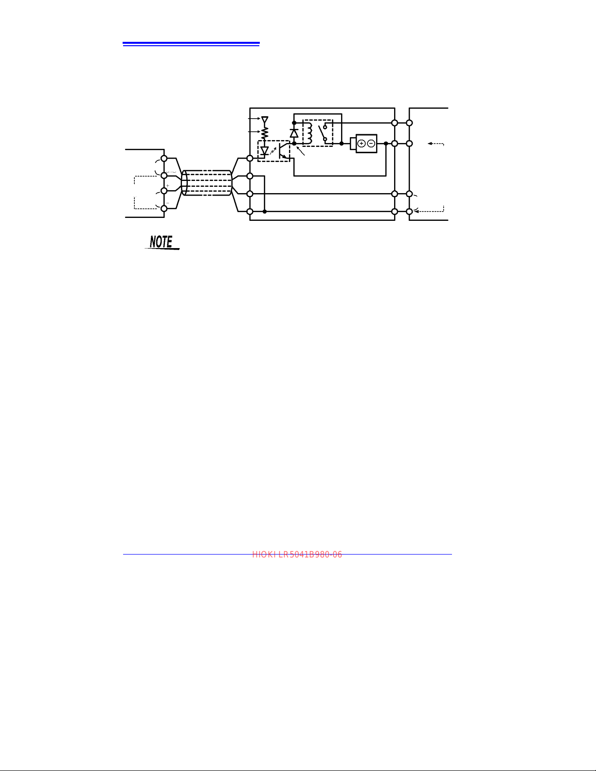
22
Logger
Preheat Connection Circuit
Relay
Back-emf Protection Diode
Sensor
Power In
GND
Power supply
Separate Power Supply
Current-Limiting Resistor
Photocoupler
GND
Voltage
output
Signal
GND
Signal
LR9802 Connection Cable
Preheat
Voltage
input
Potential Difference
Common
HIOKI LR5041B980-06
2.2 Connecting a Connection Cable
< Isolating the Preheat Signal >
If the ground side of the power supply cannot be connected to measurement signal
ground, isolate the preheat signal as shown in the following circuit diagram. However,
in this case, a separate photocoupler power supply is required.
• When connecting a relay, transistors, and a photocoupler to the preheat signal line, be sure that the connected supply voltage and drive
current do not exceed the maximum preheat signal ratings (30 V, 50
mA).
• When using a relay, be sure to include a back-emf protection diode to
prevent damage from counter-emf when relay coil power is removed.
Find Quality Products Online at: [email protected]
www.GlobalTestSupply.com
Page 27
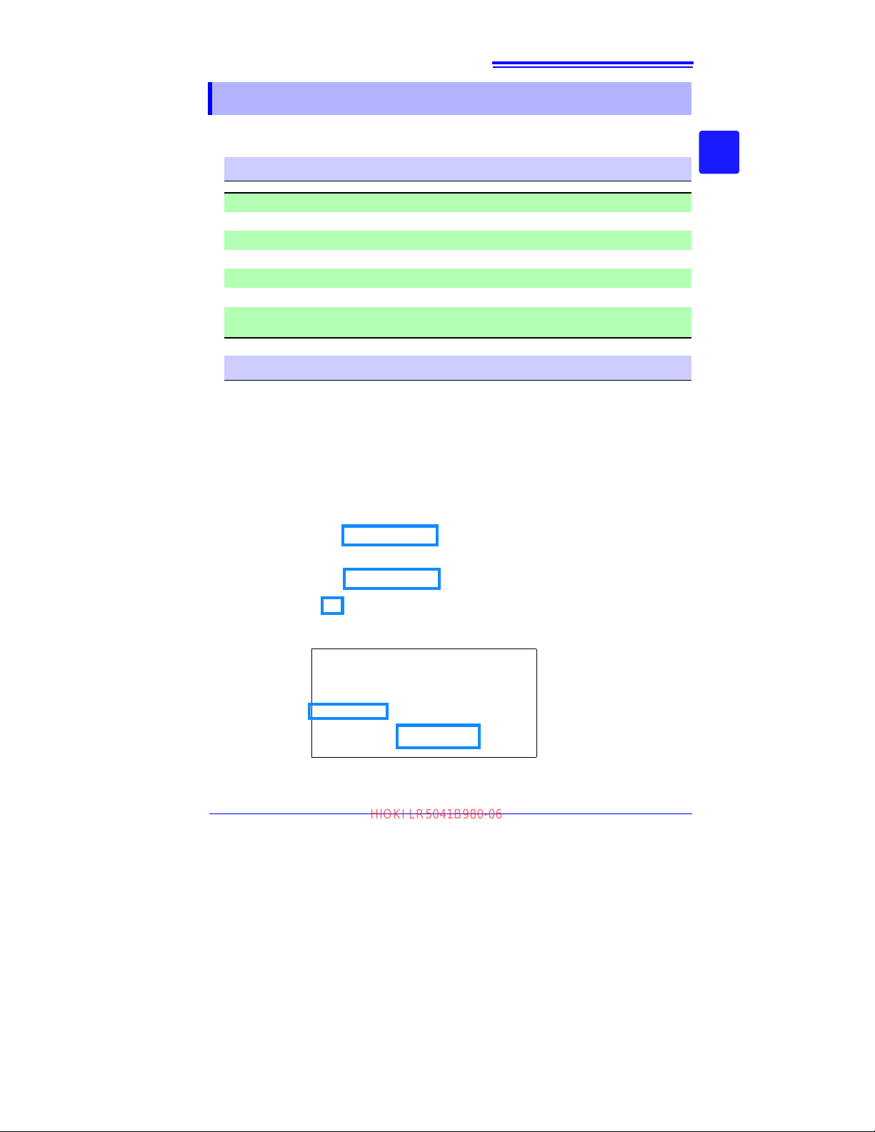
23
1
2
3
1
2
HIOKI LR5041B980-06
2.3 Installing the PC Application Program
2.3 Installing the PC Application Program
To save, browse, or print data, or to make logger settings from a computer, first
install the "LR5000 Utility Program".
LR5000 Utility Program Operating Requirements
CPU 1 GHz or faster processor clock
RAM 1 GB or more (32-bit), 2 GB or more (64-bit)
OS Windows 7 or Windows 10
Library .NET Framework 4.5.2 or later
Interface USB
Monitor Resolution 1024×768 or higher
Hard Disk
Installation Procedure
At least 30 MB free space
(Additional space is required for storing recorded data.)
1. Start the computer.
Administrator authority may be required for the installation.
2. Set the included CD to the CD-ROM drive.
2
Chapter 2 Measurement Preparations
3
3. Click [Start] to display the application list.
Click [Windows System] - [File
Explorer] to start Explorer.
4. Click [This PC], and then, double-click [CD Drive (D)] drive.
Find Quality Products Online at: [email protected]
www.GlobalTestSupply.com
Page 28
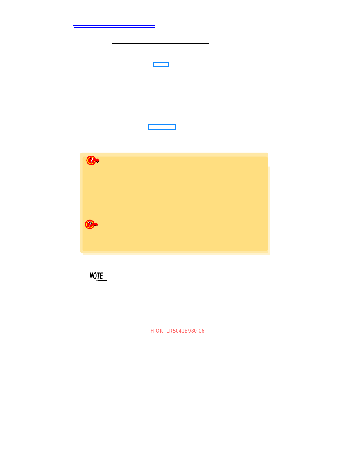
24
(The extension may not be displayed.) After the installer
starts, follow the instruction to
proceed with the installation.
(The extension may not be displayed.) After the installer
starts, follow the instruction to
proceed with the installation.
If the computer fails in the installation
Some computers, depending on system environments including OS and securi ty,
can fail in the installation using the CD-R.
In such a case, download the executable program from the “Drivers, Firmware,
Software” page of Hioki’s website, and then install it again.
The data logger series LR5000 programs consists of LR5000 Utility Program and
LR5091/LR5092 Device Driver, both of which need to be installed.
If the earlier version of LR5091/LR5092 Device Driver has been insta lled, uninstall it before installing the latest version of program.
Ask your system administrator if installing application programs or changing system environments is prohibited for security reasons.
How to start the program?
The program starts automatically from the next Windows logon. (The icon
appears in the task tray (notification area) (p.36).)
Click the icon and click [Show Main Screen].
HIOKI LR5041B980-06
2.3 Installing the PC Application Program
5. Double-click the [english] folder.
6. Double-click [setup.exe] (SET UP file).
For setting and importing recorded data from loggers other than the
LR5000 series, use the Communication Utility program supplied with
the model 3911 or 3912 Communication Base. You can browse the
recorded data by using LR5000 Utility Program also.
Find Quality Products Online at: [email protected]
www.GlobalTestSupply.com
Page 29
Settings and recorded data are not deleted when uninstalling or upgrad-
1
Click [Start]-[Settings].
(The
[Windows Settings] dialog box appears.)
2
Click [Apps].
(The [Apps & features] screen appears.)
3
Select the [LR5000 Utility Program], and click the [Uninstall] button.
4
Click [Uninstall].
(The program is uninstalled.)
3
2
4
Follow the procedure on the download page to install the latest version.
(The old version is uninstalled automatically.)
HIOKI LR5041B980-06
ing the program.
Uninstall Procedure
25
2.3 Installing the PC Application Program
Follow this procedure to uninstall the LR5000 Utility Program.
2
Chapter 2 Measurement Preparations
3
Version Upgrading
Download the latest version of the LR5000 Utility Program from our website
Find Quality Products Online at: [email protected]
www.GlobalTestSupply.com
Page 30
26
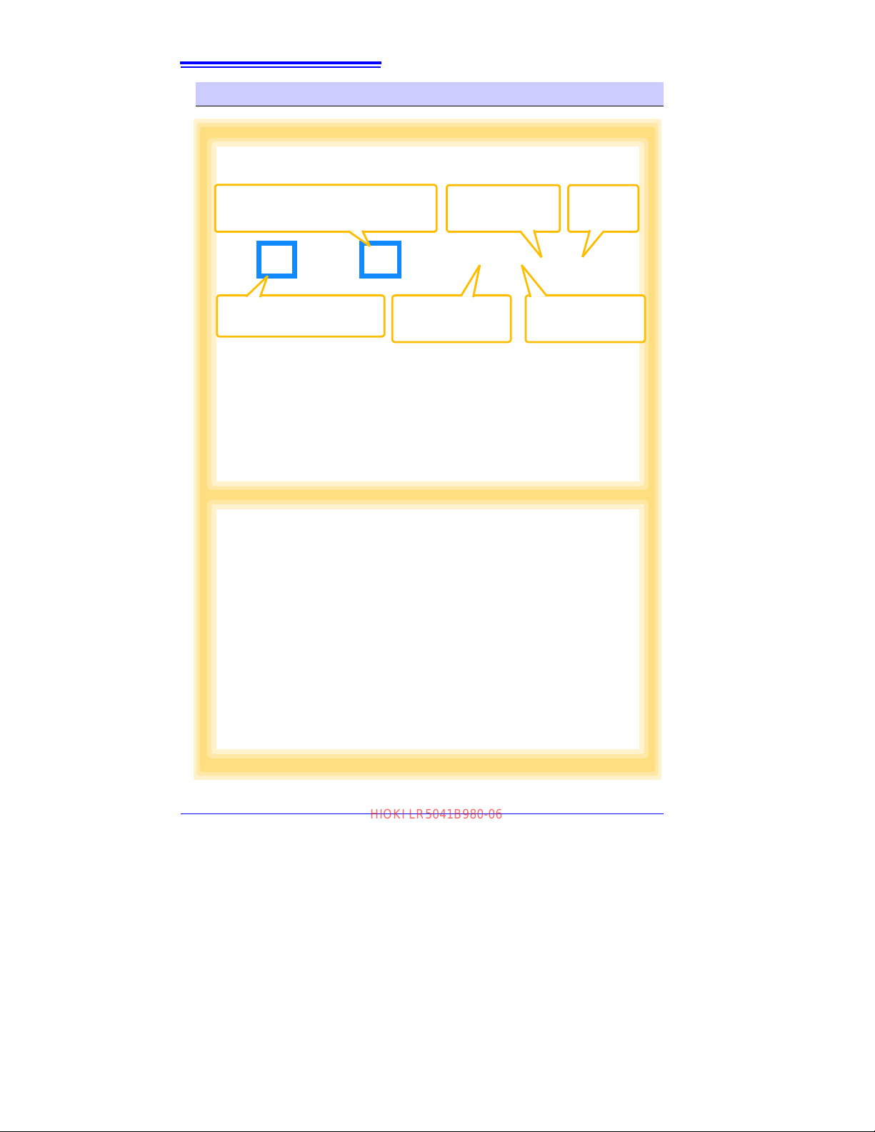
Main Screen (p.36)
Displays Setting Screens:
Logger settings
Displays the data import screens:
Logger data import
Display Data
Viewing screens
Display Data
Sorting screens
Displays Option
screens
Displays
Help.
Setting Screens (p.37)
Make and export logger settings.
Example: Logger settings
HIOKI LR5041B980-06
2.3 Installing the PC Application Program
LR5000 Utility Program Screens
Find Quality Products Online at: [email protected]
www.GlobalTestSupply.com
Page 31

27
Data Viewing Screens (p.62)
View imported data on these screens.
Select a file to view, as a graph or table.
Example: Screens for viewing the latest data
Data Import Screens (p.59)
Import data from the logger with these screens.
Example: Logger import screen
HIOKI LR5041B980-06
2.3 Installing the PC Application Program
2
Chapter 2 Measurement Preparations
3
Find Quality Products Online at: [email protected]
www.GlobalTestSupply.com
Page 32

28
Option Screens (p.81)
Make advanced settings on these screens.
You can specify the data importing method.
Example: Import Method Setting screen
Data Sorting Screens (p.75)
Sort imported data on these screens.
You can copy, delete, move, combine, and extract data.
Example: Data Copy screen
HIOKI LR5041B980-06
2.3 Installing the PC Application Program
Find Quality Products Online at: [email protected]
www.GlobalTestSupply.com
Page 33
29
HIOKI LR5041B980-06
3.1 Settings List
Settings Chapter 3
Configure measurement settings before starting to record.
Logger settings can also be made from a PC running the LR5000 Utility Program.
(p.36)
3.1 Settings List
Following is a list of all settings.
Although all settings are available from the LR5000 Utility Program, some settings
are limited when made from the logger.
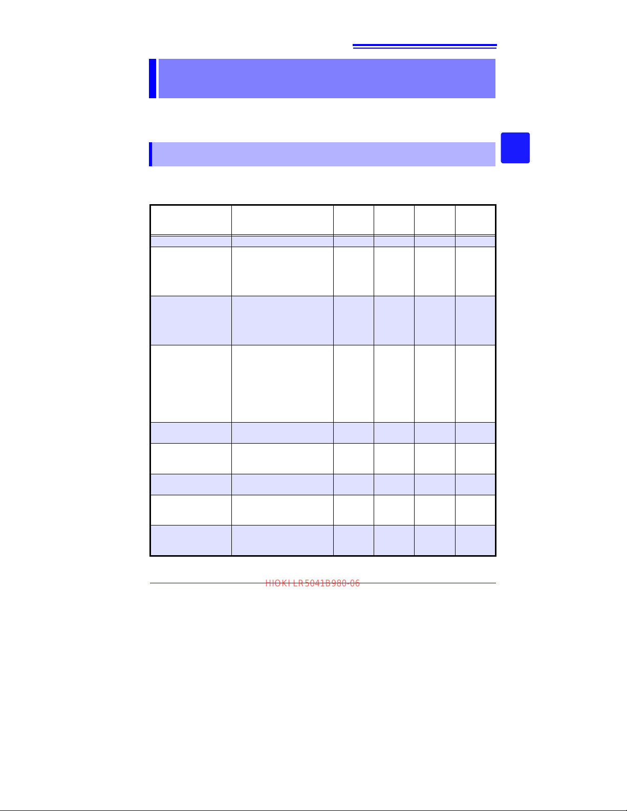
LR5000
Setting Item Setting Options Logger Refer To
Recording Interval Sets the recording interval. Yes (p.31) Yes (p.39)
Current Date and
Time
Stop Method
Recording Mode
Power Save
Preheat Time
Model Comment
Channel Comment
Recording Start
Method
Set the curren
day
, hour, a
LR5000 Utility Program can
set the logger's clock to
match the computer’s.)
Select the processing
method when memory
becomes full.
Selects instantaneous or
statistical value recording
(measurements are ta
once per second, and
instantaneous, maximum,
mi
nimum, and a
ues are saved at each
recordin
Battery life is extended
when on (enabled).
Select the ON time for
exte
rnal sensor
trol.
Enter a comment for the
specified logger.
Enter a comment for the
specified me
channel.
Select the recording start
method. (The start time can
be specified.)
t year, month,
nd minute. (The
verage val-
g interval).
power con-
asurement
Yes (p.32) Yes (p.42)
Yes (p.33) Yes
ken
Yes (p.34) Yes (p.39)
Yes (p.34) Yes (p.38)
Yes (p.35) Yes (p.40)
No - Yes (p.38)
No - Yes (p.38)
No - Yes (p.39)
Utilit
Pr
y
ogram
Refer To
Included
in the
recording
stop
method
3
Chapter 3 Settings
3
Find Quality Products Online at: [email protected]
www.GlobalTestSupply.com
Page 34
30
HIOKI LR5041B980-06
3.1 Settings List
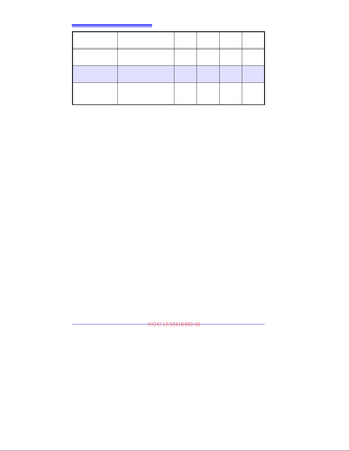
Setting Item Setting Options Logger Refer To
Recording Stop
Method
Scaling
Alarm Thresholds
Select the recording stop
method. (The stop ti
be specified.)
Use to scale measured values to display as adjusted
values.
Set upper and lower threshold values to display the
alarm indicator [AL] on the
logger.
me can
No - Yes (p.39)
No - Yes (p.40)
No - Yes (p.41)
LR5000
Utility
Program
Refer To
Find Quality Products Online at: [email protected]
www.GlobalTestSupply.com
Page 35
31
1
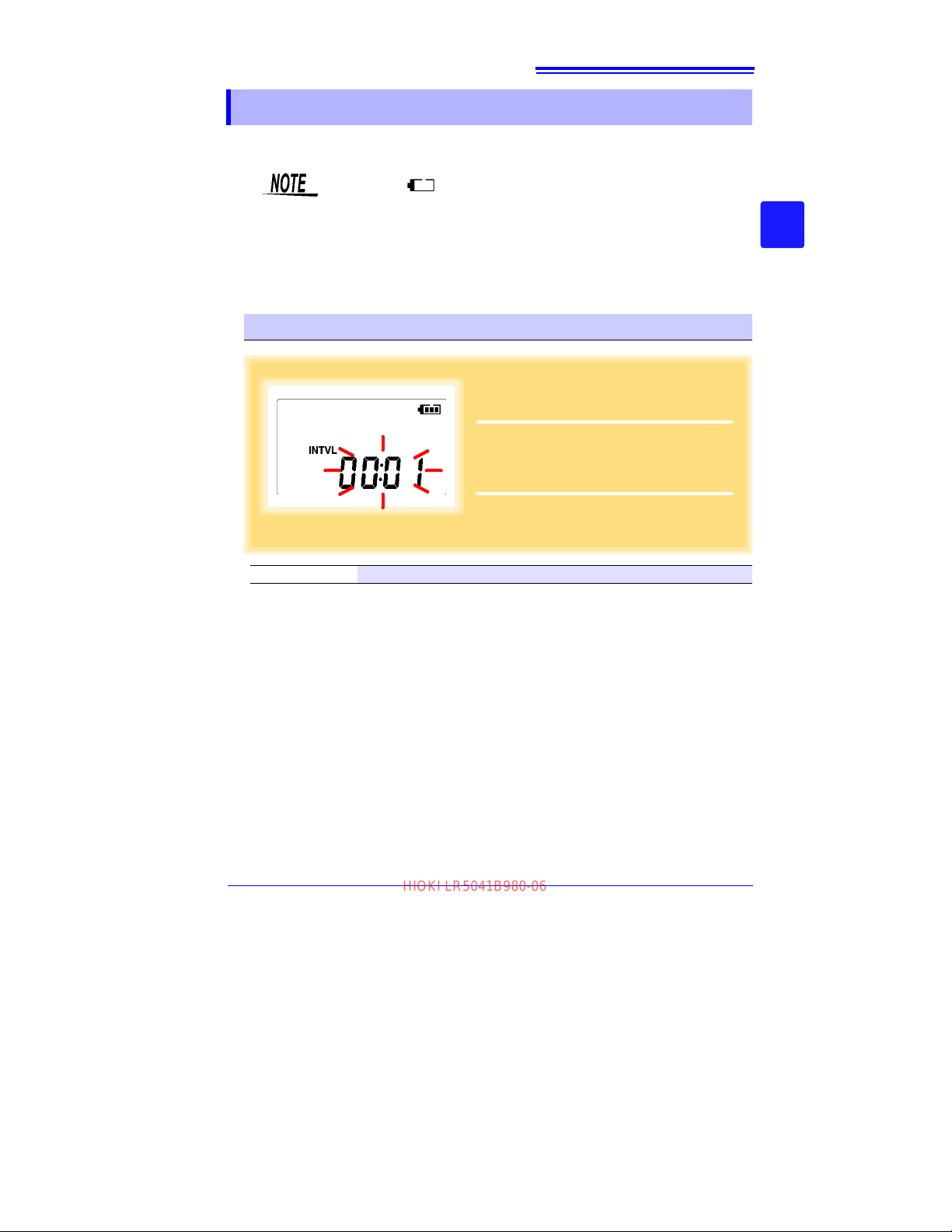
Press the SET button to display the interval setting.
(The [INTVL] indicator appears,
and the setting blinks.)
2
Press the (+) and (-) buttons to change
the recording interval.
Example of configuration:
1sec 00:01, 1 minute 01:00
3
Press the SET button to accept the setting.
(The year setting is displayed.)
HIOKI LR5041B980-06
3.2 Making Settings on the Logger
3.2 Making Settings on the Logger
To return to the Measurement display from any Settings display, press the REC/
STOP button.
• When the battery indicator appears, settings cannot be changed
(although they can still be displayed).
• When no operation occurs for 30 seconds with Settings displayed,
automatically switches to Measurement display.
• Settings cannot be changed while recording. However, settings can
still be displayed by pressing the SET button from the Measurement
display.
Recording Interval Setting
3
Chapter 3 Settings
3
Recording Interval 1(Default)/2/5/10/15/20/30 sec., 1/2 /5/10/15/20/30/60 min
Find Quality Products Online at: [email protected]
www.GlobalTestSupply.com
Page 36
32
1
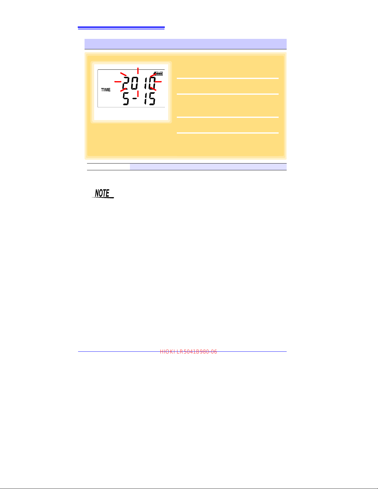
Press the SET button to display the time
settings.
([TIME] is displayed, and the year
setting blinks.)
2
Press the (+) and (-) buttons to change
the year.
3
Press the SET button to accept the year
setting.
(The month setting starts blinking.)
4
Repeat this procedure to set the month,
day, hour, and minute.
5
Press the SET button to accept the setting.
(The stop method setting is displayed.)
Year Setting display
HIOKI LR5041B980-06
3.2 Making Settings on the Logger
Real-Time Clock Setting
Setting Range 01/01/2010, 00:00 to 12/31/2039, 23:59
Note: Seconds are not settable. However, seconds are set to zero at the inst
away from the minute setting.
After the battery has been removed for a long time, or if the clock is
incorrect, reset it.
ant the display is switched
Find Quality Products Online at: [email protected]
www.GlobalTestSupply.com
Page 37
3.2 Making Settings on the Logger
1
Press the SET button to display the stop
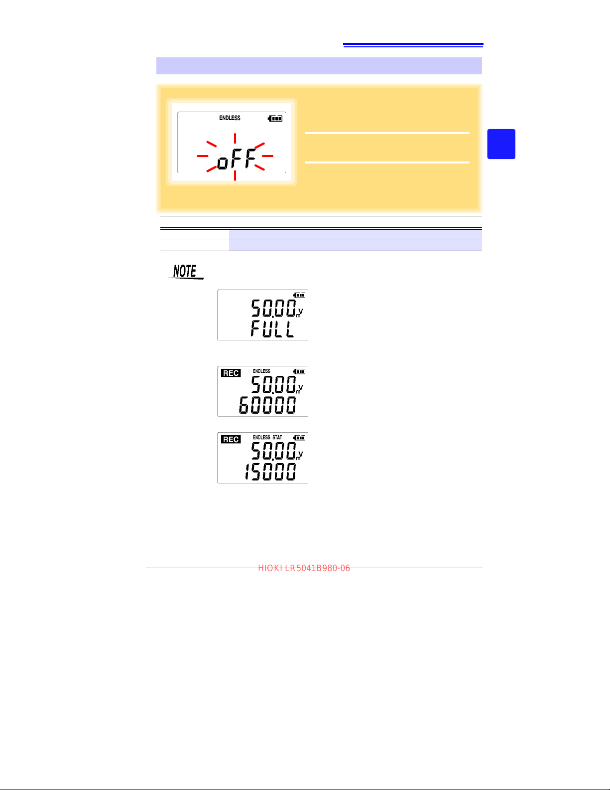
method setting.
(The [ENDLESS] indicator
appears, and the setting blinks.)
2
Press the (+) and (-) buttons to select
[ON] or [OFF].
3
Press the SET button to accept the setting.
(The recording mode setting is displayed.)
(the Measurement display shows channel measurement value and recorded data count)
(instantaneous value recording display)
(statistical value recording display)
HIOKI LR5041B980-06
Stop Method Setting (for when memory becomes full)
33
3
Chapter 3 Settings
3
Setting Options
OFF Recording stops when memory becomes full (One-Time Recording).
ON(Default) The oldest data is overwritten when memory is full (Endless Recording).
Description
When memory becomes full during one-time recording, the recorded
data count appears as follows.
When memory becomes full during endless recording, the recorded
data count (equal to the memory capacity) remains constant.
Find Quality Products Online at: [email protected]
www.GlobalTestSupply.com
Page 38
34
1
Press the SET button to display the
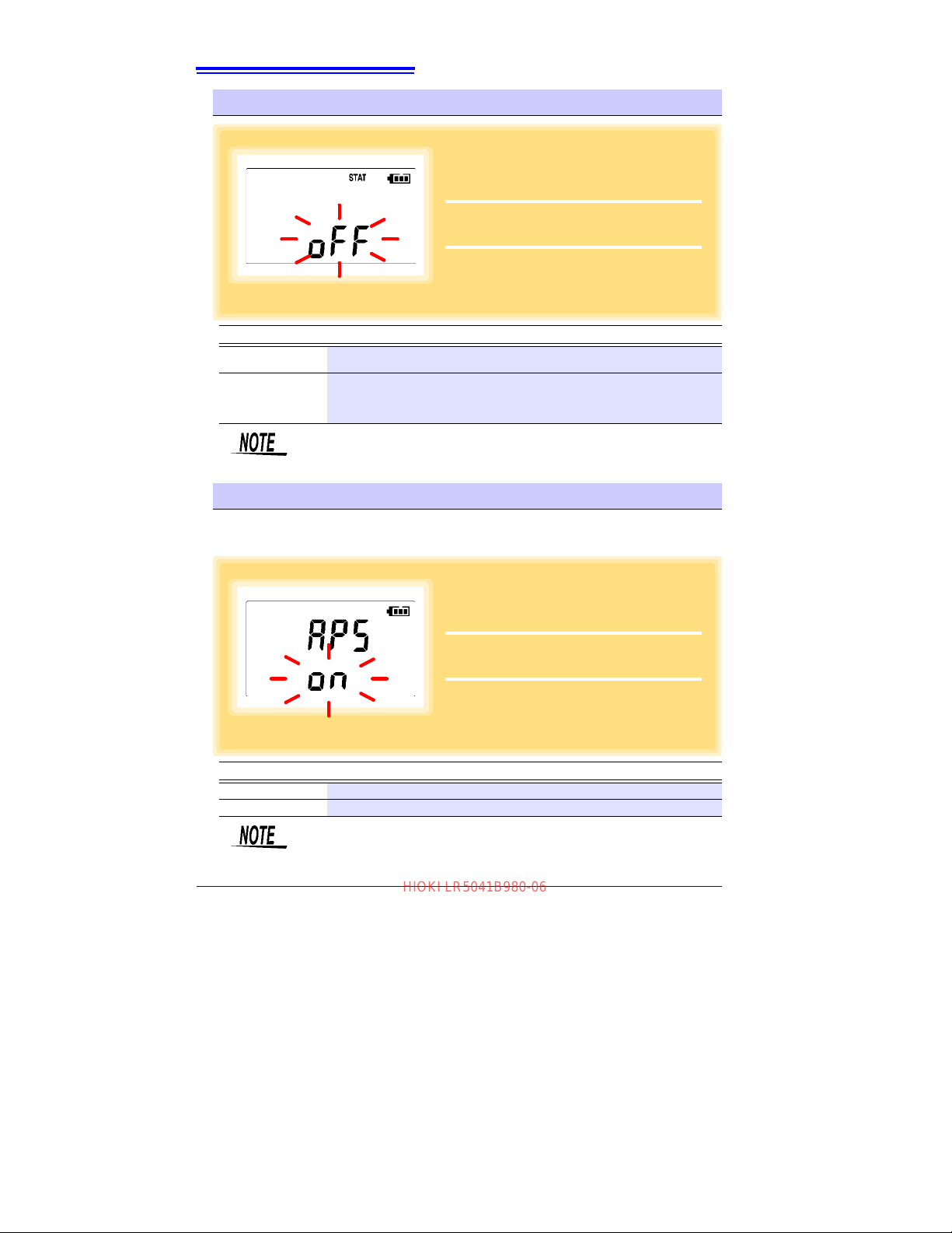
recording mode setting.
(The [STAT] indica-
tor appears, and the setting blinks.)
2
Press the (+) and (-) buttons to select
[ON] or [OFF].
3
Press the SET button to accept the setting.
(The power save setting is displayed.)
1
Press the SET button to display the
power save setting
([APS] appears, and the
setting blinks).
2
Press the (+) and (-) buttons to select
[ON] or [OFF].
3
Press the SET button to accept the setting.
(The measurement display appears.)
HIOKI LR5041B980-06
3.2 Making Settings on the Logger
Recording Mode Setting
Setting Options
OFF (Default)
ON
Description
The instantaneous value is recorded at each recording interval (instantaneous
recording).
When on, measurements are taken once per second, and instantaneous, maximum, minimum, and average values are recorded at each recording inte
tistical recording).
(Up to 15,000 data values can be recorded.)
Statistical recording cannot be selected when the recording interval is
set to one second.
rval. (sta-
Power Save Setting
The power save function turns off the display 30 seconds after the last button is
pressed. The display reappears upon the next button press.
Setting Options
ON (Default) Power save is enabled.
OFF Power save is disabled (the display remains visible).
Description
The Auto Power Save feature consumes a small amount of current
See: "Appendix 3 Batte ry Li fe Approximation" (p.A2)
Find Quality Products Online at: [email protected]
www.GlobalTestSupply.com
Page 39
3.2 Making Settings on the Logger
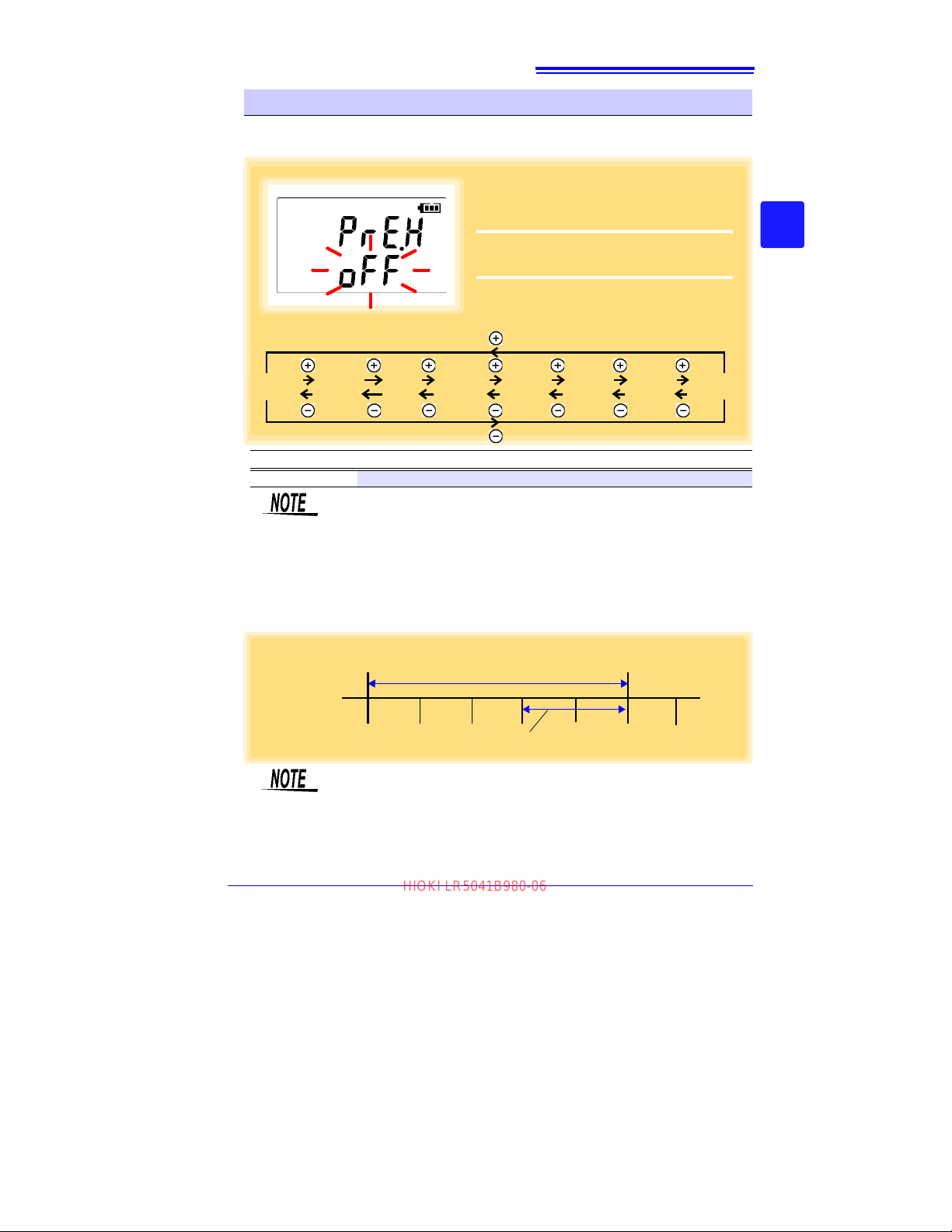
1
Press the SET button to display the preheat time setting.
(The display indicates
“PrE.H”.)
2
Press the (+) and (-) buttons to change
the preheat time.
3
Press the SET button to accept the setting.
(The measurement display appears.)
PrE.H
OFF
PrE.H
0.5
PrE.H
2
PrE.H5PrE.H10PrE.H30PrE.H
60
PrE.H
1
The display changes as follows.
Recording Interval (5 sec.)
Measurement ([REC]
indicates recording)
Hold the REC/STOP
button for two seconds
Preheat time (2 sec.)
HIOKI LR5041B980-06
Setting the Preheat Time
The preheat function provides an output signal synchronized to the logger's measurement timing, to control power supplied to each sensor.
35
3
Chapter 3 Settings
3
Setting Options
Preheat Time OFF(Default)/0. 5 /1/2/5/10/30/60 sec.
Preheat Signal Output Timing (when Preheat is enabled)
1. Du
ring measurement display: The Preheat signal is output continuously.
2. When a measurement is not displayed: Measurement (recording) occurs after the
specified preheat time.
Description
The preheat time cannot be set longer than the recording interval. It
must be set shorter than the recording interval (longer preheat times are
not available). Also, if the recording interval is set shorter than the preheat time setting, the preheat setting is automatically changed to [OFF].
• When power save is enabled and a button is pressed to display the
measured value, some time may be required for the measured value
to stabilize, according to the response time (from power-up to stable
output) of the sensor.
• When the preheat time setting is not OFF, and during statistical value
recording, the preheat signal is output continuously.
Find Quality Products Online at: [email protected]
www.GlobalTestSupply.com
Page 40
36
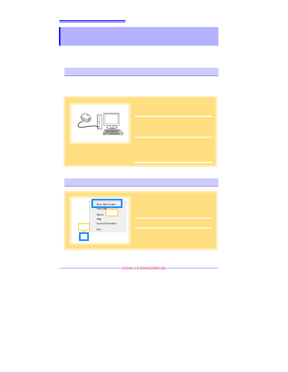
1
Plug the USB cable into the USB port on
the LR5091 (or LR5092-20), and into a
USB port on the computer.
2
Dock the logger in the LR5091 (or LR5092-
20).
(When docking, be sure that the infrared ports
are aligned.)
The main display appears automatically (by
default).
When the logger contains recorded data, the
import confirmation dialog appears.
Click [Yes] to import the data automatically.
(p.49)
1
2
1
If the main screen is not displayed on the
computer, click the icon in the task tray
(notification area), and click [Show Main
Screen].
The main screen appears.
1
Click
Click
HIOKI LR5041B980-06
3.3 Making Settings from the LR5000 Utility Program
3.3 Making Settings from the LR5000 Utility
Program
Logger settings can be made with the LR5000 Utility Program supplied with the
LR5091 Communication Adapter and the LR5092-20 Data Collector.
Install the LR5000 Utility Program on the computer before connecting. (p.23)
Connecting the Logger, LR5091, and Computer
Connect to the computer using the supplied USB cable.
Required Items
: Logger, LR5091 Communication Adapter, USB cable, Computer
Logger Settings
Find Quality Products Online at: [email protected]
www.GlobalTestSupply.com
Page 41
37
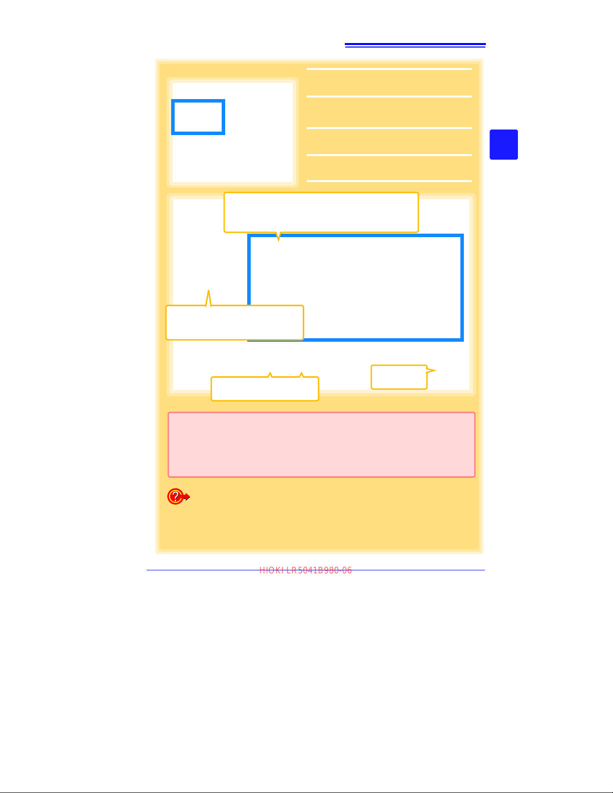
2
For the [Setting], click the [Logger] button.
The Logger Settings screen appears.
(If the logger is not connected, you are
prompted to connect it. Connect the logger.)
3
Select the logger from the device list*,
and edit the settings. (p.38)
4
Click the [Send Settings] button.
4
How can current settings be imported from the connected logger?
1. Click the [Import Settings] button at the upper right of screen.
(A dialog appears.)
2. Click the [Import Settings to Computer] button. (The logger's settings
are now reflected in the program.)
2
Click to select.
The currently selected logger's background is a different color.
3
Setting Options
Note: The displayed settings are those previously made
from the LR5000 Utility Program, which may be different from the current settings within the logger itself.
* About the Device List
• Up to ten loggers can be displayed when connected to the computer.
• When [Show disconnected loggers ] is sele cte d, discon nected logge rs that had settings previously saved appear in the list.
• The list can be sorted in ascending order ([Sort List]).
Returns to the
main screen.
Settings from other loggers can
be applied. (p.38)
HIOKI LR5041B980-06
3.3 Making Settings from the LR5000 Utility Program
3
Chapter 3 Settings
3
Find Quality Products Online at: [email protected]
www.GlobalTestSupply.com
Page 42
38
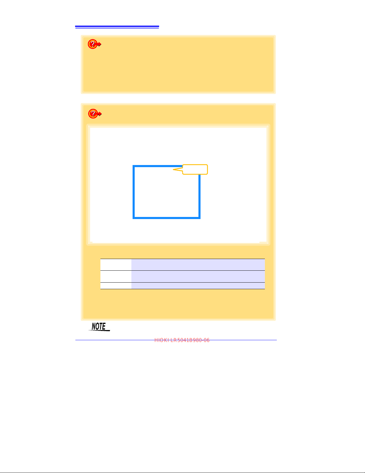
How can the settings from one logger be copied to another?
1. From the device list, select a logger with settings to be copied, and click
the [Copy Settings] button.
2. From the device list, select a logger as the destination for the settings,
and click the [Paste Settings] button. (A dialog appears.)
3. Click the [Paste] button in the dialog box. (The settings are copied.)
How can I learn more about changing settings?
1 Setting the [Basic Settings].
2 Settings on the [Recording Method] tab.
Model
comment
Enter a comment to describe the logger as needed.
Power save
setting
Enable or disable the power save setting (p. 30).
See:
"Appendix 3 Battery Life Approximation" (p.A2)
CH1 comment Enter a comment to describe the measurement channel as needed.
Note: Comments may consist of up to 2
0 characters.
The following characters are not allowed: \, /, :, *, ?, ", <, >, and |.
1
2
Click a tab.
HIOKI LR5041B980-06
3.3 Making Settings from the LR5000 Utility Program
The Auto Power Save feature consumes a small amount of current
Find Quality Products Online at: [email protected]
www.GlobalTestSupply.com
Page 43
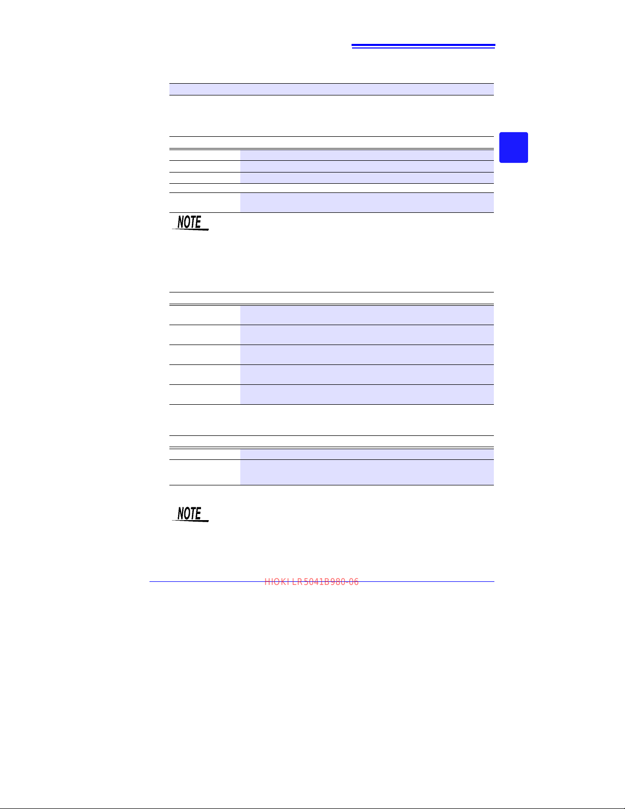
39
HIOKI LR5041B980-06
3.3 Making Settings from the LR5000 Utility Program
Rec interval
Sets the recording interval.
1/2/5/10/15/20/30 sec., 1/2 /5/10/15/20/30/60 min
Start Method
Select the recording start method.
When [Scheduled Time] is selected, specify the start date and time.
Setting Options
Button Operation Starts recording by pressing the button on the logger.
Start After Sent Starts recording by pressing the [Send Settings] button.
Scheduled Time Starts recording at the scheduled time a fter pressing the [Send Settings] button.
Valid setting time
range
Stop Method
Select the recording stop method.
When [Scheduled Time (Endless)] or [Scheduled Time (One- Time)] is selected,
the date and time need to be set.
Setting Options
Button Operation
(endless)
Button Operation
(one-time)
Scheduled Time
(Endless)
Scheduled Time
(One-Time)
Hold Data at
Scheduled Time
Rec Mode
Select the recording mode.
Setting Options
Instantaneous The instantaneous value is recorded at each recording interval.
Statistical
See: Statistical recording results in shorter battery life. "Appendix 3 Battery Life Approxima-
tion" (p.A2)
Description
01/01/2010, 00:00 to 12/31/2039, 23:59
When the [Scheduled Time] start method is enabled, the [REC] indicator on the logger display blinks until the specified start time.
Description
Stops recording by pressing the button on the logger.
The oldest data is overwritten when memory is full.
Stops recording by pressing the button on the logger.
Recording also stops when memory becomes full.
Stops recording at the scheduled time.
The oldest data is overwritten when memory is full.
Stops recording at the scheduled time.
Recording also stops when memory becomes full.
Specify when setting [Scheduled Time (Endless)].
Select this check box to record the data at the scheduled time and stop recording.
Description
Measurements are taken once per second, and instantaneous, maximum, minimum, and average values are recorded at each recording interval. (Up to
15,000 data
values can be recorded.)
Statistical recording cannot be selected when the recording interval is
set to one second.
3
Chapter 3 Settings
3
Find Quality Products Online at: [email protected]
www.GlobalTestSupply.com
Page 44
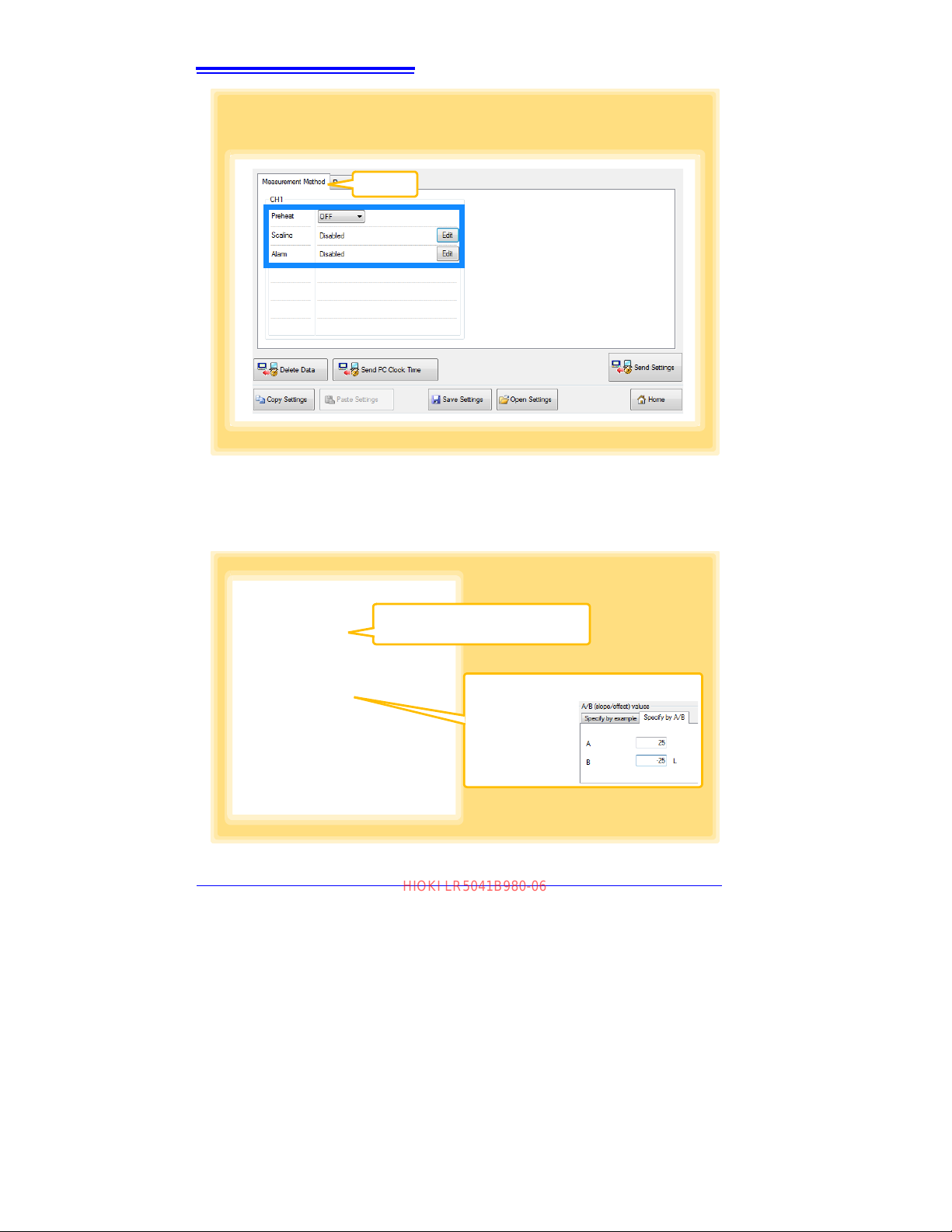
40
Preheat time setting contents
See: "Setting the Preheat Time"
(p.35)
Click a tab.
3 Settings on the [Measurement Method] tab
Click the [Edit] button to display the setting dialog box.
3
See: "What is Scaling?" (p.42)
Enable scaling
Select this check box to enable scaling.
Clicking this tab
changes the setting
options. Make settings on either tab.
(The settings are applied to the other tab.)
Specify by example, or Specify by A/B
HIOKI LR5041B980-06
3.3 Making Settings from the LR5000 Utility Program
Scaling (set as needed)
The following scaling calculation is applied to measured values.
Scaled Result = Raw data (measured value) × A + B × SI prefix (multiplier)
The scaled result is displayed on the logger.
Find Quality Products Online at: [email protected]
www.GlobalTestSupply.com
Page 45
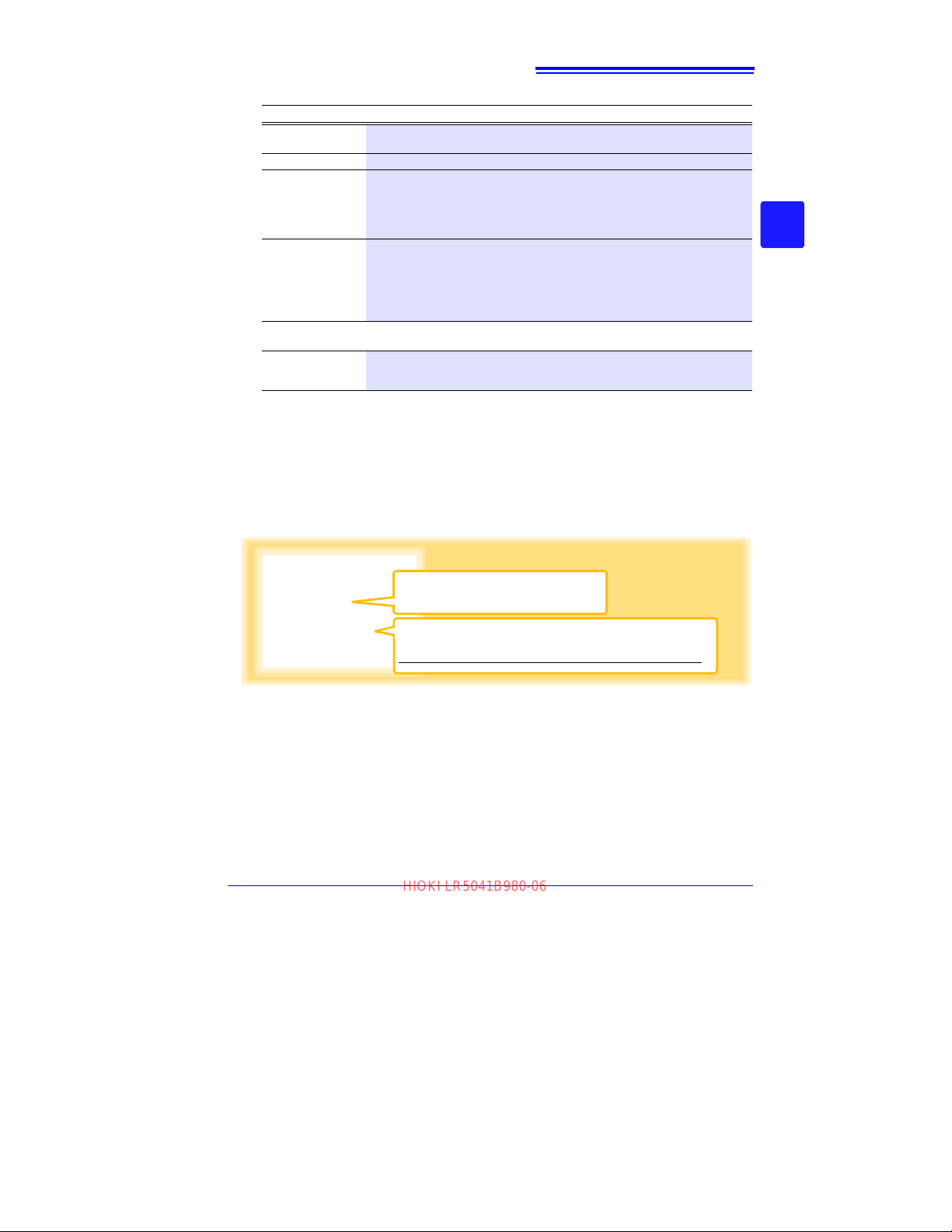
3.3 Making Settings from the LR5000 Utility Program
Upper and lower thresholds
Enter numerical values between -9999 and 9999 (up to six digits).
When scaling is enabled, enter these values as scaled results.
Enable alarm judgment function
Select this check box to enable the alarm.
HIOKI LR5041B980-06
1. Set the following options.
Setting Options
Specify by
example
Specify by A/B Enter the scaling coefficients (A and B, up to ten digits each).
Scaled units
Display digits
Description
Enter two known conversion points (up to ten digits each).
• Select the [SI Prefix].
([p]=1E-12, [n]=1
[G]=1E9, [T]=1E12)
• Enter the [Char.
(Up to five characters, except \, /, :, *, ?, ", <, >, and |.)
•Select [Fixed decimal point] and specify the [Decimal digits] to be dis-
played to the right of the decimal point. Valid settings are 0 to 3.
(Examples: selecting 0 displays values in the form 0000, and selecting 3 displays values in the form 0.000)
• When [Fixed decimal point] is not
its (0.000 to ±9999) with aut
E-9, [μ]=1E-6, [m]=1E-3, blank =1E0, [k]=1E3, [M]=1E6,
String] to identify the scaled units.
selected, values are displayed as four dig-
omatic decimal positioning.
2. Confirm settings.
Setting
confirmation
Confirm that scaling is performed properly.
Enter any numerical value as raw data, and click the [Calc] button
scaled result.
to display the
3. Click the [Save] button.
caling settings are saved, and the display returns to the Logger Settings screen.)
(S
Note: If you click the [Cancel] button without saving the settings, the display still returns to
the Logger Settings screen.
41
3
Chapter 3 Settings
3
Alarm Thresholds (set as needed)
Set the upper and lower alarm threshold values. When a measurement is outside of
the specified area, the [AL] (alarm) indicator is displayed on the logger.
Click the [Save] button to save y
our settings.
(The display returns to the Logger Settings screen.)
Note: If you click the [Cancel] button without saving the settings, the display still returns to the
Logger Settings screen.
Note: Alarm judgment is performed at every recording interval during instantaneous recording,
and once per second during statistical recording.
Note: Alarm judgment is performed using measurement values with a larger number of di gits
than the values (4 digits) indicated in the LR5041, LR5042, LR5043 display.
Note: The [AL] indicator appears when the measured value is out of range (OF/UF dis-
played), and when a sensor anomaly occurs (- - - - displayed).
Find Quality Products Online at: [email protected]
www.GlobalTestSupply.com
Page 46
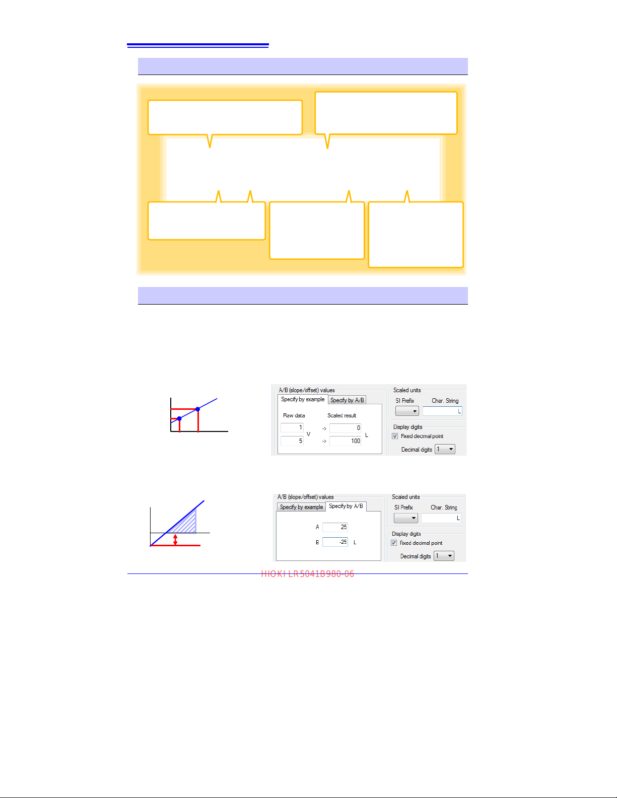
42
Delete Data
Deletes recorded data in the selected logger
(only while connected).
Send PC Clock Time
Set the logger's clock to match the computer's clock (after confirming the computer's
clock is correct).
Copy and Paste Settings
Settings can be copied from another logger. (p.38)
Save Settings *
Saves settings to a computer
file. In the dialog box that appears, specify the location
and name of the destination
file (extension .conf).
Open Settings *
Loads settings from a computer file. In the dialog box
that appears, specify the location and name of the
saved settings file (extension .conf).
* Appears only when [Show the set-
tings of the [Save Settings] and
[Open Settings] buttons.]
is se-
lected on the Options screen.
Actual measured value (raw data)
100
0
5
[V]
(Scaled result)
[L]
1
Offset -25 (coefficient B)
Slope = increase in scaled result / increase in measured value
For the example case, (100 L - 0 L) / (5 V - 1 V) = 25
Slope 25 (coefficient A)
[L]
[V]
100
0
HIOKI LR5041B980-06
3.3 Making Settings from the LR5000 Utility Program
Other Settings on the Logger Settings Screen
What is Scaling?
Scaling converts actual measurement values to their corresponding values in arbitrarily determined units for display. This is convenient for converting the voltage values provided by the logger for display as the corresponding physical values the
sensor is intended to measure.
For example, if a flow sensor provides a 1 to 5 V output signal corresponding to 0 to
100 liters flow measurement, set as follows.
To specify by conversion example
To specify by A/B slope/offset
Find Quality Products Online at: [email protected]
www.GlobalTestSupply.com
Page 47
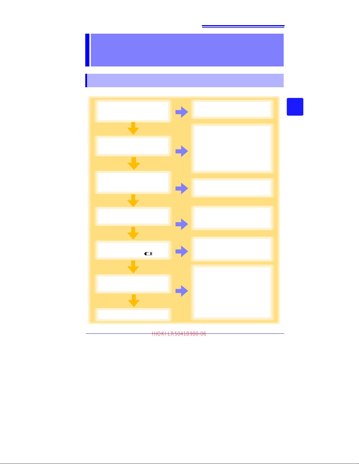
Measurement and
1
2
3
4
5
Is any damage to the logger or connection cable
evident?
No damage
Damaged
Request repair.
See: "Requesting repairs" (p.91)
Is the infrared port damaged or dirty?
No damage
or dirt
Damaged
or dirty
Communication with LR5091 or
LR5092-20 may not be possible.
Clean the infrared port.
See: "9.1 Cleaning" (p.92)
If significant damage is evident,
request repair.
See: "Requesting repairs" (p.91)
Does the display appear
when the battery is
installed?
Display visible
No
display
Request repair.
See: "Requesting repairs" (p.91)
Is the logger clock
correct?
Correct
Incorrect
Set the clock to the current time.
See: "Real-Time Clock Setting"
(p.32)
Does the battery status indicator appear as ( )?
It does
Replace the battery.
See: "2.1 Installing (or Replacing)
the Battery" (p.17)
It does not
Inspection complete!
6
Are voltage values
displayed?
Displayed
Not
displayed
Plug in the connection cable
securely.
See: "2.2 Connecting a Connection
Cable" (p.20)
If not displayed even when the
connection cable is securely
plugged in, request repairs.
See: "Requesting repairs" (p.91)
HIOKI LR5041B980-06
43
4.1 Pre-Measurement Inspection
Analysis
Chapter 4
4.1 Pre-Measurement Inspection
Inspect the following items before starting measurement.
3
4
Chapter 4 Measurement and Analysis
Find Quality Products Online at: [email protected]
www.GlobalTestSupply.com
Page 48
44
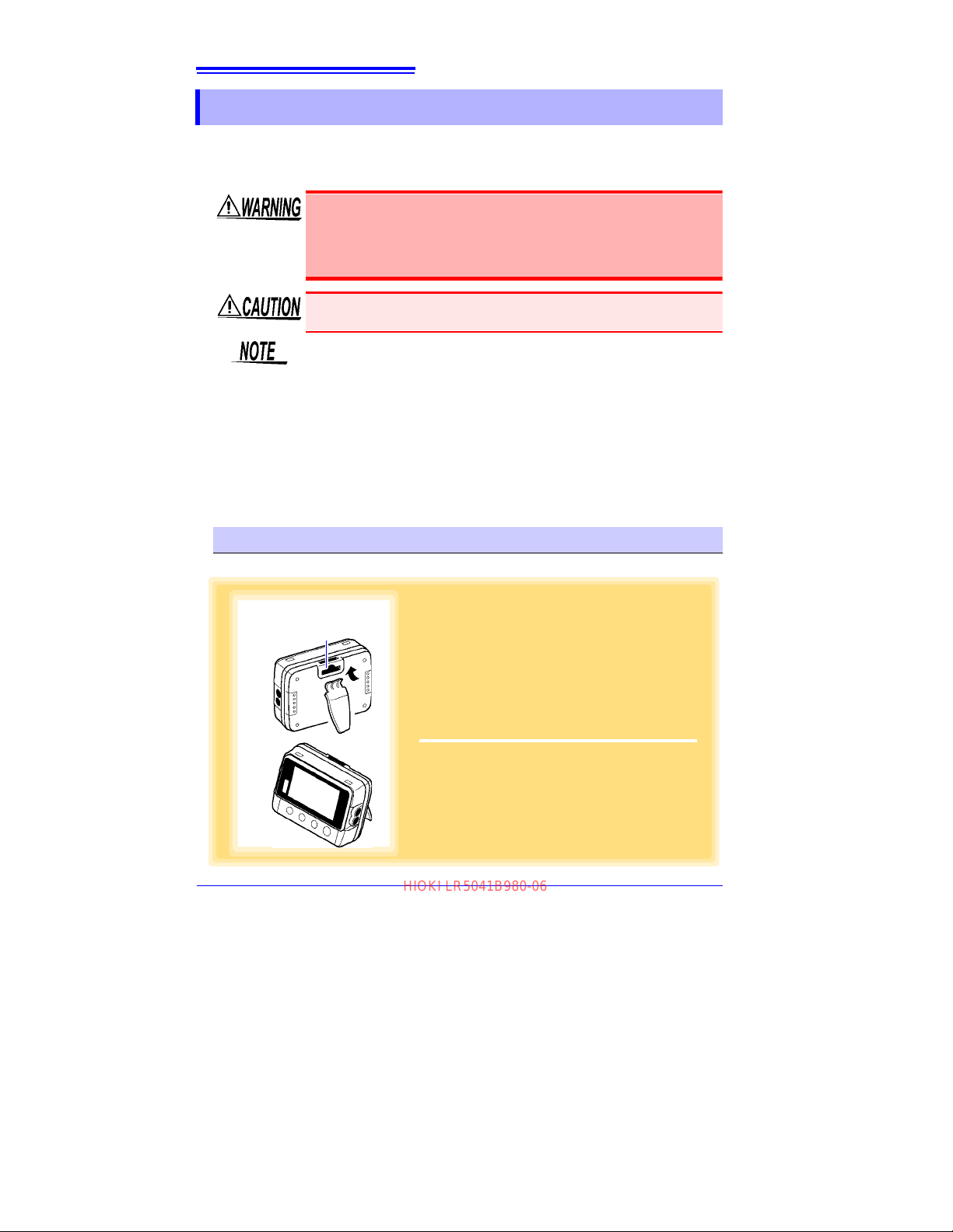
1
Attach the stand to the strap/stand attachment
hole.
2
Stand up the logger.
1
2
Strap/stand attachment hole
HIOKI LR5041B980-06
4.2 Installing the Logger
4.2 Installing the Logger
After inspection, install the logger at the measurement site.
Be sure to read the "Installation Precautions" (p.6) before installing.
Install the logger as necessary according to the following procedure.
Persons wearing electronic medical devices such as a pacemaker
should not use the Z5004 strap with magnet. Such persons should
avoid even proximity to the Z5004, as it may be dangerous. Medical device operation could be compromise
to human life.
Do not apply heavy downward pressure with the stand extended. The
stand could be damaged.
• Avoid shocking the Z5004, such as by dropping. Shock can cause it to
be chipped or cracked.
• Do not use the Z5004 where it may be subject to rain, dust, or condensation. Use in such conditions may cause corrosion or deterioration of
the magnet.
• If t
he Z5004 is brought near a magnetic memory device such as a
floppy disk, credit/debit card, or pre-paid card or ticket, the device may
become unusable due to data corruption. It can also cause damage if
brought near a precision electronic device such as a computer, TV, or
electronic wristwatch.
d, presenting a hazard
Using the Stand
Required Items: Stand (Accessory)
Find Quality Products Online at: [email protected]
www.GlobalTestSupply.com
Page 49
4.2 Installing the Logger
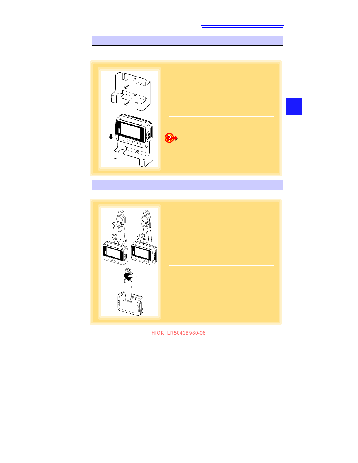
1
Mount the LR9901 to the wall using the two
screws.
2
Insert the logger into the LR9901.
1
2
The logger can also be attached to a wall or
other surface by hanging the strap or attachment hole on a screw. (Supported screw head
dimensions: up to approx. 6.8 mm in diameter
and approx. 2.5 mm in thickness)
1
Attach the Z5004 to the strap/stand attachment hole.
(feed the strap through a, b, and c)
2
Attach the magnet to the wall (ferrous material).
2
1
a
b
c
Magnet
HIOKI LR5041B980-06
Wall Mounting with the LR9901 Wall-Mounted Holder
Required Items: LR9901 (Option), 2 screws (supplied with the LR9901), screwdriver,
etc. (as needed)
45
3
4
Chapter 4 Measurement and Analysis
Wall Mounting with the Z5004 Magnetic Strap
Required Items: Z5004 (Option)
Find Quality Products Online at: [email protected]
www.GlobalTestSupply.com
Page 50
46
HIOKI LR5041B980-06
4.3 Starting and Stopping Recording
4.3 Starting and Stopping Recording
Install the logger, connect the leads to the measurement object, and start recording.
To avoid electrical shock, be careful to avoid shorting live lines
with the connection cable.
• In order to prevent electric shock and short-circuit accidents,
shut off the power to the line to be measured before connecting
the connection cable.
• Ensure that the input does not exceed the maximum rate
age or current to avoid logger damage, short-circuiting and electric s
hock resulting from heat building.
• The maximum rated voltage between input terminals and ground
is 60 VDC. Attempting to measure voltages exceeding 60 V with
respect to ground could damage the logger and result in personal injury.
Recording cannot start when the battery is depleted. When the battery
becomes exhausted during recording, recording stops.
See: "2.1 Installing (or Replacing) the Battery" (p.17)
d volt-
Find Quality Products Online at: [email protected]
www.GlobalTestSupply.com
Page 51
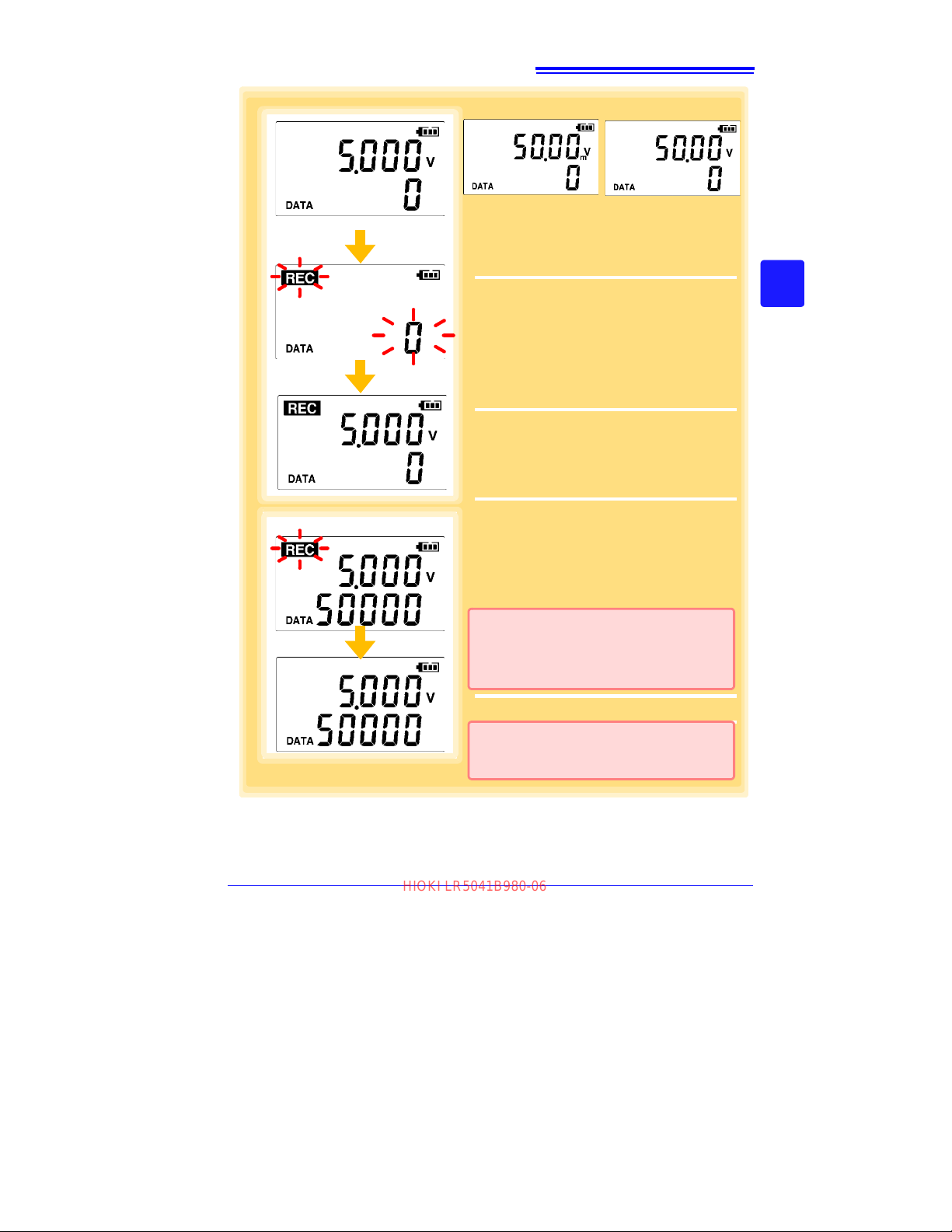
Start
From the Measurement display, hold the
REC/STOP button for two seconds.
The [REC] indicator and the data count blink.
Note: Continue pressing the button until the
[REC] indicator changes from a blink-
ing to on state.
When the blinking stops and the data count is
zeroed, recording starts.
Logger memory contains the data for two
recording sessions. (Be aware that old data is
erased when starting recording after two
recording sessions.)
After one second, the measurement display
reappears.
Stop Hold the REC/STOP button for two sec-
onds while recording (while
[REC] is dis-
played).
[REC] blinks.
Note: Continue pressing the button until the
[REC] indicator changes from a blink-
ing to off state.
[REC] disappears when recording stops.
Start
Stop
If the stop method is set to [OFF] (one-time
recording), recording stops automatically
when memory becomes full.(p.33)
Data can be imported to a computer without
stopping recording.
See: "4.5 Automatically Importing (Saving)
Recorded Data to a Computer, and Graph
Display" (p.49)
(LR5042 Display Example)
(LR5041 Display
Example)
(LR5043 Display
Example)
HIOKI LR5041B980-06
47
4.3 Starting and Stopping Recording
3
4
Chapter 4 Measurement and Analysis
Find Quality Products Online at: [email protected]
www.GlobalTestSupply.com
Page 52
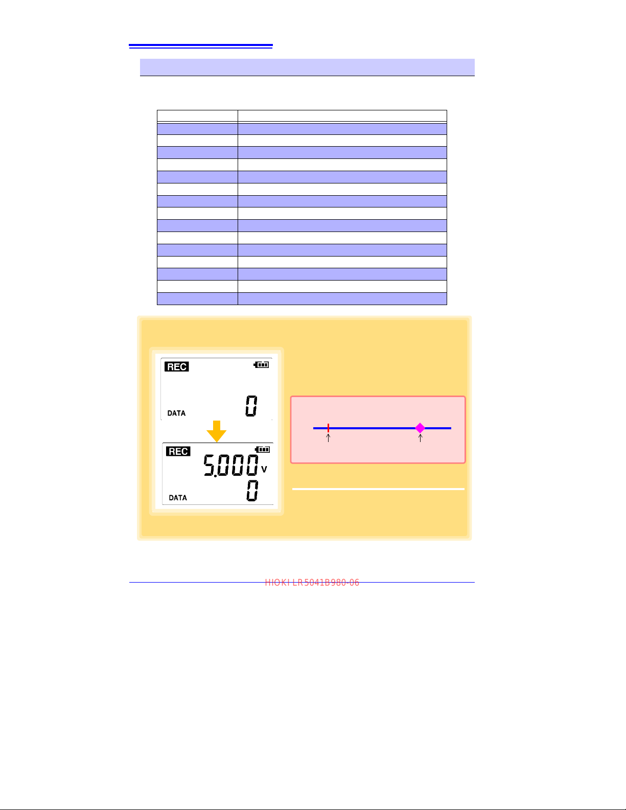
48
At 12:01:00, you press the REC/STOP
button.
The [REC] indicator in the display turns on,
but recording does not start yet.
At 12:10:00
Recording starts.
In the case of instantaneous value recording,
the number of data soon becomes 1.
In the case of statistical value recording, the
number of data becomes 1 at 12:20:00.
Example: When the button is pushed to start recording at 12:01:00,
and the recording interval is 10 minutes
12:01:00
Recording Start Operation
12:10:00
Actual Recording Start
If you try starting at 12:00 but are one minute late
Actual recording starts at 12:10, which is considered
the next convenient time.
HIOKI LR5041B980-06
4.3 Starting and Stopping Recording
Automatic Recording Start at Convenient Times
Depending on the selected recording interval, recording start is automatically delayed
until the next convenient clock time.
Recording Interval Recording Start Time
1 sec. 00 to 59 s (1-second interval)
2 sec.
5 sec. 00 to 55 s (5-seconds interval)
10 sec.
15 sec. 00 to 45 s (15-seconds interval)
20 sec.
30 sec. 00 to 30 s (30-seconds interval)
1 min
2 min 00 min, 00 s to 58 min, 00 s (2-minutes interval)
5 min
10 min 00 min, 00 s to 50 min, 00 s (10-minutes interval)
15 min
20 min 00 min, 00 s to 40 min, 00 s (20-minutes interval)
30 min
60 min 00 h, 00 min, 00 s to 23 h, 00 min, 00 s (1-hour interval)
00 to 58 s (2-seconds interval)
00 to 50 s (10-seconds interval)
00 to 40 s (20-seconds interval)
00 min, 00 s to 59 min, 00 s (1-minute interval)
00 min, 00 s to 55 min, 00 s (5-minutes interval)
00 min, 00 s to 45 min, 00 s (15-minutes interval)
00 min, 00 s to 30 min, 00 s (30-minutes interval)
Find Quality Products Online at: [email protected]
www.GlobalTestSupply.com
Page 53
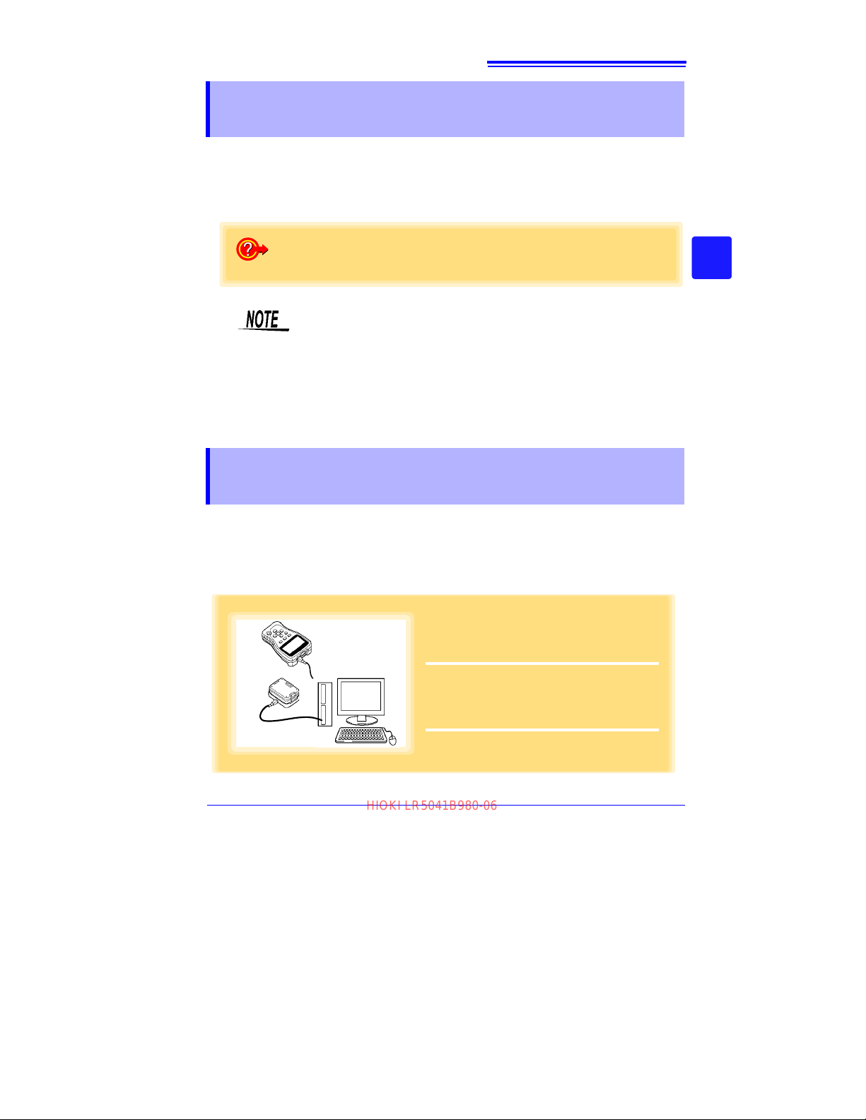
49
How to switch from a Setting display to Measurement display?
To switch to the Measurement display from any other display, press REC/STOP.
1
Plug the USB cable into the USB port on
the LR5091 (or LR5092-20), and into a
USB port on the computer.
2
Dock the logger in the LR5091 (or LR5092-
20).
(When docking, be sure that the infrared ports
are aligned.)
or
HIOKI LR5041B980-06
4.4 Confirming Currently Measured Values and Data Recording
4.4 Confirming Currently Measured Values and
Data Recording
Confirm data recording on the Measurement display (p.14).
You can browse current measurement values (instantaneous), the count of
recorded data items, and maximum and minimum values.
The (+) and (-) buttons select the type of value displayed.
• When power saving (p.34) is enabled, the display blanks after no
operation occurs for 30 seconds. To browse measurement values
(instantaneous)
to turn on the Measurement display.
• The currently displayed instantaneous measurement value is
refreshed
setting.
and verify each recorded data value, press any button
about once per second, regardless of the recording interval
3
4
Chapter 4 Measurement and Analysis
4.5 Automatically Importing (Saving) Recorded Data to a Computer, and Graph Display
Data recorded in the logger can be imported to th
Utility Program on the computer beforehand. (p.23)
Required Items: Logger, LR5091 Communication Adapter (or LR5092-20 Data Collector), USB cable, and Computer
e computer. Install the LR5000
Find Quality Products Online at: [email protected]
www.GlobalTestSupply.com
Page 54
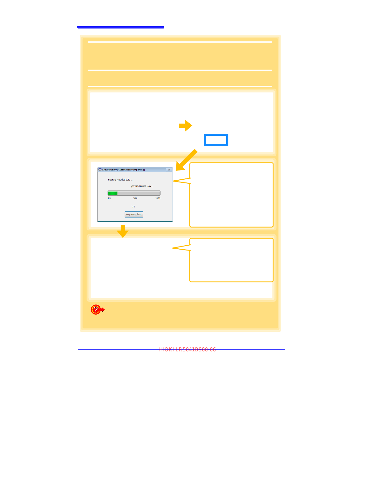
50
The main screen appears automatically.
If newly recorded data exists, the import confirmation dialog appears.
If the data import screen is displayed before connecting the logger, the import confirma-
tion dialog does not appear. Import manually. (p.59)
3
Click [Yes].
The viewer opens to display the
graph (Auto Graph Display).
Note: By default, [Automatically dis-
play graph when data is
imported] (on the Options
screen) is enabled. (p.82)
The data recorded in the logger is
imported to the computer automatically.
Imported data is saved to a file
(Auto Import).
Note: By default, [Automatically
import and store data when
the logger is connected to a
computer] (on the Options
screen) is enabled. (p.82)
How is recorded data saved?
Recorded data is automatically saved when imported to a computer.
The save destination and file name are specified as a basic setting on the
Options screen.
3
HIOKI LR5041B980-06
4.5 Automatically Importing (Saving) Recorded Data to a Computer, and Graph Display
Find Quality Products Online at: [email protected]
www.GlobalTestSupply.com
Page 55
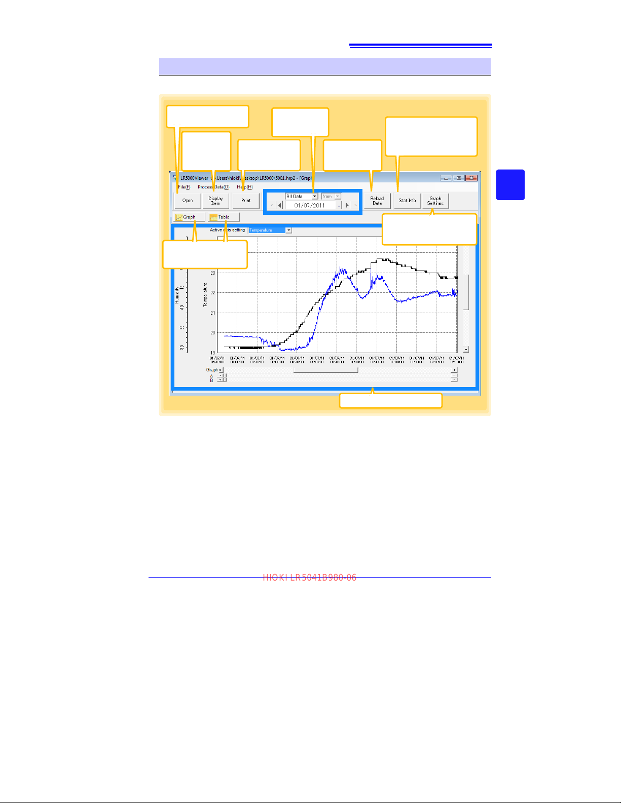
51
Items to be
displayed are
selectable.
(p.58)
Opens a file containing
recorded data.
Displayed graphs
and tables can be
printed. (p.64)
The displayed
time span can
be specified.
Reloads and refreshes recorded
data from a file.
Displays the [Statistical
In-formation and Item
Settings] dialog box when
a graph is displayed. (p.56)
Click the buttons to
switch between graph
and table displays.
Displays the [Graph Set-
tings] dialog box when a
graph is displayed. (p.54)
The graph or table is displayed.
See: "Menu Bar Items" (p.52)
HIOKI LR5041B980-06
4.5 Automatically Importing (Saving) Recorded Data to a Computer, and Graph Display
Viewer Screen
The viewer screen appears as follows.
3
4
Chapter 4 Measurement and Analysis
Find Quality Products Online at: [email protected]
www.GlobalTestSupply.com
Page 56
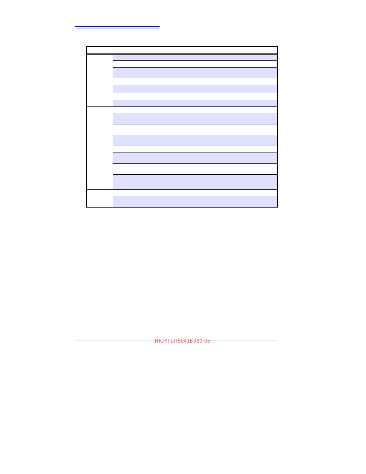
52
HIOKI LR5041B980-06
4.5 Automatically Importing (Saving) Recorded Data to a Computer, and Graph Display
Menu Bar Items
Menu Item Contents
Open Opens a file containing recorded data.
File
Data
Processing
Help
Recently opened recording files
Save recording file as
Print graph Prints data in graphic format. (p.64)
Paste to Microsoft Excel
Export CSV file
Exit Closes the program.
Scaling Applies scaling to data on one channel. (p.67)
Power Calculation
Energy Cost
Operating Rate
Integration Performs data integration. (p.71)
Dew Point
Two-Data-Item Arithmetic
OVER Data Revision
Help
Version
®
Opens recently used files.
Currently displayed recording data is saved as a
new file.
Pastes displayed data into Microsoft Excel®.
Exports displayed data as a CSV file.
Performs approximate electric power calculation.
(p.68)
Performs approximate energy cost calculation.
(p.69)
Performs approximate operating rate calculation.
(p.70)
Performs dew-point temperature calculation.
(p.72)
Performs approximate two-data-item arithmetic calculation. (p.73)
Converts data outside of the upper and lower threshold settings to specified values, and saves as ne
data. (p.74)
Displays the help file.
Displays LR5000 Utility Program version informa-
tion.
w
Find Quality Products Online at: [email protected]
www.GlobalTestSupply.com
Page 57
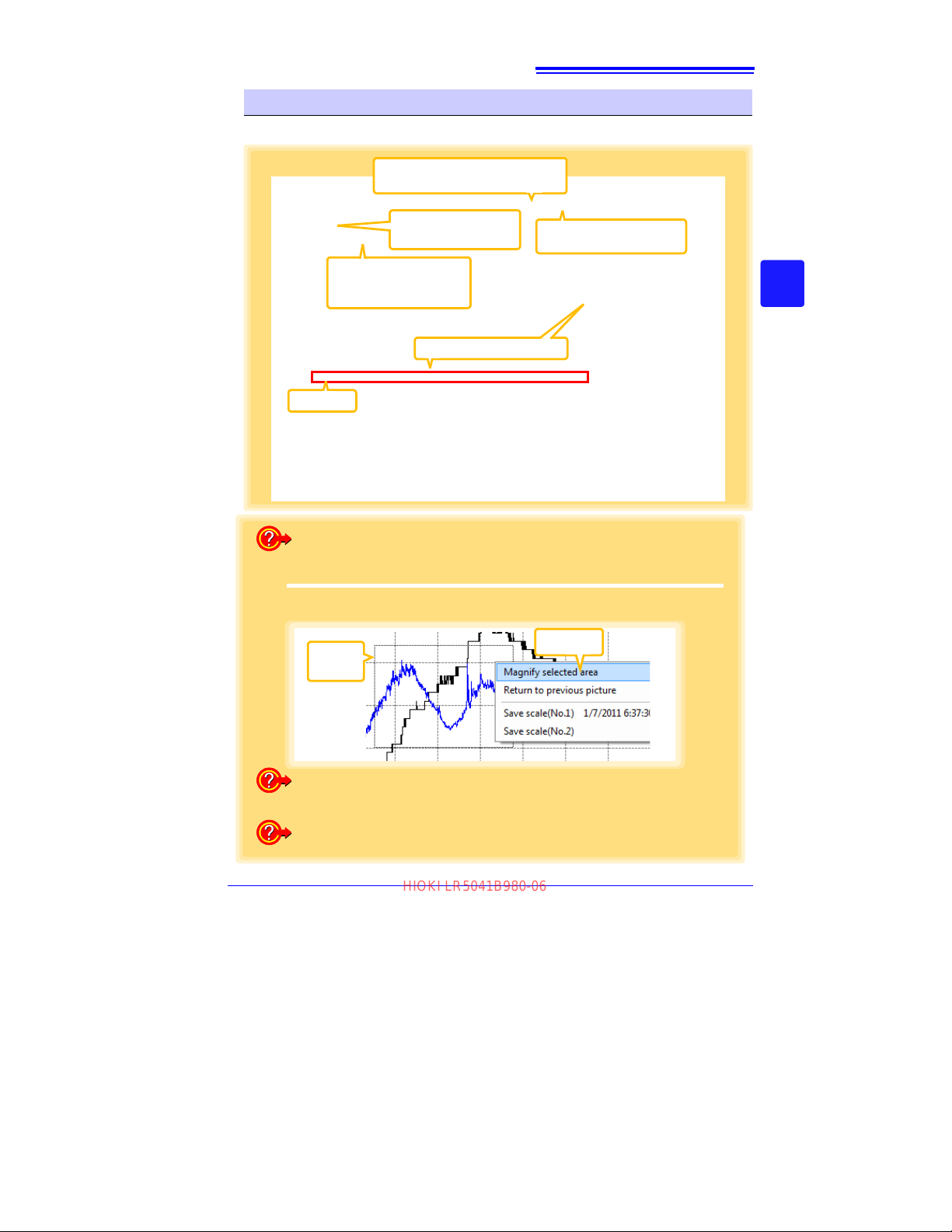
53
Click the buttons to
switch between graph
and table displays.
Displays the [Statistical Information
and Item Settings] dialog box. (p.56)
Displays the [Graph Settings]
dialog box. (p.54)
A/B cursors
Scroll Bar (scrolls the graph)
When there are two or
more axes, select the one
displayed closest to the
graph.
How can the displayed area be magnified?
Dotted
Box
Click
2
1
Drag over the area to be enlarged to enclose it in a dotted box.
2
Right click to open the pop-up menu, and click [Magnify selected area].
How can graph details be set?
Detailed settings are available in the [Graph Settings] dialog box. (p.54)
How can graph line color and display be switched?
Change settings on the [Item Settings] tab in the [Statistical Information and Item
Settings]
dialog box (p.56)
HIOKI LR5041B980-06
4.5 Automatically Importing (Saving) Recorded Data to a Computer, and Graph Display
Main Graph Features
The main graph features are shown below.
3
4
Chapter 4 Measurement and Analysis
Find Quality Products Online at: [email protected]
www.GlobalTestSupply.com
Page 58
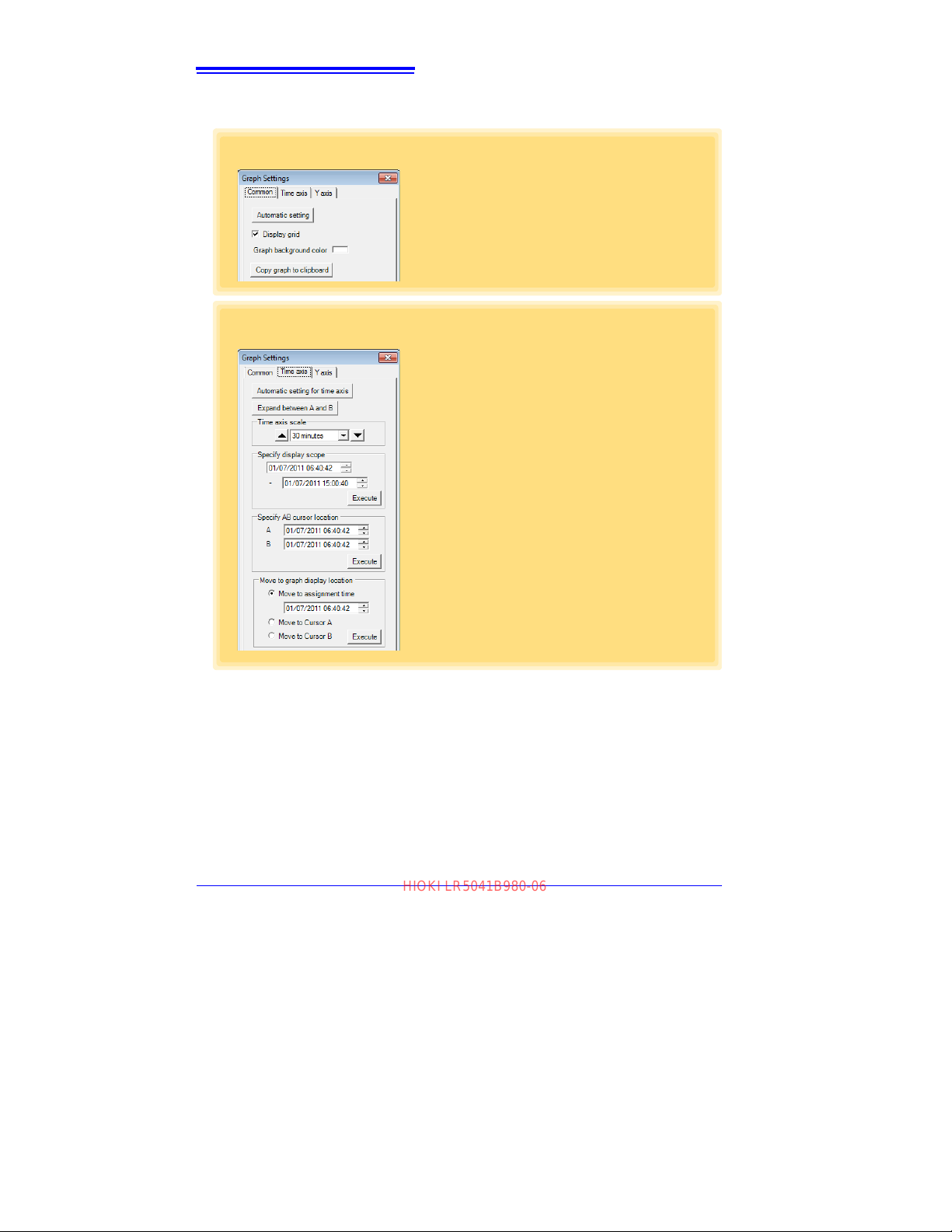
54
[Common] tab
1
Automatically sets the time axis and Yaxis to the optimum scale.
2
Select to display the grid.
3
Changes the graph background color.
4
Copies the graph to the clipboard. The
graph can then be pasted into Microsoft
Word etc .
1
2
3
4
[Time axis] tab
1
Automatically sets the time axis to the
optimum scale.
2
Zooms the display to show only the time
span between A/B cursors.
3
Changes the time base scale.
4
Specifies the displayed time span on the
time axis. Click
[Execute] to apply the set-
tings.
5
Specifies cursor positions. Click [Exe-
cute]
to apply the settings.
6
Specifies the graph start position (time).
Click
[Execute] to apply the settings.
1
2
3
4
5
6
HIOKI LR5041B980-06
4.5 Automatically Importing (Saving) Recorded Data to a Computer, and Graph Display
[Graph Settings] dialog box
Graph details can be set as follows. Click each tab to access various settings.
Find Quality Products Online at: [email protected]
www.GlobalTestSupply.com
Page 59
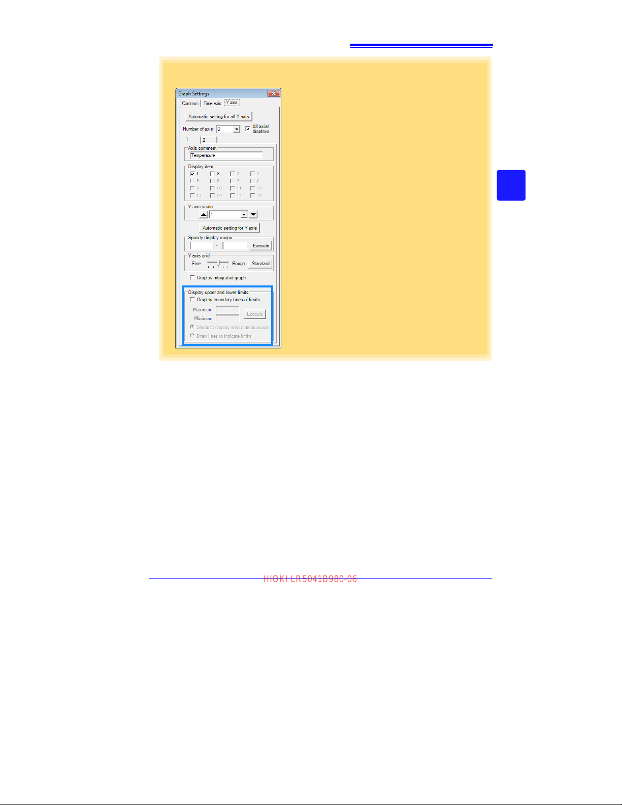
55
[Y axis] tab
1
Automatically sets all Y-axes to the optimum scale.
2
When the Y-axis is different for each item,
set the number of axes to a value other
than one. The axes can be set to the
number of displayed items (up to 16).
3
Displays all axes.
4
A comment can be entered for each axis.
5
Select the item assigned to each axis.
6
Sets the Y -axis scale for each axis.
7
Automatically sets the currently selected
Y-axis to the optimum scale.
8
Specifies the display span on the Y-axis.
Click
[Execute] to apply the settings.
9
Sets the Y-axis grid spacing.
10
Display the items selected in [Display
item] on an integrated graph.
11
Upper and lower thresholds can be displayed as solid lines on the graph, or outof-range areas can be filled with a solid
color.
1
2
4
5
6
7
3
8
9
11
10
HIOKI LR5041B980-06
4.5 Automatically Importing (Saving) Recorded Data to a Computer, and Graph Display
3
4
Chapter 4 Measurement and Analysis
Find Quality Products Online at: [email protected]
www.GlobalTestSupply.com
Page 60
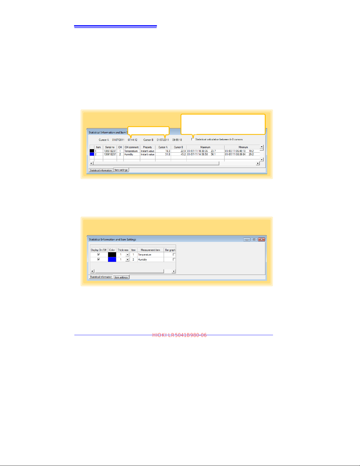
56
[Statistics] tab
Times at A/B cursors
Select to calculate and display maximum,
minimum, average, and integration values
between A/B cursors. Integration values are
displayed only for integrable items.
[Item settings] tab
HIOKI LR5041B980-06
4.5 Automatically Importing (Saving) Recorded Data to a Computer, and Graph Display
[Statistical Information and Item Settings] dialog box
The following items appear on the [Statistical information] tab.
• Item no.
• Serial no.
• Channel no.
• Channel comments
• Property (Type of measurement value)
• Measured values at A/B cursors
• Statistical data
•Units
The following items appear on the [Item sett
• Display on/off
• Graph line colors and thickness
• Bar graph display on/off
ings] tab.
Find Quality Products Online at: [email protected]
www.GlobalTestSupply.com
Page 61
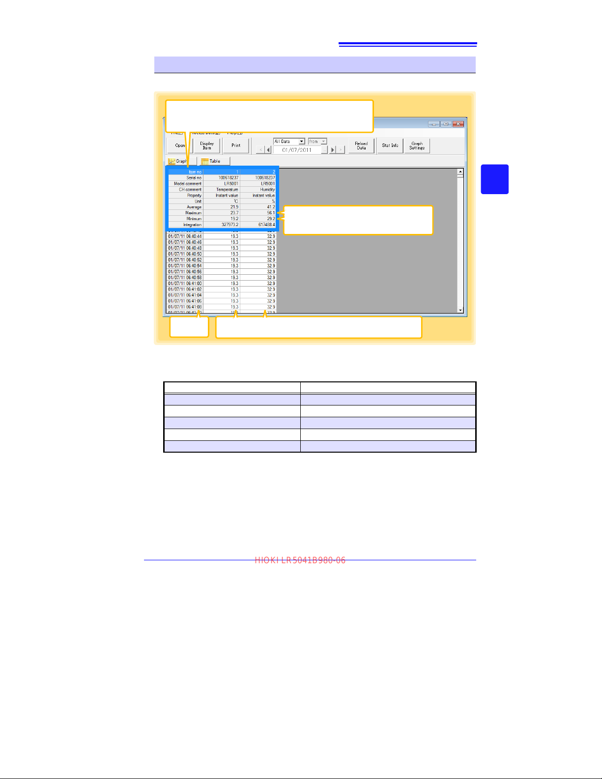
57
Shows the item no., serial no., model comment, channel comment, property, measurement units, and average, maximum, minimum, and integration values of all data.
Double click a maximum or minimum numerical value to jump to the relevant cell (or to the
first if there are multiple relevant cells).
Time of
Recording
Recorded Values
Blue indicates minimum values, and red indicates maximum values.
HIOKI LR5041B980-06
4.5 Automatically Importing (Saving) Recorded Data to a Computer, and Graph Display
Main Table Features
The main table features are shown below.
3
4
Chapter 4 Measurement and Analysis
Convenient Table Functions
Use the following operations to scroll the table and copy data to the clipboard.
Press Ctrl and Home keys simultaneously
Press Ctrl and End keys simultaneously
Home key
End key
Press Ctrl and C keys simultaneously
Item Contents
Moves to the upper left corner of the table.
Moves to the lower right corner of the table.
Scrolls to display the left edge of the table.
Scrolls to the right edge of the table.
Copies the value of the currently selected cell to the clipboard.
Find Quality Products Online at: [email protected]
www.GlobalTestSupply.com
Page 62
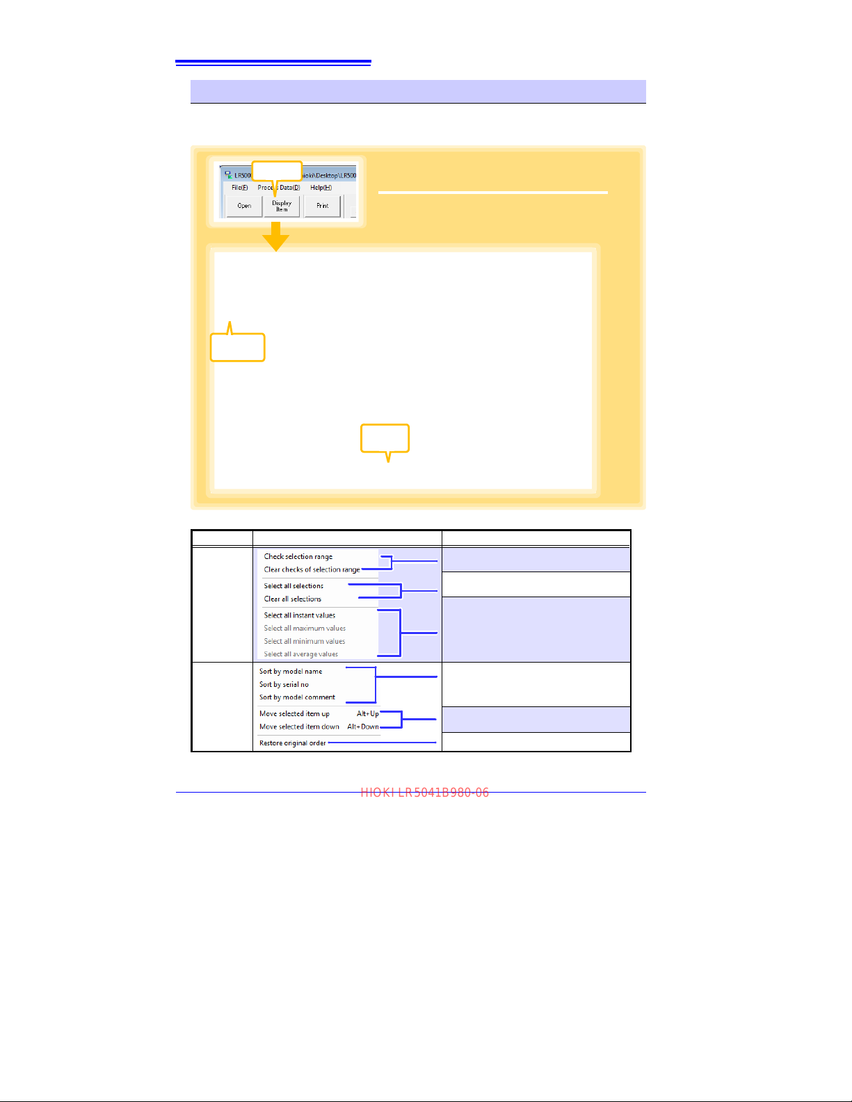
58
Click
1
Select up to 600 items for display.
2
Click the [OK] button.
Check
1
Click
2
HIOKI LR5041B980-06
4.5 Automatically Importing (Saving) Recorded Data to a Computer, and Graph Display
Selecting Items for Display
Click the [Display Item] button in the viewer to display the [Select Items for Display]
screen.
Menu Bar Items
Menu Items Contents
Add and clear selection of multiple items
(display in blue) selected with the mouse.
When there are 600 item in the above list,
click to select or clear all items.
Select Items
Select all items (up to 600) of the same
property.
Sort by model name, serial no., or model
.
comment
Sort Items
Move blue mouse-selected items up or
down.
Restore original order.
Find Quality Products Online at: [email protected]
www.GlobalTestSupply.com
Page 63
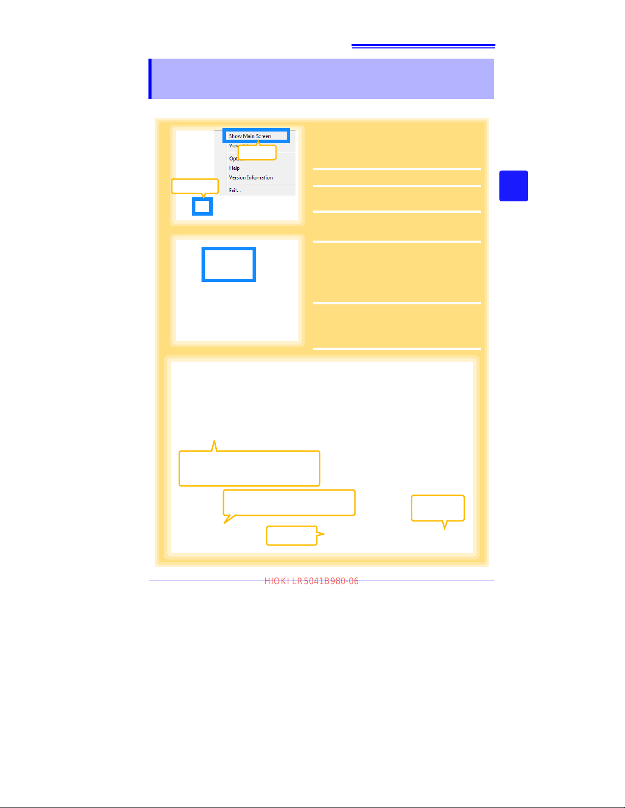
59
2
Click to select.
The currently selected logger’s background is a different color.
3
3
Returns to the
main screen.
Click
Click
1
1
If the LR5000 Utility Program is not running on the computer, click the icon in the
task tray (notification area), and click
[Show Main Screen].
The main screen appears.
2
For the [Data Import] device, click the
[Logger] button.
The Data Import screen appears. If the logger
is not connected, you are prompted to connect it. Connect the logger.
3
Select the logger in the list of devices, and
click the [Start Importing] or [Next]* button.
* If [Always specify folder and file
before importing]
on the Options screen
is enabled (p.82).
If you click the [Start Importing] button,
data importing starts ("Screen after importing
data" (p.61)).
If you click
[Next], the Save Method screen
appears (p.60).
If multiple devices are listed, they can
be sorted in ascending order.
See: p.61
HIOKI LR5041B980-06
4.6 Manually Importing (Saving) Recorded Data to a Computer, and Graph Display
4.6 Manually Importing (Saving) Recorded Data
to a Computer, and Graph Display
You can manually import (save) recorded data to a computer, and display it in a graph.
3
4
Chapter 4 Measurement and Analysis
Find Quality Products Online at: [email protected]
www.GlobalTestSupply.com
Page 64
60
If the previous data has not been imported, information is displayed along with the latest data.
After making the [Import Data Selection], click the
[Start Importing] or [Next] button.
Method 1
Edit the save destination (basic setting).
Note: The Options screen settings (p.82) are re-
freshed.
Select the save method.
Three methods are available.
4
Click
5
Method 2
Specify an existing file.*
Method 3
Specify the file naming
method and save destination folder.*
Save Method Screen
See: p.61
* When data from the same logger already exists, newly recorded data is ap-
pended to it if recording has not been stopped, or saved as a new item if recording has since been stopped.
The Save Method screen will appear when the [Always specify folder and file before importing]
checkbox on the optional screen is selected.
See:
"7.1 Changing the Saving Method for Imported Data" (p.82)
HIOKI LR5041B980-06
4.6 Manually Importing (Saving) Recorded Data to a Computer, and Graph Display
Find Quality Products Online at: [email protected]
www.GlobalTestSupply.com
Page 65
61
How can all data be imported from the logger?
Select [Re-import all data from the logger].
(All data in the logger (including any previously imported) is imported to the co mputer, and duplicated data is overwritten.)
How is the graph automatically displayed after importing data?
Select [Display gra ph automatically after importing data].(When not selected,
the file list is saved and displayed when importing is finished.)
Save Method Screen(p.60)
Data Import screen(p.59)
How is automatic importing performed?
On the Options screen, enable [Automatically import and store data when the
logger is connected to a computer]. (p.82)
Screen after importing data
Click the button to display the graph.
If there are more than 16 items to display, the
display item selection screen appears. Select
the items to be displayed in the graph. (p.58)
Click the button to display
the table.
The Logger Settings screen
appears.
Displays the Data Import screen (p.59).
Returns to the
main screen.
HIOKI LR5041B980-06
4.6 Manually Importing (Saving) Recorded Data to a Computer, and Graph Display
3
4
Chapter 4 Measurement and Analysis
Find Quality Products Online at: [email protected]
www.GlobalTestSupply.com
Page 66
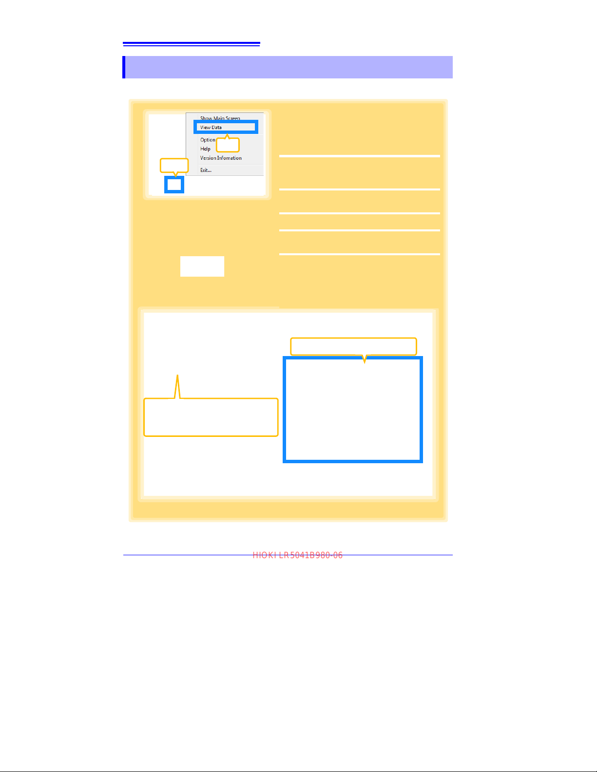
62
Click to select.
The currently selected logger’s
background is a different color.
2
3
Information about the latest data
1
1
If the LR5000 Utility Program is not running on the computer, click the icon in the
task tray (notification area), and click
[View Data].
The Data View screen appears.
The
[View latest data] tab shows a list of the
loggers with data saved on the comput er.
2
Select the logger from the list.
Information about the latest data appears.
3
Click the [Display Graph] button.
The viewer opens to display the graph
(p.51).
If there are more than 16 items to display, the
display item selection screen appears. Select
the items to be displayed in the graph
(p.58).
Note: If the LR5000 Utility Program is
running, click [View Data] on the main
screen.
Click
Click
HIOKI LR5041B980-06
4.7 Displaying a Graph of Saved Recording Data
4.7 Displaying a Graph of Saved Recording Data
Use the LR5000 Utility Program to display saved recording data as a graph.
Find Quality Products Online at: [email protected]
www.GlobalTestSupply.com
Page 67
4.7 Displaying a Graph of Saved Recording Data
Filter displayed data
You can filter which loggers appear in the list. Specify the
desired filtering criteria, and click the [Refresh List] button.
Note: You can enter up to 20 characters for [Filter by Mod-
el Comment].
Display Table
Opens the viewer to display the
table of imported (or selected)
data.
How can past data be viewed?
On the [Search Folders] tab, select the folder and file name to display.
Recently folders
The last ten folders containing data
that was displayed as a graph or table are listed.
Select the drive
2
Select the folder
3
Select the file
4
Click
1
HIOKI LR5041B980-06
Other Data Viewing Screen Functions
63
3
4
Chapter 4 Measurement and Analysis
Find Quality Products Online at: [email protected]
www.GlobalTestSupply.com
Page 68
64
Click
Example Graph Printout
How can I print only part of a graph?
Specify the time span to print, and click
[Print] button. Times that are not displayed
are not printed.
See: "Viewer Screen" (p.51)
HIOKI LR5041B980-06
4.8 Printing Recorded Data
4.8 Printing Recorded Data
Saved recording data can be printed as a graph. Graphs displayed in the LR5000
Utility Program can be printed on A3, A4, or B4-size paper.
With the desired graph displayed, click the [Print] button.
See:Graph Display Methods:"4.5" (p.49),"4.6" (p.59), and"4.7" (p.62)
Find Quality Products Online at: [email protected]
www.GlobalTestSupply.com
Page 69
Processing
Click to select.
The currently selected logger's
background is a different color.
2
3
Information about the latest data
1
Continued →
Note: If the LR5000 Utility Program is
running, click [View Data] on the
main screen.
Click
Click
1
If the LR5000 Utility Program is not runni ng
on the computer, click the icon in the task
tray (notification area), and click [View
Data].
The Data View screen appears.
The
[View latest data] tab shows a list of the
loggers with data saved on the comput er.
2
Select the logger from the list.
Information about the latest data appears.
3
Click the [Display Graph] button.
The viewer opens to display the graph
(If there are 16 or more items to display, the dis-
play item selection screen appears. Select the
data items for processing.) (p.58).
HIOKI LR5041B980-06
65
Recorded Data
Recorded data saved on the computer can be processed by scaling, electric power
calculation, energy cost calculation, operating rate calculation, integration, dewpoint temperature calculation, two-item arithmetic calculation, and out-of-range
data revision. The LR5000 Utility Program performs the calculations.
Chapter 5
3
5
Chapter 5 Processing Recorded Data
Find Quality Products Online at: [email protected]
www.GlobalTestSupply.com
Page 70
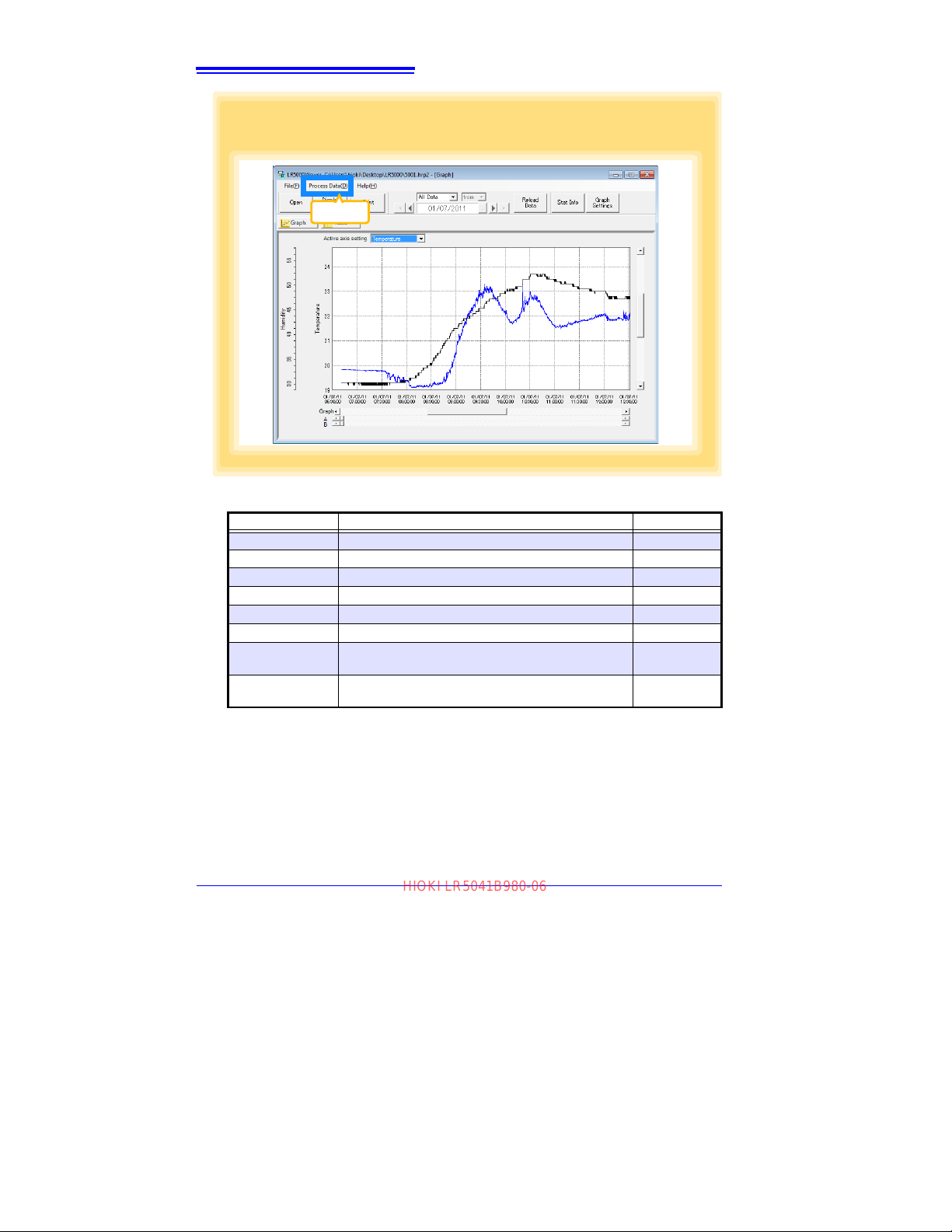
66
4
Click [Process Data] in the menu bar, and select the desired items.
Click
HIOKI LR5041B980-06
[Process Data] Items
Items Contents See
Scaling
Power Calculation
Energy Cost
Operating Rate
Integration
Dew Point
Two-Data-Item
Arithmetic
OVER Data
Revision
Performs scaling on the data of one channel. (p.67)
Performs approximate electric power calculation. (p.68)
Performs approximate energy cost calculation. (p.69)
Performs approximate operating rate calculation. (p.70)
Integrates displayed data. (p.71)
Performs dew-point temperature calculation. (p.72)
Performs approximate two-data-item arithmetic calculation. (p.73)
Converts data outside of the upper and lower threshold settings to specified values, and saves as new data items.
(p.74)
Find Quality Products Online at: [email protected]
www.GlobalTestSupply.com
Page 71
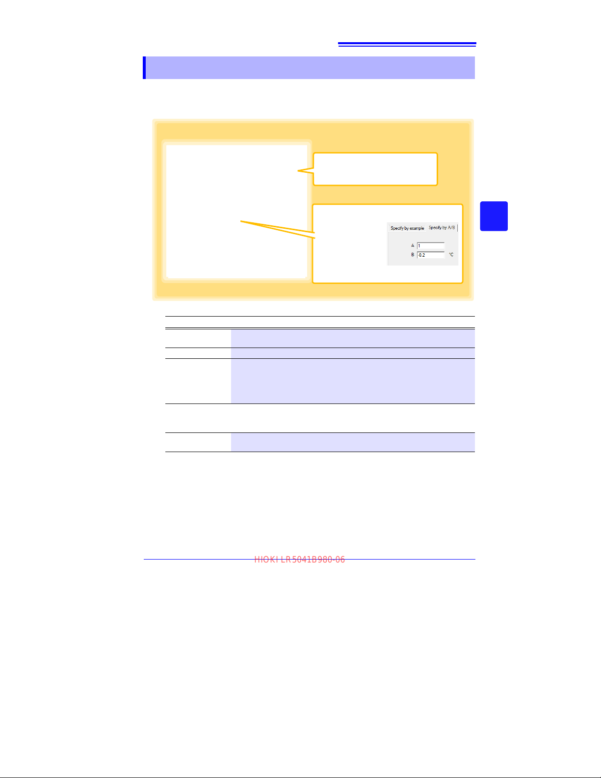
5.1 Scaling
Item and range settings
Select the item to be scaled, and the
time span.
Clicking this tab
changes the setting
options. Make settings on either tab.
(The settings are applied to the other
tab.)
A/B (slope/offset) values
1
2
3
1
1
HIOKI LR5041B980-06
The following scaling calculation is applied to measured values.
Scaled Result = Raw data (measured value) × A + B × SI prefix (multiplier)
Scaled results are saved as a new item in the recording file.
67
5.1 Scaling
3
5
Chapter 5 Processing Recorded Data
1. Select the items, time span, and the following options.
Setting Options
Specify by
example *
Specify by A/B * Enter the scaling coefficients (A and B, up to ten digits each).
Scaled units
* Set either one.
Description
Enter two known conversion points (up to ten digits each).
• Select the [SI Prefix].
([p]=1E-12, [n]=1
[G]=1E9, [T]=1E12)
• Enter a character string to identify the scaled units.
• (Up to five characters, except \, /, :, *, ?, ", <, >, and |.)
E-9, [μ]=1E-6, [m]=1E-3, blank =1E0, [k]=1E3, [M]=1E6,
2. Confirm settings.
Setting
confirmation
Confirm that scaling is performed properly.Enter any numerical value as raw
data, and click the [Calculate] button to display the scaled result.
3. Click the [Execute] button.
(The
scaled results are saved.)
Note: Click the [Finish] button to close the [Scaling] dialog box.
Find Quality Products Online at: [email protected]
www.GlobalTestSupply.com
Page 72
68
Item and range settings
Specify two measured current values
and the time span for calculation.
[Electric Power Type]
Choose [1P2W], [1P3W] or [3P3W] to select the appropriate calculation formula.
Calculation formula
1
1
2
3
HIOKI LR5041B980-06
5.2 Calculating Electric Power
5.2 Calculating Electric Power
Approximate electric power is calculated using current measurement data from a
clamp logger.
Calculation results are saved as a new item in the recording file.
• Electric power calculations are only approximate, so results do not
always equal the true electric power value. Use a wattmeter if accu
rate power measurements are required.
• There is no way to confirm that a specified data item is really a current
value. Calculation occurs regardless of data type.
-
1. Select the items, time span, and calculation formula to be used.
2. Specify the voltage, power factor, and units.
•To save the settings, click the [Register] button.
•To apply a registered setting, double click it ("S
•To delete a setting, click it then click the [Delete] butto
3. Click the [Execute] button.
(Calculation results are saved.)
Note: Click the [Finish] button to close the [Power Calculation] dialog box.
etting1” in the above screenshot).
n.
Find Quality Products Online at: [email protected]
www.GlobalTestSupply.com
Page 73
5.3 Calculating Energy Cost
Item and range settings
Specify the measured current value and the time
span for calculation.The time span can also be
specified by setting the A/B cursors (p.53) on a
graph and selecting [Calculate between A/B
cursors].
1
2
3
HIOKI LR5041B980-06
5.3 Calculating Energy Cost
Approximate energy cost is calculated using current measurement data from a clamp
logger.
• Energy cost calculations are only approximate, so results do not
always equal the true energy cost.
• There is no way to confirm that a specified data item is really an electric power value. Calculation occurs regardless of data type.
69
3
5
Chapter 5 Processing Recorded Data
1. Select the item and time span.
2. Specify the cost per kWh, voltage, and power factor.
3. Click the [Calculate] button.
(Electric power consumption and energy cost values are calculated and displayed.)
Note: Click the [Finish] button to close the [Energy Cost] dialog box.
Find Quality Products Online at: [email protected]
www.GlobalTestSupply.com
Page 74
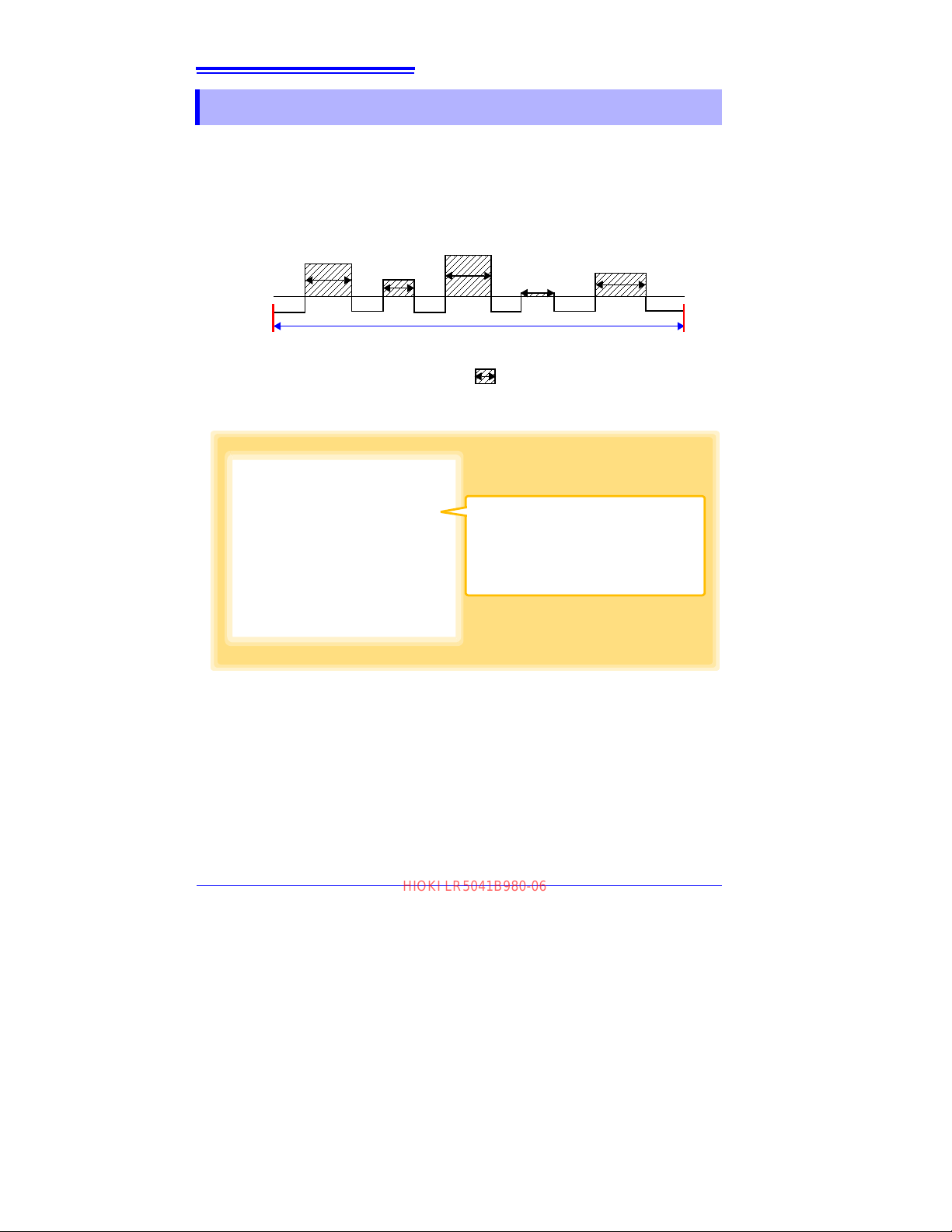
70
Item and range settings
Select the item for operating rate calculation,
and the time span.
The time span can also be specified by setting
the A/B cursors (p.53) on a graph and selecting
[Calculate between A/B cursors].
1
2
3
Upper
Threshold
20
Example: The time during which a device consumes 20 A or more is
considered the operating time.
The sum of the times depicted by ( ) is the operating time. (In the
above diagram, operating time is 1.5 hours.)
20 min
10 min
20 min
15 min
25 min
Operating time (1.5 h) ÷ calculation time span (2.5 h) × 100 = 60 % operating rate
Calculation time span (2010/1/1 10:00 to 2010/1/1 12:30)
HIOKI LR5041B980-06
5.4 Calculating Operating Rate
5.4 Calculating Operating Rate
The approximate operating rate of the measured value is calculated.
The total amount of time during which data exceeds the [Upper threshold] is considered operating time, and the operating rate is calculated as the ratio of the operating
time to the total calculation time span.
1. Select the item and time span.
2. Set the upper threshold.
3. Click the [Calculate] b
(Operating hours and operating rate values are calculated and displayed.)
Note: Click the [Finish] button to close the [Operating Rate] dialog box.
utton.
Find Quality Products Online at: [email protected]
www.GlobalTestSupply.com
Page 75
5.5 Integration
Item and range settings
Select the item to be integrated, and the
time span.
1
2
HIOKI LR5041B980-06
Measurement data can be integrated over a specified time span.
Integration results are saved as a new item in the recording file.
1. Select the item and time span.
2. Click the [Execute] button.
(Integration results are saved.)
Note: Click the [Finish] button to close the [Integration] dialog box.
71
5.5 Integration
3
5
Chapter 5 Processing Recorded Data
Find Quality Products Online at: [email protected]
www.GlobalTestSupply.com
Page 76
72
Item and range settings
Specify the temperature and humidity values,
and the time span for calculation.
1
2
HIOKI LR5041B980-06
5.6 Calculating Dew-Point Temperature
5.6 Calculating Dew-Point Temperature
Dew-point temperature is calculated from the temperature and humidity measurement
data from the logger.
Calculation results are saved as a new item in the recording file.
• There is no way to confirm that a specified data item is really a temperature or humidity value. Dew-point calculation occurs regardless of
data type.
• Only the specified temperature and humidity data measured during
the specified recording time span is applied to calculations and sa ved.
• The valid range for calculation input measurement data is -100 to 100
degrees, and 0 to 100% humidity. Values outside of these ranges are
replaced with the maximum or minimum value within the valid range.
1. Select the items and time span.
2. Click the [Execute] butt
culation results are saved.)
(Cal
Note: Click the [Finish] button to close the [Dew Point] dialog box.
on.
Find Quality Products Online at: [email protected]
www.GlobalTestSupply.com
Page 77
5.7 Two-Data-Item Arithmetic Calculations
Item and range settings
Select the items for calculation, and the time
span.
1
2
3
HIOKI LR5041B980-06
5.7 T wo-Data-Item Arithmetic Calculations
Simple arithmetic operations (+, -, *, and /) can be applied to two data items.
Calculation results are saved as a new item in the recording file.
Only the values of data items measured during the specified recording
time span are applied to calculations and saved.
73
3
5
Chapter 5 Processing Recorded Data
1. Select the items and time span.
2. Select the calculation operator.
3. Click the [Exec
(Calculation
Note: Click the [Finish] button to close the [Two-Data-Item Arithmetic] dialog box.
ute] button.
results are saved.)
Find Quality Products Online at: [email protected]
www.GlobalTestSupply.com
Page 78
74
Item and range settings
Select the items for conversion, and the time
span.
1
2
3
HIOKI LR5041B980-06
5.8 Converting Over-Threshold Data Values
5.8 Converting Over-Threshold Data Values
Data values larger than the upper threshold and smaller than the lower threshold can
be converted to specified values.
Converted results are saved as new data items in the recording file.
1. Select the items and time span.
2. Set the upper and lower threshold values, and their corresponding conversion values.
3. Click the [Execute] button.
(Conversio
Note: Click the
n results are saved.)
[Finish] button to close the [OVER Data Revision] dialog box.
Find Quality Products Online at: [email protected]
www.GlobalTestSupply.com
Page 79
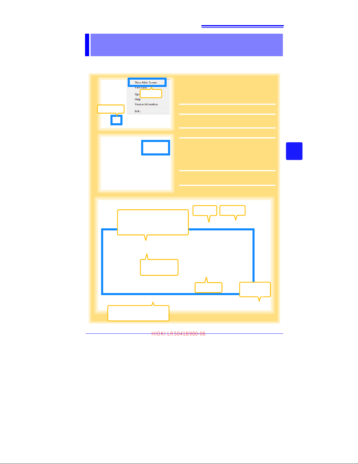
75
2
Returns to the
main screen.
Select
3
4
Click
Select
4
Recently opened folder
The last ten folders containing data
that was displayed as a graph or table are listed.
Select the
desired file.
Clears all selections
(removes check marks).
Click
Click
1
If the LR5000 Utility Program is not running on the computer, click the icon in the
task tray (notification area), and click
[Show Main Screen].
The main screen appears.
2
Click the [Organize Data] button.
The data reorganization screen appears.
3
Select the [Operation Type].
See: "6.1 Copying and Moving Data" (p.76)
"6.2 Deleting Data" (p.77)
"6.3 Combining Data" (p.78)
"6.4 Extracting Data" (p.79)
4
Select the working folder or recording file,
and click the [Execute] button.
4
HIOKI LR5041B980-06
Organizing Data Chapter 6
The LR5000 Utility Program can reorganize (copy, delete, move, combine, and
extract) imported data.
3
6
Chapter 6 Organizing Data
Find Quality Products Online at: [email protected]
www.GlobalTestSupply.com
Page 80
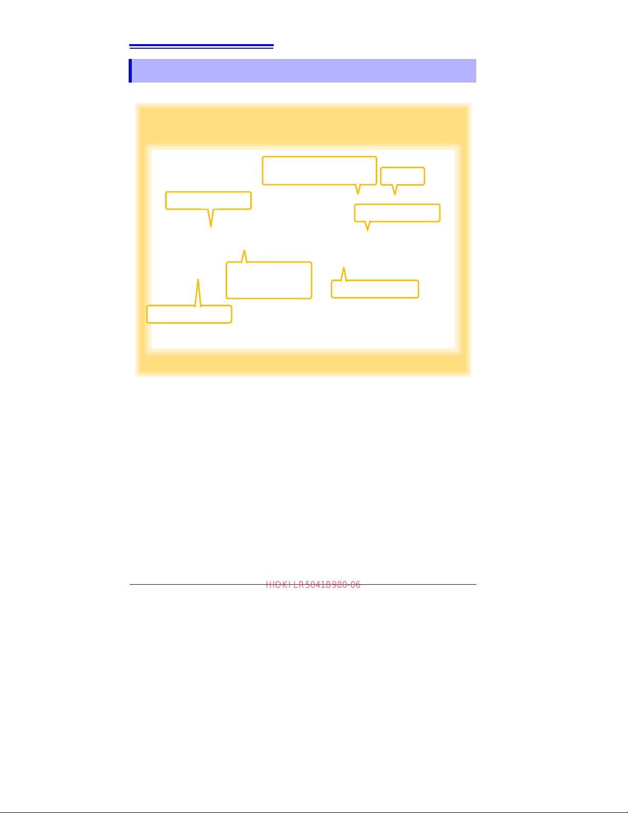
76
Select the drive.
2
Select the folder.
3
Select the file.
(Up to 100 can
be selected.)
4
Select the drive.
5
Select [Copying Data]
or [Moving Data].
1
7
Click
Select the folder.
6
Example: Copy a file from the folder C:\Users\hioki\Documents\LR5000
to C:\Users\hioki\Desktop.
HIOKI LR5041B980-06
6.1 Copying and Moving Data
6.1 Copying and Moving Data
The selected logger recording files can be copied or moved to any folder.
Find Quality Products Online at: [email protected]
www.GlobalTestSupply.com
Page 81
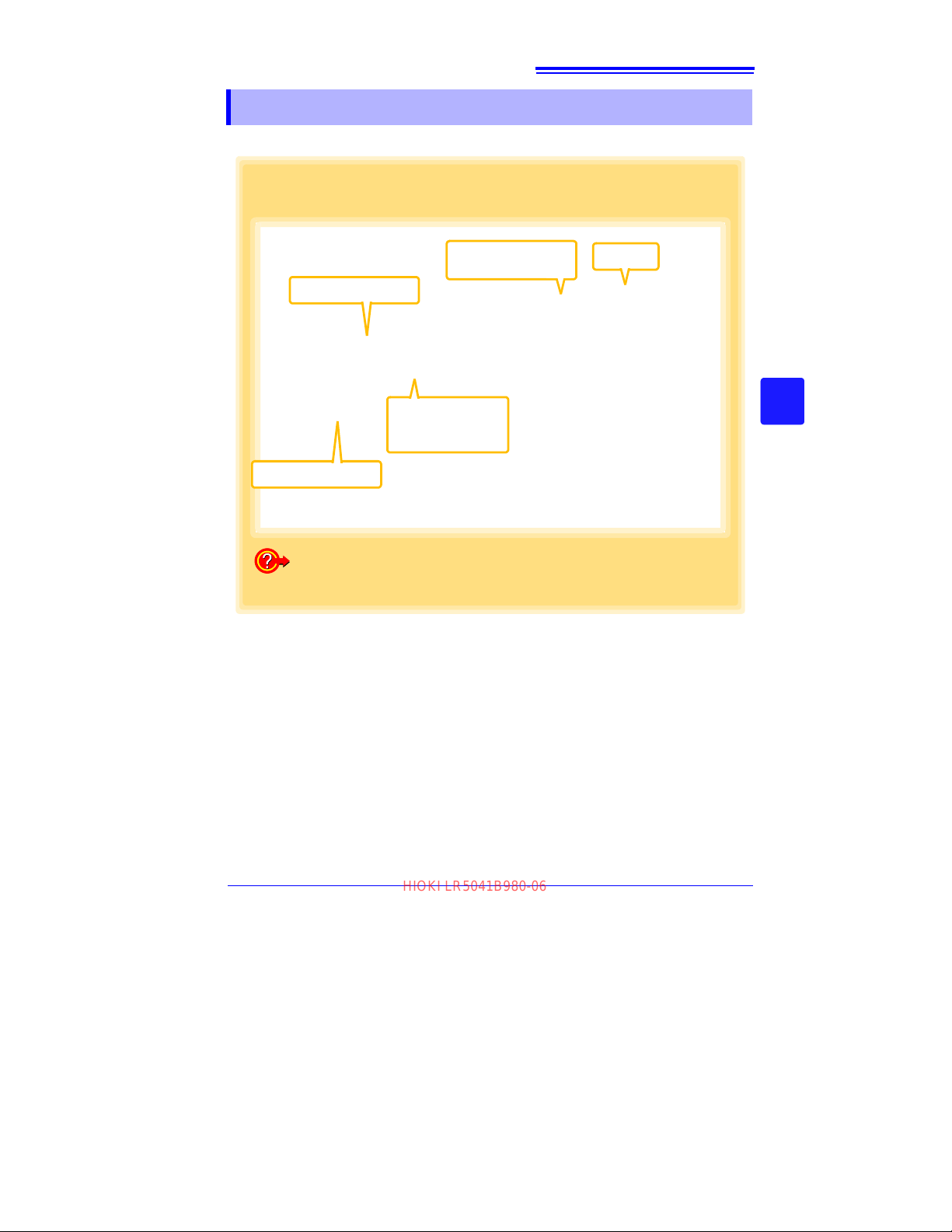
6.2 Deleting Data
Select the drive.
2
Select the folder.
3
Select the file.
(Up to 100 can
be selected.)
4
Select
[Deleting Data].
1
5
Click
Example: Delete a file from the folder C:\Users\hioki\Documents\LR5000.
How can I delete data from the logger's memory?
See: "Delete Data" (p.42)
HIOKI LR5041B980-06
Select and delete logger recording files as follows.
77
6.2 Deleting Data
3
6
Chapter 6 Organizing Data
Find Quality Products Online at: [email protected]
www.GlobalTestSupply.com
Page 82
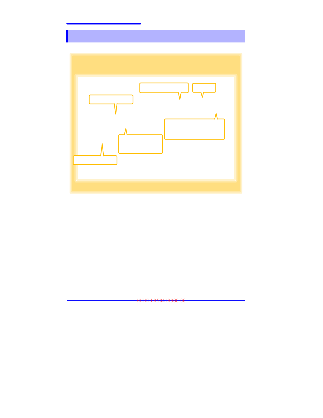
78
Select the drive.
2
Select the folder.
3
Select the file.
(Up to 10 can be
selected.)
4
Select [Combining
Data].
1
6
Click
Click to specify the destination and file name for
the combined data file.
5
Example: Combine file 20110117 with other files in C:\Users\hioki\Docu-
ments/LR5000, and save the combined data file in C:\Users\hioki/
Desktop.
HIOKI LR5041B980-06
6.3 Combining Data
6.3 Combining Data
Separate logger recording files can be combined into one set of recording data.
Find Quality Products Online at: [email protected]
www.GlobalTestSupply.com
Page 83
79
Select the drive.
2
Select the folder.
3
Select [Extracting Data].
1
7
Click
Click to specify the destination
and file name for the extracted
data file.
6
Example: Extract the data of January 25th from the file 20110117, and save
to a different file.
Specify the extracting time span
and extracted data (model).
5
Select the file.
(one only)
4
HIOKI LR5041B980-06
6.4 Extracting Data
6.4 Extracting Data
Data in a logger recording file can be extracted to a specified time span and saved
with a different file name.
3
6
Chapter 6 Organizing Data
Find Quality Products Online at: [email protected]
www.GlobalTestSupply.com
Page 84
Options Settings (LR5000 Util-
1
If the LR5000 Utility Program is not running on the computer, click the icon in the
task tray (notification area), and click
[Option].
The Options screen appears.
2
Change the settings as needed.
See: "7.1 Changing the Sav ing Method
for Imported Data" (p.82)
"7.2 Changing the Connection
Monitoring Method, and Logger Settings Displays" (p.83)
3
Click the [Save] button.
Returns to the
main screen.
3
2
Click
Click
Note: If the LR5000 Utility Program is
running, click
[Option] on the
main screen.
HIOKI LR5041B980-06
81
ity Program)
These settings determine the saving method for imported logger data, device connection monitoring, and logger setting display functions.
Chapter 7
3
7
Chapter 7 Options Settings (LR5000 Utility Program)
Select the [Automatically import and store data when the logger is connected to a
computer] checkbox and clear the [Always specify folder and file before importing]
check box to display the Data Import screen (p.60).
Find Quality Products Online at: [email protected]
www.GlobalTestSupply.com
Page 85
82
Click the [Import Method] tab.
1
Click to specify the save destination folder.
2
If you select the check box,
select the folder name.
3
How can the save destination folder be changed?
How can the file naming method be changed?
File names can be specified as a combination of up to three of these components:
model name, model comment, serial no., recording start day, recording start date and
time, and save day
Set Auto Import and Auto Graph
Display functions, if desired.
See:
"4.5" (p.49)
HIOKI LR5041B980-06
7.1 Changing the Saving Method for Imported Data
7.1 Changing the Saving Method for Imported Data
The saving method for imported logger data can be changed as follows.
Find Quality Products Online at: [email protected]
www.GlobalTestSupply.com
Page 86
83
Task tray (notification area) icon (p.59)
Click the [Details] tab.
When cleared, the Communication
Utility program has to be started
manually.
How can the device connection monitoring setting be changed?
When [Monitor COM port] is
selected, specify the COM port
to monitor.
How can the function settings of the logger's settings displays be
changed?
Show the settings of the [Save Settings] and
[Open Settings] buttons. (p.42)
HIOKI LR5041B980-06
7.2 Changing the Connection Monitoring Method, and Logger Settings Displays
7.2 Changing the Connection Monitoring
Method, and Logger Settings Displays
Change the device connection monitoring settings and the fun ctions on t he logger
settings displays as follows.
3
7
Chapter 7 Options Settings (LR5000 Utility Program)
Find Quality Products Online at: [email protected]
www.GlobalTestSupply.com
Page 87
8.1 Measurement Specifications
HIOKI LR5041B980-06
Specifications Chapter 8
8.1 Measurement Specifications
Input DC voltage (1 channel)
LR5041: 4 MΩ±10%
Input impedance
Measurement ranges
Measurement accuracy ±0.5%rdg. ±5dgt.
Accuracy guarantee for
temperature and humidity
Temperature coefficient
Guaranteed
accuracy period
Product warranty period 3 years
Maximum ratings
LR5042: 2.2 MΩ±10%
LR5043: 2 MΩ
±50.00 mV (LR5041)
±5.000 V (LR5042)
±50.00 V (LR5043)
"UF" or "OF" indicates out-of-range measurement
• Temperature: 23°C±5°C (73°F±9°F)
• Humidity: 80%RH or less (non-condensating)
Measurement accuracy × 0.05/°C
Note: Add to measurement accuracy when outside of th
23°C±5°C (73°F±9°
1 year
Max. rated voltage between terminals:
±60 mV (LR5041), ±6 V (LR5042), ±60 V (LR5043)
Max. rated voltage to ground:
60 V DC
±10%
F)
85
3
e range
8
Chapter 8 Specifications
Find Quality Products Online at: [email protected]
www.GlobalTestSupply.com
Page 88

86
HIOKI LR5041B980-06
8.2 Functional Specifications
8.2 Functional Specifications
Display type LCD
Measured value, units (mV, V), recording (REC), endless recording
(ENDLESS), statistical recording (STAT), recording interval (INTVL),
Display contents
Operation button Four ("SET", "REC/STOP", "+", "-")
Recording interval 1/2/5/10/15/20/30 sec., 1/2/5/10/15/20/30/60 min.
Recording modes
Recording capacity
Recording start method
Recording stop method
Retained recording sessions
Alarm
Scaling
Preheat output OFF/0.5/1/2/5/10/30/60 sec.
Power save setting
Real-time clock Provided
pre-heat time (PrE.H), date and time (TIME), alarm (AL), battery status,
recorded data count (DATA), maximum value (MAX), minimum value
(MIN), auto power saving (APS)
• Instantaneous recording: The instantaneous value is recorded at each
recording interval
• Statistical recording:
Measurements are taken once per seco
mum, minimum, and average values are saved at each recording interval (cannot be selected when the recording interval is set to one
second).
• Instantaneous recording: 60,000 values
• Statistical recording:
15,000 instantaneous, maximum, minimum, and average values
• Logger button operation
• Instant or scheduled time (set by computer/Data Collector)
• Logger button operation (endless recording)
• Logger button operation (one-time recording)
• Scheduled time (endless recording)
• Scheduled time (one-time recording)
Scheduled time is set by computer/Data Collector
Two sessions (each from recording start to stop)
Indicates when measured values are outside of the range defined by
upper and lower thresholds set from a computer or the Data Collector
Scales and displays measured values according to settings made from a
computer or the Data Collector (measurement units are not displayed for
scaled values)
The measurement data display turns off about 30 seconds after the last
button operation (cancel power save for continuous display)
nd, and insta
ntaneous, maxi-
Find Quality Products Online at: [email protected]
www.GlobalTestSupply.com
Page 89
8.3 Miscellaneous
HIOKI LR5041B980-06
8.3 Miscellaneous
Clock accuracy ±50ppm (@25°C (@77°F)) ±4.32 s/day
Backup Recorded data and settings (independent of battery)
Interface
Power supply
Maximum rated power 0.1 VA
Battery life
Dimensions Approx. 79W×57H×28D mm (3.11"W×2.24"H×1.10"D)
Mass Approx. 105 g (3.7 oz.) (w/battery)
Dust and water
protection rating
Accessories
Options
Environmental conditions
Applicable Standards
Half-duplex start/stop synchronous infrared serial communication
between the logger and Communication Adapter or Data Collector
• Rated supply voltage: 1.5 V DC
• One AA-size alkaline battery (LR6)
• Recording and clock operation, and maximum and mi nimum values
are retained for about 30 seconds during battery replacement
• Approx. 2 year (instantaneous recording, with 1-minute recording interval and auto power saving, @20°C (
•Approx. 2 mo
IP54 (EN60529) (with connection cable connected, but not including
cable tip)
• LR6 alkaline battery ...................................... 1 (Internal in the lo gger)
• LR9802 Connection Cable ........................... 1
• Instructi
• Operation Manual..........................................
• Stand............................................................. 1
• LR5091 Communication Adapter
• LR5092-20 Data Collector
• LR9802 Connection Cable
• LR9901 Wall-Mounted Holder
• Z5004 Magnetic Strap
• Operating environment: indoors, pollution degree 2, up to 2000 m ASL
• Operating temperature and hu midity: -20°C to 70°C (-68°F to 158°F),
80%RH or l
• Storage temperature and humidity: -20°C to 70°C (-68°F to 158°F)
80%RH or less (non-condensating)
• Safety: EN61010
• EMC : EN61326
nth (with 1-second recording interval, @20°C (@68°F)
on Manual.........................................1
ess (non-condensating)
@68°F))
1
87
3
)
8
Chapter 8 Specifications
,
Find Quality Products Online at: [email protected]
www.GlobalTestSupply.com
Page 90

88
HIOKI LR5041B980-06
8.4 LR5091 Communication Adapter Specifications
8.4 LR5091 Communication Adapter Specifications
Main Unit General Specifications
Functions
Compatible loggers
Operating temperature
and humidity
Storage temperature and
humidity
Operating environment Indoors, pollution degree 2, up to 2000 m ASL
Power supply DC5 V (USB bus-powered)
Maximum rated power 0.5 VA
Dimensions
Mass Approx. 43 g (1.5 oz.) (without USB cable)
Applicable Standards
Product warranty period 3 years
Converts between the logger's infrared signals and US B signals to sup port communications between the logger and a computer (USB port).
LR5001 Humidity Logger, LR5011 Temperature Logger, LR5 031 Instrumentation Logger, LR5041, LR5042, LR5043 Voltage Logger, LR5051
p Logger
Clam
Note: Communication with models LR5031 is supported by PC Utility
ve
rsion 1.05 and later.
LR5051 is supported by PC Utility version 1.01 and later.
Temperature: 0°C to 40°C (32°F to 104°F), Humidity: 80%RH or less
(non-condensating)
Temperature: -10°C to 50°C (14°F to 122°F), Humidity: 80%RH or less
(non-condensating)
Approx. 83W×61H×19D mm (3.27"W×2.40"H×0.75"D) (without projections)
• Safety: EN61010
• EMC : EN61326
USB standard USB 2.0 compliant, Full Speed support
Connector Mini B series re ceptacl e
Connectable device Computer
Communication speed 115,200bps
Communication method Half-duplex start/stop synchronous infrared serial communication
Communication speed 115,200bps
Accessories
USB cable (1 m) ........................................................1
LR5000 Utility Program (CD) ....................................1
Find Quality Products Online at: [email protected]
www.GlobalTestSupply.com
Page 91
8.4 LR5091 Communication Adapter Specifications
HIOKI LR5041B980-06
Supplied LR5000 Utility Program Specifications
Supplied medium CD....................................1
Personal computer meeting the following specifications
• CPU: 1 GHz or faster processor clock
• RAM: 1 GB or more (32-bit), 2 GB or more (64-bit)
Operating environment
Model
communication support
Communication
connections
Setting functions
Auto-start function
• Operating system: Windows 7 or Windows 10
• Library: .NET Framework 4.5.2 or later
• Interface: USB (or COM port for models 3910, 3911, or 9612)
• Monitor resolution: 1024 x 768 or higher
• Hard disk: At least 30 MB free space
(Additional space is required for storing recorded data.)
All LR5000-series loggers
Note1: Communication with models LR
version 1.05 and later.
LR5051 is supported by PC Utility version 1.01 and later.
Note2: The COMMUNICATION UTILITY program supports the following
mode
ls' settings a
port and 9612 RS-232C cable are required when using the
model 3910 or 3911 Communication Base.
• All "Data Logger" models 363x to 364x
• Communication Base models 3910, 3911, and 3912
Communication with LR5000-series loggers:
• Computer, USB cable, LR5091 Communication Adapter, and LR5000series logger
•
Computer, USB cable, LR5092-20 Data Collector, and LR5000-series
logger
mmunication with the LR5092-20 Data Collector:
Co
Computer, USB cable, and LR5092-20 Data Collector
• Export/import settings by communication with the LR5000 series
• Settings exported from each LR5000 are stored
(the following functions are supported by the supplie d P
2.00, or later)
• Export/import settings by communication using the LR5092-20 Data
tor
Collec
• Import and save logger settings using the LR5092-20 Data Collector
via comm
• Settings exported to the LR5092-20 Data Collector are stored on the
computer
A small resident program (icon in the task tray/notification area) detects
when a logger or the Data Collector i s connected to the computer, and
automatically starts the LR5000 Utility Progra m.
unication or SD memory card
nd data import functions. A computer COM
503
1 is su
pported by P
on the computer
89
3
C Utility
8
Chapter 8 Specifications
C Utility version
Find Quality Products Online at: [email protected]
www.GlobalTestSupply.com
Page 92

90
HIOKI LR5041B980-06
8.4 LR5091 Communication Adapter Specifications
• Communicates with the LR5000-series loggers, and i mports recorded
data
• Combines recorded data
• Incorporates new data when an LR
Data import functions
Graph display functions
Data list display functions
Export functions
Import functions
Printing functions
Data processing
functions
File management
functions
Help function Displays helpful operating instructions
previously imported
(the following functions are supported by the supplied PC Utility version
2.00, or la
• Communicates with the LR5092-20 Data Collector, and imports
• Imports data saved to an SD memory card in the LR5092-20 Data Col-
• Displays up to 16 channels in a graph
• Displays up to 16 Y-axes
• Displays one time base axis
• Set line colors for each channel, and display/hide lines and bar graphs
• Auto setting of time base and vertical axis
• Display/hide Y-axis grid lines, and set grid display density
• Select display background color
• Copy graph images to the clipboard
• A/B cursor functions
• Displays statistical data (maximum, minimum, and average)
• Browse recorded data in tabular format
• Displays up to 600 channels
• Displays statistical data (maximum, minimum, and average)
• Export all recorded data displayed in a table in CSV format
• Paste to Excel
• Export all recorded data between A/B cursors in CSV format
• Paste to Excel
Import text files from the 3169 Clamp-On Power HiTester
Note: Only electric energy data recorded at one-second or longer interval
can be imported
• Prints graphs and statistical data
• Supports A3, A4, and B4 paper sizes
Scaling (y=a×x+b), electric power calculation, energy cost calculation,
operating rate calculation, integration, dew-point temperature calculation, arithmetic calculations, out-of-range data revision
• Copy and delete data saved on the computer
(the following functions are supported by the supplied PC Utility version
2.00, or la
• Delete data saved to an SD memory c ard in the LR509 2-20 Data Col -
ter)
recorded data
lector
fo
r each c
hannel
ter)
lector
saved in the Data Collector
®
all recorded data displayed in a data table
®
all recorded data between A/B cursors
5000-series
logger holds data not
Find Quality Products Online at: [email protected]
www.GlobalTestSupply.com
Page 93
Maintenance and
HIOKI LR5041B980-06
91
Service
Chapter 9
Requesting repairs
• Use the original packing materials when transporting the instrument, if possible.
• Pack the instrument so that it will not sustain damage during shipping, and include a
description of existing damage. We do not take any responsibility for damage
incurred during shipping.
• Please contact your dealer or Hioki representative for information on where to submit products for repair.
When the logger will not be used for long time
To avoid corrosion and damage to this instrument from battery leakage,
remove the batteries from the instrument if it is to be stored for a long
time (1 week).
Replaceable part and service life
A part used in the instrument is characterized by performance that degrades over
years of use. It is recomm
functionality over the long term. To order a replacement, please contact your Hioki
distributor. Part service life varies with the operating environment and frequency of
use.
Part Service life
Electric double-layer
capacitor
ended to replace this part regularly to ensure instrument
The instrument uses an electric double-layer capacitor to back up internal components, including the clock.
Even if it takes only a short time (about 30 s or less) to replace the batteries, the internal clock may not be backed up, with the result that all
segments of the screen ma
ed. In this case, the life of the capacitor has expired.
Especially in high-temperature environment
may be significantly shortened.
y be displayed when the instrument is start-
s, the
life of the capacitor
3
9
Chapter 9 Maintenance and Service
Find Quality Products Online at: [email protected]
www.GlobalTestSupply.com
Page 94
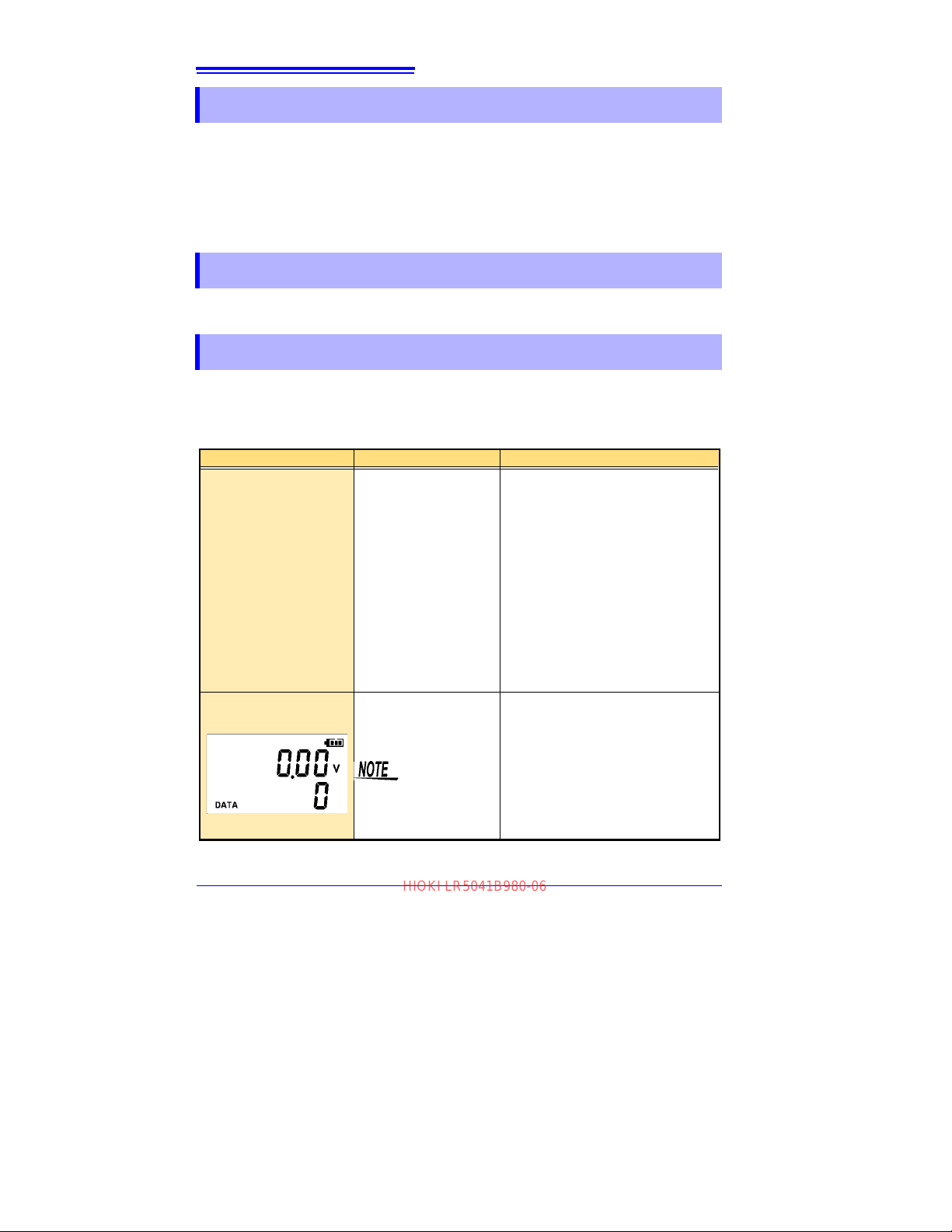
92
HIOKI LR5041B980-06
9.1 Cleaning
9.1 Cleaning
Wipe the LCD gently with a soft, dry cloth.
To clean the instrument, wipe it gently with a soft cloth moistened with water or
mild detergent.
IMPORTANT
Never use solvents such as benzene, alcohol, acetone, ether, ketones, thinners or
gasoline, as they can deform and discolor the case.
9.2 Disposing of the Logger
Obey local regulations for disposal of electronic equipment.
9.3 Troubleshooting
If damage is suspected, check the "Before requesting repairs" section before contacting your dealer or Hioki representative.
Before requesting repairs
Problem Symptom Probable Causes Remedies and References
The LR5000 Utility Program
cannot be installed.
No measured value is displayed.
(LR5043 Example)
• The computer operating
environment may be
incompatible.
• The installation procedure may be incorrect.
The connection cable plug
is not inserted all the way
in.
The maximum and minimum values are not displayed when the recorded
data count is 0.
Check the operating environment requirements, and try installing in (another) compatible computer.
See: "LR5000 Utility Program Operating
Requirements" (p.23)
Refer to the installation procedure, and try
again.
Pay particular attention to the following:
• Be sure to log in with an Administrator
account.
• Before installing, be sure to close any
applications running on the computer.
• If the installation screen does not appear,
execute X:\English\Setup.exe.
See: "Installation Procedure" (p.23)
Verify the correct plug orientation, and insert
it as far as possible.
If the values are not displayed despite these
measures, the connection cable and logger
need to be inspected and repaired.
Please contact your dealer or Hioki representative.
See: "Requesting repairs" (p.91)
Find Quality Products Online at: [email protected]
www.GlobalTestSupply.com
Page 95
9.3 Troubleshooting
HIOKI LR5041B980-06
Before requesting repairs
Problem Symptom Probable Causes Remedies and References
The display is blank. Power save is enabled.
The battery is depleted too
quickly.
Logger settings cannot be
changed.
How can the logger's memory be erased?
How can recorded values
be reorganized?
Recorded data has disappeared.
• The battery supplied
with the logger is still
being used.
• A zinc-manganese battery is being used.
Dead battery.
−
−
Recording was restarted
after stopping.
Press any button or send a communication
signal to turn on the display.
See: "Part Names/Functions and Display
Indicators" (p.12)
Install a new AA-size (LR6) alkaline battery.
See: "2.1 Installing (or Replacing) the Bat-
tery" (p.17)
When the battery indicator appears, settings cannot be changed (but only displayed). Replace the battery.
See: "2.1 Installing (or Replacing) the Bat-
tery" (p.17)
Logger memory can be erased using the
LR5000 Utility Program.
See: "Other Settings on the Logger Set-
tings Screen" (p.42)
Note that data recorded prior to the last recording is automatically erased whenever recording starts.
(The logger retains the data from both current
and most recent prior recording operation.)
See: "4.3 Starting and Stopping Record-
ing" (p.46)
Enable scaling.
See: "5.1 Scaling" (p.67)
Scaling settings can be made before recording.
See: "Scaling (set as needed)" (p.40)
Note that if recording is accidentally restarted after stopping, data recorded prior to the
last recording is automatically erased. (The
logger retains the data from both current and
most recent prior recording operations.)
93
3
9
Chapter 9 Maintenance and Service
Find Quality Products Online at: [email protected]
www.GlobalTestSupply.com
Page 96
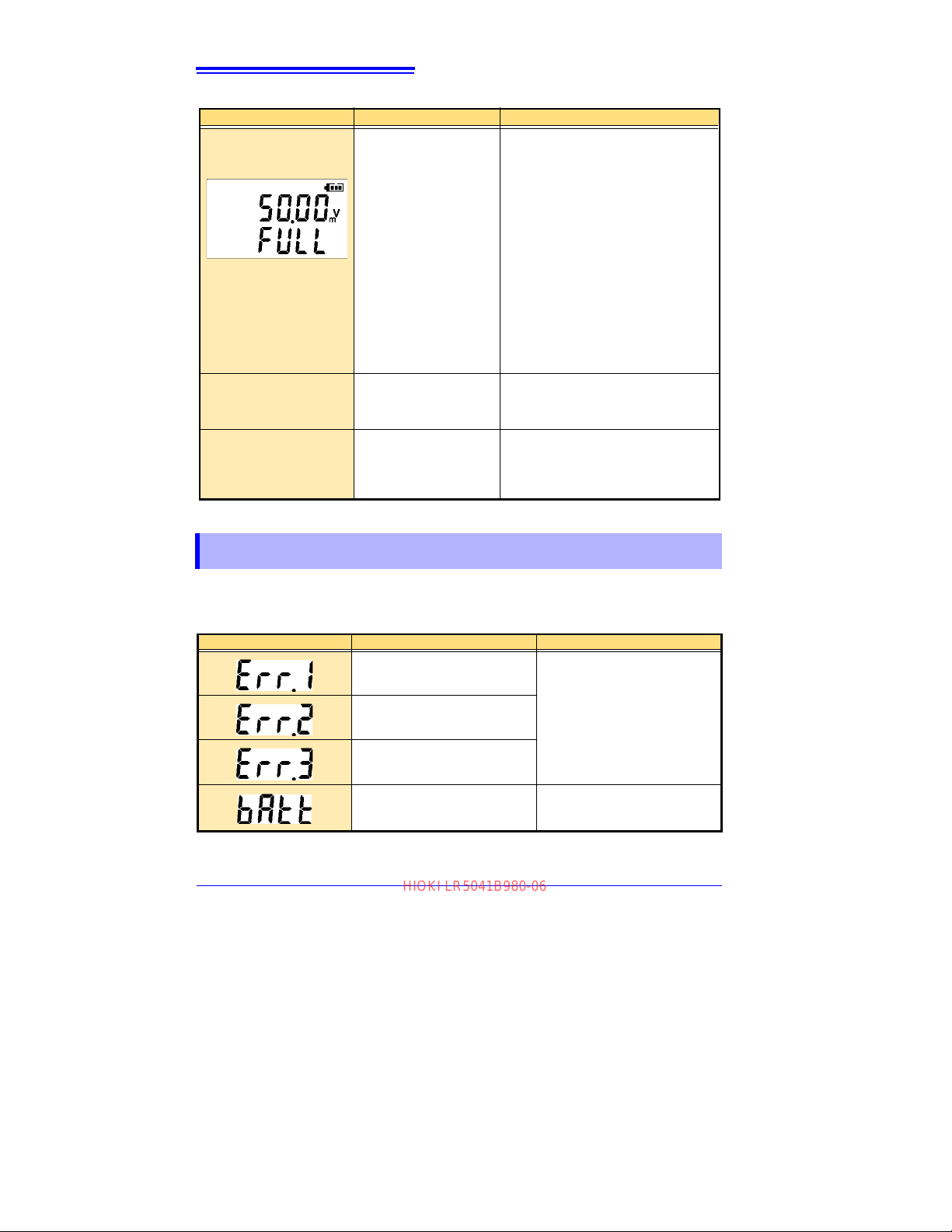
94
HIOKI LR5041B980-06
9.4 Error Displays
Before requesting repairs
Problem Symptom Probable Causes Remedies and References
The [REC] indicator disappears even though recording has not been stopped.
The logger cannot communicate with the new LR5091
(LR5092).
The [Failed to read data par-
tially.]
message appears.
The one-time recording
stop method is selected.
The installation of the
device driver to the
LR5091 (LR5092) failed.
The instrument can display up to 84000 data sets
per measurement parameter.
With one-time recording, recording stops automatically when memory becomes full.
Change the stop method to endless recording.
See: Making Settings on the Logger:"Stop
Method Setting (for when memory
becomes full)" (p.33)
See: Making Settings from the LR5000
Utility Program:"Stop Method" (p.39)
(With endless recording, the oldest data is
overwritten when memory is full, so be sure to
save data to a computer periodically during
long-term recording. Data can be saved to a
computer without stopping recor ding .)
See: "4.5 Automatically Importing (Saving)
Recorded Data to a Computer, and
Graph Display" (p.49)
For Window XP, the driver may be required
to be installed to each LR5091 (LR5092).
Open Windows Device Manager and re-install the driver.
The LR5000 viewer places a limit on
the number of data sets displayed on
graphs and tables.
Change the duration to be displayed.
Change from [All Data]
to [1day].
9.4 Error Displays
The display appears as follows when an error occurs on the logger.
Logger Error Displays
Error Displays Meaning Remedies and References
Calibration data error:
A fault occurred with the internal
calibration data
Microcomputer error:
A fault occurred in microcomputer
ROM/RAM.
Data recording error:
A fault occurred in recording data
or accessing settings.
Battery voltage is too low for normal logger operation.
.
Inspection and repair is required.
Please contact your dealer or Hioki
representative.
equesting repairs" (p.91)
See: "R
Replace the battery.
See: "2.1 Installing (or Replacing)
the Battery" (p.17)
Find Quality Products Online at: [email protected]
www.GlobalTestSupply.com
Page 97
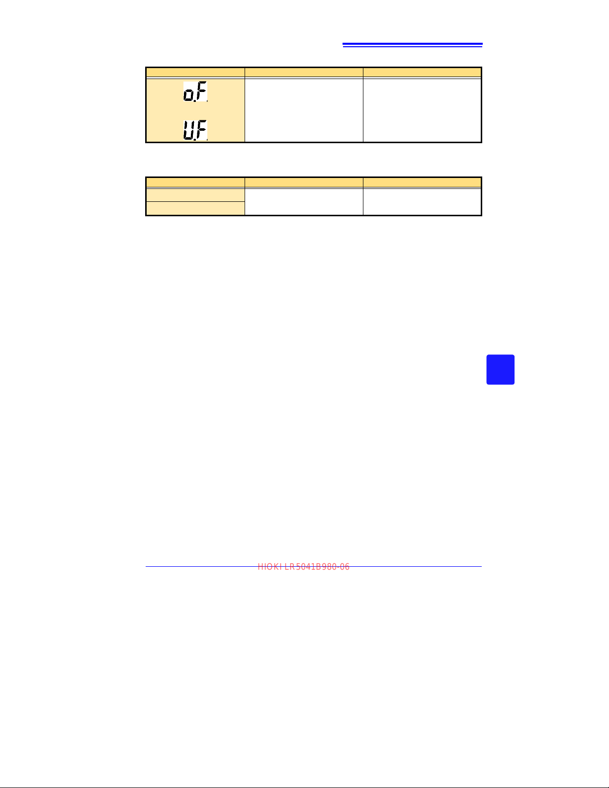
9.4 Error Displays
HIOKI LR5041B980-06
Logger Error Displays
Error Displays Meaning Remedies and References
Out-of-range values cannot be displayed.
[OF] or [UF] is displayed when this
or
A measured value is out of range.
data is imported by the LR5000 Utility
Program.
95
LR5000 Utility Program Error Displays
Error Displays Meaning Remedies and References
OF
UF
A measured value is out of range.
Out-of-range values cannot be displayed.
3
9
Chapter 9 Maintenance and Service
Find Quality Products Online at: [email protected]
www.GlobalTestSupply.com
Page 98
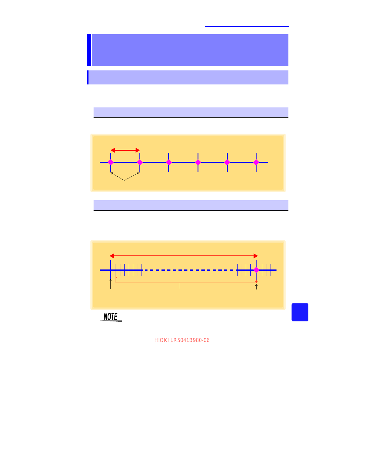
A1
Recording Interval
Instantaneous values are recorded
Recording Interval
(example: 1 min.)
10:01:00
Instantaneous values
are recorded
10:00:00
Recording
Start
10:00:01 to 10:01:00 (measures once per second)
Maximum, minimum, and average values over this
time span are recorded.
HIOKI LR5041B980-06
Appendix 1 About Recording Modes
Appendix
Appendix 1 About Recording Modes
The recording method depends on the selected recording mode. The recording
modes are as follows.
Instantaneous Recording
Measurements are recorded in internal memory at each recording interval.
3
Statistical Recording
Measurements a
and average values are saved to internal memory at each recording interval.
Data at the recording start time is not recorded (in the following case, data at 10:00:00
is not recorded).
re taken once per second, and instantaneous, maximum, minimum,
Statistical recording cannot be selected when the recording interval is
set to one second.
Appendix
Find Quality Products Online at: [email protected]
www.GlobalTestSupply.com
Page 99
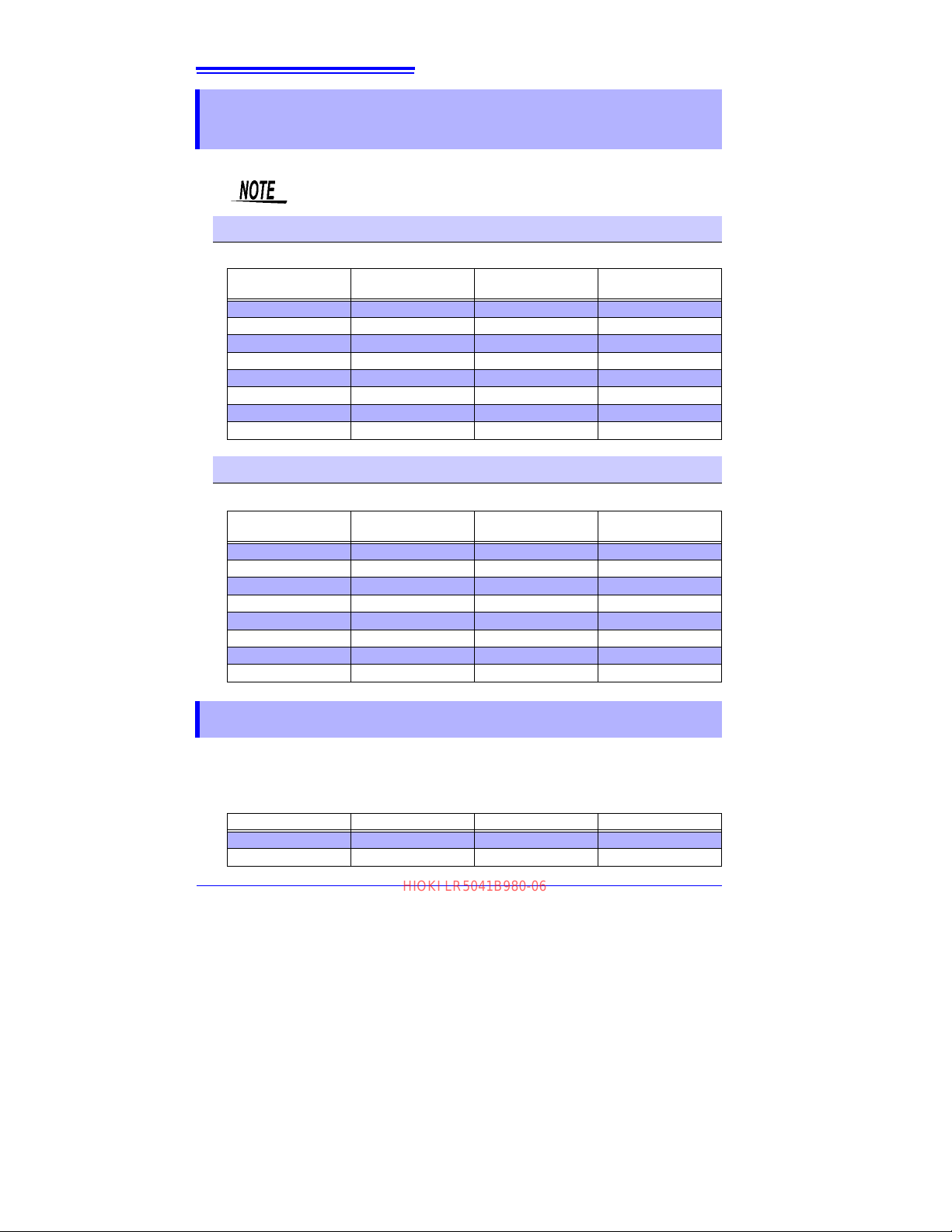
A2
HIOKI LR5041B980-06
Appendix 2 Recording Intervals and Maximum Recording Times
Appendix 2 Recording Intervals and Maximum
Recording Times
The maximum recording time is calculated according to the recording capacity.
The maximum recording time is limited by the remaining battery capacity.
Instantaneous Recording
Up to 60,000 values can be recorded.
Recording Interval
1 sec. 16 h, 40 min 1 min 41 d, 16 h
2 sec. 1 d, 9 h, 20 min 2 min 83 d, 8 h
5 sec. 3 d, 11 h, 20 min 5 min 208 d, 8 h
10 sec. 6 d, 22 h, 40 min 10 min 416 d, 16 h
15 sec. 10 d, 10 h 15 min 625 d
20 sec. 13 d, 21 h, 20 min 20 min 833 d, 8 h
30 sec. 20 d, 20 h 30 min 1250 d
Maximum Recording
Statistical Recording
Time
Recording Interval
60 min 2500 d
Maximum Recording
Time
Up to 15,000 values can be recorded.
Recording Interval
1 sec. (Cannot be set) - 1 min 10 d, 10 h
2 sec. 8 h, 20 min 2 min 20 d, 20 h
5 sec. 20 h, 50 min 5 min 52 d, 2 h
10 sec. 1 d, 17 h, 40 min 10 min 104 d, 4 h
15 sec. 2 d, 14 h, 30 min 15 min 156 d, 6 h
20 sec. 3 d, 11 h, 20 min 20 min 208 d, 8 h
30 sec. 5 d, 5 h 30 min 312 d, 12 h
Maximum Recording
Time
Recording Interval
60 min 625 d
Maximum Recording
Time
Appendix 3 Battery Life Approximation
Battery life depends on the recording interval.
The following table shows battery life when power saving (p.34) is enabled. Battery
life is approximately two months when power saving is disabled or when the stat
tical recording mode is enabled.
Recording Interval Battery Life Recording Interval Battery Life
1 sec. Approx. 60 days 30 sec. Approx. 1.5 year
10 sec. Approx. 1 year 1 min or more Approx. 2 year
is-
Find Quality Products Online at: [email protected]
www.GlobalTestSupply.com
Page 100
Index
HIOKI LR5041B980-06
Index
Index
1
Symbols
(-) button ....................................................12
(+) button ...................................................12
A
AL indicator .........................................13, 41
Alarm thresholds .................................13, 41
APS ............................................................34
Auto graph display ....................................50
Auto import ..........................................50, 82
Auto power save .......................................12
B
Battery is depleted too quickly ................93
Battery life approximation ........................A2
Battery status indicator ......................13, 18
C
CD Handling ................................................7
Changing the saving method ..................82
Cleaning .....................................................92
Clock setting ..................................15, 32, 42
Combining .................................................78
Connect to the computer .........................36
Connection cable ......................................20
D
Damage .....................................................92
Data
Combine
Copy .......................................................76
Delete ...............................................42, 77
Extract ....................................................79
Move .......................................................76
Data import screen (PC application) ......59
DATA indicator ..........................................13
Data view screen (PC application) ...62, 65
Delete ...................................................42, 77
Device connection monitoring setting ....83
Dew-point temperature calculation .........72
Display graph automatically ....................61
.................................................78
Display indicators ..................................... 13
Display the graph ...............................61, 65
Display value refresh time ....................... 12
Displaying a graph of saved recording
data
............................................................ 62
Disposing .................................................. 92
E
Electric power calculations ..................... 68
ENDLESS indicator ........................... 13, 33
Endless recording .............................. 33, 39
Energy cost calculations ...................69, 70
Error displays ............................................ 94
Extracting .................................................. 79
F
Features ....................................................11
G
Graph display .....................................49, 62
Graph Settings .........................................54
H
How can past data be viewed? .............. 63
How can the displayed area be
magnified?
How can the file naming method
be changed?
How can the function settings of the
logger’s settings displays be changed?
How can the logger’s memory be
erased?
How can the save destination folder
be changed?
How can the settings from one logger
be copied to another?
How to switch from a setting display
to measurement display?
................................................ 53
............................................. 82
83
..................................................... 93
............................................. 82
..............................38
........................49
I
Importing recorded data to a computer .49
Index
Find Quality Products Online at: [email protected]
www.GlobalTestSupply.com
 Loading...