

Page 1
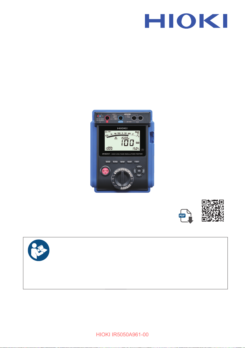
IR5050
HIOKI IR5050A961-00
IR5051
Instruction Manual
HIGH VOLTAGE
INSULATION TESTER
Safety Information
Part Names and Functions
Making Measurements
Apr. 2024 Edition 1
IR5050A961-00
Read carefully before use.
Keep for future reference.
p.13 Troubleshooting
p.20 Messages
p.37
The latest edition of the
instruction manual
[600665120]
p.115
p.117
EN
Page 2

HIOKI IR5050A961-00
Page 3
Contents
HIOKI IR5050A961-00
Introduction .......................................................................................... 7
Checking Package Contents ...............................................................8
Options (Sold Separately) ...................................................................9
Symbols and Abbreviations ............................................................... 11
Safety Information .............................................................................13
Precautions for Use ........................................................................... 15
1 Overview 17
1.1 Product Overview ............................................................17
1.2 Features .......................................................................... 19
1.3 Part Names and Functions .............................................20
2 Preparing for Measurement 27
2.1 Inserting/Replacing Battery ............................................. 27
2.2 Installing the Z3210 Wireless Adapter ............................31
2.3 Setting and Checking Date and Time .............................33
Setting date and time ............................................................... 33
Checking date and time ...........................................................34
2.4 Connecting Test Leads ...................................................35
3 Making Measurements 37
3.1 Measurement Procedure ................................................37
3.2 Pre-Operation Inspection ................................................ 38
3.3 Measuring Insulation Resistance .................................... 41
3.4 Automatic Discharge Function ........................................ 46
3.5 Filter Function .................................................................47
3.6 Use of GUARD Terminal ................................................. 48
3.7 Measuring Voltage ..........................................................50
3.8 Negative Voltage Notication Function (IR5051 Only) ....52
3.9 PV Insulation Resistance Measurement Function
IR5050A961-00
Retention of the measured value ............................................. 45
Measurement unaected by surface electrical resistance ....... 48
Measurement using G (GUARD) terminal grounding...............49
(IR5051 Only) .................................................................. 53
3
Page 4
Contents
HIOKI IR5050A961-00
4 Insulation Diagnosis Functions 59
4.1 TIMER Function (Timer Test) .......................................... 59
4.2 PI (Polarization Index) and DAR (Dielectric Absorption
Ratio) Measurement .......................................................61
4.3 SV Measurement (Step Voltage Test) ............................. 63
4.4 Ramp Measurement (Ramp Voltage Test) ...................... 66
4.5 DD Measurement (Dielectric Discharge) ........................68
4.6 Changing Settings for the Insulation Diagnosis
Functions ........................................................................70
5 Other Functions 71
5.1 Comparator Function ......................................................71
5.2 Automatic Power Save Function ..................................... 73
Recovering from the automatic power save state .................... 73
Disabling automatic power save function .................................73
5.3 Wireless Communications Function
(GENNECT Cross) ..........................................................74
5.4 Excel Direct Input Function (HID Function) .....................76
5.5 Version Upgrade Function .............................................78
5.6 Communicating with PC ..................................................79
5.7 Power On Options List .................................................... 82
6 Recording Measurement Data (Data Memory
Function) 85
6.1 Recording Measurement Data ........................................ 87
6.2 Checking Recorded Data ................................................ 90
6.3 Deleting Recorded Data ..................................................92
7 Specications 93
7.1 General Specications .................................................... 93
4
Manual recording (recording result of one measurement
session) .................................................................................... 87
Logging recording (recording at regular intervals) ................... 88
Deleting data with the selected number ................................... 92
Deleting all data .......................................................................92
Page 5
Contents
HIOKI IR5050A961-00
7.2 Input Specications, Output Specications, and
Measurement Specications ........................................... 95
Basic specications and accuracy specications ..................... 95
7.3 Insulation diagnosis functions ....................................... 101
7.4 Function Specications ................................................. 103
7.5 Specications of the Options ........................................ 110
Test leads ............................................................................... 110
Alligator clips .......................................................................... 111
Test pin set ............................................................................. 112
8 Maintenance and Service 113
8.1 Repair, Calibration, and Cleaning .................................113
Calibration .............................................................................. 113
Backing up your data ............................................................. 113
Cleaning ................................................................................. 114
Lithium battery........................................................................ 114
Test leads ............................................................................... 114
8.2 Troubleshooting ............................................................115
8.3 Messages ...................................................................... 117
8.4 System Reset ................................................................ 118
8.5 Disposing of the Instrument (Removal of Lithium
Battery) ......................................................................... 119
9 Appendix 121
9.1 Measurement Principles ...............................................121
9.2 Reproducibility of Insulation Resistance Measurement 122
9.3 Test Voltage Characteristic Graph ................................122
9.4 Example of PI (Polarization Index) Criteria ................... 123
9.5 Connecting the Insulation Resistance Tester to a Live
9.6 Properties of Insulating Materials ..................................124
9.7 Measurement Methods for Insulation Resistance of
Insulation resistance measurement .......................................121
PV insulation resistance measurement (IR5051 only) ........... 121
Line (Energized Parts) ..................................................123
PV Array ........................................................................ 125
Method with P-N open............................................................125
Method with P-N short-circuited ............................................. 126
5
Page 6

Contents
HIOKI IR5050A961-00
Index 127
WarrantyCerticate
6
Page 7
Introduction
HIOKI IR5050A961-00
Introduction
Thank you for choosing the Hioki IR5050/IR5051 High Voltage Insulation Tester. To
ensure you get the most out of this instrument over the long term, please read this
instruction manual carefully and keep it available for future reference.
Please review the separate Operating Precautions before using this instrument.
The IR5051 adds PV insulation resistance measurement functionality to the IR5050.
Product registration
Register your product in order to receive important product
information.
https://www.hioki.com/global/support/myhioki/registration/
Target audience of this instruction manual
This instruction manual has been written for use by individuals who use the product
or provide information about how to use the product. In explaining how to use the
product, it assumes electrical knowledge (equivalent of the knowledge possessed by
a graduate of an electrical program at a technical high school).
Trademarks
• Excel is a trademark of the Microsoft group of companies.
• The Bluetooth
SIG, Inc. and any use of such marks by Hioki E.E. Corporation is under license.
Other trademarks and trade names are those of their respective owners.
®
word mark and logos are registered trademarks owned by Bluetooth
7
Page 8
Checking Package Contents
HIOKI IR5050A961-00
Checking Package Contents
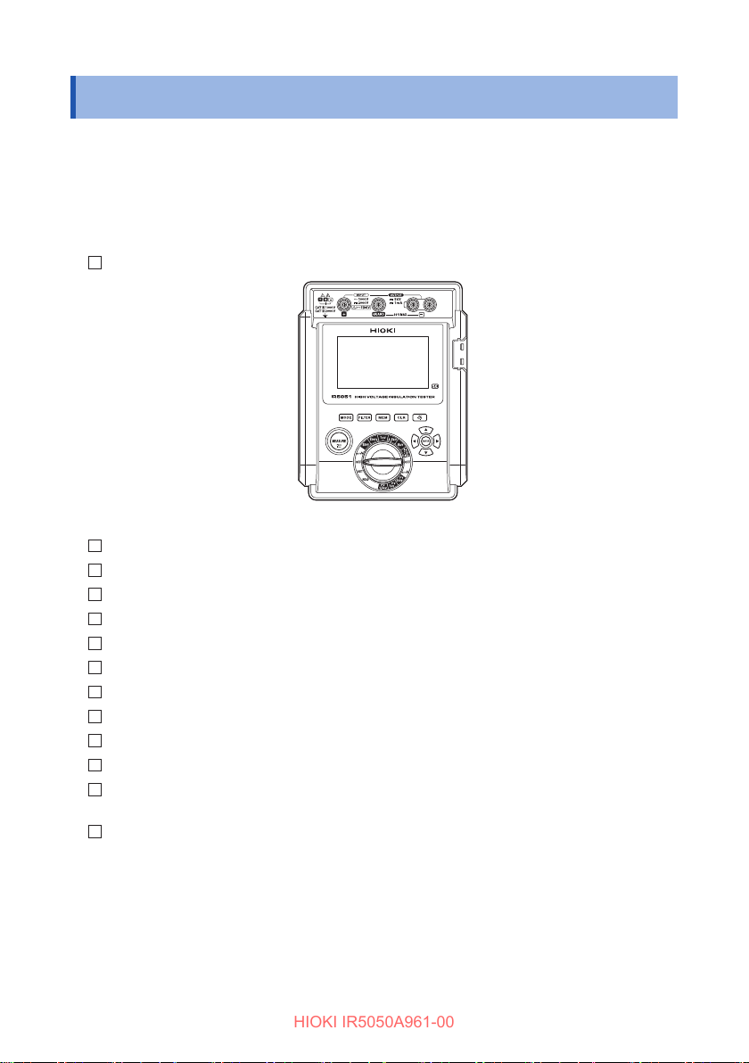
When you receive the product, inspect it for damage or anomaly. If you nd
any damage or discover that the product does not perform as indicated in the
specications, please contact your authorized Hioki distributor or reseller.
Check if the contents of the package are correct.
IR5050/IR5051 High Voltage Insulation Tester (in protector)
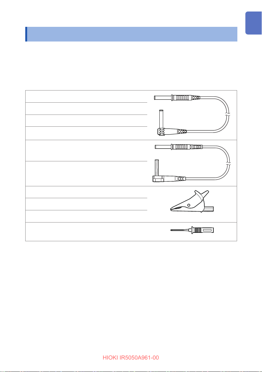
L9850-01 Test Lead Red, 3 m
L9850-02 Test Lead Black, 3 m, shielded cable
L9850-03 Test Lead Blue, 3 m
L9851-01 Alligator Clip Red, for L9850
L9851-02 Alligator Clip Black, for L9850
L9851-03 Alligator Clip Blue, for L9850
C0212 Carrying Case
LR6 Alkaline battery × 8 Installed in instrument
Instruction Manual (this manual)
Operating Precautions (0990A907)
L9852 Test Pin Set
(IR5051 and IR5051-90*1 only)
Z3210 Wireless Adapter (IR5051-90*1 only)
*1. Model IR5051-90 includes IR5051 and Z3210 as a set.
8
Red and black, for L9850
Page 9
Options (Sold Separately)
HIOKI IR5050A961-00
Options (Sold Separately)
The options listed below are available for the instrument. To purchase options, please
contact your authorized Hioki distributor or reseller. Options are subject to change
with no advance notice. Check Hioki’s website for the latest information.
Connection cables
L9850-01
L9850-11
L9850-03
L9850-13
L9850-02
L9850-12
L9851-01
L9851-02
L9851-03
L9852
Maximum rated line-to-ground voltage: 5000 V DC/2 mA (insulation resistance measurement),
Rated current: 4 A
Test Lead Red, 3 m
Test Lead Red, 10 m
Test Lead Blue, 3 m
Test Lead Blue, 10 m
Test Lead
Test Lead
Alligator Clip Red, for L9850
Alligator Clip Black, for L9850
Alligator Clip Blue, for L9850
Test Pin Set Red and black, for L9850
Black, 3 m, shielded
cable
Black, 10 m, shielded
cable
1000 V (Measurement category IV),
2000 V (Measurement category III)
9
Page 10
Options (Sold Separately)
HIOKI IR5050A961-00
Other
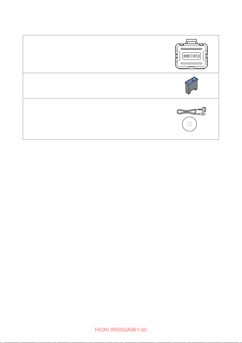
C0212 Carrying Case
Z3210 Wireless Adapter
For wireless communications
DT4900-01 Communication Package (USB)
With the DT4900-01, you can send data saved in the
instrument’s memory to a PC and change instrument
settings from a PC. Control of measurement is not
supported.
The application on the included CD is not used with
this instrument.
10
Page 11
Symbols and Abbreviations
HIOKI IR5050A961-00
Symbols and Abbreviations
Safety
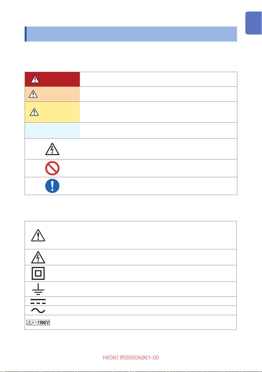
This manual classies seriousness of risks and hazard levels as described below.
DANGER
WARNING
CAUTION
IMPORTANT
Indicates an imminently hazardous situation that, if not avoided, will
result in death or serious injury.
Indicates a potentially hazardous situation that, if not avoided, could
result in death or serious injury.
Indicates a potentially hazardous situation that, if not avoided, could
result in minor or moderate injury or potential risks of damage to the
supported product (or to other property).
Indicates information or content particularly important for operating or
maintaining the product.
Indicates a high voltage hazard.
Failure to verify safety or improper handling of the product will lead to
an electric shock, a burn, an injury, or a death.
Indicates a prohibited action.
Indicates a mandatory action.
Symbols on the product
Indicates the presence of a potential hazard. See the “Precautions for Use”
(p. 15) and safety notes listed at the beginning of each operating instruction
in the instruction manual and the accompanying document entitled Operating
Precautions.
Indicates that dangerous voltage can be present at this terminal.
Indicates the product is protected throughout by double insulation or reinforced
insulation.
Indicates a grounding terminal.
Indicates that the product can be used for direct current (DC).
Indicates that the product can be used for alternating current (AC).
Indicates that the product must not be used with an AC distribution system that
exceeds 1100 V.
11
Page 12
Symbols and Abbreviations
HIOKI IR5050A961-00
Symbols for various standards
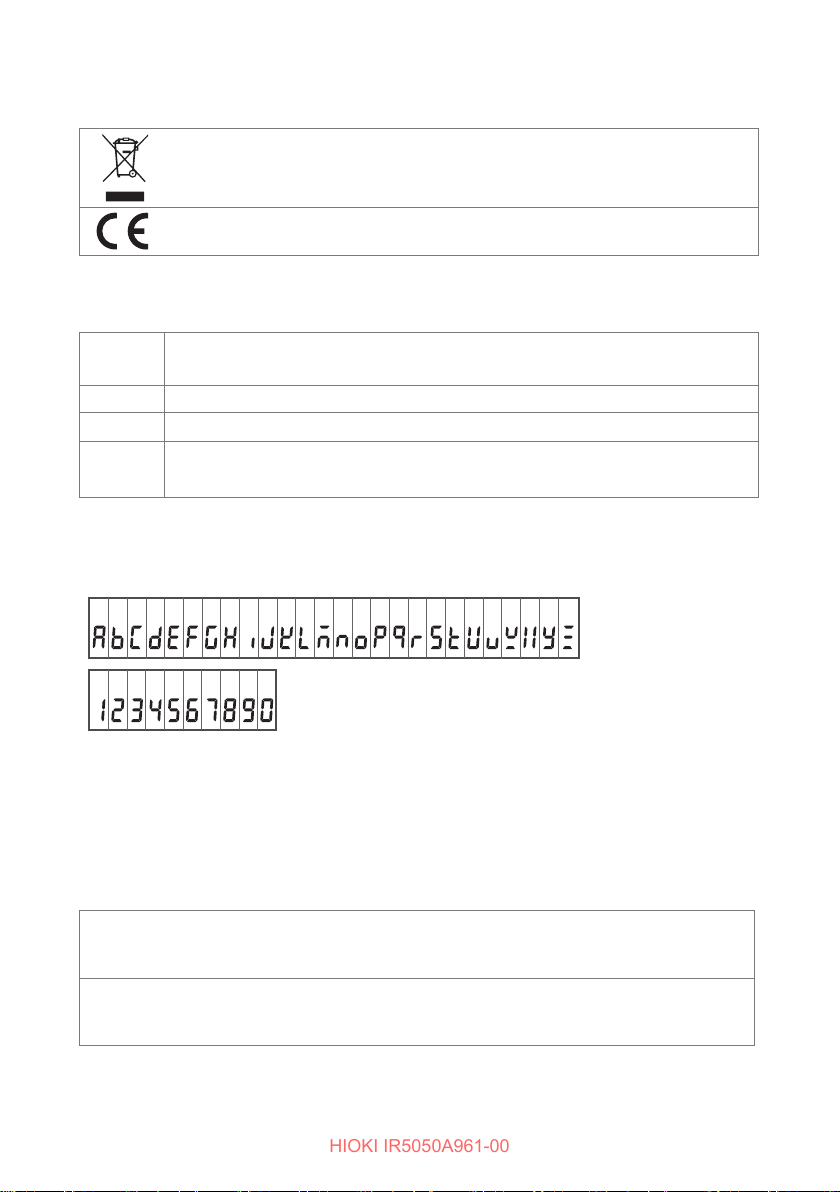
Indicates that the product is subject to the Directive on Waste Electrical and
Electronic Equipment (WEEE) in EU member nations. Dispose of the product by
local regulations.
Indicates that the product complies with standards imposed by EU directives.
Additional notation
Indicates additional information is presented below.
*
(p.) Indicates the page number to reference.
[ ]
MODE
(bold)
The names of user interface elements on the screen are enclosed in brackets ([ ]).
Indicates the names of the control keys.
Screen display
The instrument screen displays the alphanumeric characters as follows.
A B C D E F G H I J K L M N O P Q R S T U V W X Y Z
1 2 3 4 5 6 7 8 9 0
Accuracy labeling
The accuracy of the measuring instrument is expressed using a combination of the
formats shown below:
• By dening limit values for errors using the same units as measured values.
• By dening limit values for errors as a percentage of the reading and in terms of digits.
Reading
(displayed value)
Digit (resolution)
12
Indicates the value displayed by the measuring instrument. Limit values
for reading errors are expressed as a percentage of the reading (% of
reading or % rdg).
Indicates the minimum display unit (in other words, the smallest digit that
can have a value of one) for a digital measuring instrument. Limit values
for digit errors are expressed using digits (dgt).
Page 13
Safety Information
HIOKI IR5050A961-00
Safety Information
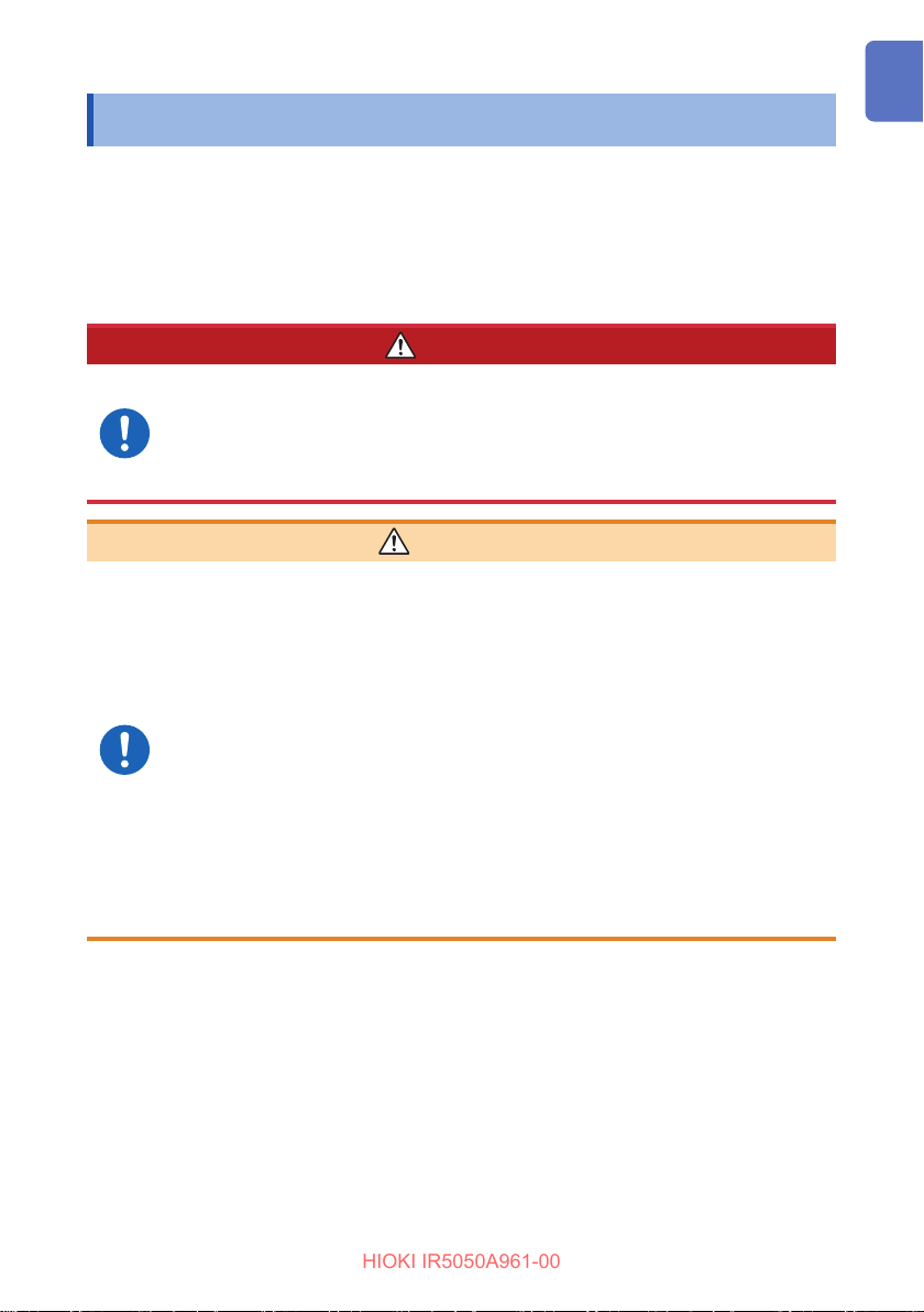
This instrument has been designed to conform to the international standard, IEC
61010, and thoroughly tested for safety before shipment. However, using the
instrument in a way not described in this instruction manual may negate the provided
safety features.
Carefully read the following safety notes before use.
DANGER
Familiarize yourself with the contents of this instruction
manual before use.
Otherwise, the instrument will be misused, resulting in serious bodily
injury or damage to the instrument.
WARNING
If you have not previously used electrical measuring
instruments, ensure adequate supervision by a technician
with experience in electrical measurement.
Failure to do so could cause the user to experience an electric shock.
It could also cause serious events such as heat generation, re, or arc
ash due to a short-circuit.
Wear electrically insulating personal protective equipment
(PPE) according to laws and regulations.
Performing measurement using this instrument involves live-line work.
Failure to wear PPE could cause the user to experience an electric
shock.
13
Page 14
Safety Information
HIOKI IR5050A961-00
Measurement categories
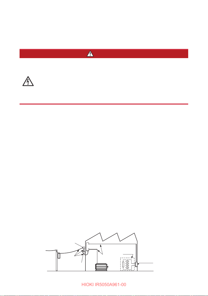
IEC 61010 denes measurement categories to facilitate safe use of measuring
instruments. Test and measurement circuits are classied into three categories
according to the type of mains to which they are intended to be connected.
DANGER
Do not use a measuring instrument and options with a lower
measurement category rating than that determined according
to the type of the mains for measurements on mains.
Do not use a measuring instrument and options without a
measurement category rating for measurements on mains.
Otherwise, the user will suer from a serious bodily injury or the
instrument and the mains installation will be damaged.
This product conforms to CAT III 2000 V and CAT IV 1000 V.
Measurement
category II
(CAT II)
Measurement
category III
(CAT III)
Measurement
category IV
(CAT IV)
Applicable to test and measuring circuits connected directly to
utilization points (socket outlets and similar points) of the low-
voltage mains installation.
EXAMPLE: Measurements on household appliances, portable
tools, and similar equipment, and on the consumer
side only of socket-outlets in the xed equipment.
Applicable to test and measuring circuits connected to the
distribution part of the building’s low-voltage mains installation.
EXAMPLE: Measurements on distribution boards (including
secondary meters), photovoltaic panels, circuit
breakers, wiring, including cables, bus-bars, junction
boxes, switches, socket-outlets in the xed equipment,
and equipment for industrial use and some other
equipment such as stationary motors with permanent
connection to the xed equipment.
Applicable to test and measuring circuits connected at the source
of the building’s low-voltage mains installation.
EXAMPLE: Measurements on devices installed before the main
fuse or circuit breaker in the building installation.
14
Service Entrance
Service Drop
CAT IV
Power Meter
Distribution
Panel
Fixed Equipment
Internal
Wiring
CAT III
CAT II
T
Outlet
Page 15
Precautions for Use
HIOKI IR5050A961-00
Precautions for Use
Observe the following precautions to ensure the safe use of the instrument and the
eective use of its capabilities.
Use of the instrument should conform not only to its specications but also to the
specications of all equipment to be used, including accessories, options, and
batteries.
Placement
WARNING
Do not use the instrument in locations such as the following:
• Locations exposed to direct sunlight
• Locations exposed to high temperatures
• Locations exposed to high humidity or condensation
• Locations exposed to corrosive or explosive gases
• Locations exposed to powerful electromagnetic radiation
• Close to objects carrying an electric charge
• Close to inductive heating devices (such as high-frequency inductive
heating devices and IH cooktops)
• Locations characterized by a large amount of mechanical vibration
• Locations exposed to water, oil, chemicals, or solvents
• Locations with an excessive amount of dust
Doing so could damage the instrument or cause it to malfunction,
resulting in bodily injury.
For more information about the instrument’s operating temperature and humidity
range, see “7.1 General Specications” (p. 93).
Handling the instrument
CAUTION
Do not subject the instrument to vibration or mechanical shock
while transporting or handling it.
Do not drop the instrument.
Doing so could damage the instrument.
15
Page 16
Precautions for Use
HIOKI IR5050A961-00
Measurement precautions
DANGER
Do not use the instrument for measurements on circuits that
exceed the ratings or specications of the instrument.
Doing so could cause damage to the instrument or overheating, resulting
in serious bodily injury.
Do not cause a short-circuit between a wire to be measured
and another wire with the metal part of test leads.
Doing so will cause an arc ash, resulting in serious bodily injury or
damage to the device or other equipment.
Never touch the metal parts on test leads during
measurement.
Doing so could cause serious bodily injury or a short-circuit fault.
IMPORTANT
If the instrument or test leads becomes dirty, that may aect the insulation
resistance measurement. Be sure to clean them if they are dirty.
Shipping precautions
Store the packaging material after unpacking the instrument. Use the original
packaging when shipping the instrument.
16
Page 17
1
HIOKI IR5050A961-00
Overview
1.1 Product Overview
The IR5050/IR5051 is an insulation resistance tester with a wide measurement
range, for use in such environments involving low to high voltage.
This instrument is designed for measurement of the following:
Purpose: Inspection of high-voltage electrical facilities
Location: High-voltage receiving station or transforming station
Object under measurement: Large motors, transformers, cables, PV panels, etc.
The instrument has the functions and purposes given below.
Measurement functions
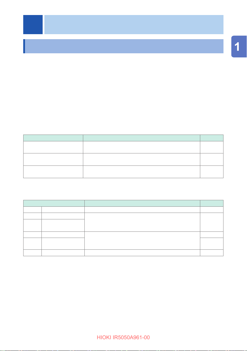
Function Purpose
Insulation resistance
measurement
Voltage measurement To measure the voltage of an external circuit, e.g.,
PV insulation resistance
measurement (IR5051 only)
Insulation diagnosis functions
Function Purpose
TIMER Timer test
PI Polarization index To check whether the insulation resistance increases
DAR Dielectric
absorption ratio
SV Step voltage test To determine whether the insulation resistance of an
Ramp Ramp voltage test p. 66
DD Dielectric discharge To diagnose a multi-layer insulator. p. 68
To test the insulation resistance of an electrical facility. p. 41
commercial power supply.
To measure the insulation resistance of a PV panel. p. 53
To automatically end the test after a predetermined time.
with time after a voltage is applied.
object under measurement is aected by a change in
test voltage.
Reference
p. 50
Reference
p. 59
p. 61
p. 63
17
Page 18
Product Overview
HIOKI IR5050A961-00
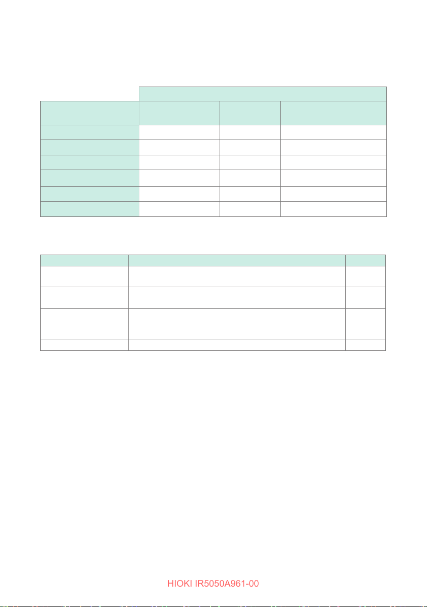
The available insulation diagnosis functions dier depending on the measurement
function.
Available: , not available: –
Measurement functions
Insulation diagnosis
functions
Timer test
Polarization index
Dielectric absorption ratio
Step voltage test
Ramp voltage test
Dielectric discharge
Insulation resistance
measurement
Voltage
measurement
–
– –
– –
– –
– –
– –
PV insulation resistance
measurement (IR5051 only)
Other functions
Function Purpose
Comparator function To compare the measured value against a preset value and
make a pass/fail judgment.
PC communication To create tables or graphs on a PC of the data saved in the
instrument’s memory for reports, etc.
Wireless
communications function
(GENNECT Cross)
Data memory function To save the measurement data. p. 85
To check the measurement data saved in the instrument’s
memory and create measurement reports with a mobile
device.
Reference
p. 71
p. 79
p. 74
18
Page 19
Features
HIOKI IR5050A961-00
1.2 Features
Wide test voltage range
Generates a wide range of test voltages, from 250 V to 5 kV.
The voltage may be chosen from the commonly used presets of 250 V, 500 V, 1 kV,
2.5 kV, and 5 kV; or set to a desired level by increments or decrements of 10 V or 25 V.
See “Rotary switch” (p. 24).
Insulation diagnoses
Equipped with a variety of insulation diagnosis functions.
• Automatic calculation and indication of PI (polarization index), DAR (dielectric
absorption ratio), and DD (dielectric discharge)
• SV (step voltage test) and Ramp (ramp voltage test)
See “Insulation Diagnosis Functions” (p. 59).
Large memory
Stores up to 1000 manual records and 10 logging records. The stored data may be
displayed on the LCD or downloaded to a PC.
See “Recording Measurement Data (Data Memory Function)” (p. 85).
Large, clear display
The large display provides easy viewing. Measurements may also be displayed using
a bar graph, oering the feel of an analog meter.
The LCD is backlit, enabling measurement in poor lighting conditions.
PV insulation resistance measurement function (IR5051 only)
Measures the insulation resistance of a PV panel without the eect of current
generated by power generation.
Comparator function
Compares measured values with the preset values and judges whether the result is
PASS or FAIL. Lights up the backlight in red for a FAIL judgment.
Improved work eciency with wireless communications function
GENNECT Cross (free-of-charge application) allows you to create measurement
reports eciently. The Z3210 Wireless adapter is required.
See “5.3 Wireless Communications Function (GENNECT Cross)” (p. 74).
Improved noise resistance
Uses a shielded cable for L9850-02 and L9850-12 Test Lead for stable measurements.
19
Page 20
Part Names and Functions
HIOKI IR5050A961-00
1.3 Part Names and Functions
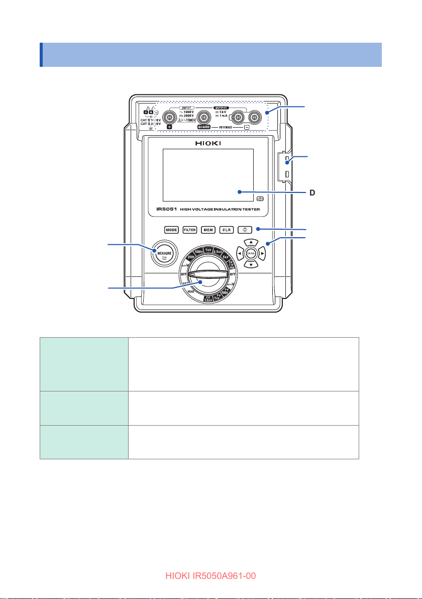
Front (IR5051)
MEASURE key
Rotary switch
(p. 22)
Measurement
terminals
Communications
port
Display (p. 22)
Operation
keys (p. 21)
MEASURE key
(Live line warning
display)
Measurement
terminals
Communications port
20
Starts and stops the insulation resistance measurement.
Blinks in the following cases:
• When a voltage is generated
• When a voltage of 30 V or more is input
• During discharge
+ terminal: Connect the red test lead to this terminal.
− terminal: Connect the black test lead to this terminal.
GUARD terminal: Connect the blue test lead to this terminal.
Connect the DT4900-01 communications package (option) to
download saved data to a PC.
See “5.6 Communicating with PC” (p. 79).
Page 21
Operation keys
HIOKI IR5050A961-00
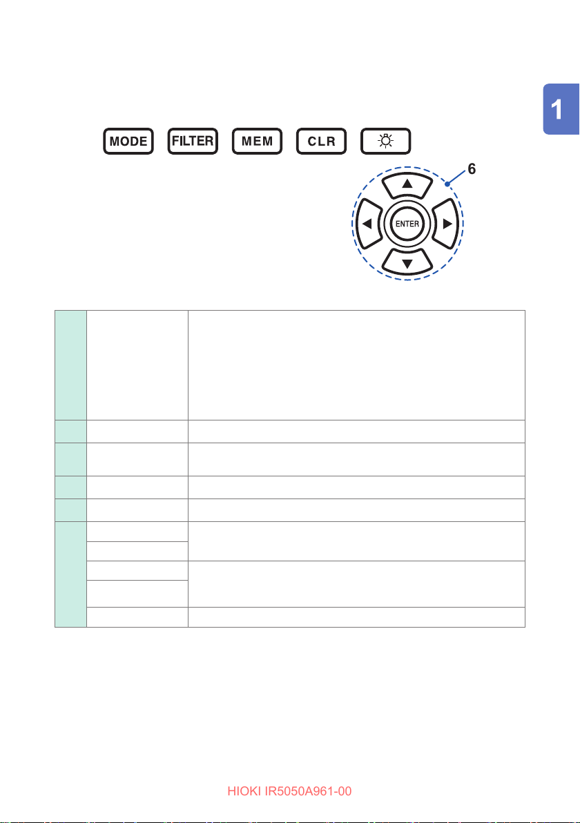
MODE
FILTER Turns the lter function on and o.
MEM
CLR Clears the saved data in the instrument’s memory.
LIGHT key Turns the backlight on and o.
UP () key
DOWN () key
LEFT () key
RIGHT () key
ENTER key Conrms the setting.
Part Names and Functions
Switches the insulation diagnosis function.
The function will change in the following order each time the key is
pressed.
No function displayed*
1
→ [TIMER] → [PI] → [DAR] → [SV] →
[Ramp] → [DD] → No function displayed
*1. Insulation diagnosis function is not available. (The reference
value is displayed when the comparator is set.)
Saves the measured data to the instrument’s memory.
Held down for more than one second to display the date and time.
Changes the set voltage and numerical values.
Moves to locations in a setting and switches the display.
Example: t
display ↔ t2 display
1
Example: Change from year to month in the time setting
21
Page 22
Part Names and Functions
HIOKI IR5050A961-00
Display (IR5051)
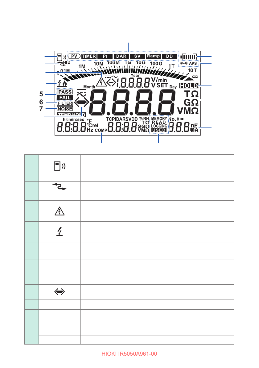
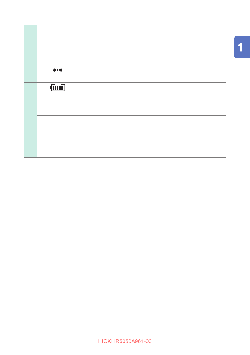
Displays the status of the wireless communications function (Z3210).
Blinking: Connected to a mobile device
Lit: Communications function is on
Not lit: Communications function is o
Indicates the instrument is communicating with the PC (p. 79).
MEMORY
LOGGING
22
HID
PASS
FAIL
FILTER
NOISE
COMP
READ
USED
Indicates the HID function is enabled (p. 76).
Live line warning display
Blinks during the insulation resistance measurement and when there
is voltage between the measurement terminals.
Displayed when insulation breakdown is detected in the object under
measurement during the insulation resistance measurement.
See “Breakdown function” (p. 109).
Indicates the comparator gives a pass judgment.
Indicates the comparator gives a fail judgment.
Indicates the lter function is enabled.
Displayed when noise is detected during the insulation resistance
measurement.
Displayed as [ − ] when the voltage is negative and as [ > ] or [ < ]
when the voltage is overrange.
Displayed when the comparator is set.
Displayed when recording measured data to the instrument.
Displayed when reading measured data recorded to the instrument.
Displayed for logging recording.
Displayed when there is saved data.
Page 23
Part Names and Functions
HIOKI IR5050A961-00
Current value
Static
capacitance value
Unit
HOLD
APS
PV
TIMER
PI
DAR
SV
Ramp
DD
Alternates between the current value and static capacitance value.
(Automatically switches every two seconds.)
Displays the unit that corresponds to the measured value.
Displayed when the measured value is retained.
Indicates the comparator is enabled.
Indicates the automatic power save function enabled.
Indicates the remaining battery level.
Displayed during a PV insulation resistance measurement. (IR5051
only)
Displayed during a TIMER measurement.
Displayed during a PI (polarization index) measurement.
Displayed during a DAR (dielectric absorption ratio) measurement.
Displayed during an SV (step voltage) measurement.
Displayed during a Ramp (ramp voltage) measurement.
Displayed during a DD (dielectric discharge) measurement.
23
Page 24
Part Names and Functions
HIOKI IR5050A961-00
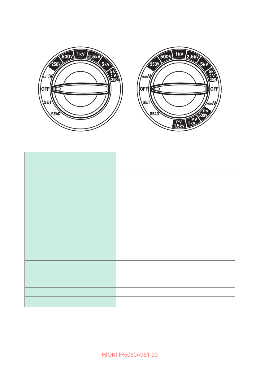
Rotary switch
IR5050 IR5051
Switches the measurement function and sets the test voltage.
Turns o the instrument’s power.
OFF
AUTO V
250V, 500V, 1kV, 2.5kV, and 5kV
5k
▲
V
(User-dened voltage function)
▼
250
PV500V, PV1kV, and PV1.5kV
(IR5051 only)
READ
SET
(IR5051: The same operation is performed for both
left and right OFF.)
Used in voltage measurement.
(IR5051: The same operation is performed for both
left and right AUTO V.)
The test voltage for the insulation resistance
measurement.
The test voltage can be set in greater detail by
pressing the and keys in each range.*
The test voltage for the insulation resistance
measurement.
Use the and keys to set the desired test
voltage.*
1
The setting is retained even when the rotary switch
is set to o.
The test voltage for the PV insulation resistance
measurement.
The test voltage can be set in greater detail by
pressing the and keys in each range.*
Reads saved data.
Sets and changes the functions.
1
1
*1. Setting resolution
250 V to 1 kV: 10-V steps
1 kV to 5.2 kV: 25-V steps
24
Page 25
Back
HIOKI IR5050A961-00
Part Names and Functions
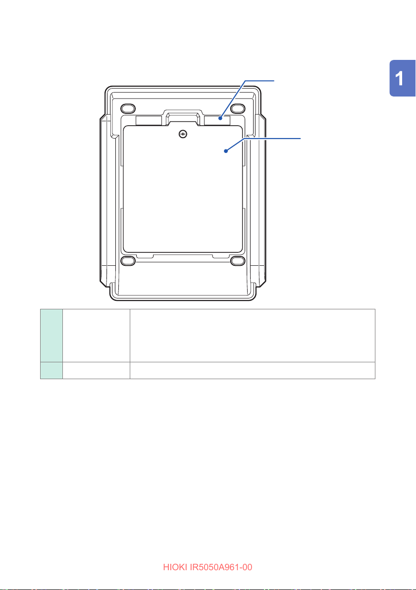
Serial number The serial number consists of nine digits. The rst two digits indicate
Battery cover The cover that stores the batteries and the Z3210.
the year of manufacture, while the second two digits indicate the
month of manufacture. Do not remove this sticker because the
number is important.
The serial number can also be displayed on the LCD. (p. 83)
25
Page 26

Part Names and Functions
HIOKI IR5050A961-00
26
Page 27
2
HIOKI IR5050A961-00
Preparing for Measurement
2.1 Inserting/Replacing Battery
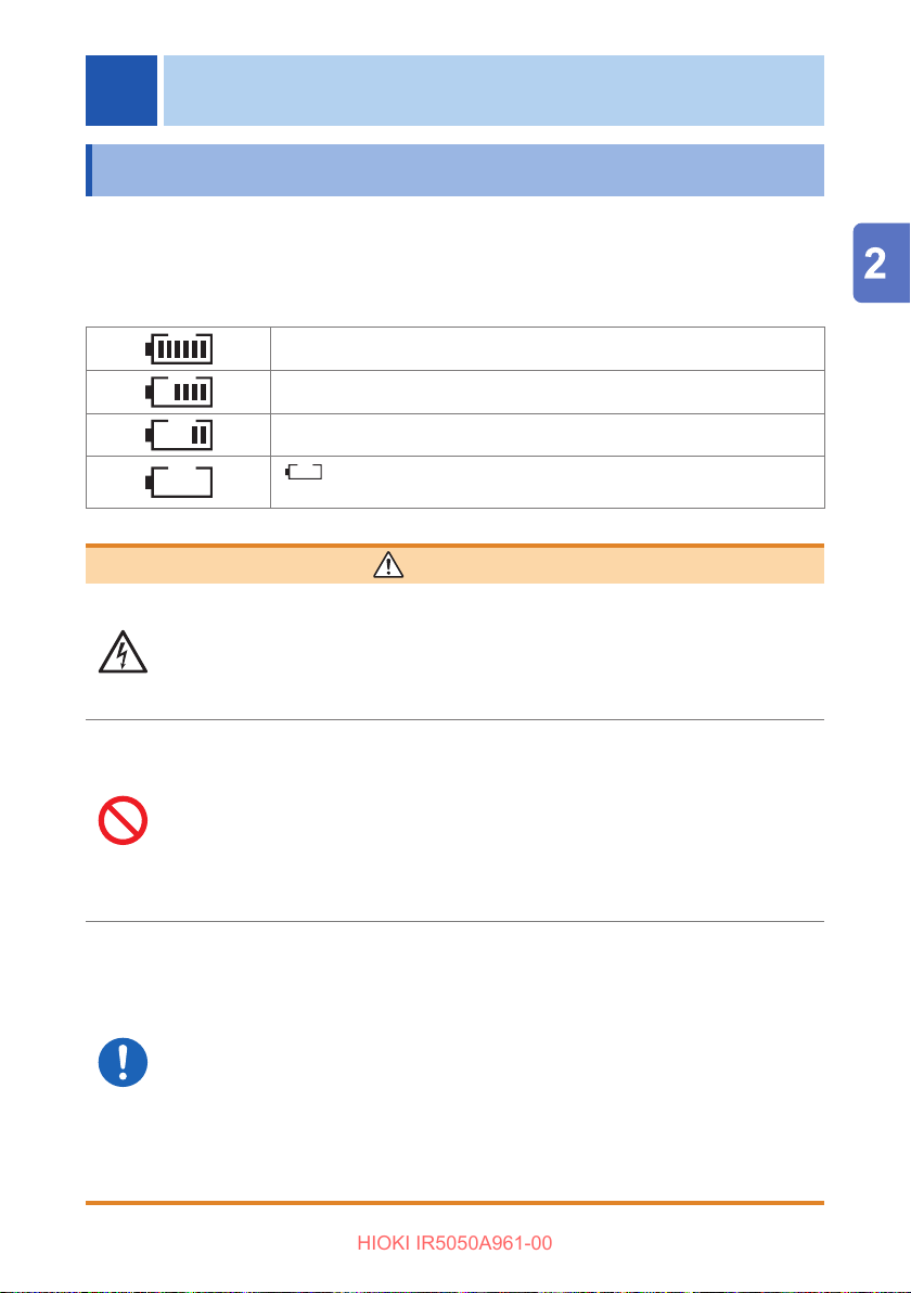
When using the instrument, insert eight LR6 Alkaline batteries or eight fully charged HR6
Nickel-metal hydride batteries. In addition, conrm that the battery status is sucient
before the measurement. When the battery status is low, replace the batteries.
Battery indicator
Sucient charge
When the charge decreases, the bars disappear from the left.
Low charge. Replace as soon as possible.
blinks when the batteries have no charge. In this case,
measurement is not possible. Replace the batteries.
WARNING
When removing the battery cover, turn the rotary switch
to OFF and remove the test leads from the object under
measurement.
Failure to do so could cause the user to experience an electric shock.
Do not short-circuit the batteries.
Do not charge alkaline batteries.
Do not disassemble batteries.
Do not throw batteries in a re or heat them.
Doing so could cause the batteries to rupture, resulting in bodily injury.
After replacing the battery, attach the battery cover and
tighten the screw before using the instrument.
Using the product without the battery cover result in bodily injury.
Secure the battery cover with the screw attached to the
instrument at the time of shipment.
If the battery cover is secured with other screws, the instrument could be
damaged, resulting in bodily injury. If you have lost a screw or nd that the
screw is damaged, contact your authorized Hioki distributor or reseller.
27
Page 28
Inserting/Replacing Battery
HIOKI IR5050A961-00
Do not mix batteries of dierent ages or types.
Do not use batteries that have passed their recommended
expiration date.
Do not reverse the battery polarity.
Do not leave exhausted batteries in the instrument.
Doing so could cause the battery to leak, damaging the instrument.
Use the specied batteries only (LR6 Alkaline battery or fully
charged HR6 Nickel-metal hydride batteries).
Remove the batteries from the instrument when it will not be used
for an extended period.
Failure to do so could cause the battery to leak, damaging the
instrument.
CAUTION
28
Page 29
Nickel-metal hydride batteries
HIOKI IR5050A961-00
Do not expose the batteries to strong impacts and do not
throw them around.
Do not get the batteries wet.
Doing so could damage the batteries and the instrument, resulting in
bodily injury.
Do not use the batteries in excessively humid locations or
locations exposed to rain.
Doing so could damage the batteries and the instrument, resulting in
bodily injury.
If you nd any battery abnormality (for example, leakage,
odor, overheating, discoloration, and deformation) while
using, charging, or storing batteries, stop using them
immediately.
Contact your authorized Hioki distributor or reseller.
Inserting/Replacing Battery
WARNING
IMPORTANT
• The operating temperature range of the batteries included with the instrument
when shipped is from −10
temperature range, use batteries made for low and high temperatures. (Example:
Lithium batteries)
• The capacity of nickel-metal hydride batteries decreases due to self-discharge.
Be sure to charge the batteries before initial use. If the battery capacity remains
very low after correct recharging, replace the batteries with new batteries.
CAUTION
Do not mix LR6 Alkaline batteries and nickel-metal hydride
batteries.
Doing so could cause the battery to leak, damaging the instrument.
C to 45°C. If the instrument will be used outside this
°
29
Page 30
Inserting/Replacing Battery
HIOKI IR5050A961-00
Equipment
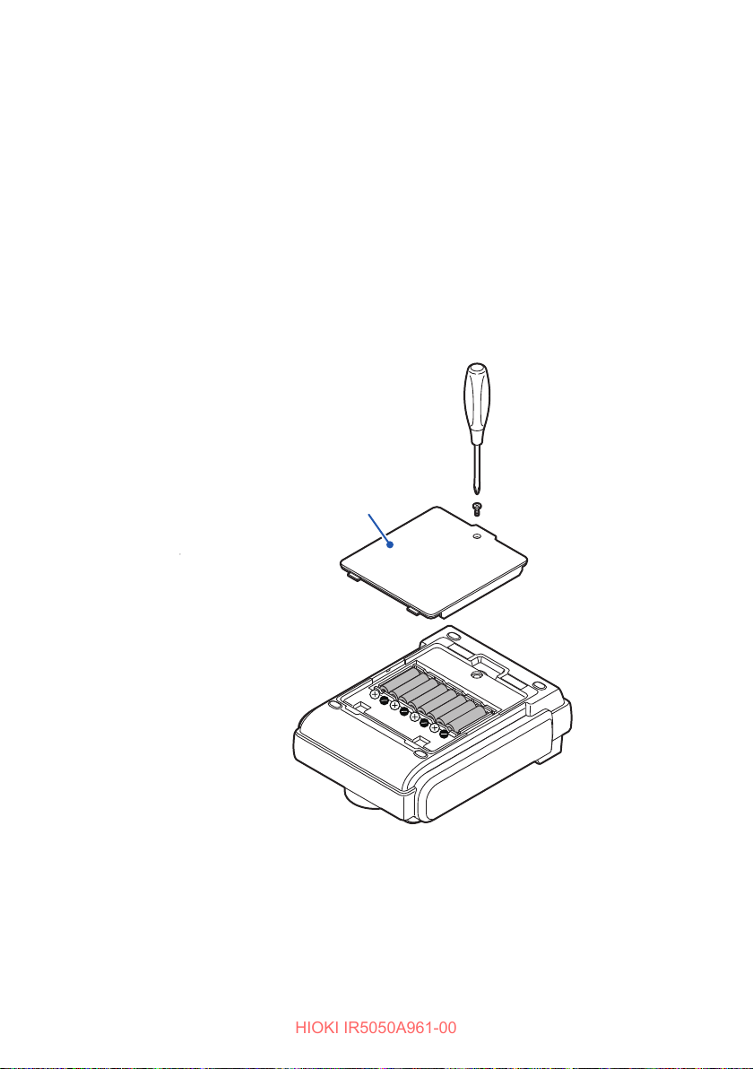
• Phillips screwdriver (No. 2)
• LR6 Alkaline battery
Disconnect the test leads from the instrument.
1
Turn the rotary switch on the instrument to o.
2
Loosen the screw and remove the battery cover.
3
When replacing the batteries, remove all of the old batteries.
4
Replace all eight batteries.
Insert the new batteries while being careful about the correct polarity.
5
Reattach the battery cover and tighten the screw.
6
8 or HR6 Nickel-metal hydride battery × 8
×
Battery cover
30
Back
Page 31
Installing the Z3210 Wireless Adapter
HIOKI IR5050A961-00
2.2 Installing the Z3210 Wireless Adapter
Install the Z3210 wireless adapter (option) in the instrument to allow the use of the
wireless communications function.
See “5.3 Wireless Communications Function (GENNECT Cross)” (p. 74).
WARNING
When removing the battery cover, turn the rotary switch
to OFF and remove the test leads from the object under
measurement.
Failure to do so could cause the user to experience an electric shock.
After installing the Z3210, attach the battery cover and
tighten the screw before using the product.
Using the product without the battery cover result in bodily injury.
Secure the battery cover with the screw attached to the
instrument at the time of shipment.
If the battery cover is secured with other screws, the instrument could
be damaged, resulting in bodily injury. If you have lost a screw or nd
that the screw is damaged, contact your authorized Hioki distributor or
reseller.
CAUTION
Before handling the Z3210, eliminate static electricity on your body
by touching any metallic part, such as a doorknob.
Failure to do so could cause static electricity to damage the Z3210.
31
Page 32
Installing the Z3210 Wireless Adapter
HIOKI IR5050A961-00
Equipment
• Phillips screwdriver (No. 2)
• Flathead screwdriver
• Z3210 wireless adapter (option)
Disconnect the test leads from the instrument.
1
Turn the rotary switch on the instrument to o.
2
Loosen the screw and remove the battery cover.
3
Remove batteries.
4
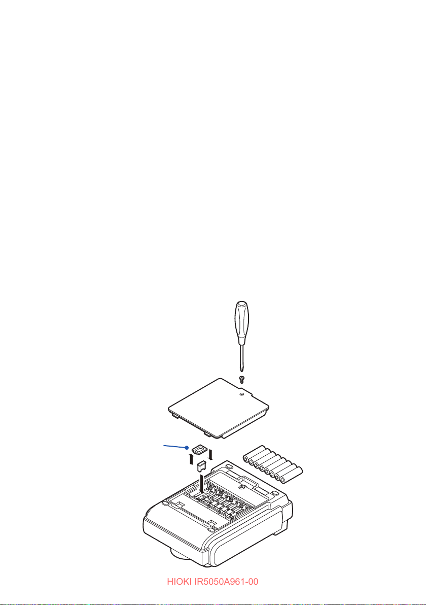
Remove the protective cap from the instrument.
5
Insert the Z3210 completely while being careful about the correct
6
orientation.
Reattach the protective cap.
7
Insert batteries.
8
Reattach the battery cover and tighten the screw.
9
When removing the Z3210, use a tool such as a athead screwdriver to remove it.
32
Protective cap
Page 33
Setting and Checking Date and Time
HIOKI IR5050A961-00
2.3 Setting and Checking Date and Time
Set or check the time and date before use of the instrument.
Use the Gregorian calendar.
Setting date and time
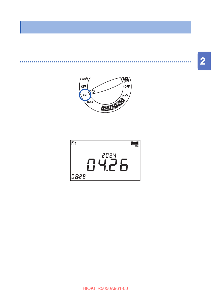
Turn the rotary switch to SET.
1
Hold down the MEM key for more than one second.
2
The year, month, day, hours, minutes, and seconds appear.
The selected location starts blinking.
Year
Month Day
Press the key or key and move to the location to set.
3
Press the ▲ key or the ▼ key to set the numerical value.
4
Hold down a key for fast increase/decrease of the numerical value.
Press the ENTER key to conrm the numerical value.
5
The LCD returns to the previous display.
The clock starts to run as soon as the ENTER key is pressed.
The time can also be set from a PC.
• The date and time can be set up on a PC using Sequence Maker.
• Sequence Maker must be installed on the PC.
See “5.6 Communicating with PC” (p. 79).
hr:min:sec
33
Page 34

Setting and Checking Date and Time
HIOKI IR5050A961-00
Checking date and time
Turn the rotary switch to any position other than OFF.
1
Hold down the MEM key for more than one second.
2
Displays the currently set year, month, day, hours, minutes and seconds.
Press any key to return to the original display.
34
Page 35
2.4 Connecting Test Leads
HIOKI IR5050A961-00
DANGER
Check that the insulation on the leads is not damaged and
that the conductors in the leads are not exposed before use.
Using test leads or an instrument that are damaged could lead to serious
bodily injury. If you nd any damage, replace with a Hioki-specied part.
WARNING
Do not use the instrument with the test leads connected for
measurements that exceed any of the ratings marked on
them.
Using the product for measurements that exceed any ratings could
cause the user to experience an electric shock.
Use only Hioki-specied test leads with the instrument.
Using an unspecied test lead could result in bodily injury or a short-
circuit fault.
Connecting Test Leads
IMPORTANT
Be sure to clean test leads after use. If test leads are dirty, they may deteriorate.
CAUTION
Do not bend or pull on cables at temperatures of 0°C or lower.
Cables could harden in low temperatures. Bending or pulling a cable
under these conditions could cause a break in the cable or damage the
insulation, resulting in an electric shock.
Do not allow test leads to contact each other or place objects on
test leads.
Doing so could cause measurement errors and malfunctions.
35
Page 36
Connecting Test Leads
HIOKI IR5050A961-00
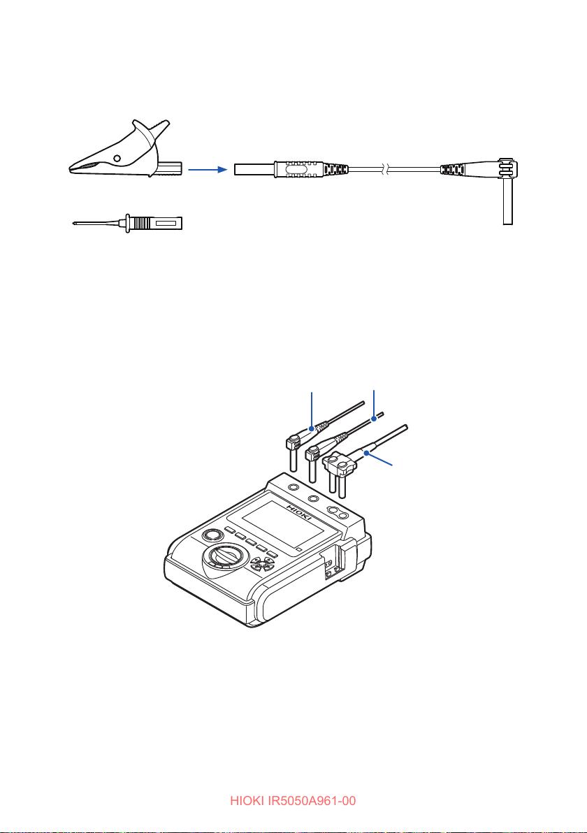
Connect alligator clips or test pins (IR5051 only) to the ends of test leads.
1
Insert it fully.
or
Connect the red test lead to the + terminal and the black test lead to the
2
− terminal.
For insulation resistance measurement, connect the blue test lead to the
1
GUARD terminal*
Insert it fully.
if necessary.
Red
Blue
*1. A GUARD terminal is used to prevent the surface electrical resistance of an
insulating material aecting measurement, enabling correct measurement of the
entire volume resistivity of the material.
See “3.6 Use of GUARD Terminal” (p. 48).
36
Black
Page 37
3
HIOKI IR5050A961-00
Making Measurements
3.1 Measurement Procedure
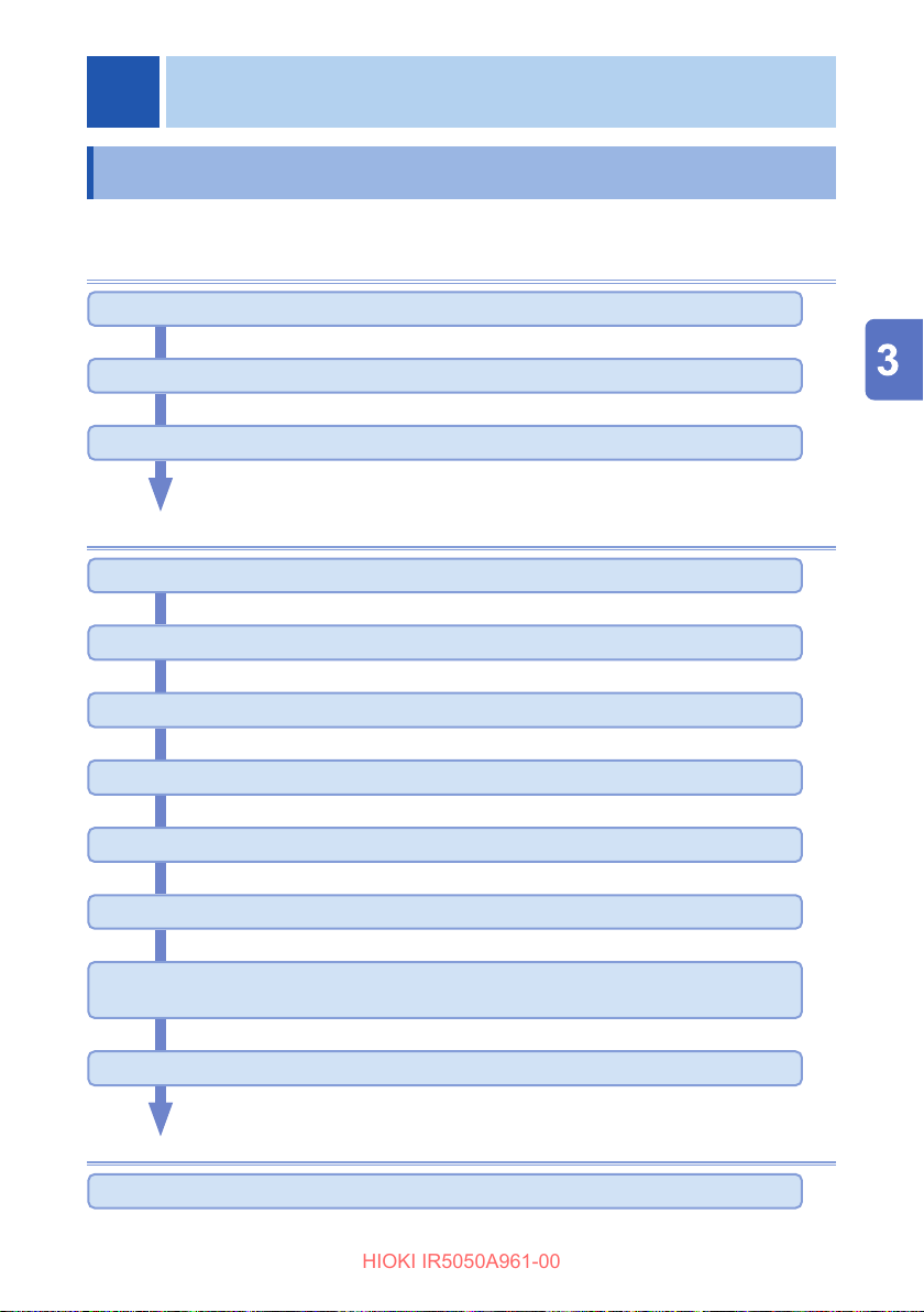
Always read the information in “Precautions for Use” (p. 15) before using the instrument.
Preparations
Insert the batteries. (p. 27)
Prepare other options as necessary.
Set the date and time. (p. 33)
Perform the pre-operation inspection. (p. 38)
Measurement (insulation resistance)
Make sure that power supply to the object under measurement is turned o.
Set the test voltage with the rotary switch.
Connect the test leads to the instrument.
Connect the test leads to the object under measurement.
Generate voltage and start measurement.
Check the displayed value.
With the test leads connected to the object under measurement, press the
MEASURE key to end voltage generation and measurement.
Discharge remaining electric charge with automatic discharge function.
Stop
Turn the rotary switch to OFF and remove the test leads from the object under measurement.
37
Page 38
Pre-Operation Inspection
HIOKI IR5050A961-00
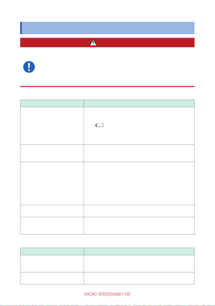
3.2 Pre-Operation Inspection
DANGER
Inspect the instrument and verify proper operation before
use.
Use of the instrument while it is malfunctioning will result in serious
bodily injury.
If you nd any damage, contact your authorized Hioki distributor or reseller.
Inspecting the instrument
Inspection item Action
The battery level is sucient. Turn the rotary switch to any position other than OFF. With
the power on, check the battery indicator at the top-right
corner of the LCD.
symbol is blinking, the battery level is low.
▲
250 V and
.
2505k
V
▼
The display has no missing
segment.
The live line warning display
(MEASURE key) works properly.
The instrument does not have
any damage or cracks.
The measurement terminals do
not have any foreign matter, such
as sand, in them.
If the
Replace the batteries with fresh ones. When using nickel-
metal hydride batteries, charge the batteries.
See “2.1 Inserting/Replacing Battery” (p. 27).
Check with the fully lit display.
If any parts are missing, request repair.
See “5.7 Power On Options List” (p. 82).
Check with the following procedure.
1. Turn the rotary switch to one of the selections between
2. Press the MEASURE key for at least one second.
3. Check if the MEASURE key is blinking.
4. Press MEASURE key to end the check.
If the key is not blinking, do not use the instrument and
request for repair.
Check visually.
If the instrument is damaged, do not use it. Request repair.
Remove any foreign objects if any.
If the foreign objects cannot be removed, request repair.
Inspecting the accessories and options
Inspection item Action
The test leads or cables have no
damaged insulation or no exposed
inner white parts or metal.
The clips or test pins does not
have any damage or cracks.
38
If you nd any damage, there is a risk of electric shock.
Replace the parts with Hioki-specied parts.
Check visually.
Do not use if damaged. Replace the parts with new parts.
Page 39
Pre-Operation Inspection
HIOKI IR5050A961-00
Checking the insulation resistance measurement
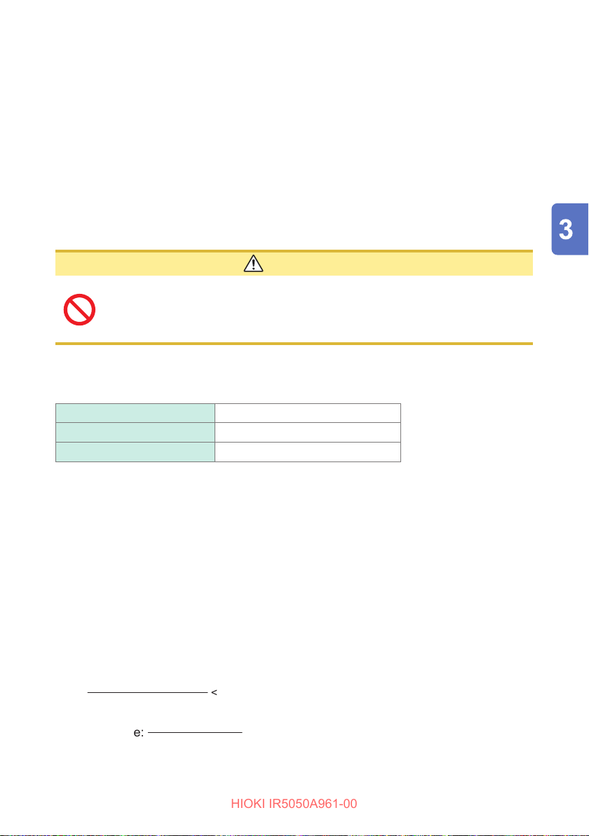
Inspect the following before starting a test to use the instrument safely.
Inspect whether the measured resistance matches the prepared resistance.
If a problem exists, do not use the instrument and request repair.
Equipment:
Recommended resistance: GS Series High Voltage, High Resistance Thick Film
Resistor or equivalent product (pay attention to the
operating voltage and power)
Manufacturer: KOA Corporation
CAUTION
Do not allow the test voltage (power) to exceed the rated voltage
(power) of the prepared resistor.
Doing so could damage the resistor.
Setting example: When the insulation resistance of the object under measurement is
100 M
Ω
Maximum operating voltage 1000 V
Rated power
Test voltage 500 V
0.5 W
Prepare the resistor.
1
Conrm that the test voltage is less than the maximum operating voltage
2
of the prepared resistor.
Test voltage < Maximum operating voltage of prepared resistor
(Example: 500 V < 1000 V)
Conrm that the value calculated from the test voltage and resistance is
3
less than the rated power of the prepared resistor (if the value calculated
from the test voltage and resistance is greater than the rated power of the
prepared resistor, change the resistor or change the test voltage).
Square of test voltage
(Example:
Set the test voltage to 500 V.
4
Resistance
500 V × 500 V
< Rated power of prepared resistor
100 M
Ω
= 0.0025 W < 0.5 W
)
39
Page 40

Pre-Operation Inspection
HIOKI IR5050A961-00
Clip the resistor with the red and black test leads connected to the
5
instrument.
Hold down the MEASURE key for more than one second to start insulation
6
resistance measurement.
See “3.3 Measuring Insulation Resistance” (p. 41).
Check to see if the voltage monitor value reading of the instrument is
7
between 500 V and 550 V.
Check to see if the insulation resistance reading of the instrument is
8
Ω
100 M
Press the MEASURE key to end the insulation resistance measurement.
9
Short-circuit the tips of the clips of the red and black test leads of the
10
instrument.
Set the test voltage to 500 V.
11
Hold down the MEASURE key for more than one second to start insulation
12
resistance measurement.
Check to see if the insulation resistance reading of the instrument is
13
0.00 M
Press the MEASURE key to end the insulation resistance measurement.
14
.
Ω
.
40
Page 41
Measuring Insulation Resistance
HIOKI IR5050A961-00
3.3 Measuring Insulation Resistance
DANGER
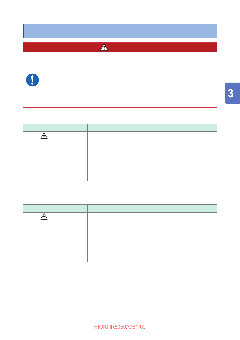
To avoid an electric shock and a short-circuit, make sure to
observe the following precautions.
1. Check Table 1 before connecting test leads to the instrument.
2. Check to see if the object under measurement is not live or electrically
charged using a high-voltage detector or other similar instrument,
before connecting test leads to it.
Table 1
Check item Result Action
Are the
MEASURE key lamp o?
mark and
O Connect test leads to the
Blinking Press the MEASURE key to
instrument and check 2
above.
If safe to proceed, connect the
test leads to the object under
measurement. Go to Table 2.
stop voltage generation.
Table 2
Check item Result Action
Are the
MEASURE key lamp blinking?
mark and
Not blinking A measurement can be
performed.
Blinking Immediately disconnect the
test leads from the object
under measurement and turn
o power to the object or
discharge the electric charge
using a discharge rod.
41
Page 42
Measuring Insulation Resistance
HIOKI IR5050A961-00
Do not measure insulation resistance while an object under
measurement is energized.
Doing so could damage the instrument, resulting in bodily injury.
Shut o the power to the object under measurement before measurements.
Do not touch the connecting part of terminals and alligator
clips during measurement.
Doing so could damage the test leads, causing the user to experience
an electric shock.
Do not touch the object under measurement or disconnect
the test leads after measurement has been completed until
the automatic discharge function is completed.
Electric shock may result due to high voltage and stored charge.
Check the position of the rotary switch before measurement.
Remove the test leads from the object under measurement
before changing the position of the rotary switch.
Failure to do so could cause serious bodily injury, a short-circuit fault or
damage to the instrument.
If the instrument’s power is lost during measurement, such
as due to battery consumption, when the rotary switch is
in a position other than OFF, discharge the object under
measurement using a discharge rod.
The automatic discharge function will not operate fully and electric shock
may result.
WARNING
42
CAUTION
Do not measure the insulation resistance between the
terminals of capacitors (with a capacitance of over 25 µF).
Doing so could damage the instrument during discharge.
Do not short-circuit the tips of the clips of the red test lead
(+ terminal) and the blue test lead (GUARD terminal).
Doing so could damage the instrument.
Be sure to check the test voltage before starting measurement.
Otherwise there is a risk of damage to the object under measurement.
Page 43
Measuring Insulation Resistance
HIOKI IR5050A961-00
IMPORTANT
• Insulation resistance is unstable. The indication may not stabilize depending on
the object under measurement.
• Depending on the charging current owing to the capacitance component of the
object under measurement and the associated absorption current, a value smaller
than the actual resistance value may be displayed after measurement starts. The
display value may then gradually increase and approach the actual resistance value.
• During measurement, if the resistance of the object under measurement suddenly
drops or if the test lead tips are short-circuited, the instrument stops voltage
generation as a safety measure. (This applies to a test voltage of 1100 V or more.)
See “Breakdown function” (p. 109).
• If the rotary switch is turned o during measurement, automatic discharge is
performed before power is turned o.
• If the battery runs low during measurement, the instrument automatically stops
measurement. After automatic discharge is performed, the display changes as
follows and the power is turned o.
[Lo bAtt] → [P.oFF]
• When measuring a capacitive load, the current may ow in reverse if the voltage
charged in the object under measurement is larger than the set output voltage
and for other reasons such as output voltage uctuations. If the measured
current value is negative, the current indication blinks.
• Turn the rotary switch to OFF after use.
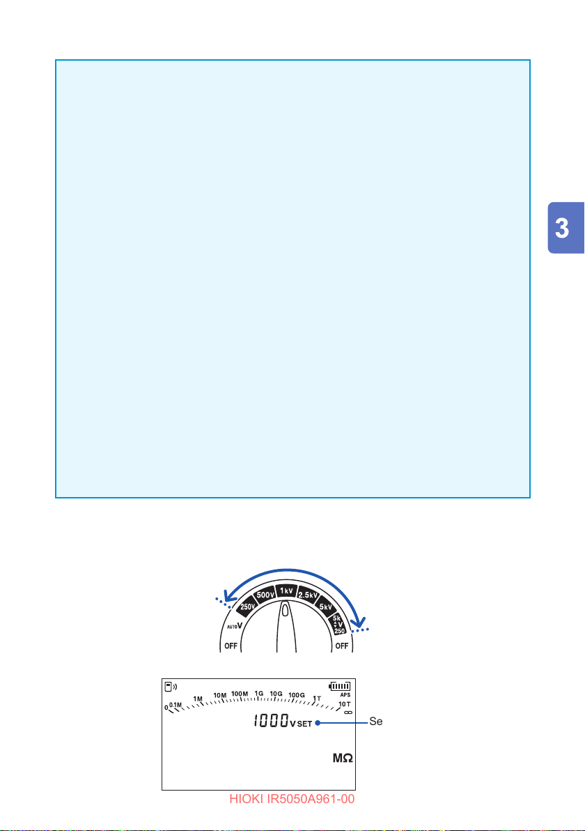
Turn the rotary switch to one of the selections between test voltage 250 V
1
and
You can also press the and keys to set the desired test voltage.
▲
2505k
V
.
▼
TIMER
PI DAR S V
Ramp
DD
Set voltage
43
Page 44
Measuring Insulation Resistance
HIOKI IR5050A961-00
Connect the test leads to the instrument. (p. 35)
2
Connect the test leads to the object under measurement.
3
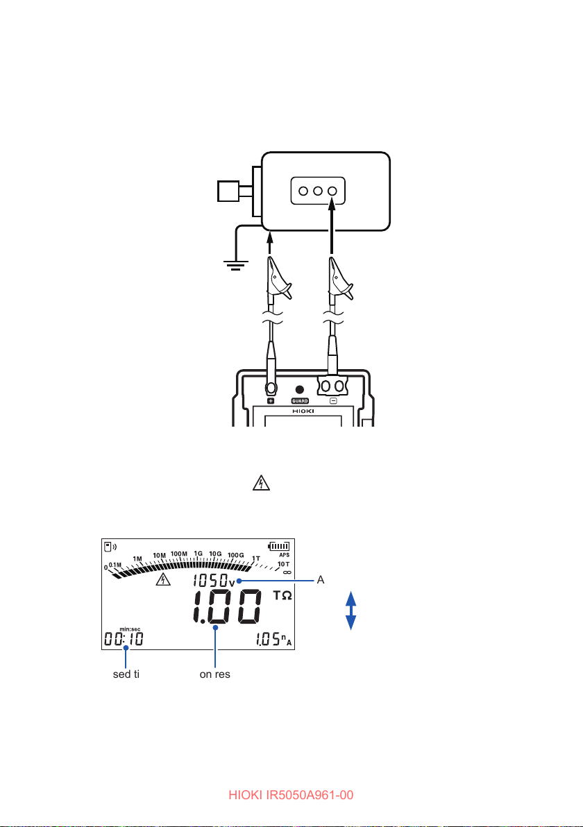
Clip the alligator clip at the end of each test lead to the object under
measurement.
Example of the object to be
measured: Motor
Test lead (Red)
Attach to a metal
chassis or a
ground terminal.
Hold down the MEASURE key for more than one second to start
4
measurement.
Voltage is generated, and the mark and MEASURE key start blinking.
The display changes from the set voltage to the actual output voltage. A voltage
approximately 5% higher than the set level is output.
PI D D
Actual output voltage
Set voltage
Insulation resistanceElapsed time
Test lead (Black)
Attach to a metal
part of the power
supply terminal.
Press the ▲ key to
display the set voltage
for two seconds.
During measurement, if the output voltage is lower than the set voltage, the
•
voltage indication blinks.
• During measurement, if the measured current is negative, the current indication
blinks.
44
Page 45
Measuring Insulation Resistance
HIOKI IR5050A961-00
When the display has stabilized, check the value.
5
If the indication is unstable, enable the lter function. An average of the
measured value is displayed.
See “3.5 Filter Function” (p. 47).
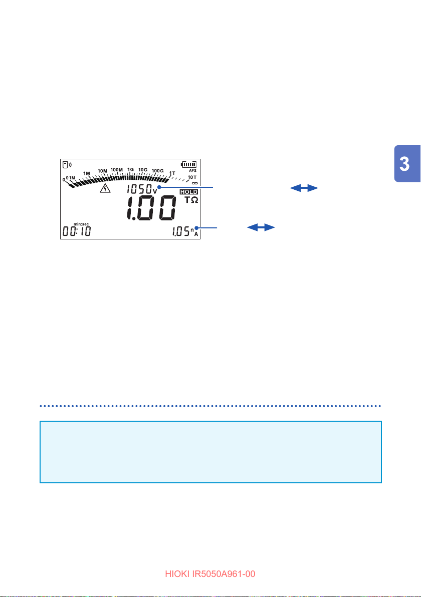
With the test leads connected to the object under measurement, press the
6
MEASURE key to end measurement.
The last measurement is retained ([HOLD] is lit) and voltage generation and
measurement are stopped.
PI D D
Automatically switches every two seconds.
Actual output voltage
Current
When measuring for 1 min. or more, the 1-min. value can be displayed with the
or key, either during or after measurement.
Discharge the electric charge that remains in the object under
7
measurement.
After measurement has been completed, the discharge circuit in the instrument
automatically discharges the electric charge remaining in the object under
measurement.
See “3.4 Automatic Discharge Function” (p. 46).
Static capacitance
Set voltage
Retention of the measured value
IMPORTANT
The retained measured values are cleared when power is turned o. To save the
data, use the memory function.
See “Recording Measurement Data (Data Memory Function)” (p. 85).
Deleting the retained data
To clear the data, press the CLR key.
45
Page 46
Automatic Discharge Function
HIOKI IR5050A961-00
3.4 Automatic Discharge Function
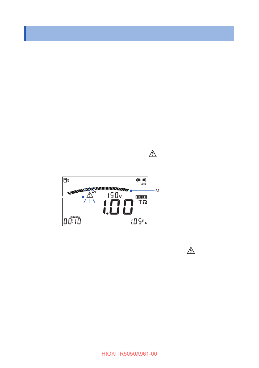
After the measurement, discharge the electric charge in the object under
measurement.
When insulation resistance with a capacitance component is measured, this
component remains charged with a high-voltage equivalent to the test voltage, which
is dangerous.
This instrument can automatically discharge remaining electric charge using the
internal circuit after measurement.
With the test leads connected to the object under measurement, press the
MEASURE key to end measurement.
The charge remaining in the object under measurement is automatically discharged
with the discharge resistance inside the instrument.
During discharge, the voltage is displayed and the
continue blinking.
The bar graph decreases according to the voltage.
mark and MEASURE key
Blinks
Discharging stops when the residual voltage falls below 30 V. The mark goes out.
The discharge time varies depending on the capacitance.
46
Moves according to voltage
During discharge
Page 47
Filter Function
HIOKI IR5050A961-00
3.5 Filter Function
If the indication is unstable, the average of the measurement is shown.
Setting method
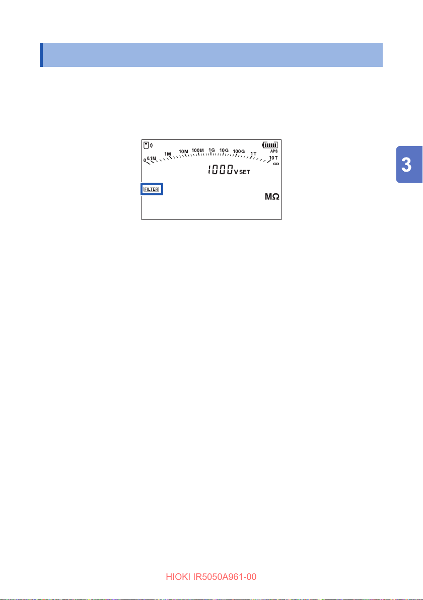
Hold down the FILTER key to enable or disable the function.
When the lter function is enabled, [FILTER] appears on the LCD.
Year
Ramp
MEMORY
READ
LOGGING
USED
DD
No.
TIMER
HID
FILTER
NOISE
hr:min:sec
PI DAR S V
Month Day
TCPIDARSVDD
COMP
While [FILTER] is enabled, display update interval is four seconds. But in the
following cases, the interval is one second.
• During 15 seconds after the measurement started
• During 5 to 10 seconds after the measurement range changed
47
Page 48
Use of GUARD Terminal
HIOKI IR5050A961-00
3.6 Use of GUARD Terminal
Measurement unaected by surface electrical resistance
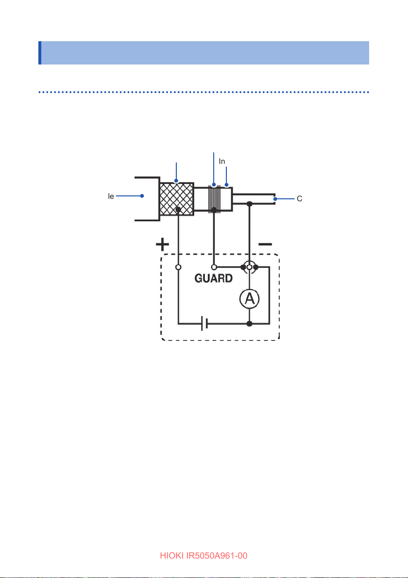
A GUARD terminal is used to prevent the surface electrical resistance of an insulating
material aecting measurement, enabling correct measurement of the entire volume
resistivity of the material.
Bare conductor
Metallic shielding layer
Insulating material
Cable
Current detector
Power supply
When testing the insulation of a cable, as shown in the diagram above, wind a bare
conductor around the surface of the insulating material and connect the conductor
to the GUARD terminal. This prevents the leakage current on the surface of the
insulating material owing into the current detector, which enables the actual
resistance of the entire volume of the insulating material to be measured.
Core
48
Page 49
Use of GUARD Terminal
HIOKI IR5050A961-00
Measurement using G (GUARD) terminal grounding
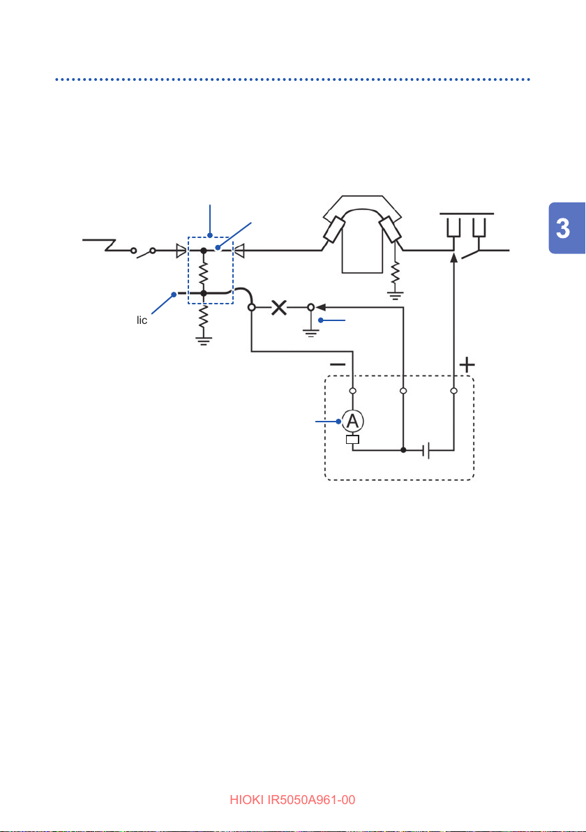
G terminal grounding is used for measuring the insulation resistance between
the core and the metallic shielding layer of a high-voltage cable with the cable
connected to other high-voltage equipment. The diagram below shows an example of
measurement.
Meter transformer
Power supply side
Cable
Core wire
Disconnector
Load side
Rn
GUARD
Ro
Power supply
Metallic
shielding layer
of the cable
Rc
Remove
P
Rs
Current detector
N
Grounding
wire
Rc: Insulation resistance of the insulating material of the high-voltage cable (Between
core and metallic shielding layer)
Rs: Insulation resistance of the sheath of the high-voltage cable (Between metallic
shielding layer and ground)
Rn: Insulation resistance between insulator or high-voltage equipment and ground
Ro: Instrument’s internal resistance (approx. 3 k
)
Ω
Inuence of Rs and Rn is removed and solely Rc is measured.
For details, refer to regulations for high-voltage power receiving facility.
49
Page 50
Measuring Voltage
HIOKI IR5050A961-00
3.7 Measuring Voltage
The instrument measures the voltage of an external circuit, e.g., commercial power
supply. It automatically determines AC voltage or DC voltage.
DANGER
Do not allow the tip of test leads to short-circuit two wires
across which a voltage is applied.
Doing so will cause a short-circuit fault, resulting in serious bodily injury.
WARNING
When measuring power line voltage, use test leads that
satisfy the following conditions:
• IEC 61010 or EN 61010 safety standard-compliant
• Rated for measurement category III or IV
• Rated voltage higher than voltage being measured
Failure to do so could cause the user to experience an electric shock.
The test leads included with the instrument comply with the EN 61010
safety standard. Observe the measurement category and rated voltage
indicated on the test leads during use.
50
CAUTION
Do not input voltage from an external source when the rotary
switch is set to OFF.
Do not input voltage from an external source to GUARD terminal.
Doing so could damage the instrument.
Page 51
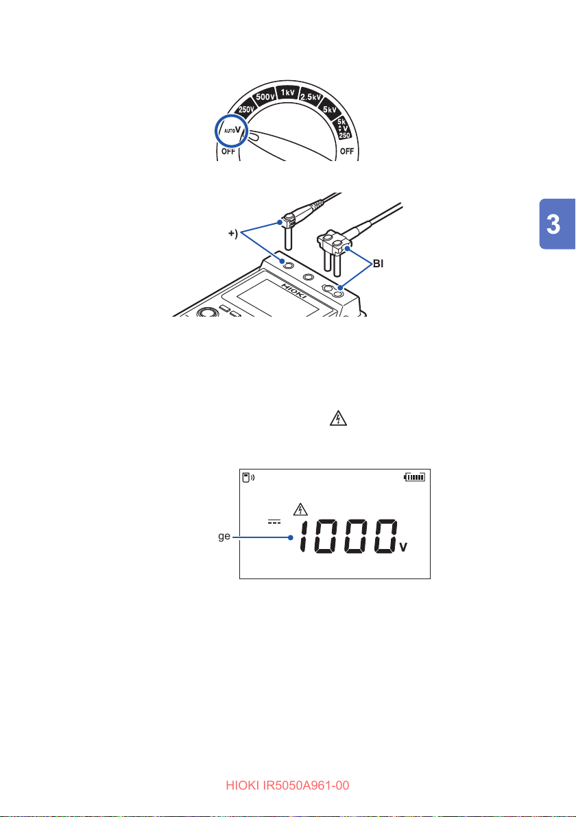
Turn the rotary switch to AUTO V.
HIOKI IR5050A961-00
1
Connect the test leads to the instrument. (p. 35)
2
Red (+)
Black (−)
Connect the test leads to the object under measurement.
3
Clip the alligator clip at the end of each test lead to the object under
measurement.
Check the value.
4
When a voltage of 30 V or more is input, the
mark and MEASURE key start
blinking.
Example: Direct current (DC)
Year
Ramp
MEMORY
READ
LOGGING
USED
DD
No.
Measured voltage
TIMER
HID
FILTER
NOISE
hr:min:sec
PI DAR S V
Month Day
TCPIDARSVDD
COMP
Measuring Voltage
You can retain the measured value by pressing the MEASURE key. ([HOLD]
lights up.)
To cancel the held value, press the MEASURE key again.
51
Page 52
Negative Voltage Notication Function (IR5051 Only)
HIOKI IR5050A961-00
3.8 Negative Voltage Notication Function
(IR5051 Only)
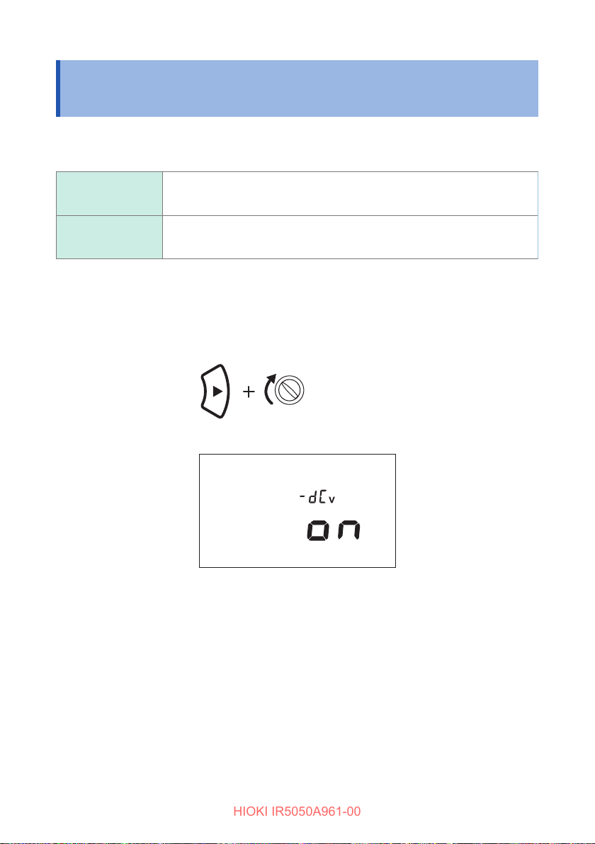
This function checks if the P and N connections are reversed when measuring the
open voltage of a PV string.
ON
(default)
When the voltage is −10 V or less, the backlight lights up alternating
between white and red.
OFF Disabled
Checking and changing the setting
Turn o the power by turning the rotary switch to OFF.
1
While holding down the (RIGHT) key, turn the rotary switch to any
2
position to turn on the power.
(Any position)
The current setting appears.
Year
Ramp
MEMORY
READ
LOGGING
USED
DD
No.
TIMER
HID
FILTER
NOISE
hr:min:sec
PI DAR S V
Month Day
TCPIDARSVDD
COMP
To change the setting, repeat steps 1 and 2.
3
The setting is saved even when the power is turned o.
52
Page 53
PV Insulation Resistance Measurement Function (IR5051 Only)
HIOKI IR5050A961-00
3.9 PV Insulation Resistance Measurement Function (IR5051 Only)
This function can accurately measure the insulation resistance between a PV panel
and ground without being aected by power generation. For a measurement between
the connection box output terminal and ground and between the power conditioner
and ground, use the insulation resistance measurement function, not the PV
insulation resistance measurement function (p. 41).
WARNING
Do not measure insulation resistance while an object under
measurement is energized.
Doing so could damage the instrument, resulting in bodily injury.
Shut o the power to the object under measurement before
measurements.
Do not touch the object under measurement or disconnect
the test leads after measurement has been completed until
the automatic discharge function is completed.
Electric shock may result due to high voltage and stored charge.
Do not directly touch the metal parts of the connection box,
disconnector, and other devices.
Electric shock may result due to high voltage from power generation.
Securely connect the measurement cables to the
measurement terminals.
Loose terminals could increase contact resistance and cause the
instrument to overheat, resulting in instrument burnout or re.
When measuring a PV panel, make sure to turn o the
disconnector or other device to separate the panel from the
power conditioner.
Make the measurement using sucient caution to protect
against electric shock because PV cells always generate
power and hazardous voltage during the day.
Failure to do so could cause the user to experience an electric shock.
53
Page 54
PV Insulation Resistance Measurement Function (IR5051 Only)
HIOKI IR5050A961-00
CAUTION
Do not measure insulation resistance if the PV panel is faulty.
The bypass diode connected to the PV panel may be damaged.
IMPORTANT
• Insulation resistance is the ratio of applied voltage to leakage current. The
indication may not stabilize depending on the object under measurement, but
this is not an instrument malfunction.
• During measurement, if the resistance of the object under measurement
suddenly drops or if the test lead tips are short-circuited, the instrument stops
voltage generation as a safety measure. (This applies to a test voltage of 1100 V
or more.)
See “Breakdown function” (p. 109).
• Turn the rotary switch to OFF after use.
• When testing a circuit connected to a device with low withstand voltage or
a device/part with unknown withstand voltage using test voltage, taking the
measurement by disconnecting the device/part is recommended.
• It may take time for the measured value to stabilize because a PV panel has a
large ground capacitance.
• If the open voltage of a PV string is larger than the test voltage, correct
measurement may not be possible.
• If a voltage is being generated greater than the test voltage, the buzzer beeps
and measurement is not possible.
• For a measurement using the method that short-circuits between P-N, use an
insulation resistance range other than one for PV insulation resistance.
• Use the method that short-circuits between P-N when the PV panel is not
generating power, such as at night.
• PV insulation resistance measurement function is connected to approx. 660 k
of current-limiting resistance on the + (positive) terminal, so the output voltage
is divided by approx. 660 k
measurement terminals.
Example: When a resistance of 10 M
divided by approx. 660 k
and the resistance connected between the
Ω
was measured, the output voltage was
Ω
and 10 MΩ.
Ω
Ω
54
Page 55
PV Insulation Resistance Measurement Function (IR5051 Only)
HIOKI IR5050A961-00
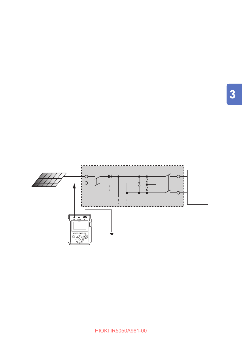
This section describes the insulation resistance measurement between a PV panel
and ground using the method not to short-circuit between P-N.
See “9.7 Measurement Methods for Insulation Resistance of PV Array” (p. 125).
This instrument measures PV module insulation resistance in accordance with the
IEC/EN 62446-1 guidelines.
Measurement preparations
In the connection box, turn o the main switch and disconnect the
1
connection to the power conditioner.
Turn o the disconnectors for all PV strings.
2
Disconnect any lightning arresters on the measurement circuit.
3
For the case in the following diagram (solar power generation facility), the
lightning arrester does not need to be disconnected because it is not on the PV
string side of the disconnector.
Example: Solar power generation facility
String
P (+)
O
Disconnector Main switch
O
12
N (−)
Lightning
arrester
Connection
box
Power
conditioner
55
Page 56
PV Insulation Resistance Measurement Function (IR5051 Only)
HIOKI IR5050A961-00
Measurement
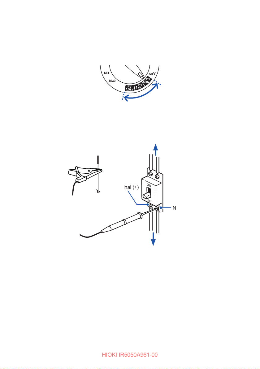
Turn the rotary switch to test voltage PV500V, PV1kV, or PV1.5kV.
1
You can also press the and keys to set the desired test voltage.
Connect the test leads to the instrument. (p. 35)
2
Connect the black test lead to the ground terminal.
3
Connect the red test lead to the N terminal on the PV string side.
4
Power conditioner, main switch
3
(Black)
P terminal (+)
Disconnector
There is a risk of insulation deterioration when voltage is generated between the
N terminal and ground. When there is voltage in the object under measurement,
the backlight blinks in red by the voltage detection function.
56
Ground terminal
N terminal (−)
4
(Red)
String
Page 57
PV Insulation Resistance Measurement Function (IR5051 Only)
HIOKI IR5050A961-00
Hold down the MEASURE key for more than one second to start
5
measurement.
Voltage is generated, and the mark and MEASURE key start blinking.
Do not disconnect the test leads from the terminals during the measurement.
Correct measurement is not possible.
IMPORTANT
For the PV insulation resistance measurement, press the MEASURE key after the
test leads are connected to the object under measurement. Correct measurement
is not possible if the test leads are connected to the object under measurement
when the MEASURE key has been pressed and voltage is being generated.
When the resistance appears, check the value.
6
If the indication is unstable, enable the lter function. An average of the
measured value is displayed.
See “3.5 Filter Function” (p. 47).
IMPORTANT
If there is insulation deterioration and the resistance is lower than the reference
value, do not measure the P terminal side in step 8. The PV panel may be
damaged. For the insulation resistance reference value, check in the safety
regulations and other information in advance.
Press the MEASURE key to end measurement.
7
Discharge is started, and the mark and MEASURE key start blinking.
When the voltage falls to about 30 V, the instrument stops discharging and the
mark and MEASURE key are turned o.
The mark may not be turned o when discharging is stopped because
voltage is generated from the PV cells.
When measuring for 1 min. or more, the 1-min. value can be displayed with the
or key, either during or after measurement.
57
Page 58
PV Insulation Resistance Measurement Function (IR5051 Only)
HIOKI IR5050A961-00
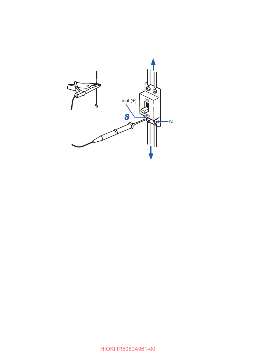
If there is no insulation deterioration in the measurement for the N
8
terminal side, connect the red test lead to the P terminal on the PV string
side and repeat steps 5 to 7.
Power conditioner, main switch
(Black)
P terminal (+)
Disconnector
Ground terminal
After the end of measurement
After the insulation resistance of all PV strings has been measured,
1
disconnect the black test lead from the ground terminal.
Reconnect any lightning arresters that were disconnected.
2
Turn on the disconnectors for all PV strings.
3
Turn on the main switch in the connection box.
4
8
(Red)
N terminal (−)
String
58
Page 59
4
HIOKI IR5050A961-00
For PV insulation resistance measurement, timer test can only be performed.
Insulation Diagnosis Functions
4.1 TIMER Function (Timer Test)
Used to set the instrument to automatically stop the test at a specied time.
If the timer is set during insulation resistance measurement, the measurement
automatically ends at the set time.
Setting range: 10 sec. to 99 min.
Setting method
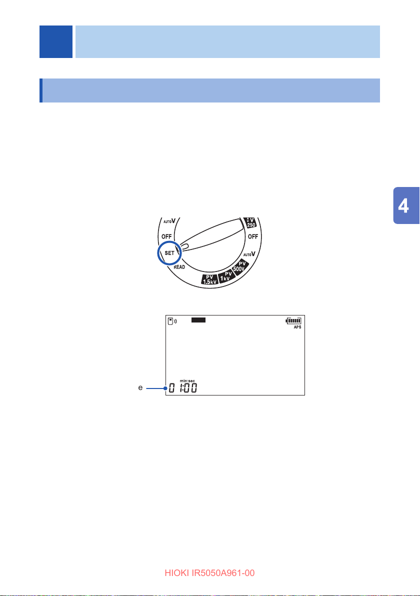
Turn the rotary switch to SET.
1
Press the MODE key and select the [TIMER] display.
2
TIMER
Press the key or the key to set the numerical value.
3
The time indication will blink. Hold down a key for fast increase/decrease of the
numerical value.
Press the ENTER key to conrm.
4
Set time
59
Page 60
TIMER Function (Timer Test)
HIOKI IR5050A961-00
Using timer
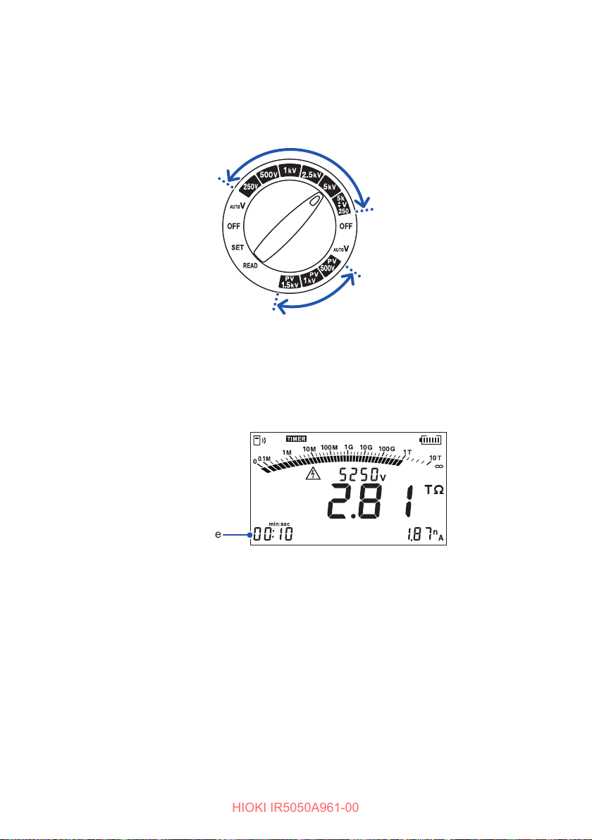
Turn the rotary switch to one of the following .
1
• Insulation resistance measurement: between 250 V and
• PV insulation resistance measurement: PV500V, PV1kV, or PV1.5kV
Press the MODE key and select the [TIMER] display.
2
The timer is set.
Measure insulation resistance.
3
See “3.3 Measuring Insulation Resistance” (p. 41).
The remaining time appears during the measurement.
▲
V
2505k
▼
After the set time has elapsed, the instrument automatically stops measurement.
If the MEASURE key is pressed, the instrument immediately stops
measurement regardless of the remaining time.
When the timer is set, the automatic power save function is disabled.
When measuring for 1 min. or more, the 1-min. value can be displayed with the
or key, either during or after measurement.
60
Remaining time
Page 61
PI (Polarization Index) and DAR (Dielectric Absorption Ratio) Measurement
HIOKI IR5050A961-00
4.2 PI (Polarization Index) and DAR (Dielectric Absorption Ratio) Measurement
Used to check whether insulation resistance increases with time after a voltage is
applied.
The instrument automatically calculates and displays PI*
2
(dielectric absorption ratio), which are used as the criteria to determine the
DAR*
quality of insulation. Both measurements show a degree of change in insulation
resistance with time after a test voltage is applied.
When the PI value or the DAR value is less than 1, the instrument determines that the
insulation of the object under measurement is deteriorated. The PI value and DAR
value are not dependent on temperature because the temperature of the insulating
material does not vary by a large degree during measurement.
See “9.4 Example of PI (Polarization Index) Criteria” (p. 123).
*1. Polarization Index
If the obtained measured value of insulation resistance is greater than 5000
one minute after voltage was applied, the PI value is not recommended in
M
Ω
IEEE 43 because it may not be the insulation diagnosis index.
*2. Dielectric Absorption Ratio
DAR is used when the measured value stabilizes within one minute.
1
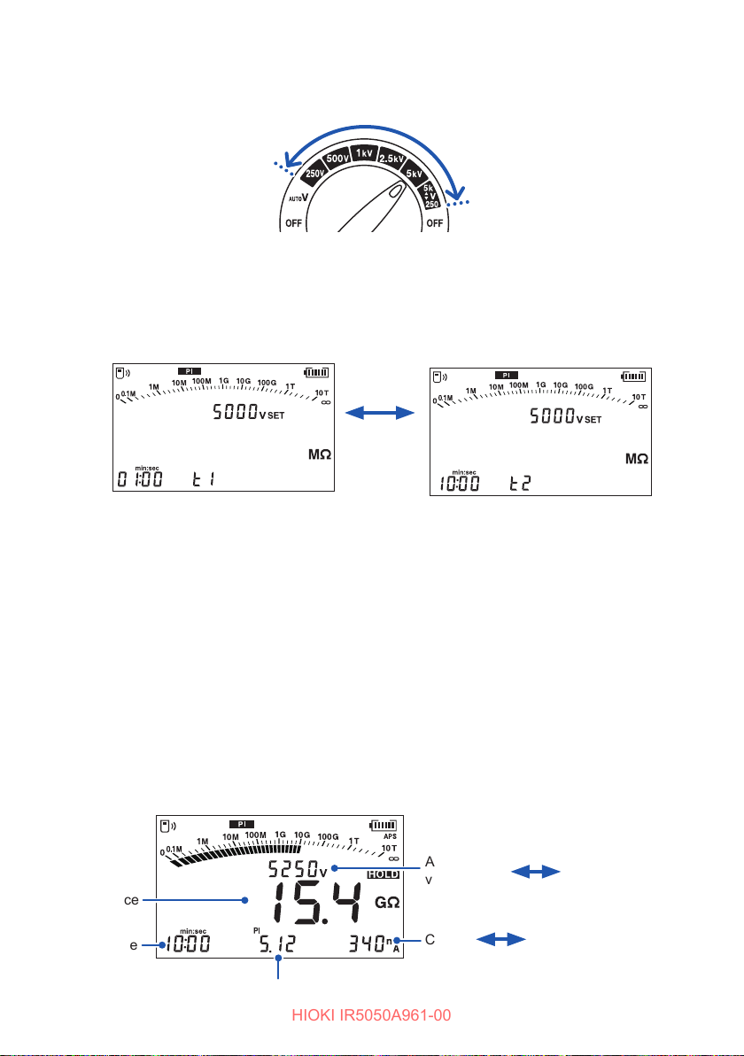
(polarization index) and
Overview of test
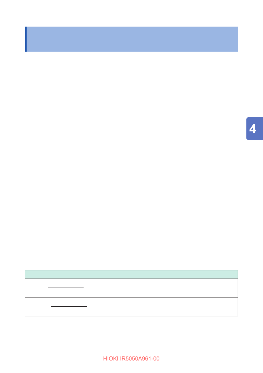
The results are calculated with the following formula from the resistance after the
specied amounts of time (t
resistance measurement.
The specied amounts of time (t
See “4.6 Changing Settings for the Insulation Diagnosis Functions” (p. 70).
PI
DAR
t2 resistance t1 = 1 min.
==
t
==
and t2) have elapsed after the start of the insulation
1
and t2) can be set to the desired times.
1
Calculation formula Default value
= 10 min.
resistance
1
t
2
t2 resistance t1 = 30 sec.
= 1 min.
t
resistance
1
t
2
61
Page 62
PI (Polarization Index) and DAR (Dielectric Absorption Ratio) Measurement
HIOKI IR5050A961-00
Turn the rotary switch to one of the selections between 250 V and
1
▲
V
2505k
.
▼
Press the MODE key and select the [PI] or [DAR] display.
2
display appears.
The t
1
Use the or key to display the t
display.
2
Example: PI measurement
Switch
with /
t1 display
Specify amount of time (t1 and t2)
3
t2 display
Setting range: 10 sec. to 99 min.
See “4.6 Changing Settings for the Insulation Diagnosis Functions” (p. 70).
Measure insulation resistance.
4
See “3.3 Measuring Insulation Resistance” (p. 41).
To determine PI, continue measurement for 10 minutes (for the default settings).
To determine DAR, continue measurement for one minute.
Stop measurement.
5
Check the measured value.
6
Use the or key to switch the t
Resistance
Time
PI
display and t2 display.
1
Automatically switches every two seconds.
Actual output
voltage
Current
Static capacitance
Set voltage
62
Page 63
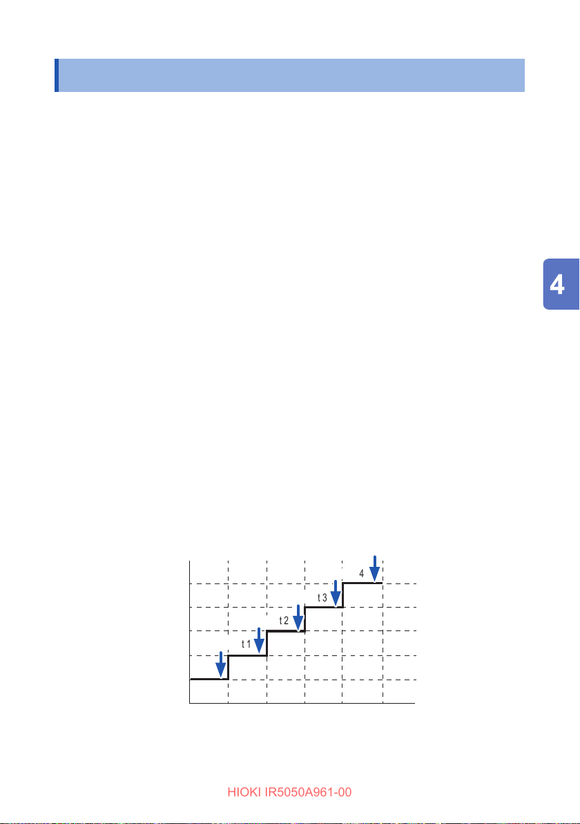
SV Measurement (Step Voltage Test)
HIOKI IR5050A961-00
4.3 SV Measurement (Step Voltage Test)
Used to determine whether the insulation resistance of an object under measurement
is aected by a change in test voltage.
The step voltage test is based on the following principle: An ideal insulating material
shows the same resistance at all voltages. And the resistance of a deteriorated
insulating material decreases when the applied voltage increases.
If the insulation resistance decreases as the test voltage increases, the object under
measurement is damp or unclean and requires attention.
(Reference standard: IEEE 95)
Overview of test
• The test voltage is increased in 5 steps of 20% each at regular intervals during
insulation resistance measurement. The resistance and current are measured once
at the end of every step.
• The voltage is increased when one minute has passed per step. When 5 minutes
has passed in total, measurement automatically stops (default setting).
The voltage application time per step can be changed. However, the voltage
application time cannot be varied for each step.
See “4.6 Changing Settings for the Insulation Diagnosis Functions” (p. 70).
Example:
When set to test voltage: 5 kV and voltage application time per step: 1 min.
Order of applied voltage: 1 kV → 2 kV → 3 kV → 4 kV → 5 kV
5 kV
4 kV
3 kV
2 kV
1 kV
Measurement 5
Measurement 4
Measurement 3
Measurement 2
Measurement 1
1 min. 2 min. 3 min. 4 min. 5 min.
63
Page 64
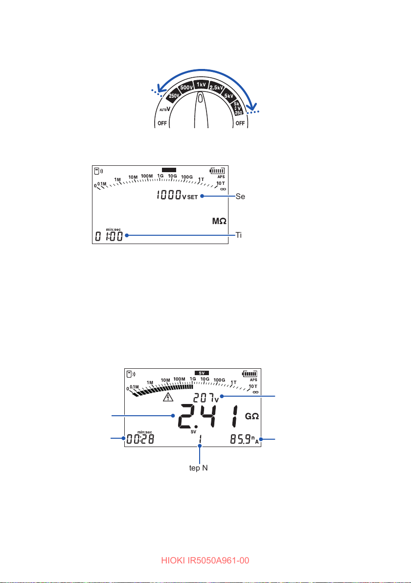
SV Measurement (Step Voltage Test)
HIOKI IR5050A961-00
Turn the rotary switch to one of the selections between 250 V and
1
▲
V
2505k
.
▼
Press the MODE key and select the [SV] display.
2
SV
Set voltage
Time per step
Set the time per step.
3
Setting range: 10 sec. to 10 min.
See “4.6 Changing Settings for the Insulation Diagnosis Functions” (p. 70).
Measure insulation resistance.
4
See “3.3 Measuring Insulation Resistance” (p. 41).
The test voltage rises each minute (default setting) and the measurement stops
automatically.
Resistance
Elapsed time
The last data is retained and displayed ([HOLD] lights up).
64
Actual output voltage
Current
Step No.
Page 65
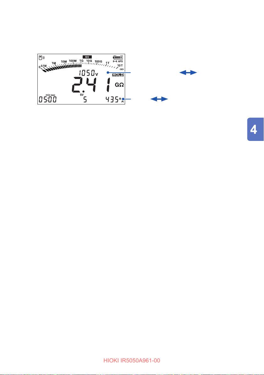
SV Measurement (Step Voltage Test)
HIOKI IR5050A961-00
Check the measured value for each step.
5
Use the or key to switch to the data display for each step.
Automatically switches every two seconds.
Actual output voltage
Current
Static capacitance (step 5 only)
Set voltage
65
Page 66
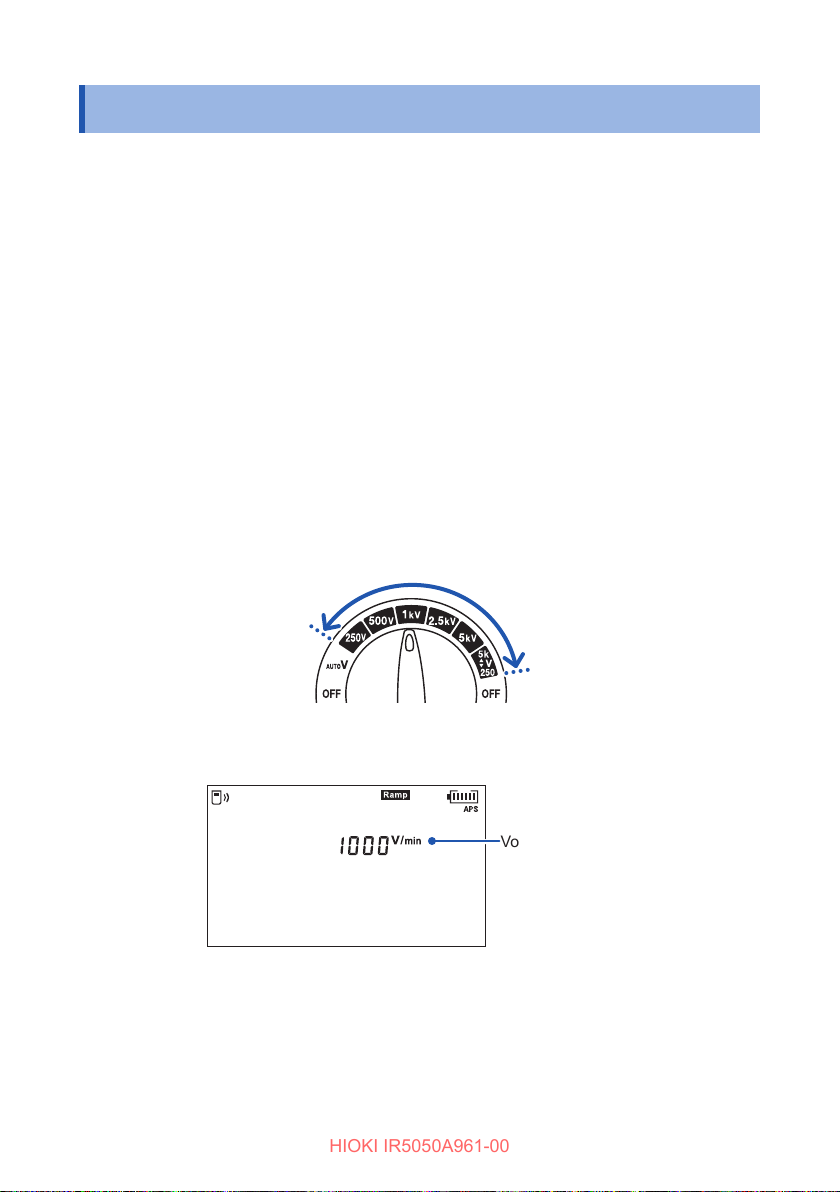
Ramp Measurement (Ramp Voltage Test)
HIOKI IR5050A961-00
4.4 Ramp Measurement (Ramp Voltage Test)
Used to determine whether the insulation resistance of an object under measurement
is aected by a change in test voltage, in the same manner as the step voltage test.
This test subjects the object under measurement to less stress than the step voltage
test because the test voltage is continuously increased in a gradual manner.
(Reference standard: IEEE 95)
Overview of test
The applied voltage in the insulation resistance measurement is gradually raised until
it reaches the set voltage. The measurement automatically ends once the applied
voltage reaches the set voltage.
Default setting: 1000 V/min
See: “4.6 Changing Settings for the Insulation Diagnosis Functions” (p. 70)
Turn the rotary switch to one of the selections between 250 V and
1
▲
V
2505k
.
▼
Press the MODE key and select the [Ramp] display.
2
Set the voltage rise value.
3
Setting range: 100 V/min to 9000 V/min
See: “4.6 Changing Settings for the Insulation Diagnosis Functions” (p. 70)
66
Voltage rise setting
Page 67
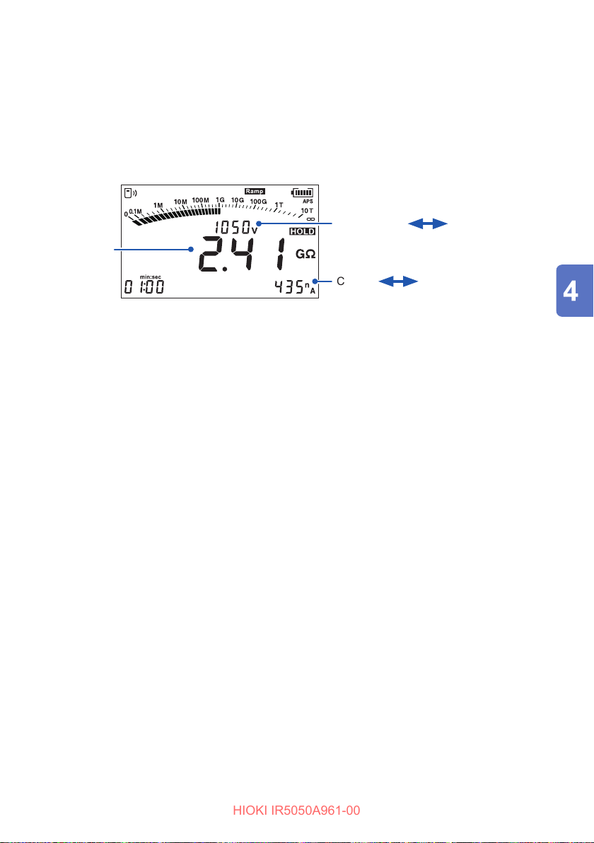
Ramp Measurement (Ramp Voltage Test)
HIOKI IR5050A961-00
Measure insulation resistance.
4
See: “3.3 Measuring Insulation Resistance” (p. 41)
The test voltage gradually rises and the measurement stops automatically when
the set voltage is reached.
Check the measured value.
5
Automatically switches every two seconds.
Resistance
Actual output
voltage
Current
Voltage rise
setting
Static capacitance
67
Page 68
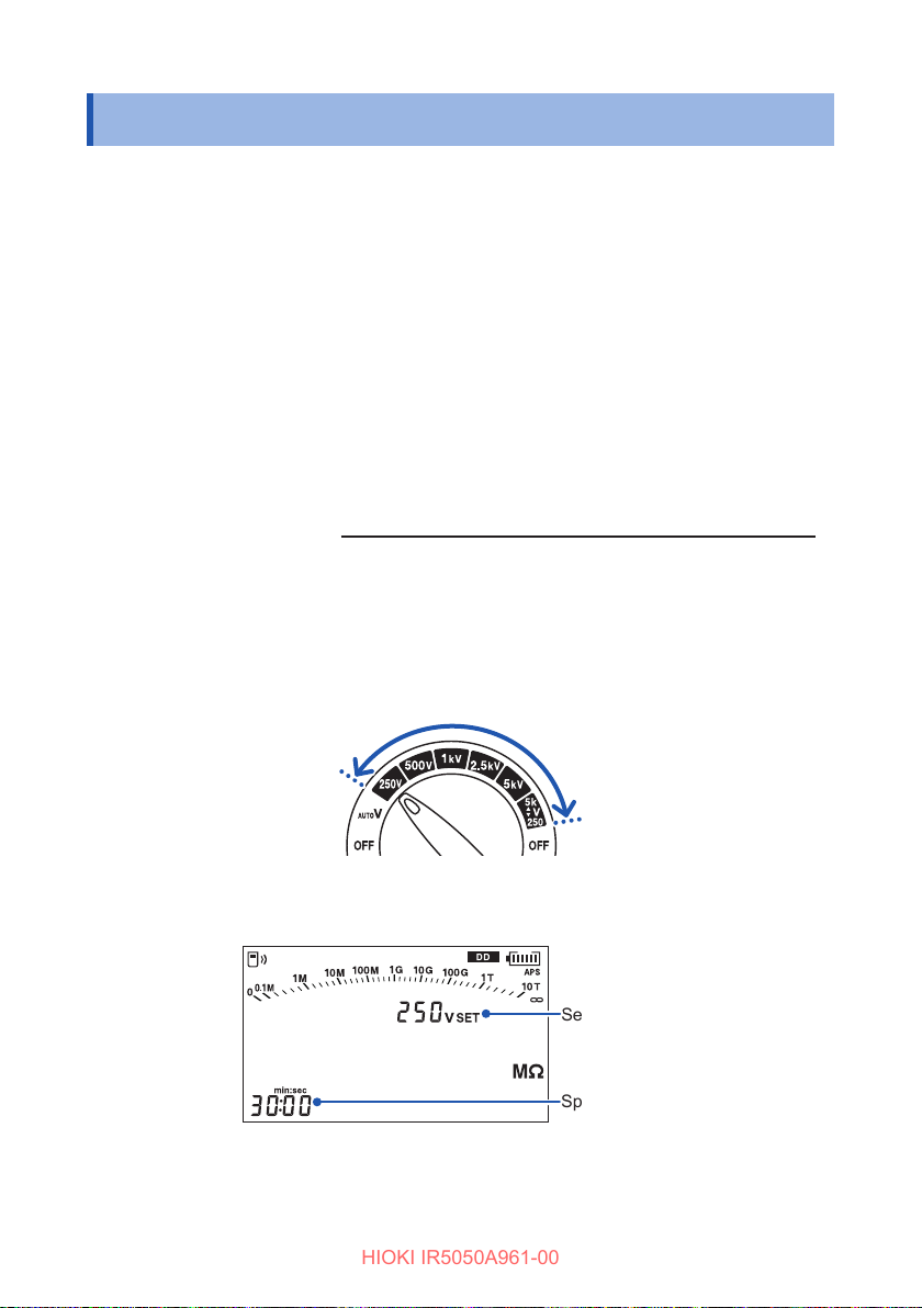
DD Measurement (Dielectric Discharge)
HIOKI IR5050A961-00
4.5 DD Measurement (Dielectric Discharge)
Used to diagnose a multi-layer insulator.
Since the result of this test is dependent on discharge characteristics, the internal
condition of the insulating material can be tested with little regard to surface
contamination. When the condition of the insulating material is good, the instrument
displays a DD value of less than 2.
Overview of test
The result is calculated with the following formula by performing the insulation
resistance measurement for the specied time and then using the discharge current
one minute after the measurement has ended and the capacitance of the object
under measurement.
DD (dielectric discharge)
Default setting: 30 min.
See: “4.6 Changing Settings for the Insulation Diagnosis Functions” (p. 70)
==
Current 1 min. after end of measurement (nA)
Voltage at end of measurement (V)
Capacitance (μF)
×
Turn the rotary switch to one of the selections between 250 V and
1
▲
V
▼
Press the MODE key and select the [DD] display.
2
68
2505k
.
Set voltage
Specied time
Page 69
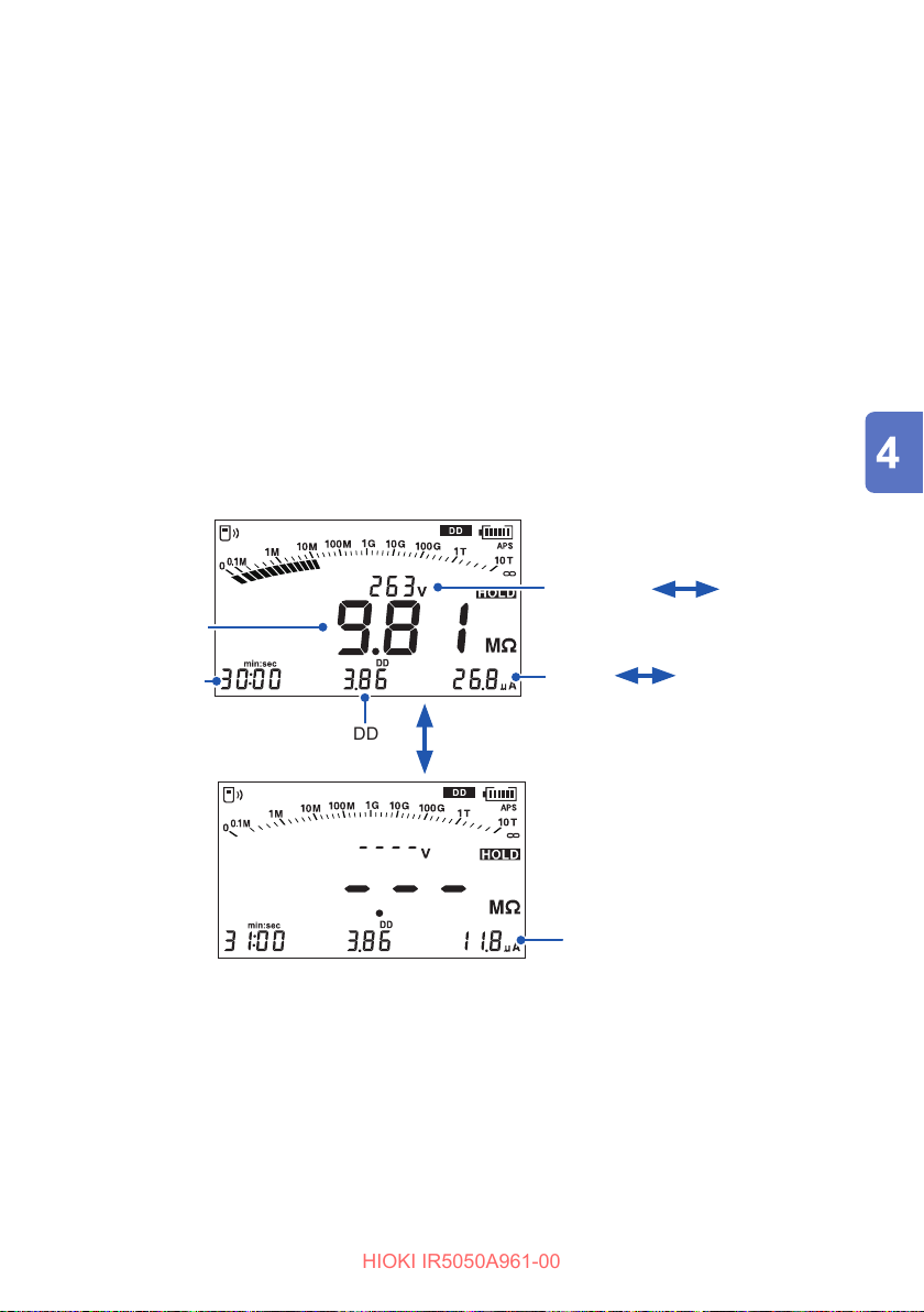
DD Measurement (Dielectric Discharge)
HIOKI IR5050A961-00
Specify the amount of time.
3
Setting range: 10 sec. to 98 min.
See: “4.6 Changing Settings for the Insulation Diagnosis Functions” (p. 70)
Measure insulation resistance.
4
See: “3.3 Measuring Insulation Resistance” (p. 41)
After the set time has elapsed (default setting: 30 min.), the instrument
automatically stops voltage generation.
The measurement continues for one minute after voltage generation is stopped.
Check the measured value.
5
The current value 1 min. after measurement completes can be checked with the
or key.
Automatically switches
every two seconds.
Resistance
Measurement
end time
DD
Actual output
voltage
Current
Use the or key to switch to the display.
Set voltage
Static capacitance
after 1 min.
Current
after 1 min
69
Page 70
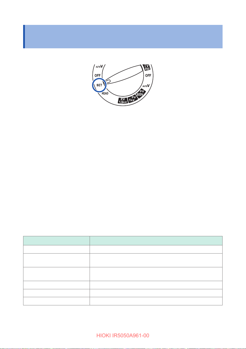
Changing Settings for the Insulation Diagnosis Functions
HIOKI IR5050A961-00
4.6 Changing Settings for the Insulation Diagnosis Functions
Turn the rotary switch to SET.
1
Press the MODE key and select the display for the function to check or
2
change.
Each time the MODE key is pressed, the display changes in the following order.
[COMP] (p. 71) → [TIMER] → [PI] → [DAR] → [SV]→ [Ramp] → [DD] →
returns to [COMP]
Press the key or the key to change the setting.
3
For [PI] and [DAR], use the or key to switch between [t1] and [t2].
The setting being changed will blink.
Press the CLR key while the setting is blinking to reset it to the default value.
Press the ENTER key to conrm.
4
Setting ranges of the insulation diagnosis functions
Function Setting range (default setting)
TIMER 10 sec. to 99 min.(1 min.)
PI
DAR
SV 10 sec. to 10 min. (1 min.)
Ramp 100 V/min. to 9000 V/min. (1000 V/min.)
DD 10 sec. to 98 min. (t = 30 min.)
*1. t1 must be set to a value less than t2. If the setting of t1 cannot be increased, rst
to a value larger than t1, and then set t1.
set t
2
70
10 sec. to 99 min.(t
Setting condition*1: t2 > t
10 sec. to 99 min. (t1 = 30 sec. and t2 = 1 min.)
Setting condition*1: t2 > t
= 1 min. and t2 = 10 min.)
1
1
1
Page 71
5
HIOKI IR5050A961-00
Other Functions
5.1 Comparator Function
This function compares the measured value against a preset value and makes a
pass/fail judgment.
The comparator function is limited by the measurement and insulation diagnostic
functions.
Available: , not available:
Measurement functions
Insulation diagnosis
functions
– (no diagnosis function)
Timer test
Polarization index
Dielectric absorption ratio
Step voltage test
Ramp voltage test
Dielectric discharge
Insulation resistance
measurement
Voltage
measurement
–
–
– –
– –
– –
– –
– –
PV insulation resistance
measurement (IR5051 only)
–
The comparator function operates as follows.
Judgment condition
Measured value ≥ reference value
Measured value < reference value
Reference value setting range: 0.1 MΩ to 100 GΩ/O
Default setting: O
Result
Pass
Fail
Display Backlight Beeping
No change Intermittent
Lights up in red Continuous
71
Page 72
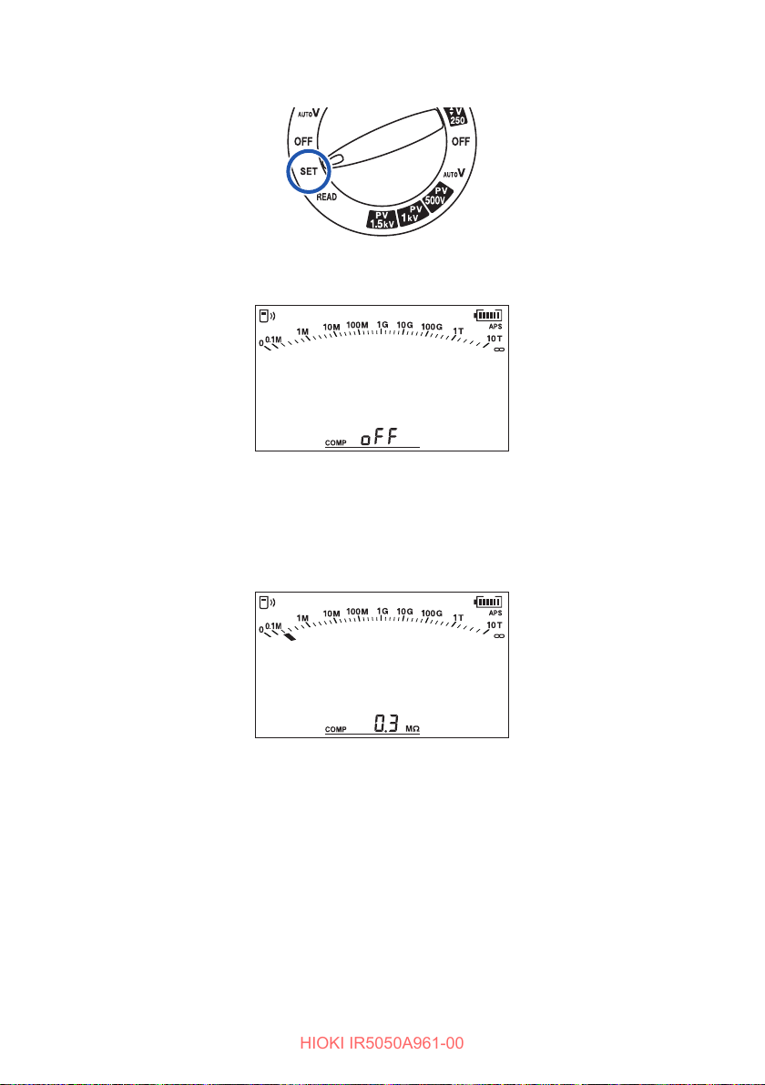
Comparator Function
HIOKI IR5050A961-00
Turn the rotary switch to SET.
1
The setting screen for the comparator appears.
The default setting is O.
Press the key or the key to set the reference value.
2
The setting being changed will blink.
Disable the comparator function when it is not used.
Press the CLR key while changing to the setting to set to OFF.
Press the ENTER key to conrm.
3
The comparator setting is saved even when the power is turned o.
72
Page 73
Automatic Power Save Function
HIOKI IR5050A961-00
5.2 Automatic Power Save Function
This function can save battery consumption.
The instrument enters the automatic power save state and turns o the LCD after
approximately 10 minutes from the last operation or from when the live line warning
display (
When the power is turned on, the automatic power save function is enabled
automatically. ([APS] lights up)
[APS] will start blinking around 30 seconds before the instrument enters the
automatic power save state.
Recovering from the automatic power save state
Use the rotary switch to turn the power o and on again. The LCD lights up and the
instrument recovers from the automatic power save state.
Disabling automatic power save function
Use the rotary switch to turn o the power, and then while holding down the MODE
key, use the rotary switch to turn on the power to cancel the automatic power save
function.
) was last lit or blinking.
IMPORTANT
The automatic power save function setting is not saved when the power is turned
o.
73
Page 74

Wireless Communications Function (GENNECT Cross)
HIOKI IR5050A961-00
5.3 Wireless Communications Function (GENNECT Cross)
Turn on the wireless communications function to check the measurement data saved
in the instrument’s memory and create measurement reports with a mobile device.
For details, see the GENNECT Cross website.
Install the Z3210 wireless adapter (option) in the instrument.
1
See: “2.2 Installing the Z3210 Wireless Adapter” (p. 31)
Install GENNECT Cross on the mobile device.
2
Turn on the instrument’s power.
3
When the power is rst turned on after the Z3210 is installed, the wireless
communications function is turned on automatically.
Hold down the MODE key and the MEM key for more than one second to
4
turn on the wireless communications function.
When the wireless communications function is turned on,
LCD.
Blinking: Connected to a mobile device
Lit: Communications function is on
Not lit: Communications function is o
To turn on/o the wireless communications function, hold down the MODE key
and the MEM key for more than one second.
Start GENNECT Cross and register the connection with the instrument.
5
Select a function and take the measurement.
6
appears in the
• The communications distance is approximately 10 m line of sight. The distance at
which communications is possible will vary greatly by the distance between the
instrument and any obstacles (for example, walls or metal shielded objects) and the
oor (ground). Conrm that the strength of the radio waves is sucient for stable
communications.
• GENNECT Cross is available free of charge. However, any internet connection
charges incurred when downloading and using the application software are the
responsibility of the customer.
• GENNECT Cross may not run correctly depending on the mobile device.
74
Page 75

Wireless Communications Function (GENNECT Cross)
HIOKI IR5050A961-00
• The Z3210 uses wireless technology in the 2.4-G Hz band. If the instrument is close
to a device that uses the same frequency band, such as a wireless networking
device (IEEE 802.11.b/g/n), it may not be possible to establish communications.
• When GENNECT Cross is rst started (i.e., there are no registered devices), it
starts with the connection settings screen.
• On the GENNECT Cross connection settings screen, the connection to the
instrument is automatically registered if the instrument is close (up to eight
instruments).
• Wait 5 to 30 seconds from when the instrument’s power is turned on until the
connection to the instrument is registered. If the instrument is not registered even
after waiting for 1 minute, restart GENNECT Cross and the instrument.
75
Page 76
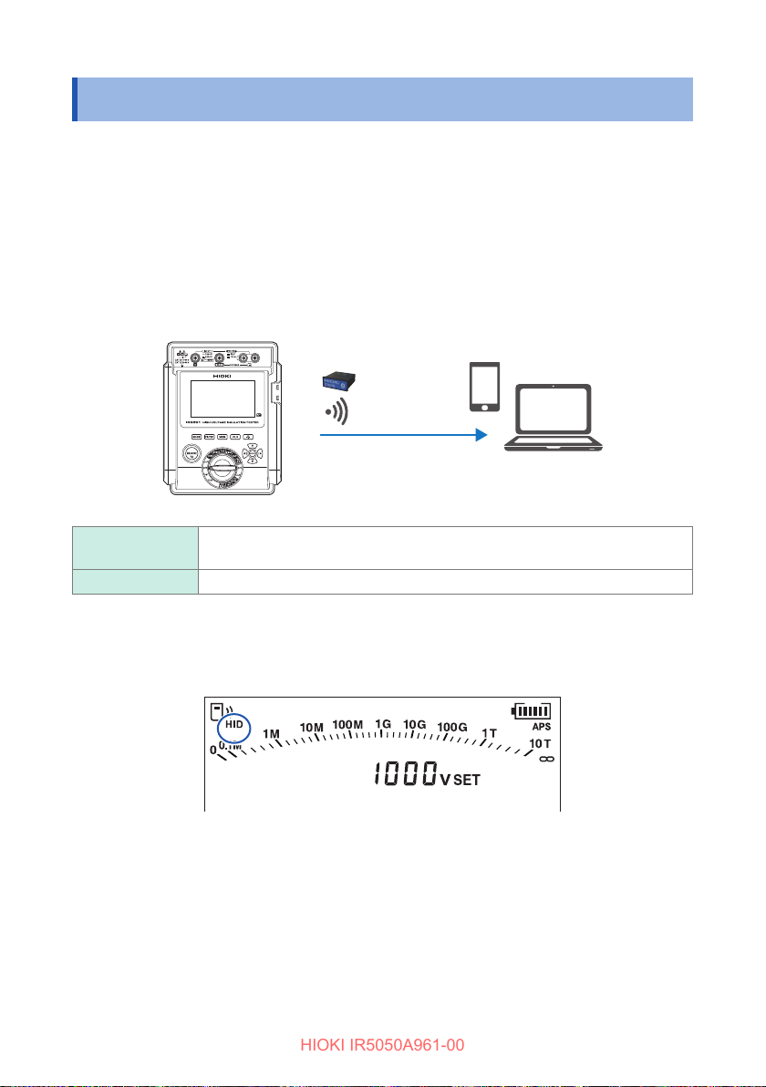
Excel Direct Input Function (HID Function)
HIOKI IR5050A961-00
5.4 Excel Direct Input Function (HID Function)
HID (human interface device prole) is a function the Z3210 wireless adapter is
equipped with and is a prole that allows the instrument to operate in the same
manner as a wireless keyboard.
GENNECT Cross (p. 74) and the HID function cannot be used at the same time.
The instrument will stand by with an Excel le opened on a mobile device or PC and
a cell selected. When the instrument’s display is retained, the measured value can be
entered in the selected cell.
HID ON Measured values can be entered in an Excel le or text le.
Communications with GENNECT Cross are not possible.
HID OFF Select o when using GENNECT Cross.
Checking the HID setting
The HID function is on when [HID] is lit on the LCD.
Turning HID function on/o
The HID on/o setting is saved in the Z3210. The setting is not saved in the
instrument.
Turn o the power by turning the rotary switch to OFF.
1
76
Page 77
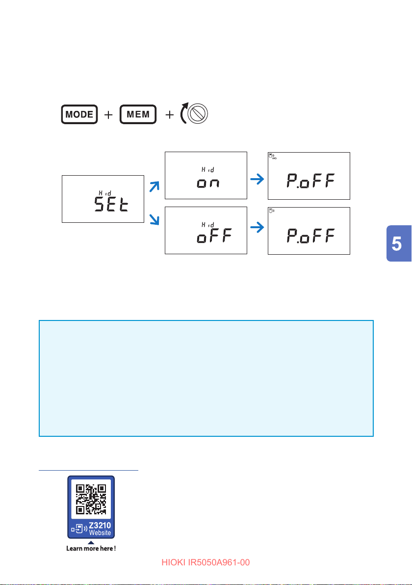
Excel Direct Input Function (HID Function)
HIOKI IR5050A961-00
Install the Z3210 wireless adapter (option) in the instrument.
2
See: “2.2 Installing the Z3210 Wireless Adapter” (p. 31)
While holding down the MODE key and the MEM key, turn the rotary
3
switch to turn on the power.
(Any position)
After the setting appears, the power is turned o automatically.
PI DAR SV
TCPIDARSVDD
COMP
Ramp
DD
Year
MEMORY
No.
READ
LOGGING
USED
TIMER
HID
Month Day
FILTER
NOISE
hr:min:sec
When [oLd] appears
Use GENNECT Cross (version 1.8 or later) and update the Z3210 to the latest
version.
IMPORTANT
To switch from the HID function to GENNECT Cross
If GENNECT Cross is started without unpairing the mobile device and instrument,
the instrument may not be recognized as a connected device.
Use the following procedure and connect the instrument to GENNECT Cross again.
1. From the Bluetooth® settings for your mobile device, delete the instrument.
2. Turn o the Z3210’s HID function.
In the GENNECT Cross connected instrument settings, reconnect the instrument.
3.
For details, see the Z3210 website.
https://z3210.gennect.net
77
Page 78
Version Upgrade Function
HIOKI IR5050A961-00
5.5 Version Upgrade Function
You can use GENNECT Cross (free application software) to upgrade the rmware in
the instrument. For details, see the GENNECT Cross usage guide.
Conditions
GENNECT Cross Version 1.8 or higher
See “5.7 Power On Options List” (p. 82) to check the current version.
78
Page 79
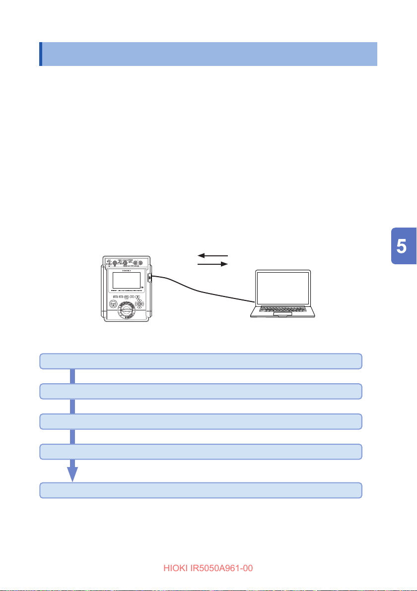
Communicating with PC
HIOKI IR5050A961-00
5.6 Communicating with PC
Data saved in the memory may be downloaded to a PC and the instrument settings
may be changed from a PC by using the DT4900-01 communication package (option)
and Hioki Sequence Maker*
memory or create a report.
When performing communications with the DT4900-01, you cannot measure
insulation resistance, leakage current, or voltage. The DT4900-01 cannot be used
with this instrument to control measurement.
*1. Sequence Maker is an Excel add-in provided by Hioki for no additional charge. It
allows communications and control with the instrument using simple operations
that involve entering communications commands in an Excel worksheet, so no
programming experience is required.
1
. Used to make a table or graph of the data stored in the
Control instrument
Download data
Install the USB driver on the PC (p. 80)
Install the Sequence Maker on the PC (p. 80)
Installing the Instrument Memory Download Tool (p. 80)
Install the communications adapter in the instrument (p. 81)
Connect the instrument to the PC
79
Page 80
Communicating with PC
HIOKI IR5050A961-00
A virtual COM port on the PC is used for the USB interface. The virtual COM ports
the instrument can recognized on are COM1 to COM256.
Communications method Asynchronous serial communications over infrared (half duplex)
Content Data saved in the instrument’s memory
Speed 9600 bps
Data length 8 bits
Stop bit 1
Parity bit None
Delimiter CR+LF
Installing the USB driver
Before connecting the instrument to a PC for the rst time, be sure to install the
special USB driver on the PC. The USB driver can be downloaded from the software
download page at Hioki’s website.
https://www.hioki.com/global/support/download/software/
Installing the Sequence Maker
Before connecting the instrument to a PC for the rst time, be sure to install
Sequence Maker on the PC. You can download this software from the following
special Sequence Marker website.
For details on the operating procedures and other information, see the website.
https://sequencemaker.hioki.com/
Installing the Instrument Memory Download Tool
You can use communications commands and the Instrument Memory Download Tool
to change the settings in the instrument and to retrieve saved data.
A list of communications commands can be found in the Instrument Memory
Download Tool le.
Download the Instrument Memory Download Tool from the software download page
at Hioki’s website.
https://www.hioki.com/global/support/download/software/
80
Page 81
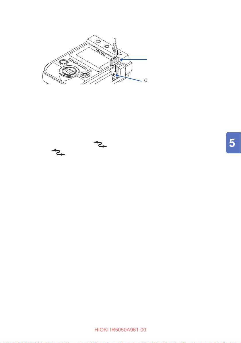
Communicating with PC
HIOKI IR5050A961-00
Installing the communications adapter in the instrument
USB cable
Communications adapter
Communications port
Install the communications adapter in the instrument.
1
Connect a USB cable to the communications adapter.
2
Communicate with the instrument using communications commands and
3
the Instrument Memory Download Tool.
• Connect the cable in the correct direction.
• During communications, the
• When the
• Do not disconnect the USB cable during communications.
• When the wireless communications function (GENNECT Cross) is on,
communications cannot be performed using the DT4900-01. To use the DT4900-
01, turn o the wireless communications function or remove the Z3210.
mark is lit, the instrument’s operation keys are disabled.
mark appears on the LCD.
81
Page 82
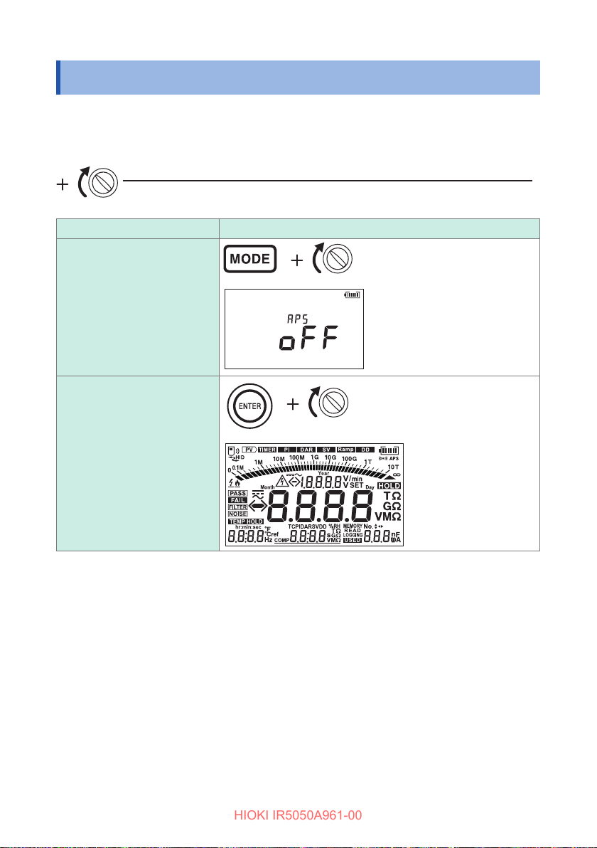
Power On Options List
HIOKI IR5050A961-00
5.7 Power On Options List
You can change and check the instrument’s system settings.
The instrument changes to the measurement screen if the operation key is released.
Turn o power, and then turn on power while holding down operation key
(Turn rotary switch from OFF position)
Details Method/Display
(Any position)
Disable automatic power
save function
(Any position)
Display fully lit LCD, live line
warning, and backlight lit in
82
white
Page 83
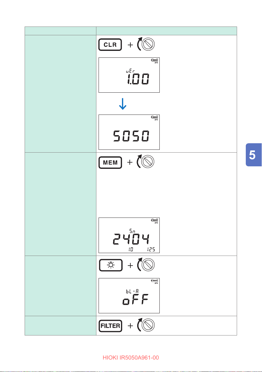
Details Method/Display
HIOKI IR5050A961-00
Display software version
and model name
Display serial number
Power On Options List
(Any position)
Software version
Display changes after one second.
Model name
(Any position)
The serial number consists of nine digits. The rst two digits
indicate the year of manufacture, while the second two digits
indicate the month of manufacture.
The following screen indicates the instrument was
manufactured in April 2024.
Serial number: 240410125
Enable or disable backlight
automatic-o function
Disable hardware lter
function
(Any position)
(Any position)
83
Page 84
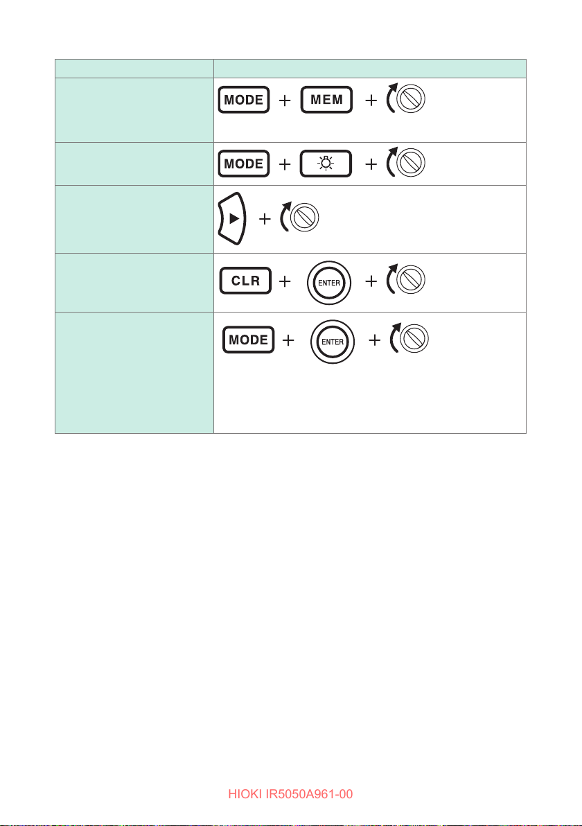
Power On Options List
HIOKI IR5050A961-00
Details Method/Display
Turn HID function on/o
(When the Z3210
is installed only)
(p. 76)
(Any position)
The HID on/o setting is saved in the Z3210.
Fix the voltage measurement
to DCV
Negative voltage notication
function on/o
(IR5051 only)
(p. 52)
System reset
(p. 118)
Keep insulation diagnostics
function (p. 59) enabled
(Any position)
(Any position)
(Any position)
The user can select whether to keep the insulation diagnostic
function enabled even if the instrument is turned o.
[USEr SET on] Keep enabled
[USEr SET oFF] Do not keep enabled
(Any position)
84
Page 85
Recording Measurement Data
HIOKI IR5050A961-00
6
(Data Memory Function)
The instrument stores measurement data, settings, date, time, temperature, and
humidity in the internal memory.
The data memory function can be used in insulation resistance measurements.
The recorded data is saved even when the power is turned o.
There are two recording methods. (Combinable)
Manual recording Records the measured value retained on the display.
Logging recording
• Logging recording can be used in insulation resistance measurement and PV
insulation resistance measurement. For insulation diagnosis functions, timer test
can only be used (p. 88).
• The content of a manual record is viewed on the display of the instrument. The
recorded data can also be downloaded to a PC using the DT4900 communications
package (option).
• For logging records, only the last value is viewed on the display of the instrument.
The entire record is viewed on a PC using Sequence Maker.
See: “5.6 Communicating with PC” (p. 79)
• Add memory number to data to record. The memory number serves as the address
in the memory. The recording methods and conguration of memory number are
shown below.
Recording method Memory number
Manual recording
Logging recording Lr0 - Lr9 (10 numbers in total. Up to 60 minutes of logging per data)
Records the measured value at each set recording interval.
(Set the recording interval or timer before measurement.)
A00 - A99, B00 - B99, C00 - C99, D00 - D99, E00 - E99, F00 - F99,
H00 - H99, J00 - J99, N00 - N99, P00 - P99
(1000 numbers in total)
85
Page 86
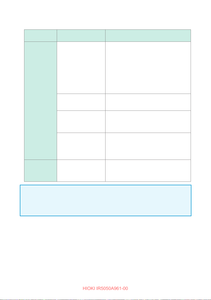
HIOKI IR5050A961-00
• The table below shows storable data.
Recording
method
Manual
recording
Logging
recording
Type of data Data stored in one record
Memory number, date/time, elapsed time,
temperature, humidity, set voltage, actual
output voltage, resistance (nal value),
Standard measurement
data
SV (step voltage) data
Ramp (ramp voltage test)
data
DD (dielectric discharge)
data
–
resistance (1-min. value), PI value, PI or DAR
set time (t
set time (t1), and resistance set time (t2)
(Even if PI is not selected as the function, PI
is saved as the default setting. If the function
is DAR, the DAR settings are saved instead of
PI.)
Memory number, date/time, elapsed time,
temperature, humidity, set voltage (maximum
value), actual voltage
Memory number, date/time, elapsed time,
temperature, humidity, set voltage (maximum
value), actual voltage, resistance (nal value),
and voltage rise setting
Memory number, date/time, elapsed time,
temperature, humidity, set voltage, actual
output voltage, resistance (nal value),
DD value, current 1 min. after end of
measurement, and capacitance
Memory number, date/time, measurement
interval, temperature, humidity, set voltage,
actual output voltage
resistance × number of times
), PI or DAR set time (t2), resistance
1
×
×
5, and resistance × 5
number of times, and
IMPORTANT
• In step voltage test resistance measurements, only the last measurement at the
end of each step is recorded.
• Voltage measurement data cannot be recorded.
86
Page 87
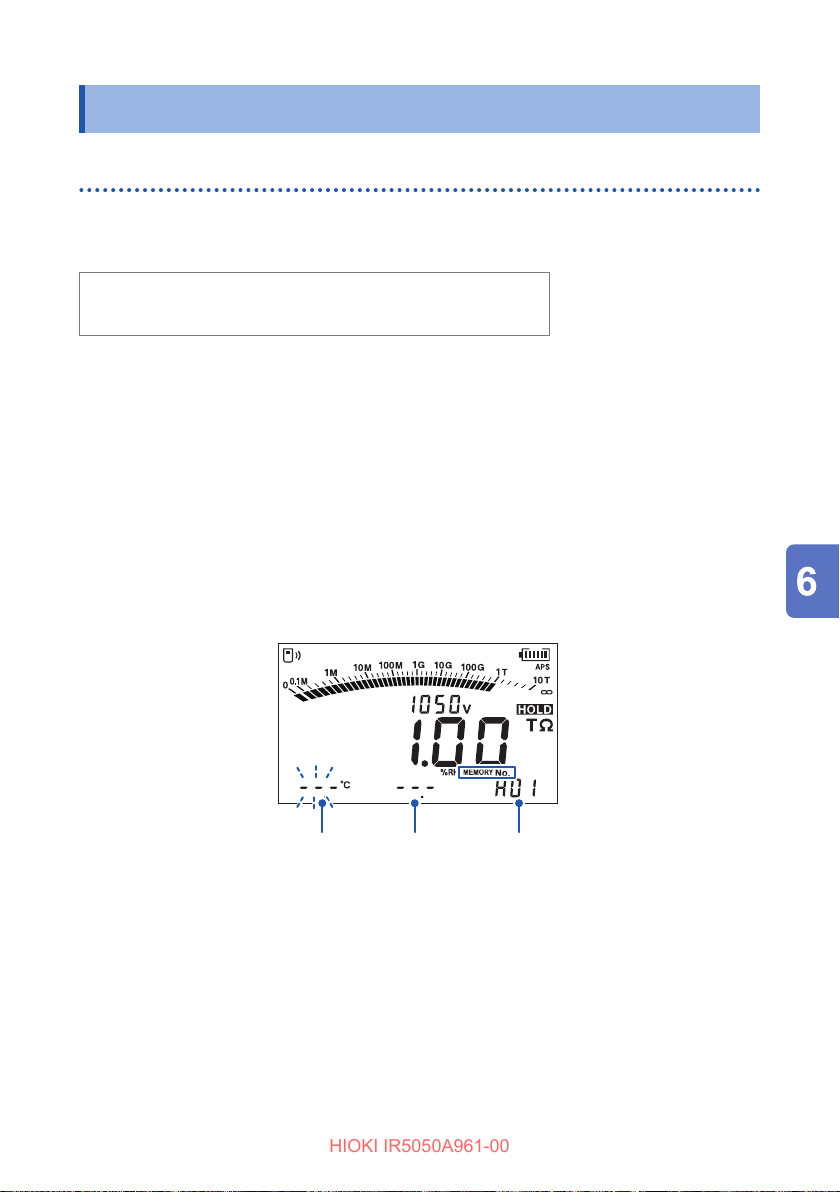
Recording Measurement Data
HIOKI IR5050A961-00
6.1 Recording Measurement Data
Manual recording (recording result of one measurement session)
The memory numbers available for manual recording are divided into the following 10
groups (100 records per group), thus up to 1000 records can be stored.
A00 - A99, B00 - B99, C00 - C99, D00 - D99, E00 - E99,
F00 - F99, H00 - H99, J00 - J99, N00 - N99, P00 - P99
1
There are the following four types of data: standard measurement data, SV data*
Ramp data, and DD data. These four data sets are stored separately.
*1. If step voltage test is stopped at any time, data cannot be recorded.
Measure insulation resistance and stop.
1
See: “3.3 Measuring Insulation Resistance” (p. 41)
If step voltage test is stopped at any time, data cannot be recorded.
Press the MEM key.
2
[MEMORY No.] and the number next to the last stored number appear, and the
setting item blinks.
,
Set the temperature, humidity, and memory number.
3
key or key: Changes the digit
key or key: Changes the value
ENTER key: Conrm
Each press of the ENTER key moves to the next setting item in the following
order.
Temperature → Humidity → Memory number
Temperature
Humidity
Memory No.
87
Page 88
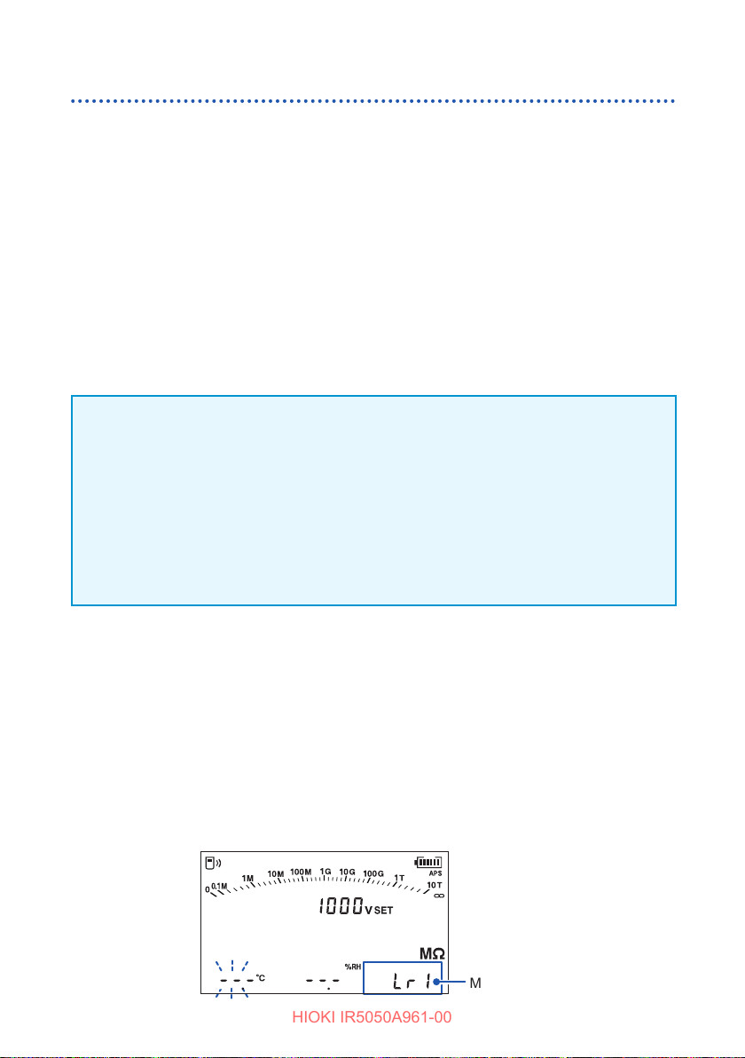
Recording Measurement Data
HIOKI IR5050A961-00
Logging recording (recording at regular intervals)
• Logging recording can be used in insulation resistance measurement and PV
insulation resistance measurement. For insulation diagnosis functions, timer test
can only be used (p. 88).
• A total of 10 memory numbers are used for logging records; Lr0 to Lr9.
• The maximum recording time per record is 60 minutes.
• The recording intervals that can be set are 5 seconds, 15 seconds, 30 seconds,
1 minute, 2 minutes, and 5 minutes.
• Maximum number of loggings vary depending on set recording interval (when the
timer is set to o).
• When the timer is set, the instrument automatically stops measurement after the
set time has elapsed.
IMPORTANT
• Continuous recording time is determined by the battery charge level.
• If the battery charge level becomes low during measurement, [Lo bAt] appears
and the instrument records only the measurement data to that point.
• When a low resistance is measured, more power is consumed, thus the
instrument may not be able to measure data equal to the maximum number of
loggings.
• The comparator function is disabled during the logging recording.
Set the temperature, humidity, memory number, and recording interval
Turn the rotary switch to one of the following selections.
1
• For insulation resistance: 250 V to
• For PV insulation resistance: PV500V, PV1kV, or PV1.5kV
Set the timer to perform a timer test. (p. 59)
Press the MEM key.
2
[MEMORY No.], [LOGGING], and the memory number next to the last stored
number appear, and the setting item blinks.
88
MEMORY
LOGGING
No.
▲
2505k
V
▼
Memory No.
Page 89
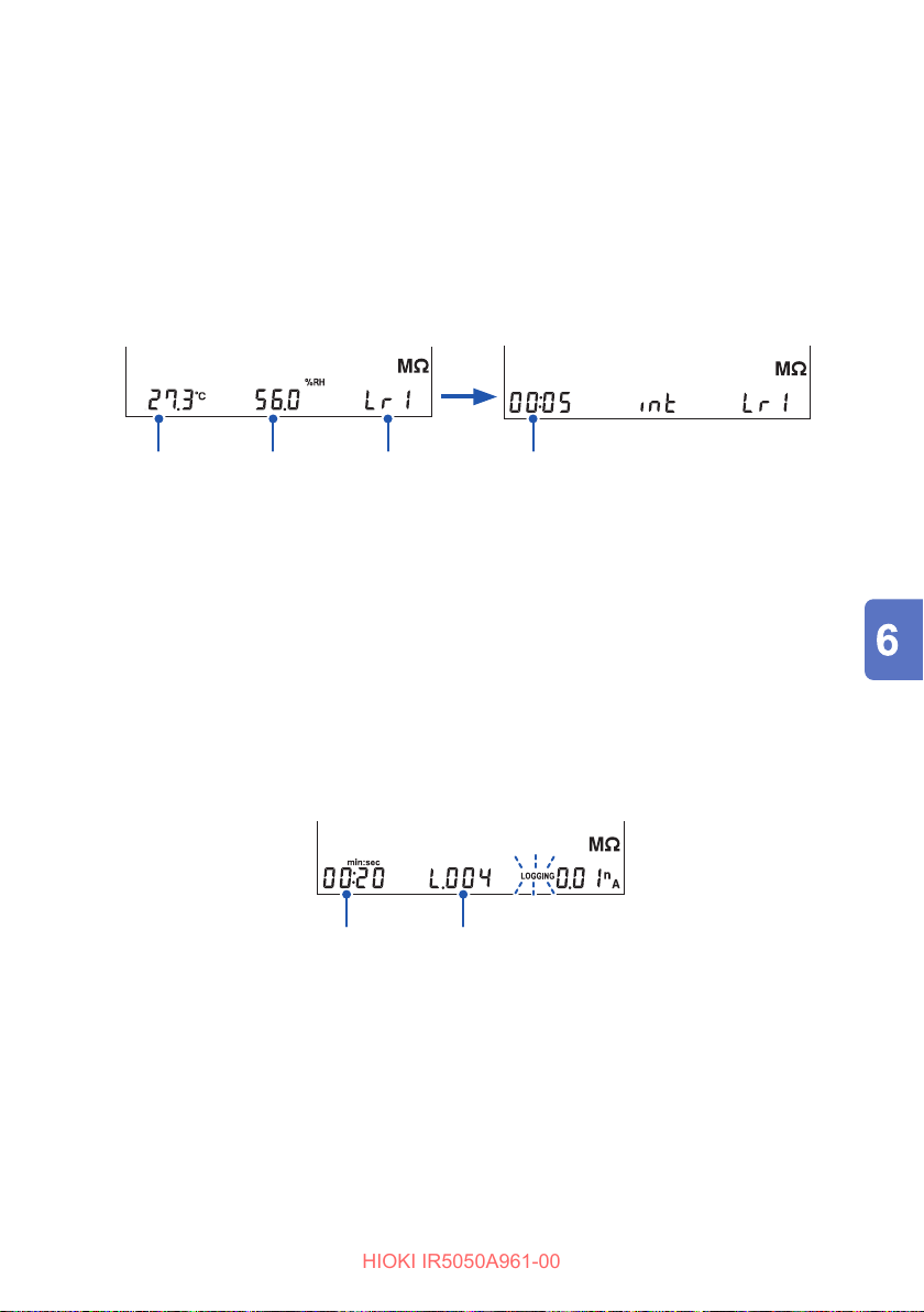
Recording Measurement Data
HIOKI IR5050A961-00
Set the temperature, humidity, memory number, and recording interval.
3
key or key: Changes the digit
key or key: Changes the value
ENTER key: Conrm
Each press of the ENTER key moves to the next setting item in the following
order.
Temperature → Humidity → Memory number → Recording interval
MEMORY
LOGGING
No.
MEMORY
LOGGING
No.
Temperature
Humidity
Memory Number
Recording interval
The instrument is in the measurement standby state.
Measure
Start the insulation resistance measurement.
4
See: “3.3 Measuring Insulation Resistance” (p. 41)
When the measurement is started, [MEMORY No.] and the set memory number
disappear and the measurement display appears.
During measurement, [LOGGING] blinks.
Save processing is executed at each recording interval.
Elapsed time Number of loggings
Insulation resistance measurement stops under one of the three
5
conditions below.
• Maximum recording time (60 min.) has elapsed.
• The set time of the timer has elapsed.
• The MEASURE key is pressed.
After measurement has been completed, [LOGGING] remains.
89
Page 90
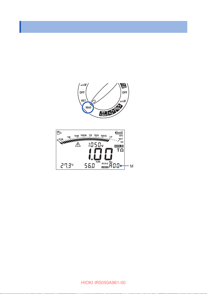
Checking Recorded Data
HIOKI IR5050A961-00
6.2 Checking Recorded Data
• The content of a manual record is viewed on the LCD of the instrument.
• For logging records, only the last value is viewed on the LCD of the instrument. The
entire record is viewed on a PC using Sequence Maker.
See: “5.6 Communicating with PC” (p. 79)
Turn the rotary switch to READ.
1
The recorded data appears.
Press the key and key to choose the memory number you wish to
2
view.
The data stored under the number appears.
Use the key and key to switch to the next data.
PI and DAR measurement: t
SV measurement: Data of every step
DD measurement: Data upon completion of the measurement and
Hold down the MEM key for more than one second to check the recording date
and time.
Press any key to return to the original display.
90
Memory No.
data and t2 data
1
data one minute after completion
Page 91
Checking Recorded Data
HIOKI IR5050A961-00
The recording method of the displayed record is identied as follows.
Memory number is [Lr] Logging recording data
Memory number is not [Lr] Manual recording data
The type of manual record is identied as follows.
[PI] is lit PI (polarization index) data
[DAR] is lit DAR (dielectric absorption ratio) data
[SV] is lit SV (step voltage test) data
[Ramp] is lit Ramp (ramp voltage test) data
[DD] is lit DD (dielectric discharge) data
• For logging records, only the last data is displayed.
• For data that is not displayed on the LCD, you can display this data with the same
key operations as for switching the display method during a test.
91
Page 92
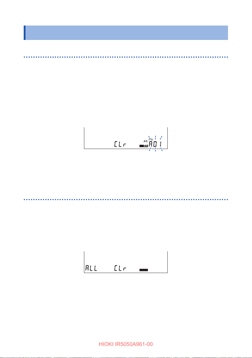
Deleting Recorded Data
Year
TIMER
PI DAR S V
Ramp
DD
Month Day
HID
Year
TIMER
PI DAR S V
Ramp
DD
Month Day
HID
HIOKI IR5050A961-00
6.3 Deleting Recorded Data
Deleting data with the selected number
Select the data to be deleted, and delete only this selection.
Turn the rotary switch to READ.
1
The recorded data appears.
Press the key and key to choose the memory number of the data to
2
delete.
Press the CLR key.
3
[CLr] appears and the memory number blinks.
FILTER
NOISE
hr:min:sec
Press the ENTER key.
4
[CLr] blinks and the data is deleted.
TCPIDARSVDD
COMP
MEMORY
READ
LOGGING
USED
No.
Deleting all data
Delete all the manual records and logging records simultaneously.
Turn the rotary switch to READ.
1
The recorded data appears.
Press the CLR key twice.
2
[ALL CLr] appears.
Press the ENTER key.
3
[ALL CLr] blinks and all data is deleted.
92
FILTER
NOISE
hr:min:sec
TCPIDARSVDD
COMP
MEMORY
READ
LOGGING
USED
No.
Page 93
7
HIOKI IR5050A961-00
Specications
7.1 General Specications
Operating
environment
Operating
temperature and
humidity range
Storage temperature
and humidity range
Dust resistance and
water resistance
Standards Safety: EN 61010
Power supply Use one of the following.
Continuous
operating time
Backup battery life Approx. 10 years (Reference value at 23
Dimensions Approx. 195W
Indoor use, pollution degree 2, altitude up to 2000 m (6562 ft.)
−20
C to 40°C (−4°F to 104°F), 80% RH or less (non-condensing)
°
40°C to 45°C (104°F to 113°F), 80% RH or less (non-condensing)
45°C to 50°C (113°F to 122°F), 80% RH or less (non-condensing)
−25
C to 65°C (−13°F to 149°F), 80% RH or less (non-condensing)
°
IP40 (when the protector is attached; excluding terminals section)
IP65 (C0212 Carrying Case) (EN 60529)
The protection rating for the enclosure of this instrument (based on
EN 60529) is IP40 or IP65.
IP40, IP65:
This indicates the degree of protection provided by the enclosure
of the device for use in hazardous locations, entry of solid foreign
objects, and the ingress of water.
IP4X: Protected against access to hazardous parts with wire
measuring 1.0 mm in diameter. The equipment inside the
enclosure is protected against entry by solid foreign objects
larger than 1.0 mm in diameter.
IPX0: The equipment inside the enclosure is not protected against the
harmful eects of water.
IP6X: Protected against access to hazardous parts with wire
measuring 1.0 mm in diameter. Dustproof type (Dust shall not
penetrate the enclosure.)
IPX5: The equipment inside the enclosure is protected against the
harmful eects of water projected in jets against the enclosure
from any direction.
EMC: EN 61326
Insulation tester: IEC 61557-1, IEC 61557-2
• LR6 Alkaline battery
Rated supply voltage: 1.5 V DC ×8
• HR6 Nickel-metal hydride battery ×8
Rated supply voltage: 1.2 V DC ×8
Maximum rated power: 12 VA
Eective range of battery: 8.8 V ±0.2 V to 13.6 V
Using LR6 Alkaline battery
Approx. 5 hours (Generating 5 kV, open between + & − terminals,
Approx. 4 hours (Generating 5 kV, open between + & − terminals,
×
8
×
8 (Reference value at 23°C)
×
backlight o, comparator o, and Z3210 not installed)
backlight o, comparator o, Z3210 installed, and
using wireless communications)
254H × 89D mm (Approx. 7.7"W × 10.0"H × 3.5"D)
C)
°
93
Page 94

General Specications
HIOKI IR5050A961-00
Weight Approx. 1.7 kg (Approx. 60.0 oz.) (Including battery and excluding
other accessories)
Product warranty
duration
Included
accessories
Options See: “Options (Sold Separately)” (p. 9)
3 years
See: “Checking Package Contents” (p. 8)
94
Page 95
Input Specications, Output Specications, and Measurement Specications
HIOKI IR5050A961-00
7.2 Input Specications, Output Specications,
and Measurement Specications
Basic specications and accuracy specications
Measurement item Insulation resistance measurement: DC voltage application, voltage
and current detection
PV insulation resistance measurement: DC voltage application,
voltage and current detection
Leakage current measurement
Voltage measurement: Mean-value rectication RMS value indication
Capacitance measurement (DD function): Discharge method
Input/output
terminals
Maximum rated
voltage between
terminals
Maximum rated lineto-ground voltage
Rated operating
conditions
Accuracy guarantee
conditions
+ terminal: Connect the red test lead to this terminal
Insulation resistance measurement: Voltage output terminal (+)
PV insulation resistance measurement: Voltage output terminal (+)
Voltage measurement: + terminal
− terminal: Connect the black test lead to this terminal
Insulation resistance measurement: Terminal into which the current
from the object under measurement ows (−)
PV insulation resistance measurement: Terminal into which the
current from the object under measurement ows (−)
Voltage measurement: − terminal
GUARD terminal: Connect the blue test lead to this terminal.
This terminal is used only during insulation
resistance and PV insulation resistance
measurements.
1000 V AC/2000 V DC (voltage measurement, between + &
− terminals)
1000 V (Measurement category IV), Anticipated transient overvoltage
12,000 V
2000 V (Measurement category III), Anticipated transient overvoltage
15,000 V
Operating temperature and humidity range:
See “Operating temperature and humidity range” (p. 93).
Orientation: Horizontal
Power supply voltage: Eective range of battery
External magnetic eld: 400 A/m or less (DC and 50 Hz/60 Hz)
Accuracy guarantee duration: 1 year
Accuracy guarantee temperature and humidity range: 23
than 80% RH
±90°
°C ±5°
C, less
95
Page 96
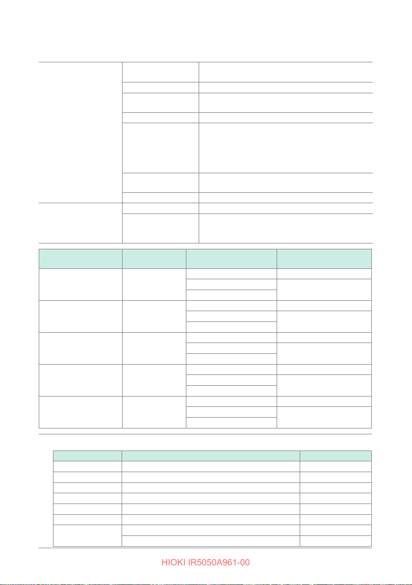
Input Specications, Output Specications, and Measurement Specications
HIOKI IR5050A961-00
(1) Insulation resistance measurement
Output voltage Output voltage
range
Preset test voltage 250 V, 500 V, 1 kV, 2.5 kV, 5 kV
Setting resolution 250 V to 1 kV: 10 V steps
Open circuit voltage −0% and +10% of setting
Lower limit of
resistance that
can maintain rated
measurement
voltage
Rated current
Short-circuit current 2 mA or less
Output voltage
monitor
Rated measurement
voltage (setting)
250 V 500 G
500 V 1.00 T
1000 V 2.00 T
2500 V 5.00 T
5000 V 10.0 T
Range conguration (auto range)
Range Display range Resolution
10 M
Ω
100 M
Ω
1000 M
10 G
Ω
100 G
Ω
1000 G
10 T
Ω
Display range 0 V to 5800 V
Accuracy
Maximum
displayed value
Ω
Ω
Ω
Ω
Ω
Ω
Ω
250 V DC to 5.2 kV DC
1 kV to 5.2 kV: 25 V steps
Rated measurement voltage (setting) ÷ rated
current
1 mA to 1.2 mA (Electric current that can be
generated with the set test voltage is maintained)
5% rdg ±5 dgt
±
Add 5 dgt to the accuracy for the voltage of
30 V or less
Accuracy guarantee
range
0.00 MΩ to 2.50 G
2.51 G
251 G
0.00 MΩ to 5.00 G
5.01 G
501 G
0.00 MΩ to 9.99 M
9.0 MΩ to 99.9 M
90 MΩ to 999 M
0.90 GΩ to 9.99 G
9.0 GΩ to 99.9 G
90 GΩ to 999 G
0.90 TΩ to 9.99 T
9.0 TΩ to 10.0 T
to 250 G
Ω
to 500 G
Ω
to 500 G
Ω
to 1.00 T
Ω
0.00 MΩ to 10.0 G
10.1 G
501 G
0.00 MΩ to 25.0 G
25.1 G
501 G
0.00 MΩ to 50.0 G
50.1 G
501 G
to 500 G
Ω
to 2.00 T
Ω
to 500 G
Ω
to 5.00 T
Ω
to 500 G
Ω
to 10.0 T
Ω
Ω ±
Ω
Ω
Ω ±
Ω
Ω
Ω
Ω
Ω
Ω
Ω
Ω
Ω
Ω
Accuracy (inherent
uncertainty A)
Ω ±
Ω
Ω
Ω ±
Ω
Ω
Ω ±
Ω
Ω
5% rdg ±5 dgt
5% rdg ±5 dgt
5% rdg ±5 dgt
5% rdg ±5 dgt
5% rdg ±5 dgt
20% rdg
±
20% rdg
±
20% rdg
±
20% rdg
±
20% rdg
±
0.01 M
0.1 M
1 M
0.01 G
0.1 G
1 G
0.01 T
0.1 T
Ω
Ω
Ω
Ω
Ω
Ω
Ω
Ω
96
Page 97
Input Specications, Output Specications, and Measurement Specications
HIOKI IR5050A961-00
Operation
uncertainty (B)*
1
Guaranteed range
of operation
uncertainty
Eect of supplied
voltage (E2) *
Eect of temperature
1
(E3) *
1
30% rdg
±
Greater than or equal to 0.1 M
but less than or equal to the
Ω
resistance value calculated by dividing the test voltage (setting) by
100 nA
Accuracy × 0.5 and within accuracy specications
Accuracy × 1.0 is added to the accuracy (applicable in the ambient
temperature range excluding 18°C to 28°C)
When the L9850-11 and L9850-12 test leads (10 m) are used, the
accuracy of 501 GΩ or more is not guaranteed.
Eect of capacitance
Within
10% at a capacitance of 5 µF or less (including drift)
±
component
Number of possible
200 or more
measurements
Overload protection 1100 V AC (for 10 sec. between + & − terminals)
6000 V DC (for 10 sec. between + & − terminals)
Display update Once/sec. or more (when the lter is on, 0.25 times/sec.)
Response time Measurement condition: Resistive load
(output voltage 5000 V, resistive load 1 T
Filter o: Within 3 sec.
Filter on: Within 10 sec.
Induction noise
3 mA max
removal
*1. B, E2, and E3 are the symbols specied by IEC61557.
)
Ω
97
Page 98
Input Specications, Output Specications, and Measurement Specications
HIOKI IR5050A961-00
(2) Current (leakage current) measurement
Electric current is measured with the test voltage generated, as in insulation
resistance measurement.
Accuracy guarantee
range
Accuracy
Range conguration (auto range)
Range Display range Resolution
10 nA 0.00 nA to 9.99 nA 0.01 nA
100 nA 9.0 nA to 99.9 nA 0.1 nA
1000 nA 90 nA to 999 nA 1 nA
10 µA 0.90 µA to 9.99 µA 0.01 µA
100 µA 9.0 µA to 99.9 µA 0.1 µA
1 mA
Eect of temperature Accuracy
Response time Measurement condition: Resistive load
1.00 nA to 3.00 mA
5% rdg ±1 nA
±
90 µA to 999 µA 1 µA
0.90 mA to 3.00 mA 0.01 mA
1.0 is added to the accuracy (applicable in the ambient
temperature range excluding 18°C to 28°C)
When the L9850-11 and L9850-12 test leads (10 m) are used, the
accuracy is not guaranteed if the current is below the value obtained
by dividing the test voltage (set value) by 500 GΩ.
Filter o: Within 3 sec.
Filter on: Within 10 sec.
×
(output voltage 5000 V, resistive load 1 T
(3) Voltage measurement
Accuracy guarantee
range
Accuracy
Range conguration
30 V AC to 1000 V AC (45 Hz to 65 Hz)
10 V DC to ±2000 V DC
±
3% rdg ±3 dgt
±
Add ±5 dgt to the accuracy for the voltage between −30 V and 30 V.
)
Ω
Range Display range Resolution
AC 1000 V 30 V to 1000 V 1 V
DC 2000 V
DC/AC automatic
judgment range
Input resistance 500 k
Eect of temperature Accuracy
Overload protection 1100 V AC (for 1 min. between + & − terminals)
Display update Once/sec. or more
98
5 V to ±2000 V
Zero-display range: 4 count or less
Judged as AC at 30 V or more (50 Hz/60 Hz).
A ow on which a large AC component of 30 V or more is
superimposed is judged as AC.
or more (DC, 45 Hz to 65 Hz)
Ω
excluding 18°C to 28°C)
2200 V DC (for 1 min. between + & − terminals)
±
0.1 per 1°C (applicable in the ambient temperature range
×
1 V
Page 99
Input Specications, Output Specications, and Measurement Specications
HIOKI IR5050A961-00
(4) Capacitance measurement
Accuracy guarantee
range
Accuracy
Range conguration (auto range)
Range Display range Resolution
100 nF 0.0 nF to 99.9 nF 0.1 nF
1000 nF 100 nF to 999 nF 1 nF
10 μF
Eect of temperature Accuracy
• The capacitance measurement is automatically taken after the insulation resistance
measurement ends.
• The capacitance measurement is not performed if the output voltage is 250 V or less during
the insulation resistance measurement. The instrument will display [---] as the capacitance if it
is unable to perform capacitance measurement.
10.0 nF to 25.0 μF
10% rdg ±5 nF
±
1.00 μF to 9.99 μF
10.0 μF to 25.0 μF
1.0 is added to the accuracy (applicable in the ambient
temperature range excluding 18°C to 28°C)
×
0.01 μF
0.1 μF
(5) PV insulation resistance measurement
Output voltage Output voltage range 250 V DC to 2.00 kV DC
Preset test voltage 500 V, 1 kV, 1.5 kV
Setting resolution 250 V to 1 kV: 10 V steps
Open circuit voltage*
Lower limit of
resistance that
can maintain rated
measurement voltage
Rated current Rated measurement voltage (setting) ÷ rated
Short-circuit current 2 mA or less
Output voltage
monitor
*1. PV insulation resistance has approx. 660 k
terminal, so the output voltage is divided by 660 kΩ and the resistance connected between
the measurement terminals.
Example: When open-circuit voltage is measured with a DMM with an input impedance of
10 MΩ, the voltage is divided by 660 kΩ and 10 MΩ.
Display range 0 V to 5800 V
Accuracy
1 kV to 2 kV: 25 V steps
1
−0% and +10% of setting
20 M
Ω
measurement voltage that can maintain open
circuit voltage
5% rdg ±5 dgt
±
Add 5 dgt to the accuracy for the voltage of
30 V or less
of current-limiting resistance on the +
Ω
Rated measurement
voltage (setting)
500 V 100 G
1000 V 100 G
Maximum
displayed value
Ω
Ω
Accuracy guarantee
range
0.00 MΩ to 5.00 G
5.01 G
0.00 MΩ to 10.0 G
10.1 G
to 100 G
Ω
to 100 G
Ω
Ω ±
Ω ±
Ω ±
Ω ±
Accuracy (inherent
uncertainty A)
5% rdg ±5 dgt
20% rdg
5% rdg ±5 dgt
20% rdg
99
Page 100
Input Specications, Output Specications, and Measurement Specications
HIOKI IR5050A961-00
1500 V 100 G
Range conguration (auto range)
Range Display range Resolution
10 M
Ω
100 M
Ω
1000 M
Ω
10 G
Ω
100 G
Ω
Eect of supplied
voltage
Eect of temperature Accuracy
Eect of capacitance
component
Number of possible
measurements
Overload protection 1100 V AC (for 10 sec. between + & − terminals)
Display update Once/sec. or more
Response time Measurement condition: Resistive load
Accuracy
temperature range excluding 18°C to 28°C)
Within
1000 or more
6000 V DC (for 10 sec. between + & − terminals)
Within 4 sec.
Ω
0.5 and within accuracy specications
×
1.0 is added to the accuracy (applicable in the ambient
×
10% rdg at a capacitance of 5 µF or less (including drift)
±
0.00 MΩ to 20.0 G
20.1 G
0.00 MΩ to 9.99 M
9.0 MΩ to 99.9 M
90 MΩ to 999 M
0.90 GΩ to 9.99 G
9.0 GΩ to 99.9 G
90 GΩ to 100 G
to 100 G
Ω
(output voltage 1500 V, resistive load 80 G
Ω ±
Ω ±
Ω
Ω
Ω
Ω
Ω
Ω
5% rdg ±5 dgt
20% rdg
0.01 M
Ω
0.1 M
Ω
1 M
Ω
0.01 G
Ω
0.1 G
Ω
1 G
Ω
)
Ω
100
 Loading...